Embed Size (px)
Citation preview
429
WOOD RESEARCH 60 (3): 2015 429-440
INFLUENCE OF PNEUMATIC PRESSURE ON
DELAMINATION FACTOR OF DRILLING MEDIUM
DENSITY FIBERBOARD
Wang Kun, Shen Qi, Wang ChengTongji University, College of Mechanical Engineering
Shanghai, China
Liu ChunjieChangzhou Institute of Technology , School of Mechanical and Electronic
EngineeringChangzhou, China
(Received February 2014)
ABSTRACT
Drilling quality of medium density fiberboards (MDF) is significantly affected by delamination in furniture industry. The feed generated by a multi-spindle drilling machine tool is the so-called pneumatic pressure which provides a complex non-linear feed. The present study focuses on the machining parameters on delamination factor at entry and exit of the holes in drilling of MDF. The objective was to establish the mathematical model of feed based on theoretical analysis and to establish the second order polynomial model using response surface methodology between cutting parameters and delamination around the MDF through-holes. The analysis of variance (ANOVA) was employed to verify the validity of the mathematical models. It is found that at low value of feed pressure, the delamination factor increases with the increase of feed pressure. However at high level, the delaminaiton factor remains insensitive with the change of pressure, and the hardness has the similar trend on delamination but has an opposite effect.
KEYWORDS: Medium density fiberboard (MDF), pneumatic pressure, delamination factor, analysis of variance (ANOVA).
INTRODUCTION
As an important kind of artificial board product, medium-density fiberboard (MDF) is widely used in furniture industry, exterior and interior construction application due to its excellent
430
WOOD RESEARCH
characteristics. When competed to solid wood, it has more attractive and favorable properties such as high strength, good surface characteristics, dimensional stability, stable performance and excellent machinability and hence found many applications in wood industries (Davim et al. 2008, Lin and Bhattacharyya 2006). The board is usually coated with a layer of wood veneer or plastic laminate to get the appearance of natural wood products (Davim and Silva 2007).
Drilling is one of the most frequently used machining process and is often considered a final process used in assembly of wood products. When drilling, the chisel edge of the twist drill cannot cut through the board, it would lead to a frustrated result, delamination (Zhao and Ehmann 2002). Delamination occurred in drilling is the main concern and reduces the strength against fatigue, resulting in a poor assembly tolerance. What’s more, the delamination degrades the performance and reduces the aesthetical aspect of the final product.
From literature, it has been asserted that the machining of MDF is strongly dependent on the machining parameters. Davim et al. (2008) presented a study on the damage observed at the entrance of the blind holes of drilling MDF panels. Using cemented carbide special drills to reveal the relationship between damage feature and the machining parameters such as feed rate and spindle speed. The results of the investigation showed that the delamination factor increases with the increase of feed rate and decreases with the increase of spindle speed. At the same time, due to different layers, namely wood coated and melamine coated, the value of delamination is quite different.
When Gaitonde et al. (2008a) has to optimize the machining parameters of drilling of MDF panels, they employed Taguchi’s L9 orthogonal array to complete the experiment (Gaitonde et al. 2008a). Response surface methodology was considered for estimating the effect of different machining parameters on delamination. The reporter strongly recommend high spindle speed low feed rate in order to get small delamination factor.
The investigation presented by Palanikumar et al. (2009) focused on the effects of machining parameters on entry and exit side of medium density fiber boards using carbide twist drills. The orthogonal array, signal-to-noise (S/N) ratio and analysis of variance (ANOVA) are employed. The influence of process variables like spindle speed, feed rate, and drill diameter are elaborately investigated as well as their interactions. The author came to a conclusion like the above.
It is noticed that most researchers did experiments on the on CNC machining center which can provide a constant uniform feed rate. But as the 32 mm furniture system most professional machine tool- multi-spindle drilling machine is seldom mentioned. The feed of this machine tool is provided by pressure generated by air compressor. It is the so-called feed pressure. Due to the compressibility the air, the feed rate is a complex variable. Literature survey reveals that no systematic study has been reported to analyze the main and interaction effects of drilling process by a multi-spindle drilling machine on delamination factors.
The present investigation is aimed at determining the effects of process parameters on delamination factor at entry and exit of the holes in drilling of MDF material using multi-spindle drilling machine. Three different types of twist drills were tested. When did the experiment, design of experiment (DOE) was employed to design a reasonable experiment to get the results. The influence of process variables like feed pressure (P), drill diameter (D), drill hardness (H) are investigated simultaneously to study their effects on delamination factor (Fd) at entry and exit of the holes using second order polynomial response surface model (Hunter 2006, Onwubolu 2006).
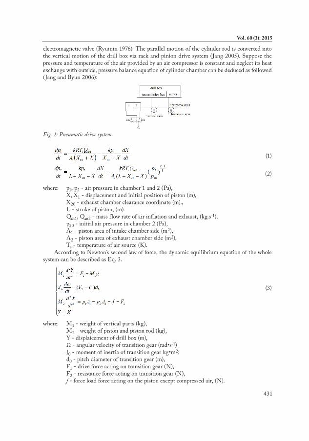
ModelsPneumatic drive system of multi-spindle drilling machine discussed in this paper is shown in
Fig. 1. As shown in the figure, the on-off of the cylinder is controlled by a two-position five-way
431
Vol. 60 (3): 2015
electromagnetic valve (Ryumin 1976). The parallel motion of the cylinder rod is converted into the vertical motion of the drill box via rack and pinion drive system (Jang 2005). Suppose the pressure and temperature of the air provided by an air compressor is constant and neglect its heat exchange with outside, pressure balance equation of cylinder chamber can be deduced as followed (Jang and Byun 2006):
Fig. 1: Pneumatic drive system.
(1)
(2)
where: p1, p2 - air pressure in chamber 1 and 2 (Pa), X, X1 - displacement and initial position of piston (m), X20 - exhaust chamber clearance coordinate (m)., L - stroke of piston, (m). Qm1, Qm2 - mass f low rate of air inflation and exhaust, (kg.s-1), p20 - initial air pressure in chamber 2 (Pa), A1 - piston area of intake chamber side (m2), A2 - piston area of exhaust chamber side (m2), Ts - temperature of air source (K).According to Newton’s second law of force, the dynamic equilibrium equation of the whole
system can be described as Eq. 3.
(3)
where: M1 - weight of vertical parts (kg), M2 - weight of piston and piston rod (kg), Y - displaicement of drill box (m), Ω-angularvelocityoftransitiongear(rad•s-1) J0-momentofinertiaoftransitiongearkg•m2; d0 - pitch diameter of transition gear (m), F1 - drive force acting on transition gear (N), F2 - resistance force acting on transition gear (N), f - force load force acting on the piston except compressed air, (N).
432
WOOD RESEARCH
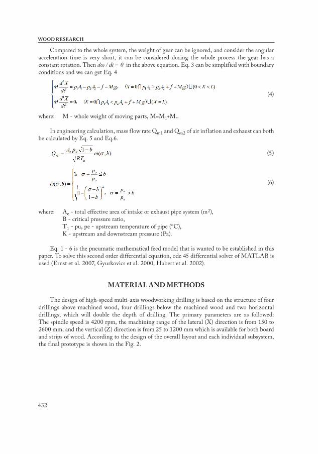
Compared to the whole system, the weight of gear can be ignored, and consider the angular acceleration time is very short, it can be considered during the whole process the gear has a constant rotation. Then dω / dt = 0 in the above equation. Eq. 3 can be simplified with boundary conditions and we can get Eq. 4
(4)
where: M - whole weight of moving parts, M=M1+M..
In engineering calculation, mass f low rate Qm1 and Qm2 of air inflation and exhaust can both be calculated by Eq. 5 and Eq.6.
(5)
(6)
where: Ae - total effective area of intake or exhaust pipe system (m2), B - critical pressure ratio, T1 - pu, pe - upstream temperature of pipe (°C), K - upstream and downstream pressure (Pa).
Eq. 1 - 6 is the pneumatic mathematical feed model that is wanted to be established in this paper. To solve this second order differential equation, ode 45 differential solver of MATLAB is used (Ernst et al. 2007, Gyurkovics et al. 2000, Hubert et al. 2002).
MATERIAL AND METHODS
The design of high-speed multi-axis woodworking drilling is based on the structure of four drillings above machined wood, four drillings below the machined wood and two horizontal drillings, which will double the depth of drilling. The primary parameters are as followed: The spindle speed is 4200 rpm, the machining range of the lateral (X) direction is from 150 to 2600 mm, and the vertical (Z) direction is from 25 to 1200 mm which is available for both board and strips of wood. According to the design of the overall layout and each individual subsystem, the final prototype is shown in the Fig. 2.
433
Vol. 60 (3): 2015
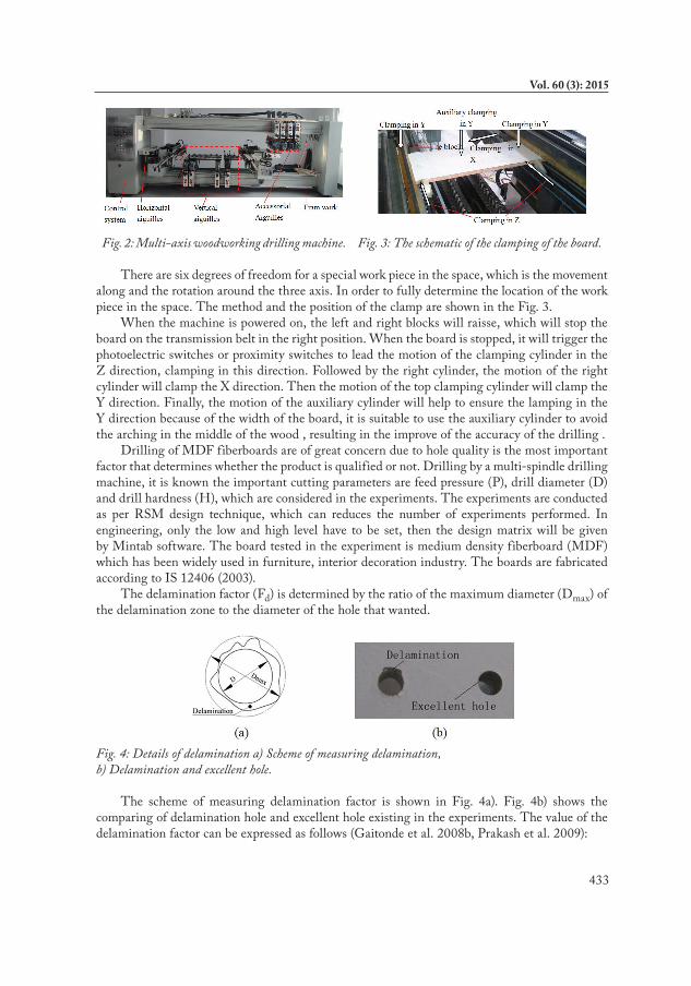
Fig. 2: Multi-axis woodworking drilling machine. Fig. 3: The schematic of the clamping of the board.
There are six degrees of freedom for a special work piece in the space, which is the movement along and the rotation around the three axis. In order to fully determine the location of the work piece in the space. The method and the position of the clamp are shown in the Fig. 3.
When the machine is powered on, the left and right blocks will raisse, which will stop the board on the transmission belt in the right position. When the board is stopped, it will trigger the photoelectric switches or proximity switches to lead the motion of the clamping cylinder in the Z direction, clamping in this direction. Followed by the right cylinder, the motion of the right cylinder will clamp the X direction. Then the motion of the top clamping cylinder will clamp the Y direction. Finally, the motion of the auxiliary cylinder will help to ensure the lamping in the Y direction because of the width of the board, it is suitable to use the auxiliary cylinder to avoid the arching in the middle of the wood , resulting in the improve of the accuracy of the drilling .
Drilling of MDF fiberboards are of great concern due to hole quality is the most important factor that determines whether the product is qualified or not. Drilling by a multi-spindle drilling machine, it is known the important cutting parameters are feed pressure (P), drill diameter (D) and drill hardness (H), which are considered in the experiments. The experiments are conducted as per RSM design technique, which can reduces the number of experiments performed. In engineering, only the low and high level have to be set, then the design matrix will be given by Mintab software. The board tested in the experiment is medium density fiberboard (MDF) which has been widely used in furniture, interior decoration industry. The boards are fabricated according to IS 12406 (2003).
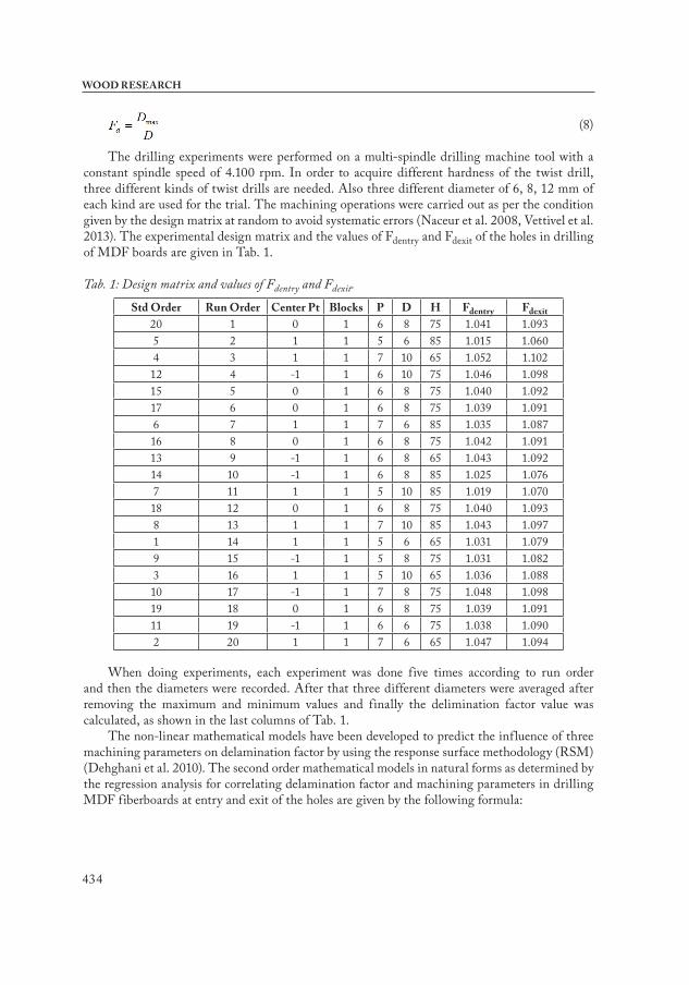
The delamination factor (Fd) is determined by the ratio of the maximum diameter (Dmax) of the delamination zone to the diameter of the hole that wanted.
Fig. 4: Details of delamination a) Scheme of measuring delamination, b) Delamination and excellent hole.
The scheme of measuring delamination factor is shown in Fig. 4a). Fig. 4b) shows the comparing of delamination hole and excellent hole existing in the experiments. The value of the delamination factor can be expressed as follows (Gaitonde et al. 2008b, Prakash et al. 2009):
434
WOOD RESEARCH
(8)
The drilling experiments were performed on a multi-spindle drilling machine tool with a constant spindle speed of 4.100 rpm. In order to acquire different hardness of the twist drill, three different kinds of twist drills are needed. Also three different diameter of 6, 8, 12 mm of each kind are used for the trial. The machining operations were carried out as per the condition given by the design matrix at random to avoid systematic errors (Naceur et al. 2008, Vettivel et al. 2013). The experimental design matrix and the values of Fdentry and Fdexit of the holes in drilling of MDF boards are given in Tab. 1.
Tab. 1: Design matrix and values of Fdentry and Fdexit.
Std Order Run Order Center Pt Blocks P D H Fdentry Fdexit20 1 0 1 6 8 75 1.041 1.0935 2 1 1 5 6 85 1.015 1.0604 3 1 1 7 10 65 1.052 1.102
12 4 -1 1 6 10 75 1.046 1.09815 5 0 1 6 8 75 1.040 1.09217 6 0 1 6 8 75 1.039 1.0916 7 1 1 7 6 85 1.035 1.08716 8 0 1 6 8 75 1.042 1.09113 9 -1 1 6 8 65 1.043 1.09214 10 -1 1 6 8 85 1.025 1.0767 11 1 1 5 10 85 1.019 1.07018 12 0 1 6 8 75 1.040 1.0938 13 1 1 7 10 85 1.043 1.0971 14 1 1 5 6 65 1.031 1.0799 15 -1 1 5 8 75 1.031 1.0823 16 1 1 5 10 65 1.036 1.08810 17 -1 1 7 8 75 1.048 1.09819 18 0 1 6 8 75 1.039 1.09111 19 -1 1 6 6 75 1.038 1.0902 20 1 1 7 6 65 1.047 1.094
When doing experiments, each experiment was done five times according to run order and then the diameters were recorded. After that three different diameters were averaged after removing the maximum and minimum values and finally the delimination factor value was calculated, as shown in the last columns of Tab. 1.
The non-linear mathematical models have been developed to predict the influence of three machining parameters on delamination factor by using the response surface methodology (RSM) (Dehghani et al. 2010). The second order mathematical models in natural forms as determined by the regression analysis for correlating delamination factor and machining parameters in drilling MDF fiberboards at entry and exit of the holes are given by the following formula:
435
Vol. 60 (3): 2015
(9)
(10)
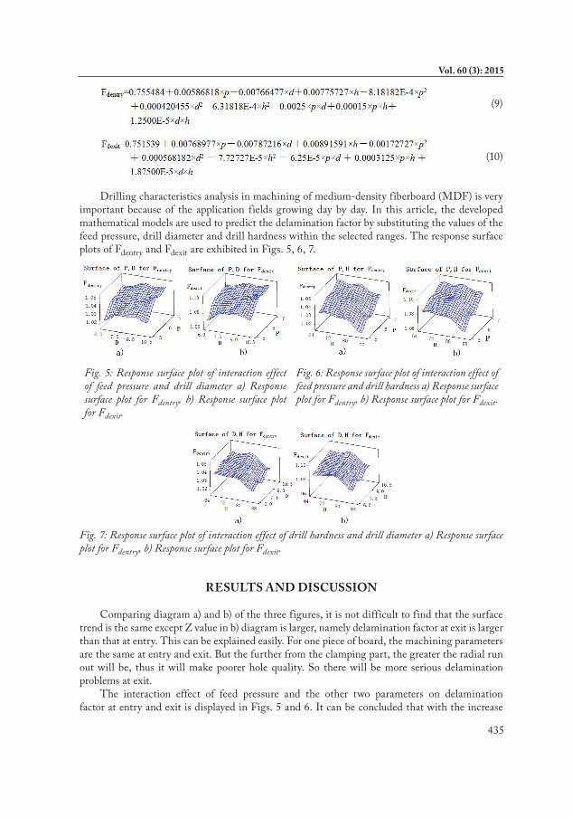
Drilling characteristics analysis in machining of medium-density fiberboard (MDF) is very important because of the application fields growing day by day. In this article, the developed mathematical models are used to predict the delamination factor by substituting the values of the feed pressure, drill diameter and drill hardness within the selected ranges. The response surface plots of Fdentry and Fdexit are exhibited in Figs. 5, 6, 7.
Fig. 5: Response surface plot of interaction effect of feed pressure and drill diameter a) Response surface plot for Fdentry, b) Response surface plot for Fdexit.
Fig. 6: Response surface plot of interaction effect of feed pressure and drill hardness a) Response surface plot for Fdentry, b) Response surface plot for Fdexit.
Fig. 7: Response surface plot of interaction effect of drill hardness and drill diameter a) Response surface plot for Fdentry, b) Response surface plot for Fdexit.
RESULTS AND DISCUSSION
Comparing diagram a) and b) of the three figures, it is not difficult to find that the surface trend is the same except Z value in b) diagram is larger, namely delamination factor at exit is larger than that at entry. This can be explained easily. For one piece of board, the machining parameters are the same at entry and exit. But the further from the clamping part, the greater the radial run out will be, thus it will make poorer hole quality. So there will be more serious delamination problems at exit.
The interaction effect of feed pressure and the other two parameters on delamination factor at entry and exit is displayed in Figs. 5 and 6. It can be concluded that with the increase
436
WOOD RESEARCH
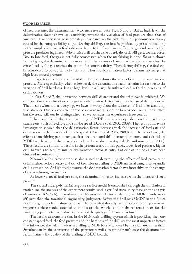
of feed pressure, the delamination factor increases in both Figs. 5 and 6. But at high level, the delamination factor shows less sensitivity towards the variation of feed pressure than that of low level. The critical value is probably 6 bar based on the pictures. This phenomenon mainly caused by the compressibility of gas. During drilling, the feed is provided by pressure resulting in the complex non-linear feed rate as is elaborated in front chapter. But the general trend is high pressure produces high feed. When twist drill touched the board, the drill will get a counter force. Due to low feed, the gas is not fully compressed when the machining is done. So as is shown in the figure, the delamination increases with the increase of feed pressure. Once it reaches the critical value, the gas reaches the point of incompressibility. Then during drilling, the feed can be considered to be substantially constant. Thus the delamination factor remains unchanged at high level of feed pressure.
In Figs. 6 and 7, it can be found drill hardness shows the same effect but opposite to feed pressure. More specifically, when at low level, the delamination factor remains insensitive to the variation of drill hardness, but at high level, it will significantly reduced with the increasing of drill hardness.
In Figs. 5 and 7, the interaction between drill diameter and the other two is exhibited. We can find there are almost no changes in delamination factor with the change of drill diameter. That means when it is not very big, we have no worry about the diameter of drill holes according to customers. Due to experiment error or measurement error, the bumps occurred at the surface, but the trend still can be distinguished. So we consider the experiment is successful.
It has been found that the machining of MDF is strongly dependent on the machining parameters, such as feed rate and spindle speed (Davim et al. 2007, 2008). The results of Davim’s investigation showed that the delamination factor increases with the increase of feed rate and decreases with the increase of spindle speed. (Davim et al. 2007, 2008). On the other hand, the effects of machining parameters, such as feed rate and drill diameter, on entry and exit side of MDF boards using carbide twist drills have been also investigated (Palanikumar et al. 2009). Those results are similar to results in the present work. In this paper, lower feed pressure, higher drill hardness to acquire smaller delamination factor at entry and exit of the holes have been obtained experimentally.
Meanwhile the present work is also aimed at determining the effects of feed pressure on delamination factor at entry and exit of the holes in drilling of MDF material using multi-spindle drilling machine. At high feed pressure, the delamination factor shows insensitive to the change of the machining parameters.
At lower values of feed pressure, the delamination factor increases with the increase of feed pressure.
The second order polynomial response surface model is established through the simulation of matlab and the analysis of the experiment results, and is verified its validity through the analysis of variance (ANOVA), to evaluate the delamination factor in drilling of MDF boards more efficient than the traditional engineering judgment. Before the drilling of MDF in the future machining, the delamination factor will be estimated directly by the second order polynomial response surface model established in this article, which is the main reference index for the machining parameters adjustment to control the quality of the manufacture.
The results demonstrate that in the Multi-axis drilling system which is providing the non-constant speed feed, the feed pressure and the hardness of the drill are the most important factors that influences the delamination in drilling of MDF boards followed by the diameter of the drill. Simultaneously, the interaction of the parameters will also strongly influence the delamination factor, namely the quality of the drilling of MDF boards.
437
Vol. 60 (3): 2015
As the main indicator of the quality of hole machining, the delamination factor shows that the better effect of processing when it is closer to 1.
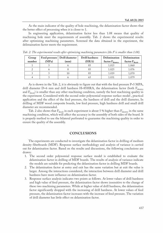
In engineering application, delamination factor less than 1.08 means that quality of machining hole meet the requirements of assembly. Tab. 2 shows the experimental results after optimizing machining parameters. Screened the data obtained in the experiment, the delimaination factor meets the requirement.
Tab. 2: The experimental results after optimizing machining parameters (the F is smaller than 1.08).
Group number
Feed pressure (MPa)
Drill diameter (mm)
Drill hardness (HRA)
Delimination factor Fdentry
Delimination factor Fdexit
1 5 6 85 1.015 1.0602 6 8 85 1.025 1.0763 5 10 85 1.019 1,0704 5 6 65 1.031 1.079
As is shown in the Tab. 2, it is obviously to figure out that with the feed pressure P=5 MPA, drill diameter D=6 mm and drill hardness H=85HRA, the delamination factor (both Fdentry and Fdexit) is smaller than any other machining condition, namely the best machining quality in the experiment. Considered with the second order polynomial response surface model , practical application and the effect of the feed pressure, the hardness of drill and the drill diameter, In drilling of MDF wood composite boards, low feed pressure, high hardness drill and small drill diameter are recommended.
Tab. 2 also shows that Fdexit in each experiment is about 5 % higher than Fdentry in the same machining condition, which will affect the accuracy in the assembly of both sides of the board. It is properly method to use the bilateral perforated to guarantee the machining quality in order to ensure the quality of the assembly.
CONCLUSIONS
The experiments are conducted to investigate the delamination factor in drilling of medium density fiberboards (MDF). Response surface methodology and analysis of variance is carried out for delamination factor. Based on the results and discussions, the following conclusions are drawn:
1. The second order polynomial response surface model is established to evaluate the delamination factor in drilling of MDF boards. The results of analysis of variance indicate the models are suitable for predicting the delamination factor in drilling MDF boards.
2. The delamination factor at entry and exit has the same variation but at exit the value is larger. Among the interactions considered, the interaction between drill diameter and drill hardness have more influence on delamination factor.
3. Response surface analysis indicates two points as follows. At lower values of drill hardness and high value of feed pressure, the delamination factor shows insensitive to the change of these two machining parameters. While at higher value of drill hardness, the delamination factor significantly dropped with the increasing of drill hardness. At lower values of feed pressure, the delamination factor increases with the increase of feed pressure. The variation of drill diameter has little effect on delamination factor.
438
WOOD RESEARCH
ACKNOWLEDGMENTS
The work was financially supported by the Natural Science Foundation of China (51105279, 51275360, 51278381), the National Basic Research Program of China (973 Program: 2011CB013800), Huo Yingdong Foundation for Basic Research (121064), and the Fundamental Research Funds for the Central Universities.
REFERENCES
1. Davim, J.P., Gaitonde, V.N., Karnik, S.R., 2008: An investigative study of delamination in drilling of medium density fibreboard (MDF) using response surface models. International Journal of Advanced Manufacturing Technology 37(1-2): 49-57.
2. Davim, J.P., Clemente, V.C., Silva, S., 2008: Drilling investigation of MDF (medium density fibreboard). Journal of Materials Processing Technology 203(1-3): 537-541.
3. Davim, J.P., Clemente, V.C., Silva, S., 2007: Evaluation of delamination in drilling medium density fibreboard. Proceedings of the Institution of Mechanical Engineering. Part B-Journal of Engineering Manufacture 221(4): 655-658.
4. Dehghani, K., Nekahi, A., Mirzaie, M., 2010: Optimizing the bake hardening behavior of Al7075 using response surface methodology. Materials & Design 31(4): 1768-1775.
5. Ernst, D., Valavanis, K., R. Garcia, R., Craighead, J., 2007: Unmanned vehicle controller design, evaluation and implementation: From MATLAB to printed circuit board. Journal of Intelligent & Robotic Systems 49(1): 85-108.
6. Gaitonde, V.N., Karnik, S.R., Davim, J.P., 2008a: Prediction and minimization of delamination in drilling of medium-density fiberboard (MDF) using response surface methodology and Taguchi design. Materials and Manufacturing Processes 23(4): 377-384.
7. Gaitonde, V.N., Karnik, S.R., Davim, J.P., 2008b: Taguchi multiple-performance characteristics optimization in drilling of medium density fibreboard (MDF) to minimize delamination using utility concept. Journal of Materials Processing Technology 196(1): 73-78.
8. Gyurkovics, E., Coombes, K.R., Hunt, B.R., Lipsman, R.L., Osborn, J.E., Stuck, G.J., 2000: Differential equations with MATLAB. Periodica Mathematica Hungarica 40(1): 77-78.
9. Hunter, J.S., 2006: Response surface methodology - Current status and future directions - Discussion. Journal of Quality Technology 31: 41-47.
10. Hubert, L.J., Arabie, P., Meulman, J.J., 2002: Linear unidimensional scaling in the L 2. - Norm: Basic optimization methods using MATLAB. Journal of Classification 19(2): 303-328.
11. Jang, J., 2005: Simultaneous trajectory tracking control of position and force with pneumatic cylinder driving apparatus. Journal of Mechanical Science and Technology 19(5): 1107-1115.
12. Jang, J., Byun, J., 2006: A method of accurate position control with a pneumatic cylinder driving apparatus. Journal of Mechanical Science and Technology 20(7): 993-1001.
13. Lin, R., Houts, J., Bhattacharyya, D., 2006: Machinability investigation of medium-density fibreboard. Holzforschung 60(1): 71-77.
14. Naceur, H., Ben-Elechi, S., Batoz, J.L., Knopf-Lenoir, C., 2008: Response surface methodology for the rapid design of aluminum sheet metal forming parameters. Materials & Design 29(4): 781-790.
439
Vol. 60 (3): 2015
15. Onwubolu, G.C., 2006: Response surface methodology-based approach to CNC drilling operations. Journal of Materials Processing Technology 171(1): 41-47.
16. Palanikumar, K., Prakash, S.N., Manoharan, N., 2009: Experimental investigation and analysis on delamination in drilling of wood composite medium density fiber boards. Materials and Manufacturing Processes 24(12): 1341-1348.
17. Prakash, S., Palanikumar, K., Manoharan, N., 2009: Optimization of delamination factor in drilling medium-density fiberboards (MDF) using desirability-based approach. International Journal of Advanced Manufacturing Technology 45(3): 370-381.
18. Ryumin, S.V., 1976: Two-position pneumatic clamping fixture for honing compressor cylinder liners. Chemical and Petroleum Engineering 12: 744-745.
19. Vettivel, S.C., Selvakumar, N., Narayanasamy, R., Leema, N., 2013: Numerical modelling, prediction of Cu–W nano powder composite in dry sliding wear condition using response surface methodology. Materials & Design 50: 977-996.
20. Zhao, H.X., Ehmann, K.F., 2002: Development and performance analysis of new spade bit designs. International Journal of Machine Tools & Manufacture 42(13): 1403-1414.
Wang Kun*, Shen Qi, Wang ChengTongji University, Shanghai, College of Mechanical Engineering,
Shanghai 201804China
Corresponding author: [email protected],
Liu ChunjieChangzhou Institute of Technology
School of Mechanical and Electronic EngineeringChangzhou 213002
ChinaE-mail: [email protected]

440
WOOD RESEARCH