Embed Size (px)
Citation preview

Influence of bottom currents on the sedimentary processes at thewestern tip of the Gulf of Corinth, Greece
A. Beckers a,b,⁎, C. Beck b, A. Hubert-Ferrari a, E. Tripsanas c, C. Crouzet b, D. Sakellariou d,G. Papatheodorou e, M. De Batist fa Department of Geography, University of Liège, Liège B-4000, Belgiumb ISTerre, CNRS UMR 5275, University Savoie Mont Blanc, Le Bourget du Lac F-73376, Francec Shell U.K. Limited, Specialist Geology Team, Aberdeen AB12 3FY, UKd Institute of Oceanography, Hellenic Center for Marine Research, Anavyssos GR-19013, Greecee Laboratory of Marine Geology and Physical Oceanography, Department of Geology, University of Patras, Patras 26500, Greecef Renard Centre of Marine Geology, University of Gent, Gent B-9000, Belgium
a b s t r a c ta r t i c l e i n f o
Article history:Received 10 May 2015Received in revised form 31 January 2016Accepted 3 March 2016Available online 4 March 2016
We investigated the sedimentary processes that were active during the Holocene in the Gulf of Corinth, usinghigh-resolution seismic reflection profiles and gravity cores. Seismic reflection data clearly show the presenceof shallow-water sediment drifts at the western end of the Gulf, close to the Rion sill that links the Gulf to theIonian Sea. Short cores indicate that drifts are composed of homogenous bioturbated mud in their upper part.The drift deposits flank awide central areawhere the seafloor is eroded andwhere pre-Holocene deposits locallyoutcrop. The seafloor morphology in this area is marked by furrows oriented in different directions and by adepression attributed to the action of bottom-currents. The magnetic fabric of sediment samples from the drift,shelves, sub-basins and from the basin floor shows a significant anisotropy and a similar orientation of Kmax
axes along core. The largest anisotropy (P=1.043±0.007) is observed in the drift and is interpreted as resultingfrom the action of bottom currents. The similar orientation of Kmax axes in the other cores, collected from areaseast of the drifts, suggests that bottom currents also affect sediment deposition in the rest of the study area,even if seismic profiles and core analyses demonstrate that gravitational processes such as submarine landslidesand turbidity currents exert the main control on sediment transport and deposition. Average Kmax axes for fourcores were reoriented using the declination of the characteristic remanent magnetization. Kmax axes showvariable orientations relatively to the slope of the seafloor, between along-slope and roughly parallel to thecontour lines.
© 2016 Elsevier B.V. All rights reserved.
Keywords:Sedimentary driftMuddy contouriteFurrowMagnetic fabricMagnetic anisotropyHoloceneMediterranean Sea
1. Introduction
In themarine realm, water circulation plays an important role in thetransfer of heat, sediments, nutrients and pollutants, and also transfer ofdissolved salt. In deep-water environments (N2000 m), water-massmovements are largely driven by the global thermohaline circulation.Water circulation along the seafloor takes place in so-called bottom
currents and is often responsible for the development of typical deposi-tional and erosional reliefs, contouritic drifts and channels. Contouritedepositional systems (CDSs) have been described since the 1960s inmany places around the world, mainly in the deep ocean, but also inshallower settings (b300 m) as well as in lakes (e. g. Verdicchio andTrincardi, 2008a,b; Rebesco et al., 2014). In shallow-water environ-ments, the water circulation is controlled by other processes such aswinds, tides, and continental fresh water outflows, besides thermoha-line mechanisms. Contourite systems at the outlet of semi-enclosed ba-sins such as fjords, gulfs, or seas, such as the Baltic and the Black Sea, theSea of Marmara, and the Strait of Gibraltar (Kuscu et al., 2002; Sivkovet al., 2002; Hernandez-Molina et al., 2003) are common features, duethe strengthening of the flows at narrow passages. This study focuseson a shallow-water area in which bottom currents interact withgravity-driven processes, at the western tip of the Gulf of Corinth, inthe Mediterranean Sea (Fig. 1A). The objective is to unravel the
Marine Geology 378 (2016) 312–332
⁎ Corresponding author at: Department of Geography, University of Liège, Liège B-4000,Belgium.
E-mail addresses: [email protected] (A. Beckers),[email protected] (C. Beck), [email protected] (A. Hubert-Ferrari),[email protected] (E. Tripsanas), [email protected] (C. Crouzet),[email protected] (D. Sakellariou), [email protected] (G. Papatheodorou),[email protected] (M. De Batist).
http://dx.doi.org/10.1016/j.margeo.2016.03.0010025-3227/© 2016 Elsevier B.V. All rights reserved.
Contents lists available at ScienceDirect
Marine Geology
j ourna l homepage: www.e lsev ie r .com/ locate /margo

influence of bottom currents in relation to the other sedimentary pro-cesses. The analysis is based on high resolution seismic profiles andshort gravity cores. The main morphosedimentary features and the Ho-locene deposits lateral distribution in the area are presented. An at-tempt is made to investigate the influence of bottom currents basedon a combination of sediment magnetic fabric and grain-size data.
2. Regional setting
2.1. Physiographic setting
The Gulf of Corinth is a 120 km long, up to 30 km wide, and 867 mdeep water body connected to the Ionian Sea, in Greece (Fig. 1A andB). The Gulf separates continental Greece to the north from the
Peloponnese to the south. Today, the Gulf is connected at its westerntip to the Mediterranean Sea through three shallow sills (Fig. 1B). The62 m deep Rion sill and the 100 m deep Mornos–Drepano sill connectthe Gulf of Corinth to the 138 m deep Gulf of Patras (Perissoratis et al.,2000). Farther to the west, the Gulf of Patras joins the Ionian Seathrough a third, 45–48 m deep, sill that lies along the line Acheloosdelta to Cape Pappas (Piper et al., 1988). This sill is covered by 5–7 mof Holocene sediments (G. Ferentinos, pers. comm.). This regional phys-iographic setting implies that theGulf of Corinthwas disconnected fromthe World Ocean during the Late Quaternary lowstands. This has beenproved by coring for the last glacial period (Collier et al., 2000; Morettiet al., 2004; Campos et al., 2013a). Since 1893, the Gulf of Corinth isalso artificially connected to the Aegean Sea at its eastern tip throughthe Corinthian canal. In theGulf of Corinth itself, different physiographic
Fig. 1. Location, morphology, physiographic provinces and available current data for the Gulf of Corinth. A) Location of the Gulf of Corinth within the Mediterranean Sea. B) Map view ofthe connections between the Gulf of Corinth, the Gulf of Patras, and the Ionian Sea. C) Physiographic provinces according to Poulos et al. (1996) and current data from the literature(1–1.2 m s−1 from Hadjitheodorou et al., 1992 in Fourniotis and Horsch, 2010; 0.6 m s−1 from Lascaratos et al., 1989 and 0.11 m s−1 according to modeling in Lascaratos et al., 1989).D) Bathymetry of the study area and location of the sites presented in this study. R. sill = Rion sill, M.–D. sill = Mornos–Drepano sill.
313A. Beckers et al. / Marine Geology 378 (2016) 312–332

provinces have been defined (Fig. 1C). A deep basin stretches in the cen-tral part of the Gulf and is surrounded by shelves, continental slopes andcontinental rise (Fig. 1C; Poulos et al., 1996).
This study focuses on a 35 km long sector at the entrance of the Gulfof Corinth, between the Rion Straits to the west and the Selinous Riverdelta to the east (Fig. 1D). Morphologically, this area can be divided indifferent zones. To the west, the Nafpaktos Bay is a 8 km long, 115 mdeep depression that lies between the Rion straits and the Mornos–Drepano sill (Fig. 1D). The latter is formed by the coalescence of theMornos River delta, to the north, and the smaller Drepano River delta,to the south. East of the Mornos–Drepano sill, the Gulf deepens andforms the W–E striking, 14 km long Mornos Canyon dipping towardthe east (Fig. 1D). The northern flank of the canyon is a tectonic scarpwhile the southern flank encompasses fault scarps and Gilbert-typedeltas (Beckers et al., 2015). East of the Trizonia Island meridian,the deep gulf widens and forms the so called Delphic Plateau, at adepth of about−400 m (Fig. 1D; Heezen et al., 1966).
2.2. Geological setting
The Gulf of Corinth sedimentary basin results from the tectonicsubsidence in the Corinth Rift. The rifting was initiated ~5 Ma ago, tothe south and east of the present gulf, and then shifted northward tothe present gulf area probably at the beginning of the Quaternary (Ori,1989; Ford et al., 2009). The Gulf of Corinth basin is affected by numer-ous active faults, mainly located on the southern coastline, but also off-shore and along the northern coast (e. g. Stefatos et al., 2002; Bell et al.,2008, 2009; Taylor et al., 2011; Charalampakis et al., 2014; Beckers et al.,2015). The fault network controls the overall morphology of the Gulfdescribed in the previous section at the scale of the whole Gulf as wellas at the scale of the study area, at its western tip.
2.3. Oceanography
Published current data from the Gulf of Corinth are few, so that theunderstanding of water circulation is still incomplete. Strong currentshave been measured at the entrance of the Gulf of Corinth, over theRion sill area (~1.0 m s−1) and over the Mornos–Drepano sill, locatedca. 9 km further to the east (0.6 m s−1) (Fig. 1C, Hellenic HydrographieService, 1984 in Lascaratos et al., 1989). Modeling of the marine currentsin the Gulf of Patras for different boundary conditions suggests that cur-rents at the entrance of the Gulf of Corinth are generally controlled bytides, and occasionally by winds (Fourniotis and Horsch, 2012). Modeledrising tide-induced currents are unidirectional inwinter, but in summer, acold-water bottom-current flows from the Gulf of Corinth to the Gulf ofPatras, while awarmer current flows in an upper layer in the opposite di-rection (Fourniotis andHorsch, 2012). In the central gulf near-bed currentmeter data and water-surface temperature analysis suggest that the ve-locity of the currents is very low (b8 cm s−1, Poulos et al., 1996) andthat a counterclockwise gyre is centered in this area (Lascaratos et al.,1989) (Fig. 1C). The Gulf of Corinth waters show a thermal stratificationin summer. The upper layer, from 0 to ~100 m shows a strong thermalgradient from 21 to 26 °C at the surface to ~13 °C just below the thermo-cline,while below100m, the temperature is uniformly at 13 °C. Inwinter,the convection homogenizes the temperature profile around 13 °C(Lascaratos et al., 1989; Poulos et al., 1996).
2.4. Sedimentological setting
Sediment characteristics and sedimentary processes in the Gulf ofCorinth have been studied for half a century by seismic reflection profil-ing and gravity coring (Heezen et al., 1966; Ferentinos et al., 1988; Piperet al., 1988, 1990; Papatheodorou and Ferentinos, 1997; Perissoratiset al., 2000; Lykousis et al., 2007a, 2009). South of the Gulf, in thePeloponnese, an extended drainage network cuts through a thickcover of uplifted synrift deposits, delivering large amounts of sediments
to theGulf. Those rivers developgiantGilbert-type deltas along the south-ern coast, while deltas on the northern coast are smaller and thinner(Piper et al., 1990; Ford et al., 2013). Slopes are highly unstable(Ferentinos et al., 1988; Lykousis et al., 2009). During the last centuries,submarine landslides have been triggered by earthquakes but othersalso occurred aseismically, most often during the rainy season becauseof sediment overloading near river mouths (Galanopoulos et al., 1964;Heezen et al., 1966). Numerous debris-flow deposits and mass-transport deposits (MTDs) have accumulated at the foot of the deltaforesets and form wide coalescing delta fans (Ferentinos et al., 1988),named “continental rise” by Poulos et al. (1996) (Fig. 1C). Turbidity cur-rents feed the abyssal plain, alternating with hemipelagic sedimentation(Heezen et al., 1966; Papatheodorou et al., 2003; Moretti et al., 2004;Lykousis et al., 2007a; Van Welden, 2007; Campos et al., 2013a). At thewestern tip of the Gulf, in the Mornos Canyon and the Delphic Plateau(Fig. 1D), a similar alternation between turbidites and hemipelagites hasbeen documented by Heezen et al. (1966) and Lykousis et al. (2007b)from gravity cores. In the Nafpaktos Bay, Piper et al. (1990) andLykousis (1990) describe an areawhere seafloor erosion currently occurs,but no deposit associated to the action of bottom currents has been de-scribed so far in this area, or in the Gulf of Corinth in general.
A seismic stratigraphy has been established for the ~3 km thick sed-imentary infill in the deepbasin (e.g. Bell et al., 2009; Taylor et al., 2011).This stratigraphy is based on the inferred alternations between marineand non-marine conditions in the Gulf through the Quaternary. Basedon that, Bell et al. (2009) proposed an age of 1–2 Ma for the initiationof the sedimentation in the present Gulf. At the western tip of theGulf, a seismic stratigraphy has been established by Beckers et al.(2015) and concerns the last 130 ka. This stratigraphic framework hasbeen developed based on the high-resolution seismic data used in thisstudy. In shallow-water areas (b200 m), the stratigraphy is based ontwo unconformities interpreted as the MIS 5 and MIS 1 transgressionsurfaces. For the deeper Mornos Canyon and the Delphic Plateau areas(Fig. 1D), reflectors corresponding to these two transgressions havebeen identified by correlation with other studies in the western andcentral gulf (Bell et al., 2008, 2009). Different sedimentary units tracingthe last post-glacial sea level rise have also been highlighted fromhigher-resolution seismic data at the western tip of the Gulf (Lykousiset al., 2009). These authors describe that in the low-gradient prodeltaareas, one unit of transgressive systems tract is overlain by a prodeltawedge of the late Holocene highstand systems tract. Ages of 18–6 kaBP and 6–0 ka BP were proposed for both units, respectively, based on14C dating on sediment cores retrieved in similar settings in the NWAegean Sea (Lykousis et al., 2005). Another timing for the last post-glacial transgression in the area has been proposed based on several14C dates of sediment cores taken at different places in the Gulf ofCorinth (Schwartz and Tziavos, 1979; Collier et al., 2000; Lemeilleet al., 2004; Moretti et al., 2004; Van Welden, 2007; Campos et al.,2013a). Those dates converge toward a transgression of the twoshallowest sills (Acheloos–Cape Pappas and Rion sills, Fig. 1B) around11.5 ± 1 ka BP uncalibrated (Cotterill, 2006), which is coherent withthe global sea level reconstruction from Siddall et al. (2003).
3. Data and methods
Seismic profiles and gravity cores were collected in the study area toinvestigate the possible influence of bottom currents on the Holocenesedimentation at different scales, from large sedimentary bodies tosediment samples. Published conductivity, temperature, depth data(CTD) and Google Earth satellite images of river sediment plumes wereused to highlight indications about possible water circulations in the Gulf.
3.1. Seismic profiling
Six hundred kilometers of high-resolution single-channel reflectionseismic profiles were acquired in 2011 and 2012 (Fig. 2). A multi-
314 A. Beckers et al. / Marine Geology 378 (2016) 312–332

electrode sparker was used as seismic source. It produces an acousticsignal with a mean frequency at 1.3 kHz, allowing to image up to360 m of sediments with a vertical resolution of ca. 1 m. This seismicdataset was also used to build a bathymetric map of the study area.
We used the seismic-stratigraphic framework developed by Beckerset al. (2015) (Section 2.4.) to construct a detailed isopach map for theHolocene deposits in the study area. A morphosedimentary map of theHolocene deposits was also produced through the interpretation ofthe bathymetry, the seismic facies and the integration of previousworks (Fig. 3B; Heezen et al., 1966; Lykousis, 1990; Piper et al., 1988,1990; Lykousis et al., 2007b, 2009) and new coring data.
3.2. Gravity coring and sediment analysis
Twelve cores from0.4 to 2.2m longwere retrieved in 2011 and 2014with UWITEC® and BENTOS® gravity corers. The cores are located atvarious depths and various distances from the Rion straits, in order toinvestigate the sediment properties and the possible indications of bot-tom currents action in various settings (Fig. 2). Among the 12 cores,three are used to place constraints on the timing of the post-glacial sed-imentary infill near the straits (NAF6, NAF7 and NAF10, Fig. 2). AMS ra-diocarbon datingwas performed on two samples fromNAF10 (bulk andshell) at the ARTEMIS facilities, France. Seven other cores retrieved indifferent sedimentary environments have also been analyzed: PSA01,NAF05, PSP05, PSP02, PSP03, TRZ03 and AEG02b (location in Fig. 2).X-ray photographs were taken from half core sections. Grain-size wasmeasured by laser diffraction with a MALVERN™ Mastersizer 2000device. Grain-size distribution parameters were obtained with theGradistat software (Blott and Pye, 2001). Bulk mineralogy was mea-sured on powders (b250 μm) by X-ray diffraction (XRD) on two othercores retrieved close to the northern coast (TRZ05, 65 cm long) andon the southern shelf (AEG01, 55 cm long) in order to highlight possiblecontrasts in mineral content between both sides of the Gulf (locationin Fig. 2). Thirteen samples were measured in each core, each 5 cmdowncore.
3.3. Anisotropy of magnetic susceptibility (AMS) and remanent magnetism
The anisotropy of magnetic susceptibility (AMS) was measured on115 samples from 6 cores to detect a possible specific fabric interpretedin terms of bottom currents evidence (e.g. Shor et al., 1984). The paleo-declination of the remanent magnetism was measured on 4 of those 6cores (PSA01, PSP05, PSP02 and TRZ03) in order to realign some AMSresults into geographic coordinates. Magnetic susceptibility is a mea-sure of the extent to which a material can be magnetized in relation toa given applied magnetic field. While its absolute value is a function ofthe content in magnetic grains, as well as their size, shape and nature,its anisotropy mainly provides information about the arrangements ofthe grains. AMS is a second-rank tensor, which is usually representedas an ellipsoid. AMS is specified by six parameters describing thisellipsoid, three relating to the magnitude of the principal susceptibilityaxes (Kmax, Kint, Kmin) and three relating to their directions, which are or-thogonal. In sedimentology, AMS is assumed to reflect the average orien-tation of the magnetic grains that compose the sediment, with themaximum-susceptibility axis, Kmax, and the minimum-susceptibilityaxis, Kmin, representing the average orientation of the longest and shortestmagnetic grain axes, respectively (Hamilton and Rees, 1970; Dall'olioet al., 2013). Inmarine settings, grain orientation is determinedby the set-tling of the grain in the water column by gravity, the geomagnetic field,and currents. Grain orientation may also be modified during particledeposition on the seafloor, or after deposition by biological and physicalprocesses (Ellwood and Ledbetter, 1977). Re-settling under specificconditions of re-suspended clay–silt fraction (b62 μm) may lead to astrong anisotropy especially with a high content of phyllosilicates(clay minerals) (Campos et al., 2013b). AMS has been widely used todetermine the direction of bottom-currents (e.g. Rees, 1961; Ellwood,1980; Flood et al., 1985; Parés et al., 2007; Singsoupho et al., 2015).Kmax axes generally are oriented parallel to the current direction, butthe grains may evolve into a flow-transverse orientation if the flowvelocity is high enough to displace the grains on the seafloor aftertheir initial deposition (Ledbetter and Ellwood, 1980; Taira, 1989;Tauxe, 1998; Baas et al., 2007).
Fig. 2. Grid of high-resolution seismic profiles used in this study and location of the short gravity cores.
315A. Beckers et al. / Marine Geology 378 (2016) 312–332

The six investigated cores were first sampled by 2 adjacent U-channels. One was used for paleomagnetic measurements, while thesecondwas further sub-sampled for AMS analysis with 2 ∗ 2 ∗ 2 cmplas-tic cubes. The AMS measurements were performed using an AGICOMFK1-FA Kappabridge (spinning specimenmethod). The natural rema-nentmagnetization (NRM)wasmeasured at the CEREGE paleomagnet-ic laboratory (Aix-Marseille University, France) in order to reorient theKmax axes of the AMS ellipsoid with regard to the magnetic north.
Magnetization was measured on 0.6 to 1.0 m long U-channels using asuperconducting quantum interference device (SQUID) pass-throughcryogenic magnetometer (2G 760R), located in a shielded room.U-channel samples were subjected to stepwise alternating field (AF)demagnetization of the NRM using 4 to 7 steps. The characteristicremanent magnetization (ChRM)was extracted through a PCA analysison demagnetization steps selected visually on Zijderveld diagramsin the PuffinPlot software (Lurcock and Wilson, 2012). The average
Fig. 3. A) Morphosedimentary map of Holocene deposits at the western tip of the Gulf of Corinth based on the interpretation of seismic profiles and short sediment cores (black dots).Boundaries between classes of deposits generally are progressive, i. e. between sediment drift deposits and draping on slopes, or between fans' apron and basin fill deposits due tolateral shifts during the Holocene. B) Thickness of Holocene deposits at the western tip of the Gulf of Corinth from the interpretation of Sparker seismic profiles, assuming an averageacoustic wave velocity of 1600 m s−1 (stratigraphy from Beckers et al., 2015).
316 A. Beckers et al. / Marine Geology 378 (2016) 312–332

declination of the ChRM was calculated using Fisher statistics and usedto reorient the AMS ellipsoid axes.
3.4. Oceanographic data
CTD profile data are available for the Gulf of Corinth through theWorld Ocean Database (http://www.nodc.noaa.gov/). The Ocean DataViewer software was used to draw temperature, salinity and potentialdensity anomaly sections (Schlitzer, 2015). These data make it possibleto investigate possible relationships between water stratification andthe sedimentary processes revealed by the seismic data. In the area ofthis study, thirty-four temperature and salinity profiles have beenmea-sured between 1909 and 2005 at different seasons. Only data measuredin summer are sufficient to allow interpolating a profile along a sectionacross the Gulf. This section crosses the Nafpaktos Bay in a NW–SEdirection and is based on 8 CTD profiles. The lower data density in therest of the study area did not permit to make N–S sections elsewhere.
The Google Earth satellite imagery database has been consultedin order to find possible images of river sediment plumes deflected bysurface currents. Two examples of such a drift were found: the MornosRiver sediment plume in March 2006 and the Fonissa River sedimentplume in February 2014 (location of the river mouth in Fig. 1C).
4. Results
4.1. Seismic analyses
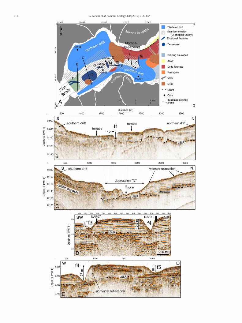
Seismic data allowed identifying different morpho-sedimentaryenvironments. Fig. 3A shows the distribution of the main morpho-sedimentary units outcropping at the seafloor in the whole study area,while Fig. 4A is the same map zoomed in the area of the NafpaktosBay and the Mornos–Drepano sill. The morphology and the seismiccharacteristics of the morpho-sedimentary units will be describedfrom west to east in this section, while our interpretations follow inSection 5.
4.1.1. Nafpaktos Bay and Mornos–Drepano sillThe general morphology of the Nafpaktos Bay is marked by a 2.5 km
wide U-shaped valley striking NE–SW (Figs. 4A and 5A). The valleyforms an 11 km long corridor, ranging in depth from ~40 m to~115 m, i.e. the bottom of the Nafpaktos Bay, and extending from theRion sill in the west to the Mornos–Drepano sill in the east (Fig. 4A).The seismic facies of sedimentary units that crop out in the axis of thisvalley consist of discontinuous, strong reflectors to the west, close tothe Rion straits (e.g. Fig. 4B and C) and sub-parallel continuous reflec-tors to the east (Fig. 4D).
4.1.1.1. Erosive features. Terraces and smaller-scale erosional morphol-ogies are observed in the axis of the U-shaped valley (dark blue featuresin Fig. 4A labeled f1 to f5). In the Rion sill area, the sea-floormorphologyshows two sub-horizontal surfaces (terraces, Fig. 4B) separated by smallmounds and by two elongated depressions. The two terraces are locatedat 62 to 71m bsl. The two elongated depressions are 4 to 12m deep and~100 m wide and they merge toward east (f1, Fig. 4B). About 1 km tothe northeast of the terraces, the seafloor is marked by a large circulardepression named “f2” (Fig. 4A). The depression is 1.6 km wide and35 m deep (Fig. 4C). This erosional feature is carved into a seismic unitmade of high-amplitude chaotic reflections and is limited to the southby a MTD (Fig. 4C). In the eastern half of the Bay, the f3, f4 and f5 ero-sional features have similar characteristics (Fig. 4D and E). They areelongated depressions, 150–300 m wide, about 1 km long and 4–27 mdeep. Depressions f3 and f5 strike E–W,while f4 strikes perpendicularly(Fig. 4A). These three erosional features are incised in a seismic unitessentially composed of parallel, continuous moderate amplitudereflectors (Fig. 4D and E). In the case of f4 and f5, higher-amplitude,sigmoidal reflections are also present on one side of the depression
(Fig. 4E). The dense grid of seismic data acquired in this area showsthat these three depressions are not connected to each other (Fig. 4A).Finally, other erosional features are observed east of the NafpaktosBay, just east of theMornos–Drepano sill (Figs. 4A and 6). Here, the sea-floor shows the following features: a curved N–S striking erosionalscarp, a buried scour, and an active scour, labeled “f6” in Fig. 4A. Bothscours strike parallel to the scarp and are consequently also parallel tothe contour lines (Figs. 4A and 6). The scours are ~200 m wide, about1.7 km long and 6–10 m deep. East of the scours, downslope, the sea-floor is not eroded and sedimentary units composed of strong reflectorsaccumulate on top of the Holocene transgressive surface (Fig. 6).
4.1.1.2. Depositional features. Depositional reliefs, considered as driftdeposits or contourite drifts, are present to the north and south of theU-shaped valley described above (in mid-blue in Figs. 3A and 4A).They form two elongated upward-convex reliefs striking parallel tothe axis of the Gulf: the northern and the southern drifts. The northerndrift is limited to the Nafpaktos Bay. It is 6 km long, 3 km wide and ex-tends from the Rion straits to the Mornos River delta. The seismic unitsthat compose the relief are up to 45 m thick. They onlap the Last SeaLevel Rise unconformity already identified by Beckers et al. (2015)(Fig. 5A, LSLR: last sea level rise). The southern drift is longer than thenorthern one. It extends along 11 km from the Rion straits to the westto 3 km east of the Drepano delta to the east (Fig. 4A). In the NafpaktosBay, this depositional relief is relatively narrow (less than 1 km) andthin (less than 20 m of sediments above deltaic deposits, Fig. 4C). East-ward, east of theMornos–Drepano sill, the southern drift is wider (up to3 km) and also covers the axis of the Gulf in addition to its southernflank (Fig. 4A). This depositional relief is the thickest on the easternflank of the Drepano River delta (at least 50 m of sediments above del-taic deposits, Fig. 7A).
In terms of seismic characteristics, both the northern and the south-ern drifts are composed of moderately strong, continuous parallel re-flectors locally separated by internal unconformities (Fig. 5A).Reflections thin basinward or are truncated at the seafloor (e.g.Figs. 4C, 5A and 7A).
4.1.2. The area from the Mornos–Drepano sill to the Delphic PlateauEast of the Mornos–Drepano sill, the Gulf deepens and widens
(Fig. 1D). Different sedimentary environments can be distinguishedbased on the seismic facies and based on the morphology of thedeposits.
Basin fill deposits are observed in theMornos Canyon, in the DelphicPlateau and in two sub-basins located north of the Mornos Canyon(Fig. 3A). The thickness of these deposits above the last sea level risesurface is 20–50 m in the Mornos Canyon and a few to 30 m in theDelphic Plateau (Fig. 3B). In the sub-basins north of the Mornos Canyon,the LSLR surface has not been identified everywhere. Where this surfacehas been defined, the thickness of basin fill deposits above the latter sur-face is between 20 and 40m. The seismic facies of these deposits consistsof sub-parallel high-amplitude reflections with variable frequencies (e.g.Fig. 8A). Lenses of incoherent reflections are also present (Fig. 8A).
Draping sediments are present on the slopes north of the MornosCanyon and north of the Delphic Plateau, as well as in one regionsouth of the Mornos Canyon, between the southern sediment drift tothewest and the Erineos fan-delta to the east (Fig. 3A). On the northernslopes, sediment thickness above the LSLR surface is lower than 20 mwhile it reaches 50 m on the slopes south of the Mornos Canyon. Theseismic characteristics of these draping units are a lower amplitudeand a better continuity of the reflections in comparison to Basin fill de-posits, in addition to the draped pattern.
Other sedimentary environments are related to the existence ofGilbert-type fan-deltas, already described in details by Piper et al.(1990) and Lykousis et al. (2009). These environments are describedhere as shelves, delta foresets and fan aprons (Fig. 3A). Around theMornos, the Erineos and the Meganitis fan-deltas, the shelf is almost
317A. Beckers et al. / Marine Geology 378 (2016) 312–332
318 A. Beckers et al. / Marine Geology 378 (2016) 312–332

absent (Fig. 3A). Only some narrow shelf remnants (b1 kmwide) existon the side of these deltas, e.g. west of the Erineos fan and in the bay be-tween the Meganitis and the Selinous fan-deltas (Fig. 3A). The shelf iswider around the Selinous and the Marathias fan-deltas, reaching2 km wide.
The slopes that link the shelf edge to the Mornos Canyon or theDelphic Plateau generally consist of two morphosedimentary unitsthat differ by the slope angle: relatively steep delta foresets and lesssteep fan aprons (Fig. 3A). In the Mornos fan-delta, delta foresetsshow different morphologies between the south-western and thesouth-eastern slopes. To the south-west, the foresets extent from thecoast to about 100 m bsl and their slope angle is about 2.5°. Most ofthe foresets in this area are affected by a rotational slump evidencedby the presence of curved growth faults (see seismic profiles in
Lykousis et al., 2009). To the south-east, the foresets extent deeper,reaching the Mornos Canyon at 170–200 m bsl. Their slope is steeper,reaching about 9°. The morphology of this flank of the Mornos delta ismore irregular than the south-eastern flank. Foresets are affected bylandslide head scars as well as numerous gullies (Fig. 3A). The seismicfacies of the Mornos delta foresets is highly variable and encompasssubparralel to chaotic reflectionswith variable amplitudes and frequen-cies. Along the opposite margin, in the Erineos fan-delta, the deltaforesets extent from the coast to a depth of 310–340 m bsl and theirslope angle ranges between 15 and 30°. Foresets are cut by gullies,mainly on the eastern flank of the delta, thatmerges with theMeganitisRiver prodelta (Piper et al., 1990). On the northern flank, foresets aredisrupted by submarine landslide scars (Fig. 3A). Two MTDs related tothese landslide scars outcrop at the seafloor downslope, in the Mornos
Fig. 5. Sparker seismic profile and sediment cores from theNafpaktos Bay. A) Sparker seismic profile showing depositional reliefs interpreted as sediment drifts in the Nafpaktos Bay. LSLR:last sea level rise. Colors represent the potential density anomaly in summer inferred from 6 temperature and salinity profiles (black dots) from theWorld Ocean Database (http://www.nodc.noaa.gov/). Location of the profile in Fig. 3A. B) Logs and radiocarbon ages constrains of the three gravity cores retrieved in the center of the Nafpaktos Bay (for location see Fig. 4A).C) Lithology, X-ray picture and median grain-size of the core NAF05 retrieved in the northern sediment drift. D) Picture of the core NAF10 highlighting the sedimentary unit U2.
Fig. 4.Map view (A) and seismic profiles (B, C, D, E) illustrating the erosional features identified in the Nafpaktos Bay. LSLR = last sea level rise. MTD = mass transport deposit.
319A. Beckers et al. / Marine Geology 378 (2016) 312–332

Canyon (Fig. 3A). Sediment thickness above the LSLR surface is particu-larly huge in the foresets located between the Erineos River mouth andthe Meganitis River mouth, reaching locally 90 m (Fig. 3B). Foresets ofboth fan-deltas are imaged as variable amplitude, continuous parallelreflections (not illustrated here, see Piper et al., 1990 and Lykousiset al., 2009).
Fan aprons form a 2 to 3.5 kmwide band south of the Delphic Plateauand south andwest of theMornos Canyon. These deposits are located be-tween delta foresets, upslope, and basinfill deposits, downslope. They arecharacterizedby a seafloor slope angle of 1.0–1.8° anda seismic facies thatvaries laterally between lenses of low-amplitude chaotic reflections,lenses of high-amplitude hummocky reflections, and wider units of sub-parallel continuous reflections.
Seismic profiles also reveal eleven mounded structures essentiallylocated in the Erineos delta fan apron areas (Fig. 9B and C and mapview in Fig. 3A). The accurate geometry of these reliefs is not constraintby this study, but seismic data suggest that they are about 100 to 750min diameter and 4 to 20 m high. Fig. 9B and C shows seismic profilesimaging the center of two of these mounded features. In both cases,the top of the mound is imaged as hyperboles. Seismic facies howeverdiffer between the twomounds. In Fig. 9B, themounded feature is com-posed of high-amplitude incoherent reflections, similar to the seismicfacies of a MTD outcropping at the seafloor at the same location, aroundthemound. In Fig. 9C, a similar seismic facies is present at depth, but thesediments just below the surface of the mound are imaged as parallelhyperboles, suggesting the existence of stratification.
Fig. 6. Sparker seismic profile showing bedforms and a depositional relief interpreted as resulting from the action of bottom-currents on the eastern slope of the Mornos–Drepano sill.LSLR: last sea level rise. Location of the profile in Fig. 3A.
Fig. 7. A) Sparker seismic profile showing a depositional relief interpreted as sediment drift between the Drepano (to the south) and theMornos (to the north) deltas. LSLR: last sea levelrise. Location of the profile in Fig. 3A. B) Lithology, X-ray picture and median grain size for the core PSA01.
320 A. Beckers et al. / Marine Geology 378 (2016) 312–332
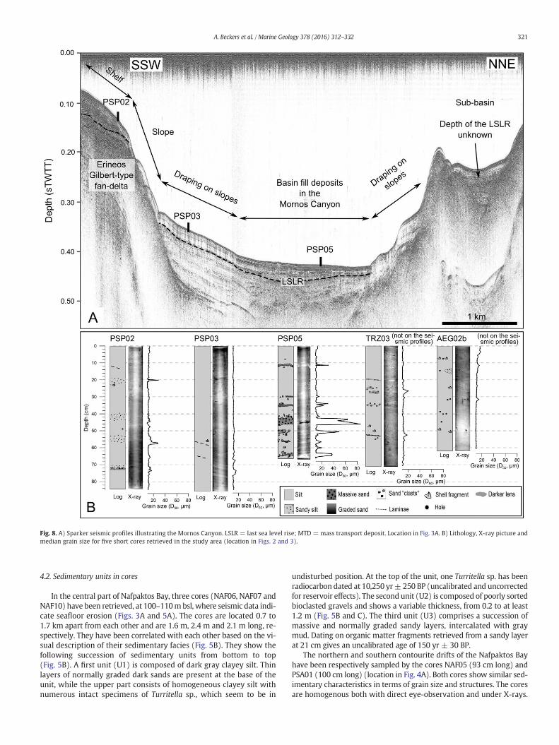
4.2. Sedimentary units in cores
In the central part of Nafpaktos Bay, three cores (NAF06, NAF07 andNAF10) have been retrieved, at 100–110mbsl, where seismic data indi-cate seafloor erosion (Figs. 3A and 5A). The cores are located 0.7 to1.7 km apart from each other and are 1.6 m, 2.4 m and 2.1 m long, re-spectively. They have been correlated with each other based on the vi-sual description of their sedimentary facies (Fig. 5B). They show thefollowing succession of sedimentary units from bottom to top(Fig. 5B). A first unit (U1) is composed of dark gray clayey silt. Thinlayers of normally graded dark sands are present at the base of theunit, while the upper part consists of homogeneous clayey silt withnumerous intact specimens of Turritella sp., which seem to be in
undisturbed position. At the top of the unit, one Turritella sp. has beenradiocarbon dated at 10,250 yr± 250 BP (uncalibrated and uncorrectedfor reservoir effects). The second unit (U2) is composed of poorly sortedbioclasted gravels and shows a variable thickness, from 0.2 to at least1.2 m (Fig. 5B and C). The third unit (U3) comprises a succession ofmassive and normally graded sandy layers, intercalated with graymud. Dating on organic matter fragments retrieved from a sandy layerat 21 cm gives an uncalibrated age of 150 yr ± 30 BP.
The northern and southern contourite drifts of the Nafpaktos Bayhave been respectively sampled by the cores NAF05 (93 cm long) andPSA01 (100 cm long) (location in Fig. 4A). Both cores show similar sed-imentary characteristics in terms of grain size and structures. The coresare homogenous both with direct eye-observation and under X-rays.
Fig. 8. A) Sparker seismic profiles illustrating the Mornos Canyon. LSLR = last sea level rise; MTD = mass transport deposit. Location in Fig. 3A. B) Lithology, X-ray picture andmedian grain size for five short cores retrieved in the study area (location in Figs. 2 and 3).
321A. Beckers et al. / Marine Geology 378 (2016) 312–332

They are composed of light brown mud with a median grain size (D50)between 8 and 18 μm (Figs. 5C and 7B).
Eastward, the cores PSP02, PSP03 and PSP05 sample the small shelfwest of the Erineos fan-delta, the sediments draping the southernflank of the Mornos Canyon, and the basin fill deposits in the MornosCanyon itself, respectively (Figs. 3A, 8). PSP02 (85 cm long) shows analternation of light brown mud and slightly coarser-grained layersthat are not particularly distinguishable on X-ray pictures (Fig. 8B).
Sediment sampled in the core PSP03 (86 cm long) is homogenous tothe naked eye, except a few thin darker laminae (Fig. 8B). Grain-sizeindicates silty sediments and confirms the facies homogeneity. X-raysreveal changes in density at the base of the core giving evidence forsediment stratification (Fig. 8B). PSP05 was retrieved in the MornosCanyon, close to an outcropping MTD resulting from a sediment failureon the Erineos delta slopes (see the map view in Fig. 3A). The corecontains an alternation of seven dark gray, 1 to 4 cm thick massive or
Fig. 9.Map view (A) and Sparker seismic profiles (B and C) showing two mounds in the prodelta of the Erineos River. See the legend of Fig. 3A for the color code of the map.
Fig. 10. Demagnetization plots of the natural remanent magnetization for two representative sediment samples in PSP05 and TRZ03. A) and B): Zijderveld diagrams showing themagnetization vectors at each demagnetization step projected on two orthogonal plans. Black squares correspond to the vertical plan while white squares correspond to the horizontalplan. C) and D): classical demagnetization plots.
322 A. Beckers et al. / Marine Geology 378 (2016) 312–332

normally graded sandy layers, and brownmud intervals (Fig. 8B). Somesandy layers are visible on the X-ray picture, either as high-densitylayer, in white, or in one case as a very low density layer, in black (at44 cm, Fig. 8B).
Farther north, along the northern margin, the core TRZ03 (69 cmlong) has been retrieved in the center of a sub-basin, west of theTrizonia Island (Fig. 3A). The core contains gray-brown mud withsome 1–3mmthick, highly bioturbated sandy layers, difficult to identifyby the naked eye but imaged under X-rays, particularly between 18 and38 cm (Fig. 8B).
The last core, AEG02b (61 cm long), has been taken on the shelf offthe Selinous River mouth (Aigion Shelf, Fig. 3A). This shelf is character-ized by pockmarks and mounds linked to the Aigion Fault (Cotterill,2006). The core contains visually homogenous light brown mud(Fig. 8B). X-rays reveal some bioturbation holes as well as slump-likestructures between 12 and 16 cm (Fig. 8B).
4.3. Mineralogy
Average XRDmineral compositions of TRZ05 and AEG01 are similar.Total clay minerals (mainly kaolinite and illite) represent the largestclass in each core, with 35 and 32% in TRZ05 and AEG01, respectively.In TRZ05, the main other minerals are muscovite (31%), quartz (12%),calcite (8%), and plagioclase (7%). Those three minerals are also themost abundant in AEG01 after clay minerals, with light differencesin concentrations. The other minerals identified in the two cores areK-feldspars and dolomite.
4.4. Remanent magnetization
Demagnetization paths for two samples (cores PSP05 and TRZ03)are illustrated in Fig. 10. The NRM shows two components. The compo-nent defined as the ChRM has been reached after the first steps ofdemagnetization, at 10 mT. The ChRM shows a linear trend towardthe origin on the orthogonal plots. The median destructive field (MDF)of the NRM provides information on the mean coercivity state of thesample, which is a reflection of its grain size and mineralogy (Stonerand St-Onge, 2007). MDF varies between 20 and 38 mT along everycore (PSA01, PSP02, PSP05 and TRZ03, Fig. 11).
Average orientations of the ChRM deduced from Fisher statistics aresummarized in Table 1. In TRZ03, PSP02 and PSA01, the declination ofthe ChRMvaries along core over a range of ~30°. Concerning the inclina-tion of the ChRM, The mean inclination of the ChRM in the cores variesbetween 33 ± 1.1° (PSP05) and 65 ± 2.2° (PSA01) (Table 1).
4.5. AMS
Table 2 presents the AMS parameters averaged for each core. Allsamples show a significant tri-axial anisotropy at the 5% confidencelevel according to the F, F12, and F23 tests (Hext, 1963). Mean valuesof anisotropy (P), lineation (L) and foliation (F) are the largest in thesouthern drift (core PSA01) and the lowest in the Aigion Shelf (coreAEG02b). The shape of the ellipsoid of anisotropy is mainly oblate forspecimens in TRZ03, PSA01, PSP02 and PSP03 (T N 0), while the valuesof T are more scattered in PSP05 and AEG02b, with positive and nega-tive values. The orientation of the Kmax, Kint and Kmin axes givesmore in-sights in the possible depositional processes acting at each site. Thoseaxes are plotted in Fig. 12 in a lower-hemisphere projection, in thecore coordinate system (i.e. without correction). Red symbols representspecimens sampled in a coarser-grained layer while the other colorscorrespond to fine-grained sediments. Their distribution in the sixdiagrams shown in Fig. 12 suggests that the magnetic fabric is similarbetween fine-grained intervals, i.e. the background sedimentation,and coarse-grained layers. AEG02b is the shallowest coring site, at−40 m. Specimen Kmin axes, that theoretically are oriented near thevertical in deep-water hemipelagites not influenced by bottomcurrents,
are scattered with an average inclination of 79° (90° means a verticalKmin). This scattering may be partly explained by the low value of an-isotropy (around 1%). Most of the Kmax axes are subhorizontal andtheir azimuths, even if scattered, show coherent values along core.PSP02 is located at −100 m, on a small shelf on the southern gulfmargin that is sloping to the north at an angle between 5 and 10°.Kmin axes are tilted, with an average inclination of 65°. Kmax axes aresubhorizontal, slightly tilted. Kmax azimuths are very coherent alongcore. In PSP05, in the Mornos Canyon, Kmin axes are subvertical. Kmax
axes also have the same azimuths along core. In the Trizonia sub-basin, core TRZ03, the pattern of anisotropy is intermediate betweenthose of PSP05 and AEG02b. The Kmin axes are subvertical, similarly toPSP05, and the Kmax axes are subhorizontal but more scattered in azi-muth, similarly to AEG02b. In the sediments draping the slopes, corePSP03, Kmin axes are slightly tilted (average inclination = 78°), andKmax axes show the same direction along the core, similarly to the pat-tern of Kmax in PSP05. Finally, PSA01, in the southern sediment driftshows the same AMS pattern as PSP05: Kmin axes are near vertical andthe declination of Kmax does not vary with depth.
Based on the average declination of the ChRM, Kmax axes of fourcores have been oriented with regard to the magnetic north (Fig. 13).Kmax axes show variable orientations relatively to the slope of the sea-floor. They are parallel to the slope direction in the Mornos Canyon(PSP05) and roughly perpendicular (i.e. parallel to the isobaths) in theTrizonia sub-basin (TRZ03). In the southern sediment drift (PSA01)
Fig. 11. Median destructive field of the natural remanent magnetization of the 4 coreswhose characteristic remanent magnetization has been extracted. See Figs. 2 and 3for core location.
Table 1Average orientation of the characteristic remanent magnetization (ChRM). N: number ofsamples; k: precision parameter; alpha95: 95% confidence limit.
Core Dec ChRM (°) Inc ChRM (°) N k alpha95
TRZ03 285 50 30 176 2PSA01 210 65 45 106 2.1PSP02 119 45 38 41 3.7PSP05 177 33 29 606 1.1
323A. Beckers et al. / Marine Geology 378 (2016) 312–332

and in the Erineos Shelf (PSP02), Kmax orientation seems to be obliquewith regard to the slope direction.
4.6. Oceanographic data
The potential summer water density anomaly in the NafpaktosBay increases from the sea surface to about 80 ms TWTT (−60 m) andstabilizes below (Fig. 5A). This pattern essentially results from an expo-nential decrease in temperature with depth (Fig. 14A). Salinity variesvery few with depth, between 38.2 and 38.6 psu. One maximum is ob-served at a depth of about 50 m (Fig. 14B).
Both the Mornos River sediment plume in March 2006 (Fig. 15A)and the Fonissa River sediment plume in February 2014 (Fig. 15B) aredeviated toward the east (location of the rivers in Fig. 1C). This indicatesthe existence of significant surface currents flowing eastward duringthese two periods.
5. Interpretations
5.1. Bottom-current related morphologies and shallow water contouritedrifts
5.1.1. Erosional featuresSeveral observations support that the wide U-shaped valley located
in the Nafpaktos Bay and on the Mornos–Drepano sill is an area ofseafloor erosion, or locally sediment non-deposition. The most obviousevidence is the reflectors truncation observed on the flanks of the valleyin several seismic profiles (e.g. Figs. 4C and 5A). Another argument infavor of a significant erosion of Holocene sediments is the low thicknessof Holocene deposits revealed by the isopach map in the center of theNafpaktos Bay (10–15 m of Holocene sediment) as well as in theMornos–Drepano sill (5–10m of Holocene sediment) (Fig. 3B). Besides,the analysis of the cores NAF06, NAF07 and NAF10 confirms the veryrestricted accumulation of sediments (locally less than 1m) in the centerof the Nafpaktos Bay since about 10 ka BP (uncalibrated). In the Rionstraits area,most seismic units outcropping at the seafloor are interpretedas relatively coarse-grained pre-Holocene sediment (blue area in Fig. 3B).The area affected by seafloor erosion corresponds to the area wherestrong currents have been reported (Fig. 1C). It is consequently proposedthat bottom currents are a major control on the seafloor morphology inthe Nafpaktos Bay and Mornos–Drepano sill areas.
The smaller erosional features f3, f4 and f5 are interpreted as furrows(Fig. 4A). The arguments for this interpretation, rather than an interpre-tation in favor of channels, are their small depth, the absence of levees inmany cases and the fact that they are disconnected from each other. Thepresence of furrows indicates the existence of bottom currents, and par-ticularly the role of secondary helical circulation in the boundary layerof the bottom currents (Flood, 1983). The depression f2 may resultfrom another type of secondary circulation, or from the action of thebottom-currents itself, considering the wide spatial extent of thedepression (Fig. 4A and C). The erosional feature f1 is locally carved ina pre-Holocene substratum (Fig. 4B). It has been interpreted byPerissoratis et al. (2000) as a fluvial outlet channel of the Lake Corinth,which occupied the Gulf during Quaternary lowstands. Finally, it is pro-posed that the curved scarp and the scours located just east of theMornos–Drepano sill (Fig. 6) result from turbulence that develops at
the exit of the sill due to the sudden increase in seafloor slope angle.The scarp may also initially result from a slope failure (see a more de-tailed discussion about these features in Section 5).
5.1.2. Depositional featuresBased on their convex morphology, on the seismic facies and on
their location along an area influenced by bottom currents, it isproposed that the two depositional reliefs that occur in the north andsouth of the Nafpaktos Bay, around the Drepano River delta andeast of the Mornos–Drepano sill, are shallow-water contourite drifts(Fig. 4A). Cores NAF05 and PSA01 give clues on the nature of these sed-iment bodies. Both cores show that the seismic facies of the two sedi-ment drifts represents, at least for the upper parts of the deposits,homogenous, structureless muddy sediments (Figs. 5C and 7B). Thespatial configuration of the two sediment drifts indicates that thesediments essentially accumulate in the north of the Nafpaktos Bay(northern sediment drift, Fig. 4A) and east of the Drepano delta (south-ern sediment drift, Fig. 4A), which probably creates a protected areawhere sediment deposition is possible.
In the Mornos–Drepano sill area, a strong N–S asymmetry in sedi-mentary processes exists (Fig. 7A). To the north, the slope is composedof unstable coarse-grained sediments forming the Mornos delta foresetbeds, while to the south, the thick southern sediment drift develops ontop of deltaic deposits. East of the Mornos–Drepano sill, Holocenedeposits are also interpreted as sediment drifts because of the wavypattern of the seafloor and the underlying reflections, adjacent to twoelongated erosional features (Fig. 6).
No other depositional relief or erosional bedform possibly resultingfrom the action of bottom currents has been identified east of the south-ern sediment drift (Fig. 4A).
5.1.3. Possible direction of bottom currents that generate erosive anddepositional features
The spatial distribution of sediment drifts and erosional featuresallow to estimate the average orientation of bottom currents in theGulf of Corinth during the Holocene. In the Rion sill, the absence of sed-iment drift suggests that bottom currents flow across the entire strait. Inthe Nafpaktos Bay, the asymmetry between the well-developed north-ern drift and the narrower southern drift shows that bottom currentsflow closer to the south-eastern coast, following the deepest part ofthe Nafpaktos Bay. The direction of the flow(s) in this area is conse-quently NE–SW and/or SW–NE. Eastward, bottom-currents cross theMornos–Drepano sill and are responsible for the development ofsediment drifts on the southern flank of the Gulf as well as in the Gulfaxis, on the eastern slope of the sill.
5.1.4. Sedimentary units at the bottom of the Nafpaktos BayThe three cores retrieved in the center of the Nafpaktos Bay (NAF06,
NAF07 andNAF10, Fig. 5) give clues to interpret the different seismic fa-cies in terms of sediment characteristics, sedimentary processes, andages of seismic units. Three sedimentary units (U1, U2, U3) have beendefined and are interpreted as follow. In Unit 3, which has only beenfound in NAF10, the alternation between fine-grained intervals andsandy layers (Fig. 5B and D) could be interpreted either as fine-grained hemipelagites interbedded with thin-bedded turbidites/debrites or as contourites. Indeed, the seafloor relief and the seismic
Table 2Averaged results (mean ± standard deviation) of the anisotropy of magnetic susceptibility measurements. See the text for the description of the parameters.
Core N Bulk MS (10−6 SI) L F P T Dec Kmax (°) Conf angle (°) Inc Kmin (°) Conf angle (°)
AEG02b 25 264 ± 32 1.005 ± 0.002 1.006 ± 0.003 1.011 ± 0.004 0.052 ± 0.418 276 20.6 79 15.7TRZ03 23 207 ± 29 1.006 ± 0.002 1.011 ± 0.004 1.017 ± 0.004 0.286 ± 0.281 317 24.3 85 7.9PSP05 34 250 ± 40 1.013 ± 0.003 1.012 ± 0.007 1.025 ± 0.008 −0.102 ± 0.324 82 7.9 81 4.3PSP03 12 296 ± 25 1.010 ± 0.003 1.018 ± 0.008 1.028 ± 0.010 0.257 ± 0.253 89 4.6 78 3PSA01 11 364 ± 49 1.016 ± 0.003 1.026 ± 0.004 1.043 ± 0.007 0.237 ± 0.080 271 4.8 89 2.3PSP02 47 214 ± 27 1.009 ± 0.004 1.014 ± 1.005 1.023 ± 0.005 0.232 ± 0.360 91 9.5 65 5.9
324 A. Beckers et al. / Marine Geology 378 (2016) 312–332

Fig. 12. Unoriented anisotropy of magnetic susceptibility of recent sediments in 6 cores from the western Gulf of Corinth. The axes of anisotropy are plotted in a lower hemispherestereographic projection. Red dots correspond to cubes sampled in coarser-grained layers (sand) interpreted as event deposits while the other colors (white, gray, black) correspondto cubes sampled in fine-grained intervals. See Figs. 2 and 3 for core location.
325A. Beckers et al. / Marine Geology 378 (2016) 312–332

facies characteristics in the center of the Nafpaktos Bay are compatiblewith the existence of both turbidity currents coming from the Mornosprodelta slopes and with contourites deposited by bottom currents in
the axes of the Bay. Moreover, distinguishing contourite facies fromturbidite facies in sediment cores still suffer from a lack of unambiguousand commonly accepted diagnostic criteria (e.g. Rebesco et al., 2014).
Fig. 13.Average orientation of maximum-susceptibility axes (Kmax) for 4 short gravity cores in thewestern tip of the Gulf of Corinth. The cores are 0.65m to 1.0m long and the anisotropyofmagnetic susceptibility has beenmeasured on 11 to 47 samples from each core. In each core, Kmax axes follow a unique direction (see Fig. 12) that has been re-orientedwith respect tothe magnetic north based on the declination of the characteristic remanent magnetization. The bathymetry has been interpolated from the grid of seismic data (see the grid in Fig. 2).
Fig. 14. A) temperature, B) salinity profiles in the center of the Nafpaktos Bay from theWorld Ocean Database (http://www.nodc.noaa.gov/). Plots correspond to station IDs 705, 823, 839and 871 (see the World Ocean Database for their accurate locations).
326 A. Beckers et al. / Marine Geology 378 (2016) 312–332

The modern age of terrestrial organic matter sampled in this unit(younger than 1670 AD after calibration) indicates a recent age forU3, and consequently no significant recent seafloor erosion in thisarea. In comparison, the absence of U3 in NAF06 and NAF07, locatedin the deepest part of the Nafpaktos Bay, supports a more intenseseafloor erosion in that area. Unit 2, which has been observed inthe 3 cores (Fig. 5B and D), is interpreted as a transgressive deposit.The 14C dating of the Turritella sp. specimen in the Unit 1 belowimplies that the transgressive episode occurred after ~10 ka BP(uncalibrated and uncorrected from reservoir age). The clayey–silty, Turritella sp.-rich Unit 1 including thin dark sandy layers,interpreted as thin turbidites, would have been deposited in shallow-water (depth b 100 m) marine/lagoon environment, protected frombottom currents or swell. Indeed recent Turritellidae live in marine orbrackish environments, most commonly in waters less than 100 m deep(Allmon, 1988).
The following link between the sedimentary units identified inthese 3 cores and the morpho-sedimentary features highlighted inthe seismic profiles is proposed. In the center of the Nafpaktos Bay,the transgressive sedimentary unit U2 could correspond to the “un-conformity 1” identified locally around the furrow f3 (Fig. 5A). The400 m-wide buried channel located in the same area (Fig. 5A)could also correspond to the same transgressive event, whichwould have occurred after ~10 ka BP (uncalibrated and uncorrectedfrom reservoir age). The nature of this erosional event will bediscussed in Section 6.1.
5.2. Othermorpho-sedimentary features and related sedimentary processes
Besides bottom-current related features, there is a large variety ofdepositional environments in the study area: basin fill, draping onslopes, Gilbert-delta related deposits, MTDs and mounded structures.Results of this study allow proposing some new interpretations fortwo of them: the basin fill in the Mornos Canyon and the moundedstructures.
5.2.1. The basin fill in the Mornos CanyonIn the Mornos Canyon, the Holocene infill imaged as high-amplitude
reflections (Fig. 8A) is interpreted to representfine-grainedhemipelagitesinterbedded with coarser-grained sediment density flow deposits. Thisinterpretation is supported by the core PSP05,which shows such an alter-nation in the central part of the Mornos Canyon (Fig. 8B). Twomain sed-iment sources are proposed for the sediment density flow depositsrecorded in the Mornos Canyon. First, at the western tip of the MornosCanyon, the numerous gulliesmapped on the eastern flank of theMornosdelta (Fig. 3A) suggest that at least some of these sediment density flowscould have been turbidity currents resulting from sediment failures onthe flanks of this delta. Then, south of the Mornos Canyon, the gullieslocated between the Erineos and Meganitis delta foresets, as well as thetwo MTDs located at the base of the Erineos prodelta slope highlightanother sediment density flow origin, from the southern coast (Fig. 3A).Finally, we observed no gullies or channel connecting the deltas on the
Fig. 15. Satellite imagery of river sediment plumes in the Gulf of Corinth deflected bymarine currents. A)Mornos River, 27thMarch 2006; B) Fonissa River, 15th February 2014. Location ofthe river mouths in Fig. 1C. Source: Google Earth©.
327A. Beckers et al. / Marine Geology 378 (2016) 312–332

northern coast (i.e. the Marathias and Sergoula River fan-deltas) tothe Mornos Canyon. This suggests that the perched topography in thenorthern shelve traps most of the gravity flows that cannot reach thebasin floor.
5.2.2. The mounded featuresFarther east, seismic data have highlightedmounded features essen-
tially located in the fan area of the Erineos prodelta (Fig. 3A). Two hy-potheses are proposed for the genesis of these forms: (i) they couldrepresent the summits of mud volcanoes caused by overpressure, or(ii) they may be large sediment blocks that failed from the steep deltaforesets on the southern coast, e.g. the Erineos delta. The first mound,in Fig. 9B, is located in the center of a MTD that crops out at the seafloor,and has the same hummocky reflector pattern as the MTD. This wouldargue in favor of the sediment block hypothesis. In Fig. 9C, the secondmound seems to result from the deformation of the upper sedimentaryunit, rather than from a lateral advection of material at the surface. Thisis an indication that themoundmay be a diapiric structure rather than asediment block. Sedimentary loading due to rapid sedimentation(Dimitrov, 2002) is proposed as a possible driving force for this possiblemud diapirism. Indeed, the thickness of Holocene sediments reaches90 m in the foresets of the Erineos delta (Fig. 3B). This value is thehighest value observed in our data in the study area. Such a sedimentaryloading, associated with frequent seismic activity, is proposed to haveremobilized under-compacted pre-Holocene MTDs that would havebeen deposited below the Erineos delta foresets. A last argument infavor of the diapiric origin is the spatial arrangement of the mounds.All are located in the gently dipping fan area, at a similar distancefrom the steep slopes of the Gilbert-type Erineos and Meganitis fan-deltas. This regularity is particularly clear from the 3D view of the sea-floor in Lykousis et al. (2009) (their Fig. 5, p. 814) and is difficult to ex-plain in the case of large rafted blocks, that are expected to travel alongvariable distances. Moreover, it seems likely that the specific conditionsneeded for the development of mud diapirs, i.e. high loading and thepresence of liquefiable material, implies that mud diapirs are not dis-tributed randomly. In summary, these observations are more favorableto the “mud volcanoes” hypothesis than to the “rafted blocks” hypothe-sis, for all the mounded structures.
5.3. Properties of drifted sediments compared to other deposits
Based on the sedimentary data from the cores presented above, wecompared the sediment properties between muddy contourites sam-pled by the cores NAF05 and PSA01 on one hand to the backgroundfine-grained sedimentation in other depositional environments on the
other hand (cores PSP02, PSP03, PSP05, TRZ03 and AEG02b). The lattergroup of cores contains cores from “basin fill” (PSP05, TRZ03),“draping on slopes” (PSP03) and “shelf” (PSP02, AEG02b) environ-ments. The aim was to identify some properties that can be usedto discriminate muddy contourite from other kinds of fine-graineddeposits (likely hemipelagites) in sediment cores.
5.3.1. Grain-size distribution, color and structureSediment color (gray-brown) and structure (almost no visible struc-
ture) are very similar in fine-grained interval of all the cores (cfr. thelogs of the different cores in Figs. 5C, 7B and 8B). Regarding grain-size,the comparison of the D50 measured in the contourite drifts (coresPSA01 and NAF05) and in the muddy intervals of the other coresshows that grain size is very homogenous with a median grain-sizebetween 8 and 15 μm (Fig. 16A). Only two samples from PSA01, in thesouthern drift, are lightly coarser-grained than the samples from theother coring sites (D50 of 16 and 17 μm, Fig. 16A). A slight differencein grain-size distribution between contourites and the other muddydeposits stands out from the comparison of sorting (Fig. 16B). Indeed,samples from PSA01 appear on average lightly less well sorted (higherSorting Index) than samples from the other sites. Therefore, the recentcontourites deposited on the drifts do not strongly differ from sedi-ments that make up the background, likely hemipelagic, intervals inthe other coring sites.
5.3.2. Magnetic properties
5.3.2.1. Median destructive field and characteristic remnant magnetization.In order to interpret the AMS measurements, it is first necessary tocheck that the measurements of the NRM can be used to estimate theorientation of the magnetic north in each core. This step is presentedbelow based on the interpretation of the ranges of variations of theMDF, of the ChRM declination and of the ChRM inclination.
The range of values for theMDF between 20 and 40mT suggests thatthe carrier of the remanence is ferrimagnetic, most likely magnetite(Fig. 11). The low variability of the MDF in each core also suggeststhat the carrier of the remanence in each core does not strongly varywith depth (Fig. 11). The inclination of the present geomagnetic fieldin the Gulf of Corinth area is about 54° (http://magnetic-declination.com). Assuming a possible inclination error of about 10° due to possiblenon-vertical coring, the ChRM inclination of TRZ03, PSP02 and PSA01can consequently be considered as more or less normal (Table 1).Only the core PSP05 shows an average inclination value (33 ± 1.1°)that is different from the inclination of the present-day geomagneticfield. The range of variation of the declination in TRZ03, PSP02 and
Fig. 16.Median grain-size (A) and sorting (B) for recent inter-event fine-grained sediments in 7 short cores from the western Gulf of Corinth. At least 10 samples have beenmeasured ineach core (circles). The black dots represent the median (left) or the mean (right) of all samples from each core. See Figs. 2 and 3 for core location.
328 A. Beckers et al. / Marine Geology 378 (2016) 312–332

PSA01 (~30°, not shown) is interpreted as reflecting, at least partially,the secular variations of the geomagnetic field that induced a shift ofthe declination of about 20° in the last 3 centuries, which is approxi-mately the time span recorded in the studied cores (Beckers et al.,2013). This is not the case for PSP05, located in the Mornos Canyon,with only a shift of about 5° for the declination.
In summary, the data support that in TRZ03, PSP02 and PSA01, theChRM orientation may correctly reflect the orientation of the geomag-netic field at the time of particle deposition. It is consequently proposedto use the average ChRM declination of each core to reorient ASM dataregarding themagnetic north. For the core PSP05 in theMornos Canyon,the ChRM declination and the ChRM inclination cannot be fully ex-plained by a simple model assuming that only the geomagnetic fieldhas controlled particles orientation. However, the ChRM is here usedto roughly estimate the direction of the magnetic north at each coringsite, rather than to accurately highlight past variations of the geomag-netic field. It is consequently proposed based on the presented resultsthat the average ChRM declination deduced for the PSP05 site is also areliable indication of the orientation of themagnetic north, but probablywith a lower accuracy.
5.3.2.2. AMS parameters. The strong internal coherence between theKmax axes declination inside the six cores suggests that the grains arenot randomly oriented at these coring sites (Fig. 12). It is proposedthat bottom currents are responsible for this alignment of Kmax axes inthe contourites, as well as in the muddy sediments in the other coringsites, interpreted as hemipelagites according to their seismic facies.More-over, concerning the cores from “basinfill” (PSP05 and TRZ03) and “shelf”environments (PSP02 and AEG02b), the similarity between AMS ellip-soids of samples from the fine-grained intervals and from sandy layers(Fig. 12) suggests that bottom currents also influence the orientation ofthe grains transported and deposited by sediment density flows. This isespecially the case in PSP05, where the sandy layers are up to 4 cmthick and consequently fully fill the cubes used for the sampling.
The geographic orientation of the Kmax axes is another parameterthat can provide information about a possible influence of bottomcurrents on depositional processes. The Kmax axes often are assumedto beparallel to the current direction. However, if the seafloor is not hor-izontal, grains can roll on the seafloor by gravity so that the Kmax orien-tation is controlled by the slope direction (Kmax parallel to the isobaths).In the sub-basin west of the Trizonia Island (core TRZ03), average Kmax
orientation is parallel to the isobaths. This orientation of the grains mayresult from gravity-induced rolling or contour-parallel bottom currents.In the Mornos Canyon (core PSP05), the Kmax orientation follow thecanyon axis and suggests the existence of a bottom current oriented inthis direction. Turbidity currents could be invoked as well (e.g. Shoret al., 1984), but the fact that all samples show the same Kmax orienta-tion whatever the sedimentary unit they come from (fine-grained“background” intervals or sandy event deposits) suggests a continuousprocess, such as bottom-currents, rather than occasional turbidity cur-rents. In the southern sediment drift (PSA01), Kmax orientation makesan angle of about 60° with the isobaths, which also suggests a possibleinfluence of west–east bottom currents. Finally, in the Erineos deltaarea (PSP02), the seafloor relief is not well constrained so that thecomparison between the orientation of the isobaths and the orientationof the Kmax axes is not possible.
6. Discussion
The western tip of the Gulf of Corinth shows a large diversity ofdepositional and erosional features, in a relatively small area. These fea-tures result from the interaction of different sedimentary processes,which are discussed hereafter Section 6.1. In Section 6.2, different as-pects linked to the existence of shallow water sediment drifts in theGulf of Corinth are discussed, based on the interpretations presentedabove combined with results from the literature. Finally, Section 6.3
summarizes the data that are available for a better understanding ofthe water circulation pattern in the Gulf of Corinth.
6.1. Sedimentary processes and their timing at the western tip of the Gulfof Corinth
Different sedimentary processes are proposed to be active at thewestern tip of the Gulf of Corinth, between the Rion and the Mornos–Drepano sills. Currents divert river plumes (over- or interflows) andallow thebuilding of shallow-water sediment drifts around theDrepanodelta and on the margins of the Nafpaktos Bay (northern and southernsediment drifts). Besides, currents are eroding the bottom of theNafpaktos Bay, the Mornos–Drepano sill, and the base of the drifts.Secondary helical circulations in the Nafpaktos Bay induce the forma-tion of furrows (Fig. 4). East of theMornos–Drepano sill, scarps possiblyrelated to submarine landsliding (see our arguments in Section 6.2.3.)are reworked by bottom currents, and scours form at the foot of thescarp (Fig. 6). Downslope, another sediment drift develops and is later-ally connected to the southern drift (Fig. 6). The absence of sedimentdrift on the southeastern flank of the Mornos delta would result fromits location in the axis of the Nafpaktos Bay that would orient the cur-rents along the Mornos delta foresets, preventing the deposition of rel-atively fine-grained sediments. The frequent submarine landslides thataffect the delta foresets also contribute to the absence of sediment driftat this location. East of theMornos–Drepano sill, gravitational processessuch as submarine landslides and turbidity currents seem to play a larg-er role in sediment transport than bottom currents, as proposed byFerentinos et al. (1988) and Lykousis et al. (2007a). However, the specif-ic magnetic fabric highlighted in the Trizonia sub-basin, in the MornosCanyon and in the Erineos and Aigion shelves (Fig. 12) suggests thatbottom currents influence the sedimentation in various places of thewestern Gulf of Corinth by reorienting the grains during or shortlyafter their deposition. The directions of the Kmax axes in the Trizoniasub-basin and in the Erineos Shelf (Fig. 13) also support the existenceof contour-parallel bottom currents in these areas.
Moreover, data collected in the Nafpaktos Bay provide new informa-tion about the connection of the Corinth Lake and the adjacent Gulf ofPatras area with the Mediterranean Sea during the last sea level rise.In the center of the Nafpaktos Bay, below 10 to 20 m of sediments, anunconformity has been correlated to a transgression surface that iswell imaged in the northern part of the Bay (Fig. 5A; Fig. 7 in Beckerset al., 2015). This onlap surface clearly reflects an increase in the waterlevel, and probably corresponds to the transition between a non-marine and a marine environment that has been dated at ca. 12 ka BPat the eastern tip of the Gulf (Collier et al., 2000). A younger transgres-sive unit, up to 1.2m thick, is observed in the three cores retrieved in thecenter of the Bay (sedimentary unit U2, Fig. 5B andD), aswell as in high-resolution seismic profiles (seismic unconformity 1, Fig. 5A). U2 locallycrops out in the sea bottomand has a basal age of 10.2 ka BP (uncalibrat-ed) according to the new radiocarbon age presented in this study. Awide paleo-channel is observed in the seismic lines close to the locationof those cores (Fig. 5A). It could result from the same transgressiveevent as U2. Consequently, our results suggest that the last transgres-sion occurred in two different pulses in the Nafpaktos Bay. A firstphase would have occurred at ca. 12 ka BP (uncalibrated, from Collieret al., 2000), while a second phase would have deposited U2 after10.2 ka BP (uncalibrated, this study). It is proposed that after the firstpulse at ca. 12 ka BP, fine-grained sediments (U1) accumulated in theBay at a sufficient rate to maintain a shallow water environment.Then, an increase in the rate of relative sea level rise would havebeen responsible for the second transgressive pulse observed in theNafpaktos Bay (U2). The ongoing sea level rise finally reached a suffi-cient elevation above the Acheloos–Cape Pappas sill (which is 50–55 m deep if the Holocene surface veneer of sediment is subtractedfrom the present depth, Fig. 1B) and the Rion sill (62m deep), so a com-plete marine connection occurred and the sediment drifts started to
329A. Beckers et al. / Marine Geology 378 (2016) 312–332

develop after 8–9 ka BP. The later interpretation is also in agreementwith sedimentological record in the middle of the Gulf sampling theLacustrine–Marine transition (Moretti et al., 2004). The first marine in-flux is attested by the precipitation of aragonite needles (Van Welden,2007) and occurred at ca. 11.3 ka BP (uncalibrated age derived fromCampos et al., 2013a). The full connection and the establishment ofthe present sedimentological regime occurred later, around 10.4 ka BP(Campos et al., 2013a), and is marked by an increase in magneticsusceptibility and the occurrence of frequent turbiditic flows (VanWelden, 2007).
6.2. Contourite characteristics
6.2.1. Possible sediment sourcesSedimentological characteristics of the Gulf of Corinth contourites are
very similar to the fine-grained sediments interpreted as hemipelagitesin the coring sites east of the drifts. This suggests that the sedimentsources of the drifts are local river sediment plumes, i.e. the Mornos andthe Drepano rivers. River plumes in this area are sometimes stronglydeflected by currents (Fig. 15). Moreover, in the time scale of the Holo-cene, the thickness of the southern sediment drift is larger east of theDrepano River delta than west of this delta, in the Nafpaktos Bay. Thisasymmetry consequently suggests that the net sediment transport is ori-ented toward the east. Apart from the direct input from river sedimentplumes (distributed as overflows or interflows), the possibility that sedi-ments eroded in the center of the Nafpaktos Bay contribute to the sedi-ment accumulation on the drifts cannot be ruled out.
6.2.2. Diagnostic criteriaApart from the typical shape of the sediment drift depositional
reliefs, the criteria proposed here to discriminate contourites fromother fine-grained deposits in the Gulf of Corinth environment are thehigh homogeneity under X-rays, the higher AMS (higher value of P,Table 2), and, for some samples from the core PSA01, a weaker grain-size sorting (Fig. 16). A higher sorting (i.e. lower Sorting Index, closeto 1) was expected for the drift sediments compared to “classical”hemipelagites. This counterintuitive value for the sorting may resultfrom the proximal location of the core PSA01 regarding the DrepanoRiver mouth (Fig. 4A). Indeed, if the sediment sources of the drifts arethe local river plumes, as it is proposed, then river discharge fluctuationsduring floods may weaken the sorting of sediments deposited nearthe river mouth. Furthermore, the likely strong variability in currentstrength through time in the Nafpaktos Bay may also lead towarda weaker sorting in the sediment drifts compared to “classical”hemipelagites. Based on these criteria, the identification of similarshallow-water muddy sediment drifts in the ancient records canprovide indications on the paleogeography of the system. For exam-ple, looking for similar sediment drifts in exhumed rift sediments,such as those covering the north of the Peloponnese, may give indi-cations on ancient water depth, bottom currents, and on a possibleconnection to the open sea.
6.2.3. Comparison with other sediment driftsAccording to recent classifications of sediment drifts, the northern
and southern sediment drifts located in the Nafpaktos Bay belong tothe “plastered drifts”, which develop in deep oceans on gentle slopesswept by relatively low-velocity currents (e.g. Hernandez-Molinaet al., 2003; Rebesco et al., 2014; Pérez et al., 2015). Comparing thesedimentary features identified in this study to bottom-current relatederosional and depositional features described elsewhere helps to distin-guish the effects of bottom currents from those of gravity-driven pro-cesses, and also gives us an idea about the type of circulation patternthat could be responsible for the formation of the sediment drifts inthe Gulf of Corinth.
In this way, the curved scarp located just east of the Mornos–Drepano sill and the sediment drift located downslope (eastern tip of
the southern sediment drift, Fig. 6) are similar to morphologies de-scribed in the SW Adriatic margin (Verdicchio and Trincardi, 2008b,e.g. their Fig. 4). These authors interpret seaward-concave moats in ashelf-edge area to initially result from sediment failure, reworked after-ward by bottom currents flowing parallel or oblique to the depth con-tours. Considering the numerous slope failures and MTDs locatednorth and west of the Mornos–Drepano sill, it is proposed that thesame model may hold for this area, i.e. that the curved scarp initiallyresults from landsliding and has been subsequently reshaped by bottomcurrents.
The northern and southern sediment drifts identified in theNafpaktos Bay on both sides of the Gulf axis show similarities to driftsdescribed in the Gulf of Izmit, Sea of Marmara (Kuscu et al., 2002). Thetwo gulfs have a similar shape and comparable widths and depths, soit is relevant to compare both systems. The oceanography of the Gulfof Izmit is better known than that of the Gulf of Corinth. It has a perma-nent two-layered water system connected to the water circulation ofthe Sea ofMarmara (Balkis, 2012). The upper layer consists of less salinewater from the Black Sea, while the lower layer originates from theMediterranean Sea. The two layers flow in different directions depend-ing on the season, and are probably responsible for the establishment ofthe drifts. In the Gulf of Corinth, it is unlikely that the bottom currentsare driven by such strong thermohaline gradients. Indeed, publishedCTD data does not highlight any permanent change in water tempera-ture or salinity along vertical profiles that could be interpreted as a sim-ple and permanent thermohaline circulation (Poulos et al., 1996).
Finally, a similar comparison can be donewith plastered drifts in theAlboran Sea, east of the Strait of Gibraltar (Ercilla et al., 2015). There, themorphology of plastered drifts located on the Spanish and theMoroccanslopes is also very similar to the one of the drifts presented in this study.Their geometry has been explained by the near-bottom layer distri-bution of the Mediterranean water-masses bounded by the mostpronounced density contrasts (Ercilla et al., 2015). Although thespatial scales differ between the Gulf of Corinth and the AlboranSea, this suggests that the water circulation at the entrance of theGulf of Corinth also involves superimposed water-masses withdifferent densities and that such a circulation, permanent or not,governs the general physiography.
6.3. Possible circulation patterns and mechanisms for the currents at theentrance of the Gulf of Corinth
The morphology of the Gulf of Corinth is somewhat similar to theone of a fjord, with a deep depression connected to the open seathrough a shallow sill. The typical water circulation in a fjord consistsin a brackish outflow on the surface above a deeper compensation cur-rent (Farmer and Freeland, 1983). Besides this simplemechanism, otherprocesses can contribute to the water circulation such as tides, winds,and turbulence. By combining the results of this study with previousworks, it is possible to propose some hypothesis about the circulationpattern at the entrance of the Gulf of Corinth that could explain thepresence of sediment drifts, and to discuss the influence of the possibledrivingmechanisms.Despite the low tidal range in theMediterranean Sea(average mean tidal range of 15 cm for the Gulf of Corinth, Tsimplis,1995), models show that tides are responsible for strong currents in theRion Straits exceeding 1 m s−1 (Fourniotis and Horsch, 2010, 2012).This velocity is sufficient to erode and transport silt- and sand-size parti-cles (Hjulstrom, 1935). Tidal currents can consequently be invoked for thetransport and the deposition of the silt-size particles from the sedimentdrifts. Because the Gulf of Corinth is closed at its eastern tip, the existenceof tidal currents in the Rion Straits area implies that a secondary currentflows simultaneously in the opposite direction. Fourniotis and Horsch's(2012) modeling study suggests that during summer flood tide con-ditions an upper current flows toward the Gulf of Corinth on top of astronger bottom current flowing toward the west. Such a two layersmodel fits with the eastward deviation of the Mornos and the Fonissa
330 A. Beckers et al. / Marine Geology 378 (2016) 312–332

rivers sediment plumes observed on satellite images in March 2006 andin February 2014, respectively (Fig. 15).
This simple two layer circulation model is challenged by CTDprofiles acquired between June and August in the Nafpaktos Bay.The CTD shows a slight increase in salinity at −50 m (Fig. 14B),suggesting more complicated water stratification in this area withpossibly 3 different water masses during summer time. Similarincrease in salinity has been observed between −125 m and−175 m in the Gulf of Corinth and has been interpreted as aninput of the more saline Ionian Sea waters over the Rion sill(Anderson and Carmack, 1973; in Poulos et al., 1996). This interpre-tation supports the occurrence of a three layer flow in the NafpaktosBay, the intermediate one flowing toward the Gulf of Corinth (at 30–70 m bsl) while the upper and the lower water masses (at 0–30 and70–115 m bsl) would flow in the opposite direction (Fig. 14B). Thismore complex circulation pattern during summer time is not incom-patible with a two layers circulation during the other periods that isresponsible for the river plume deflection.
Finally, the inferred strong turbulence that occurs at the entrance ofthe Gulf of Corinth, in the Nafpaktos Bay, must disturb a two or threelayer circulation pattern. The particular conditions leading to turbulenceneed to be further studied. Similarly, the presence of north–southtrending scours in the eastern slope of the Mornos–Drepano sill(Fig. 6) also suggests the occurrence of turbulent flow or lee waves inthis area. Such flow behavior could result from the abrupt increase inwater depth east of the sill (e.g. Farmer and Freeland, 1983).
In summary, a definitive circulationmodel at the entrance of theGulfof Corinth cannot be established with the present data that representsdifferent time-scales. Sedimentological observations give indicationsabout the average conditions during the last few thousand years,while the modeling exercises in the Gulf of Patras (Fourniotis andHorsch, 2012), satellite images from the Gulf of Corinth (this study)and CTD profiles represent specific conditions in terms of tide, wind, sur-face temperature, etc. Seasonal variations in tidal amplitudes, winds andwater density gradients between the Gulf of Corinth and the Ionian Seaare not well constrained and would influence the circulation pattern.Continuous long term current meter measurements are necessary tounderstand the complexity of the flow pattern.
7. Conclusion
A dense grid of high-resolution seismic profiles reveals the existenceof shallow-water sediment drifts in the Gulf of Corinth. The drifts devel-oped at the entrance of the Gulf during the Holocene mainly on bothsides whereas various erosional bedforms are documented in its centralpart. The thickness of the drifts reaches at least 50 m and coringindicates that drifts are composed of homogenous bioturbatedmud in their upper part. A comparison between sediments sampledin the drift and fine-grained sediments sampled at different loca-tions in the Western Gulf of Corinth shows that recent contouritesand hemipelagites have similar properties in terms of color, struc-ture, grain size distribution and magnetic fabric. The magnetic fabricsuggests an influence of bottom currents on grains orientation in thedrift, and also in the deposits initially interpreted as hemipelagites.The presented data highlight the difficulty to identify ancient sedi-ment drifts in outcrops. In rifted margins, such as in the CorinthRift, looking for similar depositional sequences with similar magnet-ic fabric in the uplifted synrift series may provide useful informationabout ancient water depths and about a possible water connectionbetween the basins and the sea.
Acknowledgments
The ANR (France, SISCOR project) and the FNRS (Belgium, “Rupturessismiques duRift de Corinthe”project) providedfinancial supports for thefield surveys.Many thanks to KoenDeRycker for the seismic acquisition
and to the students of the Laboratory of Marine Geology and PhysicalOceanography, University of Patras, for their participation in the 2014coring campaign. We warmly thank the R/V Alkyon and R/V Elenicrews for the seismic and coring surveys in 2011, 2012 and 2014and Pascale Bascou for technical support. David Van Rooij andSimo Spassov have provided useful comments during the preparation ofthismanuscript.We thank N. Thouveny (CEREGE— AixMarseille Univer-sity) for giving us access to magnetic facilities. In addition, F. Demory(CEREGE) and the Geophysical Center of Dourbes are acknowledged forthe magnetic measurements. Arnaud Beckers PhD grant was supportedby the Belgian FRIA. Finally, we thank N. Cagatay and an anonymousreviewer for their constructive remarks that largely improved the contentof this paper.
References
Allmon, W.D., 1988. Ecology of Recent turritelline gastropods (Prosobranchia, Turritellidae):current knowledge and paleontological implications. PALAIOS 3, 259–284. http://dx.doi.org/10.2307/3514657.
Anderson, J.J., Carmack, E.C., 1973. Some physical and chemical properties of the Gulf of Corinth.Estuar. Coast. Mar. Sci. 1, 195–202.
Baas, J.H., Hailwood, E.a., McCaffrey, W.D., Kay, M., Jones, R., 2007. Directional petrologicalcharacterisation of deep-marine sandstones using grain fabric and permeability anisotropy:methodologies, theory, application and suggestions for integration. Earth-Sci. Rev. 82,101–142. http://dx.doi.org/10.1016/j.earscirev.2007.02.003.
Balkis, N., 2012. The effect of Marmara (Izmit) earthquake on the chemical oceanography andMangan enrichment in the lower layer. In: D'Amico, S. (Ed.), Statistical Studies, Observationsand Planning. inTech.
Beckers, A., Mortier, C., Beck, C., Hubert-Ferrari, A., Reyss, J., Tripsanas, E., Sakelariou, D., DeBatist, M., De Rijcker, K., Bascou, P., Strivay, D., 2013. High energy environment offshoredeposits in the western Gulf of Corinth, Greece. European Geoscience Union GeneralAssembly Abstracts (Vienna).
Beckers, A., Hubert-Ferrari, A., Beck, C., Bodeux, S., Tripsanas, E., Sakellariou, D., De Batist, M.,2015. Active faulting at the western tip of the Gulf of Corinth, Greece, from high-resolution seismic data. Mar. Geol.
Bell, R.E., McNeill, L.C., Bull, J.M., Henstock, T.J., 2008. Evolution of the offshore western Gulf ofCorinth. Geol. Soc. Am. Bull. 120, 156–178. http://dx.doi.org/10.1130/B26212.1.
Bell, R.E., McNeill, L.C., Bull, J.M., Henstock, T.J., Collier, R.E.L., Leeder, M.R., 2009. Fault architec-ture, basin structure and evolution of the Gulf of Corinth Rift, Central Greece. Basin Res.21, 824–855. http://dx.doi.org/10.1111/j.1365-2117.2009.00401.x.
Blott, S.J., Pye, K., 2001. Gradistat : a grain size distribution and statistics package for the analysisof unconsolidated sediments. Earth Surf. Process. Landf. 26, 1237–1248.
Campos, C., Beck, C., Crouzet, C., Carrillo, E., Welden, A. Van, Tripsanas, E., 2013a. Late Quaternarypaleoseismic sedimentary archive from deep central Gulf of Corinth : time distributionof inferred earthquake-induced layers. Ann. Geophys. 56, 1–15. http://dx.doi.org/10.4401/ag-6226.
Campos, C., Beck, C., Crouzet, C., Demory, F., Van Welden, A., Eris, K., 2013b. Decipheringhemipelagites from homogenites through anisotropy of magnetic susceptibility.Paleoseismic implications (Sea of Marmara and Gulf of Corinth). Sediment. Geol. 292,1–14. http://dx.doi.org/10.1016/j.sedgeo.2013.03.015.
Charalampakis, M., Lykousis, V., Sakellariou, D., Papatheodorou, G., Ferentinos, G., 2014. Thetectono-sedimentary evolution of the Lechaion Gulf, the south eastern branch of the Corinthgraben, Greece. Mar. Geol. 351, 58–75. http://dx.doi.org/10.1016/j.margeo.2014.03.014.
Collier, R.E.L., Leeder, M.R., Trout, M., Ferentinos, G., Lyberis, E., Papatheodorou, G., 2000. Highsediment yields and cool, wet winters : test of last glacial paleoclimates in the northernMediterranean. Geology 28, 999–1002. http://dx.doi.org/10.1130/0091-7613(2000)28b999.
Cotterill, C.J., 2006. A High-resolution Holocene Fault Activity History of the Aigion Shelf, Gulf ofCorinth, Greece (PhD Thesis) University of Southampton.
Dall'olio, E., Felletti, F., Muttoni, G., 2013. Magnetic-fabric analysis as a tool to constrain mecha-nisms of deep-water mudstone deposition in the Marnoso Arenacea Formation (Miocene,Italy). J. Sediment. Res. 83, 170–182. http://dx.doi.org/10.2110/jsr.2013.12.
Dimitrov, L.I., 2002. Mud volcanoes—the most important pathway for degassingdeeply buried sediments. Earth-Sci. Rev. 59, 49–76. http://dx.doi.org/10.1016/S0012-8252(02)00069-7.
Ellwood, B.B., 1980. Application of the anisotropy of magnetic susceptibility method as an indi-cator of bottom-water flow direction. Mar. Geol. 34, M83–M90. http://dx.doi.org/10.1016/0025-3227(80)90066-3.
Ellwood, B.B., Ledbetter, M.T., 1977. Antarctic bottom water fluctuations in the Vema Channel:effects of velocity changes on particle alignment and size. Earth Planet. Sci. Lett. 35,189–198. http://dx.doi.org/10.1016/0012-821X(77)90121-2.
Ercilla, G., Juan, C., Hernández-Molina, J., Bruno, M., Estrada, F., Alonso, B., Casas, D., Farran,M., Llave, E., García, M., Vázquez, J., D'Acremont, E., Gorini, C., Palomino, D., Valencia, J.,El Moumni, B., Ammar, A., 2015. Significance of Bottom Currents in Deep-seaMorphodynamics: An Example from the Alboran Sea, Marine Geology, AvailableOnline 16 September 2015 (ISSN 0025–3227).
Farmer, D.M., Freeland, H.J., 1983. The physical oceanography of fjords. Prog. Oceanogr. 12,147–220. http://dx.doi.org/10.1016/0079-6611(83)90004-6.
Ferentinos, G., Papatheodorou, G., Collins, M.B., 1988. Sediment transport processes on an activesubmarine fault escarpment: Gulf of Corinth, Greece. Mar. Geol. 83, 43–61. http://dx.doi.org/10.1016/0025-3227(88)90051-5.
Flood, R.D., 1983. Classification of sedimentary furrows and a model for furrow initiation andevolution. Geol. Soc. Am. Bull. 94, 630–639.
Flood, R.D., Kent, D.V., Shor, A.N., Hall, F.R., 1985. The magnetic fabric of surficial deep-sea sed-iments in the HEBBLE area (Nova Scotian continental rise). Mar. Geol. 66, 149–167. http://dx.doi.org/10.1016/0025-3227(85)90027-1.
331A. Beckers et al. / Marine Geology 378 (2016) 312–332

Ford, M., Williams, E.A., Malartre, F., Popescu, S., 2009. Stratigraphic architecture, sedimentologyand structure of the Vouraikos Gilbert-type fan delta, Gulf of Corinth, Greece. In: Nichols, G.,Williams, E., Paola, C. (Eds.), Sedimentary Processes, Environments and Basins: A Tribute toPeter Friend. Blackwell Publishing Ltd., Oxford.
Ford, M., Rohais, S., Williams, E.a., Bourlange, S., Jousselin, D., Backert, N., Malartre, F., 2013.Tectono-sedimentary evolution of the Western Corinth Rift (Central Greece). Basin Res.25, 3–25. http://dx.doi.org/10.1111/j.1365-2117.2012.00550.x.
Fourniotis, N.T., Horsch, G.M., 2010. Three-dimensional numerical simulation of wind-inducedbarotropic circulation in the Gulf of Patras. Ocean Eng. 37, 355–364. http://dx.doi.org/10.1016/j.oceaneng.2010.01.002.
Fourniotis, N.T., Horsch, G.M., 2012. Early summer circulation in the Gulf of Patras (Greece).Isope 4, 740–745.
Galanopoulos, A., Delimbasis, N.D., Comninakis, P.E., 1964. A tsunami generated by a slide with-out a seismic shock. Geol. Chron. Greece 16, 93–110.
Hamilton, N., Rees, A.I., 1970. Magnetic fabric of sediments from the shelf at La Jolla (California).Mar. Geol. 9, M6–M11. http://dx.doi.org/10.1016/0025-3227(70)90060-5.
Heezen, B.C., Ewing, M., Johnson, G.L., 1966. The Gulf of Corinth floor. Deep Res. 13, 381–411.Hellenic Hydrographic Service, 1984. Pilot.Hernandez-Molina, J., Llave, E., Fernandez-Puga, M.C., Maestro, A., Leon, R., Medialdea, T.,
Barnolas, A., Garcia, M., del Rio, V.D., Fernandez-Salas, L.M., Vazquez, J.T., Lobo, F.,Alveirinho Dias, J., Rodero, J., Gardner, J., 2003. Looking for clues to paleoceanographicimprints : a diagnosis of the Gulf of Cadiz contourite depositional systems. Geology 31,19–22.
Hext, G.R., 1963. The estimation of second-order tensors, with related tests and designs.Biometrika 50, 353–373.
Hjulstrom, F., 1935. The morphological activity of rivers as illustrated by River Fyris. Bull. Geol.Inst. 25.
Kuscu, I., Okamura, M., Matsuoka, H., Awata, Y., 2002. Active faults in the Gulf of Izmit on theNorth Anatolian Fault, NW Turkey: a high-resolution shallow seismic study. Mar. Geol.190, 441–443.
Lascaratos, A., Salusti, E., Papageorgaki, G., 1989. Wind-induced upwellings and currents in thegulfs of Patras, Nafpaktos and Korinthos, Western Greece. Oceanol. Acta 12, 159–164.
Ledbetter, M.T., Ellwood, B.B., 1980. Spatial and temporal changes in bottom-water velocity anddirection from analysis of particle size and alignment in deep-sea sediment. Mar. Geol. 38,245–261.
Lemeille, F., Chatoupis, F., Foumelis, M., Rettenmaier, D., Unkel, I., Micarelli, L., Moretti, I.,Bourdillon, C., Guernet, C., Müller, C., 2004. Recent syn-rift deposits in the hangingwall ofthe Aigion Fault (Gulf of Corinth, Greece). Compt. Rendus Geosci. 336, 425–434. http://dx.doi.org/10.1016/j.crte.2003.11.009.
Lurcock, P.C., Wilson, G.S., 2012. PuffinPlot: a versatile, user-friendly program for paleomagneticanalysis. Geochem. Geophys. Geosyst. 13, 1–6. http://dx.doi.org/10.1029/2012GC004098.
Lykousis, V., 1990. Prodelta sediments: seismic stratigraphy, sedimentology, slope stability(PhD Thesis) University of Patras.
Lykousis, V., Karageorgis, A.P., Chronis, G.T., 2005. Delta progradation and sediment fluxes sincethe last glacial in the Thermaikos Gulf and the Sporades Basin, NWAegean Sea, Greece. Mar.Geol. 222–223, 381–397. http://dx.doi.org/10.1016/j.margeo.2005.06.026.
Lykousis, V., Sakellariou, D., Moretti, I., Kaberi, H., 2007a. Late Quaternary basin evolution of theGulf of Corinth: sequence stratigraphy, sedimentation, fault–slip and subsidence rates.Tectonophysics 440, 29–51. http://dx.doi.org/10.1016/j.tecto.2006.11.007.
Lykousis, V., Sakellariou, D., Rousakis, G., Alexandri, S., Kaberi, H., Nomikou, P., Georgiou, P.,Balas, D., 2007b. Sediment failure processes in active grabens: the western Gulf of Corinth(Greece). In: Lykousis, V., Sakellariou, D., Locat, J. (Eds.), Submarine Mass Movements andTheir Consequences III. Springer, pp. 297–305.
Lykousis, V., Roussakis, G., Sakellariou, D., 2009. Slope failures and stability analysis of shallowwater prodeltas in the active margins of Western Greece, northeastern MediterraneanSea. Int. J. Earth Sci. 98, 807–822. http://dx.doi.org/10.1007/s00531-008-0329-9.
Moretti, I., Lykousis, V., Sakellariou, D., Reynaud, J.-Y., Benziane, B., Prinzhoffer, A., 2004.Sedimentation and subsidence rate in the Gulf of Corinth: what we learn from the MarionDufresne's long-piston coring. Compt. Rendus Geosci. 336, 291–299. http://dx.doi.org/10.1016/j.crte.2003.11.011.
Ori, G., 1989. Geologic history of the extensional basin of the Gulf of Corinth (? Miocene–Pleistocene), Greece. Geology 17, 918–921. http://dx.doi.org/10.1130/0091-7613(1989)017b0918.
Papatheodorou, G., Ferentinos, G., 1997. Submarine and coastal sediment failure triggered bythe 1995, M = 6.1 R Aegion earthquake, Gulf of Corinth, Greece. Mar. Geol. 137, 287–304.
Papatheodorou, G., Stefatos, A., Christodoulou, D., Ferentinos, G., 2003. Small scale present dayturbidity currents in a tectonically active submarine graben, the Gulf of Corinth (Greece):their significance in dispersing mine tailings and their relevance to basin filling. In: Locat,J., Mienert, J. (Eds.), Submarine Mass Movements and Their Consequences, Advances inNatural and Technological Hazards Research. Kluwer Academic, Dordrecht, pp. 459–468http://dx.doi.org/10.1007/978-94-010-0093-2.
Parés, J.M., Hassold, N.J.C., Rea, D.K., van der Pluijm, B.A., 2007. Paleocurrent directions from pa-leomagnetic reorientation of magnetic fabrics in deep-sea sediments at the Antarctic
Peninsula Pacific margin (ODP Sites 1095, 1101). Mar. Geol. 242, 261–269. http://dx.doi.org/10.1016/j.margeo.2007.04.002.
Pérez, L.F., Hernández-Molina, F.J., Esteban, F.D., Tassone, A., Piola, A.R., Maldonado, A., Preu, B.,Violante, R.a., Lodolo, E., 2015. Erosional and depositional contourite features at the transi-tion between the western Scotia Sea and southern South Atlantic Ocean: links with regionalwater-mass circulation since the Middle Miocene. Geo-Mar. Lett. 35, 271–288. http://dx.doi.org/10.1007/s00367-015-0406-6.
Perissoratis, C., Piper, D.J.W., Lykousis, V., 2000. Alternatingmarine and lacustrine sedimentationduring late Quaternary in the Gulf of Corinth Rift basin, central Greece. Mar. Geol. 167,391–411.
Piper, D.J.W., Kontopoulos, N., Panagos, A.G., 1988. Deltaic sedimentation and stratigraphic se-quences in post-orogenic basins, Western Greece. Sediment. Geol. http://dx.doi.org/10.1016/0037-0738(88)90135-2.
Piper, D.J.W., Kontopoulos, N., Anagnostou, C., Chronis, G., Panagos, A.G., 1990. Modern fandeltas in the western Gulf of Corinth, Greece. Geo-Mar. Lett. 10, 5–12.
Poulos, S.E., Collins, M.B., Pattiaratchi, C., Cramp, A., Gull, W., Tsimplis, M., Papatheodorou, G.,1996. Oceanography and sedimentation in the semi-enclosed, deep-water Gulf of Corinth(Greece). Mar. Geol. 134, 213–235. http://dx.doi.org/10.1016/0025-3227(96)00028-X.
Rebesco, M., Hernández-Molina, F.J., Van Rooij, D., Wåhlin, A., 2014. Contourites and associatedsediments controlled by deep-water circulation processes: state-of-the-art and future con-siderations. Mar. Geol. 352, 111–154. http://dx.doi.org/10.1016/j.margeo.2014.03.011.
Rees, A.I., 1961. The effect of water currents on the magnetic remanence and anisotropy of sus-ceptibility of some sediments. Geophys. J. R. Astron. Soc. 5, 235–251. http://dx.doi.org/10.1111/j.1365-246X.1961.tb00431.x.
Schlitzer, R., 2015. Ocean Data View.Schwartz, M., Tziavos, C., 1979. Geology in the search for ancient Helice. J. Field Archaeol. 6,
243–252.Shor, A.N., Kent, D.V., Flood, R.D., 1984. Contourite or turbidite?: Magnetic fabric of fine-grained
Quaternary sediments, Nova Scotia continental rise. Geol. Soc. Lond. Spec. Publ. 15,257–273. http://dx.doi.org/10.1144/GSL.SP.1984.015.01.17.
Siddall, M., Rohling, E., Almogi-Labin, A., Hemleben, C., Meischner, D., Schmelzer, I., Smeed, D.A.,2003. Sea-level fluctuations during the last glacial cycle. Nature 423, 19–24. http://dx.doi.org/10.1038/nature01687.1.
Singsoupho, S., Bhongsuwan, T., Elming, S.-Å., 2015. Palaeocurrent direction estimated in Meso-zoic redbeds of the Khorat Plateau, Lao PDR, Indochina Block using anisotropy of magneticsusceptibility. J. Asian Earth Sci. http://dx.doi.org/10.1016/j.jseaes.2015.02.026.
Sivkov, V., Gorbatsky, V., Kuleshov, A., Zhurov, Y., 2002. Muddy contourites in the Baltic Sea: anexample of a shallow-water contourite system. In: Stow, D.A.V., Pudsey, C.J., Howe, J.A.,Faugères, J.-C., Viana, A.R. (Eds.), Deep-Water Contourite Systems: Modern Drifts and An-cient Series. Seismic and Sedimentary Characteristics, London, pp. 121–136.
Stefatos, A., Papatheodorou, G., Ferentinos, G., Leeder, M., Collier, R., 2002. Seismic reflectionimaging of active offshore faults in the Gulf of Corinth: their seismotectonic significance.Basin Res. 14, 487–502. http://dx.doi.org/10.1046/j.1365-2117.2002.00176.x.
Stoner, J.S., St-Onge, G., 2007. Magnetic stratigraphy: reversals, excursions, paleo intensity andsecular variation. In: Hillaire-Marcel, C., de Vernal, A. (Eds.), Proxies in Late CenozoicPaleoceanography; Developments in Marine Geology. Elsevier, pp. 99–137.
Taira, A., 1989. Magnetic fabrics and depositional processes. In: Taira, A., Masuda, F. (Eds.),Sedimentary Facies in the Active Plate Margin. Terra Scientific Publishing Company,Tokyo, pp. 43–77.
Tauxe, L., 1998. Paleomagnetic principles and practice. Modern Approaches in Geophysics.Kluwer Academic Publishers http://dx.doi.org/10.1029/00EO00122.
Taylor, B., Weiss, J.R., Goodliffe, A.M., Sachpazi, M., Laigle, M., Hirn, A., 2011. The structures, stra-tigraphy and evolution of the Gulf of Corinth Rift, Greece. Geophys. J. Int. 185, 1189–1219.http://dx.doi.org/10.1111/j.1365-246X.2011.05014.x.
Tsimplis, M., 1995. Tidal oscillations in the Aegean and Ionian seas. Estuar. Coast. Shelf Sci. 39,201–208.
Van Welden, A., 2007. Enregistrements sédimentaires imbriqués d'une activité sismique et dechangements paléo-environnementaux. Etude comparée de différents sites : Golfe deCorinthe (Grèce), Lac de Shkodra (Alabanie/Montenegro), Golfe de Cariaco (Vénézuela)(PhD Thesis) University of Savoie.
Verdicchio, G., Trincardi, F., 2008a. Shallow-water contourites. Developments in Sedimentology,Developments in Sedimentology. Elsevier, pp. 409–433 http://dx.doi.org/10.1016/S0070-4571(08)10020-6.
Verdicchio, G., Trincardi, F., 2008b. Mediterranean shelf-edge muddy contourites: examplesfrom the Gela and South Adriatic basins. Geo-Mar. Lett. 28, 137–151. http://dx.doi.org/10.1007/s00367-007-0096-9.
Further Reading
Sakellariou, D., Lykousis, V., Papanikolaou, D., 2001. Active faulting in the Gulf of Corinth,Greece. Rapp. Comm. Int. Mer Médit. 36.
332 A. Beckers et al. / Marine Geology 378 (2016) 312–332


![COASTAL TRAPPED DIURNAL TIDAL WAVES … · Simulated currents (from Nakamura et al. [2000]) Observations of diurnal continental shelf waves and coastal trapped waves Bottom currents](https://img.dokumen.tips/doc/110x75/5baa17da09d3f221798bba35/coastal-trapped-diurnal-tidal-waves-simulated-currents-from-nakamura-et-al.jpg)