Embed Size (px)
Citation preview
TRANSACTIONS OF THEAMERICAN MATHEMATICAL SOCIETYVolume 285. Number 2. October 1984
INFINITESIMALLY RIGID POLYHEDRA. I.
STATICS OF FRAMEWORKS
BY
WALTER WHITELEY1
Abstract. From the time of Cauchy, mathematicians have studied the motions of
convex polyhedra, with the faces held rigid while changes are allowed in the dihedral
angles. In the 1940s Alexandrov proved that, even with additional vertices along the
natural edges, and with an arbitrary triangulation of the natural faces on these
vertices, such polyhedra are infinitesimally rigid. In this paper the dual (and
equivalent) concept of static rigidity for frameworks is used to describe the behavior
of bar and joint frameworks built around convex (and other) polyhedra. The static
techniques introduced provide a new simplified proof of Alexandrov's theorem, as
well as an essential extension which characterizes the static properties of frameworks
built with more general patterns on the faces, including frameworks with vertices
interior to the faces.
The static techniques are presented and employed in a pattern appropriate to the
extension of an arbitrary statically rigid framework built around any polyhedron
(nonconvex, toroidal, etc.). The techniques are also applied to derive the static
rigidity of tensegrity frameworks (with cables and struts in place of bars), and the
static rigidity of frameworks projectively equivalent to known polyhedral frame-
works. Finally, as an exercise to give an additional perspective to the results in
3-space, detailed analogues of Alexandrov's theorem are presented for convex
4-polytopes built as bar and joint frameworks in 4-space.
1. Introduction. Over the last decade there has been an upsurge in activity by
mathematicians and engineers on problems concerning tue rigidity of various
structures [2-4, 7, 9-11, 14, 15, 17, 19].
This work has drawn on two distinct traditions: the engineering study of the
statics of bar and joint frameworks [16, 18], and the mathematical study of the
motions of triangulated convex polyhedra—often viewed as structures formed with
rigid faces and hinges [1, 6, 8, 9, 15, 21]. The more recent work has involved a
gradual cross-over of topics, with mathematicians studying the motions of frame-
works [2, 3, 10, 14] and moving on to use the static techniques [7, 20], while
engineers resumed their interest in structures formed of rigid panels [4].
In [11] we presented a program for a unified projective geometric theory for both
the statics of bar and joint frameworks and the instantaneous mechanics of hinged
panel structures. The second paper [23] presented an application of the program to
Received by the editors June 2, 1982 and, in revised form, October 20, 1983.
1980 Mathematics Subject Classification. Primary 51M20, 52A25, 70C99; Secondary 73K99, 70B99.
'Preparation of this manuscript was assisted, in part, by N.S.E.R.C. of Canada Grant A3568, and final
preparation occurred during a visiting semester at Cornell University.
©1984 American Mathematical Society
0002-9947/84 $1.00 + $.25 per page
431
License or copyright restrictions may apply to redistribution; see https://www.ams.org/journal-terms-of-use
432 WALTER WHITELEY
bar and joint frameworks in the plane. In this paper we continue this program with
applications to the static behavior of frameworks built around polyhedra. In a fourth
paper [27] we will continue this program by applying these static techniques and
results to describe the behavior of panel structures built around oriented polyhedra.
While more details about the background of this program were presented in [11],
our approach here, as well as the pattern of results obtained, can be summarized as
follows.
(a) Bar and joint frameworks on the surface of a polyhedron are best understood
using statics (§2). We characterize static rigidity (the ability to resolve all reasonable
external loads by a response of tensions and compressions in the bars) by the size of
a vector space of loads generated by the bars of the framework (Theorem 2.1). With
this characterization we provide simple principles for modifying a framework by the
addition of new joints with appropriate bars, and by the replacement of one
subframework by a new subframework on the same joints—with the modifications
preserving static rigidity.
(b) A triangulated sphere has E = 3v - 6 bars on v joints, and this is the precise
size of the vector space of loads to be spanned. We use some techniques originating
with Cauchy, and the techniques of static replacement to give a new proof that the
bars of a convex sphere, with triangulated faces, are independent—and thus that this
framework is statically rigid (Theorem 3.1). This result is equivalent to a theorem of
Alexandrov [1, 3], but we find this proof simpler, and more intuitive.
(c) The techniques of §2 can be used to extend any result like Theorem 3.1 to give
the static rigidity of larger frameworks with additional joints on the natural edges,
and with any plane-statically rigid frameworks on these joints substituted for the
faces (Theorem 4.1). These replacements are explored in detail to obtain conditions
for minimal statically rigid frameworks, including a particular extension of Theorem
2.1, also due to Alexandrov [1, 3].
(d) The static techniques provide an easy extension of all results obtained to
tensegrity frameworks—frameworks with cables (tension members) and struts (com-
pression members) in place of some, or all bars (§5).
(e) The static techniques also provide a description for the behavior of the
frameworks of §4 when they are extended by additional joints inside the faces (§6).
These new results can be employed to obtain results on the rigidity of panel
structures [27], and to extend results on 2nd order rigidity [10].
(f) Although results through §6 are presented in Euclidean form, the basic
properties of static rigidity are projectively invariant. In §7 we translate the previous
results, through projective transformations, to study the static rigidity of certain
nonconvex polyhedra. We also re-examine the effects of the static substitution
techniques, both before and after such projections.
(g) The theorems about frameworks in 3-space built around polyhedra have
natural extensions to frameworks built around 4-polytopes in 4-space. We present
basic analogues of Alexandrov's theorems for convex 4-polytopes (Theorem 8.1 and
Corollary 8.3).
(h) This analysis of frameworks by static substitutions can be exploited to study a
number of related problems. Some directions this work has taken are outlined in §9.
License or copyright restrictions may apply to redistribution; see https://www.ams.org/journal-terms-of-use
INFINITESIMALLY RIGID POLYHEDRA. I 433
We first undertook this research into polyhedral frameworks under the stimula-
tion of a series of conjectures offered by Grünbaum [14], and some of them are
answered here. Gluck's presentation of the theorem of Cauchy and Dehn then
provided our initial introduction to the older theory [15]. After completing a first
draft of this paper, we discovered portions of §§3 and 4 had been obtained by
Alexandrov [1], using more complicated combinatorial arguments in place of the
statics.
We wish to thank Ben Roth for generously sharing his rewritten form of our
original proofs. His approach has clarified our perception of the essential underlying
patterns of §§3-5. We also appreciate his encouragement to present this approach,
as an alternative to the approach of Alexandrov which he and Len Asimow had
laboured to present English [3].
Less obvious, but more critical, is our enormous debt to the Structural Topology
Research Group at l'Université de Montréal, with whom we learned about the
problems of rigidity, the underlying projective patterns, and the static approach to
bar and joint frameworks [5, 11]. In particular, we thank Janos Baracs, Henry Crapo
and Rachad Antonius for numerous conversations and insights on the topics covered
here.
We also thank the referee for this helpful and careful editorial comments.
Finally, we acknowledge the inadvertent support of the Government of Quebec
which provided the leisure to pursue the original research while participating in the
Quebec teachers' strike of 1976.
2. Statics of bar and joint frameworks. We begin with the promised introduction to
the static rigidity of bar and joint frameworks. The equivalence of this concept to the
idea of infinitesimal rigidity will be described at the close of this section.
Since we will work in various dimensions—from the line to 4-space—we offer the
definitions in a ¿/-dimensional form. A more leisurely (but projective) introduction to
these ideas appears in [11, §2 and 26].
Definition 2.1. A bar and joint framework in ¿7-space is a set V = (ax,... ,av) of
points in Rd (the joints), and a set B of unordered pairs of indices {/', j}, 1 < i,j < v
(the bars), such that if {/', j) cz B then a, =£ a}.
The intuititive test for static rigidity of a framework is to apply external
loads—forces at the joints—and investigate the response, by tensions and compres-
sions in the bars, which gives an equilibrium at the joints. Of course, only certain
loads—the equilibrium loads—can be resolved in this way. These equilibrium loads
are the loads which do not correspond to any rigid motion of space.
Definition 2.2. An equilibrium load on a bar and joint framework in ¿-space is a
set of J-vectors (FX,...,FV) (one force for each joint), such that T.F: = 0 (sum over
all joints) and for each pair of coordinate directions 1 < h < k < d, writing the kth
component as of a vector X as Xk we have
H((Fi)k(a,)h-(Fi)h(al)k) = 0 (sum over all joints a,).
For a fixed set of joints the equilibrium loads form a vector space in Rdl' defined
by this set of d(d + l)/2 linear equations. As we shall see shortly, when there are at
License or copyright restrictions may apply to redistribution; see https://www.ams.org/journal-terms-of-use
434 WALTER WHITELEY
least d joints these equations are independent, and this vector space has dimension
dv - d(d+ l)/2.
Definition 2.3. A resolution by a bar and joint framework of an equilibrium load
is a set of scalars \¡¡, one for each bar, such that at each joint a,
£A,7(a, - aj) + F,■ = 0 (sum over y with [i, j) cz B).
A bar and joint framework is statically rigid in ¿-space iff there is a resolution for
every equilibrium load on its joints.
It is possible to embed ¿-space in a higher dimensional space, and inquire about
the rigidity of a framework in this larger space. On the other hand, if the joints of a
framework span (in an affine sense) only a /c-dimensional subspace of ¿-space, then
it is simple to pull this subspace out, and to speak of the /c-dimensional static rigidity
of the framework. We will do both processes freely.
For each pair of joints as,at, there is a simple equilibrium load with forces only at
these joints
Fst= (0,...,0,as-a„0,...,0,at-as,0,...,0).
(It is easy to confirm that this is, indeed, an equilibrium load.) Clearly a bar {/, j)
will resolve the load F¡¡. If the framework is statically rigid, then Fsl is resolved for
every pair of joints. Barring degeneracy, the converse is also true—the loads Fsl
generate the entire space of equilibrium loads, and form a test for the static rigidity
of the framework.
Theorem 2.1. A bar and joint framework is statically rigid in d-space iff (i) for all
pairs of joints the load Fs/ is resolved and (ii) either the joints span d-space (in an affine
sense) or there are exactly k + I joints and these span a k-dimensional subspace.
Proof. If the framework is statically rigid, then it clearly will resolve all the Fst.
Suppose then that it does not span ¿-space and that all its m joints lie in an affine
space of dimension < m — 1. Then there is an affine dependence of the joints
axax + ■■■ +amam = 0 and £>,. = 0.
We now take a point p not in this subspace and generate the external load:
(ax(ax -p),a2(a2 - p),...,am(am -/»)>.
This is an equilibrium load, since
and
L(a,(a, - p))h(ai)k -(^(a, ~ p)k(a,)h)Í
= Y,{ai(p)k(a,)h - <^i(p)h(ak)k)i
= Pk(¿Z«,(a,)fl)-(p)h(zZ<*,(ai)k) = 0-
Clearly this load cannot be resolved, which gives a contradiction.
License or copyright restrictions may apply to redistribution; see https://www.ams.org/journal-terms-of-use
INFINITESIMALLY RIGID POLYHEDRA. I 435
We conclude that the two conditions in the theorem are necessary for static
rigidity.We will now prove, by induction, that (i) if k joints of the framework span a
(k — l)-dimensional affine space, and all Ftj among these k joints are resolved, then
the framework resolves all equilibrium loads assigned to these joints in any dimen-
sional space ¿ > k — I and (ii) if the joints of the framework span a ¿-dimensional
space and all Ft, are resolved, then the framework is statically rigid in dimension ¿.
Dimension I. In dimension 1, (i) is irrelevant. To prove (ii) we do an induction on
the number of joints, v, at which the load to be resolved is applied. If v = I, the load
is applied at a single joint. The only equilibrium force on one joint is F = 0, a load
which is resolved by the zero assignment (or the empty assignment if B = 0).
Assume that we have proven that any load applied to v joints of a line framework
is resolved, and consider a load F applied to v + 1 joints on the line a0axa2 ■ ■ ■ av.
We know that the load Fox has a resolution by scalars ßu, and that we can find a
scalar a such that Fx = a(a0 — ax). Then the load F — aF0X is applied to v points so
it has a resolution a, . It is simple to verify that a, + a(ßtj) resolves the original
load F. This completes the induction for (ii), when ¿ = 1.
Dimension d + I. Assume that both (i) and (ii) have been verified up to dimension
¿, and consider a framework in a space of dimension ¿ + 1.
(i) Assume that k joints ax ■ ■ ■ ak span a subspace of dimension k — I < ¿, and
that F is a load in (d + l)-space applied to these joints. For convenience we assume
that the joints lie in the subspace with hth coordinate (a¡)h = 0. The equilibrium
equations (for all coordinate directions^') are
Z(F,)h = 0 and L(Fi)h(ai)J-(Fi)J(ai)h = 0
and these reduce to
1(^ = 0 and E(*;)*(tf,), = 0.
However, since the a¡ are affinely independent, we conclude that all (F¡)h = 0. Thus
all JFJ also lie inside the ¿-space. By our induction hypothesis, such a load must be
resolved by the framework.
Now assume that ¿ + 2 joints a0ax ■ ■ ■ ad+x span (d + l)-space, with an equi-
librium load F applied to these joints. By hypothesis each F0h, 1 < h < ¿ + 1, is
resolved by the framework. Let the scalars ßfk be the resolutions. Since the joints
span (d + l)-space we also have scalars ah which make F0 = T.hah(a0 — an). The
new load F — T.ahF0h is now an equilibrium load on d + 1 joints spanning ¿-space,
and thus has a resolution o, . A simple computation shows that a¡¡ + Y.hahßlhJ is the
required resolution of F. This completes case (i) in dimension d + I.
(ii) The joints of the framework span (d + l)-space. In (i) we proved (ii) when
there are ¿ + 2 joints. Assume that we have confirmed that any load attached to v
joints is resolved, and F is an equilibrium load applied to v + 1 joints (clearly
spanning the space). Let a0ax ■ ■ ■ ad+x be an independent spanning set of joints.
The entire argument given in case (i) now applies to give a resolution of the load F.
This induction gives case (ii) in dimension d + I. D
License or copyright restrictions may apply to redistribution; see https://www.ams.org/journal-terms-of-use
436 WALTER WHITELEY
If we read the proof carefully, we can deduce extra information about the size of
the framework, and a process of adding new joints to frameworks. It is convenient to
call a minimal statically rigid framework on an given set of joints an isostatic
framework.
Corollary 2.2. //, to a statically rigid framework in d-space with v > d joints, a
new joint is added with d bars not all in an affine subspace, then the new framework is
also statically rigid in d-space.
An isostatic framework in d-space with v > d joints has d ■ v — d(d + l)/2 = E
bars.
Proof. From our induction steps it is clear that the process for adding a joint aQ
provides the required resolutions for all F0h—and thus a resolution for any equi-
librium load.
If we now re-examine the entire induction for ¿ independent joints in ¿-space, it
becomes clear that we need the complete framework, with all pairs of joints joined.
This gives d(d — l)/2 bars. To add further joints by the process described above we
need d bars per joint. This gives final count
E = d(v - d) + d(d - l)/2 = dv- d(d + l)/2.
This number is clearly sufficient for static rigidity. Is it minimal? An isostatic
framework provides bars {/', j) such that the F¡j form a basis of the space of
equilibrium loads. This space is defined by ¿ + ¿(¿ — l)/2 = ¿(¿ + l)/2 linear
equations on the space Rdv. Thus it has dimension at least dv — d(d + l)/2, and the
structure defined above provides a spanning set. We conclude that the space of
equilibrium loads has the stated dimension, and all isostatic frameworks on v > ¿
joints has the indicated size. D
With a short inspection of this counting argument we can even give a converse to
Corollary 2.2.
Corollary 2.3. // a framework is statically rigid in d-space, with a joint having
exactly d entering bars, then removing this joint and its bars leaves a smaller frameowrk
which is statically rigid in dimension d.
Proof. We know that the bars of the first framework provide a spanning set of F¡¡
for the equilibrium loads. Since the joint to be removed has ¿ bars, we know that
v > d + I, and that removing the joint will drop a ¿-space of equilibrium loads—as
well as d bars from the spanning set. We conclude that the reduced framework still
provides a spanning set of equilibrium loads. D
If the bar forces Ft, are linearly dependent then there is an assignment of scalars
\, such that
^\tjFtj = 0 (sum over bars).
This is equivalent to the equations for each joint a¡,
Y,^¡j(ai - aj) = 0 (sum overy with {/, j) cz B).
License or copyright restrictions may apply to redistribution; see https://www.ams.org/journal-terms-of-use
INFINITESIMALLY RIGID POLYHEDRA I 437
Such a nonzero assignment, a resolution of the zero load, is called a static stress. The
equations say that there is a set of tensions (A,y < 0) and compressions (\tj > 0) in
the bars which reach an equilibrium at each joint.
The set of all static stresses on a framework, together with the zero assignment,
forms a vector space which we call the stress space. As a convenient shorthand we
call the dimension of the space of stresses the number of stresses.
A framework with a stress can be statically rigid. The stress indicates a re-
dundancy on the bars and a bar can be removed to break the dependence without
changing the static rigidity. Such a framework is not isostatic (but it contains an
isostatic subframework on the same joints).
We can make some of the generalities clearer by giving two simple results, on the
line and the plane, which we will use regularly throughout the paper.
Proposition 2.4. A framework with all joints on the line is isostatic on the line if
the bars form a connected tree of v — 1 bars on v points.
Proof. From Corollary 2.2, with ¿ = 1 we find that an isostatic framework has
v - 1 bars.
If the graph is not connected, then some component has k bars on < k joints.
Since this piece is overcounted, it has a stress—and the entire framework is not
isostatic, as noted above.
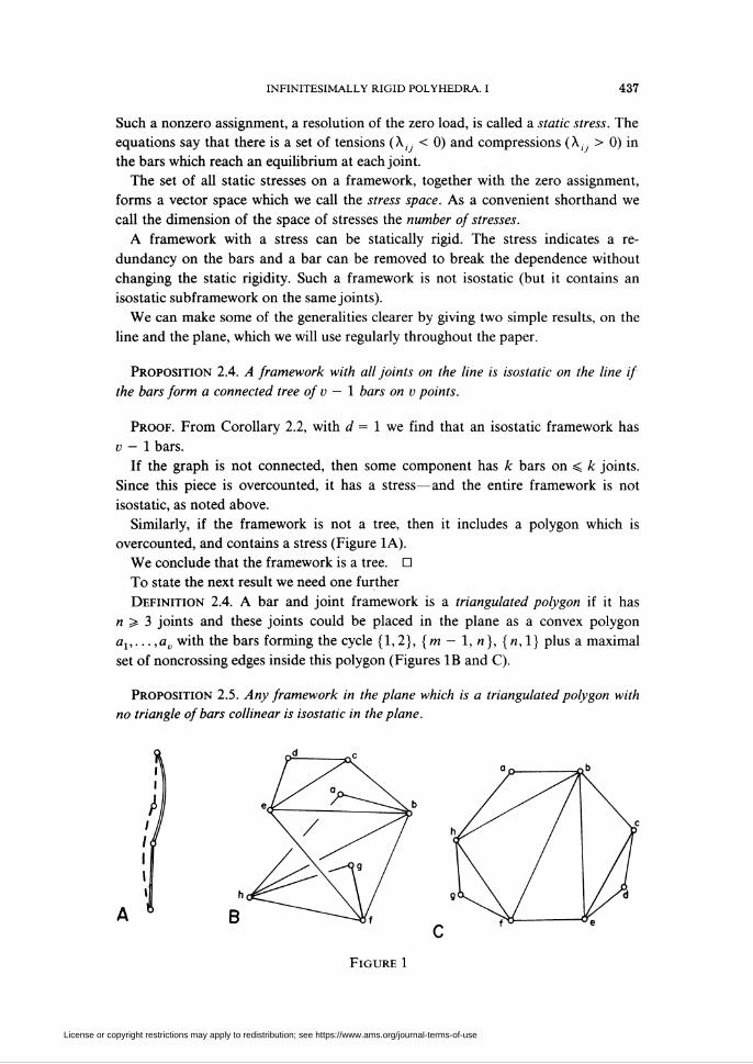
Similarly, if the framework is not a tree, then it includes a polygon which is
overcounted, and contains a stress (Figure 1A).
We conclude that the framework is a tree. D
To state the next result we need one further
Definition 2.4. A bar and joint framework is a triangulated polygon if it has
n > 3 joints and these joints could be placed in the plane as a convex polygon
ax,...,av with the bars forming the cycle {1,2}, {m - 1, «}, {«,1} plus a maximal
set of noncrossing edges inside this polygon (Figures IB and C).
Proposition 2.5. Any framework in the plane which is a triangulated polygon with
no triangle of bars collinear is isostatic in the plane.
Figure 1
License or copyright restrictions may apply to redistribution; see https://www.ams.org/journal-terms-of-use
438 WALTER WHITELEY
Proof. Each triangulation with v > 3 has a 2-valent joint. If we remove this joint
we have a smaller triangulated polygon. When v = 3 such a removal leaves a bar.
We can now reverse this process. Begin with a bar, which is isostatic in the plane. By
Corollary 2.2, repeated addition of 2-valent joints, with the two bars not collinear,
preserves this isostatic property. Since no triangle is collinear, we have the desired
insertions. D
If we think of the bars of an isostatic framework as providing a basis for the space
of equilibrium loads, then there are some simple substitution principles which we
can observe. We will offer two variations—one for spanning sets and one for
independent sets. The case of isostatic frameworks will then follow as a natural
corollary.
Theorem 2.6. //, in a statically rigid framework in d-space, the subframework of all
bars on k joints ax • ■ ■ ak is replaced by a new subframework on these joints which is
statically rigid in the affine subspace spanned by the joints, then the modified framework
is statically rigid in d-space.
Proof. A statically rigid framework gives a spanning set for the equilibrium loads.
We are replacing some elements of this set by a new set which is guaranteed, by its
static rigidity in the subspace, to resolve the loads F¡¡ for bars being deleted. Thus we
have a new spanning set. D
Theorem 2.7. // a framework in d-space is independent (has no stress) and a
subframework among k joints is statically rigid in the affine space spanned by the joints,
and if a modified framework is created by replacing this subframework by a new
independent subframework on these k joints, then the modified framework is indepen-
dent.
Proof. We can extend the original framework to an isostatic framework in
whatever space the joints span. Similarly we can extend the new subframework to be
inserted to a framework isostatic in the space of its joints. The new subframework
will now preserve the static rigidity (Theorem 2.6) and will have the same count of
bars as the isostatic subframework replaced. We conclude that after this replacement
we have an isostatic framework containing the desired modified framework. □
Corollary 2.8. // a framework is isostatic in d-space, with a subframework on k
joints statically rigid in the affine space of its joints, and this subframework is replaced
by another subframework isostatic in the space of these joints, then the modified
framework is isostatic in d-space.
This completes our static preliminaries. We now need an even briefer summary of
the companion theory of infinitesimal kinematics.
Definition 2.5. An instantaneous motion of a bar and joint framework in ¿-space
is an assignment of vectors in ¿-space, (..., o¡,... ), to the joints such that, for each
bar {/, j),
(v¡- ü.)o(a.-a ) = 0.
License or copyright restrictions may apply to redistribution; see https://www.ams.org/journal-terms-of-use
INFINITESIMALLY RIGID POLYHEDRA. I 439
A bar and joint framework is infinitesimally rigid in ¿-space iff every instantaneous
motion can be extended to an assignment of velocities to all points of space such
that (V(p) — V(q))°(p — q) = 0 for each pair of points in space.
The motivation for these definitions lies in the idea of a motion which preserves
the length of all bars: (p - q)°(p - q)= c. If this equation is differentiated we
obtain the given equations on the velocities.
The given conditions on the velocities of an instantaneous motion are a set of
linear equations in the v¡. If we construct the matrix for this system of homogeneous
equations, the rigidity matrix, then the rows of the matrix are the vectors F¡¡ we
employed for the bars. Thus static rigidity was, in essence, a measure of the rank of
the row space of the matrix, while infinitesimal rigidity measures the column rank
(and nullity) of the matrix. It is not surprising that these two concepts of rigidity are
equivalent. We state this result without proof. A general proof appears in [20,
Theorem 4.3]. (To apply that result here, note that tensegrity frameworks include bar
and joint frameworks as a special case (see §5).)
Theorem 2.9. A bar and joint framework is statically rigid in d-space iff it is
infinitesimally rigid in d-space.
The failure of infinitesimal rigidity appears as an internal motion—a set of
velocities which will not extend to a rigid or Euclidean motion of the entire space.
When there are such internal motions, we would like to count "how many". The set
of all infinitesimal motions of a framework forms a vector space, and the motions
extending to rigid motions form a subspace. The difference in dimension between
these two spaces is called the degree of internal freedom of the framework. Equiva-
lently this is the dimension of a quotient space defined by calling two infinitesimal
motions equivalent iff their difference is a rigid motion.
3. Convex polyhedra with triangulated natural faces. The original theorem of
Cauchy, modified by Dehn, can be translated into statics to say that the natural
edges of a convex polyhedron will not hold a static stress [8, 15]. An essential
extension of this theorem, due to Alexandrov, translates to say that, even with
addition of joints along the natural edges, and an arbitrary triangulation of the faces
(including the added joints), the framework will not hold a static stress and thus is
statically rigid as a bar and joint framework [1, 3].
We will begin, in this section, with a proof of a weaker form of Alexandrov's
theorem—with no joints added along the natural edges, but the faces still triangu-
lated. In the next section we will describe general techniques for adding vertices
along the natural edges—techniques which apply to arbitrary statically rigid poly-
hedra.
We need definitions of these basic concepts.
Definition 3.1. An abstract polyhedron is a finite set of vertices vx,...,vn and a set
of faces fx, ...,fm such that
(i) each face is a cycle of distinct vertices/ = (v¿ ,v¡ >, k > 3,
License or copyright restrictions may apply to redistribution; see https://www.ams.org/journal-terms-of-use
440 WALTER WHITELEY
(ii) each edge (an adjacent pair of vertices v¡, v¡ in a face cycle) occurs in exactly
two faces,
(iii) for each vertex v, there is a cycle of faces (/■<»,...,/•<«■>) (m > 3, no
repetitions of faces) such that v, occurs on a common edge between adjacent faces of
the cycle, and Vj occurs on no other edges.
Remark. This is the most general definition we could imagine [24]. Most of this
paper will concentrate on spherical polyhedra (polyhedra where the graph of edges
and vertices can be drawn on a sphere—or the plane with no edges crossing), but a
number of results from §§4-7 will apply more generally.
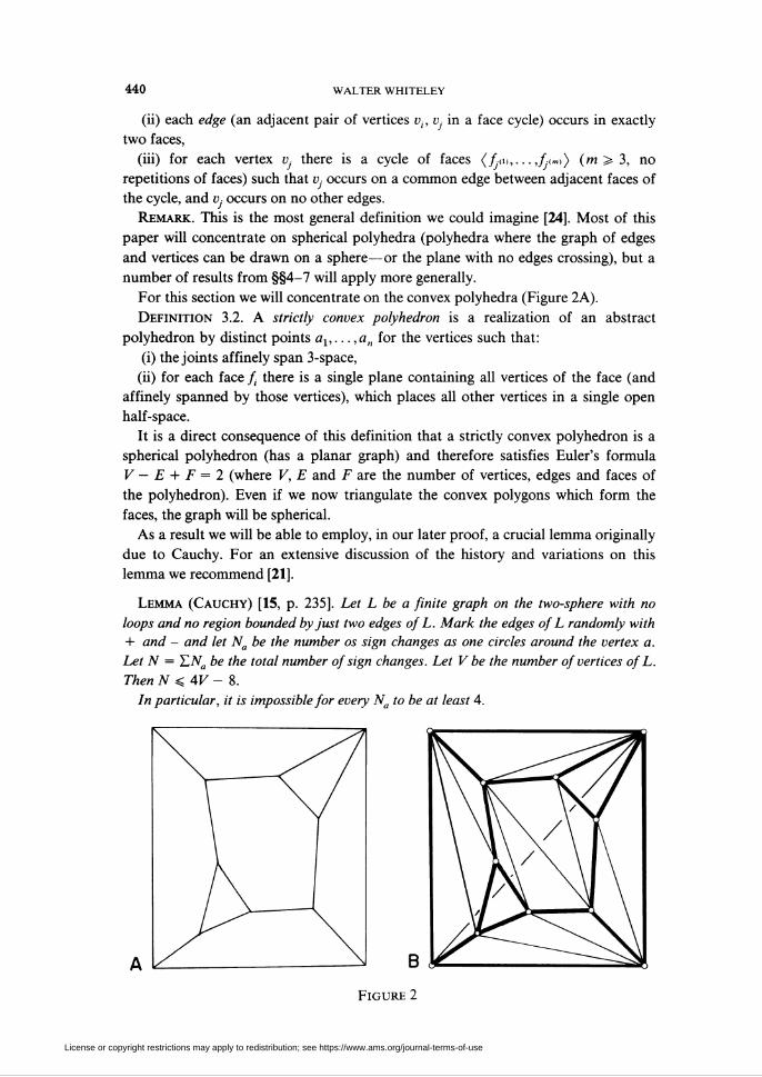
For this section we will concentrate on the convex polyhedra (Figure 2A).
Definition 3.2. A strictly convex polyhedron is a realization of an abstract
polyhedron by distinct points ax,...,an for the vertices such that:
(i) the joints affinely span 3-space,
(ii) for each face f¡ there is a single plane containing all vertices of the face (and
affinely spanned by those vertices), which places all other vertices in a single open
half-space.
It is a direct consequence of this definition that a strictly convex polyhedron is a
spherical polyhedron (has a planar graph) and therefore satisfies Euler's formula
V — E + F = 2 (where V, E and F are the number of vertices, edges and faces of
the polyhedron). Even if we now triangulate the convex polygons which form the
faces, the graph will be spherical.
As a result we will be able to employ, in our later proof, a crucial lemma originally
due to Cauchy. For an extensive discussion of the history and variations on this
lemma we recommend [21].
Lemma (Cauchy) [15, p. 235]. Let L be a finite graph on the two-sphere with no
loops and no region bounded by just two edges of L. Mark the edges of L randomly with
+ and - and let Na be the number os sign changes as one circles around the vertex a.
Let N = T.Na be the total number of sign changes. Let V be the number of vertices of L.
Then N < 4V - 8.
In particular, it is impossible for every Na to be at least 4.
Figure 2
License or copyright restrictions may apply to redistribution; see https://www.ams.org/journal-terms-of-use
INFINITESIMALLY RIGID POLYHEDRA. I 441
We must now define our frameworks (Figure 2B).
Definition 3.3. A strictly convex polyhedral framework is a bar and joint frame-
work formed by
(i) placing a joint at each vertex of a strictly convex polyhedron,
(ii) placing a bar along each edge of the polyhedron,
(iii) triangulating each convex face of the polyhedron and placing a bar along each
edge of this triangulation.
We note that for a triangulated sphere, with V — E + F = 2 and 2E = 3F, we
have E = 3V - 6. Thus such frameworks are statically rigid (and infinitesimally
rigid) iff there is no static stress.
Our proof will center on showing that there is no such stress. While previous
workers have spoken in terms of infinitesimal motions, the pattern we use has a
great deal in common with Cauchy's original proof. This similarity is based on a
general isomorphism which translates infinitesimal motions, given as angular veloci-
ties between adjacent triangles, into scalars for a stress. This specific isomorphism
was presented in [11, §4].
Theorem 3.1. A strictly convex polyhedral framework is statically rigid in 3-space
and is independent.
Proof. The proof will show that there is no static stress on the framework. We
will proceed by induction on the number of joints F in a subframework of any such
strictly convex polyhedral frameworks.
If V < 3, then the subframework is some (or all) of a noncollinear triangle. We
know that there is no stress on such a subframework.
Assume that all such subframeworks with V < Adjoints do not have a static stress.
We now take a subframework H with K + I joints. We further assume that there is a
static stress ( , Xiy, ) on this subframework and proceed to derive a contradiction.
We first drop all bars with A,. = 0. If this isolates any joint, we can drop this
joint, and transfer the stress to a subframework with V < K joints. This would be a
contradiction, so we know that each joint a0 still has a bar (0, j] with X0J =£ 0.
We now want to describe the number of sign changes of the X0J at the joint a0.
Clearly this must be an even number.
Case 1. If the number of sign changes is zero, then all X0J have the same sign
(X0J > 0 for simplicity). By the strict convexity there is a plane at a0 which places all
other vertices into a single open half-space. If N is the normal to this plane we can
assume N °(a0 — a]) > 0 for all bars {0, j} entering a0. Therefore
Wl>o,-(flo - "y)) = EVV°(flo - aj) > °-^ /' J
This contradicts the stress condition that T.jX0J(a0 — ay) = 0, so we conclude that
there must be at least two sign changes.
Case 2. Assume that there are two sign changes. For convenience we list all
remaining edges entering a0 in a cycle, a0ax, a0a2,...,a0am, with X0, > 0 for
1 < i < k and A0 > 0 for k < j < m.
License or copyright restrictions may apply to redistribution; see https://www.ams.org/journal-terms-of-use
442 WALTER WHITELEY
Consider the (unique) plane defined by a0axak, with normal N. By the convexity
of the original polyhedron we have
N°(a0 - a¡) > 0, 1 < /' < k, and N°(a0 - a¿) < 0, k<j^m,
and thus
X0iN°(a0 - a¡) > 0 for all 1 < /' < m.
We conclude that
WlMflo - «,)) = E^o/^°(flo - fl/) > o-i i
Since we started with a stress we conclude that N °(a0 — a¡) = 0 for all 1 < i < m
—and thus all the remaining bars entering a0 are coplanar. Moreover, to obtain an
equilibrium at a0 with no pair of collinear bars, there must be at least three coplanar
bars remaining. This is only possible if N defines a face plane and all remaining bars
he in this face plane.
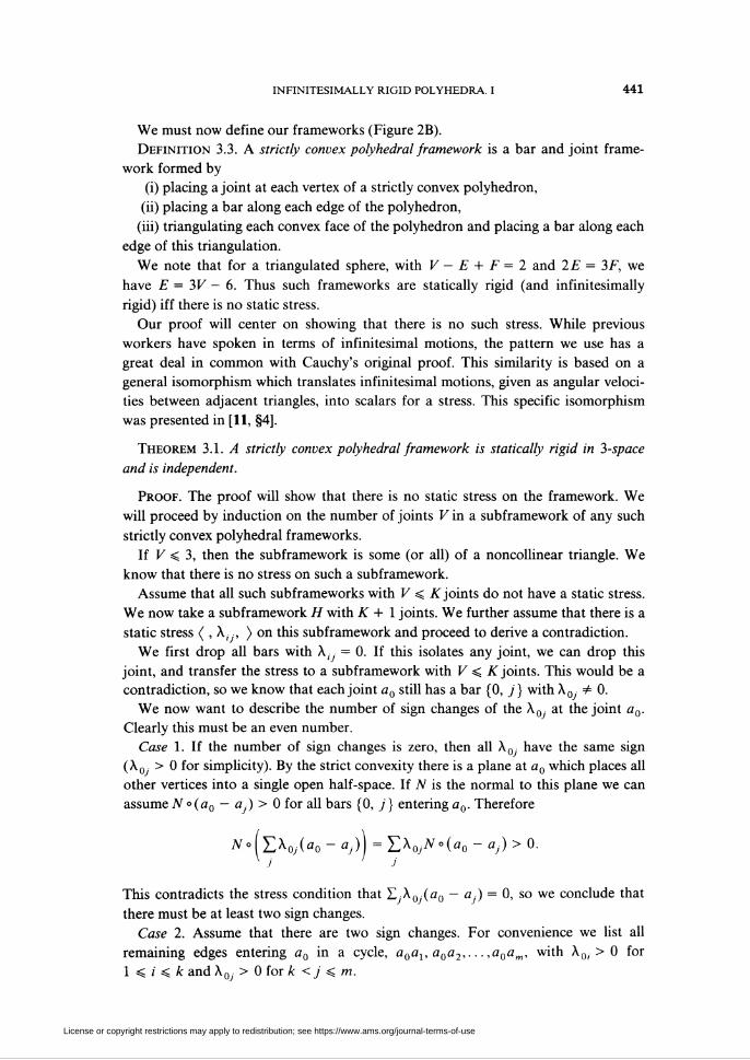
We will now show that this is also impossible by showing how to remove the joint
a0, with all entering bars in a single face, without removing the stress.
Consider the remaining subframework P in this face plane—P contains all the
bars in that plane with X(- • # 0 (Figure 3A). It is a subframework of a triangulated
polygon, so it does not resolve the entire original stress. It must be attached to other
parts of H at joints bx,...,br.
We will define a plane equilibrium load at these joints. Consider the plane
equilibrium load
G = Yi^ij^'j (sum over ('' j) *n ̂ )-
At all vertices except bx,...,bk we have all entering bars of the stress, so G gives a
zero load at these vertices. At each b¡ we have defined G(i), the sum of the forces in
bars of P, and this must exactly match H(i), the sum of the forces in bars at bi not in
P: H(i) + G(i) = 0, with at least some G(i) * 0 (Figure 3B).
We now replace all of P by a new subframework P' on the joints bx,...,br. If
r = 2, we use the bar bxb2 (r # 1 since no single, nonzero force H(i) can be in
Figure 3
License or copyright restrictions may apply to redistribution; see https://www.ams.org/journal-terms-of-use
infinitesimally rigid polyhedra. i 443
equilibrium). If r > 3 we have some vertices of a convex polygon, and we take any
triangulation of this smaller polygon. In both cases, P' is part of some triangulation
of the original face. Since P' is plane-statically rigid, it will resolve the equilibrium
load G with scalars ßu ({i, j) a bar in P').
If we now take H as H - P + P', these scalars /},-. on P' and X,7 on the other bars
will form a non tri vial stress: At b¡ we have
EM*< - °h) + EA,(*i - *,-) = »(0 + G(j) = o.h j
This substitution has transferred the stress to a smaller subframework omitting a0
(Figure 3C)—a situation which contradicts our induction assumption. Thus no joint
a0 can have exactly two sign changes.
Case 3. Every joint of H has at least 4 sign changes in the stress. If we now use the
X,j to assign + and - signs to edges of H we have an assignment contracting Lemma
T.
We conclude that no stress exists on H, and the induction is complete. D
4. Inserting joints on the natural edges. Alexandrov gave an extension of Theorem
3.1 in which vertices are inserted along the interior of the natural edges of the convex
polyhedron, and the faces are triangulated. This result was obtained by an extended
analysis of "sign changes at a vertex" [1]. An English translation of this proof
appears in [3, §6]. Connelly has recently observed that this extension can also be
obtained by a detailed analysis of the infinitesimal motions of a triangulated disc
[10, Remark 6.1].
We will use the static insertions and replacements from §2 to show how to add
vertices on the interior of natural edges of any statically rigid polyhedra. These
techniques make no use of convexity of the polyhedra, convexity of the faces, or any
other details about the polyhedral framework.
In §7 we will give some examples of nonconvex statically rigid polyhedral
frameworks. In §9 we describe, briefly, the current situation on identifying other
classes of statically rigid polyhedral frameworks. It seems helpful to present these
insertions in enough generality to apply to both the current and the anticipated
classes of frameworks.
Definition 4.1. A strict polyhedron in 3-space is a realization of an abstract
polyhedron by distinct points ax,...,an for the vertices such that:
(i) the joints ax,...,an affinely span 3-space,
(ii) for each F¡ there is a single plane containing all vertices of the face (and
affinely spanned by these vertices),
(iii) for each edge, the two faces at this edge have different face planes.
Definition 4.2. A strict polyhedral framework is a bar and joint framework built
by
(i) placing a joint at each vertex of a strict polyhedron,
(ii) placing a bar along each natural edge of the polyhedron,
(iii) placing any desired additional bars between pairs of joints at two vertices of
the same face.
License or copyright restrictions may apply to redistribution; see https://www.ams.org/journal-terms-of-use
444 WALTER WHITELEY
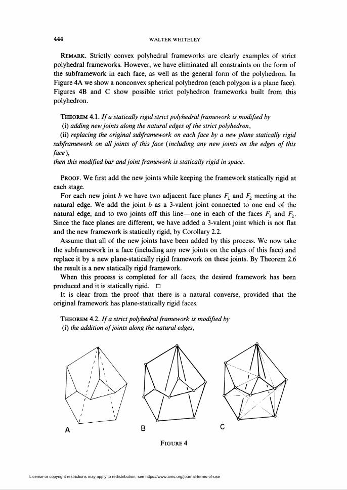
Remark. Strictly convex polyhedral frameworks are clearly examples of strict
polyhedral frameworks. However, we have eliminated all constraints on the form of
the subframework in each face, as well as the general form of the polyhedron. In
Figure 4A we show a nonconvex spherical polyhedron (each polygon is a plane face).
Figures 4B and C show possible strict polyhedron frameworks built from this
polyhedron.
Theorem 4.1. If a statically rigid strict polyhedral framework is modified by
(i) adding new joints along the natural edges of the strict polyhedron,
(ii) replacing the original subframework on each face by a new plane statically rigid
subframework on all joints of this face (including any new joints on the edges of this
face),
then this modified bar and joint framework is statically rigid in space.
Proof. We first add the new joints while keeping the framework statically rigid at
each stage.
For each new joint b we have two adjacent face planes Fx and F2 meeting at the
natural edge. We add the joint b as a 3-valent joint connected to one end of the
natural edge, and to two joints off this line—one in each of the faces Fx and F2.
Since the face planes are different, we have added a 3-valent joint which is not flat
and the new framework is statically rigid, by Corollary 2.2.
Assume that all of the new joints have been added by this process. We now take
the subframework in a face (including any new joints on the edges of this face) and
replace it by a new plane-statically rigid framework on these joints. By Theorem 2.6
the result is a new statically rigid framework.
When this process is completed for all faces, the desired framework has been
produced and it is statically rigid. □
It is clear from the proof that there is a natural converse, provided that the
original framework has plane-statically rigid faces.
Theorem 4.2. If a strict polyhedral framework is modified by
(i) the addition of joints along the natural edges,
Figure 4
License or copyright restrictions may apply to redistribution; see https://www.ams.org/journal-terms-of-use
infinitesimally rigid polyhedra. I 445
(ii) the replacement of the subframework on each face by a new plane subframework,
and this modified framework is statically rigid in space, and if the original framework
had a subframework on each face which was plane-statically rigid,
then the original framework was also statically rigid in space.
Proof. We will simply reverse the steps of the previous proof.
For each added joint on a natural edge we preassign three edges—one along the
natural edge to a natural vertex and one across each adjacent face.
We now replace the final subframework in a face P¡ with the original subframe-
work F¡ of the strict polyhedral framework, plus two bars for each added joint, these
along the two preassigned edges which he in the face plane. Since the original
subframework Ft was plane statically rigid, and the addition of two valent joints
(with the bars not collinear) preserves plane-static rigidity, this entire replacement
preseves the spatial rigidity of the framework.
When this process is completed for all the faces, we have each added joint as a
three-valent joint (the three bars not coplanar). By Corollary 2.3 these can be deleted
to leave a statically rigid framework—the original strict polyhedral framework! D
If we restrict our attention to triangulated spherical polyhedra, this result takes a
simple form. We recall that for such a polyhedron E = 3V - 6, so static rigidity is
equivalent to independence of the bars. Secondly, any triangulation of a polygon
with no collinear triangles is independent and plane-statically rigid. We assume that
any triangulation has no triangle collinear.
Corollary 4.3. Given a strict polyhedral framework which is built on a spherical
polyhedron with each face triangulated by bars, anda modified framework formed by
(i) the addition of joints along the natural edges,
(ii) the replacement of the subframework on each face by a triangulation of the face
polygon with the added joints,
then the modified framework is independent (and statically rigid) iff the original strict
polyhedral framework was independent (and statically rigid).
Proof. The proof proceeds from Theorems 4.1 and 4.2. We need only add the
observations that all facial frameworks are isostatic in the plane, and that, for the
triangulations of a sphere independent is equivalent to static rigidity. D
We note that the "strong form" of Alexandrov's theorem is a particular case of
Corollary 4.3, where the original strict polyhedral framework was convex, and
therefore statically rigid.
Corollary 4.4. // a strictly convex polyhedra is built as a bar and joint framework
by(i) the placement of joints at the natural vertices and along the natural edges,
(ii) the placement of bars on the natural faces to form the polygon on the joints
around the natural edges,
(iii) the placement of bars on the natural faces to follow a triangulation of the new
face polygon,
then the bar and joint framework is statically rigid (and independent) in space.
License or copyright restrictions may apply to redistribution; see https://www.ams.org/journal-terms-of-use
446 WALTER WHITELEY
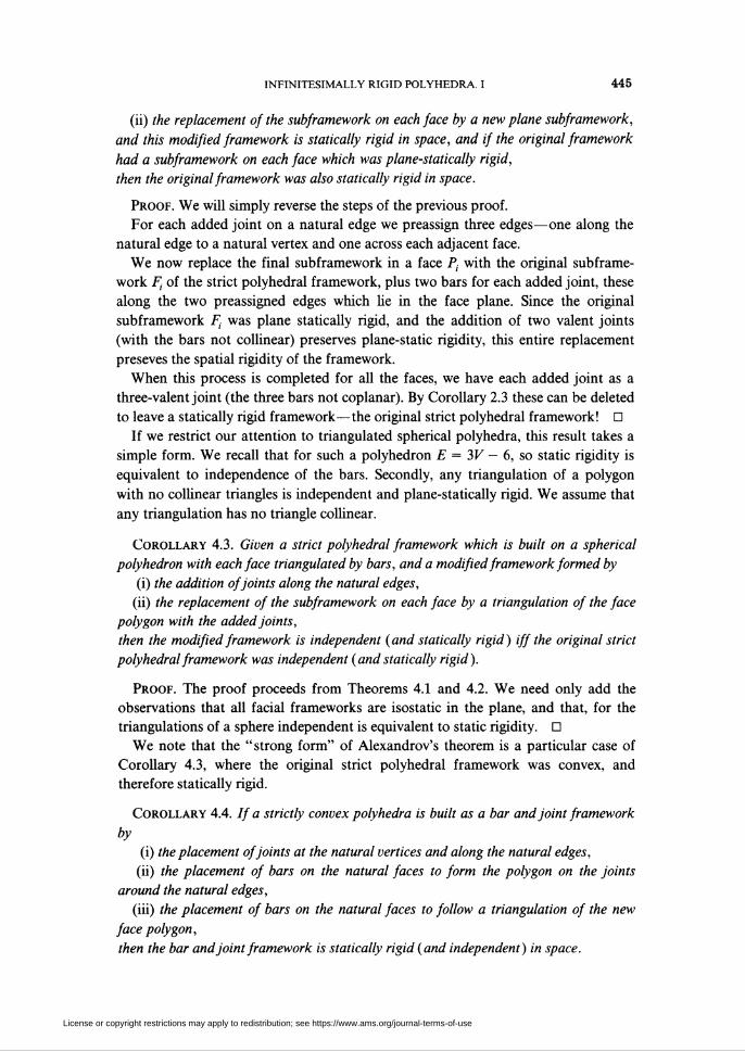
We want to generalize Corollary 4.3 to eliminate the condition that all face
frameworks are triangulations. However, we cannot simply use arbitrary plane-
isostatic frameworks in the faces and expect to obtain an isostatic framework. Figure
5 illustrates the problem (which does not depend on any joints interior to edges). In
Figure 5A we show a nice isostatic (convex) strict polyhedral framework. In Figure
5B, each new face is still plane-isostatic, but the overall framework is statically rigid
and overbraced (E = 3V - 5). There is a stress, which we illustrate in Figure 5C
(using dashed lines for tension, X < 0, and double lines for compression, X > 0). If
we remove one bar (Figure 5D), the new framework is isostatic in space, but one
face has an underbraced subframework.
The key problem is the missing natural edge. Corollary 4.3 has nice generaliza-
tions provided the natural edges are "present"—the subframework on the natural
edge is isostatic in the line (i.e. forms a tree).
Corollary 4.5. Given a statically rigid strict polyhedral framework built on a
spherical polyhedron and a modified framework formed by the addition of joints along
the natural edges, and the replacement of the subframework in each face by a
subframework on all the joints of the face, such that each natural edge has a
subframework isostatic on the line, then
(i) the modified framework is independent iff the subframework in each face of the
modified framework is independent,
(ii) the modified framework is statically rigid iff the subframework in each face of the
modified framework is plane-statically rigid.
Proof, (i) Clearly if the modified framework is independent, then the subframe-
work on each face must be independent.
Conversely, assume that the subframework on each face is independent. We can
add bars to each face to make this subframework plane-statically rigid and indepen-
dent. When this is finished each face F¡ has E(i) = 2V,iX - 3 bars and on each natural
edge (/, j) we have E(ij) = V(ij) — I bars. Since these counts exactly match the
counts for a triangulated sphere, we have E = 3V - 6. Since each face is statically
rigid this extension of the modified framework is statically rigid. We conclude that
this extension is independent and therefore the modified framework was indepen-
dent.
A B C DFigure 5
License or copyright restrictions may apply to redistribution; see https://www.ams.org/journal-terms-of-use
infinitesimally rigid polyhedra. i 447
(ii) Clearly, if each face is plane-statically rigid then, by Theorem 4.1, the entire
modified framework is statically rigid.
Conversely, assume that the entire modified framework is statically rigid, and that
the subframework on each natural edge is a tree on the joints. For the subframework
on each face the bars along the natural edges form an independent set, and we can
delete just enough bars from the interior of the face to make the subframework
independent. Since each deletion removes a stress from the face (and thus from the
entire structure) this leaves a statically rigid framework E > 3V - 6. For each face F¡
we have £(l) < 2K;) - 3 (with a nonnnegative deficit K(i)) and for each natural edge
we have E,¡¡x = F(, y) - 1. By a simple comparison with a triangulation of the same
sphere (using the facial polygons) we have
E + Y,K(i) = 3K-6.
Since we also have E > 3V - 6 we conclude that each K(i) = 0 and the faces are
all still statically rigid. D
The assumption that each natural edge forms a tree is essential as the following
result illustrates.
Corollary 4.6. Given a statically rigid strict polyhedral framework on a spherical
polyhedron, and an independent modified framework formed by the addition of joints
along the natural edges and the replacement of the subframework in each face by an
independent, plane-statically rigid framework on all the joints of the face, then the
subframework on each natural edge is a tree.
Proof. The proof is a simple counting argument, based on a comparison with a
triangulation of the sphere. We will omit it. D
5. Tensegrity frameworks. To this point all of our frameworks have used bars to
join pairs of joints. However, there has been an interest in frameworks using cables
—members which prevent any increase in the distance between the joints, but place
no restriction on a shortening of the distance [10, 14].
It is a simple matter to reconstruct our theory of static rigidity to incorporate the
cables, members which only support tension (X, < 0), and also to incorporate struts,
members which only support compression (XtJ > 0), as well as the bars which permit
a general X,- •. This general static theory for tensegrity frameworks (as well as the
equivalent theory of infinitesimal motions) has been presented in [20].
We will simply summarize the essential definitions and properties here, and then
give the applications to statically rigid polyhedral frameworks.
Definition. 5.1. A tensegrity framework in ¿-space is a set of joints (ax,...,av)
(points in ¿-space) and three pairwise, disjoint collections of unordered pairs {i, j}
of indices for joints B (the bars), C (the cables) and S (the struts) such that for
{/', j} cz E = B U C U S, ai # ay.
An equilibrium load on a tensegrity framework in ¿-space is an assignment of
forces to the joints F = (Fx,... ,FV), F¡ cz Rd, such that the forces are in equilibrium
in space.
A resolution of an equilibrium load by a tensegrity framework is an assignment of
scalars X,y for each {i, j) cz E such that X,y < 0 for {i, j) cz C, and such that
License or copyright restrictions may apply to redistribution; see https://www.ams.org/journal-terms-of-use
448 WALTER WHITELEY
X/7 > 0 for {/', j} cz S, and for each joint ai
EX,y(a, - a-) + F¡ = 0 (sum over 7 with {/', j) cz E).
A tensegrity framework is statically rigid in ¿-space iff the framework has a
resolution for each equilibrium load in ¿-space on the framework.
It is clear that a bar and joint framework is a particular case of a tensegrity
framework, with C = S = 0. In this case all definitions coincide with our previous
definitions.
Without pursuing detailed definitions, we note that infinitesimal rigidity and static
rigidity are equivalent for tensegrity frameworks [20, Theorem 4.3].
As a practical measure, we normally determine the static rigidity of a tensegrity
framework T by a careful comparison with the bar and joint framework T which has
the same joints, but replaces all cables and struts by additional bars.
Theorem 5.1 [20, Theorem 5.2]. A tensegrity framework T is statically rigid in
d-space iff the bar and joint framework T on the same graph is statically rigid in
d-space and the bar and joint framework has a proper stress: a stress (..., X, , ...)
with X,j > 0 for each {i, j) cz S andX¡j < 0 for each {i, j) cz C andXtj arbitrary for
U,j}^B.
Remark. It is a direct consequence of this characterization that we can switch
cables and struts without any change in the static rigidity of a framework (just
multiply the proper stress by -1).
If a spatial framework is statically rigid with even one cable or strut, then it must
have a stress and contain edges which form a basis for the equilibrium loads. As a
result it must have at least 3F - 5 members. Thus a statically rigid tensegrity
framework on the surface of a spherical polyhedron, with at least one cable or strut,
must have crossing members!
Since statically rigid tensegrity frameworks resolve the same loads as statically
rigid bar and joint frameworks all of the substitution principles on static rigidity
from §2 apply directly to tensegrity frameworks. As a result, we can simply translate
Theorem 4.1 to this setting.
Theorem 5.2. // a statically rigid strict polyhedral framework (bar and joint) is
modified by
(i) the addition of new joints along the natural edges of the strict polyhedron,
(ii) the replacement of the subframework on each face by a new plane-rigid tensegrity
subframework on all joints on this face,
then the modified tensegrity framework is statically rigid in space.
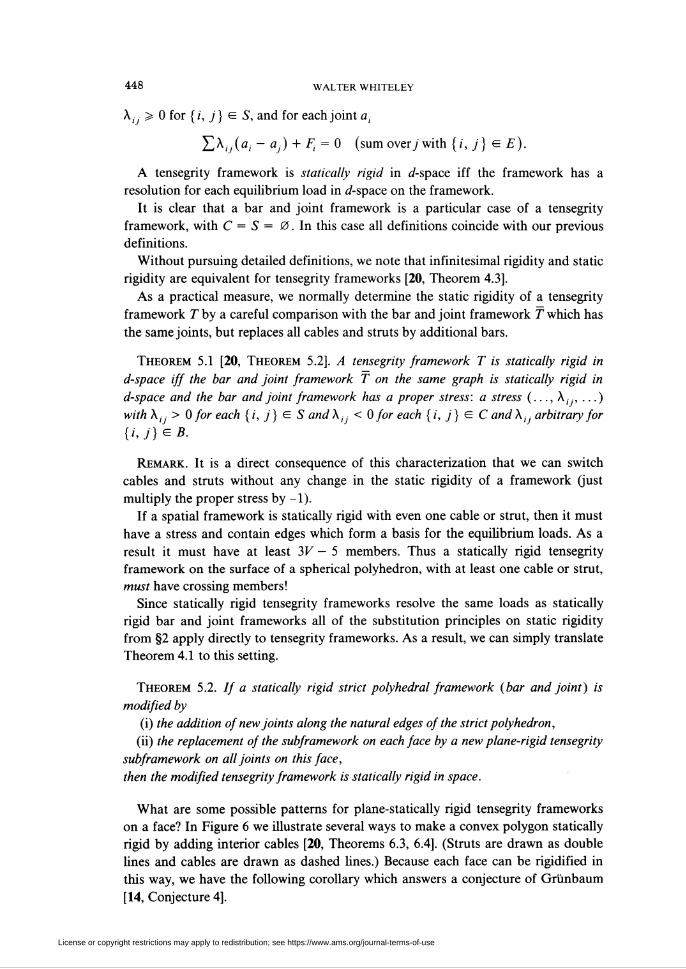
What are some possible patterns for plane-statically rigid tensegrity frameworks
on a face? In Figure 6 we illustrate several ways to make a convex polygon statically
rigid by adding interior cables [20, Theorems 6.3, 6.4]. (Struts are drawn as double
lines and cables are drawn as dashed hnes.) Because each face can be rigidified in
this way, we have the following corollary which answers a conjecture of Grünbaum
[14, Conjecture 4].
License or copyright restrictions may apply to redistribution; see https://www.ams.org/journal-terms-of-use
infinitesimally rigid polyhedra. I 449
Corollary 5.3. If a strict polyhedral framework is statically rigid with all faces
convex, then it is possible to place bars on the natural edges and place sufficient cables
on each face (K — 2 cables for each K-gon K > 3), so that the new tensegrity
framework is statically rigid in space.
For spherical polyhedra, this is the best that we can do. It is a simple observation
that a nonconvex polygon cannot even support a stress with only cables across its
interior (and thus by Theorem 5.1 it will not be plane-statically rigid). Since a sphere
requires that each face be statically rigid we are finished.
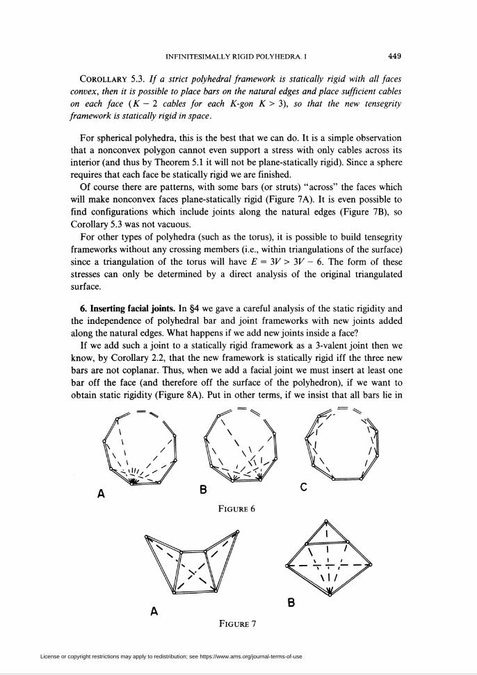
Of course there are patterns, with some bars (or struts) "across" the faces which
will make nonconvex faces plane-statically rigid (Figure 7A). It is even possible to
find configurations which include joints along the natural edges (Figure 7B), so
Corollary 5.3 was not vacuous.
For other types of polyhedra (such as the torus), it is possible to build tensegrity
frameworks without any crossing members (i.e., within triangulations of the surface)
since a triangulation of the torus will have E = 3V > 3V - 6. The form of these
stresses can only be determined by a direct analysis of the original triangulated
surface.
6. Inserting facial joints. In §4 we gave a careful analysis of the static rigidity and
the independence of polyhedral bar and joint frameworks with new joints added
along the natural edges. What happens if we add new joints inside a face?
If we add such a joint to a statically rigid framework as a 3-valent joint then we
know, by Corollary 2.2, that the new framework is statically rigid iff the three new
bars are not coplanar. Thus, when we add a facial joint we must insert at least one
bar off the face (and therefore off the surface of the polyhedron), if we want to
obtain static rigidity (Figure 8A). Put in other terms, if we insist that all bars he in
Figure 6
Figure 7
License or copyright restrictions may apply to redistribution; see https://www.ams.org/journal-terms-of-use
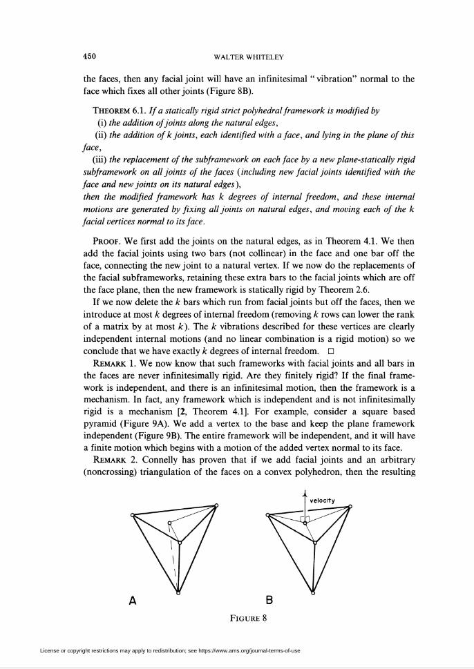
450 WALTER WHITELEY
the faces, then any facial joint will have an infinitesimal " vibration" normal to the
face which fixes all other joints (Figure 8B).
Theorem 6.1. If a statically rigid strict polyhedral framework is modified by
(i) the addition of joints along the natural edges,
(ii) the addition of k joints, each identified with a face, and lying in the plane of this
face,
(iii) the replacement of the subframework on each face by a new plane-statically rigid
subframework on all joints of the faces (including new facial joints identified with the
face and new joints on its natural edges),
then the modified framework has k degrees of internal freedom, and these internal
motions are generated by fixing all joints on natural edges, and moving each of the k
facial vertices normal to its face.
Proof. We first add the joints on the natural edges, as in Theorem 4.1. We then
add the facial joints using two bars (not colhnear) in the face and one bar off the
face, connecting the new joint to a natural vertex. If we now do the replacements of
the facial subframeworks, retaining these extra bars to the facial joints which are off
the face plane, then the new framework is statically rigid by Theorem 2.6.
If we now delete the k bars which run from facial joints but off the faces, then we
introduce at most k degrees of internal freedom (removing k rows can lower the rank
of a matrix by at most k). The k vibrations described for these vertices are clearly
independent internal motions (and no linear combination is a rigid motion) so we
conclude that we have exactly k degrees of internal freedom. □
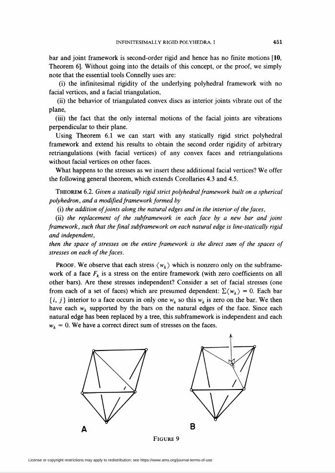
Remark 1. We now know that such frameworks with facial joints and all bars in
the faces are never infinitesimally rigid. Are they finitely rigid? If the final frame-
work is independent, and there is an infinitesimal motion, then the framework is a
mechanism. In fact, any framework which is independent and is not infinitesimally
rigid is a mechanism [2, Theorem 4.1]. For example, consider a square based
pyramid (Figure 9A). We add a vertex to the base and keep the plane framework
independent (Figure 9B). The entire framework will be independent, and it will have
a finite motion which begins with a motion of the added vertex normal to its face.
Remark 2. Connelly has proven that if we add facial joints and an arbitrary
(noncrossing) triangulation of the faces on a convex polyhedron, then the resulting
Figure 8
License or copyright restrictions may apply to redistribution; see https://www.ams.org/journal-terms-of-use
infinitesimally rigid polyhedra. i 451
bar and joint framework is second-order rigid and hence has no finite motions [10,
Theorem 6]. Without going into the details of this concept, or the proof, we simply
note that the essential tools Connelly uses are:
(i) the infinitesimal rigidity of the underlying polyhedral framework with no
facial vertices, and a facial triangulation,
(ii) the behavior of triangulated convex discs as interior joints vibrate out of the
plane,
(iii) the fact that the only internal motions of the facial joints are vibrations
perpendicular to their plane.
Using Theorem 6.1 we can start with any statically rigid strict polyhedral
framework and extend his results to obtain the second order rigidity of arbitrary
retriangulations (with facial vertices) of any convex faces and retriangulations
without facial vertices on other faces.
What happens to the stresses as we insert these additional facial vertices? We offer
the following general theorem, which extends Corollaries 4.3 and 4.5.
Theorem 6.2. Given a statically rigid strict polyhedral framework built on a spherical
polyhedron, and a modified framework formed by
(i) the addition of joints along the natural edges and in the interior of the faces,
(ii) the replacement of the subframework in each face by a new bar and joint
framework, such that the final subframework on each natural edge is line-statically rigid
and independent,
then the space of stresses on the entire framework is the direct sum of the spaces of
stresses on each of the faces.
Proof. We observe that each stress (wk) which is nonzero only on the subframe-
work of a face Fk is a stress on the entire framework (with zero coefficients on all
other bars). Are these stresses independent? Consider a set of facial stresses (one
from each of a set of faces) which are presumed dependent: T.(wk) = 0. Each bar
{i, j} interior to a face occurs in only one wk so this wk is zero on the bar. We then
have each wk supported by the bars on the natural edges of the face. Since each
natural edge has been replaced by a tree, this subframework is independent and each
wk = 0. We have a correct direct sum of stresses on the faces.
Figure 9
¥
License or copyright restrictions may apply to redistribution; see https://www.ams.org/journal-terms-of-use
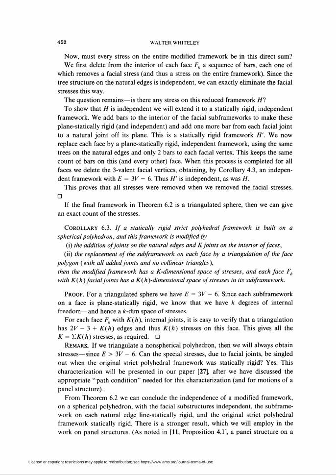
452 WALTER WHITELEY
Now, must every stress on the entire modified framework be in this direct sum?
We first delete from the interior of each face Fk a sequence of bars, each one of
which removes a facial stress (and thus a stress on the entire framework). Since the
tree structure on the natural edges is independent, we can exactly eliminate the facial
stresses this way.
The question remains—is there any stress on this reduced framework HI
To show that H is independent we will extend it to a statically rigid, independent
framework. We add bars to the interior of the facial subframeworks to make these
plane-statically rigid (and independent) and add one more bar from each facial joint
to a natural joint off its plane. This is a statically rigid framework H'. We now
replace each face by a plane-statically rigid, independent framework, using the same
trees on the natural edges and only 2 bars to each facial vertex. This keeps the same
count of bars on this (and every other) face. When this process is completed for all
faces we delete the 3-valent facial vertices, obtaining, by Corollary 4.3, an indepen-
dent framework with E = 3V - 6. Thus H' is independent, as was H.
This proves that all stresses were removed when we removed the facial stresses.
D
If the final framework in Theorem 6.2 is a triangulated sphere, then we can give
an exact count of the stresses.
Corollary 6.3. // a statically rigid strict polyhedral framework is built on a
spherical polyhedron, and this framework is modified by
(i) the addition of joints on the natural edges and Kjoints on the interior of faces,
(ii) the replacement of the subframework on each face by a triangulation of the face
polygon (with all added joints and no collinear triangles),
then the modified framework has a K-dimensional space of stresses, and each face Fh
with K(h) facial joints has a K(h)-dimensional space of stresses in its subframework.
Proof. For a triangulated sphere we have E = 3V - 6. Since each subframework
on a face is plane-statically rigid, we know that we have k degrees of internal
freedom—and hence a /c-dim space of stresses.
For each face Fh with K(h), internal joints, it is easy to verify that a triangulation
has 2V — 3 + K(h) edges and thus K(h) stresses on this face. This gives all the
K = Y,K(h) stresses, as required. D
Remark. If we triangulate a nonspherical polyhedron, then we will always obtain
stresses—since E > 3V - 6. Can the special stresses, due to facial joints, be singled
out when the original strict polyhedral framework was statically rigid? Yes. This
characterization will be presented in our paper [27], after we have discussed the
appropriate " path condition" needed for this characterization (and for motions of a
panel structure).
From Theorem 6.2 we can conclude the independence of a modified framework,
on a spherical polyhedron, with the facial substructures independent, the subframe-
work on each natural edge line-statically rigid, and the original strict polyhedral
framework statically rigid. There is a stronger result, which we will employ in the
work on panel structures. (As noted in [11, Proposition 4.1], a panel structure on a
License or copyright restrictions may apply to redistribution; see https://www.ams.org/journal-terms-of-use
INFINITESIMALLY rigid polyhedra. I 453
polyhedron is infinitesimally rigid if the skeleton of its hinges is independent as a
bar and joint framework.) Since the proof of this result on independence follows the
same pattern as other theorems here, we present the result now.
Theorem 6.4. If an independent strict polyhedral framework is modified by
(i) the addition of joints along the natural edges with a bar across each adjacent face
and the joint splitting the natural edge,
(ii) the addition of joints inside any face of the strict polyhedron, each with two
noncollinear bars in the face, to previously present joints,
(iii) the replacement of the subframework on any plane-statically rigid faces (or a
plane-statically rigid section of the face) by an independent subframework including a
line-statically rigid subframework on each natural edge,
then the modified framework is independent.
Proof. We begin by adding bars (anywhere) to make the original framework
statically rigid and independent.
We now add the new joints, in the fashion of Theorem 6.1 creating a statically
rigid, independent framework. The final replacement of faces which began as
plane-statically rigid, will preserve static rigidity and preserve the count of bars.
Therefore we have created a statically rigid, independent framework containing the
modified framework. D
Remark. The most interesting examples of frameworks which we hope to find
independent are subframeworks of a triangulation of the polyhedron. In this case the
subframework in each face has a planar graph, and we have a geometric characteri-
zation of the independent facial subframeworks: A plane framework with a planar
graph is independent iff the edges do not contain the central projection of a strict
polyhedron from 3-space [23, Corollary 3.5]. This same result, originally observed by
Maxwell [16], can be used to explain the patterns of stress used to produce the
plane-statically rigid tensegrity frameworks described in §5 [23, §4].
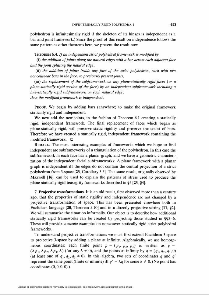
7. Projective transformations. It is an old result, first observed more than a century
ago, that the properties of static rigidity and independence are not changed by a
projective transformation of space. This has been presented elsewhere both in
Euclidean language [20, Theorem 5.10] and in a directly projective setting [11, §2].
We will summarize the situation informally. Our object is to describe how additional
statically rigid frameworks can be created by projecting those studied in §§3-6.
These will provide concrete examples on nonconvex statically rigid strict polyhedral
frameworks.
To understand projective transformations we must first extend Euclidean 3-space
to projective 3-space by adding a plane at infinity. Algebraically, we use homoge-
neous coordinates: each finite point p = (pv p2, p3) is written as p =
(Xpx, Xp2, Xp3, X) (for any X + 0), and the points at infinity by q = (qx, q2, q3,0)
(at least one of qx,q2,q3 + 0). In this algebra, two sets of coordinates q and q'
represent the same point (finite or infinite) iff q' = Xq for some X ¥= 0. (No point has
coordinates (0,0,0,0).)
License or copyright restrictions may apply to redistribution; see https://www.ams.org/journal-terms-of-use
454 WALTER WHITELEY
In these homogeneous coordinates three points p, q and r are collinear iff their
coordinates are linearly dependent. This condition defines lines for points at infinity
as well.
A nonsingular projective transformation, or a collineation, is a transformation
which takes points to points, so that lines map to lines, and 4 noncopolanar points
map to 4 noncoplanar points. In algebraic terms each collineation comes from a
nonsingular linear transformation on the coordinates (from R4 to R4).
If we apply a projective transformation to the joints of a framework, and all the
images of the joints are new finite points, then it is a simple matter to reconstruct the
projected framework by taking Euclidean names for the images of the joints and
taking the same bars {/, j). These bars will, of course, be visuahzed as the line
segments which are now finite.
It is less obvious, but true, that this transformation can be extended to carry static
stresses to static stresses, and thus to preserve static rigidity. The following theorem
summarizes this projective invariance [20, Theorem 5.10].
Theorem 7.1. A bar and joint framework is statically rigid (respectively independent,
stressed) iff a projective transformation of the framework is statically rigid (respectively
independent, stressed).
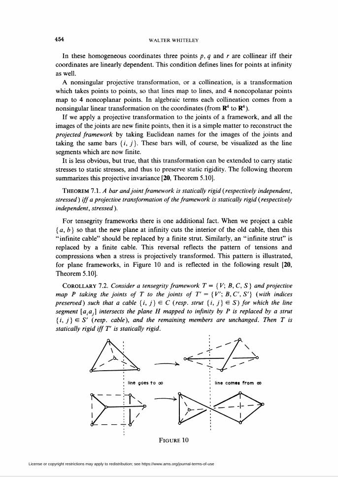
For tensegrity frameworks there is one additional fact. When we project a cable
{a, b) so that the new plane at infinity cuts the interior of the old cable, then this
" infinite cable" should be replaced by a finite strut. Similarly, an " infinite strut" is
replaced by a finite cable. This reversal reflects the pattern of tensions and
compressions when a stress is projectively transformed. This pattern is illustrated,
for plane frameworks, in Figure 10 and is reflected in the following result [20,
Theorem 5.10].
Corollary 7.2. Consider a tensegrity framework T = {V; B, C, S) and projective
map P taking the joints of T to the joints of 7" = {V; B,C, S'} (with indices
preserved) such that a cable {i, j) cz C (resp. strut [i, j} cz S) for which the line
segment [a¡aß intersects the plane H mapped to infinity by P is replaced by a strut
[i, /} £ S' (resp. cable), and the remaining members are unchanged. Then T is
statically rigid iff T is statically rigid.
l-llr
line goes to oo
T \
Figure 10
License or copyright restrictions may apply to redistribution; see https://www.ams.org/journal-terms-of-use
INFINITESIMALLY RIGID POLYHEDRA. I 455
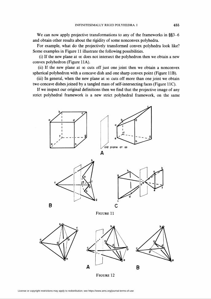
We can now apply projective transformations to any of the frameworks in §§3-6
and obtain other results about the rigidity of some nonconvex polyhedra.
For example, what do the projectively transformed convex polyhedra look like?
Some examples in Figure 11 illustrate the following possibilities.
(i) If the new plane at oo does not intersect the polyhedron then we obtain a new
convex polyhedron (Figure 11A).
(ii) If the new plane at oo cuts off just one joint then we obtain a nonconvex
spherical polyhedron with a concave dish and one sharp convex point (Figure 11B).
(iii) In general, when the new plane at oo cuts off more than one joint we obtain
two concave dishes joined by a tangled mass of self-intersecting faces (Figure 11C).
If we inspect our original definitions then we find that the projective image of any
strict polyhedral framework is a new strict polyhedral framework, on the same
old plane at oo
B
Figure 11
B
Figure 12
License or copyright restrictions may apply to redistribution; see https://www.ams.org/journal-terms-of-use
456 WALTER WHITELEY
abstract polyhedron. We can apply (or reapply) the modifications discussed in
§§4-6 to these polyhedra—adding new joints along the "new natural edges" and in
the "new natural faces". All the theorems generalize to give appropriate static-rigid-
ity, independence, etc.
If an edge or face was cut by the new plane at infinity, the whole sense of
"interior" has changed but the line and plane are not changed. Thus joints added
"along" a natural edge now he "outside" the polyhedron, creating strange flanges
(Figure 12A). However, a careful examination of all the proofs in §§4-6 support the
observation that we never really used "inside" or "outside"—just the lines and
planes, and a clear identification of added joints with edges or faces of the original
polyhedron. Thus it is not important whether we add these new joints before or after
projection—and we are certainly free to rework the faces after projection, whether
they are convex or concave (Figure 12B).
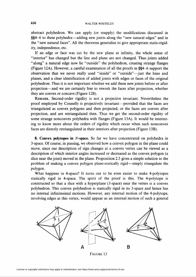
Remark. Second-order rigidity is not a projective invariant. Nevertheless the
proof employed by Connelly is projectively invariant—provided that the faces are
triangulated as convex polygons and then projected, or the faces are convex after
projection, and are retriangulated then. Thus we get the second-order rigidity of
some strange nonconvex polyhedra with flanges (Figure 13A). It would be interest-
ing to know more about the orders of rigidity which occur when such nonconvex
faces are directly retriangulated in their interiors after projection (Figure 13B).
8. Convex polytopes in N-space. So far we have concentrated on polyhedra in
3-space. Of course, in passing, we observed how a convex polygon in the plane could
move, since our description of sign changes at a convex vertex can be viewed as a
description of which interior angles increased or decreased as the convex polygon (a
slice near the joint) moved in the plane. Proposition 2.5 gives a simple solution to the
problem of making a convex polygon plane-statically rigid—simply triangulate the
polygon.
What happens in 4-space? It turns out to be even easier to make 4-polytopes
statically rigid in 4-space. The spirit of the proof is this. The 4-polytope is
constructed so that a slice with a hyperplane (3-space) near the vertex is a convex
polyhedron. This convex polyhedron is statically rigid in its 3-space and hence has
no internal infinitesimal motions. However, any internal motion of the 4-polytope,
involving edges at this vertex, would appear as an internal motion of such a general
Figure 13
License or copyright restrictions may apply to redistribution; see https://www.ams.org/journal-terms-of-use
infinitesimally rigid polyhedra. I 457
slice, so we conclude that this vertex, and its adjacent edges, form an infinitesimally
rigid block in 4-space. If this happens at enough vertices (e.g. all vertices of a convex
4-polytope) then we conclude that all of the 4-polytope is infinitesimally rigid.
This general flavour has been observed by others [21, footnote on p. 119].
However we have not located any direct presentation and it is unclear whether the
basic objects are 4-polytopes composed of 4-space rigid cells, or 3-space rigid cells.
Are we seeing an extension of Cauchy's result (which assumed 3-space rigid 2-faces)
or Alexandrov's result (which assumed plane-rigid 2-faces)?
We will present the 4-dimensional analogue (actually analogues) of Alexandrov's
results in some detail. Following our approach on 3-space, we begin with the
generalization of Theorem 3.1, using only natural vertices. We then modify the
frameworks to allow vertices on any natural edges (1-faces), natural planes (2-faces)
or natural cells (3-faces), and to allow natural static replacements. This entire
pattern extends to any higher dimension without any difficulty, and we state,
without proof, such a result. However, we anticipate that the case in 4-space is
sufficient to yield a different (higher?) perspective on the remarkable coincidence of
triangulations and static rigidity which lives in 3-space.
We begin with our definition of an abstract oriented 4-polytope, and of the
corresponding strict realizations.
Definition 8.1. An abstract oriented 4-polytope is a set of vertices V = {ax,...,av}
and a set of oriented spherical polyhedra {PX,...,P„} (the cells) such that:
(i) the vertices of each cell P¡ lie in V,
(ii) each 2-/ace* (a polygonal face of some P¡) appears in exactly two cells, and has
opposite orientation (as a cycle of vertices) in the two cells,
(hi) for each edge a¡a (adjacent vertices in a 2-face) there is a cycle of cells
PK, PK ,...,PKm (m > 3) such that two adjacent cells share a 2-face containing the
edge afij, and all polyhedra containing this edge appear in the cycle,
(iv) for each vertex ai there is a dual, abstract spherical polyhedron formed with
dual vertices { P/\Pj is a cell containing a,} and dual faces—the cycles P- • • • Pj for
all edges a,a, containing a¡.
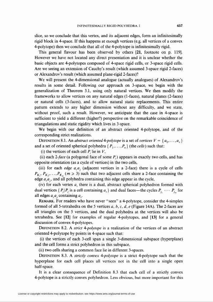
Remark. For readers who have never "seen" a 4-polytope, consider the 4-simplex
formed of all 5-tetrahedra on the 5 vertices a, b, c, d, e (Figure 14A). The 2-faces are
all triangles on the 5 vertices, and the dual polyhedra at the vertices will also be
tetrahedra. See [12] for examples of regular 4-polytopes, and [13] for a general
discussion of convex 4-polytopes.
Definition 8.2. A strict 4-polytope is a realization of the vertices of an abstract
oriented 4-polytope by points in 4-space such that:
(i) the vertices of each 3-cell span a single 3-dimensional subspace (hyperplane)
and the cell forms a strict polyhedron in this subspace,
(ii) two cells sharing a common face lie in different 3-spaces.
Definition 8.3. A strictly convex 4-polytope is a strict 4-polytope such that the
hyperplane for each cell places all vertices not in the cell into a single open
half-space.
It is a clear consequence of Definition 8.3 that each cell of a strictly convex
4-polytope is a strictly convex polyhedron. Less obvious, but more important for this
License or copyright restrictions may apply to redistribution; see https://www.ams.org/journal-terms-of-use
458 WALTER WHITELEY
work, is the fact that if we slice into the 4-polytope near a vertex a0 with a
hyperplane H, which if translated to a0 would miss all the rest of the poly tope, then
the cross-section is a convex 3-polyhedron.
Why? Assume this hyperplane H meets an edge a0a¡ at the point e¡. It therefore
meets a face containing a¡a0aj in an edge e¡, ej, and meets each polyhedral cell
containing a0 in a polygonal face ek,...,ek . Since each 2-face of the 4-polytope was
shared by two cells, each new edge e,e is shared by two of the new faces. Finally
since the hyperplane for Pk placed all other vertices (and edge points e¡) in a single
open half-space, its intersection with H, the face plane of its polygon, place all other
e, into a single half-space of H. This verifies the convexity of the section.
We want to construct our 4-polytopes as bar and joint frameworks. We offer a
general definition, and then a restricted definition for convex 4-polytopes.
Definition 8.4. A strict 4-polytopial bar and joint framework is a bar and joint
framework built on a strict 4-polytope by
(i) placing a joint at each vertex of the poly tope,
(ii) placing a bar on each edge of the 4-polytope,
(iii) placing some additional bars joining pairs of joints which lie on the same cell.
Definition 8.5. A strictly convex 4-polytopial framework is a bar and joint
framework built on a strictly convex 4-polytope by
(i) placing a joint at each vertex of the polytope,
(ii) placing a bar on each edge of the 4-polytope,
(iii) placing, on each 2-face of the polytope, a set of bars which triangulate the
convex plane polygon.
We can give the 4-space analogue of Theorem 3.1.
Theorem 8.1. A strictly convex 4-polytopial framework is infinitesimally rigid in
4-space.
Proof. The proof is based on two observations. If a convex 4-polytopial frame-
work has an internal instantaneous motion (...,»,.,...), then there are 3 adjacent
joints aha0ak such that (vh - vk) • (ah - ak) ¥= 0. Secondly, an appropriate cross-
section of this framework near a0 will also have an internal motion.
We begin by establishing the first principle. Assume that we have an instanta-
neous motion of our framework (..., vt, ...). Further, assume that for each set of 3
adjacent joints ah, a0, ak we have the condition (vh - vk) ■ (ah - ak) = 0. We will
prove that this instantaneous motion extends to a rigid motion of all space.
Take a joint a0. Its 2-link consists of all bars {0, /'} and joints a, attached to this
joint. Since every pair a¡aj lies on a set of 3 adjacent joints, we have, for all pairs,
(vi - Vj) ■ (a¡ - üj) = 0. In addition, the joints a¡ span 4-space (in an affine sense)
so these velocities on the link extend to a rigid motion of 4-space R0. If we go out a
natural edge to an adjacent joint ax, then we find that its 2-link is undergoing the
rigid motion Rx. However, for each 2-face of the polytope containing the edge a0ax
there is a triangle of bars a0axaj and these a. belong to both links. We conclude that
R0 and Rx must agree on all ay, and a0, ax, a set of points spanning 4-space. Thus
License or copyright restrictions may apply to redistribution; see https://www.ams.org/journal-terms-of-use
infinitesimally rigid polyhedra. I 459
R0 = Rx. If we move on down a path of natural edges to any other joint we will find
that all links, and therefore all joints are undergoing the rigid motion R0, as
required.
We now assume that the 4-polytope has an instantaneous motion with 3 adjacent
joints ahaQak satisfying (vh - vk) ■ (ah - ak) # 0. We take a shce near a0 with a
hyperplane H, creating the point e, for each bar a0a¡. Clearly in 4-space these e¡ have
velocities w, from the bars, and
(«, - Uj) • (e,. - ej) = 0 iff (v, - Oj) ■ (e, - e,) = 0.
We now transfer these w, into the 3-space H. Take a unit normal N (in 4-space) for
this hyperplane, and define w¡ = u¡ - (u¡ ■ N)N. The w¡ are the projections, of u¡
into H, down the normal and, since ek, ej are in H we have
(w, - wj) -(e, - ej) = («,- - Uj +(u, ■ N)N-(Uj ■ N)n) -(e, - e,)
= («,. - Uj)-(et- ej).
Now examine the cross-section as a convex polyhedron. For each face of this
polyhedron we had a convex polyhedral framework in the 4-polytope. By Theorem
3.1 this framework is statically—hence infinitesimally—rigid in its 3-space, so for e¡,
e coming from this framework (w, - Uj) • (ei — e¡) = 0. We conclude that, even
after projection, (w¡ - Wj) ■ (e¡ — e-) = 0 for each pair of joints on a face and the w¡
form an allowed instantaneous motion for modified strictly convex polyhedral
frameworks on the ei (with some ei on natural edges of the cross-section). However,
we assumed that (vh — vk) ■ (ah — ak) + 0 and therefore (wh — wk) • (eh — ek) # 0
on the section. This contradicts Corollary 4.4.
This completes the proof that all sets of 3 adjacent joints form a rigid triangle and
hence, that the framework is infinitesimally rigid in 4-space. D
Remark 1. From the proof it is clear that we could assume much less than strict
convexity. What we needed was a connected tree to all vertices, such that at all
vertices which are not 1-valent, a slice forms a 3-space statically rigid polyhedron
(e.g. anything satisfying theorems in §§4-7). In addition, we need to know that each
cell has a subframework which is 3-space statically rigid.
For example, if we build a simple strict 4-polytope (exactly 4 cells at each vertex)
with cells which are 3-space statically rigid, then all sections will be noncoplanar
tetrahedra and the entire framework will be 4-space statically rigid. (It is a nice
exercise to understand why the analogous claim for simple polyhedra (polyhedra in
3-space with 3 faces at each joint) is false.)
In the spirit of §§4-6 we can now proceed to add new joints along the edges,
2-faces and even 3-faces (cells) of a statically rigid 4-polytopial framework. We begin
with the addition of joints along natural edges.
Theorem 8.2. If a statically rigid strict polytopial framework is modified by
(i) the addition of new joints along the natural edges of the 4-polytope,
(ii) the replacement of each cell by a new subframework on all the joints of the cell
which is 3-space statically rigid
then the modified framework is statically rigid in 4-space.
License or copyright restrictions may apply to redistribution; see https://www.ams.org/journal-terms-of-use
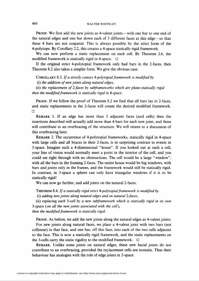
460 WALTER WHITELEY
Proof. We first add the new joints as 4-valent joints—with one bar to one end of
the natural edges and one bar down each of 3 different faces at this edge—so that
these 4 bars are not cospatial. This is always possible by the strict form of the
4-polytope. By Corollary 2.2, this creates a 4-space statically rigid framework.
We can now perform a static replacement on each cell. By Theorem 2.6, the
modified framework is statically rigid in 4-space. D
If the original strict 4-polytopial framework only had bars in the 2-faces, then
Theorem 8.2 also takes a simpler form. We give the obvious case.
Corollary 8.3. If a strictly convex 4-polytopial framework is modified by
(i) the addition of new joints along natural edges,
(ii) the replacement of 2-faces by subframeworks which are plane-statically rigid
then the modified framework is statically rigid in 4-space.
Proof. If we follow the proof of Theorem 8.2 we find that all bars lay in 2-faces,
and static replacements in the 2-faces will create the desired modified framework.
D
Remark 1. If an edge has more than 3 adjacent faces (and cells) then the
insertions described will actually add more than 4 bars for each new joint, and these
will contribute to an overbracing of the structure. We will return to a discussion of
this overbracing later.
Remark 2. The occurrence of 4-polytopial frameworks, statically rigid in 4-space
with large cells and all braces in their 2-faces, is in surprising contrast to events in
3-space. Imagine such a 4-dimensional "house". If you looked out at such a cell,
your line of vision would normally meet a point in the interior of the cell, and you
could see right through with no obstructions. The cell would be a large "window",
with all the bars in the framing 2-faces. The entire house would be big windows, with
bars and joints only in the frames, and the framework would still be statically rigid.
In contrast, in 3-space a sphere can only have triangular windows if it is to be
statically rigid!
We can now go further, and add joints on the natural 2-faces.
Theorem 8.4. If a statically rigid strict 4-polytopial framework is modified by
(i) adding new joints along natural edges and on natural 2-faces,
(ii) replacing each 3-cell by a new subframework which is statically rigid in its own
3-space (on all the new joints associated with the cell),
then the modified framework is statically rigid.
Proof. As before, we add the new joints along the natural edges as 4-valent joints.
For new joints along natural faces, we place a 4-valent joint with two bars (not
collinear) in that face, and one bar, off this face, into each of the two cells adjacent
to the face. This is now a statically rigid framework, and the static replacements on
the 3-cells carry the static rigidity to the modified framework. D
Remark. Unlike some joints on natural edges, these new facial joints do not
contribute to an overbracing, provided the replacement cells are isostatic. Thus their
behaviour has analogies with the role of edge joints in 3-space.
License or copyright restrictions may apply to redistribution; see https://www.ams.org/journal-terms-of-use
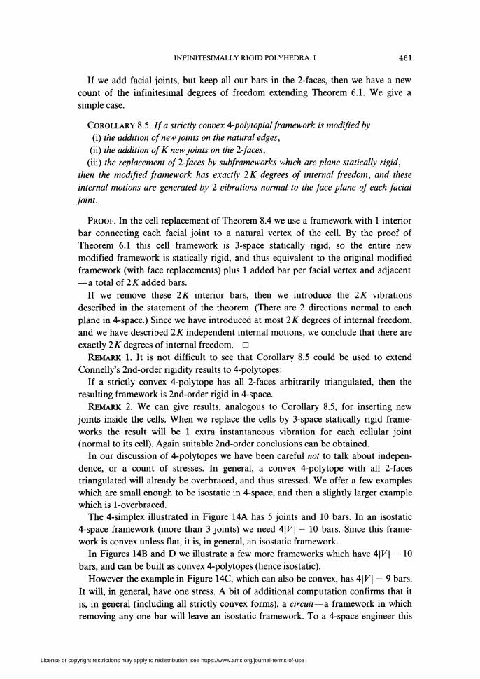
INFINITESIMALLY RIGID POLYHEDRA I 461
If we add facial joints, but keep all our bars in the 2-faces, then we have a new
count of the infinitesimal degrees of freedom extending Theorem 6.1. We give a
simple case.
Corollary 8.5. If a strictly convex 4-polytopial framework is modified by
(i) the addition of new joints on the natural edges,
(ii) the addition of K new joints on the 2-faces,
(iii) the replacement of 2-faces by subframeworks which are plane-statically rigid,
then the modified framework has exactly 2K degrees of internal freedom, and these
internal motions are generated by 2 vibrations normal to the face plane of each facial
joint.
Proof. In the cell replacement of Theorem 8.4 we use a framework with 1 interior
bar connecting each facial joint to a natural vertex of the cell. By the proof of
Theorem 6.1 this cell framework is 3-space statically rigid, so the entire new
modified framework is statically rigid, and thus equivalent to the original modified
framework (with face replacements) plus 1 added bar per facial vertex and adjacent
—a total of 2K added bars.
If we remove these 2K interior bars, then we introduce the 2K vibrations
described in the statement of the theorem. (There are 2 directions normal to each
plane in 4-space.) Since we have introduced at most 2K degrees of internal freedom,
and we have described 2K independent internal motions, we conclude that there are
exactly 2K degrees of internal freedom. D
Remark 1. It is not difficult to see that Corollary 8.5 could be used to extend
Connelly's 2nd-order rigidity results to 4-polytopes:
If a strictly convex 4-polytope has all 2-faces arbitrarily triangulated, then the
resulting framework is 2nd-order rigid in 4-space.
Remark 2. We can give results, analogous to Corollary 8.5, for inserting new
joints inside the cells. When we replace the cells by 3-space statically rigid frame-
works the result will be 1 extra instantaneous vibration for each cellular joint
(normal to its cell). Again suitable 2nd-order conclusions can be obtained.
In our discussion of 4-polytopes we have been careful not to talk about indepen-
dence, or a count of stresses. In general, a convex 4-polytope with all 2-faces
triangulated will already be overbraced, and thus stressed. We offer a few examples
which are small enough to be isostatic in 4-space, and then a slightly larger example
which is 1-overbraced.
The 4-simplex illustrated in Figure 14A has 5 joints and 10 bars. In an isostatic
4-space framework (more than 3 joints) we need 4\V\ - 10 bars. Since this frame-
work is convex unless flat, it is, in general, an isostatic framework.
In Figures 14B and D we illustrate a few more frameworks which have 4\V\ - 10
bars, and can be built as convex 4-polytopes (hence isostatic).
However the example in Figure 14C, which can also be convex, has 4|F| - 9 bars.
It will, in general, have one stress. A bit of additional computation confirms that it
is, in general (including all strictly convex forms), a circuit—a framework in which
removing any one bar will leave an isostatic framework. To a 4-space engineer this
License or copyright restrictions may apply to redistribution; see https://www.ams.org/journal-terms-of-use
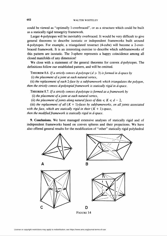
462 WALTER WHITELEY
could be viewed as "optimally 1-overbraced", or as a structure which could be built
as a statically rigid tensegrity framework.
Larger 4-polytopes will be inevitably overbraced. It would be very difficult to give
general theorems to describe isostatic or independent frameworks built around
4-polytopes. For example, a triangulated tesseract (4-cube) will become a 2-over-
braced framework. It is an interesting exercise to describe which subframeworks of
this pattern are isostatic. The 3-sphere represents a happy coincidence among all
closed manifolds of any dimension!
We close with a statement of the general theorems for convex ¿-polytopes. The
definitions follow our established pattern, and will be omitted.
Theorem 8.6. If a strictly convex d-polytope (d > 3) is formed in d-space by
(i) the placement of a joint at each natural vertex,
(ii) the replacement of each 2-face by a subframework which triangulates the polygon,
then the strictly convex d-polytopial framework is statically rigid in d-space.
Theorem 8.7. If a strictly convex d-polytope is formed as a framework by
(i) the placement of a joint at each natural vertex,
(ii) the placement of joints along natural faces of dim < K < d — 2,
(iii) the replacement of all (K + I)-faces by subframeworks, on all joints associated
with the face, which are statically rigid in their (K + I)-space,
then the modified framework is statically rigid in d-space.
9. Conclusions. We have managed extensive analyses of statically rigid and of
independent frameworks based on convex spheres and their projections. We have
also offered general results for the modification of "other" statically rigid polyhedral
Figure 14
License or copyright restrictions may apply to redistribution; see https://www.ams.org/journal-terms-of-use
INFINITESIMALLY RIGID POLYHEDRA. I 463
frameworks. However, we have said very little about what these "other" polyhedral
frameworks might be.
Very little is known about other classes of realizations of, say, a triangulated
sphere, which will always be statically rigid. The general theory runs as follows.
Given an abstract graph (vertices and edges) it can be realized in 3-space as a bar
and joint framework. If it counts to be isostatic (|£| = 3|K| - 6) then the static
rigidity can be measured by the rank of the rigidity matrix [2, Theorem 4.1]. This, in
turn, can be measured by whether certain determinants are zero [15, 22]. (Actually
one determinant is needed, if we are careful [22, §4].) Thus the realizations which are
not statically rigid form an algebraic subspace of R3K, and all of the rest of R3V
consists of realizations which are statically rigid. If there is even one statically rigid
realization, this guarantees that the statically rigid realizations form an open, dense
subset of R3K, and almost all realizations are statically rigid [2, 15].
Our ultimate task is not to refine our techniques for carving out open pieces of R3K
(like the convex realizations of triangulated spheres) which are statically rigid.
Rather the goal should be to describe, or confine that "small" set of geometrically
bad realizations. Since static rigidity is projectively invariant, we should expect the
description to lie within projective geometry [5, 11, 23].
We offer two simple examples of this goal. Consider the octahedral graph (Figure
15A). It is well known that a realization of this graph is statically rigid unless four
alternate face planes concur in a single point (in projective space) (Figure 15B).
Our second example is dual to this—the graph of a cube with the faces triangu-
lated (Figure 15C). We do not know the description for all bad realizations of this
graph, but if the cube is realized so that each of its 6 faces is a plane, then the
framework fails to be statically rigid just when four alternate joints (a, d, b', c') are
coplanar (Figure 15D). In particular, all realizations without self-intersection are
statically rigid. This last observation is a special case of a general pattern: If any
" prism" is realized in 3-space with triangulated plane faces and no self-intersection,
then it is statically rigid [28].
The general problem of characterizing, geometrically, the "bad" realizations, even
of a triangulated sphere, remains an important unsolved problem.
In a companion paper to this, we will investigate the infinitesimal rigidity of panel
polyhedra—polyhedra constructed with infinitesimally rigid panels in place of some,
or all of the faces. This paper will build on the present static results, but the analysis
will be based on infinitesimal motions and on a special correspondence between
motions and stresses presented in [11]. In this context a number of other extensions
to nonconvex polyhedra are available [27].
In closing, we mention two other related areas of research which extend the
methods developed here.
We know, in general, no particular statically rigid realization of a typical triangu-
lation of the torus. However, the techniques of static insertion and static replacement
have been employed to obtain the result that, for each triangulation of the torus,
almost all realizations are statically rigid. We have combined the same techniques
with results from graph theory, to obtain the static rigidity of almost all realizations
License or copyright restrictions may apply to redistribution; see https://www.ams.org/journal-terms-of-use
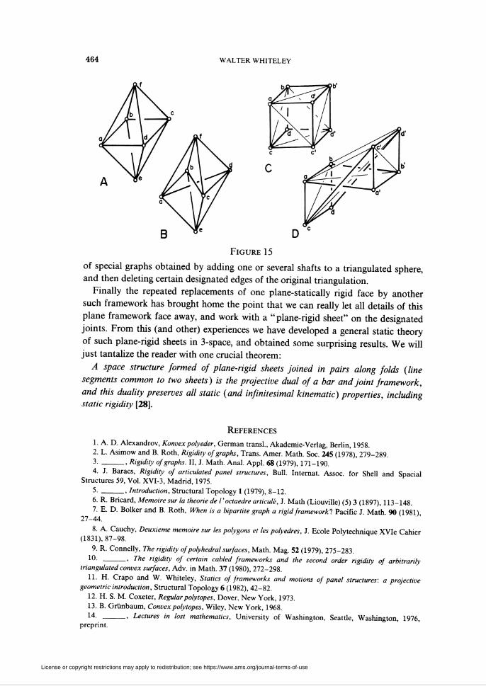
WALTER WHITELEY
Figure 15
of special graphs obtained by adding one or several shafts to a triangulated sphere,
and then deleting certain designated edges of the original triangulation.
Finally the repeated replacements of one plane-statically rigid face by another
such framework has brought home the point that we can really let all details of this
plane framework face away, and work with a "plane-rigid sheet" on the designated
joints. From this (and other) experiences we have developed a general static theory
of such plane-rigid sheets in 3-space, and obtained some surprising results. We will
just tantalize the reader with one crucial theorem:
A space structure formed of plane-rigid sheets joined in pairs along folds (line
segments common to two sheets) is the projective dual of a bar and joint framework,
and this duality preserves all static (and infinitesimal kinematic) properties, including
static rigidity [28].
References
1. A. D. Alexandrov, Konvexpolyeder, German transi, Akademie-Verlag, Berlin, 1958.
2. L. Asimow and B. Roth, Rigidity of graphs, Trans. Amer. Math. Soc. 245 (1978), 279-289.3. _, Rigidity of graphs. II, J. Math. Anal. Appl. 68 (1979), 171-190.
4. J. Baracs, Rigidity of articulated panel structures, Bull. Internat. Assoc. for Shell and Spacial
Structures 59, Vol. XVI-3, Madrid, 1975.
5. _, Introduction, Structural Topology 1 (1979), 8-12.
6. R. Bricard, Mémoire sur la théorie de /'octaèdre articulé, J. Math (Liouville) (5) 3 (1897), 113-148.
7. E. D. Bolker and B. Roth, When is a bipartite graph a rigid framework? Pacifie J. Math. 90 (1981),27-44.
8. A. Cauchy, Deuxième mémoire sur les polygons et les polyèdres, i. Ecole Polytechnique XVIe Cahier
(1831), 87-98.
9. R. Connelly, The rigidity of polyhedral surfaces, Math. Mag. 52 (1979), 275-283.
10. _, The rigidity of certain cabled frameworks and the second order rigidity of arbitrarily
triangulated convex surfaces, Adv. in Math. 37 (1980), 272-298.
11. H. Crapo and W, Whiteley, Statics of frameworks and motions of panel structures: a projective
geometric introduction, Structural Topology 6 (1982), 42-82.
12. H. S. M. Coxeter, Regular poly topes, Dover. New York, 1973.
13. B. Grünbaum, Convex polytopes, Wiley, New York, 1968.
14. _, Lectures in lost mathematics. University of Washington, Seattle, Washington, 1976,preprint.
License or copyright restrictions may apply to redistribution; see https://www.ams.org/journal-terms-of-use
INFINITESIMALLY RIGID POLYHEDRA. I 465
15. H. Gluck, Almost all simply connected closed surfaces are rigid. Geometric Topology, Lectures Notes
in Math., vol. 438, Springer-Verlag, Berlin and New York, 1975, pp. 225-239.
16. L. Henneberg, Die Graphische Statik der Starren Systeme, Liepzig, 1911; Johnson reprint, 1968.
17. N. H. Kuiper, Spheres polyédriques flexible dans E3, d'après Robert Connelly, Sem. Bourbaki 514
(1978), 514-101-514-12.18. J. C. Maxwell, On reciprocal figures and diagrams of forces, Philos. Mag. Ser. (4) 27 (1864), 250-261.
19. B. Roth, Rigid and flexible frameworks. Amer. Math. Monthly 88 (1981), 6-20.
20. B. Roth and W. Whiteley, Rigidity of tensegrity frameorks. Trans. Amer. Math. Soc. 256 (1981),
419-446.
21. J. J. Stoker, Geometric problems concerning polyhedra in the large. Comm. Pure Appl. Math. 21
(1968), 119-168.22. N. White and W. Whiteley, The algebraic geometry of stresses in frameworks, J. Algebraic Discrete
Methods 4 (1983), 481-511.
23. W. Whiteley, Motions, stresses and projected polyhedra. Structural Topology 7 (1983), 13-38.
24._, Readability of polyhedra. Structural Topology 1 (1979), 46-58.
25. _, Introduction to structural geometry. I. Infinitesimal motions and infinitesimal rigidity,
Champlain Reg. Coll., St. Lambert Quebec, preprint 1977.
26. _, Introduction to structural geometry. II. Statics and stresses, Champlain Reg. Coll. St.
Lambert, Quebec, preprint 1978.
27. _, Infinitesimally rigid polyhedra. II. Articulated panels (to appear).
28. _, The static and infinitesimal rigidity of sheet structures (to appear).
Department of Mathematics, Champlain Regional College, St. Lambert, Quebec J4P 3P2,
Canada (Current address)
Topologie Structurale, Ecole d'Architecture, Université de Montréal, Montréal, Quebec
H3C 3J7, Canada
License or copyright restrictions may apply to redistribution; see https://www.ams.org/journal-terms-of-use
![INFINITESIMALLY RIGID POLYHEDRA. II: MODIFIED ......triangulated sphere will flex when one bar is removed. 1. Introduction. In our first paper [25] (hereafter referred to as I), we](https://img.dokumen.tips/doc/110x75/5e6e82c792d8314add56ab2b/infinitesimally-rigid-polyhedra-ii-modified-triangulated-sphere-will-flex.jpg)


![POLYHEDRA - February 2006web.iyte.edu.tr/~gokhankiper/POLYHEDRA - A Historical...polyhedra, but associating them to the elements constructing the world [5] (Fig 7): Fig 7 Johannes](https://img.dokumen.tips/doc/110x75/6137cdd90ad5d2067648dc6d/polyhedra-february-gokhankiperpolyhedra-a-historical-polyhedra-but-associating.jpg)