Embed Size (px)
Citation preview

10th International Conference on Concrete Block Paving Shanghai, Peoples Republic of China, November 24-26, 2012
1
Industry Guidelines for Permeable Interlocking Concrete Pavement in the United States and Canada
David R. Smith, Technical Director
Interlocking Concrete Pavement Institute 13921 Park Center Road, Suite 270, Herndon, Virginia 20171 USA
Tel +01-703-657-6900; Fax: +01-703-657-6901 Email: [email protected] Summary In 2011, the Interlocking Concrete Pavement Institute (ICPI) released the 4th edition of the manual, Permeable Interlocking Concrete Pavements – Design Specifications Construction Maintenance. This paper provides an overview of this 100-page book on permeable interlocking concrete pavements (PICP) which communicates industry best practices in the United States and Canada. This summary provides highlights from the publication’s five chapters; Overview; Design Contexts, Overview and Guidelines; PICP Design; Construction; and Maintenance. Compared to previous editions, the design chapter has expanded formulas for sizing full and partial exfiltration PICP designs using perforated drain pipes. An entirely new section covers structural design for supporting vehicular traffic and includes a base/subbase thickness design chart. The construction chapter covers essentials on residential and commercial projects and includes an updated guide construction specification. The final chapter on maintenance references research and experiential information on types and performance of vacuum sweepers for regular maintenance and remediation of neglected surfaces clogged with sediment. There is a construction and maintenance checklist, plus a model municipal ordinance to encourage PICP use by municipalities on public and private projects. Besides the numerous references, an updated glossary of terms is provided. Key Words: permeable interlocking concrete pavement. permeable pavement design. permeable pavement hydrologic and structural design. permeable pavement construction. permeable pavement maintenance. 1. Chapter 1 - Overview Since 2009, PICP use in the United States has grown 15% to 20% annually due to national, provincial, state and municipal regulations requiring reduction of stormwater runoff and water pollution. Canadian use has expanded primarily due to municipal regulations. PICP is one of several tools or best management practices (BMP) adopted by a growing number of stormwater agencies. Addressing these legal requirements, the first chapter of the manual defines the PICP system as shown in Figure 1. Since its introduction to the North American market in the 1990s, the PICP assembly has evolved into a three layer system consisting of (1) minimum 80 mm thick concrete pavers, jointing and bedding course materials; (2) a 100 mm thick open-graded aggregate base reservoir; and (3) an open-graded aggregate subbase reservoir that varies in thickness depending on traffic and water storage requirements. The subbase aggregate is

10th International Conference on Concrete Block Paving Shanghai, Peoples Republic of China, November 24-26, 2012
2
thicker than the base aggregate and this thicker layer with larger aggregates provide additional structural stability with water storage. The underdrain pipe shown in Figure 1 is perforated and can be used in low infiltration soils to remove water that cannot infiltrate within a given time period, usually 48 to 72 hours. This pipe (or pipes) is typically installed on or near the soil subgrade with a raised outflow drain that removes excess water. Geotextile at the bottom of the subbase (directly over the soil horizontal soil subgrade) is optional. If used there, geotextile should conform to AASHTO M-288 Geotextile Specification for Highway Applications (AASHTO 2010). While geotextiles can provide structural support, the amount of deformation that renders such support is well beyond that tolerated in segmental pavement systems. If placed horizontally on the soil subgrade, geotextile must be selected to reduce its clogging potential from fine soil particles. AASHTO M-288 assists with the selection process. When no full-depth concrete curb or other structure is present to contain the base and subbase, geotextile is recommended along the vertical sides of the excavated soil perimeter to prevent soil intrusion. The soil subgrade is typically uncompacted. Some installations may require soil compaction for additional stability under vehicular traffic. Soil subgrade compaction affects infiltration and this must be considered in the hydrologic design. Figure 1. Schematic view of permeable interlocking concrete pavement Chapter 1 lists the PICP benefits as noted below. Reduced Runoff
• Up to 100% surface runoff reduction • Up to 100% infiltration depending on the design and soil subgrade infiltration rate • Capable of installation over or next to plastic or concrete underground storage vaults
10th International Conference on Concrete Block Paving Shanghai, Peoples Republic of China, November 24-26, 2012
3
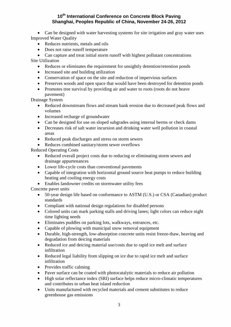
• Can be designed with water harvesting systems for site irrigation and gray water uses Improved Water Quality
• Reduces nutrients, metals and oils • Does not raise runoff temperature • Can capture and treat initial storm runoff with highest pollutant concentrations
Site Utilization • Reduces or eliminates the requirement for unsightly detention/retention ponds • Increased site and building utilization • Conservation of space on the site and reduction of impervious surfaces • Preserves woods and open space that would have been destroyed for detention ponds • Promotes tree survival by providing air and water to roots (roots do not heave
pavement) Drainage System
• Reduced downstream flows and stream bank erosion due to decreased peak flows and volumes
• Increased recharge of groundwater • Can be designed for use on sloped subgrades using internal berms or check dams • Decreases risk of salt water incursion and drinking water well pollution in coastal
areas • Reduced peak discharges and stress on storm sewers • Reduces combined sanitary/storm sewer overflows
Reduced Operating Costs • Reduced overall project costs due to reducing or eliminating storm sewers and
drainage appurtenances • Lower life-cycle costs than conventional pavements • Capable of integration with horizontal ground source heat pumps to reduce building
heating and cooling energy costs • Enables landowner credits on stormwater utility fees
Concrete paver units • 50-year design life based on conformance to ASTM (U.S.) or CSA (Canadian) product
standards • Compliant with national design regulations for disabled persons • Colored units can mark parking stalls and driving lanes; light colors can reduce night
time lighting needs • Eliminates puddles on parking lots, walkways, entrances, etc. • Capable of plowing with municipal snow removal equipment • Durable, high-strength, low-absorption concrete units resist freeze-thaw, heaving and
degradation from deicing materials • Reduced ice and deicing material use/costs due to rapid ice melt and surface
infiltration • Reduced legal liability from slipping on ice due to rapid ice melt and surface
infiltration • Provides traffic calming • Paver surface can be coated with photocatalytic materials to reduce air pollution • High solar reflectance index (SRI) surface helps reduce micro-climatic temperatures
and contributes to urban heat island reduction • Units manufactured with recycled materials and cement substitutes to reduce
greenhouse gas emissions

10th International Conference on Concrete Block Paving Shanghai, Peoples Republic of China, November 24-26, 2012
4
Maintenance & Repairs
• Paving units and base materials can be removed and reinstated • Utility cuts into the pavement do not damage the surface and decrease pavement life • Capable of repairs in below freezing temperatures • No unsightly patches from utility cuts • Surface cleaning with regenerative air vacuum equipment • Clogged surfaces may be restored with higher force, full vacuum equipment to
reinstate infiltration rates 2. Chapter 2 – Design Contexts, Overview and Guidelines Given the range of geography, rainfall patterns, and urban settlement patterns in North America, provinces, states, counties and cities have a range of regulations controlling stormwater runoff. All of them aim to reduce stormwater runoff and/or specific pollutants to receiving waters. Many older cities have combined storm and sanitary sewer systems that release significant volumes of untreated, highly polluted water into nearby lakes and rivers during heavy rainfall. Other cities have storm sewers whose capacity has been exceed due to additional development and runoff. This results in minor flooding of streets, building basements, and damage to drainage systems, riparian environments, roads and structures. PICP can address many of these problems by storing and infiltrating runoff, particularly from storms that have higher than a 10% probability of recurring (i.e., less than a 10-year storm). West of the 105th meridian, rainfall generally decreases to less than 0.5 m annually. In many semi-arid and desert regions such as much of California, Nevada, Arizona, New Mexico, and western Texas, filtering and treatment of stormwater to reduce pollutants and aquifer recharge are priorities rather than reducing runoff volumes. Research literature referenced in the ICPI manual demonstrates the effectiveness of PICP in filtering and treating many stormwater pollutants. In response to increasing development and stormwater runoff, many city and county governments have formed stormwater utilities that charge residential and commercial property owners a fee to remove stormwater from their properties. Generally, a larger impervious area (i.e., pavement and roofs) results in higher fees. Public stormwater utilities are similar in structure to water and sanitary sewer utility companies. Some stormwater utilities offer a reduction in fees if permeable pavements or other methods are used to keep runoff from entering the public storm sewer system. This provides a modest financial incentive for land developers and property owners to use PICP. Chapter 2 provides the basic system options—full, partial or none—for exfiltrating the open-graded aggregate base into the underlying soil subgrade. These approaches have been articulated elsewhere by ICPI in earlier versions of this manual and adopted by other industry association and agency guidelines. The chapter lists places favorable and unfavorable to PICP, specifically where infiltration presents a high risk of soil, groundwater or surface water pollution. PICP has been used on sites up to a 12% surface slope. For many sloped projects, barriers or berms within the base/subbase are used to slow water and encourage infiltration into the soil

10th International Conference on Concrete Block Paving Shanghai, Peoples Republic of China, November 24-26, 2012
5
subgrade. Figure 2 illustrates an example of concrete barriers within a PICP base that hold water running down an municipal alley, then overflowing to the next down slope area. The chapter also covers cold climate design considerations. Research in Chicago, Illinois, demonstrated the ability of the PICP base to not freeze in the winter. The City of Chicago Department of Transportation monitored ambient air and in the upper, middle, and lower portions of a PICP parking lot from September 2008 to February 2009. Temperature data indicated that none of the PICP layers reached freezing temperatures. The coldest day, January 16, 2009, was -21.7° C not including the wind chill factor. The coldest temperatures were as follows: upper area 0.7° C; middle 1.2° C and lower base 3.7° C (Attarian 2010).
Research on other permeable pavements in cold climates using open-graded bases (similar to that in PICP) provide further explanations for an absence of heaving and not needing a frost protection layer. Kevern (Kevern 2009) studied temperatures in open-graded bases under pervious concrete during the winter and concluded that, “Air in the aggregate base…acts as an insulating layer that, coupled with the higher latent heat associated with the higher soil moisture content, delays or eliminates the formation of a frost layer…while maintaining permeability.” He also noted faster thawing than traditional concrete pavement. Houle (Houle 2009) at the University of New Hampshire Stormwater Center
measured air and base temperatures in an installation there of porous asphalt base. His findings agreed with Bäckström (Bäckström 2000) study on porous asphalt bases that yielded greater resistance to freezing, decreased frost penetration and more rapid thawing than conventional pavement due to higher water content in the underlying soil which increased the latent heat in the ground. The conclusions of these studies agree with the finding of Kevern (2009) and Attarian (2010). This heat-holding characteristic of open-graded bases enables permeable surfaces on them to use lower quantities of deicing materials and commensurate cost savings than that required for conventional impervious pavements. Substantial reductions have been observed on porous asphalt (UNHSC 2008) and PICP can expect similar reductions when sunlight exposure and temperatures melts snow and it immediately infiltrates into the surface. Figure 3 illustrates this melting which can also reduce slipping hazards from ice and related legal liability. Unacceptably high concentrations of deicing salts and sand in snowmelt from impervious surfaces into PICP as well as those placed directly on it requires some design considerations. The considerations apply in climates with extended winters having large, rapid volumes of snow melt in the late winter and early spring. Such areas are mostly in the northern U.S. and Canada (Caraco 1997). There is no BMP including PICP that removes chlorides in deicing materials. Studies by Van Seters (2007) on PICP suggest that potential for deicing salts to
Figure 2. Concrete check dams slow water In this PICP alley in Richmond, Virginia.

10th International Conference on Concrete Block Paving Shanghai, Peoples Republic of China, November 24-26, 2012
6
mobilize heavy metals may require increasing the depth of soil to the seasonally high ground water table to 2 m or more below the PICP subbase for filtering purposes. 3. Chapter 3 - Design PICP provides a stormwater management practice and a vehicular traffic bearing surface. The thickness of the permeable pavement and reservoir layer must be sized to support structural loads and temporarily store stormwater. The design storm is often designated by the local stormwater agency and represents a rainfall depth and resulting volume to infiltrate and/or detain inside the PICP and slowly release. The volume can be that required to improve quality, a higher volume to protect downstream channel erosion, or higher still to assist in controlling local flooding. Each of the components in the permeable pavement cross section shown below must be specified to manage this water volume, pass higher volumes through it, while considering site land use, drainage patterns, soil type, and vehicular loads.
The flow chart and decision tree shown in Figure 4 provides paths for structural and hydrologic design analysis. A subbase thickness is determined from structural and hydrologic analyses and the thicker one is selected. Specific design factors for each are discussed below. 3.1 Hydrologic Design Hydrological design generally relies on the following variables:
• Design storm or storms and rainfall depth, typically issued by the local stormwater agency
• Long-term soil infiltration rate, estimated or measured on-site with
an appropriate safety factor added by the designer
• Base/subbase reservoir thickness and storage capacity (typically 30 to 40% of the total volume)
Swan (2009) characterized water entering the pavement surface as a water balance among sources and destinations. Dynamic computational methods use small time steps to estimate the expected water inflow from precipitation and any surrounding areas that drain onto the permeable pavement. Infiltration, subsurface outflow, and possible surface runoff during each time step are also calculated. For computer modeling, all inflow from adjacent areas is assumed to be sheet flow into permeable pavement. The permeable pavement surface has an infinite inlet capacity. Pavement surface infiltration rates should be input by the user based on test results or experience. Rainfall timing can be important when evaluating permeable pavement potential to infiltrate water from surrounding areas. The time delay between the rainfall on these areas (with some infiltration) and the time the water enters the permeable pavement surface during
Figure 3. Snow remaining after plowing PICP can melt and reduce ice formation and slipping hazards.

10th International Conference on Concrete Block Paving Shanghai, Peoples Republic of China, November 24-26, 2012
7
the peak rainfall intensity can also reduce the peak outflow, thereby conserving the need for larger storm sewer pipes and reducing potential downstream erosion. Stormwater exfiltrates from the permeable pavement base into the soil subgrade, groundwater, and/or underdrains. In addition, there is outflow via perforated pipes, plus evaporation/ transpiration which can be a consideration in arid climates. The designer needs to carefully estimate the amount of water infiltrating into the soil subgrade and into underdrains. They are typically used over low infiltration soils and the designer specifies the pipe size, slope, horizontal spacing and outflow height above the soil subgrade. The latter can be important to creating some water detention in the base for infiltration and nutrient reduction through de-nitrification.
Figure 4. Structural and hydrologic analysis decision tree (Smith 2011) Measured or referenced soil subgrade permeability should be a saturated conductivity that yields a design infiltration rate for hydrologic calculations. The simplest approach uses Darcy’s Law (Cedergren 1989). The Green-Ampt equation can be used as well. Since the water table is typically some distance below the base/subbase layer, the hydraulic gradient can be assumed to be 1.0 as the drop in elevation causes downward flow. Most designs assume that water infiltration drainage into the soil subgrade occurs uniformly across the bottom of the pavement as the base/subbase becomes saturated. Since predicting sediment loading on the soil subgrade and reduction of infiltration is difficult, a conservative infiltration reduction factor of 0.5 (safety factor of 2) can be applied

10th International Conference on Concrete Block Paving Shanghai, Peoples Republic of China, November 24-26, 2012
8
to account for potential clogging and reduction of the soil subgrade infiltration rate. As the water depth in the subbase increases, the static pressure increases and this affects the drainage rate. Permeable pavements may be designed to detain water which can assist in nutrient reduction. This approach is more amenable in low-infiltration rate clay soils which can also capture metals. In such cases, detention pond design principles can be applied to inflow, storage and outflow calculations. The maximum resident time for water generally should not exceed 72 hours including the storm duration. Excess water that cannot be contained by the base/subbase exits to swales, to adjacent down slope bioretention areas, or to catch basins and storm sewers. Besides detention that encourages de-nitrification, additional nutrient treatment can be realized by sand filters or release to down slope bioretention areas. Consideration should be given to the size and location of sand filters as they substantially increase costs and will likely not be maintained if they clog. Permeable pavement over expansive soils is not recommended unless an impermeable liner is used under the base/subbase to prevent water from entering the expansive soil subgrade. Another option is stabilizing the expansive soil. This will render the soil practically impervious and this condition must be considered in hydrologic design. PICP pavement can also be designed to address, in whole or in part, the detention storage needed to comply with municipal channel protection and/or flood control requirements. The designer can model various approaches that consider storage within the stone aggregate layer, expected infiltration, and any outlet structures used as part of the design. Routing calculations can also be used to provide a more accurate solution of the peak discharge and required storage volume. 3.2 Structural Design For structural design of impervious (conventional) roads and base, many local, state and provincial agencies use design methods published AASHTO in Guide for Design of Pavement Structures (AASHTO 1993). While the AASHTO methodology is familiar to many civil engineers, stormwater agency personnel are unfamiliar with it and often require an introduction to this design tool. State and provincial highway engineers are moving toward the AASHTO 2004 Mechanistic-Empirical Pavement Design Guide for New and Rehabilitated Pavement Structures (AASHTO 2004) which relies on mechanistic design and modeling, i.e., analysis of loads and resultant stresses and strains on materials and the soil subgrade. The AASHTO 2004 mechanistic design model was developed and calibrated by state, provincial and federal highway agencies across a wide range of highway loads, load testing, soil types and climatic conditions. This model has not been calibrated for permeable pavements subject to significantly less traffic loads and constructed with open-graded, crushed stone bases. Many local transportation agencies use the empirically-based AASHTO 1993 Guide whose underlying concepts emerged from test pavements (many with dense-graded bases) in the 1950s repeatedly trafficked by trucks that established relationships among materials types, loads and serviceability. The AASHTO equation in the 1993 Guide calculates a Structural Number or SN given traffic loads, soil type, climatic and soil moisture conditions.

10th International Conference on Concrete Block Paving Shanghai, Peoples Republic of China, November 24-26, 2012
9
The designer then finds the appropriate combination of pavement surfacing and base materials whose strengths are characterized with layer coefficients. When added together, the coefficients (representing various pavement material thicknesses) should meet or exceed the Structural Number required for a design. This empirical design approach appears to be applicable to permeable pavement with some consideration given to layer coefficients. For design purposes, the assumed AASHTO layer coefficient for the minimum 80 mm thick paver and 50 mm thick aggregate bedding layer is 0.3. This layer coefficient considers wider joints and larger aggregates in PICP paver joints compared to the 0.44 layer coefficient (equivalent to asphalt) for sand-filled paver joints for interlocking concrete pavement as described in ASCE 58-10 Structural Design of Interlocking Concrete Pavement for Municipal Streets and Roadways. The required subbase thicknesses in Table 1 are calculated using the AASHTO methodology which considers design reliability, design life, estimated traffic, and subgrade soil type, This table includes the following design assumptions:
• 80% confidence level • Resilient modulus or Mr in psi = 2,555 x CBR0.64; Mr in MPa = 17.61 x CBR0.64
(CBR = California Bearing Ratio) • Open-graded aggregate base layer coefficient = 0.09 • Open-graded aggregate subbase layer coefficient = 0.06 • Commercial vehicles = 10%; Average ESALs per commercial vehicle = 2 • Total PICP cross section depth equals the sum of the subbase, 100 mm thick base, 50
mm thick bedding and 80 mm thick concrete pavers. For full or partial infiltration designs, it is good practice to have at least 0.6 m of soil between the bottom of the subbase and the elevation of the seasonal high water table for pollutant filtering purposes and soil stability when saturated. For no exfiltration designs, this height can be reduced to 0.3 m under the PICP subbase. A number of full and partial exfiltration PICP projects successfully perform in coastal areas. Many projects are over sandy soils and high water tables with tidal influences in groundwater levels. Sandy soils offer stability when saturated and underdrains can be designed to remove or reduce high groundwater levels within the PICP base/subbase. There is always design consideration given to overflow conditions since permeable pavements are designed to infiltrate and drain water volumes from a specific range of storms. Excess water from high rainfall depth or that from repeated storms is best handled through underdrain pipes at the lowest elevations of the PICP. Overflows from extreme rainfall events are directed to swales, streams, ponds or storm sewers. This drainage method is preferred to allowing excess water to rise out of and drain from surface and potentially mobilizing sediment and pollutants situated in the stone-filled PICP openings. 4. Chapter 4 – Construction PICP construction for vehicular applications follows the steps listed below. A guide construction specification can be obtained from www.icpi.org and modified to address site-specific project conditions. The following lists considerations for PICP specifications:

10th International Conference on Concrete Block Paving Shanghai, Peoples Republic of China, November 24-26, 2012
10
• Attend the pre-construction meeting • Plan site access and keep PICP materials free from sediment • Excavate soil or an existing pavement • Avoid soil compaction unless required in the plans and specifications • Install geotextiles, impermeable liners and drain pipes per the plans and specifications Table 1. Recommended minimum PICP bases and subbase thicknesses
• Place and compact the aggregate subbase • Install curbs or other edge restraints • Place and compact the aggregate base • Place and screed the bedding layer • Install pavers manually or with mechanical installation equipment • Fill the paver joints and sweep the surface clean • Compact the pavers • Fill joints with jointing stone as needed and sweep the surface clean • Return within 6 months to inspect pavement and refill joints with aggregate
4.1 Pre-Construction Meeting

10th International Conference on Concrete Block Paving Shanghai, Peoples Republic of China, November 24-26, 2012
11
Commercial and municipal projects specifications require a pre-construction meeting. The pre-construction meeting is held to discuss methods of accomplishing all phases of the construction operation, contingency planning, and standards of workmanship. The general contractor typically provides the meeting facility, meeting date and time. Representatives from the following entities should be present:
• Contractor superintendent • PICP subcontractor foreman • Concrete paving unit manufacturer’s representative • Testing laboratory(ies) representative(s) • Engineer or representative
The following items should be discussed and determined:
• Test panel (mock-up) location and dimensions • Methods for keeping all materials free from sediment during storage, placement, and
on completed areas • Methods for checking slopes, surface tolerances, and elevations • Concrete paving unit delivery method(s), timing, storage location(s) on the site,
staging, paving start point(s) and direction(s) • Anticipated daily paving production and actual record • Diagrams of paving laying/layer pattern and joining layers as indicated on the
drawings • Monitoring/verifying paver dimensional tolerances in the manufacturing facility and
on-site if the concrete paving units are mechanically installed • Testing intervals for sieve analyses of aggregates and for the concrete paving units. • Method(s) for tagging and numbering concrete unit paving packages delivered to the
site • Testing lab location, test methods, report delivery, contents and timing • Engineer inspection intervals and procedures for correcting work that does not
conform to the project specifications 4.2 Sediment Control Care is required to prevent and divert sediment from entering the aggregates and pavement surface during construction. Sediment must be kept completely away from aggregates stored on site as well as the PICP. In some cases, it may be necessary to construct PICP before other soil-disturbing construction is completed. The options below should be considered in the project planning stages and appropriate one(s) included in the project specifications for ensuring that the PICP does not become contaminated with sediment from construction vehicles. (1) Construct the aggregate subbase and base and protect the surface of the base aggregate with geotextile and an additional 50 mm thick layer of the same base aggregate over the geotextile. Thicken this layer at transitions to match elevations of adjacent pavement surfaces subject to vehicular traffic. A similar more costly approach can be taken using a temporary asphalt wearing course rather than the additional base aggregate and geotextile. When construction traffic has ceased and adjacent soils are vegetated or stabilized with erosion control mats, remove geotextile and soiled aggregate (or the asphalt) and install the remainder of the PICP system per the project specifications.

10th International Conference on Concrete Block Paving Shanghai, Peoples Republic of China, November 24-26, 2012
12
(2) Install the PICP first and allow construction traffic to use the finished PICP surface. When construction traffic has ceased and adjacent soils are stabilized with vegetation or erosion control mats, clean the PICP surface and joints with a vacuum machine capable of removing stone from to an approximate 25 mm depth within the joints. Vacuum a test area and inspect the joints when stone is removed to be sure there are no visible traces of sediment on the stone remaining in the joints. If it is visible, then vacuum out jointing stones until no sediment is present. Fill the joints with clean stones and sweep the PICP surface clean. (3) Protect finished PICP system by covering the surface with a woven geotextile and a minimum 50 mm thick ASTM No. 8 open-graded aggregate layer. This aggregate layer and geotextile are removed when construction traffic has ceased and adjacent soils are stabilized with vegetation or erosion control mats. The PICP surface is swept clean. (4) Establish temporary road or roads for site a access that do not allow construction vehicles to ride over and contaminate the PICP base materials and/or surface with mud and sediment. Other construction trades on the jobsite need to be informed on using temporary road(s) and staying off the PICP. The temporary road is removed upon completion of construction and opening of the PICP surface to traffic. Other sediment control practices can include keeping muddy construction equipment away from the PICP, installing silt fences, staged excavation, truck tire washing stations, and temporary drainage swales that divert runoff away from the area. 4.3 Construction Inspection Checklist The following provides a construction checklist for project use and can be edited by the project engineer to specific project requirements. Pre-construction meeting
• Walk through site with builder/contractor/subcontractor to review erosion and sediment control plan/stormwater pollution prevention plan
• Determine when PICP is built in project construction sequence; before or after building construction, and measures for PICP protection and surface cleaning
• Aggregate material locations identified (hard surface or on geotextile) Sediment management
• Access routes for delivery and construction vehicles identified • Vehicle tire/track washing station (if required)
Excavation • Underground utilities located and marked by local service before excavation • Excavated area marked with paint and/or stakes • Excavation size and location conforms to plan
Sediment management • Utilize PICP excavation as a temporary sediment trap prior to PICP construction:
remove sediment immediately before subbase stone placement and diverted runoff sources with sediment away from the PICP, or
• All runoff diverted away from excavated area • Temporary soil stockpiles protected from runoff from adjacent areas and from erosion
by wind • Ensure linear sediment barriers (if used) are properly installed, free of accumulated
10th International Conference on Concrete Block Paving Shanghai, Peoples Republic of China, November 24-26, 2012
13
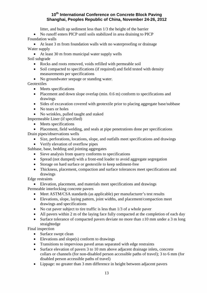
litter, and built up sediment less than 1/3 the height of the barrier • No runoff enters PICP until soils stabilized in area draining to PICP
Foundation walls • At least 3 m from foundation walls with no waterproofing or drainage
Water supply • At least 30 m from municipal water supply wells
Soil subgrade • Rocks and roots removed, voids refilled with permeable soil • Soil compacted to specifications (if required) and field tested with density
measurements per specifications • No groundwater seepage or standing water.
Geotextiles • Meets specifications • Placement and down slope overlap (min. 0.6 m) conform to specifications and
drawings • Sides of excavation covered with geotextile prior to placing aggregate base/subbase • No tears or holes • No wrinkles, pulled taught and staked
Impermeable Liner (if specified) • Meets specifications • Placement, field welding, and seals at pipe penetrations done per specifications
Drain pipes/observations wells • Size, perforations, locations, slope, and outfalls meet specifications and drawings • Verify elevation of overflow pipes
Subbase, base, bedding and jointing aggregates • Sieve analysis from quarry conforms to specifications • Spread (not dumped) with a front-end loader to avoid aggregate segregation • Storage on hard surface or geotextile to keep sediment-free • Thickness, placement, compaction and surface tolerances meet specifications and
drawings Edge restraints
• Elevation, placement, and materials meet specifications and drawings Permeable interlocking concrete pavers
• Meet ASTM/CSA standards (as applicable) per manufacturer’s test results • Elevations, slope, laying pattern, joint widths, and placement/compaction meet
drawings and specifications • No cut paver subject to tire traffic is less than 1/3 of a whole paver • All pavers within 2 m of the laying face fully compacted at the completion of each day • Surface tolerance of compacted pavers deviate no more than ±10 mm under a 3 m long
straightedge Final inspection
• Surface swept clean • Elevations and slope(s) conform to drawings • Transitions to impervious paved areas separated with edge restraints • Surface elevation of pavers 3 to 10 mm above adjacent drainage inlets, concrete
collars or channels (for non-disabled person accessible paths of travel); 3 to 6 mm (for disabled person accessible paths of travel)
• Lippage: no greater than 3 mm difference in height between adjacent pavers

10th International Conference on Concrete Block Paving Shanghai, Peoples Republic of China, November 24-26, 2012
14
• Bond lines for paver courses: ±13 mm over a 15 m string line • Stabilization of soil in area draining into permeable pavement (minimum 6 m wide
vegetative strips recommended) • Drainage swales or storm sewer inlets for emergency overflow. If storm sewer inlets
are used, confirm overflow drainage to them. • Runoff from non-vegetated soil diverted from PICP surface • Test surface for infiltration rate per specifications using ASTM C1701 Standard Test
Method for Infiltration Rate of In Place Pervious Concrete; minimum 2,500 mm/hr recommended
5. Chapter 5 - Maintenance The following provides a checklist for PICP maintenance.
• 1 to 2 times annually (typically spring/fall): vacuum surface, adjust vacuuming schedule per sediment loading and/or any sand deposits from winter. Use a regenerative air vacuum machine mounted on a truck.
• Winter: Remove snow with standard plow/snow blowing equipment; monitor ice on surface for reduced salt use than would typically be used on impervious pavements
• As needed, indicated by water ponding on surface immediately after a storm (paver joints or openings severely loaded with sediment): test surface infiltration rate using ASTM C1701. Vacuum to remove surface sediment and soiled aggregate (typically 13-25 mm), refill joints with clean aggregate, sweep surface clean and test infiltration rate again per C1701 to minimum 50% increase or minimum 250 mm/hr.
Many PICP installations will not receive routine surface vacuuming once or twice annually using a truck-mounted regenerative air vacuum machine. In such cases, the surface continues to take in water but at declining infiltration rates. At some point in the service life, the surface requires restorative maintenance cleaning. This is accomplished with a full vacuum machine (truck) which typically has at least two times the suction power of a regenerative air vacuum machine. A full vacuum machine can withdraw the stone and sediment from the openings, and the depth of their withdrawal is determined by the vacuum force and number of passes by the vacuum truck. After the jointing stones and sediment are removed to the depth at which the sediment has penetrated, the joints are refilled with clean stone and the paver surface is then swept clean of stones on the surface. Figure 5 illustrates a full vacuum machine making a cleaning pass and removing the jointing stones and sediment from a PICP surface. Annual Inspection checklist
• Replenish aggregate in joints if more than 13 mm from chamfer bottoms on paver surfaces
• Inspect vegetation around PICP perimeter for cover & soil stability, repair/replant as needed
• Inspect and repair all paver surface deformations exceeding 13 mm • Repair pavers offset by more than 6 mm above/below adjacent units or curbs, inlets
etc. • Replace cracked paver units impairing surface structural integrity • Check drains outfalls for free flow of water and outflow from observation well after a
major storm
6. Conclusions

10th International Conference on Concrete Block Paving Shanghai, Peoples Republic of China, November 24-26, 2012
15
The Interlocking Concrete Pavement Institute has published detailed industry guidelines for design, construction and maintenance of PICP. Validation of industry recommendations and experience are forthcoming in three arenas. The first two are within the American Society of Civil Engineers or ASCE. First, the ASCE Environment and Water Resources Institute will publish and manual of practice on permeable pavements in 2013. This document covers PICP, concrete grid pavement, pervious concrete and porous asphalt pavements, plus other lesser used systems. This publication will be for sale on the ASCE website and represents the state-of-the-art regarding North American practice.
Second, ASCE publishes many national standards on a range of civil engineering subjects. In 2010, ASCE published national standard 58-10 Structural Design of Interlocking Concrete Pavement for Municipal Streets and Roadways. As a logical next step, ASCE Transportation & Development Institute has initiated the development of a national design standard for PICP. This four year effort will result in a document that covers hydrologic and structural design, design details, as well as construction and maintenance guidelines. When completed, it will be a sister publication to ASCE 58-10. The third arena involves conducting full-scale structural testing of PICP at the University of California Pavement Research Center in Davis, The deliverables from this project are validated design charts for PICP using unstabilized, open-graded aggregate bases. The results will likely modify Table 1 and changes will be incorporated into the emerging ASCE design standard for PICP. 7. References AASHTO 1993. Guide for Design of Pavement Structures, American Association of State
Highway and Transportation Officials, Washington, DC. AASHTO 2004. Guide for Mechanistic-Empirical Design of New And Rehabilitated Pavement Structures, National Cooperative Highway Research Program, Transportation Research Board, National Research Council, American Association of State Highway and Transportation Officials, Washington, DC. AASHTO 2010. “Geotextile Specification for Highway Applications,” AASHTO Designation M-288, in Standard Specifications for Transportation Material and Methods of Sampling and
Figure 5. A true vacuum machine removes jointing stone and sediment from a five-year old PICP parking lot that has not received annual surface vacuuming with a regenerative air vacuum machine, The open joints are refilled with clean jointing stone.

10th International Conference on Concrete Block Paving Shanghai, Peoples Republic of China, November 24-26, 2012
16
Testing, Part IB: Specifications, 31st Edition, American Association for State Highway and Transportation Officials, Washington, DC. Attarian 2010. Attarian, J. L., “Greener Alleys” in Public Roads, Vol. 73, No. 6, U.S. Federal Highway Administration, U.S. Department of Transportation, Washington, DC, http://www.fhwa.dot.gov/publications/publicroads/10mayjun/05.cfm. Bäckström 2000. Bäckström, M., “Ground temperature in porous pavement during freezing and thawing,” ASCE Journal of Transportation Engineering, Volume 126, Issue 5, pp. 375-381, American Society of Civil Engineers, September/October 2000. Caraco 1997. Caraco, D. and Claytor, R., Stormwater BMP Design Supplement for Cold Climates, Center for Watershed Protection, Ellicott City, Maryland, 1997. Cedergren 1989. Cedergren, H. R., Seepage, Drainage, and Flow Nets, John Wiley & Sons, New York. Houle 2009. Houle, K.M., Roseen, R.M., Ballestero, T.P., Houle, J.J., “Performance Comparison of Porous Asphalt and Pervious Concrete Pavements in Northern Climates,” Stormcon 2009, Forster Publications, Santa Monica, California. Kevern 2009. Kevern, J.T., Schaefer, V.R. and Wang K., “Temperature Behavior of Pervious Concrete Systems,” Transportation Research Record: Journal of the Transportation Research Board No. 2098, Transportation Research Board of the National Academies, Washington, DC, 2009, p. 94-101. Smith 2011. Smith, D.R., Permeable Interlocking Concrete Pavements, 4th Edition, Interlocking Concrete Pavement Institute, Herndon, Virginia. Swan 2009. Swan, D.J, and Smith, D.R., “Development of the Permeable Design Pro Permeable Interlocking Concrete Pavement Design System,” in Proceedings of the 9th International Conference on Concrete Block Paving, Buenos Aires, Argentina, Argentinean Concrete Block Association, Cordoba, Argentina, October 2009. UNHSC 2008. “Porous Asphalt Fact Sheet,” issued by University of New Hampshire Stormwater Center, Durham, New Hampshire. Van Seters 2007. Van Seters, T., “Performance Evaluation of Permeable Pavement and a Bioretention Swale Seneca College, King City, Ontario,” Interim Report #3, Toronto and Region Conservation Authority, Downsview, Ontario, Canada, May 2007.