Embed Size (px)
Citation preview
1
Industry Experience with Power Generation
Options for Environmental Flows
Patrick March, Hydro Performance Processes Inc., Doylestown, Pennsylvania
Paul Jacobson, Electric Power Research Institute, Glenelg, Maryland
Abstract
Minimum flows, instream flows, fish-related flows, and other types of environmental flows can
represent a significant loss of generation due to direct discharges (e.g., sluiceways, spillways, re-regulation weirs, fish ladder flows, fish attraction flows, etc.) or due to inefficient turbine
operation at lower flows. Consequently, owners/operators of hydroelectric power facilities have
adopted a variety of strategies and technologies for providing environmental flows while also generating power.
This paper reviews and summarizes industry experience with environmental flow options that
also provide power generation, including environmental flow options with existing (primary) hydropower units, environmental flow options with dedicated environmental flow units, and
potential environmental flow options with emerging turbine technologies. The paper summarizes
the identified plants producing power while providing environmental flows with primary units,
with dedicated minimum/instream flow units, and with fish flow units. Additional plant details, including owner, site, turbine types, and the types of environmental flows, are provided. To date,
229 units providing environmental flows and generation have been identified. This total includes
181 primary generating units, 36 dedicated minimum flow units, and 12 fish flow units. The paper also provides recommendations for additional investigation and research.
Section 1: Introduction
1.1: Background
More than one thousand hydroelectric projects throughout the United States are subject to the
Federal Energy Regulatory Commission’s (FERC’s) licensing and relicensing process. The
licensing and relicensing process involves evaluating the effects of project operations on natural
resources, including streams and aquatic organisms. Flow-related issues are among the most
difficult and contentious aspects of the licensing and relicensing process [McManamay and
Bevelhimer, 2013; Bevelhimer et al., 2014]. Typically, FERC licenses require hydroelectric
power facilities to provide “minimum flows” to protect and enhance the downstream aquatic
environment. Minimum flows are one type of a larger category called “instream flows.”
Another more inclusive term, “environmental flows,” is also used.
In addition to FERC regulations, hydroelectric facilities are required to meet state water quality
standards, which vary from state to state. Under §401 of the Clean Water Act, individual states
issue Water Quality Certificates to hydroelectric plants. The §401 certificate is also a necessary
component of the FERC licensing and relicensing processes. In some regions, typical §401
Water Quality Certificates for hydroelectric power facilities include both minimum flow
requirements and minimum dissolved oxygen requirements.
2
1.2: Overview
Minimum flows, instream flows, fish-related flows, and other types of environmental flows can
represent a significant loss of generation due to direct discharges (e.g., sluiceways, spillways, re-
regulation weirs, fish ladder flows, fish attraction flows, etc.) or due to inefficient turbine
operation at lower flows. Consequently, owners/operators of hydroelectric power facilities have
adopted a variety of strategies and technologies for providing environmental flows while also
generating power.
Some owner/operators have adopted more efficient operational strategies with their primary
turbines, replaced primary turbines with designs better matched to the environmental flows, or
added new primary units to provide environmental flows during generation. Owners/operators
have also added small turbines at existing hydroelectric power facilities or designed new
facilities to include small turbines for minimum or environmental flows, including fish-related
flows. In addition, some emerging turbine technologies are approaching or achieving a
technology readiness level consistent with potential application as environmental flow options
with power generating capability.
Section 2 summarizes industry experience with the application of primary hydroelectric
generating units for providing environmental flows, including aerated discharges during normal
operations, minimum/instream flows, and minimum/instream flows with aeration. Section 2
includes two case studies. Section 3 summarizes industry experience with the application of
dedicated, typically small, hydroelectric generating units for providing environmental flows,
including minimum/instream flows, minimum/instream flows with aeration, and fish-related
flows. Section 3 includes three case studies. Section 4 discusses technology readiness levels,
provides a summary of emerging hydropower technologies and their potential applications for
environmental flows, and includes one case study.
The comprehensive report which provides the basis for this paper [EPRI, 2014] summarizes and
describes the identified plants producing power while providing environmental flows with
primary units, with dedicated minimum/instream flow units, and with fish-related flows.
Additional plant details, including owner, site, turbine types, and the types of environmental
flows, are provided in the figures [EPRI, 2014]. To date, 229 units providing environmental
flows and generation have been identified. This total includes 181 primary generating units, 36
dedicated minimum flow units (with one emerging turbine technology), and 12 fish flow units.
Section 2: Environmental Flows with Primary Units
2.1: Introduction
Some owner/operators have adopted more efficient operational strategies with their primary
turbines, replaced primary turbines with designs better matched to the environmental flows, or
added new primary units to provide environmental flows during generation. Section 2
summarizes industry experience with the application of primary hydroelectric generating units
for providing environmental flows, including aerated discharge during normal operations,
minimum/instream flows, minimum/instream flows with aeration, and fish flows. Section 2 also
includes two case studies (Comerford Unit 1, Conowingo Units 2 and 5) which provide examples

3
of successful application of primary units for environmental flows through unit re-design and
replacement.
2.2: Primary Units
Based on a review of license and relicense information from FERC’s eLibrary and on contacts
with owner/operators, consultants, and manufacturers, 181 primary units providing
environmental flows with power generation have been identified to date. Details of these units,
including owner and site, are provided in EPRI [2014]. Most of the identified primary units are
aerating units which seasonally provide increased dissolved oxygen levels in plant discharges
[EPRI, 2009; EPRI, 2011b; March, 2011; EPRI, 2013]. A total of 49 primary units provide
minimum flows, with 39 of the units providing minimum flows by periodic “pulse” discharges at
best efficiency.
Contact details for typical suppliers of primary units are provided in Table 2-1.
Table 2-1: Typical Suppliers of Primary Units
Supplier Location Turbine Types Supplier Website
Alstom HydroLevallois-Perret,
France
Vertical and horizontal Francis, Kaplan, Pelton, pit-type
Kaplan, diagonal flow, fixed propeller, bulb, S-type Kaplanalstom.com
Andritz Hydro Graz, AustriaVertical and horizontal Francis, Kaplan, Pelton, pit-type
Kaplan, diagonal flow, fixed propeller, bulb, S-type Kaplanandritz.com/hydro.htm
Dongfang Electric
CorporationChengdu, China Pelton, Francis, Kaplan dongfang.com.cn
Gilkes HydroKendal, United
KingdomVertical Francis, Pelton, Turgo gilkes.com
Toshiba Hydro Minato City, Japan Vertical Francis, Kaplan, pit-type Kaplan toshiba.co.jp
Voith HydroYork,
Pennsylvania
Vertical Francis, vertical Kaplan, Pelton, pit-type Kaplan,
diagonal flow, fixed propelleryork.voithhydro.com
Weir American HydroYork,
PennsylvaniaVertical Francis, vertical Kaplan, fixed propeller weirpowerindustrial.com
2.3: Case Study - Comerford Unit 1 Re-design and Replacement
TransCanada’s Comerford Plant is located on the Connecticut River near Littleton, New
Hampshire, and Waterford, Vermont. The Comerford, Moore, and McIndoes Plants make up the
Fifteen Mile Falls Hydroelectric Project (P-2077).
When the Fifteen Mile Falls Hydroelectric Project began operation under its new license in April
2002, three seasonal minimum flows were established: 818 cfs from June 1 through September
30; 1,145 cfs from October1 through March; and 1,635 cfs from April 1 through May 1. At the

4
time, the Comerford powerhouse (see Figure 2-1) included four Francis units, each rated at 35.1
MW for a head of 180 ft and a flow of 3,000 cfs.
Figure 2-1: View of Comerford Hydroelectric Plant and Dam (TransCanada Photo)
Design and installation of a replacement turbine for Comerford Unit 1 was completed in April
2007. Figure 2-2 provides a relative comparison between the original Comerford Unit 1 and the
replacement unit. Efficiencies in Figure 2-2 are relative to the new unit efficiency, and the flows
are relative to the midpoint of the new minimum flow range.
The replacement unit is designed for higher efficiency at the new minimum flows, as well as for
higher efficiency overall. Although the replacement unit for Comerford Unit 1 results in a
reduction of 18 MW of rated capacity, the new unit’s efficiency is more than 90% over the
minimum flow range from 800 cfs to 1600 cfs. The new unit also provides more efficient
generation at power levels corresponding to the intermediate flow ranges between the optimal
Unit 2, Unit 3, and Unit 4 flow increments of 2,900 cfs, 5,800 cfs, and 8,700 cfs. As a result of
the Unit 1 replacement, the annual generation for the Comerford Station has increased by 4.9%,
corresponding to 18,000 MWh/yr.

5
Figure 2-2: Comparison of Replacement Unit and Original Unit for Comerford Unit 1
2.4: Case Study - Conowingo Re-design and Replacement
Exelon Generation’s Conowingo Hydroelectric Plant (P-405) includes eleven primary units and
two small house units. Units 1 through 7 are Francis-type units, and Units 8 through 11 are
mixed-flow units. Conowingo typically operates to provide generation and river control services
to the PJM Interconnection (PJM), and the plant is dispatched by PJM. A view of the
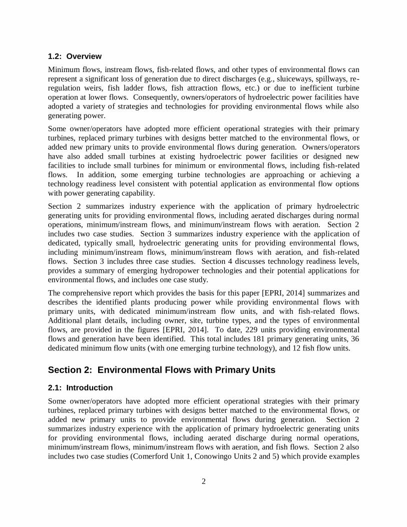
Conowingo Hydroelectric Plant and Dam is shown in Figure 2-3.
Conowingo’s primary units were not originally designed for the plant’s current seasonal
minimum flow levels. Replacement units, including distributed (i.e., trailing edge) aeration,
were designed for Conowingo Unit 2 and Unit 5 to match the lowest required minimum flow to
each unit’s best efficiency flow, providing more efficient generation and redundancy. Design
and installation of the replacement unit for Conowingo Unit 5 was completed in October 2005.
Unit 2 was completed in October 2008.
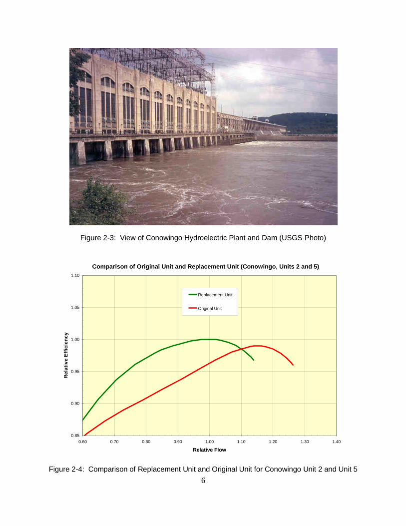
Figure 2-4 provides a relative comparison between the original Conowingo units and the
replacement units. Efficiencies in Figure 2-4 are relative to the new unit efficiency, and the
flows are relative to the lowest minimum flow rate. The replacement units provide higher
efficiency at the minimum flow levels, as well as for higher efficiency overall. As a result of the
Unit 2 and Unit 5 replacements, Conowingo can provide efficient, aerated minimum flows and
the annual generation has increased by 7,400 MWh/yr.
Comparison of Original Unit and Replacement Unit (Comerford Unit 1)
0.85
0.90
0.95
1.00
1.05
1.10
0.4 0.6 0.8 1.0 1.2 1.4 1.6 1.8 2.0 2.2 2.4 2.6
Relative Flow
Re
lati
ve
Eff
icie
nc
y
Replacement Unit
Original Unit
6
Figure 2-3: View of Conowingo Hydroelectric Plant and Dam (USGS Photo)
Figure 2-4: Comparison of Replacement Unit and Original Unit for Conowingo Unit 2 and Unit 5
Comparison of Original Unit and Replacement Unit (Conowingo, Units 2 and 5)
0.85
0.90
0.95
1.00
1.05
1.10
0.60 0.70 0.80 0.90 1.00 1.10 1.20 1.30 1.40
Relative Flow
Rela
tive
Eff
icie
ncy
Replacement Unit
Original Unit
7
Section 3: Environmental Flows with Dedicated Units
3.1: Introduction
Section 3 summarizes industry experience with the application of dedicated units for providing
environmental flows, including minimum/instream flows, minimum/instream flows with
aeration, and fish-related flows. Typically, the dedicated units are considerably smaller than the
primary units discussed in Section 2. Section 3 also includes two case studies.
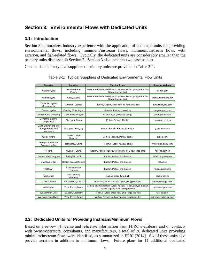
Contact details for typical suppliers of primary units are provided in Table 3-1.
Table 3-1: Typical Suppliers of Dedicated Environmental Flow Units
Supplier Location Turbine Types Supplier Website
Alstom HydroLevallois-Perret,
France
Vertical and horizontal Francis, Kaplan, Pelton, pit-type Kaplan,
S-type Kaplan, bulbalstom.com
Andritz Hydro Graz, AustriaVertical and horizontal Francis, Kaplan, Pelton, pit-type Kaplan,
S-type Kaplan, bulbandritz.com/hydro.htm
Canadian Hydro
ComponentsAlmonte, Canada Francis, Kaplan, axial flow, pit-type axial flow canadianhydro.com
Canyon Hydro Deming, Washington Francis, Pelton, cross-flow canyonhydro.com
Cornell Pump Company Clackamas, Oregon Francis-type (reversed pump) cornellpump.com
Dongfang Electric
CorporationChengdu, China Pelton, Francis, Kaplan dongfang.com.cn
Ganz Engineering and
Energy Production
Machinery
Budapest, Hungary Pelton, Francis, Kaplan, tube-type ganz-eem.com
Gilkes HydroKendal, United
KingdomVertical Francis, Pelton, Turgo gilkes.com
Hangzhou Hydrotu
Engineering Co.Hangzhou, China Pelton, Francis, Kaplan, Turgo hydrotu.en.ec21.com
Hecong Guangxi, China Kaplan, Pelton, Francis, cross-flow, axial flow, tube-type hecong.com.cn
James Leffel Company Springfield, Ohio Kaplan, Pelton, and Francis leffelcompany.com
Mavel Americas Boston, Massachusetts Kaplan, Pelton, and Francis mavel.cz
NORCANCarleton Place,
CanadaKaplan, Pelton, and Francis norcanhydro.com
OssbergerWeissenburg,
GermanyKaplan, cross-flow, bulb ossberger.de
Toshiba Hydro Fuchunjiang, China Vertical Francis, vertical Kaplan, pit-type Kaplan en.toshiba-thpc.com
Voith Hydro York, PennsylvaniaVertical and horizontal Francis, Kaplan, Pelton, pit-type Kaplan,
S-type Kaplan, bulb, fixed propelleryork.voithhydro.com
Wasserkraft Volk Gutach, Germany Pelton, Francis, cross-flow, and Turgo turbines wkv-ag.com
Weir American Hydro York, Pennsylvania Vertical Francis, vertical Kaplan, fixed propeller weirpowerindustrial.com
3.2: Dedicated Units for Providing Instream/Minimum Flows
Based on a review of license and relicense information from FERC’s eLibrary and on contacts
with owner/operators, consultants, and manufacturers, a total of 36 dedicated units providing
minimum/instream flows were identified, as summarized in EPRI [2014]. Six of these units also
provide aeration in addition to minimum flows. Future plans for 11 additional dedicated

8
minimum flow units were identified. In addition, 6 dedicated units were identified as licensed
but never installed due to economics, and 4 dedicated instream/minimum flow units were
removed from service due to equipment failure.
3.3: Case Study - Osage Re-design and Replacement of House Units
Ameren Missouri’s (Ameren’s) Osage Plant (Osage) includes eight Francis-type turbines, each
capable of aerating operation. Osage typically operates to provide generation and ancillary
services to the Midwest Independent System Operator (MISO). A view of Bagnell Dam, the
Osage Plant, and the Lake of the Ozarks is shown in Figure 3-1.
Figure 3-1: Bagnell Dam, Osage Plant, and Lake of the Ozarks
Originally, the Osage Plant included two small station service units, manufactured by Allis-
Chalmers. Each of the station service units operated at 170 cfs and approximately 60%
efficiency. To meet the minimum flow and dissolved oxygen requirements in the new FERC
license, Ameren Missouri replaced the station service units in 2010 with Weir American Hydro
units including peripheral aeration. Each of the replacement units is rated for 3.1 MW and 450
cfs at 90 ft of head, and the units operate at an efficiency of approximately 90% [March, 2011].
Figure 3-2 provides a cross-sectional view of the turbines, Figure 3-3 shows a photograph of a
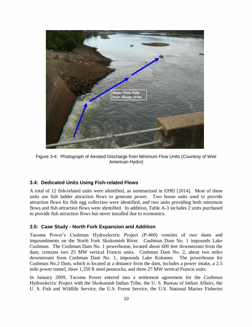
turbine and its air outlets after 10,000 hours of operation, and Figure 3-4 shows the aerated
discharge from the minimum flow units.

9
Figure 3-2: Cross-sectional View of Turbine and Peripheral Aeration System (Courtesy of Weir American Hydro)
Figure 3-3: Photograph of Turbine and Peripheral Aeration System (Courtesy of Weir American Hydro)
10
Figure 3-4: Photograph of Aerated Discharge from Minimum Flow Units (Courtesy of Weir American Hydro)
3.4: Dedicated Units Using Fish-related Flows
A total of 12 fish-related units were identified, as summarized in EPRI [2014]. Most of these
units use fish ladder attraction flows to generate power. Two house units used to provide
attraction flows for fish egg collection were identified, and two units providing both minimum
flows and fish attraction flows were identified. In addition, Table A-3 includes 2 units purchased
to provide fish attraction flows but never installed due to economics.
3.5: Case Study - North Fork Expansion and Addition
Tacoma Power’s Cushman Hydroelectric Project (P-460) consists of two dams and
impoundments on the North Fork Skokomish River. Cushman Dam No. 1 impounds Lake
Cushman. The Cushman Dam No. 1 powerhouse, located about 600 feet downstream from the
dam, contains two 25 MW vertical Francis units. Cushman Dam No. 2, about two miles
downstream from Cushman Dam No. 1, impounds Lake Kokanee. The powerhouse for
Cushman No.2 Dam, which is located at a distance from the dam, includes a power intake, a 2.5
mile power tunnel, three 1,350 ft steel penstocks, and three 27 MW vertical Francis units.
In January 2009, Tacoma Power entered into a settlement agreement for the Cushman
Hydroelectric Project with the Skokomish Indian Tribe, the U. S. Bureau of Indian Affairs, the
U. S. Fish and Wildlife Service, the U.S. Forest Service, the U.S. National Marine Fisheries
11
Service (NMFS), the Washington Department of Ecology, and the Washington Department of
Fish and Wildlife. Late in January 2009, the Tacoma Power submitted a license amendment
application to FERC for the construction of a new powerhouse at the base of Cushman No. 2
Dam. Construction of the new North Fork Skokomish powerhouse was completed in 2013
[McCarty, 2014].
The North Fork Skokomish powerhouse includes two 1.8 MW Francis units generating a total of
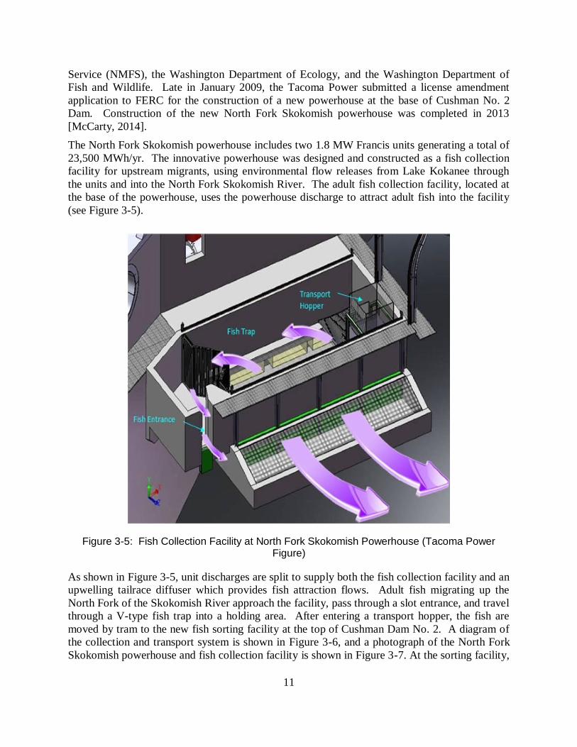
23,500 MWh/yr. The innovative powerhouse was designed and constructed as a fish collection
facility for upstream migrants, using environmental flow releases from Lake Kokanee through
the units and into the North Fork Skokomish River. The adult fish collection facility, located at
the base of the powerhouse, uses the powerhouse discharge to attract adult fish into the facility
(see Figure 3-5).
Figure 3-5: Fish Collection Facility at North Fork Skokomish Powerhouse (Tacoma Power Figure)
As shown in Figure 3-5, unit discharges are split to supply both the fish collection facility and an
upwelling tailrace diffuser which provides fish attraction flows. Adult fish migrating up the
North Fork of the Skokomish River approach the facility, pass through a slot entrance, and travel
through a V-type fish trap into a holding area. After entering a transport hopper, the fish are
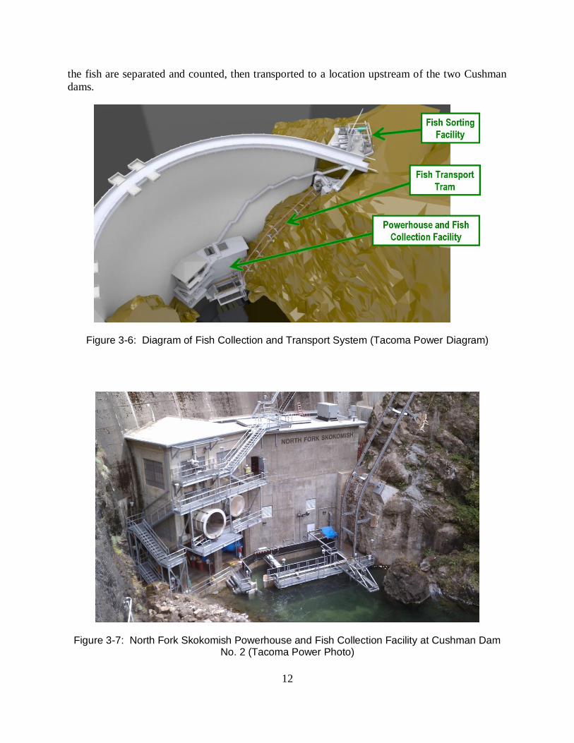
moved by tram to the new fish sorting facility at the top of Cushman Dam No. 2. A diagram of
the collection and transport system is shown in Figure 3-6, and a photograph of the North Fork
Skokomish powerhouse and fish collection facility is shown in Figure 3-7. At the sorting facility,
12
the fish are separated and counted, then transported to a location upstream of the two Cushman
dams.
Figure 3-6: Diagram of Fish Collection and Transport System (Tacoma Power Diagram)
Figure 3-7: North Fork Skokomish Powerhouse and Fish Collection Facility at Cushman Dam No. 2 (Tacoma Power Photo)
13
Tacoma Power has built a new floating fish collection facility, attached to Cushman No. 1 Dam,
for Lake Cushman. Juvenile fish migrating downstream are collected, transported around the
Cushman dams, and released into the North Fork Skokomish River at the base of Cushman No. 2
Dam to continue their migration. Discharges from the North Fork Skokomish units also provide
the instream flow requirements.
3.6: Case Study - Dalles North Shore Fishway Addition
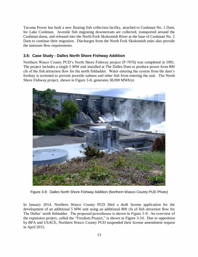
Northern Wasco County PUD’s North Shore Fishway project (P-7076) was completed in 1991.
The project includes a single 5 MW unit installed at The Dalles Dam to produce power from 800
cfs of the fish attraction flow for the north fishladder. Water entering the system from the dam’s
forebay is screened to prevent juvenile salmon and other fish from entering the unit. The North
Shore Fishway project, shown in Figure 3-8, generates 38,000 MWh/yr.
Figure 3-8: Dalles North Shore Fishway Addition (Northern Wasco County PUD Photo)
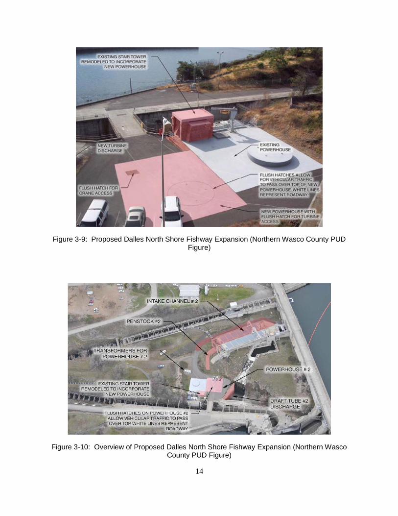
In January 2014, Northern Wasco County PUD filed a draft license application for the
development of an additional 5 MW unit using an additional 800 cfs of fish attraction flow for
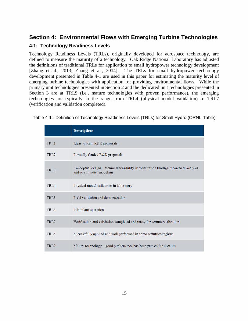
The Dalles’ north fishladder. The proposed powerhouse is shown in Figure 3-9. An overview of
the expansion project, called the “Freedom Project,” is shown in Figure 3-10. Due to opposition
by BPA and USACE, Northern Wasco County PUD suspended their license amendment request
in April 2015.
14
Figure 3-9: Proposed Dalles North Shore Fishway Expansion (Northern Wasco County PUD Figure)
Figure 3-10: Overview of Proposed Dalles North Shore Fishway Expansion (Northern Wasco County PUD Figure)
15
Section 4: Environmental Flows with Emerging Turbine Technologies
4.1: Technology Readiness Levels
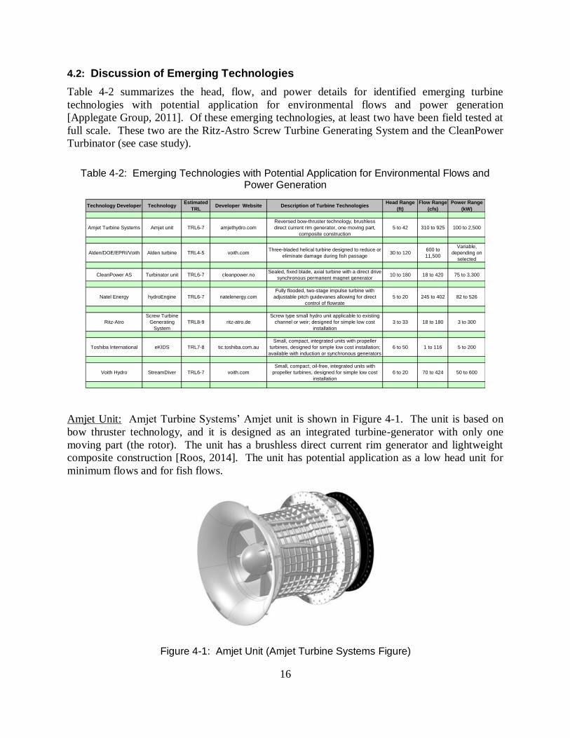
Technology Readiness Levels (TRLs), originally developed for aerospace technology, are
defined to measure the maturity of a technology. Oak Ridge National Laboratory has adjusted
the definitions of traditional TRLs for application to small hydropower technology development
[Zhang et al., 2013; Zhang et al., 2014]. The TRLs for small hydropower technology
development presented in Table 4-1 are used in this paper for estimating the maturity level of
emerging turbine technologies with application for providing environmental flows. While the
primary unit technologies presented in Section 2 and the dedicated unit technologies presented in
Section 3 are at TRL9 (i.e., mature technologies with proven performance), the emerging
technologies are typically in the range from TRL4 (physical model validation) to TRL7
(verification and validation completed).
Table 4-1: Definition of Technology Readiness Levels (TRLs) for Small Hydro (ORNL Table)
16
4.2: Discussion of Emerging Technologies
Table 4-2 summarizes the head, flow, and power details for identified emerging turbine
technologies with potential application for environmental flows and power generation
[Applegate Group, 2011]. Of these emerging technologies, at least two have been field tested at
full scale. These two are the Ritz-Astro Screw Turbine Generating System and the CleanPower
Turbinator (see case study).
Table 4-2: Emerging Technologies with Potential Application for Environmental Flows and Power Generation
Technology Developer TechnologyEstimated
TRLDeveloper Website Description of Turbine Technologies
Head Range
(ft)
Flow Range
(cfs)
Power Range
(kW)
Amjet Turbine Systems Amjet unit TRL6-7 amjethydro.com
Reversed bow-thruster technology, brushless
direct current rim generator, one moving part,
composite construction
5 to 42 310 to 925 100 to 2,500
Alden/DOE/EPRI/Voith Alden turbine TRL4-5 voith.comThree-bladed helical turbine designed to reduce or
eliminate damage during fish passage30 to 120
600 to
11,500
Variable,
depending on
selected
CleanPower AS Turbinator unit TRL6-7 cleanpower.noSealed, fixed blade, axial turbine with a direct drive
synchronous permanent magnet generator10 to 180 18 to 420 75 to 3,300
Natel Energy hydroEngine TRL6-7 natelenergy.com
Fully flooded, two-stage impulse turbine with
adjustable pitch guidevanes allowing for direct
control of flowrate
5 to 20 245 to 402 82 to 526
Ritz-Atro
Screw Turbine
Generating
System
TRL8-9 ritz-atro.de
Screw type small hydro unit applicable to existing
channel or weir; designed for simple low cost
installation
3 to 33 18 to 180 3 to 300
Toshiba International eKIDS TRL7-8 tic.toshiba.com.au
Small, compact, integrated units with propeller
turbines, designed for simple low cost installation;
available with induction or synchronous generators
6 to 50 1 to 116 5 to 200
Voith Hydro StreamDiver TRL6-7 voith.com
Small, compact, oil-free, integrated units with
propeller turbines, designed for simple low cost
installation
6 to 20 70 to 424 50 to 600
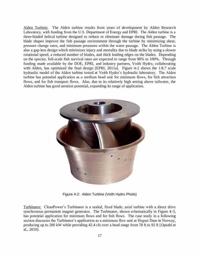
Amjet Unit: Amjet Turbine Systems’ Amjet unit is shown in Figure 4-1. The unit is based on
bow thruster technology, and it is designed as an integrated turbine-generator with only one
moving part (the rotor). The unit has a brushless direct current rim generator and lightweight
composite construction [Roos, 2014]. The unit has potential application as a low head unit for
minimum flows and for fish flows.
Figure 4-1: Amjet Unit (Amjet Turbine Systems Figure)
17
Alden Turbine: The Alden turbine results from years of development by Alden Research
Laboratory, with funding from the U.S. Department of Energy and EPRI. The Alden turbine is a
three-bladed helical turbine designed to reduce or eliminate damage during fish passage. The
blade shapes improve the fish passage environment through the turbine by minimizing shear,
pressure change rates, and minimum pressures within the water passage. The Alden Turbine is
also a gap-less design which minimizes injury and mortality due to blade strike by using a slower
rotational speed, a reduced number of blades, and thick leading edges on the blades. Depending
on the species, full-scale fish survival rates are expected to range from 98% to 100%. Through
funding made available by the DOE, EPRI, and industry partners, Voith Hydro, collaborating
with Alden, has optimized the final design [EPRI, 2011a]. Figure 4-2 shows the 1:8.7 scale
hydraulic model of the Alden turbine tested at Voith Hydro’s hydraulic laboratory. The Alden
turbine has potential application as a medium head unit for minimum flows, for fish attraction
flows, and for fish transport flows. Also, due to its relatively high setting above tailwater, the
Alden turbine has good aeration potential, expanding its range of application.
Figure 4-2: Alden Turbine (Voith Hydro Photo)
Turbinator: CleanPower’s Turbinator is a sealed, fixed blade, axial turbine with a direct drive
synchronous permanent magnet generator. The Turbinator, shown schematically in Figure 4-3,
has potential application for minimum flows and for fish flows. The case study in a following
section discusses the Turbinator’s application as a minimum flow unit at Hegset Dam in Norway,
producing up to 280 kW while providing 42.4 cfs over a head range from 78 ft to 92 ft [Opsahl et
al., 2010].

18
Figure 4-3: CleanPower’s Turbinator Unit (CleanPower Figure)
hydroEngine: Natel Energy’s hydroEngine is a unique two stage impulse turbine with adjustable
pitch guide vanes for direct control of flow rate [Wagman, 2013]. The hydroEngine is shown
schematically in Figure 4-4. This hydropower machine has potential application for low head
minimum flows and for low head fish flows.
Screw Turbine Generating System: Ritz-Atro’s Screw Turbine Generating System is one
example of a screw-type small hydro unit applicable to an existing channel or weir. The system
is designed for simple operation and maintenance and for low installation costs. An example of
an operating Ritz-Atro system is provided in Figure 4-5. The screw unit has potential application
for low head minimum flows and for low head fish transport flows. European experience
suggests that smolts, adult fish, and eels are transported through screw-type turbines and pumps
with little or no damage [Kibel, 2008; Kibel et al., 2009].

19
Figure 4-4: Natel Energy’s hydroEngine (Natel Energy Figure)
Figure 4-5: Ritz-Atro’s Screw Turbine Generating System (Ritz-Atro Photo)

20
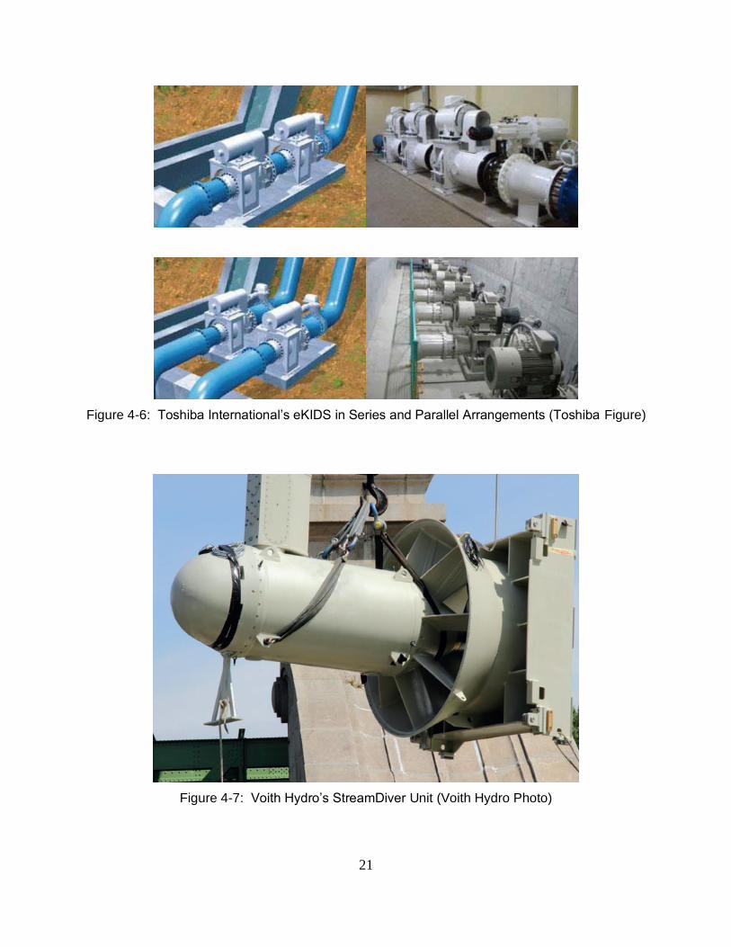
eKIDS: Toshiba International’s eKIDS is the trade name for a family of small, compact,
integrated units with propeller turbines, designed for low cost installation and available with
induction or synchronous generators. Figure 4-6 shows multiple eKIDS units in series and
parallel configurations. The eKIDS units have potential application for low to medium head
minimum flows, for conduit flows, and for low to medium head fish attraction and transport
flows.
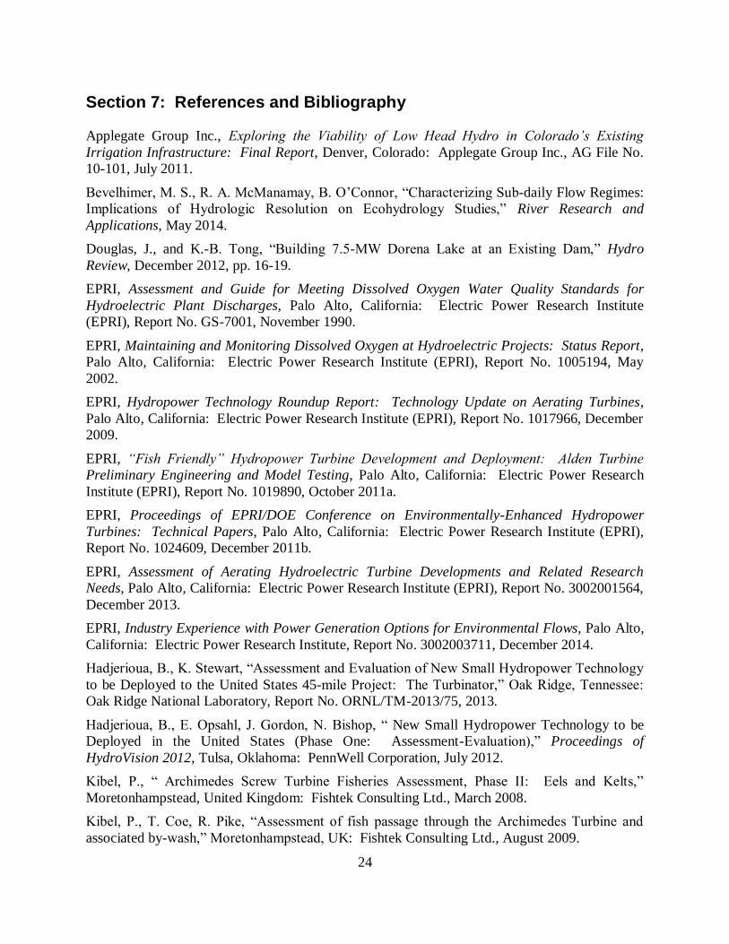
StreamDiver: Voith Hydro’s StreamDiver is a small, compact, oil-free integrated unit with a
propeller turbine, designed for simple, low cost installation. The unit has potential application
for low head minimum flows and for low head fish flows. The StreamDiver unit is shown in
Figure 4-7.
Case Study – Hegset Minimum Flow Unit
CleanPower’s Turbinator unit was developed in Norway within the European Union context for
hydropower, including high energy prices, consistent policies promoting renewable energy, and
environmental responsibility embodied in the Water Framework Directive of 2000 (WFD). As a
consequence of WFD goals, environmental flow releases from many hydropower plants will
increase, typically during the licensing or relicensing processes [Opsahl et al., 2010].
The Turbinator is based on rim-driven thruster technology developed for the shipping industry.
The unit integrates a sealed, fixed blade, axial flow turbine with a direct drive synchronous
permanent magnet generator, as shown in Figure 4-3. Because the generator rotor is designed
with permanent magnets fixed directly to the outside of the turbine, the unit has only one rotating
part. Installation is simple, and no power house is required [Opsahl et al., 2010; Hadjerioua et
al., 2012; Hadjerioua and Stewart, 2013]. On its upstream side, the Turbinator unit connects to
an inflow pipe with a bolted flange, and on its downstream side, the unit is bolted to a draft tube
pipe (see Figure 4-8).
A full scale demonstration of the Turbinator was completed at Statkraft’s Hegset Dam in 2010
(see Figure 4-9). Hegset Dam, located on the Nea River in Norway, has a minimum flow
requirement of 53 cfs during five summer months. The compliance point is located 3.7 miles
downstream from the dam. The Turbinator unit provided 42.5 cfs at an average head of 80 ft.,
and inflows from downstream creeks provided the residual flow. During its 1,500 hours of
installation, the demonstration unit was operational more than 98% of the time and generated
350 MWh, with an average power level of 234 kW [Opsahl et al., 2010].
21
Figure 4-6: Toshiba International’s eKIDS in Series and Parallel Arrangements (Toshiba Figure)
Figure 4-7: Voith Hydro’s StreamDiver Unit (Voith Hydro Photo)

22
Figure 4-8: Turbinator Operation During Initial Testing (CleanPower Photo)
Figure 4-9: Turbinator Minimum Flow Installation at Hegset Dam (CleanPower Photo)

23
Section 5: Summary and Recommendations
5.1: Summary
This paper reviews and summarizes industry experience with environmental flow options that
also provide power generation, including options with existing (primary) hydropower units,
options with dedicated environmental flow units for minimum flows and fish flows, and potential
options with emerging turbine technologies. The paper provides examples of plants with power-
generating environmental flows and presents plant details, including owner, site, turbine types,
and types of environmental flows. To date, 229 units providing environmental flows and
generation have been identified. This total includes 181 primary generating units, 36 dedicated
minimum flow units, and 12 fish flow units.
5.2: Recommendations for Additional Work
Based on results from this investigation, recommendations include:
1. Continue to survey turbine manufacturers, consulting firms, regulators, and utilities
and to compile: (a) cost information, including capital costs, installation costs, and
O&M costs associated with power-generating environmental flow technologies and
facilities; (b) hydraulic and environmental performance data for power-generating
environmental flow technologies; and (c) additional information on technology
readiness levels and applicability for emerging power-generating environmental flow
technologies.
2. Share the collected information on existing and emerging power-generating
environmental flow technologies with the hydropower industry through periodic
update reports, webinars, and a well-publicized web site.
3. Establish a national and international database of collected information on existing
and emerging power-generating environmental flow technologies. The database
could be funded by DOE, EPRI, USACE, the International Energy Association, or
other appropriate sponsor and maintained by a national laboratory with related
experience, such as Oak Ridge National Laboratory.
4. Support the development of a web-based data base providing centralized information
on hydropower-related federal and state incentives for “green” and renewable energy
with applicability to power-generating environmental flow technologies and facilities.
5. Support fish passage and eel passage research with existing and emerging power-
generating environmental flow technologies.
6. Solicit additional information on industry experience with power-generating
environmental flow technologies from African, Asian, European, and South
American utilities and agencies as environmental flow technologies are applied in
those areas.
24
Section 7: References and Bibliography Applegate Group Inc., Exploring the Viability of Low Head Hydro in Colorado’s Existing
Irrigation Infrastructure: Final Report, Denver, Colorado: Applegate Group Inc., AG File No.
10-101, July 2011.
Bevelhimer, M. S., R. A. McManamay, B. O’Connor, “Characterizing Sub-daily Flow Regimes:
Implications of Hydrologic Resolution on Ecohydrology Studies,” River Research and
Applications, May 2014.
Douglas, J., and K.-B. Tong, “Building 7.5-MW Dorena Lake at an Existing Dam,” Hydro
Review, December 2012, pp. 16-19.
EPRI, Assessment and Guide for Meeting Dissolved Oxygen Water Quality Standards for
Hydroelectric Plant Discharges, Palo Alto, California: Electric Power Research Institute
(EPRI), Report No. GS-7001, November 1990.
EPRI, Maintaining and Monitoring Dissolved Oxygen at Hydroelectric Projects: Status Report,
Palo Alto, California: Electric Power Research Institute (EPRI), Report No. 1005194, May
2002.
EPRI, Hydropower Technology Roundup Report: Technology Update on Aerating Turbines,
Palo Alto, California: Electric Power Research Institute (EPRI), Report No. 1017966, December
2009.
EPRI, “Fish Friendly” Hydropower Turbine Development and Deployment: Alden Turbine
Preliminary Engineering and Model Testing, Palo Alto, California: Electric Power Research
Institute (EPRI), Report No. 1019890, October 2011a.
EPRI, Proceedings of EPRI/DOE Conference on Environmentally-Enhanced Hydropower
Turbines: Technical Papers, Palo Alto, California: Electric Power Research Institute (EPRI),
Report No. 1024609, December 2011b.
EPRI, Assessment of Aerating Hydroelectric Turbine Developments and Related Research
Needs, Palo Alto, California: Electric Power Research Institute (EPRI), Report No. 3002001564,
December 2013.
EPRI, Industry Experience with Power Generation Options for Environmental Flows, Palo Alto,
California: Electric Power Research Institute, Report No. 3002003711, December 2014.
Hadjerioua, B., K. Stewart, “Assessment and Evaluation of New Small Hydropower Technology
to be Deployed to the United States 45-mile Project: The Turbinator,” Oak Ridge, Tennessee:
Oak Ridge National Laboratory, Report No. ORNL/TM-2013/75, 2013.
Hadjerioua, B., E. Opsahl, J. Gordon, N. Bishop, “ New Small Hydropower Technology to be
Deployed in the United States (Phase One: Assessment-Evaluation),” Proceedings of
HydroVision 2012, Tulsa, Oklahoma: PennWell Corporation, July 2012.
Kibel, P., “ Archimedes Screw Turbine Fisheries Assessment, Phase II: Eels and Kelts,”
Moretonhampstead, United Kingdom: Fishtek Consulting Ltd., March 2008.
Kibel, P., T. Coe, R. Pike, “Assessment of fish passage through the Archimedes Turbine and
associated by-wash,” Moretonhampstead, UK: Fishtek Consulting Ltd., August 2009.

25
March, P., “Hydraulic and Environmental Performance of Aerating Turbine Technologies,”
Proceedings of EPRI/DOE Conference on Environmentally-Enhanced Hydropower Turbines:
Technical Papers, Palo Alto, California: Electric Power Research Institute (EPRI), Report No.
1024609, December 2011.
McCarty, P., “Removal by Addition on the Skokomish River,” Hydro Review, November 2014,
pp. 16-22.
McIntosh, D., D. Cherwinski, and T. Kahl, “Hardy Unit No. 3 Turbine Rehabilitation,”
Proceedings of HydroVision 2010, Tulsa, Oklahoma: PennWell Corporation, July 2010.
McManamay, R. A., M. S. Bevelhimer, “A Holistic Framework for Environmental Flows
Determination in Hydropower Contexts,” Oak Ridge, Tennessee: Oak Ridge National
Laboratory, Report No. ORNL/TM-2013/159, April 2013.
NAI and GSE, Seasonal and Diurnal Water Quality in Conowingo Pond and below Conpowingo
Dam, Drumore, Pennsylvania: Normandeau Associates Inc. (NAI) and Gomez and Sullivan
Engineers (GSE), Exelon Generation Report, March 2011.
Opsahl, E., E. Holmen, O. Krovel, “Installing the Turbinator,” International Water Power &
Dam Construction, November 2010, pp. 22-24.
Rohland, K. M., J. M. Foust, G. D. Lewis, and J. C. Sigmon, “Aerating Turbines for Duke
Energy’s New Bridgewater Powerhouse,” Hydro Review, April 2010, pp. 58-65.
Roos, P., “Thinking Inside the Box,” International Water Power & Dam Construction, July
2014.
TVA, “Table Rock Project: House Unit Oxygen Injection System, Conceptual Study Report,”
Knoxville, Tennessee: Tennessee Valley Authority (TVA), September 2010.
USBR, “Hydropower Turbine Retrofit Improves Dissolved Oxygen Levels,” Western Water and
Power Solution Bulletin No. 32, Denver, Colorado: U. S. Bureau of Reclamation (USBR),
September 2011.
Wagman, D., “Small Hydro, Big Opportunity,” Power, May 2013.
Zhang, Q. F., B. T. Smith, W. Zhang, “Small Hydropower Cost Reference Model,” Oak Ridge,
Tennessee: Oak Ridge National Laboratory, Report No. ORNL/TM-2012/501, October 2012.
Zhang, Q. F., P. O’Connor, S. DeNeale, and R. Martinez, “Method for Assessing and Selecting
New Small Hydro Technology,” Hydro Review, November 2014, pp. 36-43.
Section 8: Authors
Patrick A. March is President and Principal Consultant for Hydro Performance Processes Inc.
(2394 Turk Road, Doylestown, PA 18901; [email protected]; 865.603.0175).
Paul Jacobson is Senior Technical Leader in Environment at the Electric Power Research Institute, where he leads EPRI’s activities related to marine and hydrokinetic technologies and environmental aspects of hydropower (Glenelg, MD 21737; [email protected]; 410.489.3675).