Embed Size (px)
Citation preview

Siemens IK PI · 2015
66/2 Introduction
6/3 Industrial Wireless LAN (IWLAN)6/3 Introduction6/6 Application examples6/10 Overview of network components
6/13 IWLAN – Access Points IEEE 802.11n
6/13 Overview6/16 SCALANCE W788 RJ45
for use in control cabinet6/23 SCALANCE W788 M12 for indoor use6/30 SCALANCE W788 M12 EEC
for enhanced environmental conditions6/35 SCALANCE W786 RJ45
for outdoor use6/42 SCALANCE W786 SFP
for outdoor use6/47 SCALANCE W774 RJ45
for use in control cabinet6/52 SCALANCE W774 M12 EEC
for enhanced environmental conditions6/57 SCALANCE W761 RJ45
for the Control Cabinet
6/62 IWLAN – Controller and Controller Access PointsIEEE 802.11n
6/62 Overview6/66 SCALANCE WLC711
industrial wireless LAN controller6/70 SCALANCE W788 RJ45 controller
access points for use in control cabinet6/74 SCALANCE W788C M12 controller
access points for indoor use6/78 SCALANCE W788C M12 EEC
for enhanced environmental conditions6/83 SCALANCE W786 RJ45 controller
access points for outdoor use6/88 SCALANCE W786C SFP controller
access points for outdoor use
6/92 IWLAN – Client ModulesIEEE 802.11n
6/92 Overview6/95 SCALANCE W748 RJ45
for use in control cabinet6/100 SCALANCE W748 M12
for indoor use6/105 SCALANCE W734 RJ45
for use in control cabinet6/110 SCALANCE W722 RJ45
for use in control cabinet6/114 SCALANCE W721 RJ45
for use in control cabinet
6/118 IWLAN – Accessories6/118 IWLAN antennas6/134 IWLAN RCoax cables6/139 IWLAN cabling technology6/148 KEY-PLUG W7006/150 Power Supply PS791-2DC
and PS791-2AC
6/152 Wireless Devices6/152 SIMATIC Mobile Panel 277(F) IWLAN
6/162 WirelessHART6/162 General6/163 SITRANS P280
for gauge and absolute pressure6/167 SITRANS TF280, WirelessHART6/170 SITRANS AW200 WirelessHART
adapter6/174 SITRANS AW210 WirelessHART
adapter6/178 IE/WSN-PA LINK
Industrial Wireless Communication
Kap_06_IWC_en.book Seite 1 Dienstag, 7. Oktober 2014 1:47 13
© Siemens AG 2014
6/2 Siemens IK PI · 2015
Industrial Wireless Communication
Introduction
6
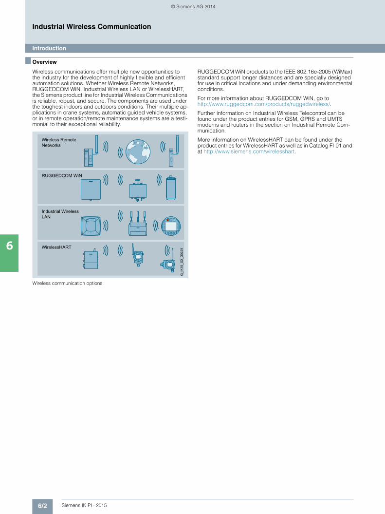
■ Overview
Wireless communications offer multiple new opportunities to the industry for the development of highly flexible and efficient automation solutions. Whether Wireless Remote Networks,RUGGEDCOM WiN, Industrial Wireless LAN or WirelessHART, the Siemens product line for Industrial Wireless Communications is reliable, robust, and secure. The components are used under the toughest indoors and outdoors conditions. Their multiple ap-plications in crane systems, automatic guided vehicle systems, or in remote operation/remote maintenance systems are a testi-monial to their exceptional reliability.
Wireless communication options
RUGGEDCOM WiN products to the IEEE 802.16e-2005 (WiMax) standard support longer distances and are specially designed for use in critical locations and under demanding environmental conditions.
For more information about RUGGEDCOM WiN, go to http://www.ruggedcom.com/products/ruggedwireless/.
Further information on Industrial Wireless Telecontrol can be found under the product entries for GSM, GPRS and UMTS modems and routers in the section on Industrial Remote Com-munication.
More information on WirelessHART can be found under the product entries for WirelessHART as well as in Catalog FI 01 and at http://www.siemens.com/wirelesshart.
Wireless Remote Networks
WirelessHART
RUGGEDCOM WiN
Industrial Wireless LAN
G_I
K10
_XX
_302
29
Kap_06_IWC_en.book Seite 2 Dienstag, 7. Oktober 2014 1:47 13
© Siemens AG 2014

6/3Siemens IK PI · 2015
Industrial Wireless CommunicationIndustrial Wireless LAN (IWLAN)
Introduction
6
■ Overview
SCALANCE W – wireless communication with Industrial Wireless LAN
The SCALANCE W products provide a combination of reliability, ruggedness and security in a single product:• For use by industrial and automation customers• For outdoor use under demanding climatic conditions• For low-cost integration in the control cabinet or in devices
The Industrial Wireless LAN (IWLAN) technology provides an extension to the IEEE 802.11 standard that is particularly suited to demanding industrial applications with real-time and redun-dancy requirements. This provides customers with a unique wireless network, both for process-critical data and for uncritical communication. SCALANCE W products distinguish themselves by the reliability of their radio channel and the rugged type of construction with high requirements with respect to mechanical durability for which SIMATIC is known. To protect against unauthorized access, the products have modern standard mechanisms for user identification (authentication) and data encryption, and can at the same time be easily integrated into existing security concepts.
Wireless infrastructure
Instead of copper cables and fiber-optic cables, wireless trans-mission techniques use radio waves. The propagation charac-teristics of the electromagnetic waves can differ considerably and depend on the spatial environment with the installed wire-less infrastructure.
SCALANCE W modules use techniques such as MIMO, high-quality receivers, and fault-tolerant modulation procedures to improve signal quality and to prevent interruption of wireless communication. Extensions to the IEEE 802.11 standard also permit reliable, wireless transmission from PROFINET, form the basis for wireless safety applications and the transmission of video data with extremely short reply and update data.
Network solution with IWLAN
Mobile end devices, for example, allow a continuous information flow from the management level down to the production level.
The IE/PB Link PN IO with SCALANCE W client modules (e.g. W722) is available for wireless-based connection of PROFIBUS devices.
This means that information can be provided quickly, reliably and easily at the right place and at the right time by wireless.
Ruggedness and industrial suitability
The SCALANCE W products can be exposed to fluctuations in the extended temperature range, or to continuous contact with dust and water. Rugged enclosure and mechanical protection against shock and vibration allow use in harsh industrial environ-ments.
EEC (Enhanced Environmental Conditions) series devices are also specially strengthened (coated printed circuit boards resist condensation, increased temperature range) and can also be used in railway applications. Accessories such as antennas, power supply units and cabling are also part of this concept and are suitable for use in industry.
Power and data are transferred over one cable with Power-over-Ethernet (PoE), saving investment and maintenance costs.
The C-PLUG (configuration plug) swap medium stores engineer-ing and configuration data, making device replacement possible in a short time and without specially trained personnel. This minimizes downtimes and saves training costs.
In addition to the functions of the C-PLUG, the KEY-PLUG swap medium allows additional features to be enabled on SCALANCE W78x/W74x and W77x/W73x.
Reliability of data communication
The international standard IEEE 802.11n makes wireless communication via IWLAN even more robust. The greatest advantage is the use of multiple path propagation (Multiple Input, Multiple Output (MIMO)). This allows the devices parallel use of multiple antennas. A higher data transfer rate is achieved and susceptibility to interference in environments with a lot of reflections is reduced.
SCALANCE W products with IWLAN in accordance with IEEE 802.11n support up to three streams each in both the send and receive directions.
Kap_06_IWC_en.book Seite 3 Dienstag, 7. Oktober 2014 1:47 13
© Siemens AG 2014

6/4 Siemens IK PI · 2015
6
■ Overview (continued)
Industrial Wireless CommunicationIndustrial Wireless LAN (IWLAN)
Introduction
Redundant network concepts can also be implemented by wireless. Wireless channels are designed redundantly for this purpose, with a failover time of a few milliseconds, so that the application is not influenced by packet repetitions or inter-ference in the radio channel.
In standard WLAN, access by all nodes to the wireless channel is uncoordinated. This means that access by nodes with critical data cannot be predicted.
The iPCF function (supported by device types with iFeatures) permits cyclic data traffic in real time for several PROFINET IO devices connected by wireless. In addition, this allows mobile nodes to be transferred quickly from one wireless field to another (roaming) so that PROFINET IO communication is not inter-rupted.
No data rate reservation
This means that access by nodes with critical data cannot be predicted.
All nodes access the radio channel without prioritization.
Client 6
Client 5
Client 4
Client 3
Client 2
Client 1
Time
G_I
K10
_XX
_301
78
IEEE 802.11
Cyclic polling of all nodes within radio coverage
This means that access by all nodes can be predicted.
All nodes may predictably access the radio channel
Client 6
Client 5
Client 4
Client 3
Client 2
Client 1
Time
G_I
K10
_XX
_301
77
IEEE 802.11
Kap_06_IWC_en.book Seite 4 Dienstag, 7. Oktober 2014 1:47 13
© Siemens AG 2014
6/5Siemens IK PI · 2015
Industrial Wireless CommunicationIndustrial Wireless LAN (IWLAN)
Introduction
6
■ Overview (continued)
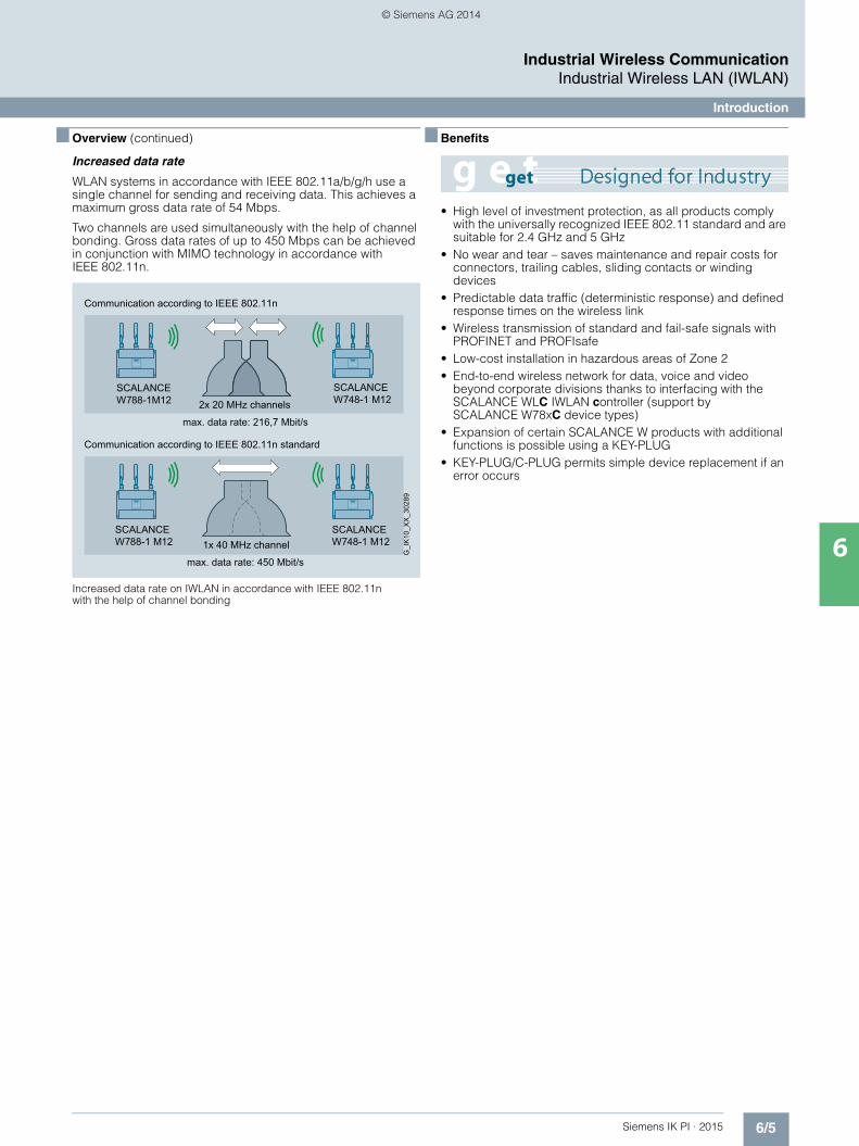
Increased data rate
WLAN systems in accordance with IEEE 802.11a/b/g/h use a single channel for sending and receiving data. This achieves a maximum gross data rate of 54 Mbps.
Two channels are used simultaneously with the help of channel bonding. Gross data rates of up to 450 Mbps can be achieved in conjunction with MIMO technology in accordance with IEEE 802.11n.
Increased data rate on IWLAN in accordance with IEEE 802.11n with the help of channel bonding
■ Benefits
• High level of investment protection, as all products comply with the universally recognized IEEE 802.11 standard and are suitable for 2.4 GHz and 5 GHz
• No wear and tear – saves maintenance and repair costs for connectors, trailing cables, sliding contacts or winding devices
• Predictable data traffic (deterministic response) and defined response times on the wireless link
• Wireless transmission of standard and fail-safe signals with PROFINET and PROFIsafe
• Low-cost installation in hazardous areas of Zone 2• End-to-end wireless network for data, voice and video
beyond corporate divisions thanks to interfacing with the SCALANCE WLC IWLAN controller (support by SCALANCE W78xC device types)
• Expansion of certain SCALANCE W products with additional functions is possible using a KEY-PLUG
• KEY-PLUG/C-PLUG permits simple device replacement if an error occurs
Communication according to IEEE 802.11n standard
Communication according to IEEE 802.11n
max. data rate: 450 Mbit/s
max. data rate: 216,7 Mbit/s
1x 40 MHz channel
2x 20 MHz channelsG
_IK
10_X
X_3
0289
SCALANCE W748-1 M12
SCALANCE W788-1M12
SCALANCE W748-1 M12
SCALANCE W788-1 M12
Kap_06_IWC_en.book Seite 5 Dienstag, 7. Oktober 2014 1:47 13
© Siemens AG 2014

6/6 Siemens IK PI · 2015
Industrial Wireless CommunicationIndustrial Wireless LAN (IWLAN)
Application examples
6
■ Overview
Wireless integration of PROFIBUS segments and PROFINET nodes into an existing Industrial Ethernet network
An existing Ethernet network can be expanded by a wireless network without increased overhead.
This even enables an existing PROFIBUS segment to be con-nected to an access point.
The wireless link is established to the mobile nodes by connect-ing a SCALANCE W access point to the Ethernet network. The mobile stations are connected wirelessly, e.g. via the SCALANCE W72x Client Module, to which the mobile station is connected with a cable.
Access to the existing controllers or processes is possible without much additional wiring.
Access Point SCALANCE W774-1 RJ45 with S7-1500 CPU
Field PG for diagnostics
Microbox 427C with SINEMA server netzwork management
Mobile Panel
Client ModuleSCALANCE
W722-1 RJ45
IE/PB LinkPN IO
ET 200SP
ET 200SP
ET 200SP
SINAMICS
IWLAN RCoax Cable
Industrial Ethernet
PROFINET
PROFIBUS
G_I
K10
_XX
_303
36
Client ModuleSCALANCE
W734-1 RJ45ET 200MP
Client ModuleSCALANCE
W722-1 RJ45
Access Point SCALANCE W788-2 M12
Access Point SCALANCE W786-1 RJ45
Kap_06_IWC_en.book Seite 6 Dienstag, 7. Oktober 2014 1:47 13
© Siemens AG 2014

6/7Siemens IK PI · 2015
6
■ Overview (continued)
Industrial Wireless CommunicationIndustrial Wireless LAN (IWLAN)
Application examples
Uninterrupted roaming between the office and automation network by using wireless LAN controllers and Industrial Wireless LAN controllers
By using the SCALANCE WLC Industrial Wireless LAN controller along with controller-based access points, it is possible to estab-lish a single wireless infrastructure for the entire company. This achieves a high level of flexibility, since mobile nodes (e.g. laptop, PDA, WLAN telephone) can move anywhere, roam-ing seamlessly between the office and automation networks. This allows wireless access to data from any location within the company. Thanks to the use of a centralized security mechanism for each user group (Virtual Network Services VNS), the data is protected against unauthorized access and manipulation.
The SCALANCE W78xC controller-based access points support the WLAN standards IEEE 802.11a/b/g and 802.11n, and they are connected via Gigabit Ethernet to the SCALANCE WLC IWLAN controller.
Operation always requires the SCALANCE WLC711 IWLAN controller that permits the configuration of access points in groups. This significantly increases the manageability of an widespread IWLAN infrastructure. Central management with the IWLAN controller also permits recording of faults/errors as well as monitoring and documentation of statistics.
Office network Plant network
Seamless roaming between office- and plant networksS7-300 with CP 343-1
Network management
S7-300 with CP 343-1
WLAN telephone
IP telephone system
IP telephoneDatabase
Smartphone
EnterasysAP3705(IEEE 802.11a/b/g)
SCALANCE W786C-2 RJ45
(IEEE 802.11a/b/g/n)
SCALANCE W788C(IEEE 802.11a/b/g/n)
EnterasysAP3710i
(IEEE 802.11a/b/g/n)
Enterasys Wireless Controller
Laptop
Router
SCALANCE W748-1 RJ45
Ethernet
Industrial Ethernet
G_I
K10
_XX
_301
75
SCALANCE WLC711 IWLAN Controller
Kap_06_IWC_en.book Seite 7 Dienstag, 7. Oktober 2014 1:47 13
© Siemens AG 2014

6/8 Siemens IK PI · 2015
6
■ Overview (continued)
Industrial Wireless CommunicationIndustrial Wireless LAN (IWLAN)
Application examples
System solution for nutrunner controls with RCoax cable and SCALANCE W788-1 RJ45
Wireless solutions with RCoax cable are typically used in the following applications:• Crane control• Overhead monorail conveyors• Storage and retrieval systems• Automated guided vehicle systems (AGVS)
An example of an application with a suspended monorail is a nutrunner controller in a car assembly plant.
An RCoax radiating cable is used along the coding rail to estab-lish wireless data transfer between the monorail and the central controller. It generates a reliable wireless field and is easy to lay.
The RCoax cable is connected as an antenna to a stationary SCALANCE W788-1 RJ45 access point with KEY-PLUG W780 i Features. This means that the same mobile unit can be used for all applications so that a mobile nutrunner can be used for several clock cycles resulting in lower investment costs.
Maintenance costs and downtimes are reduced by having reliable wireless data transmission to mobile communications partners without any wear and tear.
Downtimes are reduced because if a fault occurs, devices can be replaced without a programming device or specialist person-nel by using the KEY-PLUG/ C-PLUG swap medium.
Hangers
RCoax cableSegment 1
Nutrunnercontrol
ET 200pro
Industrial Ethernet
PROFINET
G_I
K10
_XX
_300
48
SCALANCE X208PRO
SIMATIC HMI
Access PointSCALANCEW788-1 RJ45
Client Module SCALANCE W734-1 RJ45
AntennaANT792-4DN
S7-1500
Kap_06_IWC_en.book Seite 8 Dienstag, 7. Oktober 2014 1:47 13
© Siemens AG 2014

6/9Siemens IK PI · 2015
6
■ Overview (continued)
Industrial Wireless CommunicationIndustrial Wireless LAN (IWLAN)
Application examples
Fail-safe communication with PROFIsafe – via PROFIBUS, PROFINET and even by wireless via Industrial Wireless LAN
Operation of robots in a safety-related environment
For several years, safety technology has been integrated in standard automation on the basis of SIMATIC S7 controllers, PROFIBUS and PROFIsafe.
This range has been expanded by PROFINET-compliant components, providing a complete product range with fail-safe controllers, fail-safe I/O and a corresponding engineering environment.
PROFIsafe prevents errors such as address corruption, loss, delay, etc. when transmitting messages through continuous numbering of the PROFIsafe data, time monitoring, and authen-ticity monitoring using passwords and optimized CRC backup.
This means that fail-safe communication is also supported via Industrial Wireless LAN.
Distributed l/O
Fail-safe communicationvia PROFIsafe profile
Distributed I/O
IPC427C Bundle with WinAC RTX F
Control andmonitoring system
SINUMERIK 840D sl and SINAMICS S120 Drivesother field busses
Controller
Controller
ET200 SP with SCALANCE W722
IndustrialEthernet
SINAMICS Drives
Proxy
Security
HMI
PROFIsafe
PROFIsafe
Switch
Internet
Access Point SCALANCE
W788-1 M12
SINAMICSG120
PROFINET
Safety
AS-Interface
DP/AS-i F-Link
G_I
K10
_XX
_301
18
IE/PB Link
PN IO
SCALANCE W788-2 RJ45
RCoax Cable
Effective range 1 Effective range 2 Effective range 3
IWLAN radio link
Robots Robot cell 1 Robots Robot cell 3Robots Robot cell 2
G_I
K10
_XX
_302
16
Transponder Transponder Transponder
S7-1500 F
SCALANCEX208
Mobile Panel 277F IWLAN
Industrial Ethernet
PROFINET
PROFIsafe
ET 200proET 200proET 200pro
Access PointSCALANCE W786-2IA RJ45
Access PointSCALANCE
W786-2IA RJ45
Kap_06_IWC_en.book Seite 9 Dienstag, 7. Oktober 2014 1:47 13
© Siemens AG 2014

6/10 Siemens IK PI · 2015
Industrial Wireless CommunicationIndustrial Wireless LAN (IWLAN)
Overview of network components
6
■ Overview
SCALANCE W access points, controller access points and clients and IWLAN controllers
For outdoor use
For use in control cabinet
For indoor use
* also configurable as a client module
SCALANCE WLC711
G_I
K10
_XX
_303
11
Access PointsClient Modules
W780W770W760SCALANCE
W740W730W720
Industrial Wireless LAN Controller
*
Kap_06_IWC_en.book Seite 10 Dienstag, 7. Oktober 2014 1:47 13
© Siemens AG 2014

6/11Siemens IK PI · 2015
6
■ Overview (continued)
Industrial Wireless CommunicationIndustrial Wireless LAN (IWLAN)
Overview of network components
Function overview of SCALANCE W access points according to the IEEE 802.11n standard
IEEE
802
.11n
MIM
O (I
nput
x O
utpu
t Stre
ams)
IEE
E 8
02.1
1a/ b
/ g/ h
Num
ber o
f rad
io in
terfa
ces
Inte
rnal
ant
enna
s
Con
nect
ions
for e
xter
nal a
nten
nas
(R-S
MA
)
Con
nect
ions
for e
xter
nal a
nten
nas
(N-C
onne
ct)
Qua
ntity
of L
AN
por
ts
Type
of L
AN
por
ts
PoE
(Pow
er-o
ver-
Eth
erne
t)IE
EE
802
.3at
Typ
e 1
(pre
viou
sly
802.
3af)
Red
unda
nt p
ower
sup
ply
Slo
t for
rem
ovab
le s
tora
ge (P
LUG
)
Dig
ital I
nput
Dig
ital O
utpu
t
Min
imum
ope
ratin
g te
mpe
ratu
re (°
C)
Max
imum
ope
ratin
g te
mpe
ratu
re (°
C)
IP p
rote
ctio
n cl
ass
Res
ista
nt to
con
dens
atio
n
Res
ista
nt a
gain
st s
alt s
pray
UV-
resi
stan
t
For u
se in
Ex
zone
2 w
ithou
t hou
sing
For u
se in
Ex
zone
2 1
)
Ope
ratio
n w
ith E
nter
easy
WLA
N c
ontro
ller
IWLA
N c
lient
ope
ratio
n po
ssib
leG
_IK1
0_XX
_302
80
SCALANCEW788-1 M12 3x3 ● 1 3 1 M12 ● ● ● -20 +60 65
SCALANCEW788-2 M12 3x3 ● 2 6 1 M12 ● ● ● -20 +60 65
SCALANCEW788-2 M12 EEC 3x3 ● 2 6 1 M12 ● ● ● -40 +70 65 ●
SCALANCEW788-1 RJ45 3x3 ● 1 3 1 RJ45 ● ● ● ● ● -20 +60 30
SCALANCEW788-2 RJ45 3x3 ● 2 6 1 RJ45 ● ● ● ● ● -20 +60 30
SCALANCEW786-1 RJ45 3x3 ● 1 3 1 RJ45 ● ● ● -40 +60 65 ● ● ● ● ●
SCALANCEW786-2 RJ45 3x3 ● 2 6 1 RJ45 ● ● ● -40 +60 65 ● ● ● ● ●
SCALANCEW786-2IA RJ45 3x3 ● 2 6 1 RJ45 ● ● ● -40 +60 65 ● ● ● ● ●
SCALANCEW786-2 SFP 3x3 ● 2 6 2 SFP ● -40 +60 65 ● ● ● ● ●
SCALANCEW774-1 RJ45 2x2 ● 1 2 2 RJ45 ● ● ● -20 +60 30
SCALANCEW774-1 M12 EEC 2x2 ● 1 2 2 M12 ● ● ● -20 +60 30 ●
SCALANCEW761-1 RJ45 1x1 ● 1 1 1 RJ45 0 +55 20
SCALANCEW788C-2 RJ45 3x3 ● 2 6 1 RJ45 ● ● -20 +60 30 ● ●
SCALANCEW788C-2 M12 3x3 ● 2 6 1 M12 ● ● -20 +60 65 ● ●
SCALANCEW788C-2 M12 EEC
3x3 ● 2 6 1 M12 ● ● -40 +70 65 ●
SCALANCEW786C-2 RJ45 3x3 ● 2 6 1 RJ45 ● ● -40 +60 65 ● ● ● ● ●
SCALANCEW786C-2IA RJ45 3x3 ● 2 6 1 RJ45 ● ● -40 +60 65 ● ● ● ● ●
SCALANCEW786C-2 SFP 3x3 ● 2 6 2 SFP ● -40 +60 65 ● ● ● ● ●
● suitable 1) please follow installation instructions
Kap_06_IWC_en.book Seite 11 Dienstag, 7. Oktober 2014 1:47 13
© Siemens AG 2014
6/12 Siemens IK PI · 2015
6
■ Overview (continued)
Industrial Wireless CommunicationIndustrial Wireless LAN (IWLAN)
Overview of network components
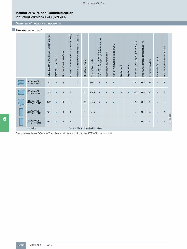
Function overview of SCALANCE W client modules according to the IEEE 802.11n standard
IEEE
802
.11n
MIM
O (I
nput
x O
utpu
t Stre
ams)
IEE
E 8
02.1
1a/ b
/ g/ h
Num
ber o
f rad
io in
terfa
ces
Con
nect
ions
for e
xter
nal a
nten
nas
(R-S
MA
)
Con
nect
ions
for e
xter
nal a
nten
nas
(N-C
onne
ct)
Qua
ntity
of L
AN p
orts
Type
of L
AN
por
ts
PoE
(Pow
er-o
ver-
Eth
erne
t)IE
EE
802
.3at
Typ
e 1
(pre
viou
sly
802.
3af)
Red
unda
nt p
ower
sup
ply
Slo
t for
rem
ovab
le s
tora
ge (P
LUG
)
Dig
ital i
nput
Dig
ital o
utpu
t
Min
imum
ope
ratin
g te
mpe
ratu
re (°
C)
Max
imum
ope
ratin
g te
mpe
ratu
re (°
C)
IP p
rote
ctio
n cl
ass
For u
se in
Ex
zone
2
Num
ber o
f con
nect
able
dev
ices
G_I
K10_
XX_3
0281
SCALANCEW748-1 M12 3x3 ● 1 3 1 M12 ● ● ● -20 +60 65 ● 8
SCALANCEW748-1 RJ45 3x3 ● 1 3 1 RJ45 ● ● ● ● ● -20 +60 30 ● 8
SCALANCEW734-1 RJ45 2x2 ● 1 2 2 RJ45 ● ● ● -20 +60 30 ● 8
SCALANCEW722-1 RJ45 1x1 ● 1 1 1 RJ4 +55 20 ● 4
SCALANCEW721-1 RJ45 1x1 ● 1 1 1 RJ4 +55 20 ● 4
● suitable 1) please follow installation instructions
Kap_06_IWC_en.book Seite 12 Dienstag, 7. Oktober 2014 1:47 13
© Siemens AG 2014
6/13Siemens IK PI · 2015
Industrial Wireless CommunicationIWLAN – Access Points IEEE 802.11n
Overview
6
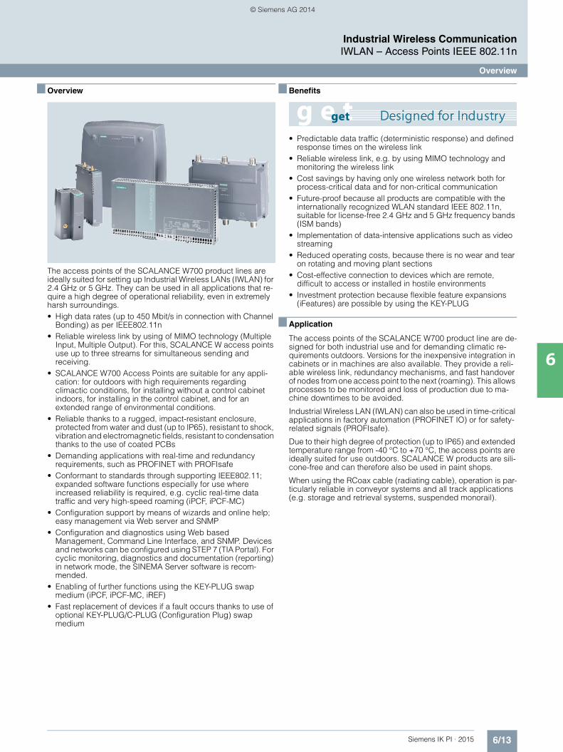
■ Overview
The access points of the SCALANCE W700 product lines are ideally suited for setting up Industrial Wireless LANs (IWLAN) for 2.4 GHz or 5 GHz. They can be used in all applications that re-quire a high degree of operational reliability, even in extremely harsh surroundings.• High data rates (up to 450 Mbit/s in connection with Channel
Bonding) as per IEEE802.11n • Reliable wireless link by using of MIMO technology (Multiple
Input, Multiple Output). For this, SCALANCE W access points use up to three streams for simultaneous sending and receiving.
• SCALANCE W700 Access Points are suitable for any appli-cation: for outdoors with high requirements regarding climactic conditions, for installing without a control cabinet indoors, for installing in the control cabinet, and for an extended range of environmental conditions.
• Reliable thanks to a rugged, impact-resistant enclosure, protected from water and dust (up to IP65), resistant to shock, vibration and electromagnetic fields, resistant to condensation thanks to the use of coated PCBs
• Demanding applications with real-time and redundancy requirements, such as PROFINET with PROFIsafe
• Conformant to standards through supporting IEEE802.11; expanded software functions especially for use where increased reliability is required, e.g. cyclic real-time data traffic and very high-speed roaming (iPCF, iPCF-MC)
• Configuration support by means of wizards and online help; easy management via Web server and SNMP
• Configuration and diagnostics using Web based Management, Command Line Interface, and SNMP. Devices and networks can be configured using STEP 7 (TIA Portal). For cyclic monitoring, diagnostics and documentation (reporting) in network mode, the SINEMA Server software is recom-mended.
• Enabling of further functions using the KEY-PLUG swap medium (iPCF, iPCF-MC, iREF)
• Fast replacement of devices if a fault occurs thanks to use of optional KEY-PLUG/C-PLUG (Configuration Plug) swap medium
■ Benefits
• Predictable data traffic (deterministic response) and defined response times on the wireless link
• Reliable wireless link, e.g. by using MIMO technology and monitoring the wireless link
• Cost savings by having only one wireless network both for process-critical data and for non-critical communication
• Future-proof because all products are compatible with the internationally recognized WLAN standard IEEE 802.11n, suitable for license-free 2.4 GHz and 5 GHz frequency bands (ISM bands)
• Implementation of data-intensive applications such as video streaming
• Reduced operating costs, because there is no wear and tear on rotating and moving plant sections
• Cost-effective connection to devices which are remote, difficult to access or installed in hostile environments
• Investment protection because flexible feature expansions (iFeatures) are possible by using the KEY-PLUG
■ Application
The access points of the SCALANCE W700 product line are de-signed for both industrial use and for demanding climatic re-quirements outdoors. Versions for the inexpensive integration in cabinets or in machines are also available. They provide a reli-able wireless link, redundancy mechanisms, and fast handover of nodes from one access point to the next (roaming). This allows processes to be monitored and loss of production due to ma-chine downtimes to be avoided.
Industrial Wireless LAN (IWLAN) can also be used in time-critical applications in factory automation (PROFINET IO) or for safety-related signals (PROFIsafe).
Due to their high degree of protection (up to IP65) and extended temperature range from -40 °C to +70 °C, the access points are ideally suited for use outdoors. SCALANCE W products are sili-cone-free and can therefore also be used in paint shops.
When using the RCoax cable (radiating cable), operation is par-ticularly reliable in conveyor systems and all track applications (e.g. storage and retrieval systems, suspended monorail).
Kap_06_IWC_en.book Seite 13 Dienstag, 7. Oktober 2014 1:47 13
© Siemens AG 2014
6/14 Siemens IK PI · 2015
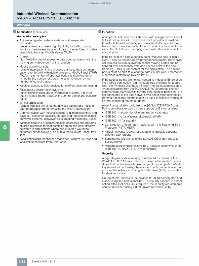
■ Application (continued)
Industrial Wireless CommunicationIWLAN – Access Points IEEE 802.11n
Overview
6
Application examples:• Automated guided vehicle systems and suspended
monorails; prevents wear and offers high flexibility for traffic routing thanks to the wireless transfer of data to the vehicles. It is also possible to transfer PROFIsafe via IWLAN.
• Cranes; high flexibility due to access to data communication with the moving unit independent of the location
• Mobile control console; reliable intervention in the process thanks to data communi-cation over IWLAN with mobile units (e.g. Mobile Panel 277(F) IWLAN); the number of operator panels is therefore deter-mined by the number of personnel and no longer by the number of control desks.
• Wireless access to field devices for configuration and testing• Passenger transportation systems;
transmission in passenger information systems, e.g. high-quality video streams between the control center and buses or trains
• Tunnel application; reliable wireless link since the devices can handle multiple path propagation better by using the MIMO technology.
• Communication with moving stations (e.g. mobile controls and devices), container logistics, storage and retrieval machines, conveyor systems, conveyor belts, rotating machines, trucks
• Wireless coupling of communication segments and bridging of large distances for fast commissioning and cost-effective networks in applications where cable routing would be extremely expensive (e.g. on public roads, rivers, lakes, train lines)
• Localization of personnel and machines using WLAN tags and localization software from AeroScout
■ Function
A simple RF field can be established with a single access point (infrastructure mode). The access point provides at least one Industrial Ethernet interface for connection to the wired network. Nodes, such as mobile controllers or a Field PG can move freely within the RF field and exchange data with other nodes via this access point.
If the RF field of a single access point (wireless cell) is insuffi-cient, it can be expanded by further access points. The individ-ual wireless cells must overlap so that moving nodes can be handed over seamlessly from one access point to the next (roaming). This is transparent for the application. The access points must be able to exchange data via Industrial Ethernet or a Wireless Distribution System (WDS).
If the access points are not connected to Industrial Ethernet us-ing a wired connection (e.g. no cable tray available for a data line), the "Wireless Distribution System" mode must be selected. An access point from the SCALANCE W700 product line can communicate via WDS with several other access points that are not connected to the data network by a direct wired connection. Remote directional antennas can be used to achieve ranges of several thousand meters outdoors.
Apart from a reliable radio link, the SCALANCE W700 Access Points are characterized by their support of IT mechanisms: • IEEE 802.11a/b/g/n for different frequency ranges • IEEE 802.11e for Wireless Multimedia (WMM)• IEEE 802.11i for security• Construction of redundant networks with the Spanning Tree
Protocols (RSTP, MSTP)• Virtual networks (VLAN) for example to logically separate
different user groups• Sending the log entries of the SCALANCE W devices to a
Syslog server• Modern security mechanisms (e.g. network security such as
IEEE 802.1x, RADIUS, EAP mechanisms)
Security
A high degree of data security is achieved by means of the WPA2/IEEE 802.11i mechanisms. These define modern proce-dures that control a regular exchange of the complete 128-bit key as well as performing the access check (authentication) of a node. The Advanced Encryption Standard (AES) is available for data encryption.
On top of this, access to the devices (HTTPS) is encrypted and a secure logon (SSH) is possible. If a security concept in combi-nation with SCALANCE S is required, the security requirements can be increased using Virtual Private Networks (VPN).
Kap_06_IWC_en.book Seite 14 Dienstag, 7. Oktober 2014 1:47 13
© Siemens AG 2014
6/15Siemens IK PI · 2015
6
■ Function (continued)
Industrial Wireless CommunicationIWLAN – Access Points IEEE 802.11n
Overview
iFeatures (only in conjunction with KEY-PLUG)
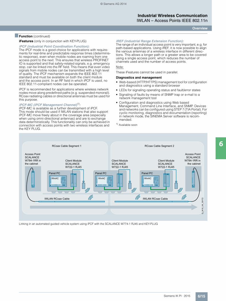
iPCF (industrial Point Coordination Function):The iPCF mode is a good choice for applications with require-ments for real-time and predictable response times (determinis-tic response), even when mobile nodes are roaming from one access point to the next. This ensures that wireless PROFINET IO is supported and that safety-related signals, e.g. emergency stop, can be linked into the RF field. This means that even video signals from mobile nodes can be transmitted with a high level of quality. The iPCF mechanism expands the IEEE 802.11 standard and must be available on both the client module and the access point. In an RF field in which iPCF is used, no IEEE 802.11-compliant nodes can be operated.
iPCF is recommended for applications where wireless network nodes move along predefined paths (e.g. suspended monorail). RCoax radiating cables or directional antennas must be used for this purpose.
iPCF-MC (iPCF Management Channel)1):iPCF-MC is available as a further development of iPCF. This mode should be used if IWLAN stations that also support iPCF-MC move freely about in the coverage area (especially when using omni-directional antennas) and are to exchange data deterministically. This functionality can only be achieved in connection with access points with two wireless interfaces and the KEY PLUG.
iREF (industrial Range Extension Function):The range of an individual access point is very important, e.g. for path-based applications. Using iREF, it is now possible to align the various antennas of a wireless interface in different direc-tions. This allows a longer path or a greater area to be covered using a single access point, which reduces the number of channels used and the number of access points.
Note:
These iFeatures cannot be used in parallel.
Diagnostics and management• Web-based (HTTP/HTTPS) management tool for configuration
and diagnostics using a standard browser• LEDs for signaling operating status and fault/error states • Signaling of faults by means of SNMP trap or e-mail to a
network management tool• Configuration and diagnostics using Web based
Management, Command Line Interface, and SNMP. Devices and networks can be configured using STEP 7 (TIA Portal). For cyclic monitoring, diagnostics and documentation (reporting) in network mode, the SINEMA Server software is recom-mended.
1) Available soon
Linking in an automated guided vehicle system using iPCF with the SCALANCE W774-1 RJ45 and KEY-PLUG
RCoax Cable Segment 1 RCoax Cable Segment 2
Access PointSCALANCE
W784-1RR inthe cabinet
Access PointSCALANCEW784-1RR inthe cabinet
G_I
K10
_XX
_301
72IWLAN RCoax Cable IWLAN RCoax Cable
Client ModuleSCALANCE W722-1 RJ45
Panel PC
Client ModuleSCALANCE W722-1 RJ45
Panel PC
Client ModuleSCALANCE W722-1 RJ45
Panel PC
WinAC WinACWinAC
Kap_06_IWC_en.book Seite 15 Dienstag, 7. Oktober 2014 1:47 13
© Siemens AG 2014
6/16 Siemens IK PI · 2015
Industrial Wireless CommunicationIWLAN – Access Points IEEE 802.11n
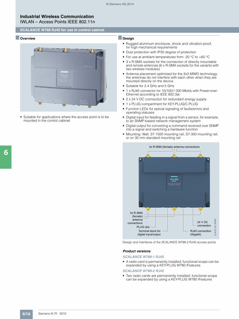
SCALANCE W788 RJ45 for use in control cabinet
6
■ Overview
• Suitable for applications where the access point is to be mounted in the control cabinet
■ Design
• Rugged aluminum enclosure, shock and vibration-proof, for high mechanical requirements
• Dust protection with IP30 degree of protection• For use at ambient temperatures from -20 °C to +60 °C• 3 x R-SMA sockets for the connection of directly mountable
and remote antennas (6 x R-SMA sockets for the variants with two wireless modules)
• Antenna placement optimized for the 3x3 MIMO technology; the antennas do not interfere with each other when they are mounted directly on the device
• Suitable for 2.4 GHz and 5 GHz• 1 x RJ45 connector for 10/100/1 000 Mbit/s with Power-over-
Ethernet according to IEEE 802.3at• 2 x 24 V DC connection for redundant energy supply• 1 x PLUG compartment for KEY-PLUG/C-PLUG• Function LEDs for optical signaling of faults/errors and
operating statuses• Digital input for feeding in a signal from a sensor, for example,
to an SNMP-based network management system• Digital output for converting a command received over SNMP
into a signal and switching a hardware function • Mounting: Wall, S7-1500 mounting rail, S7-300 mounting rail,
or on 35 mm standard mounting rail
Design and interfaces of the SCALANCE W788-2 RJ45 access points
Product versions
SCALANCE W788-1 RJ45 • A radio card is permanently installed; functional scope can be
expanded by using a KEY-PLUG W780 iFeatures
SCALANCE W788-2 RJ45 • Two radio cards are permanently installed; functional scope
can be expanded by using a KEY-PLUG W780 iFeatures
Terminal block for digital input/output
3x R-SMA (female) antenna connections
3x R-SMA (female) antenna
connections PLUG slot
24 V DC connection
RJ45 connection (Gigabit)
Kap_06_IWC_en.book Seite 16 Dienstag, 7. Oktober 2014 1:47 13
© Siemens AG 2014
6/17Siemens IK PI · 2015
Industrial Wireless CommunicationIWLAN – Access Points IEEE 802.11n
SCALANCE W788 RJ45 for use in control cabinet
6
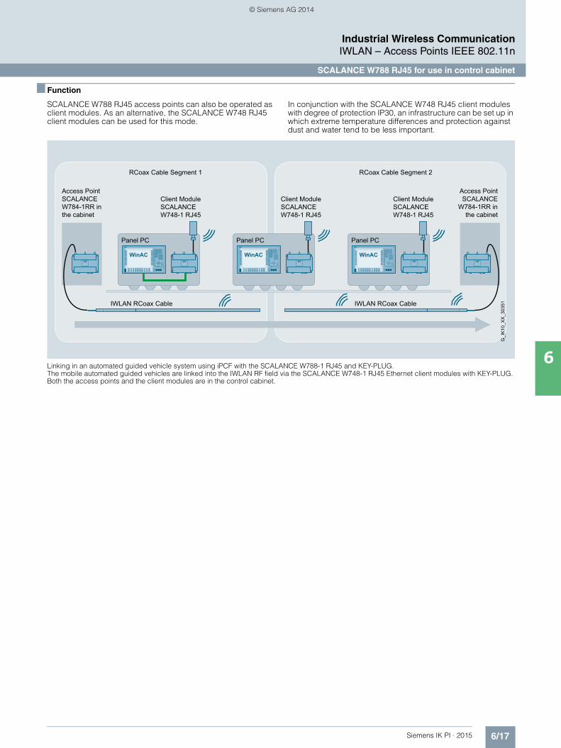
■ Function
SCALANCE W788 RJ45 access points can also be operated as client modules. As an alternative, the SCALANCE W748 RJ45 client modules can be used for this mode.
In conjunction with the SCALANCE W748 RJ45 client modules with degree of protection IP30, an infrastructure can be set up in which extreme temperature differences and protection against dust and water tend to be less important.
Linking in an automated guided vehicle system using iPCF with the SCALANCE W788-1 RJ45 and KEY-PLUG. The mobile automated guided vehicles are linked into the IWLAN RF field via the SCALANCE W748-1 RJ45 Ethernet client modules with KEY-PLUG. Both the access points and the client modules are in the control cabinet.
RCoax Cable Segment 1 RCoax Cable Segment 2
Access PointSCALANCE
W784-1RR inthe cabinet
Access PointSCALANCEW784-1RR inthe cabinet
G_I
K10
_XX
_303
51IWLAN RCoax Cable IWLAN RCoax Cable
Client ModuleSCALANCE W748-1 RJ45
Client ModuleSCALANCE W748-1 RJ45
Client ModuleSCALANCE W748-1 RJ45
Panel PC Panel PC Panel PC
Kap_06_IWC_en.book Seite 17 Dienstag, 7. Oktober 2014 1:47 13
© Siemens AG 2014

6/18 Siemens IK PI · 2015
Industrial Wireless CommunicationIWLAN – Access Points IEEE 802.11n
SCALANCE W788 RJ45 for use in control cabinet
6
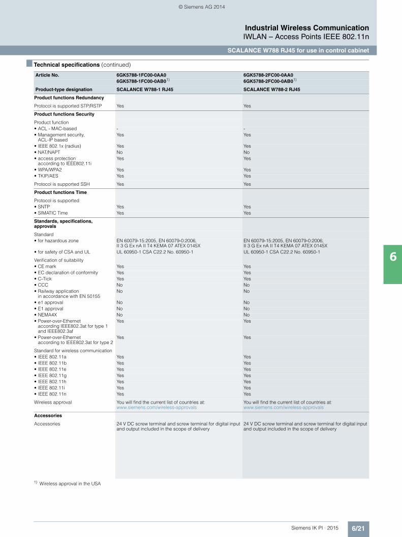
■ Technical specifications
Article No. 6GK5788-1FC00-0AA0 6GK5788-2FC00-0AA06GK5788-1FC00-0AB01) 6GK5788-2FC00-0AB01)
Product-type designation SCALANCE W788-1 RJ45 SCALANCE W788-2 RJ45
Transmission rate
Transmission rate• with W-LAN maximum 450 Mbit/s 450 Mbit/s• with Industrial Ethernet 10 … 1 000 Mbit/s 10 … 1 000 Mbit/s• note - -
Interfaces
Number of electrical connections• for network components and
terminal equipment1 1
• for power supply 1 1• for redundant power supply 1 1
Design of electrical connection• for network components and
terminal equipmentRJ45 socket RJ45 socket
• for power supply 4-pole screw terminal, PoE 4-pole screw terminal, PoE
Number of optical interfacesfor optical waveguide at 100 Mbit/s
- -
Design of optical interfacefor optical waveguide at 100 Mbit/s
- -
design of the removable storage C-PLUG
Yes Yes
Interfaces wireless
Number of radio cards permanently installed
1 2
Number of internal antennas - -
Number of electrical connectionsfor external antenna(s)
3 6
Design of the electrical connectionfor external antenna(s)
R-SMA (socket) R-SMA (socket)
Product property external antenna can be mounted directly on device
Yes Yes
Signal-Inputs/outputs
Number of digital inputs 1 1
Number of digital outputs 1 1
Design of electrical connection at the digital inputs/outputs
4-pole screw terminal 4-pole screw terminal
Signal range• at digital input 24 V DC, safety extra-low voltage 24 V DC, safety extra-low voltage• at the digital output 24 V DC /1 A 24 V DC /1 A
1) Wireless approval in the USA
Kap_06_IWC_en.book Seite 18 Dienstag, 7. Oktober 2014 1:47 13
© Siemens AG 2014

6/19Siemens IK PI · 2015
6
■ Technical specifications (continued)
Industrial Wireless CommunicationIWLAN – Access Points IEEE 802.11n
SCALANCE W788 RJ45 for use in control cabinet
Supply voltage, current consumption, power loss
Type of supply voltage DC DC
Supply voltage• 1 from terminal block 19.2 V 19.2 V• 2 from terminal block 28.8 V 28.8 V• from Power-over-Ethernet
according IEEE802.3at for type 1 and IEEE802.3af
48 V 48 V
• from Power-over-Ethernet according IEEE802.3at for type 2
50 V 50 V
Current consumed• at 24 V with DC typical 0.45 A 0.63 A• with Power-over-Ethernet
according to IEEE802.3at for type 1 and IEEE802.3af typical
0.22 A 0.22 A
• with Power-over-Ethernet according to IEEE802.3at for type 2 typical
- 0.3 A
Effective power loss• at 24V for DC typical 10.7 W 15 W• with Power-over-Ethernet
according to IEEE802.3at for type 1 and IEEE802.3af typical
- 10.7 W
• with Power-over-Ethernet according to IEEE802.3atfor type 2 typical
- 15 W
Permitted ambient conditions
Ambient temperature• during operating -20 … +60 °C -20 … +60 °C• during storage -40 … +70 °C -40 … +70 °C• during transport -40 … +70 °C -40 … +70 °C
Relative humidity at 25 °C without condensation during operating maximum
90 % 90 %
Protection class IP IP30 IP30
Ambient condition for (standard) operation mode
When used under hazardous conditions (Zone 2), the SCALANCE W788-xPRO/RR or W74x-1PRO/RR product must be installed in an enclosure. To comply with EN 50021, this enclosure must meet the requirements of at least IP 54 in compliance with EN 60529.
When used under hazardous conditions (Zone 2), the SCALANCE W788-xPRO/RR or W74x-1PRO/RR product must be installed in an enclosure. To comply with EN 50021, this enclosure must meet the requirements of at least IP 54 in compliance with EN 60529.
Design, dimensions and weight
Width of enclosure without antenna 200 mm 200 mm
Height of enclosure without antenna 158 mm 158 mm
Depth of enclosure without antenna 79 mm 79 mm
Net weight 1.7 kg 1.7 kg
Mounting type wall mounting Yes Yes
Wireless frequencies
Radio frequency• for WLAN in 2.4 GHz
frequency band2.41 … 2.48 GHz 2.41 … 2.48 GHz
• for WLAN in 5 GHzfrequency band
4.9 … 5.8 GHz 4.9 … 5.8 GHz
1) Wireless approval in the USA
Article No. 6GK5788-1FC00-0AA0 6GK5788-2FC00-0AA06GK5788-1FC00-0AB01) 6GK5788-2FC00-0AB01)
Product-type designation SCALANCE W788-1 RJ45 SCALANCE W788-2 RJ45
Kap_06_IWC_en.book Seite 19 Dienstag, 7. Oktober 2014 1:47 13
© Siemens AG 2014

6/20 Siemens IK PI · 2015
6
■ Technical specifications (continued)
Industrial Wireless CommunicationIWLAN – Access Points IEEE 802.11n
SCALANCE W788 RJ45 for use in control cabinet
Product properties, functions, components general
Product function• Access Point Mode Yes Yes• Client Mode Yes Yes
Number of SSIDs 8 16
Product function• iPCF Access Point Yes Yes• iPCF client Yes Yes• iPCF-MC Access Point in preparation in preparation• iPCF-MC client in preparation in preparation
Number of iPCF-capable radio modules
1 2
Product functions management, configuration
Number of manageable IP addresses in client
8 8
Product function• CLI Yes Yes• web-based management Yes Yes• MIB support Yes Yes• TRAPs via email Yes Yes• Configuration with STEP 7 in preparation in preparation• configuration with STEP 7
in the TIA Portalin preparation in preparation
• operation with IWLAN controller No No• operation with Enterasys WLAN
controllerNo No
• forced roaming with IWLAN Yes Yes• WDS Yes Yes
Protocol is supported• Address Resolution Protocol (ARP) Yes Yes• ICMP Yes Yes• Telnet Yes Yes• HTTP Yes Yes• HTTPS Yes Yes• TFTP Yes Yes• SNMP v1 Yes Yes• SNMP v2 Yes Yes• SNMP v3 Yes Yes• DCP Yes Yes• LLDP Yes Yes
Identification & maintenance function• I&M0 - device-specific information Yes Yes• I&M1 – higher level designation/
location designationYes Yes
Product functions Diagnosis
Product function• PROFINET IO diagnosis in preparation in preparation• localization via Aeroscout in preparation in preparation• SysLog Yes Yes
Product functions VLAN
Product function function VLAN with IWLAN
Yes Yes
Product functions DHCP
Product function• DHCP client Yes Yes• in Client Mode DHCP server via LAN No No
1) Wireless approval in the USA
Article No. 6GK5788-1FC00-0AA0 6GK5788-2FC00-0AA06GK5788-1FC00-0AB01) 6GK5788-2FC00-0AB01)
Product-type designation SCALANCE W788-1 RJ45 SCALANCE W788-2 RJ45
Kap_06_IWC_en.book Seite 20 Dienstag, 7. Oktober 2014 1:47 13
© Siemens AG 2014
6/21Siemens IK PI · 2015
6
■ Technical specifications (continued)
Industrial Wireless CommunicationIWLAN – Access Points IEEE 802.11n
SCALANCE W788 RJ45 for use in control cabinet
1) Wireless approval in the USA
Product functions Redundancy
Protocol is supported STP/RSTP Yes Yes
Product functions Security
Product function• ACL - MAC-based - -• Management security,
ACL-IP basedYes Yes
• IEEE 802.1x (radius) Yes Yes• NAT/NAPT No No• access protection
according to IEEE802.11iYes Yes
• WPA/WPA2 Yes Yes• TKIP/AES Yes Yes
Protocol is supported SSH Yes Yes
Product functions Time
Protocol is supported• SNTP Yes Yes• SIMATIC Time Yes Yes
Standards, specifications, approvals
Standard• for hazardous zone EN 60079-15:2005, EN 60079-0:2006,
II 3 G Ex nA II T4 KEMA 07 ATEX 0145XEN 60079-15:2005, EN 60079-0:2006, II 3 G Ex nA II T4 KEMA 07 ATEX 0145X
• for safety of CSA and UL UL 60950-1 CSA C22.2 No. 60950-1 UL 60950-1 CSA C22.2 No. 60950-1
Verification of suitability• CE mark Yes Yes• EC declaration of conformity Yes Yes• C-Tick Yes Yes• CCC No No• Railway application
in accordance with EN 50155No No
• e1 approval No No• E1 approval No No• NEMA4X No No• Power-over-Ethernet
according IEEE802.3at for type 1 and IEEE802.3af
Yes Yes
• Power-over-Ethernet according to IEEE802.3at for type 2
Yes Yes
Standard for wireless communication• IEEE 802.11a Yes Yes• IEEE 802.11b Yes Yes• IEEE 802.11e Yes Yes• IEEE 802.11g Yes Yes• IEEE 802.11h Yes Yes• IEEE 802.11i Yes Yes• IEEE 802.11n Yes Yes
Wireless approval You will find the current list of countries at: www.siemens.com/wireless-approvals
You will find the current list of countries at: www.siemens.com/wireless-approvals
Accessories
Accessories 24 V DC screw terminal and screw terminal for digital input and output included in the scope of delivery
24 V DC screw terminal and screw terminal for digital input and output included in the scope of delivery
Article No. 6GK5788-1FC00-0AA0 6GK5788-2FC00-0AA06GK5788-1FC00-0AB01) 6GK5788-2FC00-0AB01)
Product-type designation SCALANCE W788-1 RJ45 SCALANCE W788-2 RJ45
Kap_06_IWC_en.book Seite 21 Dienstag, 7. Oktober 2014 1:47 13
© Siemens AG 2014

6/22 Siemens IK PI · 2015
Industrial Wireless CommunicationIWLAN – Access Points IEEE 802.11n
SCALANCE W788 RJ45 for use in control cabinet
6
■ Ordering data Article No. Article No.
1) Please note national approvals under http://www.siemens.com/wireless-approvals
■ More information
Selection tools:
To assist in selecting Industrial Ethernet components, the TIA Selection Tool is available at:http://www.siemens.com/tia-selection-tool
Wireless approvals:
Current approvals can be found on the Internet at: http://www.siemens.com/wireless-approvals
SCALANCE W788 RJ45 access points
IWLAN access points with built-in wireless interfaces; wireless networks IEEE 802.11a/b/g/h/n at 2.4/5 GHz up to 450 Mbps; WPA2/AES; Power over Ethernet (PoE), IP30 degree of protection(-20 °C to +60 °C); scope of supply: Mounting hardware, 4-pin screw terminal for 24 V DC; 4-pin screw terminal for digital input and output; manual on CD-ROM; German/English
SCALANCE W788-1 RJ45
IWLAN access point with one integrated wireless interface• National approvals for operation
outside the USA6GK5788-1FC00-0AA0
• National approvals for operation within the USA1)
6GK5788-1FC00-0AB0
SCALANCE W788-2 RJ45
IWLAN dual access point with two integrated wireless interfaces• National approvals for operation
outside the USA6GK5788-2FC00-0AA0
• National approvals for operation within the USA1)
6GK5788-2FC00-0AB0
Accessories
KEY-PLUG W780 iFeatures 6GK5907-8PA00
Swap medium for enabling additional iFeatures, for simple device replacement if a fault occurs and for storage of configuration data; Can be used in SCALANCE W access points with PLUG compart-ment
C-PLUG 6GK1900-0AB00
Swap medium for simple replace-ment of devices in the event of a fault; for storing configuration data; can be used in SIMATIC NET products with PLUG compartment
DIN rail mounting adapter 6GK5798-8ML00-0AB3
DIN rail mounting adapter for SCALANCE W788 M12 and SCALANCE W788 RJ45; screw fixing for mounting on a 35 mm DIN rail to EN 50 022; scope of supply: 3 units per pack
IE FC RJ45 Plug 4 x 2
RJ45 plug-in connector for Indus-trial Ethernet (10/100/1 000 Mbps) with a rugged metal enclosure and integrated insulation displacement contacts for connecting Industrial Ethernet FC installation cables; 180° cable outlet; for network components and CPs/CPUs with Industrial Ethernet interface• 1 pack = 1 unit 6GK1901-1BB11-2AA0• 1 pack = 10 units 6GK1901-1BB11-2AB0• 1 pack = 50 units 6GK1901-1BB11-2AE0
IE FC Standard Cable GP 4x2 6XV1878-2A
8-core, shielded TP installation cable for connection to IE FC RJ45 Plug 4x2 and IE M12 Plug PRO 4x2; PROFINET-compliant; with UL approval; sold by the meter; max. length 1 000 m, minimum order 20 m
IE FC Stripping Tool 6GK1901-1GA00
Preadjusted stripping toolfor fast stripping of Industrial Ethernet FC cables
Antennas and miscellaneous IWLAN accessories
See Industrial Wireless LAN/accessories
Kap_06_IWC_en.book Seite 22 Dienstag, 7. Oktober 2014 1:47 13
© Siemens AG 2014
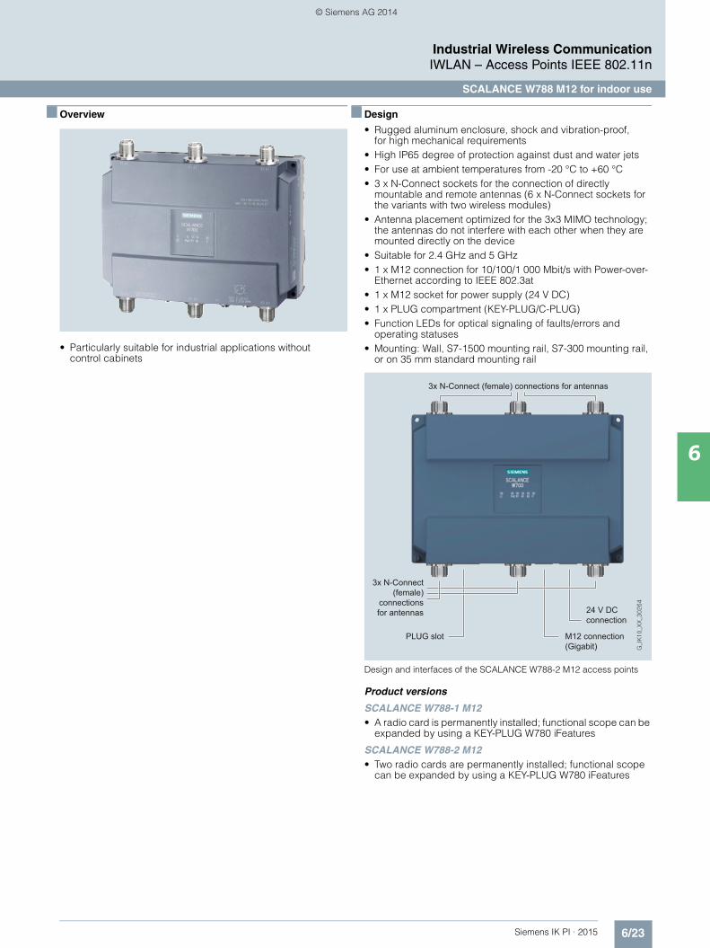
6/23Siemens IK PI · 2015
Industrial Wireless CommunicationIWLAN – Access Points IEEE 802.11n
SCALANCE W788 M12 for indoor use
6
■ Overview
• Particularly suitable for industrial applications without control cabinets
■ Design
• Rugged aluminum enclosure, shock and vibration-proof, for high mechanical requirements
• High IP65 degree of protection against dust and water jets• For use at ambient temperatures from -20 °C to +60 °C• 3 x N-Connect sockets for the connection of directly
mountable and remote antennas (6 x N-Connect sockets for the variants with two wireless modules)
• Antenna placement optimized for the 3x3 MIMO technology; the antennas do not interfere with each other when they are mounted directly on the device
• Suitable for 2.4 GHz and 5 GHz• 1 x M12 connection for 10/100/1 000 Mbit/s with Power-over-
Ethernet according to IEEE 802.3at• 1 x M12 socket for power supply (24 V DC)• 1 x PLUG compartment (KEY-PLUG/C-PLUG)• Function LEDs for optical signaling of faults/errors and
operating statuses• Mounting: Wall, S7-1500 mounting rail, S7-300 mounting rail,
or on 35 mm standard mounting rail
Design and interfaces of the SCALANCE W788-2 M12 access points
Product versions
SCALANCE W788-1 M12 • A radio card is permanently installed; functional scope can be
expanded by using a KEY-PLUG W780 iFeatures
SCALANCE W788-2 M12 • Two radio cards are permanently installed; functional scope
can be expanded by using a KEY-PLUG W780 iFeatures
3x N-Connect (female) connections for antennas
3x N-Connect (female)
connections for antennas
PLUG slot
24 V DC connection
M12 connection (Gigabit)
Kap_06_IWC_en.book Seite 23 Dienstag, 7. Oktober 2014 1:47 13
© Siemens AG 2014

6/24 Siemens IK PI · 2015
Industrial Wireless CommunicationIWLAN – Access Points IEEE 802.11n
SCALANCE W788 M12 for indoor use
6
■ Function
The devices can be installed at the location that is most favor-able for the wireless link. The enclosure and the connectors are resistant to high levels of shock and vibration because all the connectors are screwed. SCALANCE W788 M12 with degree of protection IP65 are ideally suited for environments with widely varying temperatures and where protection against dust and water play an important role. To achieve optimal coverage for
special applications, the complete range of SCALANCE W antennas is available.
SCALANCE W788-2 M12 access points can also be operated as client modules. As an alternative, the SCALANCE W748-1 M12 client modules also available with degree of protection IP65 for this mode.
Roaming devices (e.g. Field PG and mobile controller) in a wireless network with two access points
Radio cell 1 Radio cell 2
Automated Guided Vehicle System (AGVS)
G_I
K10
_XX
_302
82
Industrial Ethernet
S7-400
SIMATIC HMI
Access PointSCALANCEW788-2 M12
Access PointSCALANCEW788-2 M12
Client ModuleSCALANCE
W748-1 M12
Client ModuleSCALANCE
W748-1 M12
Client ModuleSCALANCE
W748-1 M12
Field PG/Notebook
PC PCSIMATIC HMI PCSIMATIC HMI
S7-300SCALANCE
X208 S7-300SCALANCE
X208 S7-300SCALANCE
X208
SIMATIC HMI
Kap_06_IWC_en.book Seite 24 Dienstag, 7. Oktober 2014 1:47 13
© Siemens AG 2014
6/25Siemens IK PI · 2015
Industrial Wireless CommunicationIWLAN – Access Points IEEE 802.11n
SCALANCE W788 M12 for indoor use
6
■ Technical specifications
Article No. 6GK5788-1GD00-0AA0 6GK5788-2GD00-0AA06GK5788-1GD00-0AB01) 6GK5788-2GD00-0AB01)
Product-type designation SCALANCE W788-1 M12 SCALANCE W788-2 M12
Transmission rate
Transmission rate• with W-LAN maximum 450 Mbit/s 450 Mbit/s• with Industrial Ethernet 10 … 1 000 Mbit/s 10 … 1 000 Mbit/s• note - -
Interfaces
Number of electrical connections• for network components
and terminal equipment1 1
• for power supply 1 1• for redundant power supply 1 1
Design of electrical connection• for network components
and terminal equipmentM12 interface (8-pole, A-coded) M12 interface (8-pole, A-coded)
• for power supply M12 interface (4-pole, A-coded) M12 interface (4-pole, A-coded)
Number of optical interfaces for optical waveguide at 100 Mbit/s
- -
Design of optical interface for optical waveguide at 100 Mbit/s
- -
design of the removable storage C-PLUG
Yes Yes
Interfaces wireless
Number of radio cards permanently installed
1 2
Number of internal antennas - -
Number of electrical connectionsfor external antenna(s)
3 6
Design of the electrical connectionfor external antenna(s)
N-Connect (socket) N-Connect (socket)
Product property external antenna can be mounted directly on device
Yes Yes
Supply voltage, current consumption, power loss
Type of supply voltage DC DC
Supply voltage• 1 from M12 Power Connector
(A-coded) for redundant power supply
19.2 V 19.2 V
• 2 from M12 Power Connector(A-coded) for redundant power supply
28.8 V 28.8 V
• from Power-over-Ethernetaccording IEEE802.3at for type 1 and IEEE802.3af
48 V 48 V
• from Power-over-Ethernetaccording IEEE802.3at for type 2
50 V 50 V
Current consumed• at 24 V with DC typical 0.45 A 0.63 A• with Power-over-Ethernet
according to IEEE802.3at for type 1 and IEEE802.3af typical
0.22 A 0.22 A
• with Power-over-Ethernet according to IEEE802.3atfor type 2 typical
- 0.3 A
Effective power loss• at 24V for DC typical 10.7 W 15 W• with Power-over-Ethernet
according to IEEE802.3at for type 1 and IEEE802.3af typical
- 10.7 W
• with Power-over-Ethernet according to IEEE802.3at for type 2 typical
- 15 W
1) Wireless approval in the USA
Kap_06_IWC_en.book Seite 25 Dienstag, 7. Oktober 2014 1:47 13
© Siemens AG 2014

6/26 Siemens IK PI · 2015
6
■ Technical specifications (continued)
Industrial Wireless CommunicationIWLAN – Access Points IEEE 802.11n
SCALANCE W788 M12 for indoor use
Permitted ambient conditions
Ambient temperature• during operating -20 … +60 °C -20 … +60 °C• during storage -40 … +70 °C -40 … +70 °C• during transport -40 … +70 °C -40 … +70 °C
Relative humidity at 25 °C without condensation during operating maximum
90 % 90 %
Protection class IP IP65 IP65
Ambient condition for (standard) operation mode
When used under hazardous conditions (Zone 2), the SCALANCE W788-xPRO/RR or W74x-1PRO/RR product must be installed in an enclosure. To comply with EN 50021, this enclosure must meet the requirements of at least IP 54 in compliance with EN 60529.
When used under hazardous conditions (Zone 2), the SCALANCE W788-xPRO/RR or W74x-1PRO/RR product must be installed in an enclosure. To comply with EN 50021, this enclosure must meet the requirements of at least IP 54 in compliance with EN 60529.
Design, dimensions and weight
Width of enclosure without antenna 200 mm 200 mm
Height of enclosure without antenna 176 mm 176 mm
Depth of enclosure without antenna 79 mm 79 mm
Net weight 1.7 kg 1.7 kg
Mounting type wall mounting Yes Yes
Wireless frequencies
Radio frequency• for WLAN in 2.4 GHz
frequency band2.41 … 2.48 GHz 2.41 … 2.48 GHz
• for WLAN in 5 GHz frequency band
4.9 … 5.8 GHz 4.9 … 5.8 GHz
Product properties, functions, components general
Product function• Access Point Mode Yes Yes• Client Mode Yes Yes
Number of SSIDs 8 16
Product function• iPCF Access Point Yes Yes• iPCF client Yes Yes• iPCF-MC Access Point in preparation in preparation• iPCF-MC client in preparation in preparation
Number of iPCF-capable radio modules
1 2
1) Wireless approval in the USA
Article No. 6GK5788-1GD00-0AA0 6GK5788-2GD00-0AA06GK5788-1GD00-0AB01) 6GK5788-2GD00-0AB01)
Product-type designation SCALANCE W788-1 M12 SCALANCE W788-2 M12
Kap_06_IWC_en.book Seite 26 Dienstag, 7. Oktober 2014 1:47 13
© Siemens AG 2014

6/27Siemens IK PI · 2015
6
■ Technical specifications (continued)
Industrial Wireless CommunicationIWLAN – Access Points IEEE 802.11n
SCALANCE W788 M12 for indoor use
Product functions management, configuration
Number of manageable IP addresses in client
8 8
Product function• CLI Yes Yes• web-based management Yes Yes• MIB support Yes Yes• TRAPs via email Yes Yes• Configuration with STEP 7 in preparation in preparation• configuration with STEP 7
in the TIA Portalin preparation in preparation
• operation with IWLAN controller No No• operation with Enterasys WLAN
controllerNo No
• forced roaming with IWLAN Yes Yes• WDS Yes Yes
Protocol is supported• Address Resolution Protocol (ARP) Yes Yes• ICMP Yes Yes• Telnet Yes Yes• HTTP Yes Yes• HTTPS Yes Yes• TFTP Yes Yes• SNMP v1 Yes Yes• SNMP v2 Yes Yes• SNMP v3 Yes Yes• DCP Yes Yes• LLDP Yes Yes
Identification & maintenance function• I&M0 - device-specific information Yes Yes• I&M1 – higher level designation/
location designationYes Yes
Product functions Diagnosis
Product function• PROFINET IO diagnosis in preparation in preparation• localization via Aeroscout in preparation in preparation• SysLog Yes Yes
Product functions VLAN
Product function function VLAN with IWLAN
Yes Yes
Product functions DHCP
Product function• DHCP client Yes Yes• in Client Mode DHCP server
via LANNo No
Product functions Redundancy
Protocol is supported STP/RSTP Yes Yes
1) Wireless approval in the USA
Article No. 6GK5788-1GD00-0AA0 6GK5788-2GD00-0AA06GK5788-1GD00-0AB01) 6GK5788-2GD00-0AB01)
Product-type designation SCALANCE W788-1 M12 SCALANCE W788-2 M12
Kap_06_IWC_en.book Seite 27 Dienstag, 7. Oktober 2014 1:47 13
© Siemens AG 2014
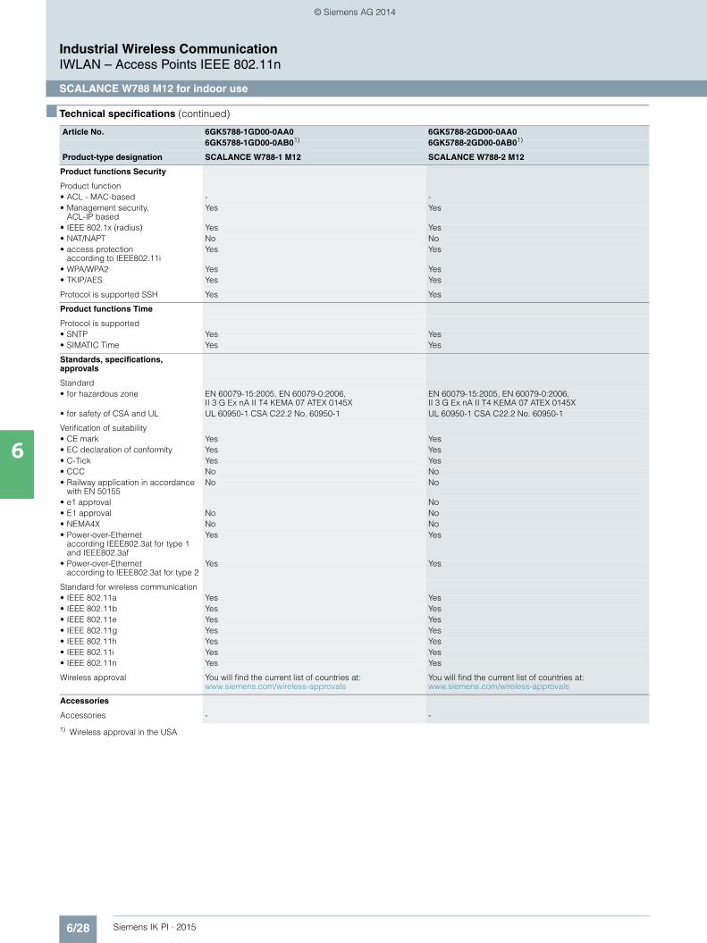
6/28 Siemens IK PI · 2015
6
■ Technical specifications (continued)
Industrial Wireless CommunicationIWLAN – Access Points IEEE 802.11n
SCALANCE W788 M12 for indoor use
1) Wireless approval in the USA
Product functions Security
Product function• ACL - MAC-based - -• Management security,
ACL-IP basedYes Yes
• IEEE 802.1x (radius) Yes Yes• NAT/NAPT No No• access protection
according to IEEE802.11iYes Yes
• WPA/WPA2 Yes Yes• TKIP/AES Yes Yes
Protocol is supported SSH Yes Yes
Product functions Time
Protocol is supported• SNTP Yes Yes• SIMATIC Time Yes Yes
Standards, specifications,approvals
Standard• for hazardous zone EN 60079-15:2005, EN 60079-0:2006,
II 3 G Ex nA II T4 KEMA 07 ATEX 0145XEN 60079-15:2005, EN 60079-0:2006, II 3 G Ex nA II T4 KEMA 07 ATEX 0145X
• for safety of CSA and UL UL 60950-1 CSA C22.2 No. 60950-1 UL 60950-1 CSA C22.2 No. 60950-1
Verification of suitability• CE mark Yes Yes• EC declaration of conformity Yes Yes• C-Tick Yes Yes• CCC No No• Railway application in accordance
with EN 50155No No
• e1 approval No• E1 approval No No• NEMA4X No No• Power-over-Ethernet
according IEEE802.3at for type 1 and IEEE802.3af
Yes Yes
• Power-over-Ethernet according to IEEE802.3at for type 2
Yes Yes
Standard for wireless communication• IEEE 802.11a Yes Yes• IEEE 802.11b Yes Yes• IEEE 802.11e Yes Yes• IEEE 802.11g Yes Yes• IEEE 802.11h Yes Yes• IEEE 802.11i Yes Yes• IEEE 802.11n Yes Yes
Wireless approval You will find the current list of countries at: www.siemens.com/wireless-approvals
You will find the current list of countries at: www.siemens.com/wireless-approvals
Accessories
Accessories - -
Article No. 6GK5788-1GD00-0AA0 6GK5788-2GD00-0AA06GK5788-1GD00-0AB01) 6GK5788-2GD00-0AB01)
Product-type designation SCALANCE W788-1 M12 SCALANCE W788-2 M12
Kap_06_IWC_en.book Seite 28 Dienstag, 7. Oktober 2014 1:47 13
© Siemens AG 2014

6/29Siemens IK PI · 2015
Industrial Wireless CommunicationIWLAN – Access Points IEEE 802.11n
SCALANCE W788 M12 for indoor use
6
■ Ordering data Article No. Article No.
1) Please note national approvals under http://www.siemens.com/wireless-approvals
■ More information
Selection tools:
To assist in selecting Industrial Ethernet components, the TIA Selection Tool is available at:http://www.siemens.com/tia-selection-tool
Wireless approvals:
Current approvals can be found on the Internet at: http://www.siemens.com/wireless-approvals
SCALANCE W788 M12 access points
IWLAN access points with built-in wireless interfaces; wireless networksIEEE 802.11a/b/g/h/n at 2.4/5 GHz up to 450 Mbit/s; WPA2/AES; Power over Ethernet (PoE),IP65 degree of protection (-20 °C to +60 °C); scope of delivery: Mounting hardware; manual on CD-ROM, German/English
SCALANCE W788-1 M12
IWLAN access point with one integrated wireless interface• National approvals for operation
outside the USA6GK5788-1GD00-0AA0
• National approvals for operation within the USA 1)
6GK5788-1GD00-0AB0
SCALANCE W788-2 M12
IWLAN dual access point with two integrated wireless interfaces• National approvals for operation
outside the USA6GK5788-2GD00-0AA0
• National approvals for operation within the USA 1)
6GK5788-2GD00-0AB0
Accessories
KEY-PLUG W780 iFeatures 6GK5907-8PA00
Swap medium for enabling addi-tional iFeatures, for simple device replacement if a fault occurs and for storage of configuration data; Can be used in SCALANCE W access points with PLUG compart-ment
C-PLUG 6GK1900-0AB00
Swap medium for simple replace-ment of devices in the event of a fault; for storing configuration data; can be used in SIMATIC NET products with PLUG compartment
DIN rail mounting adapter 6GK5798-8ML00-0AB3
DIN rail mounting adapter for SCALANCE W788 M12 and SCALANCE W788 RJ45; screw fixing for mounting on a 35 mm DIN rail to EN 50 022; scope of supply: 3 units per pack
IE FC M12 Plug PRO 4 x 2
M12 plug-in connector suitablefor on-site assembly (X-coded, IP65/IP67), metal enclosure,insulation displacement fast con-nection method, for SCALANCE W• 1 unit 6GK1901-0DB30-6AA0• 8 units 6GK1901-0DB30-6AA8
IE FC Standard Cable GP 4 x 2 6XV1878-2A
8-core, shielded TP installation cable for connection to IE FC RJ45 Plug 4 x 2 and IE M12 Plug PRO 4 x 2; PROFINET-compatible; with UL approval; sold by the meter; max. length 1 000 m, minimum order quantity 20 m
IE FC Stripping Tool 6GK1901-1GA00
Preadjusted stripping tool for fast stripping of the Industrial Ethernet FC cables
Power M12 Cable Connector PRO 6GK1907-0DC10-6AA3
Terminal socket for connection of SCALANCE W700 for 24 V DC supply voltage; 4-pole, A-coded, with assembly instructions, 3 units
Power Cable 2 x 0.75 6XV1812-8A
Connecting cable for Power M12 Cable Connector PRO, sold by the meter
Antennas and miscellaneous IWLAN accessories
See Industrial Wireless LAN/accessories
Kap_06_IWC_en.book Seite 29 Dienstag, 7. Oktober 2014 1:47 13
© Siemens AG 2014
6/30 Siemens IK PI · 2015
Industrial Wireless CommunicationIWLAN – Access Points IEEE 802.11n
SCALANCE W788 M12 EEC for enhanced environmental conditions
6
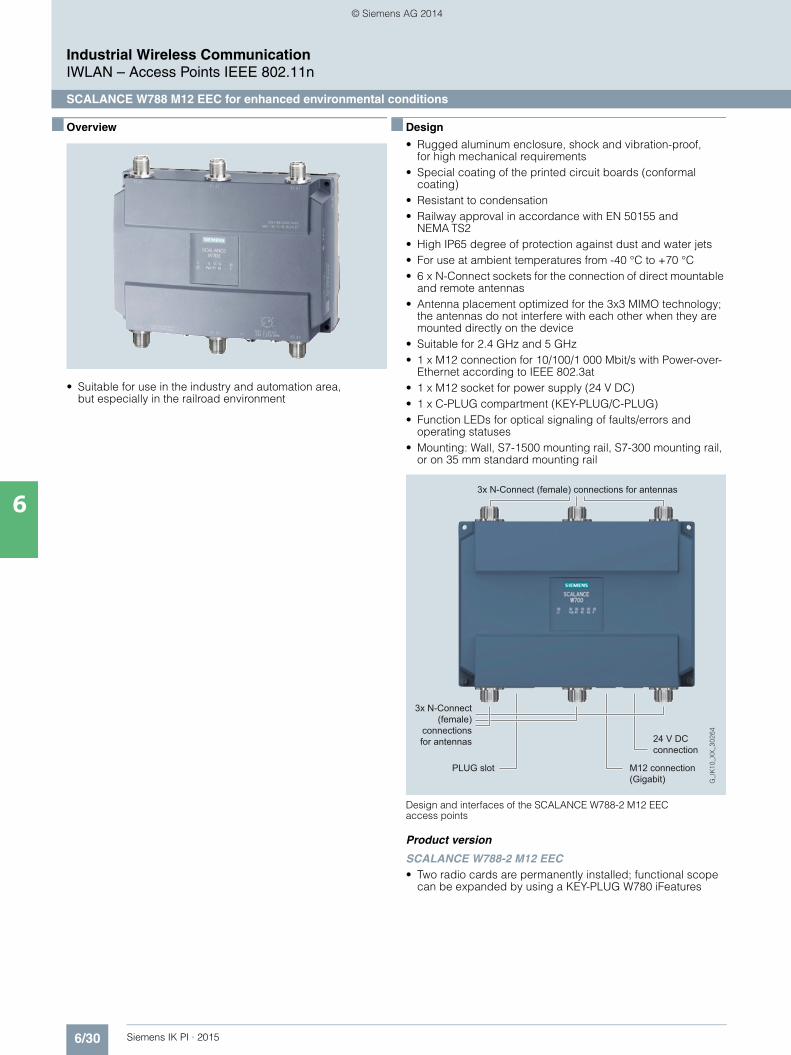
■ Overview
• Suitable for use in the industry and automation area, but especially in the railroad environment
■ Design
• Rugged aluminum enclosure, shock and vibration-proof, for high mechanical requirements
• Special coating of the printed circuit boards (conformal coating)
• Resistant to condensation• Railway approval in accordance with EN 50155 and
NEMA TS2• High IP65 degree of protection against dust and water jets• For use at ambient temperatures from -40 °C to +70 °C• 6 x N-Connect sockets for the connection of direct mountable
and remote antennas • Antenna placement optimized for the 3x3 MIMO technology;
the antennas do not interfere with each other when they are mounted directly on the device
• Suitable for 2.4 GHz and 5 GHz• 1 x M12 connection for 10/100/1 000 Mbit/s with Power-over-
Ethernet according to IEEE 802.3at• 1 x M12 socket for power supply (24 V DC)• 1 x C-PLUG compartment (KEY-PLUG/C-PLUG)• Function LEDs for optical signaling of faults/errors and
operating statuses• Mounting: Wall, S7-1500 mounting rail, S7-300 mounting rail,
or on 35 mm standard mounting rail
Design and interfaces of the SCALANCE W788-2 M12 EEC access points
Product version
SCALANCE W788-2 M12 EEC• Two radio cards are permanently installed; functional scope
can be expanded by using a KEY-PLUG W780 iFeatures
3x N-Connect (female) connections for antennas
3x N-Connect (female)
connections for antennas
PLUG slot
24 V DC connection
M12 connection (Gigabit)
Kap_06_IWC_en.book Seite 30 Dienstag, 7. Oktober 2014 1:47 13
© Siemens AG 2014

6/31Siemens IK PI · 2015
Industrial Wireless CommunicationIWLAN – Access Points IEEE 802.11n
SCALANCE W788 M12 EEC for enhanced environmental conditions
6
■ Function
The SCALANCE W788 M12 EEC (Extended Environmental Conditions) are designed for use in railway applications. The de-vices satisfy EN 50155, the approval for railway applications, and can thus be used for rail traffic. The devices also have an extended temperature range from -40 °C to +70 °C. Combined with the railway-approved antennas, which are connected via the N-Connect antenna connections (female), these products can establish a reliable IWLAN wireless infrastructure outdoors.
The devices can be installed at the location that is most favorable for the wireless link. The enclosure and the connectors are resistant to high levels of shock and vibration because all the connectors are screwed. Thanks to Conformal Coating and IP65 degree of protection, SCALANCE W788 M12 EEC is ideally suited for environments with widely varying temperatures and where protection against dust and water play an important role. To achieve optimal coverage for special applications, the complete range of SCALANCE W antennas is available. Some antennas even have railway certification.
SCALANCE W788-2 M12 EEC access points can also be operated as client modules.
Data transmission on trains using the SCALANCE W788 M12 EEC access points with railway certification
Provided that a delay (several 100 ms) caused by roaming in accordance with IEEE 802.11 is tolerated by all communication stations when switching the radio cells, the communication continues uninterrupted.
For real-time requirements, the SCALANCE W788 M12 EEC can be equipped with KEY-PLUG functionality for activating iFeatures.
SCALANCE XR324-12M TS
with M12 module
SCALANCE W788-2 M12 EEC
TunnelTunnel
SCALANCE W788-2 M12 EEC
Tunnel
G_I
K10_
XX
_303
07
Industrial Ethernet (Trainside)
SCALANCE W788-2 M12 EEC
SCALANCE W788-2 M12
EEC
Workstations
Infotainment Server
SCALANCE X308-2M TS
SCALANCE XR552-12M
Industrial Ethernet (Trackside)
SCALANCE W788-2 M12
EEC
TrainguardTrain Control
Communication Server
Content Workstation
Industrial Ethernet (Trainside)
ANT 795-6MN
ANT 795-6MN
ANT793-8DJ ANT793-8DJ ANT793-8DJ ANT793-8DJ
Kap_06_IWC_en.book Seite 31 Dienstag, 7. Oktober 2014 1:47 13
© Siemens AG 2014

6/32 Siemens IK PI · 2015
Industrial Wireless CommunicationIWLAN – Access Points IEEE 802.11n
SCALANCE W788 M12 EEC for enhanced environmental conditions
6
■ Technical specifications
Article No. 6GK5788-2GD00-0TA06GK5788-2GD00-0TB01)
Product-type designation SCALANCE W788-2 M12 EEC
Transmission rate
Transmission rate• with W-LAN maximum 450 Mbit/s• with Industrial Ethernet 10 … 1 000 Mbit/s• note -
Interfaces
Number of electrical connections• for network components
and terminal equipment1
• for power supply 1• for redundant power supply 1
Design of the electrical connection• for network components
and terminal equipmentM12 interface (8-pole, X-coded), PoE
• for power supply M12 interface (4-pole, A-coded)
Number of optical interfaces for optical waveguide at 100 Mbit/s
-
Design of optical interfacefor optical waveguide at 100 Mbit/s
-
Design of the removable storage C-PLUG
Yes
Interfaces wireless
Number of radio cards permanently installed
2
Number of internal antennas -
Number of electrical connectionsfor external antenna(s)
6
Design of the electrical connectionfor external antenna(s)
N-Connect (socket)
Product property external antenna can be mounted directly on device
Yes
Supply voltage,current consumption, power loss
Type of supply voltage DC
Supply voltage• 1 from M12 Power Connector
(A-coded) for redundant power supply
19.2 V
• 2 from M12 Power Connector(A-coded) for redundant power supply
28.8 V
• from Power-over-Ethernetaccording IEEE802.3at for type 1 and IEEE802.3af
48 V
• from Power-over-Ethernet according IEEE802.3at for type 2
50 V
Current consumed• at 24 V with DC typical 0.63 A• with Power-over-Ethernet
according to IEEE802.3at for type 1 and IEEE802.3af typical
0.22 A
• with Power-over-Ethernet according to IEEE802.3at for type 2 typical
0.3 A
Effective power loss• at 24V for DC typical 15 W• with Power-over-Ethernet
according to IEEE802.3at for type 1 and IEEE802.3af typical
10.7 W
• with Power-over-Ethernet according to IEEE802.3at for type 2 typical
15 W
Permitted ambient conditions
Ambient temperature• during operating -20 … +60 °C• during storage -40 … +70 °C• during transport -40 … +70 °C
Relative humidity at 25 °C without condensation during operating maximum
90 %
Protection class IP IP65
Ambient condition for (standard) operation mode
When used under hazardous conditions (Zone 2), the SCALANCE W788-xPRO/RR or W74x-1PRO/RR product must be installed in an enclosure. To comply with EN 50021, this enclosure must meet the requirements of at least IP54 in compliance with EN 60529.
Design, dimensions and weight
Width of enclosure without antenna 200 mm
Height of enclosure without antenna 176 mm
Depth of enclosure without antenna 79 mm
Net weight 1.7 kg
Mounting type wall mounting Yes
Wireless frequencies
Radio frequency• for WLAN in 2.4 GHz
frequency band2.41 … 2.48 GHz
• for WLAN in 5 GHzfrequency band
4.9 … 5.8 GHz
Product properties, functions, components general
Product function• Access Point Mode Yes• Client Mode Yes
Number of SSIDs 16
Product function• iPCF Access Point Yes• iPCF client Yes• iPCF-MC Access Point in preparation• iPCF-MC client in preparation
Number of iPCF-capable radio modules
0
Article No. 6GK5788-2GD00-0TA06GK5788-2GD00-0TB01)
Product-type designation SCALANCE W788-2 M12 EEC
Kap_06_IWC_en.book Seite 32 Dienstag, 7. Oktober 2014 1:47 13
© Siemens AG 2014

6/33Siemens IK PI · 2015
6
■ Technical specifications (continued)
Industrial Wireless CommunicationIWLAN – Access Points IEEE 802.11n
SCALANCE W788 M12 EEC for enhanced environmental conditions
1) Wireless approval in the USA
Product functions management, configuration
Number of manageableIP addresses in client
8
Product function• CLI Yes• web-based management Yes• MIB support Yes• TRAPs via email Yes• Configuration with STEP 7 in preparation• configuration with STEP 7
in the TIA Portalin preparation
• operation with IWLAN controller No• operation with Enterasys WLAN
controllerNo
• forced roaming with IWLAN Yes• WDS Yes
Protocol is supported• Address Resolution Protocol (ARP) Yes• ICMP Yes• Telnet Yes• HTTP Yes• HTTPS Yes• TFTP Yes• SNMP v1 Yes• SNMP v2 Yes• SNMP v3 Yes• DCP Yes• LLDP Yes
Identification & maintenance function• I&M0 - device-specific information Yes• I&M1 – higher level designation/
location designationYes
Product functions Diagnosis
Product function• PROFINET IO diagnosis in preparation• localization via Aeroscout in preparation• SysLog Yes
Product functions VLAN
Product function function VLAN with IWLAN
Yes
Product functions DHCP
Product function• DHCP client Yes• in Client Mode DHCP server
via LANNo
Product functions Redundancy
Protocol is supported STP/RSTP Yes
Article No. 6GK5788-2GD00-0TA06GK5788-2GD00-0TB01)
Product-type designation SCALANCE W788-2 M12 EEC
Product functions Security
Product function• ACL - MAC-based -• Management security,
ACL-IP basedYes
• IEEE 802.1x (radius) Yes• NAT/NAPT No• access protection
according to IEEE802.11iYes
• WPA/WPA2 Yes• TKIP/AES Yes
Protocol is supported SSH Yes
Product functions Time
Protocol is supported• SNTP Yes• SIMATIC Time Yes
Standards, specifications, approvals
Standard• for hazardous zone -• for safety of CSA and UL UL 60950-1 CSA C22.2 No. 60950-1
Verification of suitability• CE mark Yes• EC declaration of conformity Yes• C-Tick Yes• CCC -• Railway application
in accordance with EN 50155Yes
• e1 approval No• E1 approval No• NEMA4X No• Power-over-Ethernet
according IEEE802.3at for type 1 and IEEE802.3af
Yes
• Power-over-Ethernet according to IEEE802.3at for type 2
Yes
Standard for wireless communication• IEEE 802.11a Yes• IEEE 802.11b Yes• IEEE 802.11e Yes• IEEE 802.11g Yes• IEEE 802.11h Yes• IEEE 802.11i Yes• IEEE 802.11n Yes
Wireless approval You will find the current list of countries at: www.siemens.com/wireless-approvals
Article No. 6GK5788-2GD00-0TA06GK5788-2GD00-0TB01)
Product-type designation SCALANCE W788-2 M12 EEC
Kap_06_IWC_en.book Seite 33 Dienstag, 7. Oktober 2014 1:47 13
© Siemens AG 2014

6/34 Siemens IK PI · 2015
Industrial Wireless CommunicationIWLAN – Access Points IEEE 802.11n
SCALANCE W788 M12 EEC for enhanced environmental conditions
6
■ Ordering data Article No. Article No.
1) Please note national approvals underhttp://www.siemens.com/wireless-approvals
■ More information
Selection tools:
To assist in selecting Industrial Ethernet components, the TIA Selection Tool is available at:http://www.siemens.com/tia-selection-tool
Wireless approvals:
Current approvals can be found on the Internet at: http://www.siemens.com/wireless-approvals
SCALANCE W788 M12 EEC access points
IWLAN access points with built-in wireless interfaces; wireless networks IEEE 802.11a/b/g/h/n at 2.4/5 GHz up to 450 Mbit/s; railway approval in accordance with EN 50155 / NEMA TS2;conformal coating; WPA2/AES; Power over Ethernet (PoE), IP65 degree of protection; scope of supply: Mounting hardware; manual on CD-ROM, German/English
SCALANCE W788-2 M12 EEC
IWLAN dual access point with two integrated wireless interfaces• National approvals for operation
outside the USA6GK5788-2GD00-0TA0
• National approvals for operation within the USA 1)
6GK5788-2GD00-0TB0
Accessories
KEY-PLUG W780 iFeatures 6GK5907-8PA00
Swap medium for enabling addi-tional iFeatures, for simple device replacement if a fault occurs and for storage of configuration data; Can be used in SCALANCE W access points with PLUG compart-ment
C-PLUG 6GK1900-0AB00
Swap medium for simple replace-ment of devices in the event of a fault;for storing configuration data;can be used in SIMATIC NET prod-ucts with PLUG compartment
DIN rail mounting adapter 6GK5798-8ML00-0AB3
DIN rail mounting adapter for SCALANCE W788 M12 and SCALANCE W788 RJ45; screw fixing for mounting on a 35 mm DIN rail to EN 50 022; scope of supply: 3 units per pack
IE FC M12 Plug PRO 4 x 2
M12 plug-in connector suitablefor on-site assembly (X-coded, IP65/IP67), metal enclosure,insulation displacement fast con-nection method, for SCALANCE W• 1 unit 6GK1901-0DB30-6AA0• 8 units 6GK1901-0DB30-6AA8
IE FC Standard Cable GP 4 x 2 6XV1878-2A
8-core, shielded TP installation cable for connection to IE FC RJ45 Plug 4 x 2 and IE M12 Plug PRO 4 x 2; PROFINET-compatible; with UL approval; sold by the meter; max. length 1 000 m, minimum order quantity 20 m
IE FC Stripping Tool 6GK1901-1GA00
Preadjusted stripping tool for fast stripping of the Industrial Ethernet FC cables
Power M12 Cable Connector PRO 6GK1907-0DC10-6AA3
Terminal socket for connection of SCALANCE W700 for 24 V DC supply voltage; 4-pole, A-coded, with assembly instructions, 3 units
Power Cable 2 x 0.75 6XV1812-8A
Connecting cable for Power M12 Cable Connector PRO, sold by the meter
Antennas and miscellaneous IWLAN accessories
See Industrial Wireless LAN/accessories
Kap_06_IWC_en.book Seite 34 Dienstag, 7. Oktober 2014 1:47 13
© Siemens AG 2014
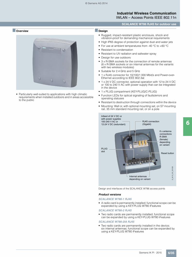
6/35Siemens IK PI · 2015
Industrial Wireless CommunicationIWLAN – Access Points IEEE 802.11n
SCALANCE W786 RJ45 for outdoor use
6
■ Overview
• Particularly well-suited to applications with high climatic requirements when installed outdoors and in areas accessible to the public
■ Design
• Rugged, impact-resistant plastic enclosure, shock and vibration-proof for demanding mechanical requirements
• High IP65 degree of protection against dust and water jets• For use at ambient temperatures from -40 °C to +60 °C• Resistant to condensation • Resistant to UV radiation and saltwater spray• Design for use outdoors• 3 x R-SMA sockets for the connection of remote antennas
(6 x R-SMA sockets or six internal antennas for the variants with two wireless modules)
• Suitable for 2.4 GHz and 5 GHz• 1 x RJ45 connector for 10/100/1 000 Mbit/s and Power-over-
Ethernet according to IEEE 802.3at • 1 x 24 V DC connector, optional operation with 12 to 24 V DC
or 100 to 240 V AC with power supply that can be integrated in the device
• 1 x PLUG compartment (KEY-PLUG/C-PLUG)• Function LEDs for optical signaling of faults/errors and
operating statuses• Resistant to destruction through connections within the device• Mounting: Wall or, with optional mounting set, on S7 mounting
rail, 35 mm standard mounting rail, or on a pole
Design and interfaces of the SCALANCE W786 access points
Product versions
SCALANCE W786-1 RJ45 • A radio card is permanently installed; functional scope can be
expanded by using a KEY-PLUG W780 iFeatures
SCALANCE W786-2 RJ45 • Two radio cards are permanently installed; functional scope
can be expanded by using a KEY-PLUG W780 iFeatures
SCALANCE W786-2IA RJ45 • Two radio cards are permanently installed in the device;
six internal antennas; functional scope can be expanded by using a KEY-PLUG W780 iFeatures
Infeed of 24 V DC or with power supplies 100-240 V AC or12-24 V DC (redundant)
PLUG slot
Reset button
Internal antennas depending on variant
6 x antennaconnections R-SMA (female) dependingon variant
RJ45 connection (Gigabit)
Kap_06_IWC_en.book Seite 35 Dienstag, 7. Oktober 2014 1:47 13
© Siemens AG 2014

6/36 Siemens IK PI · 2015
Industrial Wireless CommunicationIWLAN – Access Points IEEE 802.11n
SCALANCE W786 RJ45 for outdoor use
6
■ Function
In the case of access points with two wireless modules, one module implements communication of the access points with each other. The radio link for the stations, e.g. a mobile crane system, is established by the second wireless module. Wireless coverage of larger areas can therefore be provided with the same device.
In the case of SCALANCE W786, this only concerns access points which can, however, be configured as client modules through Web-based management. Then, depending on the selected variant, a maximum of one radio module will be avail-able as a client.
Use of the SCALANCE W786 product line in areas subject to demanding climatic requirements
AntennaANT793-8DJ
AntennaANT793-6DG
Radio cell
SCALANCE W786-1 RJ45
SCALANCE W786-1 RJ45
Kap_06_IWC_en.book Seite 36 Dienstag, 7. Oktober 2014 1:47 13
© Siemens AG 2014

6/37Siemens IK PI · 2015
Industrial Wireless CommunicationIWLAN – Access Points IEEE 802.11n
SCALANCE W786 RJ45 for outdoor use
6
■ Technical specifications
Article No. 6GK5786-1FC00-0AA0 6GK5786-2HC00-0AA0 6GK5786-2FC00-0AA06GK5786-1FC00-0AB01) 6GK5786-2HC00-0AB01) 6GK5786-2FC00-0AB01)
Product-type designation SCALANCE W786-1 RJ45 SCALANCE W786-2IA RJ45 SCALANCE W786-2 RJ45
Transmission rate
Transmission rate• with W-LAN maximum 450 Mbit/s 450 Mbit/s 450 Mbit/s• with Industrial Ethernet 10 … 1 000 Mbit/s 10 … 1 000 Mbit/s 10 … 1 000 Mbit/s• note - - -
Interfaces
Number of electrical connections• for network components
and terminal equipment1 1 1
• for power supply 1 1 1• for redundant power supply 1 1 1
Design of electrical connection• for network components
and terminal equipmentRJ45 socket RJ45 socket RJ45 socket
• for power supply 2-pole connector (24 V DC) or optionally available power supply adapter (4-pole 24 V DC or 3-pole 110 to 230 V AC)
2-pole connector (24 V DC) or optionally available power supply adapter (4-pole 24 V DC or 3-pole 110 to 230 V AC)
2-pole connector (24 V DC) or optionally available power supply adapter (4-pole 24 V DC or 3-pole 110 to 230 V AC)
Number of optical interfaces for optical waveguide at 100 Mbit/s
- - -
Design of optical interfacefor optical waveguide at 100 Mbit/s
- - -
Number of optical interfacesfor optical waveguide at 1 000 Mbit/s
- - -
Design of optical interfacefor optical waveguide at 1 000 Mbit/s
- - -
design of the removable storage C-PLUG
Yes Yes Yes
Interfaces wireless
Number of radio cards permanently installed
1 2 2
Number of internal antennas - 6 -
Number of electrical connectionsfor external antenna(s)
3 - 6
Design of the electrical connectionfor external antenna(s)
R-SMA (socket) - R-SMA (socket)
Product property external antenna can be mounted directly on device
No - No
1) Wireless approval in the USA
Kap_06_IWC_en.book Seite 37 Dienstag, 7. Oktober 2014 1:47 13
© Siemens AG 2014

6/38 Siemens IK PI · 2015
6
■ Technical specifications (continued)
Industrial Wireless CommunicationIWLAN – Access Points IEEE 802.11n
SCALANCE W786 RJ45 for outdoor use
Supply voltage, current consumption, power loss
Type of supply voltage DC DC DC
Supply voltage• 1 from terminal block 19.2 V 19.2 V 19.2 V• 2 from terminal block 28.8 V 28.8 V 28.8 V• from Power-over-Ethernet
according IEEE802.3at for type 1 and IEEE802.3af
48 V 48 V 48 V
• from Power-over-Ethernetaccording IEEE802.3at for type 2
50 V 50 V 50 V
• from optional integratable power supply- with AC 100 … 240 V 100 … 240 V 100 … 240 V- with DC 12 … 24 V 12 … 24 V 12 … 24 V
Current consumed• at 24 V with DC typical 0.45 A 0.63 A 0.63 A• at 230 V with AC typical 0.05 A 0.07 A 0.07 A• with Power-over-Ethernet
according to IEEE802.3at for type 1 and IEEE802.3af typical
0.22 A 0.22 A 0.22 A
• with Power-over-Ethernet according to IEEE802.3at for type 2 typical
- - -
Effective power loss• at 24V for DC typical 10.7 W 15 W 15 W• at 230 V with AC typical 10.7 W 15 W 15 W• with Power-over-Ethernet
according to IEEE802.3at for type 1 and IEEE802.3af typical
10.7 W 15 W 10.7 W
• with Power-over-Ethernet according to IEEE802.3at for type 2 typical
- - -
Permitted ambient conditions
Ambient temperature• during operating -40 … +60 °C -40 … +60 °C -40 … +60 °C• during storage -40 … +85 °C -40 … +85 °C -40 … +85 °C• during transport -40 … +85 °C -40 … +85 °C -40 … +85 °C
Relative humidity at 25 °C without condensation during operating maximum
100 % 100 % 100 %
Protection class IP IP65 IP65 IP65
Ambient condition for (standard) operation mode
When using the power supply100 to 240 V AC, an operating temperature of-40 °C to +60 °C is permissible
When using the power supply 100 to 240 V AC, an operating temperature of -40 °C to +60 °C is permissible
When using the power supply 100 to 240 V AC, an operating temperature of -40 °C to +60 °C is permissible
Design, dimensions and weight
Width of enclosure without antenna 251 mm 251 mm 251 mm
Height of enclosure without antenna 251 mm 251 mm 251 mm
Depth of enclosure without antenna 72 mm 72 mm 72 mm
Net weight 2.24 kg 2.24 kg 2.24 kg
Mounting type wall mounting Yes Yes Yes
Mounting type For mast mounting,35 mm DIN rail mounting and S7-300 rail mounting, an additional support plate is required
For mast mounting, 35 mm DIN rail mounting and S7-300 rail mounting, an additional support plate is required
For mast mounting, 35 mm DIN rail mounting and S7-300 rail mounting, an additional support plate is required
Wireless frequencies
Radio frequency• for WLAN in 2.4 GHz
frequency band2.41 … 2.48 GHz 2.41 … 2.48 GHz 2.41 … 2.48 GHz
• for WLAN in 5 GHzfrequency band
4.9 … 5.8 GHz 4.9 … 5.8 GHz 4.9 … 5.8 GHz
1) Wireless approval in the USA
Article No. 6GK5786-1FC00-0AA0 6GK5786-2HC00-0AA0 6GK5786-2FC00-0AA06GK5786-1FC00-0AB01) 6GK5786-2HC00-0AB01) 6GK5786-2FC00-0AB01)
Product-type designation SCALANCE W786-1 RJ45 SCALANCE W786-2IA RJ45 SCALANCE W786-2 RJ45
Kap_06_IWC_en.book Seite 38 Dienstag, 7. Oktober 2014 1:47 13
© Siemens AG 2014

6/39Siemens IK PI · 2015
6
■ Technical specifications (continued)
Industrial Wireless CommunicationIWLAN – Access Points IEEE 802.11n
SCALANCE W786 RJ45 for outdoor use
Product properties, functions, components general
Product function• Access Point Mode Yes Yes Yes• Client Mode Yes Yes Yes
Number of SSIDs 8 16 16
Product function• iPCF Access Point Yes Yes Yes• iPCF client Yes Yes Yes• iPCF-MC Access Point in preparation in preparation in preparation• iPCF-MC client in preparation in preparation in preparation
Number of iPCF-capable radio modules
1 2 2
Product functions management, configuration
Number of manageable IP addresses in client
8 8 8
Product function• CLI Yes Yes Yes• web-based management Yes Yes Yes• MIB support Yes Yes Yes• TRAPs via email Yes Yes Yes• Configuration with STEP 7 in preparation in preparation in preparation• configuration with STEP 7
in the TIA Portalin preparation in preparation in preparation
• operation with IWLAN controller No No No• operation with Enterasys WLAN
controllerNo No No
• forced roaming with IWLAN Yes Yes Yes• WDS Yes Yes Yes
Protocol is supported• Address Resolution Protocol (ARP) Yes Yes Yes• ICMP Yes Yes Yes• Telnet Yes Yes Yes• HTTP Yes Yes Yes• HTTPS Yes Yes Yes• TFTP Yes Yes Yes• SNMP v1 Yes Yes Yes• SNMP v2 Yes Yes Yes• SNMP v3 Yes Yes Yes• DCP Yes Yes Yes• LLDP Yes Yes Yes
Identification & maintenance function• I&M0 - device-specific information Yes Yes Yes• I&M1 – higher level designation/
location designationYes Yes Yes
Product functions Diagnosis
Product function• PROFINET IO diagnosis in preparation in preparation in preparation• localization via Aeroscout in preparation in preparation in preparation• SysLog Yes Yes Yes
Product functions VLAN
Product function function VLAN with IWLAN
Yes Yes Yes
Product functions DHCP
Product function• DHCP client Yes Yes Yes• in Client Mode DHCP server
via LANNo No No
1) Wireless approval in the USA
Article No. 6GK5786-1FC00-0AA0 6GK5786-2HC00-0AA0 6GK5786-2FC00-0AA06GK5786-1FC00-0AB01) 6GK5786-2HC00-0AB01) 6GK5786-2FC00-0AB01)
Product-type designation SCALANCE W786-1 RJ45 SCALANCE W786-2IA RJ45 SCALANCE W786-2 RJ45
Kap_06_IWC_en.book Seite 39 Dienstag, 7. Oktober 2014 1:47 13
© Siemens AG 2014

6/40 Siemens IK PI · 2015
6
■ Technical specifications (continued)
Industrial Wireless CommunicationIWLAN – Access Points IEEE 802.11n
SCALANCE W786 RJ45 for outdoor use
1) Wireless approval in the USA
Product functions Redundancy
Protocol is supported STP/RSTP Yes Yes Yes
Product functions Security
Product function• ACL - MAC-based - - -• Management security,
ACL-IP based- Yes Yes
• IEEE 802.1x (radius) Yes Yes Yes• NAT/NAPT No No No• access protection
according to IEEE802.11iYes Yes Yes
• WPA/WPA2 Yes Yes Yes• TKIP/AES Yes Yes Yes
Protocol is supported SSH Yes Yes Yes
Product functions Time
Protocol is supported• SNTP Yes Yes Yes• SIMATIC Time Yes Yes Yes
Standards, specifications, approvals
Standard• for EMC from FM - - -• for hazardous zone EN 60079-15:2005, EN 60079-0:2006,
II 3 G Ex nA II T4 KEMA 07 ATEX 0145XEN 60079-15:2005, EN 60079-0:2006, II 3 G Ex nA II T4 KEMA 07 ATEX 0145X
EN 60079-15:2005, EN 60079-0:2006, II 3 G Ex nA II T4 KEMA 07 ATEX 0145X
• for safety of CSA and UL UL 60950-1 CSA C22.2 No. 60950-1 UL 60950-1 CSA C22.2 No. 60950-1 UL 60950-1 CSA C22.2 No. 60950-1• for hazardous area of CSA and UL - - -
Verification of suitability• CE mark Yes Yes Yes• EC declaration of conformity Yes Yes Yes• C-Tick Yes Yes Yes• CCC No No No• Railway application in accordance
with EN 50155No No No
• e1 approval No No No• E1 approval No No No• NEMA4X Yes Yes Yes• Power-over-Ethernet
according IEEE802.3at for type 1 and IEEE802.3af
Yes Yes Yes
• Power-over-Ethernet according to IEEE802.3at for type 2
Yes Yes Yes
Standard for wireless communication• IEEE 802.11a Yes Yes Yes• IEEE 802.11b Yes Yes Yes• IEEE 802.11e Yes Yes Yes• IEEE 802.11g Yes Yes Yes• IEEE 802.11h Yes Yes Yes• IEEE 802.11i Yes Yes Yes• IEEE 802.11n Yes Yes Yes
Wireless approval You will find the current listof countries at:www.siemens.com/wireless-approvals
You will find the current list of countries at: www.siemens.com/wireless-approvals
You will find the current listof countries at: www.siemens.com/wireless-approvals
Accessories
Accessories 24 V DC screw terminal included in scope of delivery
24 V DC screw terminal included in scope of delivery
24 V DC screw terminal included in scope of delivery
Article No. 6GK5786-1FC00-0AA0 6GK5786-2HC00-0AA0 6GK5786-2FC00-0AA06GK5786-1FC00-0AB01) 6GK5786-2HC00-0AB01) 6GK5786-2FC00-0AB01)
Product-type designation SCALANCE W786-1 RJ45 SCALANCE W786-2IA RJ45 SCALANCE W786-2 RJ45
Kap_06_IWC_en.book Seite 40 Dienstag, 7. Oktober 2014 1:47 13
© Siemens AG 2014
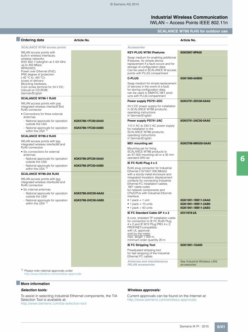
6/41Siemens IK PI · 2015
Industrial Wireless CommunicationIWLAN – Access Points IEEE 802.11n
SCALANCE W786 RJ45 for outdoor use
6
■ Ordering data Article No. Article No.
1) Please note national approvals under http://www.siemens.com/wireless-approvals
■ More information
Selection tools:
To assist in selecting Industrial Ethernet components, the TIA Selection Tool is available at:http://www.siemens.com/tia-selection-tool
Wireless approvals:
Current approvals can be found on the Internet at: http://www.siemens.com/wireless-approvals
SCALANCE W786 access points
IWLAN access points with built-in wireless interfaces; wireless networksIEEE 802.11a/b/g/h/n at 2.4/5 GHz up to 450 Mbps; WPA2/AES; Power over Ethernet (PoE),IP65 degree of protection(-40 °C to +60 °C); scope of delivery: Mounting hardware, 2-pin screw terminal for 24 V DC; manual on CD-ROM; German/English
SCALANCE W786-1 RJ45
IWLAN access points with one integrated wireless interface and RJ45 connector • Connections for three external
antennas - National approvals for operation
outside the USA6GK5786-1FC00-0AA0
- National approvals for operation within the USA 1)
6GK5786-1FC00-0AB0
SCALANCE W786-2 RJ45
IWLAN access points with two integrated wireless interfaces and RJ45 connection• Six connections for external
antennas- National approvals for operation
outside the USA6GK5786-2FC00-0AA0
- National approvals for operation within the USA 1)
6GK5786-2FC00-0AB0
SCALANCE W786-2IA RJ45
IWLAN access points with two integrated wireless interfaces and RJ45 connection• Six internal antennas
- National approvals for operation outside the USA
6GK5786-2HC00-0AA0
- National approvals for operation within the USA 1)
6GK5786-2HC00-0AB0
Accessories
KEY-PLUG W780 iFeatures 6GK5907-8PA00
Swap medium for enabling additional iFeatures, for simple device replacement if a fault occurs and for storage of configuration data; Can be used in SCALANCE W access points with PLUG compartment
C-PLUG 6GK1900-0AB00
Swap medium for simple replacement of devices in the event of a fault; for storing configuration data; can be used in SIMATIC NET prod-ucts with PLUG compartment
Power supply PS791-2DC 6GK5791-2DC00-0AA0
24 V DC power supply for installation in SCALANCE W786 products;operating instructionsin German/English
Power supply PS791-2AC 6GK5791-2AC00-0AA0
110 V AC to 230 V AC power supply for installation in the SCALANCE W786 products; operating instructionsin German/English
MS1 mounting set 6GK5798-8MG00-0AA0
Mounting set for fixing SCALANCE W786 products to an S7-300 mounting rail or a 35 mm standard DIN rail
IE FC RJ45 Plug 4 x 2
RJ45 plug connector for Industrial Ethernet (10/100/1 000 Mbit/s) with a sturdy metal enclosure and integrated insulation displacement contacts for connecting Industrial Ethernet FC installation cables; 180° cable outlet; for network components and CPs/CPUs with Industrial Ethernet interface• 1 pack = 1 unit 6GK1901-1BB11-2AA0• 1 pack = 10 units 6GK1901-1BB11-2AB0• 1 pack = 50 units 6GK1901-1BB11-2AE0
IE FC Standard Cable GP 4 x 2 6XV1878-2A
8-core, shielded TP installation cable for connection to IE FC RJ45 Plug 4 x 2 and IE M12 Plug PRO 4 x 2; PROFINET-compatible; with UL approval; sold by the meter; max. length 1 000 m, minimum order quantity 20 m
IE FC Stripping Tool 6GK1901-1GA00
Preadjusted stripping tool for fast stripping of the Industrial Ethernet FC cables
Antennas and miscellaneous IWLAN accessories
See Industrial Wireless LAN/accessories
Kap_06_IWC_en.book Seite 41 Dienstag, 7. Oktober 2014 1:47 13
© Siemens AG 2014

6/42 Siemens IK PI · 2015
Industrial Wireless CommunicationIWLAN – Access Points IEEE 802.11n
SCALANCE W786 SFP for outdoor use
6
■ Overview
• Particularly well-suited to applications with high climatic requirements when installed outdoors and in areas accessible to the public
■ Design
• Rugged, impact-resistant plastic enclosure, shock and vibration-proof for demanding mechanical requirements
• Two slots for SFP plug-in transceivers (optical 2-port switch)• High IP65 degree of protection against dust and water jets• For use at ambient temperatures from -40 °C to +60 °C
(depending on the SFP plug-in transceiver used)• Resistant to condensation • Resistant to UV radiation and saltwater spray• Design for use outdoors• 6 x R-SMA sockets for the connection of remote antennas• 1 x 24 V DC connector, optional operation with 12 to 24 V DC
or 100 to 240 V AC with power supply that can be integrated in the device
• 1 x PLUG compartment (KEY-PLUG/C-PLUG)• Function LEDs for optical signaling of faults/errors and
operating statuses• Mounting: Wall or, with optional mounting set, on S7 mounting
rail, 35 mm standard mounting rail, or on a pole
Design and interfaces of the SCALANCE W786-2 SFP access points
Product versions
SCALANCE W786-2 SFP • Two wireless cards permanently installed in the device; can be
expanded to establish wireless connections with KEY-PLUG W780 iFeatures
PLUGslot
Reset button
Infeed of 24 V DC or with power supplies 100-240 V AC or12-24 V DC (redundant) 6 x connections for
antennas R-SMA (female)
2 SFP slots with integrated 2-port switch
Kap_06_IWC_en.book Seite 42 Dienstag, 7. Oktober 2014 1:47 13
© Siemens AG 2014

6/43Siemens IK PI · 2015
Industrial Wireless CommunicationIWLAN – Access Points IEEE 802.11n
SCALANCE W786 SFP for outdoor use
6
■ Function
In the case of access points with two wireless modules, one module implements communication of the access points with each other. The radio link for the stations, e.g. a mobile crane system, is established by the second wireless module. Wireless coverage of larger areas can therefore be provided with the same device.
If the minimum length of standard Ethernet cables is insufficient due to the large distance of the access points from the wired
network, SCALANCE W786-2 SFP with SFP plug-in transceivers can be used. Depending on the optical plug-in transceivers used, ranges of up to 70 km can then be achieved.
In the case of SCALANCE W786, this only concerns access points which can, however, be configured as client modules through Web-based management. Then, depending on the selected variant, a maximum of one radio module will be avail-able as a client.
Use of the SCALANCE W786-2 SFP product line in areas subject to demanding climatic requirements
AntennaANT793-8DJ
AntennaANT793-6DG
Radio cell
SCALANCE W786-1 RJ45
SCALANCE W786-2 SFP
Kap_06_IWC_en.book Seite 43 Dienstag, 7. Oktober 2014 1:47 13
© Siemens AG 2014
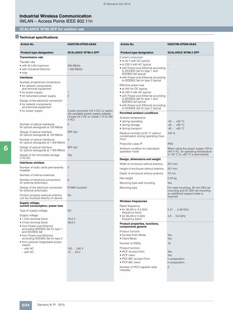
6/44 Siemens IK PI · 2015
Industrial Wireless CommunicationIWLAN – Access Points IEEE 802.11n
SCALANCE W786 SFP for outdoor use
6
■ Technical specifications
Article No. 6GK5786-2FE00-0AA0
Product-type designation SCALANCE W786-2 SFP
Transmission rate
Transfer rate• with W-LAN maximum 450 Mbit/s• with Industrial Ethernet 1 000 Mbit/s• note -
Interfaces
Number of electrical connections• for network components
and terminal equipment-
• for power supply 1• for redundant power supply 0
Design of the electrical connection• for network components
and terminal equipment-
• for power supply 2-pole connector (24 V DC) or option-ally available power supply adapter (4-pole 24 V DC or 3-pole 110 to 230 V AC)
Number of optical interfacesfor optical waveguide at 100 Mbit/s
2
Design of optical interfacefor optical waveguide at 100 Mbit/s
SFP slot
Number of optical interfacesfor optical waveguide at 1 000 Mbit/s
2
Design of optical interfacefor optical waveguide at 1 000 Mbit/s
SFP slot
design of the removable storage C-PLUG
Yes
Interfaces wireless
Number of radio cards permanently installed
2
Number of internal antennas -
Number of electrical connectionsfor external antenna(s)
6
Design of the electrical connectionfor external antenna(s)
R-SMA (socket)
Product property external antenna can be mounted directly on device
No
Supply voltage, current consumption, power loss
Type of supply voltage DC
Supply voltage• 1 from terminal block 19.2 V• 2 from terminal block 28.8 V• from Power-over-Ethernet
according IEEE802.3at for type 1 and IEEE802.3af
-
• from Power-over-Ethernetaccording IEEE802.3at for type 2
-
• from optional integratable power supply- with AC 100 … 240 V- with DC 12 … 24 V
Current consumed• at 24 V with DC typical -• at 230 V with AC typical -• with Power-over-Ethernet according
to IEEE802.3at for type 1 and IEEE802.3af typical
-
• with Power-over-Ethernet according to IEEE802.3at for type 2 typical
-
Effective power loss• at 24V for DC typical -• at 230 V with AC typical -• with Power-over-Ethernet according
to IEEE802.3at for type 1 and IEEE802.3af typical
-
• with Power-over-Ethernet according to IEEE802.3at for type 2 typical
-
Permitted ambient conditions
Ambient temperature• during operating -40 … +60 °C• during storage -40 … +85 °C• during transport -40 … +85 °C
Relative humidity at 25 °C without condensation during operating maxi-mum
100 %
Protection class IP IP65
Ambient condition for (standard) operation mode
When using the power supply 100 to 240 V AC, an operating temperature of -40 °C to +60 °C is permissible
Design, dimensions and weight
Width of enclosure without antenna 251 mm
Height of enclosure without antenna 251 mm
Depth of enclosure without antenna 72 mm
Net weight 2.24 kg
Mounting type wall mounting Yes
Mounting type For mast mounting, 35 mm DIN rail mounting and S7-300 rail mounting, an additional support plate is required
Wireless frequencies
Radio frequency• for WLAN in 2.4 GHz
frequency band2.41 … 2.48 GHz
• for WLAN in 5 GHz frequency band
4.9 … 5.8 GHz
Product properties, functions, components general
Product function• Access Point Mode Yes• Client Mode Yes
Number of SSIDs 16
Product function• iPCF Access Point Yes• iPCF client Yes• iPCF-MC Access Point in preparation• iPCF-MC client in preparation
Number of iPCF-capable radio modules
2
Article No. 6GK5786-2FE00-0AA0
Product-type designation SCALANCE W786-2 SFP
Kap_06_IWC_en.book Seite 44 Dienstag, 7. Oktober 2014 1:47 13
© Siemens AG 2014

6/45Siemens IK PI · 2015
6
■ Technical specifications (continued)
Industrial Wireless CommunicationIWLAN – Access Points IEEE 802.11n
SCALANCE W786 SFP for outdoor use
Product functions management, configuration
Number of manageable IP addresses in client
8
Product function• CLI Yes• web-based management Yes• MIB support Yes• TRAPs via email Yes• Configuration with STEP 7 in preparation• configuration with STEP 7 in the TIA
Portalin preparation
• operation with IWLAN controller No• operation with Enterasys WLAN
controllerNo
• forced roaming with IWLAN Yes• WDS Yes
Protocol is supported• Address Resolution Protocol (ARP) Yes• ICMP Yes• Telnet Yes• HTTP Yes• HTTPS Yes• TFTP Yes• SNMP v1 Yes• SNMP v2 Yes• SNMP v3 Yes• DCP Yes• LLDP Yes
Identification & maintenance function• I&M0 - device-specific information Yes• I&M1 – higher level designation/lo-
cation designationYes
Product functions Diagnosis
Product function• PROFINET IO diagnosis in preparation• localization via Aeroscout in preparation• SysLog Yes
Product functions VLAN
Product function function VLAN with IWLAN
Yes
Product functions DHCP
Product function• DHCP client Yes• in Client Mode DHCP server
via LANNo
Product functions Redundancy
Protocol is supported STP/RSTP Yes
Product functions Security
Product function• ACL - MAC-based -• Management security,
ACL-IP basedYes
• IEEE 802.1x (radius) Yes• NAT/NAPT No• access protection
according to IEEE802.11iYes
• WPA/WPA2 Yes• TKIP/AES Yes
Protocol is supported SSH Yes
Article No. 6GK5786-2FE00-0AA0
Product-type designation SCALANCE W786-2 SFP
Product functions Time
Protocol is supported• SNTP Yes• SIMATIC Time Yes
Standards, specifications, approvals
Standard• for hazardous zone EN 60079-15:2005,
EN 60079-0:2006, II 3 G Ex nA II T4 KEMA 07 ATEX 0145X
• for safety of CSA and UL UL 60950-1 CSA C22.2 No. 60950-1
Verification of suitability• CE mark Yes• EC declaration of conformity Yes• C-Tick Yes• CCC -• Railway application
in accordance with EN 50155No
• e1 approval• E1 approval No• NEMA4X Yes• Power-over-Ethernet
according IEEE802.3at for type 1 and IEEE802.3af
No
• Power-over-Ethernet according to IEEE802.3at for type 2
No
Standard for wireless communication• IEEE 802.11a Yes• IEEE 802.11b Yes• IEEE 802.11e Yes• IEEE 802.11g Yes• IEEE 802.11h Yes• IEEE 802.11i Yes• IEEE 802.11n Yes
Wireless approval You will find the current list of countries at: www.siemens.com/wireless-approvals
Accessories
Accessories 24 V DC screw terminal included in scope of delivery
Article No. 6GK5786-2FE00-0AA0
Product-type designation SCALANCE W786-2 SFP
Kap_06_IWC_en.book Seite 45 Dienstag, 7. Oktober 2014 1:47 13
© Siemens AG 2014

6/46 Siemens IK PI · 2015
Industrial Wireless CommunicationIWLAN – Access Points IEEE 802.11n
SCALANCE W786 SFP for outdoor use
6
■ Ordering data Article No.
1) Please note national approvals under http://www.siemens.com/wireless-approvals
■ More information
Selection tools:
To assist in selecting Industrial Ethernet components, the TIA Selection Tool is available at:http://www.siemens.com/tia-selection-tool
Wireless approvals:
Current approvals can be found on the Internet at: http://www.siemens.com/wireless-approvals
SCALANCE W786 access points
IWLAN access points with built-in wireless interfaces; wireless networksIEEE 802.11a/b/g/h/n at 2.4/5 GHz up to 450 Mbit/s; WPA2/AES; Power over Ethernet (PoE),IP65 degree of protection (-40 °C to +60 °C); scope of delivery: Mounting hardware, 2-pin screw terminal for 24 V DC; manual on CD-ROM; German/English
SCALANCE W786-2 SFP
IWLAN access points with two integrated wireless interfaces and RJ45 connection• Six external antennas
- National approvals for operation outside the USA
6GK5786-2FE00-0AA0
- National approvalsfor operation within the USA 1)
6GK5786-2FE00-0AB0
Accessories
KEY-PLUG W780 iFeatures 6GK5907-8PA00
Swap medium for enabling additional iFeatures, for simple device replacement if a fault occurs and for storage of configuration data; Can be used in SCALANCE W access points with PLUG compart-ment
C-PLUG 6GK1900-0AB00
Swap medium for simple replace-ment of devices in the event of a fault; for storing configuration data; can be used in SIMATIC NET products with PLUG compartment
Power supply PS791-2DC 6GK5791-2DC00-0AA0
24 V DC power supply for installa-tion in SCALANCE W786 products; operating instructions in German/English
Power supply PS791-2AC 6GK5791-2AC00-0AA0
110 V AC to 230 V AC power supply for installation in the SCALANCE W786 products; operating instructions in German/English
MS1 mounting set 6GK5798-8MG00-0AA0
Mounting set for fixing SCALANCE W786 products onto an S7-300 mounting rail or a 35 mm standard DIN rail
Antennas and miscellaneous IWLAN accessories
See Industrial Wireless LAN/accessories
SFP plug-in transceiver
SFP992-1Gigabit, multimode, 750 m
6GK5992-1AL00-8AA0
SFP992-1LD Gigabit, singlemode, 10 km
6GK5992-1AM00-8AA0
SFP992-1LHGigabit, singlemode, 40 km
6GK5992-1AN00-8AA0
SFP992-1LH+Gigabit, singlemode, 70 km
6GK5992-1AP00-8AA0
Fiber-optic cables see Glass fiber-optic cables
Kap_06_IWC_en.book Seite 46 Dienstag, 7. Oktober 2014 1:47 13
© Siemens AG 2014

6/47Siemens IK PI · 2015
Industrial Wireless CommunicationIWLAN – Access Points IEEE 802.11n
SCALANCE W774 RJ45 for use in control cabinet
6
■ Overview
• Access points in SIMATIC design suitable for applications where the device is to be mounted in the control cabinet
■ Design
• Low-profile, compact aluminum enclosure, shock and vibration-proof for high mechanical requirements
• Implementation of simple and cost-effective wireless machine networking
• Support of the 2.4 and 5 GHz frequency band• IP30 protection• For use at ambient temperatures from -20 °C to +60 °C• 2 x R-SMA sockets for the connection of direct mountable and
remote antennas • Antenna placement optimized for the 2x2 MIMO technology;
the antennas do not interfere with each other when they are mounted directly on the device
• 2 x RJ45 connector for 10/100 Mbit/s, of which one connector has Power-over-Ethernet compliant with IEEE 802.3at
• 2 x 24 V DC connection for redundant energy supply• 1 x PLUG compartment for KEY-PLUG/C-PLUG• Function LEDs for optical signaling of faults/errors and
operating statuses• Mounting: Wall, S7-1500 mounting rail, S7-300 mounting rail,
or on 35 mm standard mounting rail• SIMATIC design matches existing components in the control
cabinet (e.g. S7-1500, …)
Design and interfaces of the SCALANCE W774 RJ45 access points
Product versions
SCALANCE W774-1 RJ45• A radio card is permanently installed; functional scope can be
expanded by using a KEY-PLUG W780 iFeatures
2x antenna connections R-SMA (female)
24 V DC connection
2x RJ45 connection 10/100 Mbit/s with integrated 2 port switch; 1 port supports PoE IEEE 802.3at
PLUG slot and reset button
Kap_06_IWC_en.book Seite 47 Dienstag, 7. Oktober 2014 1:47 13
© Siemens AG 2014

6/48 Siemens IK PI · 2015
Industrial Wireless CommunicationIWLAN – Access Points IEEE 802.11n
SCALANCE W774 RJ45 for use in control cabinet
6
■ Function
Integration of an automated guided vehicle system using iPCF with SCALANCE W774-1 RJ45 and KEY-PLUG W780 iFeatures
Radio cell
AntennaANT792-4DN
Han
ger 1
Han
ger 2
Han
ger 3
Han
ger 4
Han
ger 5
G_I
K10
_XX
_301
71
RCoax Cable
Client Module SCALANCE W734-1 RJ45+ KEY-PLUG W740 iFeatures
Access Point SCALANCE W774-1 RJ45+ KEY-PLUG W780 iFeatures
Kap_06_IWC_en.book Seite 48 Dienstag, 7. Oktober 2014 1:47 13
© Siemens AG 2014

6/49Siemens IK PI · 2015
Industrial Wireless CommunicationIWLAN – Access Points IEEE 802.11n
SCALANCE W774 RJ45 for use in control cabinet
6
■ Technical specifications
Article No. 6GK5774-1FX00-0AA06GK5774-1FX00-0AB01)
Product-type designation SCALANCE W774-1 RJ45
Transmission rate
Transmission rate• with W-LAN maximum 300 Mbit/s• with Industrial Ethernet 10 … 100 Mbit/s• note -
Interfaces
Number of electrical connections• for network components
and terminal equipment2
• for power supply 1• for redundant power supply 1
Design of the electrical connection• for network components
and terminal equipmentRJ45 socket
• for power supply 4-pole screw terminal, PoE
Number of optical interfaces for optical waveguide at 100 Mbit/s
-
Design of optical interfacefor optical waveguide at 100 Mbit/s
-
design of the removable storage C-PLUG
Yes
Interfaces wireless
Number of radio cards permanently installed
1
Number of internal antennas -
Number of electrical connections for external antenna(s)
2
Design of the electrical connection for external antenna(s)
R-SMA (socket)
Product property external antenna can be mounted directly on device
Yes
Signal-Inputs/outputs
Number of digital inputs -
Number of digital outputs -
Design of electrical connection at the digital inputs/outputs
-
Signal range• at digital input -• at the digital output -
Supply voltage, current consumption, power loss
Type of supply voltage DC
Supply voltage• 1 from terminal block 19.2 V• 2 from terminal block 28.8 V• from Power-over-Ethernet
according IEEE802.3at for type 1 and IEEE802.3af
48 V
• from Power-over-Ethernet according IEEE802.3at for type 2
-
Current consumed• at 24 V with DC typical 0.25 A• with Power-over-Ethernet
according to IEEE802.3at for type 1 and IEEE802.3af typical
0.125 A
• with Power-over-Ethernet according to IEEE802.3at for type 2 typical
-
Effective power loss• at 24V for DC typical 6 W• with Power-over-Ethernet
according to IEEE802.3at for type 1 and IEEE802.3af typical
6 W
• with Power-over-Ethernet according to IEEE802.3at for type 2 typical
-
Permitted ambient conditions
Ambient temperature• during operating -20 … +60 °C• during storage -40 … +85 °C• during transport -40 … +85 °C
Relative humidity at 25 °C without condensation during operating maximum
97 %
Protection class IP IP30
Ambient condition for (standard) operation mode
When used under hazardous conditions (Zone 2), the SCALANCE W774-1 RJ45 or W734-1 RJ45 prod-uct must be installed in an enclosure. To comply with EN 50021, this enclosure must meet the require-ments of at least IP54 in compliance with EN 60529.
Design, dimensions and weight
Width of enclosure without antenna 26 mm
Height of enclosure without antenna 147 mm
Depth of enclosure without antenna 127 mm
Net weight 0.52 kg
Mounting type wall mounting Yes
Mounting type Wall mounting only if flat mounted
Wireless frequencies
Radio frequency• for WLAN in 2.4 GHz
frequency band2.41 … 2.48 GHz
• for WLAN in 5 GHzfrequency band
4.9 … 5.8 GHz
Article No. 6GK5774-1FX00-0AA06GK5774-1FX00-0AB01)
Product-type designation SCALANCE W774-1 RJ45
Kap_06_IWC_en.book Seite 49 Dienstag, 7. Oktober 2014 1:47 13
© Siemens AG 2014
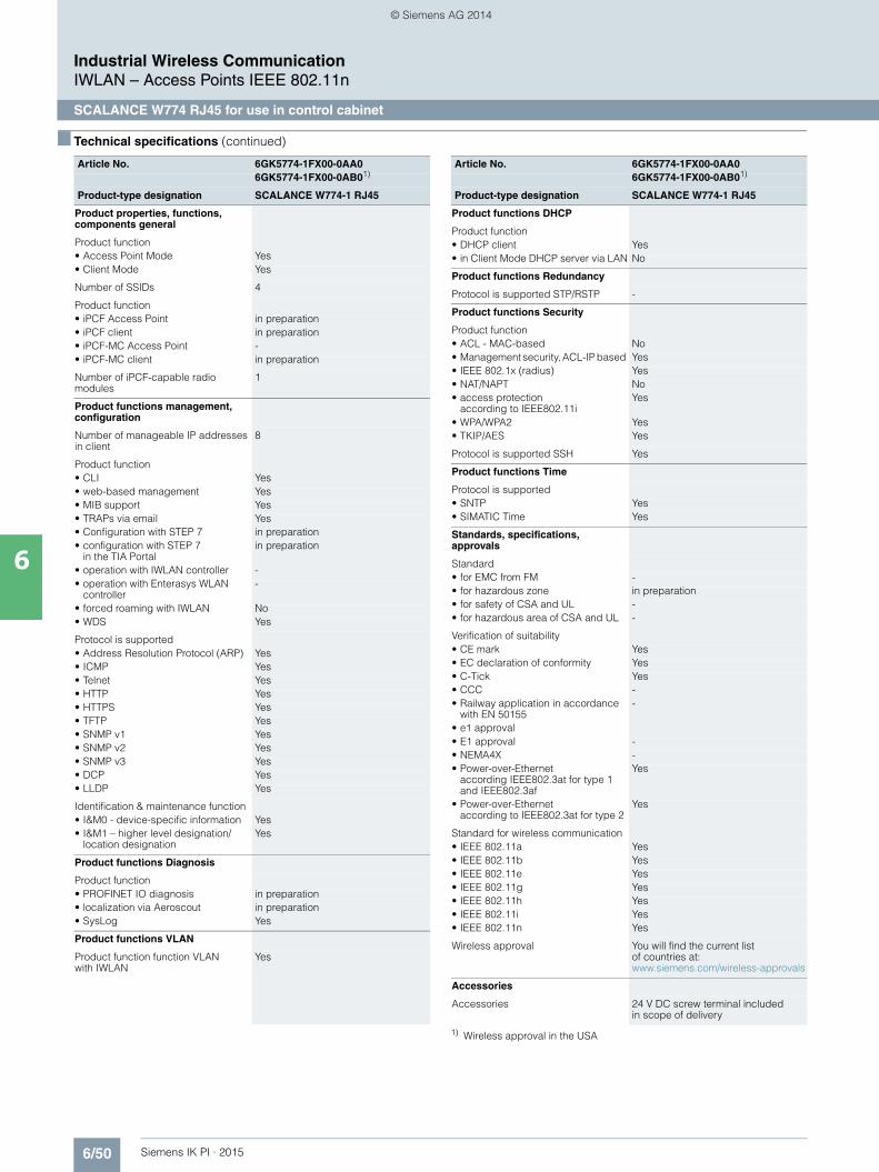
6/50 Siemens IK PI · 2015
6
■ Technical specifications (continued)
Industrial Wireless CommunicationIWLAN – Access Points IEEE 802.11n
SCALANCE W774 RJ45 for use in control cabinet
1) Wireless approval in the USA
Product properties, functions, components general
Product function• Access Point Mode Yes• Client Mode Yes
Number of SSIDs 4
Product function• iPCF Access Point in preparation• iPCF client in preparation• iPCF-MC Access Point -• iPCF-MC client in preparation
Number of iPCF-capable radio modules
1
Product functions management, configuration
Number of manageable IP addresses in client
8
Product function• CLI Yes• web-based management Yes• MIB support Yes• TRAPs via email Yes• Configuration with STEP 7 in preparation• configuration with STEP 7
in the TIA Portalin preparation
• operation with IWLAN controller -• operation with Enterasys WLAN
controller-
• forced roaming with IWLAN No• WDS Yes
Protocol is supported• Address Resolution Protocol (ARP) Yes• ICMP Yes• Telnet Yes• HTTP Yes• HTTPS Yes• TFTP Yes• SNMP v1 Yes• SNMP v2 Yes• SNMP v3 Yes• DCP Yes• LLDP Yes
Identification & maintenance function• I&M0 - device-specific information Yes• I&M1 – higher level designation/
location designationYes
Product functions Diagnosis
Product function• PROFINET IO diagnosis in preparation• localization via Aeroscout in preparation• SysLog Yes
Product functions VLAN
Product function function VLANwith IWLAN
Yes
Article No. 6GK5774-1FX00-0AA06GK5774-1FX00-0AB01)
Product-type designation SCALANCE W774-1 RJ45
Product functions DHCP
Product function• DHCP client Yes• in Client Mode DHCP server via LAN No
Product functions Redundancy
Protocol is supported STP/RSTP -
Product functions Security
Product function• ACL - MAC-based No• Management security, ACL-IP based Yes• IEEE 802.1x (radius) Yes• NAT/NAPT No• access protection
according to IEEE802.11iYes
• WPA/WPA2 Yes• TKIP/AES Yes
Protocol is supported SSH Yes
Product functions Time
Protocol is supported• SNTP Yes• SIMATIC Time Yes
Standards, specifications, approvals
Standard• for EMC from FM -• for hazardous zone in preparation• for safety of CSA and UL -• for hazardous area of CSA and UL -
Verification of suitability• CE mark Yes• EC declaration of conformity Yes• C-Tick Yes• CCC -• Railway application in accordance
with EN 50155-
• e1 approval• E1 approval -• NEMA4X -• Power-over-Ethernet
according IEEE802.3at for type 1 and IEEE802.3af
Yes
• Power-over-Ethernet according to IEEE802.3at for type 2
Yes
Standard for wireless communication• IEEE 802.11a Yes• IEEE 802.11b Yes• IEEE 802.11e Yes• IEEE 802.11g Yes• IEEE 802.11h Yes• IEEE 802.11i Yes• IEEE 802.11n Yes
Wireless approval You will find the current list of countries at: www.siemens.com/wireless-approvals
Accessories
Accessories 24 V DC screw terminal included in scope of delivery
Article No. 6GK5774-1FX00-0AA06GK5774-1FX00-0AB01)
Product-type designation SCALANCE W774-1 RJ45
Kap_06_IWC_en.book Seite 50 Dienstag, 7. Oktober 2014 1:47 13
© Siemens AG 2014
6/51Siemens IK PI · 2015
Industrial Wireless CommunicationIWLAN – Access Points IEEE 802.11n
SCALANCE W774 RJ45 for use in control cabinet
6
■ Ordering data Article No.
1) Please note national approvals under http://www.siemens.com/wireless-approvals
■ More information
Selection tools:
To assist in selecting Industrial Ethernet components, the TIA Selection Tool is available at:
http://www.siemens.com/tia-selection-tool
Wireless approvals:
Current approvals can be found on the Internet at: http://www.siemens.com/wireless-approvals
SCALANCE W774 access points
IWLAN access points with built-in wireless interface for establishing wireless connections with iFeatures; wireless networksIEEE 802.11a/b/g/h/n at 2.4/5 GHz up to 300 Mbit/s; WPA2/AES; integrated 2-port switch; Power over Ethernet (PoE), IP30 degree of protection (-20 °C to +60 °C); scope of delivery: Mounting hardware, 4-pin screw terminal for 24V DC; manual on CD-ROM; German/English
SCALANCE W774-1 RJ45
IWLAN Access Point with one built-in wireless interface• National approvals
for operation outside the USA6GK5774-1FX00-0AA0
• National approvals for operation within the USA 1)
6GK5774-1FX00-0AB0
Accessories
KEY-PLUG W780 iFeatures 6GK5907-8PA00
Swap medium for enabling addi-tional iFeatures, for simple device replacement if a fault occurs and for storage of configuration data; can be used in SCALANCE W access points with PLUG compart-ment
C-PLUG 6GK1900-0AB00
Swap medium for simple replace-ment of devices if a fault occurs;for storing configuration data; can be used in SIMATIC NET prod-ucts with PLUG compartment
IE FC RJ45 Plug 180 2 x 2
RJ45 plug connector for Industrial Ethernet with a rugged metal enclo-sure and integrated insulation-displacement contacts for connect-ing Industrial Ethernet FC installation cables; with a 180° cable outlet; for network components and CPs/CPUs with Industrial Ethernet interface• 1 pack = 1 unit 6GK1901-1BB10-2AA0• 1 pack = 10 units 6GK1901-1BB10-2AB0• 1 pack = 50 units 6GK1901-1BB10-2AE0
IE FC Standard Cable GP 2 x 2 6XV1840-2AH10
4-core, shielded TP installation cable for connection to IE FC outlet RJ45 plug / IE FC RJ45 plug; PROFINET-compliant;with UL approval; sold by the meter; max. quantity 1 000 m, minimum order 20 m
IE FC Stripping Tool 6GK1901-1GA00
Preadjusted stripping toolfor fast stripping of the Industrial Ethernet FC cables
Antennas and miscellaneous IWLAN accessories
See Industrial Wireless LAN/accessories
Kap_06_IWC_en.book Seite 51 Dienstag, 7. Oktober 2014 1:47 13
© Siemens AG 2014

6/52 Siemens IK PI · 2015
Industrial Wireless CommunicationIWLAN – Access Points IEEE 802.11n
SCALANCE W774 M12 EEC for enhanced environmental conditions
6
■ Overview
• Suitable for use in industrial and automation applications in general, but especially in railway applications where the device is to be mounted in the control cabinet
■ Design
• Low-profile, compact aluminum enclosure, shock and vibration-proof for high mechanical requirements
• Special coating of the printed circuit boards (conformal coating)
• Resistant to condensation • Railroad approval in accordance with EN 50155• IP30 degree of protection• For use at ambient temperatures from -20 °C to +60 °C• Support of the 2.4 and 5 GHz frequency band• 2 x R-SMA sockets for the connection of direct mountable and
remote antennas • Antenna placement optimized for the 2x2 MIMO technology;
the antennas do not interfere with each other when they are mounted directly on the device
• 2 x M12 connection for 10/100 Mbit/s, of which one connection with Power-over-Ethernet according to IEEE 802.3at
• 1 x M12 socket for power supply (24 V DC)• 1 x PLUG compartment (KEY-PLUG/C-PLUG)• Function LEDs for optical signaling of faults/errors and
operating statuses• Mounting: Wall, S7-1500 mounting rail, S7-300 mounting rail,
or on 35 mm standard mounting rail
Design and interfaces of the SCALANCE W774 M12 EEC access points
Product version
SCALANCE W774-1 M12 EEC• A radio card is permanently installed; functional scope can be
expanded by using a KEY-PLUG W780 iFeatures
2x antenna connections R-SMA (female)
24 V DC connection
PLUG slot and reset button
2x M12 connection 10/100 Mbit/s with integrated 2 port switch; 1 port supports PoE IEEE 802.3at
Kap_06_IWC_en.book Seite 52 Dienstag, 7. Oktober 2014 1:47 13
© Siemens AG 2014

6/53Siemens IK PI · 2015
Industrial Wireless CommunicationIWLAN – Access Points IEEE 802.11n
SCALANCE W774 M12 EEC for enhanced environmental conditions
6
■ Function
The SCALANCE W774 M12 EEC (Extended Environmental Conditions) are designed for use in railway applications. The devices satisfy EN 50155, the approval for railway appli-cations, and can thus be used for rail traffic. Combined with the antennas approved for railway applications, which are con-nected via R-SMA antenna connectors (female), these products can set up a reliable IWLAN wireless infrastructure.
The devices can be installed at the location that is most favorable for the wireless link. The enclosure and the connectors are resistant to high levels of shock and vibration because all the connectors are screwed or locked. The SCALANCE W774 M12 EEC is well suited to environments in which a compact design plays a large role. Through its coated printed-circuit
boards (Conformal Coating), the module is resistant to conden-sation caused by use in environments with large temperature variations.
SCALANCE W774-1 M12 EEC access points can also be operated as client modules.
Provided that a delay (several 100 ms) caused by roaming in accordance with IEEE 802.11 is tolerated by all communication stations when switching the radio cells, the communication continues uninterrupted.
For real-time requirements, the SCALANCE W774-1 M12 EEC can be equipped with KEY-PLUG functionality for activating iFeatures.
Data transfer in trains with SCALANCE W774-1 M12 EEC
Tablet, smartphone or
laptop
Passenger
G_I
K10_
XX
_303
38
Industrial Ethernet
SCALANCE W774-1M12 EEC
ANT 795-6MN
Kap_06_IWC_en.book Seite 53 Dienstag, 7. Oktober 2014 1:47 13
© Siemens AG 2014

6/54 Siemens IK PI · 2015
Industrial Wireless CommunicationIWLAN – Access Points IEEE 802.11n
SCALANCE W774 M12 EEC for enhanced environmental conditions
6
■ Technical specifications
Article No. 6GK5774-1FY00-0TA06GK5774-1FY00-0TB01)
Product-type designation SCALANCE W774-1 M12 EEC
Transmission rate
Transmission rate• with W-LAN maximum 300 Mbit/s• with Industrial Ethernet 10 … 100 Mbit/s• note -
Interfaces
Number of electrical connections• for network components
and terminal equipment2
• for power supply 1• for redundant power supply 1
Design of electrical connection• for network components
and terminal equipmentM12 interface (4-pole, D-coded),PoE
• for power supply M12 interface (4-pole, A-coded)
Number of optical interfaces for optical waveguide at 100 Mbit/s
-
Design of optical interfacefor optical waveguide at 100 Mbit/s
-
design of the removable storage C-PLUG
Yes
Interfaces wireless
Number of radio cards permanently installed
1
Number of internal antennas -
Number of electrical connectionsfor external antenna(s)
2
Design of the electrical connectionfor external antenna(s)
R-SMA (socket)
Product property external antenna can be mounted directly on device
Yes
Signal-Inputs/outputs
Number of digital inputs -
Number of digital outputs -
Design of electrical connection at the digital inputs/outputs
-
Signal range• at digital input -• at the digital output -
Supply voltage, current consumption, power loss
Type of supply voltage DC
Supply voltage• 1 from terminal block 19.2 V• 2 from terminal block 28.8 V• from Power-over-Ethernet
according IEEE802.3at for type 1 and IEEE802.3af
48 V
• from Power-over-Ethernet according IEEE802.3at for type 2
-
Current consumed• at 24 V with DC typical -• with Power-over-Ethernet
according to IEEE802.3at for type 1 and IEEE802.3af typical
-
• with Power-over-Ethernet according to IEEE802.3at for type 2 typical
-
Effective power loss• at 24V for DC typical -• with Power-over-Ethernet
according to IEEE802.3at for type 1 and IEEE802.3af typical
-
• with Power-over-Ethernet according to IEEE802.3atfor type 2 typical
-
Permitted ambient conditions
Ambient temperature• during operating -20 ... +60 °C• during storage -40 ... +85 °C• during transport -40 ... +85 °C
Relative humidity at 25 °C without condensation during operating maximum
100 %
Protection class IP
Ambient condition for (standard) operation mode
When used under hazardous conditions (Zone 2), the SCALANCE W774-1 M12 EEC product must be installed in an enclosure. To comply with EN 50021, this enclosure must meet the requirements of at least IP54 in compliance with EN 60529.
Design, dimensions and weight
Width of enclosure without antenna 26 mm
Height of enclosure without antenna 147 mm
Depth of enclosure without antenna 127 mm
Net weight
Mounting type wall mounting Yes
Mounting type Wall mounting only if flat mounted
Wireless frequencies
Radio frequency• for WLAN in 2.4 GHz
frequency band2.41 … 2.48 GHz
• for WLAN in 5 GHz frequency band
4.9 … 5.8 GHz
Product properties, functions, components general
Product function• Access Point Mode Yes• Client Mode Yes
Number of SSIDs 4
Product function• iPCF Access Point in preparation• iPCF client in preparation• iPCF-MC Access Point -• iPCF-MC client in preparation
Number of iPCF-capable radio modules
1
Article No. 6GK5774-1FY00-0TA06GK5774-1FY00-0TB01)
Product-type designation SCALANCE W774-1 M12 EEC
Kap_06_IWC_en.book Seite 54 Dienstag, 7. Oktober 2014 1:47 13
© Siemens AG 2014

6/55Siemens IK PI · 2015
6
■ Technical specifications (continued)
Industrial Wireless CommunicationIWLAN – Access Points IEEE 802.11n
SCALANCE W774 M12 EEC for enhanced environmental conditions
1) Wireless approval in the USA
Product functions management, configuration
Number of manageable IP addresses in client
8
Product function• CLI Yes• web-based management Yes• MIB support Yes• TRAPs via email Yes• Configuration with STEP 7 in preparation• configuration with STEP 7
in the TIA Portalin preparation
• operation with IWLAN controller -• operation with Enterasys WLAN
controller-
• forced roaming with IWLAN No• WDS Yes
Protocol is supported• Address Resolution Protocol (ARP) Yes• ICMP Yes• Telnet Yes• HTTP Yes• HTTPS Yes• TFTP Yes• SNMP v1 Yes• SNMP v2 Yes• SNMP v3 Yes• DCP Yes• LLDP Yes
Identification & maintenance function• I&M0 - device-specific information Yes• I&M1 – higher level designation/
location designationYes
Product functions Diagnosis
Product function• PROFINET IO diagnosis in preparation• localization via Aeroscout in preparation• SysLog Yes
Product functions VLAN
Product function function VLAN with IWLAN
Yes
Product functions DHCP
Product function• DHCP client Yes• in Client Mode DHCP server
via LANNo
Product functions Redundancy
Protocol is supported STP/RSTP Yes
Product functions Security
Product function• ACL - MAC-based No• Management security,
ACL-IP basedYes
• IEEE 802.1x (radius) Yes• NAT/NAPT No• access protection
according to IEEE802.11iYes
• WPA/WPA2 Yes• TKIP/AES Yes
Protocol is supported SSH Yes
Article No. 6GK5774-1FY00-0TA06GK5774-1FY00-0TB01)
Product-type designation SCALANCE W774-1 M12 EEC
Product functions Time
Protocol is supported• SNTP Yes• SIMATIC Time Yes
Standards, specifications, approvals
Standard• for EMC from FM in preparation• for hazardous zone in preparation• for safety of CSA and UL in preparation• for hazardous area of CSA and UL
Verification of suitability• CE mark Yes• EC declaration of conformity Yes• C-Tick Yes• CCC -• Railway application in accordance
with EN 50155in preparation
• e1 approval• E1 approval -• NEMA4X -• Power-over-Ethernet
according IEEE802.3at for type 1 and IEEE802.3af
Yes
• Power-over-Ethernet according to IEEE802.3at for type 2
Yes
Standard for wireless communication• IEEE 802.11a Yes• IEEE 802.11b Yes• IEEE 802.11e Yes• IEEE 802.11g Yes• IEEE 802.11h Yes• IEEE 802.11i Yes• IEEE 802.11n Yes
Wireless approval You will find the current list of countries at: www.siemens.com/wireless-approvals
Accessories
Accessories -
Article No. 6GK5774-1FY00-0TA06GK5774-1FY00-0TB01)
Product-type designation SCALANCE W774-1 M12 EEC
Kap_06_IWC_en.book Seite 55 Dienstag, 7. Oktober 2014 1:47 13
© Siemens AG 2014

6/56 Siemens IK PI · 2015
Industrial Wireless CommunicationIWLAN – Access Points IEEE 802.11n
SCALANCE W774 M12 EEC for enhanced environmental conditions
6
■ Ordering data Article No.
1) Please note national approvals under http://www.siemens.com/wireless-approvals
■ More information
Selection tools:
To assist in selecting Industrial Ethernet components, the TIA Selection Tool is available at:http://www.siemens.com/tia-selection-tool
Wireless approvals:
Current approvals can be found on the Internet at: http://www.siemens.com/wireless-approvals
SCALANCE W774 M12 EEC Access Points
IWLAN Access Points with built-in wireless interface;wireless networksIEEE 802.11a/b/g/h/n at 2.4/5 GHz up to 300 Mbit/s; railway approval in accordance with EN 50155; conformal coating;WPA2/AES; Power over Ethernet (PoE),IP20 degree of protection; scope of delivery: Mounting hardware; manual on CD-ROM, German/English
SCALANCE W774-1 M12 EEC
IWLAN Access Point with one integrated wireless interface• National approvals
for operation outside the USA6GK5774-1FY00-0TA0
• National approvals for operation within the USA 1)
6GK5774-1FY00-0TB0
Accessories
KEY-PLUG W780 iFeatures 6GK5907-8PA00
Swap medium for enabling additional iFeatures, for simple device replacement if a fault occurs and for storage of configuration data; Can be used in SCALANCE W access points with PLUG compart-ment
C-PLUG 6GK1900-0AB00
Swap medium for simple replace-ment of devices in the event of a fault; for storing configuration data;can be used in SIMATIC NET products with PLUG compartment
IE FC M12 Plug PRO 2 x 2
M12 plug-in connector (D-coded, IP65/IP67) that can be assembled in the field, metal enclosure, FastConnect connection method, for SCALANCE W774-1 M12 EEC• 1 unit 6GK1901-0DB20-6AA0• 8 units 6GK1901-0DB30-6AA8
IE FC Standard Cable GP 2 x 2 /Type A
6XV1840-2AH10
4-core, shielded TP installation cable for connection to IE FC Outlet RJ45/ IE FC RJ45 Plug; PROFINET-compatible; with UL approval; sold by the meter;max. length 1 000 m, minimum order 20 m
IE FC Stripping Tool 6GK1901-1GA00
Preadjusted stripping toolfor fast stripping of the Industrial Ethernet FC cables
Power M12 Cable Connector PRO 6GK1907-0DC10-6AA3
Terminal socket for connection of SCALANCE W700 for 24 V DC supply voltage; 4-pole, A-coded, with assembly instructions, 3 units
Power Cable 2 x 0.75 6XV1812-8A
Connecting cable for Power M12 Cable Connector PRO, sold by the meter
Antennas and miscellaneous IWLAN accessories
See Industrial Wireless LAN/accessories
Kap_06_IWC_en.book Seite 56 Dienstag, 7. Oktober 2014 1:47 13
© Siemens AG 2014
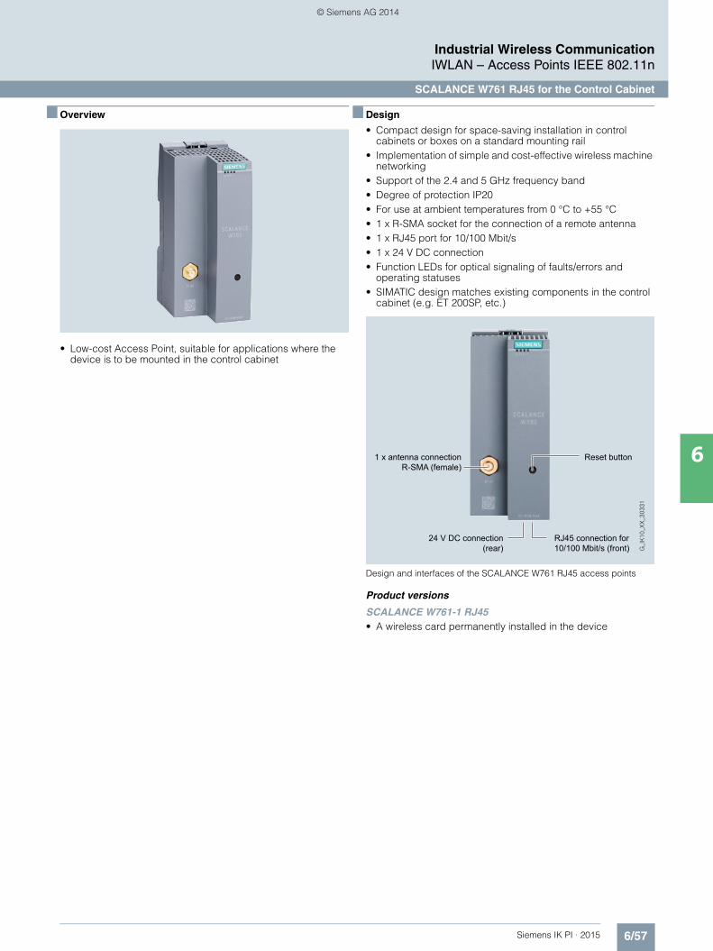
6/57Siemens IK PI · 2015
Industrial Wireless CommunicationIWLAN – Access Points IEEE 802.11n
SCALANCE W761 RJ45 for the Control Cabinet
6
■ Overview
• Low-cost Access Point, suitable for applications where the device is to be mounted in the control cabinet
■ Design
• Compact design for space-saving installation in control cabinets or boxes on a standard mounting rail
• Implementation of simple and cost-effective wireless machine networking
• Support of the 2.4 and 5 GHz frequency band• Degree of protection IP20 • For use at ambient temperatures from 0 °C to +55 °C • 1 x R-SMA socket for the connection of a remote antenna • 1 x RJ45 port for 10/100 Mbit/s • 1 x 24 V DC connection • Function LEDs for optical signaling of faults/errors and
operating statuses• SIMATIC design matches existing components in the control
cabinet (e.g. ET 200SP, etc.)
Design and interfaces of the SCALANCE W761 RJ45 access points
Product versions
SCALANCE W761-1 RJ45• A wireless card permanently installed in the device
1 x antenna connection R-SMA (female)
24 V DC connection (rear)
RJ45 connection for 10/100 Mbit/s (front)
Reset button
Kap_06_IWC_en.book Seite 57 Dienstag, 7. Oktober 2014 1:47 13
© Siemens AG 2014
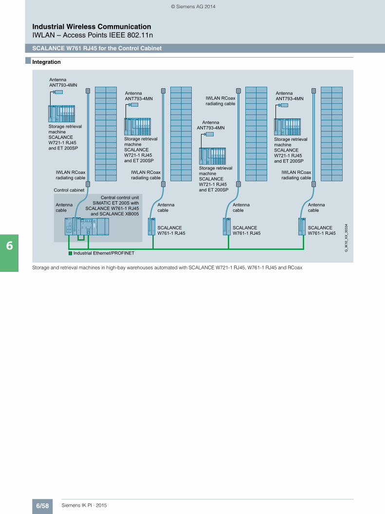
6/58 Siemens IK PI · 2015
Industrial Wireless CommunicationIWLAN – Access Points IEEE 802.11n
SCALANCE W761 RJ45 for the Control Cabinet
6
■ Integration
Storage and retrieval machines in high-bay warehouses automated with SCALANCE W721-1 RJ45, W761-1 RJ45 and RCoax
Antenna cable
Antenna ANT793-4MN
Antenna cable
Antenna cable
Antenna cable
Control cabinetCentral control unit
SIMATIC ET 200S with SCALANCE W761-1 RJ45
and SCALANCE XB005
IWLAN RCoax radiating cable
IWLAN RCoax radiating cable
IWLAN RCoax radiating cable
IWLAN RCoax radiating cable
Storage retrieval machine SCALANCE W721-1 RJ45and ET 200SP
Storage retrieval machine SCALANCE W721-1 RJ45and ET 200SP
Storage retrieval machine SCALANCE W721-1 RJ45and ET 200SP
Storage retrieval machine SCALANCE W721-1 RJ45and ET 200SP
Antenna ANT793-4MN
Antenna ANT793-4MN
Antenna ANT793-4MN
G_I
K10
_XX
_303
34
Industrial Ethernet/PROFINET
SCALANCE W761-1 RJ45
SCALANCE W761-1 RJ45
SCALANCE W761-1 RJ45
Kap_06_IWC_en.book Seite 58 Dienstag, 7. Oktober 2014 1:47 13
© Siemens AG 2014

6/59Siemens IK PI · 2015
Industrial Wireless CommunicationIWLAN – Access Points IEEE 802.11n
SCALANCE W761 RJ45 for the Control Cabinet
6
■ Technical specifications
Article no. 6GK5761-1FC00-0AA06GK5761-1FC00-0AB01)
Product-type designation SCALANCE W761-1 RJ45
Transmission rate
Transmission rate• with W-LAN maximum 150 Mbit/s• for Industrial Ethernet 10 … 100 Mbit/s
Interfaces
Number of electrical connections• for network components and
terminal equipment1
• for power supply 1• for redundant power supply 0
Design of electrical connection• for network components and
terminal equipmentRJ45 socket
• for power supply 3-pole screw terminal
Number of optical interfaces for optical waveguide at 100 Mbit/s
-
Design of optical interface for optical waveguide at 100 Mbit/s
-
design of the removable storage C-PLUG
No
Interfaces wireless
Number of radio cards permanently installed
1
Number of internal antennas -
Number of electrical connections for external antenna(s)
1
Design of the electrical connection for external antenna(s)
R-SMA (socket)
Product property external antenna can be mounted directly on device
Yes
Supply voltage, current consumption, power loss
Type of supply voltage DC
Supply voltage• 1 from terminal block 19.2 V• 2 from terminal block 28.8 V• from Power-over-Ethernet according
IEEE802.3at for type 1 and IEEE802.3af
-
• from Power-over-Ethernet according IEEE802.3at for type 2
-
Current consumed• at 24 V with DC typical 0.15 A• with Power-over-Ethernet according
to IEEE802.3at for type 1 and IEEE802.3af typical
-
• with Power-over-Ethernet according to IEEE802.3at for type 2 typical
-
Effective power loss• at 24V for DC typical 3.6 W• with Power-over-Ethernet according
to IEEE802.3at for type 1 and IEEE802.3af typical
-
• with Power-over-Ethernet according to IEEE802.3at for type 2 typical
-
Permitted ambient conditions
Ambient temperature• during operating 0 … 55 °C• during storage -40 … +85 °C• during transport -40 … +85 °C
Relative humidity at 25 °C without condensation during operating maximum
95 %
Protection class IP IP20
Ambient condition for (standard) operation mode
When used under hazardous conditions (Zone 2), the SCALANCE W761-1 RJ45 or W72x-1 RJ45 product must be installed in an enclosure. To comply with EN 50021, this enclosure must meet the require-ments of at least IP54 in compliance with EN 60529.
Design, dimensions and weight
Width of enclosure without antenna 50 mm
Height of enclosure without antenna 114 mm
Depth of enclosure without antenna 74 mm
Net weight 0.13 kg
Mounting type wall mounting No
Wireless frequencies
Radio frequency• for WLAN in 2.4 GHz frequency
band2.41 … 2.48 GHz
• for WLAN in 5 GHz frequency band 4.9 … 5.8 GHz
Product properties, functions, components general
Product function• Access Point Mode Yes• Client Mode Yes
Number of SSIDs 1
Product function• iPCF Access Point No• iPCF client No• iPCF-MC Access Point No• iPCF-MC client No
Number of iPCF-capable radio modules
0
Article no. 6GK5761-1FC00-0AA06GK5761-1FC00-0AB01)
Product-type designation SCALANCE W761-1 RJ45
Kap_06_IWC_en.book Seite 59 Dienstag, 7. Oktober 2014 1:47 13
© Siemens AG 2014

6/60 Siemens IK PI · 2015
6
■ Technical specifications (continued)
Industrial Wireless CommunicationIWLAN – Access Points IEEE 802.11n
SCALANCE W761 RJ45 for the Control Cabinet
1) Wireless approval in the USA
Product functions management, configuration
Number of manageable IP addresses in client
4
Product function• CLI Yes• web-based management Yes• MIB support Yes• TRAPs via email Yes• Configuration with STEP 7 in preparation• configuration with STEP 7
in the TIA Portalin preparation
• operation with IWLAN controller -• operation with Enterasys WLAN
controller-
• forced roaming with IWLAN No• WDS Yes
Protocol is supported• Address Resolution Protocol (ARP) Yes• ICMP Yes• Telnet Yes• HTTP Yes• HTTPS Yes• TFTP Yes• SNMP v1 Yes• SNMP v2 Yes• SNMP v3 Yes• DCP Yes• LLDP Yes
Identification & maintenance function• I&M0 - device-specific information Yes• I&M1 – higher level designation/
location designationYes
Product functions Diagnosis
Product function• PROFINET IO diagnosis in preparation• localization via Aeroscout No• SysLog Yes
Product functions VLAN
Product function function VLAN with IWLAN
Yes
Product functions DHCP
Product function• DHCP client Yes• in Client Mode DHCP server via LAN No
Product functions Redundancy
Protocol is supported STP/RSTP -
Article no. 6GK5761-1FC00-0AA06GK5761-1FC00-0AB01)
Product-type designation SCALANCE W761-1 RJ45
Product functions Security
Product function• ACL - MAC-based No• Management security,
ACL-IP basedYes
• IEEE 802.1x (radius) Yes• NAT/NAPT No• access protection
according to IEEE802.11iYes
• WPA/WPA2 Yes• TKIP/AES Yes
Protocol is supported SSH Yes
Product functions Time
Protocol is supported• SNTP Yes• SIMATIC Time Yes
Standards, specifications, approvals
Standard• for EMC from FM -• for hazardous zone in preparation• for safety of CSA and UL -• for hazardous area of CSA and UL -
Verification of suitability• CE mark Yes• EC declaration of conformity Yes• C-Tick Yes• CCC -• Railway application in accordance
with EN 50155-
• e1 approval• E1 approval -• NEMA4X -• Power-over-Ethernet according
IEEE802.3at for type 1 and IEEE802.3af
No
• Power-over-Ethernet according to IEEE802.3at for type 2
No
Standard for wireless communication• IEEE 802.11a Yes• IEEE 802.11b Yes• IEEE 802.11e Yes• IEEE 802.11g Yes• IEEE 802.11h Yes• IEEE 802.11i Yes• IEEE 802.11n Yes
Wireless approval You will find the current list of countries at: www.siemens.com/wireless-approvals
Accessories
Accessories 24 V DC screw terminal included in scope of delivery
Article no. 6GK5761-1FC00-0AA06GK5761-1FC00-0AB01)
Product-type designation SCALANCE W761-1 RJ45
Kap_06_IWC_en.book Seite 60 Dienstag, 7. Oktober 2014 1:47 13
© Siemens AG 2014
6/61Siemens IK PI · 2015
Industrial Wireless CommunicationIWLAN – Access Points IEEE 802.11n
SCALANCE W761 RJ45 for the Control Cabinet
6
■ Ordering data Article No.
1) Please note national approvals under http://www.siemens.com/wireless-approvals
■ More information
Selection tools:
To assist in selecting Industrial Ethernet components, the TIA Selection Tool is available at:http://www.siemens.com/tia-selection-tool
Wireless approvals:
Current approvals can be found on the Internet at: http://www.siemens.com/wireless-approvals
SCALANCE W761 Access Points
IWLAN Access Point with built-in wireless interface; wireless networks IEEE 802.11a/b/g/h/n at 2.4/5 GHz up to 150 Mbit/s; WPA2/AES; IP20 degree of protection (0 °C to +55 °C); scope of delivery: Mounting hardware, 3-pin screw terminal for 24V DC; manual on CD-ROM; German/English
SCALANCE W761-1 RJ45
IWLAN Access Point with one built-in wireless interface• National approvals
for operation outside the USA6GK5761-1FC00-0AA0
• National approvalsfor operation within the USA 1)
6GK5761-1FC00-0AB0
Accessories
IE FC RJ45 Plug 180 2 x 2
RJ45 plug connector for Industrial Ethernet with a rugged metal enclosure and integrated insulation-displacement contacts for connecting Industrial Ethernet FC installation cables; with a 180° cable outlet; for network components and CPs/CPUs with Industrial Ethernet interface• 1 pack = 1 unit 6GK1901-1BB10-2AA0• 1 pack = 10 units 6GK1901-1BB10-2AB0• 1 pack = 50 units 6GK1901-1BB10-2AE0
IE FC Standard Cable GP 2 x 2 6XV1840-2AH10
4-core, shielded TP installation cable for connection to IE FC outlet RJ45 plug / IE FC RJ45 plug; PROFINET-compliant; with UL approval; sold by the meter; max. quantity 1 000 m, minimum order 20 m
IE FC stripping tool 6GK1901-1GA00
Preadjusted stripping toolfor fast stripping of the Industrial Ethernet FC cables
Antennas and miscellaneous IWLAN accessories
See Industrial Wireless LAN/accessories
Kap_06_IWC_en.book Seite 61 Dienstag, 7. Oktober 2014 1:47 13
© Siemens AG 2014

6/62 Siemens IK PI · 2015
Industrial Wireless CommunicationIWLAN – Controller and Controller Access Points IEEE 802.11n
Overview
6
■ Overview
The network infrastructures in the industrial and office areas are coming ever-closer together. This applies also in the area of wireless communication, causing a constant increase in the number of access points and WLAN clients to be managed. If such networks are established with a large number of stand-alone access points, with each one having to be configured separately, this results in huge costs for initial configuration and operation.
Central wireless LAN controllers enable low-cost, user-friendly and secure operation of large WLAN infrastructures here. Management of the WLAN clients connected to such WLANs is significantly simplified thanks to their division into user groups with different security policies.
The SCALANCE WLC711 IWLAN Controller is a device for centralized management (configuration, diagnostics, firmware updates, access control, security settings, coordination) of a wireless LAN in the industrial environment.• Fast establishment of a new WLAN or expansion of an existing
WLAN with the help of the SCALANCE W786C and SCALANCE W788C controller-based access points
• Parallel operation of different services (e.g. communication between programmable controllers, Internet access, Voice-over-IP telephony and video transmission) on the same controller-based WLAN infrastructure without requiring additional SSIDs for this purpose.
• Seamless transition between production WLAN and corporate WLAN
• Simplified commissioning as well as increased reliability and security thanks to the central management functions of the IWLAN controller in comparison to a WLAN comprising stand-alone access points that have to be configured individually
■ Benefits
• Reduced commissioning overhead and operation of larger IWLAN installations (up to 48 access points or 96 access points in redundant mode) thanks to configuring from a central location
• Investment protection thanks to seamless integration into existing IWLAN installations or into an existing corporate WLAN
• Saving on redundant infrastructures (e.g. separate network for Internet access and voice transmission) thanks to multiple use of the same infrastructure for different services
• Avoidance of a single point of failure thanks to optional parallel operation of two controllers; the WLAN remains functional even if the controller(s) fail(s)
• Increased reliability when operating the IWLAN through complete, coordinated portfolio of IWLAN Controller SCALANCE WLC711, industrial access points and SCALANCE W client modules, as well as the suitable acces-sories (antennas, connecting cables, power supplies)
• Flexible configuration of networks thanks to the use of an integrated wireless mesh solution
• Dynamic Radio Management supports the optimal alignment of the entire WLAN network
• In the controller-based WLAN, the bandwidth or the assignment of the access points can be automatically influenced by the IWLAN Controller SCALANCE WLC711 depending on the requirements. This ensures optimal utilization of the WLAN by the IWLAN client modules.
Kap_06_IWC_en.book Seite 62 Dienstag, 7. Oktober 2014 1:47 13
© Siemens AG 2014

6/63Siemens IK PI · 2015
Industrial Wireless CommunicationIWLAN – Controller and Controller Access Points IEEE 802.11n
Overview
6
■ Application
Company-wide WLAN based on Extreme Networks (Enterasys) Wireless Controller and SCALANCE WLC711 IWLAN controller
The SCALANCE WLC711 IWLAN controller is the optimum solu-tion for IWLAN installations with up to 48 access points (in redun-dant mode even up to 96 access points). By using SCALANCE W access points and client modules, different applications in the industrial environment or a comparable environment can com-municate via a centrally managed IWLAN. SCALANCE W ac-cess points for controller operation are available for use both outdoors and for cabinet-free use in an industrial environment (e.g. on the shop floor).
The SCALANCE WLC711 IWLAN controller can be integrated in the corporate WLAN and allows the implementation of a WLAN throughout the office, outdoor and industrial areas. This allows use of mobile WLAN phones, laptops, smart phones and tablets in the same wireless network, while complying with security policies for different user groups, and guaranteeing defined quality of service (QoS) for different devices.
Office network Plant network
Seamless roaming between office- and plant networksS7-300 with CP 343-1
Network management
S7-300 with CP 343-1
WLAN telephone
IP telephone system
IP telephoneDatabase
Smartphone
EnterasysAP3705(IEEE 802.11a/b/g)
SCALANCE W786C-2 RJ45
(IEEE 802.11a/b/g/n)
SCALANCE W788C(IEEE 802.11a/b/g/n)
EnterasysAP3710i
(IEEE 802.11a/b/g/n)
Enterasys Wireless Controller
Laptop
Router
SCALANCE W748-1 RJ45
Ethernet
Industrial Ethernet
G_I
K10
_XX
_301
75
SCALANCE WLC711 IWLAN Controller
Kap_06_IWC_en.book Seite 63 Dienstag, 7. Oktober 2014 1:47 13
© Siemens AG 2014

6/64 Siemens IK PI · 2015
6
■ Application (continued)
Industrial Wireless CommunicationIWLAN – Controller and Controller Access Points IEEE 802.11n
Overview
Application examples
With the SCALANCE WLC711 IWLAN controller, the benefits of a controller solution, long-familiar in corporate networks, now also become available for typical industrial and industry-related applications:
• Plant-wide wireless infrastructures in factory automation and process automation, e.g. for mobile operator control or logistics applications
• Industry-related applications, e.g. container terminals, road or underground rail tunnels, where IWLAN is required for transmitting visualization, video, and voice data
SCALANCE WLC711 IWLAN controller in redundancy mode
2 x SCALANCE WLC711 in redundancy mode, each licensed for up to 48 access points (tunnel 1 and tunnel 2)
2 x SCALANCE WLC711 in redundancy mode, each licensed for up to 48 access points (tunnel 3 and tunnel 4) G
_IK
10_X
X_3
0274
Industrial Ethernet
1
...322
SCALANCE W786C
SCALANCE W786C
SCALANCE W788C
1
...322
Industrial Ethernet
SCALANCE XR552-12M
SCALANCE XR552-12M
SCALANCE XR324-12M
SCALANCE XR324-12M
1
...162
SCALANCE W786C
SCALANCE W786C
SCALANCE W788C
1
...162
Kap_06_IWC_en.book Seite 64 Dienstag, 7. Oktober 2014 1:47 13
© Siemens AG 2014

6/65Siemens IK PI · 2015
Industrial Wireless CommunicationIWLAN – Controller and Controller Access Points IEEE 802.11n
Overview
6
■ Function
Fundamental principles of the controller-based Industrial Wireless LAN
The SCALANCE WLC711 IWLAN controller enables centralized management of an Industrial Wireless LAN. It automatically detects new access points, establishes a connection to them, and manages and coordinates access points and clients. Thanks to the Layer 3 architecture, access points located in different Layer 2 subnets can also be managed. This function allows wireless expansion of an existing Ethernet network with-out having to make changes to the existing network topology.
With the IWLAN controller, the IWLAN wireless infrastructure can be divided into logical, service-based networks (Virtual Network Services). Different services, security requirements and access criteria can thus be reliably managed, and different user groups such as administrators, commissioning engineers, or visitors can use the same wireless network.
In the same way, different applications such as Voice-over-IP (VoIP), video and Internet access can use the same infrastruc-ture. The result is optimal capacity utilization of the IWLAN network.
If applications with high reliability and availability requirements are to communicate wirelessly, either two IWLAN controllers can be operated redundantly or the access points can be set up redundantly (overlapping of the radio links due to two wireless cards in the device).
In applications where cable connections are not possible or are only possible with difficulty, the controller-based access points can be reliably integrated into the network even without a cable connection. Thanks to the mesh algorithms, the access points can resume communication in the event of a network error.
The controller-based access points of the SCALANCE W780C series can only be used with the SCALANCE WLC711 IWLAN controller and can only be configured using this IWLAN control-ler.
The IWLAN controller connects, manages and coordinates all access point and clients such that the WLAN environment appears like several IP subnets with central management. The individual connections are additionally managed here, and the stations can therefore move securely and reliably throughout the entire radio network.
Diagnostics and management functions
As well as centralized management and wireless network con-figuration, the SCALANCE WLC711 IWLAN controller also offers error recording, wireless network monitoring, and documenta-tion of network statistics.
■ More information
Supplementary WLAN solutions for office environments can be found on the Internet at: http://www.extremenetworks.com
Kap_06_IWC_en.book Seite 65 Dienstag, 7. Oktober 2014 1:47 13
© Siemens AG 2014
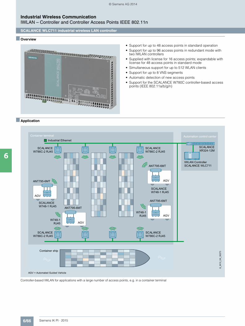
6/66 Siemens IK PI · 2015
Industrial Wireless CommunicationIWLAN – Controller and Controller Access Points IEEE 802.11n
SCALANCE WLC711 industrial wireless LAN controller
6
■ Overview
• Support for up to 48 access points in standard operation• Support for up to 96 access points in redundant mode with
two IWLAN controllers• Supplied with license for 16 access points; expandable with
license for 48 access points in standard mode• Simultaneous support for up to 512 WLAN clients• Support for up to 8 VNS segments• Automatic detection of new access points• Support for the SCALANCE W780C controller-based access
points (IEEE 802.11a/b/g/n)
■ Application
Controller-based IWLAN for applications with a large number of access points, e.g. in a container terminal
Automation control centerContainer terminal
Container ship
G_I
K10
_XX
_302
73
SCALANCE W786C-2 RJ45
SCALANCE W786C-2 RJ45
SCALANCE W786C-2 RJ45
AGV
ANT795-6MT
AGV
ANT795-6MT
AGV
ANT795-6MT
AGV
SCALANCE W748-1 RJ45
SCALANCE W748-1 RJ45
ANT795-6MT
W748-1 RJ45
W748-1 RJ45
AGV = Automated Guided Vehicle
SCALANCE W786C-2 RJ45
IWLAN ControllerSCALANCE WLC711
SCALANCE XR324-12M
Industrial Ethernet
Kap_06_IWC_en.book Seite 66 Dienstag, 7. Oktober 2014 1:47 13
© Siemens AG 2014

6/67Siemens IK PI · 2015
Industrial Wireless CommunicationIWLAN – Controller and Controller Access Points IEEE 802.11n
SCALANCE WLC711 industrial wireless LAN controller
6
■ Design
• 24 DC power supply • Enclosure in the design of the SIMATIC Microbox IPC, in
degree or protection IP20 for installation in the control cabinet• Two 10/100/1 000 Mbit/s electrical RJ45 ports• DIN rail and wall mounting possible• Ambient temperature in operation 5 °C to 40 °C
Product versions
SCALANCE WLC711 IWLAN controller• IWLAN controller licensed for the connection of up to 16
SCALANCE W780C controller-based access points
License key WLC-700• Capacity upgrade for SCALANCE WLC711 for supporting up
to 16 SCALANCE W780C controller-based access points for a total of up to 48 controller-based access points.
■ Technical specifications
Article No. 6GK5711-0XC00-1AA06GK5711-0XC00-1AB01)
6GK5711-0XC00-1AD02)
Product-type designation SCALANCE WLC711 (RoW)
Product description Supports SCALANCE W786C, W788C, W786-2HPW access points
Acceptability for application Basic license for 16 access points pre-installed, expandable with 1 capacity upgrade license key WLC-700
Transmission rate
Transmission rate with Industrial Ethernet
10 … 1 000 Mbit/s
Interfaces
Number of electrical connections• for network components and
terminal equipment2
• for power supply 1
Design of electrical connection• for network components and
terminal equipmentRJ45 socket
• for power supply 2-pole screw terminal
Supply voltage, current consumption, power loss
Type of supply voltage DC
Supply voltage 1 from terminal block 24 V
Consumed current at 24 V with DC typical
4 A
Active power loss at 24V for DCtypical
20 W
Permitted ambient conditions
Ambient temperature• during operating 5 … 40 °C• during storage -40 … +60 °C• during transport -40 … +60 °C
Relative humidity at 25 °C without condensation during operating maximum
95 %
Protection class IP IP20
Ambient condition for (standard) operation mode
-
1) Wireless approval in the USA2) Wireless approval in the JAPAN
Design, dimensions and weight
Width 262 mm
Height 142 mm
Depth 47 mm
Net weight 2 kg
Mounting type• 35 mm DIN rail mounting• wall mounting Yes
Mounting type Wall mounting using the supplied mounting brackets
Product functions management, configuration
Product function• CLI Yes• web-based management Yes• MIB support Yes• WDS Yes
Protocol is supported• Address Resolution Protocol (ARP) No• ICMP Yes• Telnet Yes• HTTP Yes• HTTPS Yes• TFTP Yes• SNMP v1 -• SNMP v2 Yes• SNMP v3 Yes• DCP No• LLDP No
Product functions Diagnosis
Product function SysLog Yes
Product functions VLAN
Product function function VLAN with IWLAN
Yes
Product functions DHCP
Product function• DHCP client No• in Client Mode DHCP server
via LAN-
Article No. 6GK5711-0XC00-1AA06GK5711-0XC00-1AB01)
6GK5711-0XC00-1AD02)
Product-type designation SCALANCE WLC711 (RoW)
Kap_06_IWC_en.book Seite 67 Dienstag, 7. Oktober 2014 1:47 13
© Siemens AG 2014
6/68 Siemens IK PI · 2015
6
■ Technical specifications (continued)
Industrial Wireless CommunicationIWLAN – Controller and Controller Access Points IEEE 802.11n
SCALANCE WLC711 industrial wireless LAN controller
1) Wireless approval in the USA2) Wireless approval in the JAPAN
Product functions Security
Product function• ACL - MAC-based -• Management security,
ACL-IP based-
• IEEE 802.1x (radius) Yes• NAT/NAPT No• access protection
according to IEEE802.11iYes
• WPA/WPA2 Yes• TKIP/AES Yes
Protocol is supported SSH Yes
Product functions Time
Protocol is supported• NTP Yes• SNTP No• SIMATIC Time No
Product functions IWLAN controller
Number of supported access points• in standard mode with one IWLAN
controller32
• in redundancy mode with two IWLAN controllers
64
Number of supported WLAN clients per IWLAN controller
512
Number of VNS segments per IWLAN controller
8
Product function• of the IWLAN controller If delivered with basic license,
16 access points can operated in standard mode and 32 access points can operate in redundant mode. A capacity upgrade permits 32 access points in standard mode and 64 access points in redundant mode.
• Pre-standard (CAPWAP) Yes• integrated VLAN-VNS Yes• auto-detection of new access points Yes• CDR/RADIUS accounting Yes• Dynamic Radio Management Yes• VoIP QoS mapping
(DSCP/TCP-on-WMM)Yes
• VoIP roaming between IP subnets Yes• VoIP roaming between several
IWLAN controllersYes
Load distribution function DRM (Dynamic Radio/ RF Manage-ment), Packet Fairness, Flexible Client Access (Airtime Fairness), Load Balancing, Band-Steering
Backup functionfor IWLAN controller
Redundancy mode with two IWLAN controllers (with capacity upgrade for both controllers, both controllers can be operated with 32 access points each. If one controller fails, the remaining controller can handle 64 access points.)
Switching function Traffic bridged at controller/traffic bridged locally at wireless access point
Design of interfacefor public network access
Internal captive portal(web redirection)
Article No. 6GK5711-0XC00-1AA06GK5711-0XC00-1AB01)
6GK5711-0XC00-1AD02)
Product-type designation SCALANCE WLC711 (RoW)
Standards, specifications, approvals
Standard• for EMC from FM -• for hazardous zone -• for safety of CSA and UL UL 60950-1 CSA C22.2 No. 60950-1,
UL 508 CAN/CSA C22.2 No. 142• for hazardous area of CSA and UL -
Verification of suitability• CE mark Yes• EC declaration of conformity Yes• C-Tick Yes• CCC -• Railway application in accordance
with EN 50155No
• e1 approval• E1 approval No• NEMA4X No• Power-over-Ethernet according
IEEE802.3at for type 1 and IEEE802.3af
No
• Power-over-Ethernet according to IEEE802.3at for type 2
No
Standard for wireless communication• IEEE 802.11a Yes• IEEE 802.11b Yes• IEEE 802.11e Yes• IEEE 802.11g Yes• IEEE 802.11h Yes• IEEE 802.11i Yes• IEEE 802.11n Yes
Wireless approval You will find the current list of countries at: www.siemens.com/wireless-approvals
Accessories
Accessories 24 V DC screw terminal and 2 mounting brackets included in the scope of delivery
Article No. 6GK5711-0XC00-1AA06GK5711-0XC00-1AB01)
6GK5711-0XC00-1AD02)
Product-type designation SCALANCE WLC711 (RoW)
Kap_06_IWC_en.book Seite 68 Dienstag, 7. Oktober 2014 1:47 13
© Siemens AG 2014
6/69Siemens IK PI · 2015
Industrial Wireless CommunicationIWLAN – Controller and Controller Access Points IEEE 802.11n
SCALANCE WLC711 industrial wireless LAN controller
6
■ Ordering data Article No.
1) Please note national approvals under http://www.siemens.com/wireless-approvals
■ More information
Selection tools:
To assist in selecting Industrial Ethernet components, the TIA Selection Tool is available at:http://www.siemens.com/tia-selection-tool
Wireless approvals:
Current approvals can be found on the Internet at: http://www.siemens.com/wireless-approvals
SCALANCE WLC711 IWLAN controller
IWLAN controller licensed for the connection of up to 16 SCALANCE W78xC controller-based access points • National approvals
for operation outside North America, Canada, and Japan (RoW)
6GK5711-0XC00-1AA0
• National approvals for operation in North America, including Canada (NAM)1)
6GK5711-0XC00-1AB0
• National approvalsfor operation in Japan (JP)1)
6GK5711-0XC00-1AD0
License key WLC700Capacity upgrade for SCALANCE WLC711 for support of up to 48 SCALANCE W78xC controller-based access points
6GK5907-1SB00
Accessories
IE TP Cord RJ45/RJ45
TP cable 4 x 2 with 2 RJ45 connectors• 0.5 m 6XV1870-3QE50• 1 m 6XV1870-3QH10• 2 m 6XV1870-3QH20• 6 m 6XV1870-3QH60• 10 m 6XV1870-3QN10
LOGO!Power 24 V/4 A 6EP1332-1SH52
Stabilized power supply; Input: 100 … 240 V AC, output: 24 V DC/4 A
Kap_06_IWC_en.book Seite 69 Dienstag, 7. Oktober 2014 1:47 13
© Siemens AG 2014

6/70 Siemens IK PI · 2015
Industrial Wireless CommunicationIWLAN – Controller and Controller Access Points IEEE 802.11n
SCALANCE W788 RJ45 controller access points for use in control cabinet
6
■ Overview
• SCALANCE W788C-2 RJ45 controller-based access points can only be operated on the SCALANCE WLC711 IWLAN Controller
• Suitable for applications where the access point is to be mounted in the control cabinet
■ Design
• Rugged aluminum enclosure, shock and vibration-proof, for high mechanical requirements
• Dust protection with IP30 degree of protection• For use at ambient temperatures from -20 °C to +60 °C• 6 x R-SMA sockets for the connection of direct mountable and
remote antennas • Antenna placement optimized for the 3x3 MIMO technology;
the antennas do not interfere with each other when they are mounted directly on the device
• Suitable for 2.4 GHz and 5 GHz• 1 x RJ45 connector for 10/100/1 000 Mbit/s with Power-over-
Ethernet according to IEEE 802.3at• 2 x 24 V DC connection for redundant energy supply• Function LEDs for optical signaling of faults and operating
states• Mounting: Wall, S7-1500 mounting rail, S7-300 mounting rail,
or on 35 mm standard mounting rail
Design and interfaces of the SCALANCE W788C-2 RJ45 controller-based access points
Product versions
SCALANCE W788C-2 RJ45 (controller-based)• Two wireless cards permanently installed in the device
3x R-SMA (female) antenna connections
3x R-SMA (female) antenna
connections 24 V DC connection
RJ45 connection (Gigabit)
Kap_06_IWC_en.book Seite 70 Dienstag, 7. Oktober 2014 1:47 13
© Siemens AG 2014

6/71Siemens IK PI · 2015
Industrial Wireless CommunicationIWLAN – Controller and Controller Access Points IEEE 802.11n
SCALANCE W788 RJ45 controller access points for use in control cabinet
6
■ Technical specifications
Article No. 6GK5788-2FC00-1AA0
Product-type designation SCALANCE W788C-2 RJ45
Transmission rate
Transmission rate• with W-LAN maximum 450 Mbit/s• with Industrial Ethernet 10 … 1 000 Mbit/s• note -
Interfaces
Number of electrical connections• for network components
and terminal equipment1
• for power supply 1• for redundant power supply 1
Design of electrical connection• for network components
and terminal equipmentRJ45 socket
• for power supply 4-pole screw terminal, PoE
Number of optical interfacesfor optical waveguide at 100 Mbit/s
-
Design of optical interfacefor optical waveguide at 100 Mbit/s
-
Design of the removable storage C-PLUG
No
Interfaces wireless
Number of radio cards permanently installed
2
Number of internal antennas -
Number of electrical connectionsfor external antenna(s)
6
Design of the electrical connection for external antenna(s)
N-Connect (socket)
Product property external antenna can be mounted directly on device
Yes
Supply voltage, current consumption, power loss
Type of supply voltage DC
Supply voltage• 1 from terminal block 19.2 V• 2 from terminal block 28.8 V• from Power-over-Ethernet
according IEEE802.3at for type 1 and IEEE802.3af
48 V
• from Power-over-Ethernet according IEEE802.3at for type 2
50 V
Current consumed• at 24 V with DC typical 0.63 A• with Power-over-Ethernet
according to IEEE802.3at for type 1 and IEEE802.3af typical
0.22 A
• with Power-over-Ethernet according to IEEE802.3atfor type 2 typical
0.3 A
Effective power loss• at 24V for DC typical 15 W• with Power-over-Ethernet
according to IEEE802.3at for type 1 and IEEE802.3af typical
10.7 W
• with Power-over-Ethernet according to IEEE802.3atfor type 2 typical
15 W
Permitted ambient conditions
Ambient temperature• during operating -20 … +60 °C• during storage -40 … +70 °C• during transport -40 … +70 °C
Relative humidity at 25 °C without condensation during operating maximum
90 %
Protection class IP IP30
Ambient condition for (standard) operation mode
When used under hazardous conditions (Zone 2), the SCALANCE W788-xPRO/RR or W74x-1PRO/RR product must be installed in an enclosure. To comply with EN 50021, this enclosure must meet the requirements of at least IP54 in compliance with EN 60529.
Article No. 6GK5788-2FC00-1AA0
Product-type designation SCALANCE W788C-2 RJ45
Kap_06_IWC_en.book Seite 71 Dienstag, 7. Oktober 2014 1:47 13
© Siemens AG 2014

6/72 Siemens IK PI · 2015
6
■ Technical specifications (continued)
Industrial Wireless CommunicationIWLAN – Controller and Controller Access Points IEEE 802.11n
SCALANCE W788 RJ45 controller access points for use in control cabinet
Design, dimensions and weight
Width of enclosure without antenna 200 mm
Height of enclosure without antenna 158 mm
Depth of enclosure without antenna 79 mm
Net weight 1.7 kg
Mounting type wall mounting Yes
Wireless frequencies
Radio frequency• for WLAN in 2.4 GHz
frequency band2.41 … 2.48 GHz
• for WLAN in 5 GHz frequency band
4.9 … 5.8 GHz
Product properties, functions, components general
Product function• Access Point Mode Yes• Client Mode No
Number of SSIDs 16
Product functions management, configuration
Product function• operation with IWLAN controller Yes• operation with Enterasys
WLAN controllerYes
Article No. 6GK5788-2FC00-1AA0
Product-type designation SCALANCE W788C-2 RJ45
Standards, specifications, approvals
Standard• for EMC from FM FM 3611: Class I, Division 2,
Groups A,B,C,D, T4 / Class 1, Zone 2, Group IIC, T4
• for hazardous zone EN 60079-15:2005, EN 60079-0:2006, II 3 G Ex nA II T4 KEMA 07 ATEX 0145X
• for safety of CSA and UL UL 60950-1 CSA C22.2 No. 60950-1
Verification of suitability• CE mark Yes• EC declaration of conformity Yes• C-Tick Yes• CCC No• Railway application in accordance
with EN 50155No
• e1 approval No• E1 approval No• NEMA4X No• Power-over-Ethernet according
IEEE802.3at for type 1 and IEEE802.3af
Yes
• Power-over-Ethernet according to IEEE802.3at for type 2
Yes
Standard for wireless communication• IEEE 802.11a Yes• IEEE 802.11b Yes• IEEE 802.11g Yes• IEEE 802.11h Yes• IEEE 802.11n Yes
Wireless approval You will find the current list of countries at: www.siemens.com/wireless-approvals
Accessories
Accessories 24 V DC screw terminal and screw terminal for digital input and output included in the scope of delivery
Article No. 6GK5788-2FC00-1AA0
Product-type designation SCALANCE W788C-2 RJ45
Kap_06_IWC_en.book Seite 72 Dienstag, 7. Oktober 2014 1:47 13
© Siemens AG 2014
6/73Siemens IK PI · 2015
Industrial Wireless CommunicationIWLAN – Controller and Controller Access Points IEEE 802.11n
SCALANCE W788 RJ45 controller access points for use in control cabinet
6
■ Ordering data Article No. ■ More information
Selection tools:
To assist in selecting Industrial Ethernet components, the TIA Selection Tool is available at:http://www.siemens.com/tia-selection-tool
Wireless approvals:
Current approvals can be found on the Internet at: http://www.siemens.com/wireless-approvals
SCALANCE W788C RJ45 Controller access points
IWLAN access points for operating with the SCALANCE WLC IWLAN Controller; with two built-in wireless interfaces; wireless networks IEEE 802.11a/b/g/h/n at 2.4/5 GHz up to 450 Mbit/s; WPA2/AES; Power over Ethernet (PoE),IP30 degree of protection (-20 °C to +60 °C); scope of delivery: Mounting hardware; manual on CD-ROM, German/English• SCALANCE W788C-2 RJ45
with R-SMA female connections for six external antennas
6GK5788-2FC00-1AA0
Accessories
DIN rail mounting adapter 6GK5798-8ML00-0AB3
DIN rail mounting adapter for SCALANCE W788 M12 and SCALANCE W788 RJ45; screw fixing for mounting on a 35 mm DIN rail to EN 50 022; scope of supply: 3 units per pack
IE FC RJ45 Plug 4 x 2
RJ45 plug connector for Industrial Ethernet (10/100/1 000 Mbit/s) with a sturdy metal enclosure and integrated insulation displacement contacts for connecting Industrial Ethernet FC installation cables; 180° cable outlet; for network components and CPs/CPUs with Industrial Ethernet interface• 1 pack = 1 unit 6GK1901-1BB11-2AA0• 1 pack = 10 units 6GK1901-1BB11-2AB0• 1 pack = 50 units 6GK1901-1BB11-2AE0
IE FC Standard Cable GP 4 x 2 6XV1878-2A
8-core, shielded TP installation cable for connectionto IE FC RJ45 Plug 4 x 2 and IE M12 Plug PRO 4 x 2; PROFINET-compatible; with UL approval; sold by the meter; max. length 1 000 m, minimum order quantity 20 m
IE FC Stripping Tool 6GK1901-1GA00
Preadjusted stripping toolfor fast stripping of the Industrial Ethernet FC cables
Antennas and miscellaneous IWLAN accessories
See Industrial Wireless LAN/accessories
Kap_06_IWC_en.book Seite 73 Dienstag, 7. Oktober 2014 1:47 13
© Siemens AG 2014
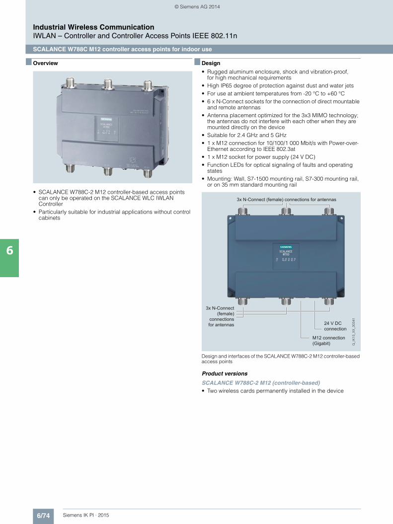
6/74 Siemens IK PI · 2015
Industrial Wireless CommunicationIWLAN – Controller and Controller Access Points IEEE 802.11n
SCALANCE W788C M12 controller access points for indoor use
6
■ Overview
• SCALANCE W788C-2 M12 controller-based access points can only be operated on the SCALANCE WLC IWLAN Controller
• Particularly suitable for industrial applications without control cabinets
■ Design
• Rugged aluminum enclosure, shock and vibration-proof, for high mechanical requirements
• High IP65 degree of protection against dust and water jets• For use at ambient temperatures from -20 °C to +60 °C• 6 x N-Connect sockets for the connection of direct mountable
and remote antennas • Antenna placement optimized for the 3x3 MIMO technology;
the antennas do not interfere with each other when they are mounted directly on the device
• Suitable for 2.4 GHz and 5 GHz• 1 x M12 connection for 10/100/1 000 Mbit/s with Power-over-
Ethernet according to IEEE 802.3at• 1 x M12 socket for power supply (24 V DC)• Function LEDs for optical signaling of faults and operating
states• Mounting: Wall, S7-1500 mounting rail, S7-300 mounting rail,
or on 35 mm standard mounting rail
Design and interfaces of the SCALANCE W788C-2 M12 controller-based access points
Product versions
SCALANCE W788C-2 M12 (controller-based)• Two wireless cards permanently installed in the device
3x N-Connect (female) connections for antennas
3x N-Connect (female)
connections for antennas 24 V DC
connection
M12 connection (Gigabit)
Kap_06_IWC_en.book Seite 74 Dienstag, 7. Oktober 2014 1:47 13
© Siemens AG 2014
6/75Siemens IK PI · 2015
Industrial Wireless CommunicationIWLAN – Controller and Controller Access Points IEEE 802.11n
SCALANCE W788C M12 controller access points for indoor use
6
■ Technical specifications
Article No. 6GK5788-2GD00-1AA0
Product-type designation SCALANCE W788C-2 M12
Transmission rate
Transmission rate• with W-LAN maximum 450 Mbit/s• with Industrial Ethernet 10 … 1 000 Mbit/s• note -
Interfaces
Number of electrical connections• for network components and
terminal equipment1
• for power supply 1• for redundant power supply 1
Design of electrical connection• for network components and
terminal equipmentM12 interface (8-pole, X-coded) PoE
• for power supply M12 interface (4-pole, A-coded) PoE
Number of optical interfaces for optical waveguide at 100 Mbit/s
-
Design of optical interfacefor optical waveguide at 100 Mbit/s
-
design of the removable storage C-PLUG
No
Interfaces wireless
Number of radio cards permanently installed
2
Number of internal antennas -
Number of electrical connectionsfor external antenna(s)
6
Design of the electrical connection for external antenna(s)
N-Connect (socket)
Product property external antenna can be mounted directly on device
Yes
Supply voltage, current consumption, power loss
Type of supply voltage DC
Supply voltage• 1 from M12 Power Connector (A-
coded) for redundant power supply19.2 V
• 2 from M12 Power Connector (A-coded) for redundant power supply
28.8 V
• from Power-over-Ethernet according IEEE802.3at for type 1 and IEEE802.3af
48 V
• from Power-over-Ethernet according IEEE802.3at for type 2
50 V
Current consumed• at 24 V with DC typical 0.63 A• with Power-over-Ethernet according
to IEEE802.3at for type 1 and IEEE802.3af typical
0.22 A
• with Power-over-Ethernet according to IEEE802.3at for type 2 typical
0.3 A
Effective power loss• at 24V for DC typical 15 W• with Power-over-Ethernet according
to IEEE802.3at for type 1 and IEEE802.3af typical
10.7 W
• with Power-over-Ethernet according to IEEE802.3at for type 2 typical
15 W
Permitted ambient conditions
Ambient temperature• during operating -20 … +60 °C• during storage -40 … +70 °C• during transport -40 … +70 °C
Relative humidity at 25 °C without condensation during operating maximum
90 %
Protection class IP IP65
Ambient condition for (standard) operation mode
When used under hazardous conditions (Zone 2), the SCALANCE W788-xPRO/RR or W74x-1PRO/RR product must be installed in an enclosure. To comply with EN 50021, this enclosure must meet the requirements of at least IP54 in compliance with EN 60529.
Article No. 6GK5788-2GD00-1AA0
Product-type designation SCALANCE W788C-2 M12
Kap_06_IWC_en.book Seite 75 Dienstag, 7. Oktober 2014 1:47 13
© Siemens AG 2014

6/76 Siemens IK PI · 2015
6
■ Technical specifications (continued)
Industrial Wireless CommunicationIWLAN – Controller and Controller Access Points IEEE 802.11n
SCALANCE W788C M12 controller access points for indoor use
Design, dimensions and weight
Width of enclosure without antenna 200 mm
Height of enclosure without antenna 176 mm
Depth of enclosure without antenna 79 mm
Net weight 1.7 kg
Mounting type wall mounting Yes
Wireless frequencies
Radio frequency• for WLAN in 2.4 GHz
frequency band2.41 … 2.48 GHz
• for WLAN in 5 GHzfrequency band
4.9 … 5.8 GHz
Product properties, functions, components general
Product function• Access Point Mode Yes• Client Mode No
Number of SSIDs 16
Product functions management, configuration
Product function• operation with IWLAN controller Yes• operation with Enterasys WLAN
controllerYes
Article No. 6GK5788-2GD00-1AA0
Product-type designation SCALANCE W788C-2 M12
Standards, specifications, approvals
Standard• for hazardous zone EN 60079-15:2005, EN 60079-
0:2006, II 3 G Ex nA II T4 KEMA 07 ATEX 0145X
• for safety of CSA and UL UL 60950-1 CSA C22.2 No. 60950-1
Verification of suitability• CE mark Yes• EC declaration of conformity Yes• C-Tick Yes• Railway application
in accordance with EN 50155No
• e1 approval No• E1 approval No• NEMA4X No• Power-over-Ethernet
according IEEE802.3at for type 1 and IEEE802.3af
Yes
• Power-over-Ethernet • according to IEEE802.3at for type 2
Yes
Standard for wireless communication• IEEE 802.11a Yes• IEEE 802.11b Yes• IEEE 802.11g Yes• IEEE 802.11h Yes• IEEE 802.11n Yes
Wireless approval You will find the current list of countries at: www.siemens.com/wireless-approvals
Accessories
Accessories -
Article No. 6GK5788-2GD00-1AA0
Product-type designation SCALANCE W788C-2 M12
Kap_06_IWC_en.book Seite 76 Dienstag, 7. Oktober 2014 1:47 13
© Siemens AG 2014
6/77Siemens IK PI · 2015
Industrial Wireless CommunicationIWLAN – Controller and Controller Access Points IEEE 802.11n
SCALANCE W788C M12 controller access points for indoor use
6
■ Ordering data Article No. ■ More information
Selection tools:
To assist in selecting Industrial Ethernet components, the TIA Selection Tool is available at:http://www.siemens.com/tia-selection-tool
Wireless approvals:
Current approvals can be found on the Internet at: http://www.siemens.com/wireless-approvals
SCALANCE W788C M12 Controller Access Points
IWLAN access pointsfor operating with the SCALANCE WLC IWLAN Controller; with two built-in wireless interfaces; wireless networksIEEE 802.11a/b/g/h/n at 2.4/5 GHz up to 450 Mbit/s; WPA2/AES; Power over Ethernet (PoE), IP65 degree of protection(-20 °C to +60 °C); scope of delivery: Mounting hardware; manual on CD-ROM, German/English• SCALANCE W788C-2 M12
with N-Connect female connec-tions for six external antennas
6GK5788-2GD00-1AA0
Accessories
IE FC M12 Plug PRO 4 x 2
M12 plug-in connector suitablefor on-site assembly (X-coded, IP65/IP67), metal enclosure, insulation/displacement fast con-nection method, for SCALANCE W• 1 unit 6GK1901-0DB30-6AA0• 8 units 6GK1901-0DB30-6AA8
DIN rail mounting adapter 6GK5798-8ML00-0AB3
DIN rail mounting adapter for SCALANCE W788 M12 and SCALANCE W788 RJ45; screw fixing for mounting on a 35 mm DIN rail to EN 50 022; scope of supply: 3 units per pack
IE FC Standard Cable GP 4 x 2 6XV1878-2A
8-core, shielded TP installation cable for connection to IE FC RJ45 Plug 4 x 2 and IE M12 Plug PRO 4 x 2; PROFINET-compatible; with UL approval; sold by the meter; max. length 1 000 m, minimum order quantity 20 m
IE FC Flexible Cable GP 4 x 2 6XV1878-2B
8-core, shielded TP installation cable for connection to IE FC RJ45 Plug 4 x 2 andIE M12 Plug PRO 4 x 2 for occasional movement; PROFINET-compliant; with UL approval; sold by the meter; max. length 1 000 m, minimum order 20 m
IE FC Stripping Tool 6GK1901-1GA00
Preadjusted stripping tool for fast stripping of the Industrial Ethernet FC cables
Power M12 Cable Connector PRO 6GK1907-0DC10-6AA3
Terminal socket for connection of SCALANCE W700 for 24 V DC supply voltage;4-pole, A-coded, with assembly instructions, 3 units
Power Cable 2 x 0.75 6XV1812-8A
Connecting cable for Power M12 Cable Connector PRO, sold by the meter
Antennas and miscellaneous IWLAN accessories
See Industrial Wireless LAN/accessories
Kap_06_IWC_en.book Seite 77 Dienstag, 7. Oktober 2014 1:47 13
© Siemens AG 2014
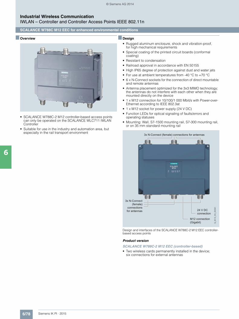
6/78 Siemens IK PI · 2015
Industrial Wireless CommunicationIWLAN – Controller and Controller Access Points IEEE 802.11n
SCALANCE W788C M12 EEC for enhanced environmental conditions
6
■ Overview
• SCALANCE W788C-2 M12 controller-based access points can only be operated on the SCALANCE WLC711 IWLAN Controller
• Suitable for use in the industry and automation area, but especially in the rail transport environment
■ Design
• Rugged aluminum enclosure, shock and vibration-proof, for high mechanical requirements
• Special coating of the printed circuit boards (conformal coating)
• Resistant to condensation • Railroad approval in accordance with EN 50155• High IP65 degree of protection against dust and water jets• For use at ambient temperatures from -40 °C to +70 °C• 6 x N-Connect sockets for the connection of direct mountable
and remote antennas• Antenna placement optimized for the 3x3 MIMO technology;
the antennas do not interfere with each other when they are mounted directly on the device
• 1 x M12 connection for 10/100/1 000 Mbit/s with Power-over-Ethernet according to IEEE 802.3at
• 1 x M12 socket for power supply (24 V DC)• Function LEDs for optical signaling of faults/errors and
operating statuses• Mounting: Wall, S7-1500 mounting rail, S7-300 mounting rail,
or on 35 mm standard mounting rail
Design and interfaces of the SCALANCE W788C-2 M12 EEC controller-based access points
Product version
SCALANCE W788C-2 M12 EEC (controller-based)• Two wireless cards permanently installed in the device;
six connections for external antennas
3x N-Connect (female) connections for antennas
3x N-Connect (female)
connections for antennas 24 V DC
connection
M12 connection (Gigabit)
Kap_06_IWC_en.book Seite 78 Dienstag, 7. Oktober 2014 1:47 13
© Siemens AG 2014

6/79Siemens IK PI · 2015
Industrial Wireless CommunicationIWLAN – Controller and Controller Access Points IEEE 802.11n
SCALANCE W788C M12 EEC for enhanced environmental conditions
6
■ Integration
Data transfer on trains using SCALANCE Controller-based access points
SCALANCE XR324-12M TS
with M12 module
SCALANCE W788C-2 M12 EEC
ANT 795-6MN
ANT 795-6MN
TunnelTunnel
ANT793-8DJ ANT793-8DJ ANT793-8DJ ANT793-8DJ
SCALANCE W788C-2 M12 EEC
Tunnel
G_I
K10_
XX
_303
30
SCALANCE W788C-2 M12 EEC
SCALANCE W788C-2 M12
EEC
SCALANCE X308-2M TS
SCALANCE XR552-12M
SCALANCE W788C-2 M12 EEC
Industrial Ethernet (Trainside)
Industrial Ethernet (Trainside)
Industrial Ethernet (Trackside)Communication Server
TrainguardTrain Control
Infotainment Server
Content Workstation
Workstations
WLAN Controller
Kap_06_IWC_en.book Seite 79 Dienstag, 7. Oktober 2014 1:47 13
© Siemens AG 2014

6/80 Siemens IK PI · 2015
Industrial Wireless CommunicationIWLAN – Controller and Controller Access Points IEEE 802.11n
SCALANCE W788C M12 EEC for enhanced environmental conditions
6
■ Technical specifications
Article No. 6GK5788-2GD00-1TA0
Product-type designation SCALANCE W788C-2 M12 EEC
Transmission rate
Transmission rate• with W-LAN maximum 450 Mbit/s• with Industrial Ethernet 10 … 1 000 Mbit/s• note -
Interfaces
Number of electrical connections• for network components
and terminal equipment1
• for power supply 1• for redundant power supply 1
Design of the electrical connection• for network components and
terminal equipmentM12 interface (8-pole, X-coded) PoE
• for power supply M12 interface (4-pole, A-coded)
Number of optical interfaces for optical waveguide at 100 Mbit/s
-
Design of optical interfacefor optical waveguide at 100 Mbit/s
-
Design of the removable storage C-PLUG
No
Interfaces wireless
Number of radio cards permanently installed
2
Number of internal antennas -
Number of electrical connectionsfor external antenna(s)
6
Design of the electrical connectionfor external antenna(s)
N-Connect (socket)
Product property external antenna can be mounted directly on device
Yes
Supply voltage, current consump-tion, power loss
Type of supply voltage DC
Supply voltage• 1 from M12 Power Connector
(A-coded) for redundant power supply
19.2 V
• 2 from M12 Power Connector (A-coded) for redundant power supply
28.8 V
• from Power-over-Ethernet according IEEE802.3at for type 1 and IEEE802.3af
48 V
• from Power-over-Ethernetaccording IEEE802.3at for type 2
50 V
Current consumed• at 24 V with DC typical 0.63 A• with Power-over-Ethernet
according to IEEE802.3at for type 1 and IEEE802.3af typical
0.22 A
• with Power-over-Ethernet according to IEEE802.3atfor type 2 typical
0.3 A
Effective power loss• at 24V for DC typical 15 W• with Power-over-Ethernet
according to IEEE802.3at for type 1 and IEEE802.3af typical
10.7 W
• with Power-over-Ethernet according to IEEE802.3atfor type 2 typical
15 W
Article No. 6GK5788-2GD00-1TA0
Product-type designation SCALANCE W788C-2 M12 EEC
Kap_06_IWC_en.book Seite 80 Dienstag, 7. Oktober 2014 1:47 13
© Siemens AG 2014
6/81Siemens IK PI · 2015
6
■ Technical specifications (continued)
Industrial Wireless CommunicationIWLAN – Controller and Controller Access Points IEEE 802.11n
SCALANCE W788C M12 EEC for enhanced environmental conditions
Permitted ambient conditions
Ambient temperature• during operating -20 … +60 °C• during storage -40 … +70 °C• during transport -40 … +70 °C
Relative humidity at 25 °C without condensation during operating maximum
90 %
Protection class IP IP65
Ambient condition for (standard) operation mode
When used under hazardous condi-tions (Zone 2), the SCALANCE W788-xPRO/RR or W74x-1PRO/RR product must be installed in an enclosure. To comply with EN 50021, this enclosure must meet the requirements of at least IP 54 in compliance with EN 60529.
Design, dimensions and weight
Width of enclosure without antenna 200 mmHeight of enclosure without antenna 176 mmDepth of enclosure without antenna 79 mm
Net weight 1.7 kg
Mounting type wall mounting Yes
Wireless frequencies
Radio frequency• for WLAN in 2.4 GHz
frequency band2.41 … 2.48 GHz
• for WLAN in 5 GHzfrequency band
4.9 … 5.8 GHz
Product properties, functions, components general
Product function• Access Point Mode Yes• Client Mode No
Number of SSIDs 16
Article No. 6GK5788-2GD00-1TA0
Product-type designation SCALANCE W788C-2 M12 EEC
Product functions management, configuration• operation with IWLAN controller Yes• operation with Enterasys WLAN
controllerYes
Standards, specifications, approvals
Standard• for EMC from FM FM 3611: Class I, Division 2,
Groups A,B,C,D, T4 / Class 1, Zone 2, Group IIC, T4
• for hazardous zone -• for safety of CSA and UL UL 60950-1 CSA C22.2 No. 60950-1
Verification of suitability• CE mark Yes• EC declaration of conformity Yes• C-Tick Yes• CCC -• Railway application in accordance
with EN 50155Yes
• e1 approval No• E1 approval No• NEMA4X No• Power-over-Ethernet according
IEEE802.3at for type 1 and IEEE802.3af
Yes
• Power-over-Ethernet according to IEEE802.3at for type 2
Yes
Standard for wireless communication• IEEE 802.11a Yes• IEEE 802.11b Yes• IEEE 802.11e Yes• IEEE 802.11g Yes• IEEE 802.11h Yes• IEEE 802.11i Yes• IEEE 802.11n Yes
Wireless approval You will find the current list of countries at: www.siemens.com/wireless-approvals
Accessories
Accessories -
Article No. 6GK5788-2GD00-1TA0
Product-type designation SCALANCE W788C-2 M12 EEC
Kap_06_IWC_en.book Seite 81 Dienstag, 7. Oktober 2014 1:47 13
© Siemens AG 2014

6/82 Siemens IK PI · 2015
Industrial Wireless CommunicationIWLAN – Controller and Controller Access Points IEEE 802.11n
SCALANCE W788C M12 EEC for enhanced environmental conditions
6
■ Ordering data Article No. ■ More information
Selection tools:
To assist in selecting Industrial Ethernet components, the TIA Selection Tool is available at:http://www.siemens.com/tia-selection-tool
Wireless approvals:
Current approvals can be found on the Internet at: http://www.siemens.com/wireless-approvals
SCALANCE W788C M12 EEC Controller Access Points
IWLAN access pointsfor operation with the SCALANCE WLC IWLAN controller; with built-in wireless interfaces; wireless networks IEEE 802.11a/b/g/h/n at 2.4/5 GHz up to 450 Mbit/s; railroad approval in accordance with EN 50155; conformal coating; WPA2/AES; Power over Ethernet (PoE),IP65 degree of protection; scope of supply: Mounting hardware; manualon CD-ROM, German/English• SCALANCE W788C-2 M12 EEC
with N-Connect female connec-tions for six external antennas
6GK5788-2GD00-1TA0
Accessories
IE FC M12 Plug PRO 4 x 2
M12 plug-in connector suitable for on-site assembly (X-coded, IP65/IP67), metal enclosure, insulation displacement fast con-nection method, for SCALANCE W• 1 unit 6GK1901-0DB30-6AA0• 2 units 6GK1901-0DB30-6AA8
DIN rail mounting adapter 6GK5798-8ML00-0AB3
DIN rail mounting adapter for SCALANCE W788 M12 and SCALANCE W788 RJ45; screw fixing for mounting on a 35 mm DIN rail to EN 50 022; scope of supply: 3 units per pack
IE FC standard cable GP 4 x 2 6XV1878-2A
8-core, shielded TP installation cable for connection to IE FC RJ45 Plug 4 x 2 and IE M12 Plug PRO 4 x 2; PROFINET-compliant; with UL approval; sold by the meter; max. length 1 000 m, minimum order quantity 20 m
IE FC flexible cable GP 4 x 2 6XV1878-2B
8-core, shielded TP installation cable for connection to IE FC RJ45 Plug 4 x 2 and IE M12 Plug PRO 4 x 2 for occa-sional movement; PROFINET-compliant; with UL approval; sold by the meter; max. length 1 000 m,minimum order 20 m
IE FC Stripping Tool 6GK1901-1GA00
Preadjusted stripping tool for fast stripping of the Industrial Ethernet FC cables
Power M12 cable connector PRO 6GK1907-0DC10-6AA3
Terminal socket for connection of SCALANCE W700 for 24 V DC supply voltage; 4-pole, A-coded, with assembly instructions, 3 units
Power Cable 2 x 0.75 6XV1812-8A
Connecting cable for Power M12 cable connector PRO, sold by the meter
Antennas and miscellaneous IWLAN accessories
See Industrial Wireless LAN/accessories
Kap_06_IWC_en.book Seite 82 Dienstag, 7. Oktober 2014 1:47 13
© Siemens AG 2014

6/83Siemens IK PI · 2015
Industrial Wireless CommunicationIWLAN – Controller and Controller Access Points IEEE 802.11n
SCALANCE W786 RJ45 controller access points for outdoor use
6
■ Overview
• SCALANCE W786C-2 controller-based access points can only be operated on the SCALANCE WLC IWLAN Controller
• Particularly well-suited to applications with demanding climatic requirements when installed outdoors and in areas accessible to the public
■ Design
• Rugged, impact-resistant plastic enclosure, shock and vibration-proof for demanding mechanical requirements
• High IP65 degree of protection against dust and water jets• For use at ambient temperatures from -40 °C to +60 °C• Resistant to condensation • Resistant to UV radiation and saltwater spray• Design for use outdoors• 6 x R-SMA sockets for the connection of remote antennas• Suitable for 2.4 GHz and 5 GHz• 1 x RJ45 connector for 10/100/1 000 Mbit/s and Power-over-
Ethernet according to IEEE 802.3at • 1 x 24 V DC connector, optional operation with 12 to 24 V DC
or 100 to 240 V AC with power supply that can be integrated in the device
• Function LEDs for optical signaling of faults and operating states
• Mounting: Wall or, with optional mounting set, on S7 mounting rail, 35 mm standard mounting rail, or on a pole
Design and interfaces of the SCALANCE W786C-2 controller-based access points
Product versions
SCALANCE W786C-2 RJ45 (controller-based)• Two wireless cards permanently installed in the device;
six connections for external antennas
SCALANCE W786C-2IA RJ45 (controller-based)• Two wireless cards permanently installed in the device;
six internal antennas
Infeed of 24 V DC or with power supplies 100-240 V AC or12-24 V DC (redundant)
Internal antennas depending on variant
6 x antennaconnections R-SMA (female) dependingon variant
RJ45 connection (Gigabit)
Kap_06_IWC_en.book Seite 83 Dienstag, 7. Oktober 2014 1:47 13
© Siemens AG 2014
6/84 Siemens IK PI · 2015
Industrial Wireless CommunicationIWLAN – Controller and Controller Access Points IEEE 802.11n
SCALANCE W786 RJ45 controller access points for outdoor use
6
■ Technical specifications
Article No. 6GK5786-2HC00-1AA0 6GK5 786-2FC00-1AA0
Product-type designation SCALANCE W786C-2IA RJ45 SCALANCE W786C-2 RJ45
Transmission rate
Transmission rate• with W-LAN maximum 450 Mbit/s 450 Mbit/s• with Industrial Ethernet 10 … 1 000 Mbit/s 10 … 1 000 Mbit/s• note - -
Interfaces
Number of electrical connections• for network components
and terminal equipment1 1
• for power supply 1 1• for redundant power supply 1 1
Design of electrical connection• for network components
and terminal equipmentRJ45 socket RJ45 socket
• for power supply 2-pole connector (24 V DC) or optionally available power supply adapter (4-pole 24 V DC or 3-pole 110 to 230 V AC)
2-pole connector (24 V DC) or optionally available power supply adapter (4-pole 24 V DC or 3-pole 110 to 230 V AC)
Number of optical interfacesfor optical waveguide at 100 Mbit/s
- -
Design of optical interface for optical waveguide at 100 Mbit/s
- -
Number of optical interfacesfor optical waveguide at 1 000 Mbit/s
- -
Design of optical interfacefor optical waveguide at 1 000 Mbit/s
- -
Design of the removable storage C-PLUG
No No
Interfaces wireless
Number of radio cards permanently installed
2 2
Number of internal antennas 6 -
Number of electrical connectionsfor external antenna(s)
- 6
Design of the electrical connectionfor external antenna(s)
- R-SMA (socket)
Product property external antenna can be mounted directly on device
- No
Supply voltage, current consumption, power loss
Type of supply voltage DC DC
Supply voltage• 1 from terminal block 19.2 V 19.2 V• 2 from terminal block 28.8 V 28.8 V• from Power-over-Ethernet
according IEEE802.3at for type 1 and IEEE802.3af
48 V 48 V
• from Power-over-Ethernet according IEEE802.3at for type 2
50 V 50 V
• from optional integratable power supply- with AC 100 … 240 V 100 … 240 V- with DC 12 … 24 V 12 … 24 V
Current consumed• at 24 V with DC typical 0.63 A 0.63 A• at 230 V with AC typical 0.07 A 0.07 A• with Power-over-Ethernet
according to IEEE802.3at for type 1 and IEEE802.3af typical
0.22 A 0.22 A
• with Power-over-Ethernet according to IEEE802.3at for type 2 typical
- -
Kap_06_IWC_en.book Seite 84 Dienstag, 7. Oktober 2014 1:47 13
© Siemens AG 2014
6/85Siemens IK PI · 2015
6
■ Technical specifications (continued)
Industrial Wireless CommunicationIWLAN – Controller and Controller Access Points IEEE 802.11n
SCALANCE W786 RJ45 controller access points for outdoor use
Effective power loss• at 24V for DC typical 15 W 15 W• at 230 V with AC typical 15 W 15 W• with Power-over-Ethernet
according to IEEE802.3at for type 1 and IEEE802.3af typical
15 W 10.7 W
• with Power-over-Ethernet according to IEEE802.3at for type 2 typical
- -
Permitted ambient conditions
Ambient temperature• during operating -40 … +60 °C -40 … +60 °C• during storage -40 … +85 °C -40 … +85 °C• during transport -40 … +85 °C -40 … +85 °C
Relative humidity at 25 °C without condensation during operating maximum
100 % 100 %
Protection class IP IP65 IP65
Ambient condition for (standard) operation mode
When using the power supply 100 to 240 V AC, an operating temperature of -40 °C to +60 °Cis permissible
When using the power supply 100 to 240 V AC, an operating temperature of -40 °C to +60 °C is permissible
Design, dimensions and weight
Width of enclosure without antenna 251 mm 251 mm
Height of enclosure without antenna 251 mm 251 mm
Depth of enclosure without antenna 72 mm 72 mm
Net weight 2.24 kg 2.24 kg
Mounting type wall mounting Yes Yes
Mounting type For mast mounting, 35 mm DIN rail mounting and S7-300 rail mounting, an additional support plate is required
For mast mounting, 35 mm DIN rail mounting and S7-300 rail mounting, an additional support plate is required
Wireless frequencies
Radio frequency• for WLAN in 2.4 GHz
frequency band2.41 … 2.48 GHz 2.41 … 2.48 GHz
• for WLAN in 5 GHzfrequency band
4.9 … 5.8 GHz 4.9 … 5.8 GHz
Product properties, functions,components general
Product function• Access Point Mode Yes Yes• Client Mode No No
Number of SSIDs 16 16
Product functions management, configuration
Product function• operation with IWLAN controller Yes Yes• operation with Enterasys WLAN
controllerYes Yes
Article No. 6GK5786-2HC00-1AA0 6GK5 786-2FC00-1AA0
Product-type designation SCALANCE W786C-2IA RJ45 SCALANCE W786C-2 RJ45
Kap_06_IWC_en.book Seite 85 Dienstag, 7. Oktober 2014 1:47 13
© Siemens AG 2014

6/86 Siemens IK PI · 2015
6
■ Technical specifications (continued)
Industrial Wireless CommunicationIWLAN – Controller and Controller Access Points IEEE 802.11n
SCALANCE W786 RJ45 controller access points for outdoor use
Standards, specifications, approvals
Standard• for hazardous zone EN 60079-15:2005, EN 60079-0:2006, II 3 G Ex nA II T4
KEMA 07 ATEX 0145XEN 60079-15:2005, EN 60079-0:2006, II 3 G Ex nA II T4 KEMA 07 ATEX 0145X
• for safety of CSA and UL UL 60950-1 CSA C22.2 No. 60950-1 UL 60950-1 CSA C22.2 No. 60950-1
Verification of suitability• CE mark Yes Yes• EC declaration of conformity Yes Yes• C-Tick Yes Yes• CCC No No• Railway application
in accordance with EN 50155No No
• e1 approval• E1 approval No No• NEMA4X Yes Yes• Power-over-Ethernet according
IEEE802.3at for type 1 and IEEE802.3af
Yes Yes
• Power-over-Ethernet according to IEEE802.3at for type 2
Yes Yes
Standard for wireless communication• IEEE 802.11a Yes Yes• IEEE 802.11b Yes Yes• IEEE 802.11g Yes Yes• IEEE 802.11h Yes Yes• IEEE 802.11n Yes Yes
Wireless approval You will find the current list of countries at: www.siemens.com/wireless-approvals
You will find the current list of countries at: www.siemens.com/wireless-approvals
Accessories
Accessories 24 V DC screw terminal included in scope of delivery 24 V DC screw terminal included in scope of delivery
Article No. 6GK5786-2HC00-1AA0 6GK5 786-2FC00-1AA0
Product-type designation SCALANCE W786C-2IA RJ45 SCALANCE W786C-2 RJ45
Kap_06_IWC_en.book Seite 86 Dienstag, 7. Oktober 2014 1:47 13
© Siemens AG 2014

6/87Siemens IK PI · 2015
Industrial Wireless CommunicationIWLAN – Controller and Controller Access Points IEEE 802.11n
SCALANCE W786 RJ45 controller access points for outdoor use
6
■ Ordering data Article No. ■ More information
Selection tools:
To assist in selecting Industrial Ethernet components, the TIA Selection Tool is available at:http://www.siemens.com/tia-selection-tool
Wireless approvals:
Current approvals can be found on the Internet at: http://www.siemens.com/wireless-approvals
SCALANCE W786C Controller access points
IWLAN access points for operating with the SCALANCE WLC IWLAN Controller; with two built-in wireless interfaces; wireless networks IEEE 802.11a/b/g/h/n at 2.4/5 GHz up to 450 Mbit/s; WPA2/AES;Power over Ethernet (PoE),IP65 degree of protection (-40 °C to +60 °C); scope of delivery: Mounting hardware, 2-pin screw terminal for 24 V DC; manual on CD-ROM; German/English• SCALANCE W786C-2IA RJ45
with six internal antennas6GK5786-2HC00-1AA0
• SCALANCE W786C-2 RJ45with R-SMA female connections for six external antennas
6GK5786-2FC00-1AA0
Accessories
Power supply PS791-2DC 6GK5791-2DC00-0AA0
12 to 24 V DC power supply for installation in SCALANCE W786C-2 products; operating instructionsin German/English
Power supply PS791-2AC 6GK5791-2AC00-0AA0
110 to 230 V DC power supply for installation in SCALANCE W786C-2 products; operating instructionsin German/English
MS1 mounting set 6GK5798-8MG00-0AA0
Mounting set for fixing the SCALANCE W786C-2 products onto an S7-300 mounting rail or a 35 mm standard mounting rail
IE FC RJ-45 Plug 4 x 2
RJ45 plug connector for Industrial Ethernet (10/100/1 000 Mbit/s) with a rugged metal enclosure and integrated insulation displacement contacts for connecting Industrial Ethernet FC installation cables; 180° cable outlet; for network components and CPs/CPUs with Industrial Ethernet interface• 1 pack = 1 unit 6GK1901-1BB11-2AA0• 1 pack = 10 units 6GK1901-1BB11-2AB0• 1 pack = 50 units 6GK1901-1BB11-2AE0
IE FC Standard Cable GP 4 x 2 6XV1878-2A
8-core, shielded TP installation cable for connection toIE FC RJ45 Plug 4 x 2 andIE M12 Plug PRO 4 x 2; PROFINET-compatible; with UL approval; sold by the meter; max. length 1 000 m, minimum order quantity 20 m
IE FC Stripping Tool 6GK1901-1GA00
Preadjusted stripping toolfor fast stripping of the Industrial Ethernet FC cables
Antennas and miscellaneous IWLAN accessories
See Industrial Wireless LAN/accessories
Kap_06_IWC_en.book Seite 87 Dienstag, 7. Oktober 2014 1:47 13
© Siemens AG 2014
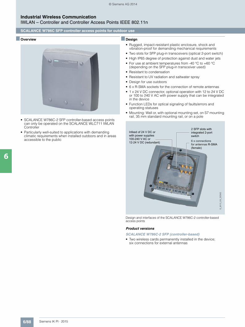
6/88 Siemens IK PI · 2015
Industrial Wireless CommunicationIWLAN – Controller and Controller Access Points IEEE 802.11n
SCALANCE W786C SFP controller access points for outdoor use
6
■ Overview
• SCALANCE W786C-2 SFP controller-based access points can only be operated on the SCALANCE WLC711 IWLAN Controller
• Particularly well-suited to applications with demanding climatic requirements when installed outdoors and in areas accessible to the public
■ Design
• Rugged, impact-resistant plastic enclosure, shock and vibration-proof for demanding mechanical requirements
• Two slots for SFP plug-in transceivers (optical 2-port switch)• High IP65 degree of protection against dust and water jets• For use at ambient temperatures from -40 °C to +60 °C
(depending on the SFP plug-in transceiver used)• Resistant to condensation • Resistant to UV radiation and saltwater spray• Design for use outdoors• 6 x R-SMA sockets for the connection of remote antennas • 1 x 24 V DC connector, optional operation with 12 to 24 V DC
or 100 to 240 V AC with power supply that can be integrated in the device
• Function LEDs for optical signaling of faults/errors and operating statuses
• Mounting: Wall or, with optional mounting set, on S7 mounting rail, 35 mm standard mounting rail, or on a pole
Design and interfaces of the SCALANCE W786C-2 controller-based access points
Product versions
SCALANCE W786C-2 SFP (controller-based)• Two wireless cards permanently installed in the device;
six connections for external antennas
Infeed of 24 V DC or with power supplies 100-240 V AC or12-24 V DC (redundant) 6 x connections
for antennas R-SMA (female)
2 SFP slots with integrated 2-port switch
Kap_06_IWC_en.book Seite 88 Dienstag, 7. Oktober 2014 1:47 13
© Siemens AG 2014

6/89Siemens IK PI · 2015
Industrial Wireless CommunicationIWLAN – Controller and Controller Access Points IEEE 802.11n
SCALANCE W786C SFP controller access points for outdoor use
6
■ Technical specifications
Article No. 6GK5786-2FE00-1AA0
Product-type designation SCALANCE W786C-2 SFP
Transmission rate
Transfer rate• with W-LAN maximum 450 Mbit/s• with Industrial Ethernet 1 000 Mbit/s• note -
Interfaces
Number of electrical connections• for network components
and terminal equipment-
• for power supply 1• for redundant power supply 0
Design of the electrical connection• for network components
and terminal equipment-
• for power supply 2-pole connector (24 V DC) or optionally available power supply adapter (4-pole 24 V DC or 3-pole 110 to 230 V AC)
Number of optical interfaces for optical waveguide at 100 Mbit/s
2
Design of optical interface for optical waveguide at 100 Mbit/s
SFP slot
Number of optical interfaces for optical waveguide at 1000 Mbit/s
2
Design of optical interface for optical waveguide at 1000 Mbit/s
SFP slot
Design of the removable storage C-PLUG
No
Interfaces wireless
Number of radio cards permanently installed
2
Number of internal antennas -
Number of electrical connections for external antenna(s)
6
Design of the electrical connection for external antenna(s)
R-SMA (socket)
Product property external antenna can be mounted directly on device
No
Supply voltage, current consumption, power loss
Type of supply voltage DC
Supply voltage• 1 from terminal block 19.2 V• 2 from terminal block 28.8 V• from Power-over-Ethernet
according IEEE802.3at for type 1 and IEEE802.3af
-
• from Power-over-Ethernet according IEEE802.3at for type 2
-
• from optional integratable power supply- with AC 100 … 240 V- with DC 12 … 24 V
Current consumed• at 24 V with DC typical -• at 230 V with AC typical -• with Power-over-Ethernet
according to IEEE802.3at for type 1 and IEEE802.3af typical
-
• with Power-over-Ethernet according to IEEE802.3at for type 2 typical
-
Effective power loss• at 24V for DC typical -• at 230 V with AC typical -• with Power-over-Ethernet
according to IEEE802.3at for type 1 and IEEE802.3af typical
-
• with Power-over-Ethernet according to IEEE802.3at for type 2 typical
-
Article No. 6GK5786-2FE00-1AA0
Product-type designation SCALANCE W786C-2 SFP
Kap_06_IWC_en.book Seite 89 Dienstag, 7. Oktober 2014 1:47 13
© Siemens AG 2014

6/90 Siemens IK PI · 2015
6
■ Technical specifications (continued)
Industrial Wireless CommunicationIWLAN – Controller and Controller Access Points IEEE 802.11n
SCALANCE W786C SFP controller access points for outdoor use
Permitted ambient conditions
Ambient temperature• during operating -40 … +60 °C• during storage -40 … +85 °C• during transport -40 … +85 °C
Relative humidity at 25 °C without condensation during operating maximum
100 %
Protection class IP IP65
Ambient condition for (standard) operation mode
When using the power supply 100 to 240 V AC, an operating temperature of -40 °C to +60 °C is permissible
Design, dimensions and weight
Width of enclosure without antenna 251 mmHeight of enclosure without antenna 251 mmDepth of enclosure without antenna 72 mm
Net weight 2.24 kg
Mounting type wall mounting Yes
Mounting type For mast mounting, 35 mm DIN rail mounting and S7-300 rail mounting, an additional support plate is required
Wireless frequencies
Radio frequency• for WLAN in 2.4 GHz
frequency band2.41 … 2.48 GHz
• for WLAN in 5 GHzfrequency band
4.9 … 5.8 GHz
Product properties, functions, components general
Product function• Access Point Mode Yes• Client Mode No
Number of SSIDs 16
Product functions management, configuration
Product function• operation with IWLAN controller Yes• operation with Enterasys WLAN
controllerYes
Article No. 6GK5786-2FE00-1AA0
Product-type designation SCALANCE W786C-2 SFP
Standards, specifications, approvals
Standard• for EMC from FM FM 3611: Class I, Division 2,
Groups A,B,C,D, T4 / Class 1, Zone 2, Group IIC, T4
• for hazardous zone EN 60079-15:2005, EN 60079-0:2006, II 3 G Ex nA II T4 KEMA 07 ATEX 0145X
• for safety of CSA and UL UL 60950-1 CSA C22.2 No. 60950-1
Verification of suitability• CE mark Yes• EC declaration of conformity Yes• C-Tick Yes• CCC No• Railway application in accordance
with EN 50155No
• e1 approval• E1 approval No• NEMA4X Yes• Power-over-Ethernet according
IEEE802.3at for type 1 and IEEE802.3af
No
• Power-over-Ethernet according to IEEE802.3at for type 2
No
Standard for wireless communication• IEEE 802.11a Yes• IEEE 802.11b Yes• IEEE 802.11g Yes• IEEE 802.11h Yes• IEEE 802.11n Yes
Wireless approval You will find the current list of countries at: www.siemens.com/wireless-approvals
Accessories
Accessories 24 V DC screw terminal included in scope of delivery
Article No. 6GK5786-2FE00-1AA0
Product-type designation SCALANCE W786C-2 SFP
Kap_06_IWC_en.book Seite 90 Dienstag, 7. Oktober 2014 1:47 13
© Siemens AG 2014

6/91Siemens IK PI · 2015
Industrial Wireless CommunicationIWLAN – Controller and Controller Access Points IEEE 802.11n
SCALANCE W786C SFP controller access points for outdoor use
6
■ Ordering data Article No. ■ More information
Selection tools:
To assist in selecting Industrial Ethernet components, the TIA Selection Tool is available at:
http://www.siemens.com/tia-selection-tool
Wireless approvals:
Current approvals can be found on the Internet at: http://www.siemens.com/wireless-approvals
SCALANCE W786C-2 SFP controller access points
IWLAN access pointsfor operating with theSCALANCE WLC IWLAN Controller; with two built-in wireless interfaces and one integral 2-port switch (SFP slots); wireless networksIEEE 802.11a/b/g/h/n at 2.4/5 GHz up to 450 Mbit/s; WPA2/AES;IP65 degree of protection (-40 °C to +60 °C); scope of delivery: Mounting hardware, 2-pin screw terminal for 24 V DC; manual on CD-ROM; German/English• SCALANCE W786C-2 SFP
with six internal antennas6GK5786-2FE00-1AA0
Accessories
Power supply PS791-2DC 6GK5791-2DC00-0AA0
12 to 24 V DC power supply for installation in SCALANCE W786C-2 products; operating instructionsin German/English
Power supply PS791-2AC 6GK5791-2AC00-0AA0
110 to 230 V DC power supply for installation in SCALANCE W786C-2 products; operating instructions in German/English
MS1 mounting set 6GK5798-8MG00-0AA0
Mounting set for fixing the SCALANCE W786C-2 products onto an S7-300 mounting rail or a 35 mm standard mounting rail
Antennas and miscellaneous IWLAN accessories
See Industrial Wireless LAN/accessories
SFP plug-in transceiver
SFP992-1 6GK5992-1AL00-8AA0
Gigabit, multimode, 750 m
SFP992-1LD 6GK5992-1AM00-8AA0
Gigabit, singlemode, 10 km
SFP992-1LH 6GK5992-1AN00-8AA0
Gigabit, singlemode, 40 km
SFP992-1LH+ 6GK5992-1AP00-8AA0
Gigabit, singlemode, 70 km
Fiber-optic cables See glass fiber-optic cables
Kap_06_IWC_en.book Seite 91 Dienstag, 7. Oktober 2014 1:47 13
© Siemens AG 2014

6/92 Siemens IK PI · 2015
Industrial Wireless CommunicationIWLAN – Client Modules IEEE 802.11n
Overview
6
■ Overview
The client modules from the SCALANCE W700 product lines are optimal for integrating Industrial Ethernet stations into Industrial Wireless LANs (IWLANs) for 2.4 GHz and 5 GHz. • High data rates (up to 450 Mbit/s in connection with Channel
Bonding) as per IEEE802.11n • Reliable wireless link by using of MIMO technology (Multiple
Input, Multiple Output). For this, SCALANCE W Client Modules use up to three streams for simultaneous sending and receiving.
• SCALANCE W700 Client Modules are suitable for any appli-cation: for installation indoors without a control cabinet and for installation in a control cabinet
• Reliable thanks to a rugged enclosure, protected from water and dust (up to IP65), resistant to shock, vibration and electro-magnetic fields
• Demanding applications with real-time and redundancy requirements, such as PROFINET with PROFIsafe
• Conformant to standards through supporting IEEE802.11; expanded software functions especially for use where increased reliability is required, e.g. cyclic real-time data traffic and very high-speed roaming (iPCF, iPCF-MC)
• Configuration support by means of wizards and online help; easy management via Web server and SNMP
• Configuration and diagnostics using Web based Management, Command Line Interface, and SNMP. Devices and networks can be configured using STEP 7 (TIA Portal). For cyclic monitoring, diagnostics and documentation (reporting) in network mode, the SINEMA Server software is recommended.
• Enabling of further functions using the KEY-PLUG swap medium (iPCF, iPCF-MC)
• Fast replacement of devices if a fault occurs thanks to use of optional KEY-PLUG/C-PLUG (Configuration Plug) swap medium
■ Benefits
• Predictable data traffic (deterministic response) and defined response times on the wireless link
• Reliable wireless link, e.g. by using MIMO technology and monitoring the wireless link
• Cost savings due to one single wireless network both for process-critical data and for non-critical communication
• Future-proof because all products are compatible with the internationally recognized WLAN standard IEEE 802.11, suitable for license-free 2.4 GHz and 5 GHz frequency bands (ISM bands)
• Implementation of data-intensive applications such as video streaming
• Reduced operating costs, because there is no wear and tear on rotating and moving plant sections
• Cost-effective connection to devices which are remote, difficult to access or installed in hostile environments
• Investment protection because flexible feature expansions (iFeatures) are possible by using the KEY-PLUG
Kap_06_IWC_en.book Seite 92 Dienstag, 7. Oktober 2014 1:47 13
© Siemens AG 2014

6/93Siemens IK PI · 2015
Industrial Wireless CommunicationIWLAN – Client Modules IEEE 802.11n
Overview
6
■ Application
The client modules of the SCALANCE W700 product line are designed for indoor and outdoor industrial applications as well as for low-cost integration in control cabinets or mobile ma-chines. They provide a reliable wireless link with fast handover from one access point to the next (roaming). This allows pro-cesses to be monitored and loss of production due to machine downtimes to be avoided. Industrial Wireless LAN (IWLAN) can also be used in time-critical applications in factory automation (PROFINET IO) or for safety-related signals (PROFIsafe).
SCALANCE W products are silicone-free and can therefore also be used in paint shops. The client modules with high IP65 degree of protection and extended temperature range from -20 to +60 °C are especially suitable for industrial applications.
The client modules are especially suitable for use in automated guided vehicle systems or suspended monorails.
When using the RCoax cable (radiating cable), operation is particularly reliable in conveyor systems and all track applica-tions (e.g. storage and retrieval systems, suspended monorail).
Application examples:• Automated guided vehicle systems and suspended
monorails; prevents wear and offers high flexibility for traffic routing thanks to the wireless transfer of data to the vehicles. It is also possible to transfer PROFIsafe via IWLAN.
• Cranes; high flexibility due to access to data communication with the moving unit independent of the location
• Tunnel application; reliable wireless link since the devices can handle multiple path propagation better by using the MIMO technology
• Communication with moving stations (e.g. mobile controls and devices), container logistics, storage and retrieval machines, conveyor systems, conveyor belts, rotating machines, trucks
• Wireless coupling of communication segments and bridging of large distances for fast commissioning and cost-effective networks in applications where cable routing would be extremely expensive (e.g. on public roads, rivers, lakes, train lines)
■ Function
SCALANCE W700 client modules make it possible for a node with an Industrial Ethernet interface (e.g. a controller) to move seamlessly and with no wear and tear in an Industrial Wireless LAN RF field. The node logs on in the RF field via the client mod-ule and can exchange information with the entire data network. If the client module moves, for example, on an automated guided vehicle system, it is automatically and transparently handed over from one access point to the next (roaming).
This is possible over distances of up to 30 m indoors (approx. 100 m outdoors). Additional directional antennas can be used outdoors to achieve ranges of several thousand meters.
Apart from a reliable wireless link, a major feature of the SCALANCE W700 client modules is their support of IT mecha-nisms: • IEEE 802.11a/b/g/n for different frequency ranges• IEEE802.11e for wireless multimedia (WMM)• IEEE802.11i for security• Sending the log entries of the SCALANCE W devices to a
Syslog server• Modern security mechanisms (e.g. network security such as
IEEE 802.1x, RADIUS, EAP mechanisms)
Security
A high degree of data security is achieved by means of the WPA2/IEEE 802.11i mechanisms. These define modern proce-dures that control a regular exchange of the complete 128-bit key as well as performing the access check (authentication) of a node. The Advanced Encryption Standard (AES) is available for data encryption.
On top of this, access to the devices (HTTPS) is encrypted and a secure logon (SSH) is possible. If a security concept in combi-nation with SCALANCE S is required, the security requirements can be increased using Virtual Private Networks (VPN).
Functional scope
Depending on the product version, the SCALANCE W700 client modules can manage the wireless connection for up to eight connected devices with Ethernet interface. It is possible for mobile units with a small Ethernet network (up to eight devices) to be linked into an IWLAN RF field.
Kap_06_IWC_en.book Seite 93 Dienstag, 7. Oktober 2014 1:47 13
© Siemens AG 2014

6/94 Siemens IK PI · 2015
6
■ Function (continued)
Industrial Wireless CommunicationIWLAN – Client Modules IEEE 802.11n
Overview
iFeatures (only in conjunction with KEY-PLUG or SCALANCE W722-1 RJ45))
iPCF (industrial Point Coordination Function): The iPCF mode is a good choice for applications with require-ments for real-time and predictable response times (determinis-tic response), even when mobile nodes are roaming from one access point to the next. This ensures that wireless PROFINET IO is supported and that safety-related signals, e.g. emergency stop, can be linked into the RF field.
The iPCF mechanism expands the IEEE 802.11 standard and must be available on both the client module and the access point. In an RF field in which iPCF is used, no IEEE 802.11-com-pliant nodes can be operated.
iPCF is recommended for applications where wireless network nodes move along predefined paths (e.g. suspended monorail). RCoax radiating cables or directional antennas must be used for this purpose.
Linking in an automated guided vehicle system using iPCF with the SCALANCE W722-1 RJ45
iPCF-MC (iPCF Management Channel) 1):iPCF-MC is available as a further development of iPCF. This mode should be used if IWLAN stations that also support iPCF-MC move freely about in the coverage area (especially when using omni-directional antennas) and are to exchange data deterministically. This functionality can only be achieved in connection with access points with two wireless interfaces and the KEY PLUG.
Note:
These iFeatures cannot be used in parallel.
Diagnostics and management• Web-based (HTTP/HTTPS) management tool for configuration
and diagnostics using a standard browser • LEDs for signaling operating status and fault/error states • Signaling of faults by means of SNMP trap or e-mail to a
network management tool• Configuration and diagnostics using Web based
Management, Command Line Interface, and SNMP. Devices and networks can be configured using STEP 7 (TIA Portal). For cyclic monitoring, diagnostics and documentation (reporting) in network mode, the SINEMA Server software is recommended.1) Available soon
RCoax Cable Segment 1 RCoax Cable Segment 2
Access PointSCALANCE
W784-1RR inthe cabinet
Access PointSCALANCEW784-1RR inthe cabinet
G_I
K10
_XX
_301
72IWLAN RCoax Cable IWLAN RCoax Cable
Client ModuleSCALANCE W722-1 RJ45
Panel PC
Client ModuleSCALANCE W722-1 RJ45
Panel PC
Client ModuleSCALANCE W722-1 RJ45
Panel PC
WinAC WinACWinAC
Kap_06_IWC_en.book Seite 94 Dienstag, 7. Oktober 2014 1:47 13
© Siemens AG 2014

6/95Siemens IK PI · 2015
Industrial Wireless CommunicationIWLAN – Client Modules IEEE 802.11n
SCALANCE W748 RJ45 for use in control cabinet
6
■ Overview
• Suitable for applications where the client module is to be mounted in the control cabinet
■ Design
• Rugged aluminum enclosure, shock and vibration-proof, for high mechanical requirements
• Dust protection with IP30 degree of protection• For use at ambient temperatures from -20 °C to +60 °C• 3 x R-SMA sockets for the connection of directly mountable
and remote antennas (6 x R-SMA sockets for the variants with two wireless modules)
• Antenna placement optimized for the 3x3 MIMO technology; the antennas do not interfere with each other when they are mounted directly on the device
• 1 x RJ45 connector for 10/100/1 000 Mbit/s with Power-over-Ethernet according to IEEE 802.3at
• 2 x 24 V DC connection for redundant energy supply• 1 x PLUG compartment for KEY-PLUG/C-PLUG• Function LEDs for optical signaling of faults/errors and
operating statuses• Digital input for feeding in a signal from a sensor, for example,
to an SNMP-based network management system• Digital output for converting a command received over SNMP
into a signal and switching a hardware function • Mounting: Wall, S7-1500 mounting rail, S7-300 mounting rail,
or on 35 mm standard mounting rail
Design and interfaces of the SCALANCE W748-1 RJ45 client modules
Product versions
SCALANCE W748-1 RJ45• A radio card is permanently installed; functional scope can be
expanded by using a KEY-PLUG W780 iFeatures
Terminal block for digital input/output
3x R-SMA (female) antenna connections
PLUG slot
24 V DC connection
RJ45 connection (Gigabit)
Kap_06_IWC_en.book Seite 95 Dienstag, 7. Oktober 2014 1:47 13
© Siemens AG 2014

6/96 Siemens IK PI · 2015
Industrial Wireless CommunicationIWLAN – Client Modules IEEE 802.11n
SCALANCE W748 RJ45 for use in control cabinet
6
■ Function
Mobile controls in an automated guided vehicle system
The controllers log on via the Ethernet client modules W748-1 RJ45 in the RF field and can move around freely there. This, for example, makes it possible to operate an automated guided vehicle system.
Radio cell 1 Radio cell 2
Automated Guided Vehicle System (AGVS)
G_I
K10
_XX
_303
47
Industrial Ethernet
S7-400
SIMATIC HMI
Access PointSCALANCEW788-2 M12
Access PointSCALANCEW788-2 M12
Client ModuleSCALANCEW748-1 RJ45
Client ModuleSCALANCEW748-1 RJ45
Client ModuleSCALANCEW748-1 RJ45
Field PG/Notebook
PC PCSIMATIC HMI PCSIMATIC HMI
S7-300SCALANCE
X208 S7-300SCALANCE
X208 S7-300SCALANCE
X208
SIMATIC HMI
Kap_06_IWC_en.book Seite 96 Dienstag, 7. Oktober 2014 1:47 13
© Siemens AG 2014
6/97Siemens IK PI · 2015
Industrial Wireless CommunicationIWLAN – Client Modules IEEE 802.11n
SCALANCE W748 RJ45 for use in control cabinet
6
■ Technical specifications
Article No. 6GK5748-1FC00-0AA06GK5748-1FC00-0AB01)
Product-type designation SCALANCE W748-1 RJ45
Transmission rate
Transmission rate• with W-LAN maximum 450 Mbit/s• with Industrial Ethernet 10 … 1 000 Mbit/s• note -
Interfaces
Number of electrical connections• for network components • and terminal equipment
1
• for power supply 1• for redundant power supply 1
Design of electrical connection• for network components
and terminal equipmentRJ45 socket
• for power supply 4-pole screw terminal, PoE
Design of the removable storage C-PLUG
Yes
Interfaces wireless
Number of radio cards permanently installed
1
Number of internal antennas -
Number of electrical connections for external antenna(s)
3
Design of the electrical connection for external antenna(s)
R-SMA (socket)
Product property external antenna can be mounted directly on device
Yes
Signal-Inputs/outputs
Number of digital inputs 1
Number of digital outputs 1
Design of electrical connection at the digital inputs/outputs
4-pole screw terminal
Signal range• at digital input 24 V DC, safety extra-low voltage• at the digital output 24 V DC /1 A
Supply voltage, current consump-tion, power loss
Type of supply voltage DC
Supply voltage• 1 from terminal block 19.2 V• 2 from terminal block 28.8 V• from Power-over-Ethernet according
IEEE802.3at for type 1 and IEEE802.3af
48 V
• from Power-over-Ethernet according IEEE802.3at for type 2
50 V
Current consumed• at 24 V with DC typical 0.45 A• with Power-over-Ethernet according
to IEEE802.3at for type 1 and IEEE802.3af typical
0.22 A
• with Power-over-Ethernet according to IEEE802.3at for type 2 typical
0.21 A
1) Wireless approval in the USA
Effective power loss• at 24V for DC typical 10.7 W• with Power-over-Ethernet
according to IEEE802.3at for type 1 and IEEE802.3af typical
10.7 W
• with Power-over-Ethernet according to IEEE802.3at for type 2 typical
10.7 W
Permitted ambient conditions
Ambient temperature• during operating -20 … +60 °C• during storage -40 … +70 °C• during transport -40 … +70 °C
Relative humidity at 25 °C without condensation during operating maxi-mum
90 %
Protection class IP IP30
Ambient condition for (standard) operation mode
When used under hazardous conditions (Zone 2),the product must be installed in an enclosure. To comply with EN 50021, this enclosure must meet the require-ments of at least IP54 in compliance with EN 60529.
Design, dimensions and weight
Width of enclosure without antenna 200 mm
Height of enclosure without antenna 158 mm
Depth of enclosure without antenna 79 mm
Net weight 1.7 kg
Mounting type wall mounting Yes
Mounting type S7-300 rail mounting
Wireless frequencies
Radio frequency• for WLAN in 2.4 GHz
frequency band2.41 … 2.48 GHz
• for WLAN in 5 GHzfrequency band
4.9 … 5.8 GHz
Product properties, functions, components general
Product function• Access Point Mode No• Client Mode Yes
Number of SSIDs -
Product function• iPCF Access Point -• iPCF client Yes• iPCF-MC Access Point -• iPCF-MC client in preparation
Number of iPCF-capable radio modules
1
Article No. 6GK5748-1FC00-0AA06GK5748-1FC00-0AB01)
Product-type designation SCALANCE W748-1 RJ45
Kap_06_IWC_en.book Seite 97 Dienstag, 7. Oktober 2014 1:47 13
© Siemens AG 2014

6/98 Siemens IK PI · 2015
6
■ Technical specifications (continued)
Industrial Wireless CommunicationIWLAN – Client Modules IEEE 802.11n
SCALANCE W748 RJ45 for use in control cabinet
1) Wireless approval in the USA
Product functions management, configuration
Number of manageable IP addresses in client
8
Product function• CLI Yes• web-based management Yes• MIB support Yes• TRAPs via email Yes• Configuration with STEP 7 in preparation• configuration with STEP 7
in the TIA Portalin preparation
• operation with IWLAN controller -• operation with Enterasys WLAN
controller-
• forced roaming with IWLAN No• WDS No
Protocol is supported• Address Resolution Protocol (ARP) Yes• ICMP Yes• Telnet Yes• HTTP Yes• HTTPS Yes• TFTP Yes• SNMP v1 Yes• SNMP v2 Yes• SNMP v3 Yes• DCP Yes• LLDP Yes
Identification & maintenance function• I&M0 - device-specific information Yes• I&M1 – higher level designation/lo-
cation designationYes
Product functions Diagnosis
Product function• PROFINET IO diagnosis in preparation• localization via Aeroscout -• SysLog Yes
Product functions VLAN
Product function function VLAN with IWLAN
No
Product functions DHCP
Product function• DHCP client Yes• in Client Mode DHCP server via LAN No
Product functions Redundancy
Protocol is supported STP/RSTP -
Article No. 6GK5748-1FC00-0AA06GK5748-1FC00-0AB01)
Product-type designation SCALANCE W748-1 RJ45
Product functions Security
Product function• ACL - MAC-based -• Management security, ACL-IP based Yes• IEEE 802.1x (radius) Yes• NAT/NAPT No• access protection according to
IEEE802.11iYes
• WPA/WPA2 Yes• TKIP/AES Yes
Protocol is supported SSH Yes
Product functions Time
Protocol is supported• SNTP Yes• SIMATIC Time Yes
Standards, specifications, approv-als
Standard• for hazardous zone EN 60079-15:2005, EN 60079-
0:2006, II 3 G Ex nA II T4 KEMA 07 ATEX 0145X
• for safety of CSA and UL UL 60950-1 CSA C22.2 No. 60950-1
Verification of suitability• CE mark Yes• EC declaration of conformity Yes• C-Tick Yes• CCC No• Railway application in accordance
with EN 50155No
• e1 approval No• E1 approval No• NEMA4X No• Power-over-Ethernet according
IEEE802.3at for type 1 and IEEE802.3af
Yes
• Power-over-Ethernet according to IEEE802.3at for type 2
Yes
Standard for wireless communication• IEEE 802.11a Yes• IEEE 802.11b Yes• IEEE 802.11e Yes• IEEE 802.11g Yes• IEEE 802.11h Yes• IEEE 802.11i Yes• IEEE 802.11n Yes
Wireless approval You will find the current list of countries at: www.siemens.com/wireless-approvals
Accessories
Accessories 24 V DC screw terminal and screw terminal for digital input and output included in the scope of delivery
Article No. 6GK5748-1FC00-0AA06GK5748-1FC00-0AB01)
Product-type designation SCALANCE W748-1 RJ45
Kap_06_IWC_en.book Seite 98 Dienstag, 7. Oktober 2014 1:47 13
© Siemens AG 2014
6/99Siemens IK PI · 2015
Industrial Wireless CommunicationIWLAN – Client Modules IEEE 802.11n
SCALANCE W748 RJ45 for use in control cabinet
6
■ Ordering data Article No. Article No.
1) Please note national approvals under http://www.siemens.com/wireless-approvals
■ More information
Selection tools:
To assist in selecting Industrial Ethernet components, the TIA Selection Tool is available at:http://www.siemens.com/tia-selection-tool
Wireless approvals:
Current approvals can be found on the Internet at: http://www.siemens.com/wireless-approvals
SCALANCE W748 client modules
IWLAN Ethernet client modules with built-in wireless interface; wireless networks IEEE 802.11a/b/g/h/n at 2.4/5 GHz up to 450 Mbps; WPA2/AES; Power over Ethernet (PoE),IP30 degree of protection(-20 °C to +60 °C); scope of supply: Mounting hardware, 4-pin screw terminal for 24 V DC; 4-pin screw terminal for digital input and output; manual on CD-ROM; German/English
SCALANCE W748-1 RJ45
For managing the wireless connec-tion of up to eight linked deviceswith Industrial Ethernet connection; degree of protection IP30• National approvals
for operation outside the USA6GK5748-1FC00-0AA0
• National approvalsfor operation within the USA1)
6GK5748-1FC00-0AB0
Accessories
KEY-PLUG W740 iFeatures 6GK5907-4PA00
Swap medium for enabling additional iFeatures, for simple device replacement if a fault occurs and for storage of configuration data; Can be used in SCALANCE W client modules with PLUG compartment
C-PLUG 6GK1900-0AB00
Swap medium for simple replace-ment of devices if a fault occurs; for storing configuration data; can be used in SIMATIC NET prod-ucts with PLUG compartment
DIN rail mounting adapter 6GK5798-8ML00-0AB3
DIN rail mounting adapter for SCALANCE W788 M12 and SCALANCE W788 RJ45;screw fixing for mounting on a 35 mm DIN rail to EN 50 022; scope of supply: 3 units per pack
IE FC RJ45 Plug 4 x 2
RJ45 plug-in connector for Industrial Ethernet (10/100/1 000 Mbps) with a rugged metal enclosure and integrated insulation displacement contacts for connecting Industrial Ethernet FC installation cables; 180° cable outlet; for network components and CPs/CPUs with Industrial Ethernet interface• 1 pack = 1 unit 6GK1901-1BB11-2AA0• 1 pack = 10 units 6GK1901-1BB11-2AB0• 1 pack = 50 units 6GK1901-1BB11-2AE0
IE FC Standard Cable GP 4 x 2 6XV1878-2A
8-core, shielded TP installation cable for connection to IE FC RJ45 Plug 4 x 2 and IE M12 Plug PRO 4 x 2; PROFINET-compliant; with UL approval; sold by the meter;max. length 1 000 m, minimum order quantity 20 m
IE FC Stripping Tool 6GK1901-1GA00
Preadjusted stripping toolfor fast stripping of Industrial Ethernet FC cables
Antennas and miscellaneous IWLAN accessories
See Industrial Wireless LAN/accessories
Kap_06_IWC_en.book Seite 99 Dienstag, 7. Oktober 2014 1:47 13
© Siemens AG 2014

6/100 Siemens IK PI · 2015
Industrial Wireless CommunicationIWLAN – Client Modules IEEE 802.11n
SCALANCE W748 M12 for indoor use
6
■ Overview
• Particularly suitable for industrial applications without control cabinets
■ Design
• Rugged aluminum enclosure, shock and vibration-proof, for high mechanical requirements
• High IP65 degree of protection against dust and water jets• For use at ambient temperatures from -20 °C to +60 °C• 3 x N-Connect sockets for the connection of directly
mountable and remote antennas (6 x N-Connect sockets for the variants with two wireless modules)
• Antenna placement optimized for the 3x3 MIMO technology; the antennas do not interfere with each other when they are mounted directly on the device
• 1 x M12 connection for 10/100/1 000 Mbit/s with Power-over-Ethernet according to IEEE 802.3at
• 1 x M12 socket for power supply (24 V DC)• 1 x PLUG slot (for KEY-PLUG/C-PLUG)• Function LEDs for optical signaling of faults/errors and
operating statuses• Mounting: Wall, S7-1500 mounting rail, S7-300 mounting rail,
or on 35 mm standard mounting rail
Design and interfaces of the SCALANCE W748-1 M12 client modules
Product versions
SCALANCE W748-1 M12• A radio card is permanently installed;
functional scope can be expanded by using a KEY-PLUG W780 iFeatures
3x N-Connect (female) connections for antennas
PLUG slot
24 V DC connection
M12 connection (Gigabit)
Kap_06_IWC_en.book Seite 100 Dienstag, 7. Oktober 2014 1:47 13
© Siemens AG 2014
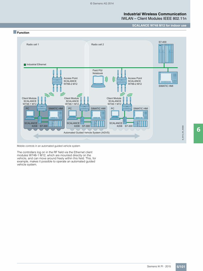
6/101Siemens IK PI · 2015
Industrial Wireless CommunicationIWLAN – Client Modules IEEE 802.11n
SCALANCE W748 M12 for indoor use
6
■ Function
Mobile controls in an automated guided vehicle system
The controllers log on in the RF field via the Ethernet client modules W748-1 M12, which are mounted directly on the vehicle, and can move around freely within this field. This, for example, makes it possible to operate an automated guided vehicle system.
Radio cell 1 Radio cell 2
Automated Guided Vehicle System (AGVS)
G_I
K10
_XX
_302
82
Industrial Ethernet
S7-400
SIMATIC HMI
Access PointSCALANCEW788-2 M12
Access PointSCALANCEW788-2 M12
Client ModuleSCALANCE
W748-1 M12
Client ModuleSCALANCE
W748-1 M12
Client ModuleSCALANCE
W748-1 M12
Field PG/Notebook
PC PCSIMATIC HMI PCSIMATIC HMI
S7-300SCALANCE
X208 S7-300SCALANCE
X208 S7-300SCALANCE
X208
SIMATIC HMI
Kap_06_IWC_en.book Seite 101 Dienstag, 7. Oktober 2014 1:47 13
© Siemens AG 2014

6/102 Siemens IK PI · 2015
Industrial Wireless CommunicationIWLAN – Client Modules IEEE 802.11n
SCALANCE W748 M12 for indoor use
6
■ Technical specifications
Article No. 6GK5748-1GD00-0AA06GK5748-1GD00-0AB01)
Product-type designation SCALANCE W748-1 M12
Transmission rate
Transmission rate• with W-LAN maximum 450 Mbit/s• with Industrial Ethernet 10 … 1 000 Mbit/s• note -
Interfaces
Number of electrical connections• for network components
and terminal equipment1
• for power supply 1• for redundant power supply 1
Design of electrical connection• for network components
and terminal equipmentM12 interface (8-pole, A-coded), PoE
• for power supply M12 interface (4-pole, A-coded), PoE
Number of optical interfacesfor optical waveguide at 100 Mbit/s
-
Design of optical interfacefor optical waveguide at 100 Mbit/s
-
Design of the removable storage C-PLUG
Yes
Interfaces wireless
Number of radio cards permanently installed
1
Number of internal antennas -
Number of electrical connectionsfor external antenna(s)
3
Design of the electrical connectionfor external antenna(s)
N-Connect (socket)
Product property external antenna can be mounted directly on device
Yes
Supply voltage, current consumption, power loss
Type of supply voltage DC
Supply voltage• 1 from M12 Power Connector (A-
coded) for redundant power supply19.2 V
• 2 from M12 Power Connector (A-coded) for redundant power supply
28.8 V
• from Power-over-Ethernet according IEEE802.3at for type 1 and IEEE802.3af
48 V
• from Power-over-Ethernet according IEEE802.3at for type 2
50 V
Current consumed• at 24 V with DC typical 0.45 A• with Power-over-Ethernet according
to IEEE802.3at for type 1 and IEEE802.3af typical
0.22 A
• with Power-over-Ethernet according to IEEE802.3at for type 2 typical
0.21 A
Active power loss• at 24V for DC typical 10.7 W• with Power-over-Ethernet according
to IEEE802.3at for type 1 and IEEE802.3af typical
10.7 W
• with Power-over-Ethernet according to IEEE802.3at for type 2 typical
10.7 W
1) Wireless approval in the USA
Permitted ambient conditions
Ambient temperature• during operating -20 … +60 °C• during storage -40 … +70 °C• during transport -40 … +70 °C
Relative humidity at 25 °C without condensation during operating maximum
100 %
Protection class IP IP65
Ambient condition for (standard) operation mode
When used under hazardous conditions (Zone 2), the product must be installed in an enclosure. To comply with EN 50021, this enclosure must meet the require-ments of at least IP54 in compliance with EN 60529.
Design, dimensions and weight
Width of enclosure without antenna 200 mm
Height of enclosure without antenna 176 mm
Depth of enclosure without antenna 79 mm
Net weight 1.7 kg
Mounting type wall mounting Yes
Mounting type S7-300 rail mounting
Wireless frequencies
Radio frequency• for WLAN in 2.4 GHz frequency
band2.41 … 2.48 GHz
• for WLAN in 5 GHz frequency band 4.9 … 5.8 GHz
Product properties, functions, components general
Product function• Access Point Mode No• Client Mode Yes
Number of SSIDs 1
Product function• iPCF Access Point -• iPCF client Yes• iPCF-MC Access Point -• iPCF-MC client in preparation
Number of iPCF-capable radio modules
1
Article No. 6GK5748-1GD00-0AA06GK5748-1GD00-0AB01)
Product-type designation SCALANCE W748-1 M12
Kap_06_IWC_en.book Seite 102 Dienstag, 7. Oktober 2014 1:47 13
© Siemens AG 2014

6/103Siemens IK PI · 2015
6
■ Technical specifications (continued)
Industrial Wireless CommunicationIWLAN – Client Modules IEEE 802.11n
SCALANCE W748 M12 for indoor use
Product functions management, configuration
Number of manageable IP addresses in client
8
Product function• CLI Yes• web-based management Yes• MIB support Yes• TRAPs via email Yes• Configuration with STEP 7 in preparation• configuration with STEP 7
in the TIA Portalin preparation
• operation with IWLAN controller -• operation with Enterasys WLAN
controller-
• forced roaming with IWLAN No• WDS No
Protocol is supported• Address Resolution Protocol (ARP) Yes• ICMP Yes• Telnet Yes• HTTP Yes• HTTPS Yes• TFTP Yes• SNMP v1 Yes• SNMP v2 Yes• SNMP v3 Yes• DCP Yes• LLDP Yes
Identification & maintenance function• I&M0 - device-specific information Yes• I&M1 – higher level designation/
location designationYes
Product functions Diagnosis
Product function• PROFINET IO diagnosis in preparation• localization via Aeroscout -• SysLog Yes
Product functions VLAN
Product function function VLAN with IWLAN
No
Product functions DHCP
Product function• DHCP client Yes• in Client Mode DHCP server
via LANNo
Product functions Redundancy
Protocol is supported STP/RSTP -
Product functions Security
Product function• ACL - MAC-based -• Management security, ACL-IP based Yes• IEEE 802.1x (radius) Yes• NAT/NAPT No• access protection according to
IEEE802.11iYes
• WPA/WPA2 Yes• TKIP/AES Yes
Protocol is supported SSH Yes
1) Wireless approval in the USA
Article No. 6GK5748-1GD00-0AA06GK5748-1GD00-0AB01)
Product-type designation SCALANCE W748-1 M12
Product functions Time
Protocol is supported• SNTP Yes• SIMATIC Time Yes
Standards, specifications, approvals
Standard• for hazardous zone EN 60079-15:2005, EN 60079-
0:2006, II 3 G Ex nA II T4 KEMA 07 ATEX 0145X
• for safety of CSA and UL UL 60950-1 CSA C22.2 No. 60950-1
Verification of suitability• CE mark Yes• EC declaration of conformity Yes• C-Tick Yes• CCC No• Railway application in accordance
with EN 50155No
• e1 approval No• E1 approval No• NEMA4X No• Power-over-Ethernet according
IEEE802.3at for type 1 and IEEE802.3af
Yes
• Power-over-Ethernet according to IEEE802.3at for type 2
Yes
Standard for wireless communication• IEEE 802.11a Yes• IEEE 802.11b Yes• IEEE 802.11e Yes• IEEE 802.11g Yes• IEEE 802.11h Yes• IEEE 802.11i Yes• IEEE 802.11n Yes
Wireless approval You will find the current list of countries at: www.siemens.com/wireless-approvals
Accessories
Accessories -
Article No. 6GK5748-1GD00-0AA06GK5748-1GD00-0AB01)
Product-type designation SCALANCE W748-1 M12
Kap_06_IWC_en.book Seite 103 Dienstag, 7. Oktober 2014 1:47 13
© Siemens AG 2014

6/104 Siemens IK PI · 2015
Industrial Wireless CommunicationIWLAN – Client Modules IEEE 802.11n
SCALANCE W748 M12 for indoor use
6
■ Ordering data Article No. Article No.
1) Please note national approvals under http://www.siemens.com/wireless-approvals
■ More information
Selection tools:
To assist in selecting Industrial Ethernet components, the TIA Selection Tool is available at:http://www.siemens.com/tia-selection-tool
Wireless approvals:
Current approvals can be found on the Internet at: http://www.siemens.com/wireless-approvals
SCALANCE W748 client modules
IWLAN Ethernet client modules with built-in wireless interface; wireless networksIEEE 802.11a/b/g/h/n at 2.4/5 GHz up to 450 Mbps; WPA2/AES; Power over Ethernet (PoE),IP65 degree of protection(-20 °C to +60 °C); scope of supply: Mounting hardware; manual on CD-ROM, German/English
SCALANCE W748-1 M12
For managing the wireless connection of up to eight linked devices with Industrial Ethernet connection• National approvals
for operation outside the USA6GK5748-1GD00-0AA0
• National approvals • for operation within the USA 1)
6GK5748-1GD00-0AB0
Accessories
KEY-PLUG W740 iFeatures 6GK5907-4PA00
Swap medium for enabling additional iFeatures, for simple device replacement if a fault occurs and for storage of configuration data; Can be used in SCALANCE W client modules with PLUG compartment
C-PLUG 6GK1900-0AB00
Swap medium for simple replace-ment of devices in the event of a fault; for storing configuration data; can be used in SIMATIC NET products with PLUG compartment
DIN rail mounting adapter 6GK5798-8ML00-0AB3
DIN rail mounting adapter for SCALANCE W788 M12 and SCALANCE W788 RJ45; screw fixing for mounting on a 35 mm DIN rail to EN 50 022; scope of supply: 3 units per pack
IE FC M12 Plug PRO 4 x 2
M12 plug-in connector suitable for on-site assembly (X-coded, IP65/IP67), metal enclosure, insulation displacement fast connec-tion method, for SCALANCE W• 1 unit 6GK1901-0DB30-6AA0• 8 units 6GK1901-0DB30-6AA8
IE FC Standard Cable GP 4 x 2 6XV1878-2A
8-core, shielded TP installation cable for connection to IE FC RJ45 Plug 4 x 2 and IE M12 Plug PRO 4 x 2; PROFINET-compliant; with UL approval; sold by the meter; max. length 1 000 m, minimum order quantity 20 m
IE FC Stripping Tool 6GK1901-1GA00
Preadjusted stripping toolfor fast stripping of the Industrial Ethernet FC cables
Power M12 Cable Connector PRO 6GK1 907-0DC10-6AA3
Terminal socket for connectionof SCALANCE W700 for 24 V DC supply voltage; 4-pole, A-coded, with assembly instructions, 3 units
Power Cable 2 x 0.75 6XV1 812-8A
Connecting cable for Power M12 Cable Connector PRO, sold by the meter
Antennas and miscellaneous IWLAN accessories
See Industrial Wireless LAN/accessories
Kap_06_IWC_en.book Seite 104 Dienstag, 7. Oktober 2014 1:47 13
© Siemens AG 2014

6/105Siemens IK PI · 2015
Industrial Wireless CommunicationIWLAN – Client Modules IEEE 802.11n
SCALANCE W734 RJ45 for use in control cabinet
6
■ Overview
• Client modules in SIMATIC design suitable for applications where the device is to be mounted in the control cabinet
SIMATIC ET 200MP station with SCALANCE W734 RJ45
■ Design
• Low-profile, compact aluminum enclosure, shock and vibration-proof for high mechanical requirements
• Implementation of simple and cost-effective wireless machine networking
• Support of the 2.4 and 5 GHz frequency band• IP30 degree of protection• For use at ambient temperatures from -20 °C to +60 °C• 2 x R-SMA sockets for the connection of direct mountable and
remote antennas • Antenna placement optimized for the 2x2 MIMO technology;
the antennas do not interfere with each other when they are mounted directly on the device
• 2 x RJ45 connector for 10/100 Mbit/s, of which one connector has Power-over-Ethernet compliant with IEEE 802.3at
• 2 x 24 V DC connection for redundant energy supply• 1 x PLUG compartment for KEY-PLUG/C-PLUG• Function LEDs for optical signaling of faults/errors and
operating statuses• Mounting: Wall, S7-1500 mounting rail, S7-300 mounting rail,
or on 35 mm standard mounting rail• SIMATIC design matches existing components in the control
cabinet (e.g. ET 200MP, etc.)
Design and interfaces of the SCALANCE W734 RJ45 client modules
Product versions
SCALANCE W734-1 RJ45• A radio card is permanently installed; functional scope can be
expanded by using a KEY-PLUG W740 iFeatures
2x antenna connections R-SMA (female)
24 V DC connection
2x RJ45 connection 10/100 Mbit/s with integrated 2 port switch; 1 port supports PoE IEEE 802.3at
PLUG slot and reset button
Kap_06_IWC_en.book Seite 105 Dienstag, 7. Oktober 2014 1:47 13
© Siemens AG 2014

6/106 Siemens IK PI · 2015
Industrial Wireless CommunicationIWLAN – Client Modules IEEE 802.11n
SCALANCE W734 RJ45 for use in control cabinet
6
■ Function
Use of the SCALANCE W734-1 RJ45 in a suspended monorail
Radio cell
AntennaANT792-4DN
Han
ger 1
Han
ger 2
Han
ger 3
Han
ger 4
Han
ger 5
G_I
K10
_XX
_301
71
RCoax Cable
Client Module SCALANCE W734-1 RJ45+ KEY-PLUG W740 iFeatures
Access Point SCALANCE W774-1 RJ45+ KEY-PLUG W780 iFeatures
Kap_06_IWC_en.book Seite 106 Dienstag, 7. Oktober 2014 1:47 13
© Siemens AG 2014

6/107Siemens IK PI · 2015
Industrial Wireless CommunicationIWLAN – Client Modules IEEE 802.11n
SCALANCE W734 RJ45 for use in control cabinet
6
■ Technical specifications
Article No. 6GK5734-1FX00-0AA06GK5734-1FX00-0AB01)
Product-type designation SCALANCE W734-1 RJ45
Transmission rate
Transmission rate• with W-LAN maximum 300 Mbit/s• with Industrial Ethernet 10 … 100 Mbit/s• note -
Interfaces
Number of electrical connections• for network components
and terminal equipment2
• for power supply 1• for redundant power supply 1
Design of the electrical connection• for network components
and terminal equipmentRJ45 socket
• for power supply 4-pole screw terminal, PoE
Number of optical interfaces for optical waveguide at 100 Mbit/s
-
Design of optical interfacefor optical waveguide at 100 Mbit/s
-
Design of the removable storage C-PLUG
Yes
Interfaces wireless
Number of radio cards permanently installed
1
Number of internal antennas -
Number of electrical connections for external antenna(s)
2
Design of the electrical connection for external antenna(s)
R-SMA (socket)
Product property external antenna can be mounted directly on device
Yes
Supply voltage, current consump-tion, power loss
Type of supply voltage DC
Supply voltage• 1 from terminal block 19.2 V• 2 from terminal block 28.8 V• from Power-over-Ethernet according
IEEE802.3at for type 1 and IEEE802.3af
48 V
• from Power-over-Ethernet according IEEE802.3at for type 2
-
Current consumed• at 24 V with DC typical 0.25 A• with Power-over-Ethernet according
to IEEE802.3at for type 1 and IEEE802.3af typical
0.125 A
• with Power-over-Ethernet according to IEEE802.3at for type 2 typical
-
Effective power loss• at 24V for DC typical 6 W• with Power-over-Ethernet according
to IEEE802.3at for type 1 and IEEE802.3af typical
6 W
• with Power-over-Ethernet according to IEEE802.3at for type 2 typical
-
1) Wireless approval in the USA
Permitted ambient conditions
Ambient temperature• during operating -20 … +60 °C• during storage -40 … +85 °C• during transport -40 … +85 °C
Relative humidity at 25 °C without condensation during operating maxi-mum
97 %
Protection class IP IP30
Ambient condition for (standard) operation mode
When used under hazardous conditions (Zone 2), the SCALANCE W774-1 RJ45 or W734-1 RJ45 prod-uct must be installed in an enclosure. To comply with EN 50021, this enclosure must meet the require-ments of at least IP5 in compliance with EN 60529.
Design, dimensions and weight
Width of enclosure without antenna 26 mm
Height of enclosure without antenna 147 mm
Depth of enclosure without antenna 127 mm
Net weight 0.52 kg
Mounting type wall mounting Yes
Mounting type Wall mounting only if flat mounted
Wireless frequencies
Radio frequency• for WLAN in 2.4 GHz
frequency band2.41 … 2.48 GHz
• for WLAN in 5 GHzfrequency band
4.9 … 5.8 GHz
Product properties, functions, com-ponents general
Product function• Access Point Mode No• Client Mode Yes
Number of SSIDs -
Product function• iPCF Access Point -• iPCF client Yes• iPCF-MC Access Point -• iPCF-MC client Yes
Number of iPCF-capable radio modules
1
Article No. 6GK5734-1FX00-0AA06GK5734-1FX00-0AB01)
Product-type designation SCALANCE W734-1 RJ45
Kap_06_IWC_en.book Seite 107 Dienstag, 7. Oktober 2014 1:47 13
© Siemens AG 2014

6/108 Siemens IK PI · 2015
6
■ Technical specifications (continued)
Industrial Wireless CommunicationIWLAN – Client Modules IEEE 802.11n
SCALANCE W734 RJ45 for use in control cabinet
Product functions management, configuration
Number of manageable IP addresses in client
8
Product function• CLI Yes• web-based management Yes• MIB support Yes• TRAPs via email Yes• Configuration with STEP 7 in preparation• configuration with STEP 7
in the TIA Portalin preparation
• operation with IWLAN controller -• operation with Enterasys WLAN
controller-
• forced roaming with IWLAN No• WDS No
Protocol is supported• Address Resolution Protocol (ARP) Yes• ICMP Yes• Telnet Yes• HTTP Yes• HTTPS Yes• TFTP Yes• SNMP v1 Yes• SNMP v2 Yes• SNMP v3 Yes• DCP Yes• LLDP Yes
Identification & maintenance function• I&M0 - device-specific information Yes• I&M1 – higher level designation/lo-
cation designationYes
Product functions Diagnosis
Product function• PROFINET IO diagnosis in preparation• localization via Aeroscout No• SysLog Yes
Product functions VLAN
Product function function VLAN with IWLAN
No
Product functions DHCP
Product function• DHCP client Yes• in Client Mode DHCP server
via LANNo
1) Wireless approval in the USA
Article No. 6GK5734-1FX00-0AA06GK5734-1FX00-0AB01)
Product-type designation SCALANCE W734-1 RJ45
Product functions Security
Product function• ACL - MAC-based No• Management security,
ACL-IP basedYes
• IEEE 802.1x (radius) Yes• NAT/NAPT No• access protection according to
IEEE802.11iYes
• WPA/WPA2 Yes• TKIP/AES Yes
Protocol is supported SSH Yes
Product functions Time
Protocol is supported• SNTP Yes• SIMATIC Time Yes
Standards, specifications, approvals
Standard• for hazardous zone in preparation• for safety of CSA and UL -
Verification of suitability• CE mark Yes• EC declaration of conformity Yes• C-Tick Yes• CCC -• Railway application in accordance
with EN 50155-
• e1 approval• E1 approval -• NEMA4X -• Power-over-Ethernet according
IEEE802.3at for type 1 and IEEE802.3af
Yes
• Power-over-Ethernet according to IEEE802.3at for type 2
Yes
Standard for wireless communication• IEEE 802.11a Yes• IEEE 802.11b Yes• IEEE 802.11e Yes• IEEE 802.11g Yes• IEEE 802.11h Yes• IEEE 802.11i Yes• IEEE 802.11n Yes
Wireless approval You will find the current list of countries at: www.siemens.com/wireless-approvals
Accessories
Accessories 24 V DC screw terminal included in scope of delivery
Article No. 6GK5734-1FX00-0AA06GK5734-1FX00-0AB01)
Product-type designation SCALANCE W734-1 RJ45
Kap_06_IWC_en.book Seite 108 Dienstag, 7. Oktober 2014 1:47 13
© Siemens AG 2014
6/109Siemens IK PI · 2015
Industrial Wireless CommunicationIWLAN – Client Modules IEEE 802.11n
SCALANCE W734 RJ45 for use in control cabinet
6
■ Ordering data Article No.
1) Please note national approvals underhttp://www.siemens.com/wireless approvals
■ More information
Selection tools:
To assist in selecting Industrial Ethernet components, the TIA Selection Tool is available at:http://www.siemens.com/tia-selection-tool
Wireless approvals:
Current approvals can be found on the Internet at: http://www.siemens.com/wireless-approvals
SCALANCE W734 Client Modules
IWLAN Ethernet client modules with built-in wireless interface; wireless networks IEEE 802.11a/b/g/h/n at 2.4/5 GHz up to 300 Mbit/s; WPA2/AES; integrated 2-port switch; Power over Ethernet (PoE),IP30 degree of protection (-20 °C to +60 °C); scope of delivery: Mounting hardware, 4-pin screw terminal for 24V DC; manual on CD-ROM; German/English
SCALANCE W734-1 RJ45
for managing the wireless connec-tion of up to eight linked devices with Industrial Ethernet connection• National approvals
for operation outside the USA6GK5734-1FX00-0AA0
• National approvals for operation within the USA 1)
6GK5734-1FX00-0AB0
Accessories
KEY-PLUG W740 iFeatures 6GK5907-4PA00
Swap medium for enabling addi-tional iFeatures, for simple device replacement if a fault occurs and for storage of configuration data; can be used in SCALANCE W client modules with PLUG compartment
C-PLUG 6GK1900-0AB00
Swap medium for simple replace-ment of devices if a fault occurs; for storing configuration data; can be used in SIMATIC NET products with PLUG compartment
IE FC RJ45 Plug 180 2 x 2
RJ45 plug connector for Industrial Ethernet with a rugged metal enclosure and integrated insulation-displacement contacts for connecting Industrial Ethernet FC installation cables; with a 180° cable outlet; for network components and CPs/CPUs with Industrial Ethernet interface• 1 pack = 1 unit 6GK1901-1BB10-2AA0• 1 pack = 10 units 6GK1901-1BB10-2AB0• 1 pack = 50 units 6GK1901-1BB10-2AE0
IE FC Standard Cable GP 2 x 2 6XV1840-2AH10
4-core, shielded TP installation cable for connection to IE FC outlet RJ45 plug / IE FC RJ45 plug; PROFINET-compliant; with UL approvalSold by the metermax. quantity 1 000 mminimum order 20 m
IE FC Stripping Tool 6GK1901-1GA00
Preadjusted stripping toolfor fast stripping of the Industrial Ethernet FC cables
Antennas and miscellaneous IWLAN accessories
See Industrial Wireless LAN/accessories
Kap_06_IWC_en.book Seite 109 Dienstag, 7. Oktober 2014 1:47 13
© Siemens AG 2014

6/110 Siemens IK PI · 2015
Industrial Wireless CommunicationIWLAN – Client Modules IEEE 802.11n
SCALANCE W722 RJ45 for use in control cabinet
6
■ Overview
• Low-cost Client Module, suitable for applications where the device is to be mounted in the control cabinet
• Equipped with iFeatures
SIMATIC ET 200SP station with SCALANCE W722 RJ45
■ Design
• Compact design for space-saving installation in control cabinets or boxes on a standard mounting rail
• Implementation of simple and cost-effective wireless machine networking
• Support of the 2.4 and 5 GHz frequency band• Degree of protection IP20 • For use at ambient temperatures from 0 °C to +55 °C • 1 x R-SMA socket for the connection of a remote antenna • 1 x RJ45 port for 10/100 Mbit/s • 1 x 24 V DC connection • Function LEDs for optical signaling of faults/errors and
operating statuses• SIMATIC design matches existing components in the control
cabinet (e.g. ET 200SP, etc.)
Design and interfaces of the SCALANCE W722 RJ45 client modules
Product versions
SCALANCE W722-1 RJ45 • A wireless card permanently installed in the device;
suitable for establishing wireless connections with iFeatures
1 x antenna connection R-SMA (female)
24 V DC connection (rear)
RJ45 connection for 10/100 Mbit/s (front)
Reset button
Kap_06_IWC_en.book Seite 110 Dienstag, 7. Oktober 2014 1:47 13
© Siemens AG 2014

6/111Siemens IK PI · 2015
Industrial Wireless CommunicationIWLAN – Client Modules IEEE 802.11n
SCALANCE W722 RJ45 for use in control cabinet
6
■ Function
Integration of an automated guided vehicle system using iPCF with the SCALANCE W722-1 RJ45
■ Technical specifications
RCoax Cable Segment 1 RCoax Cable Segment 2
Access PointSCALANCE
W784-1RR inthe cabinet
Access PointSCALANCEW784-1RR inthe cabinet
G_I
K10
_XX
_301
72IWLAN RCoax Cable IWLAN RCoax Cable
Client ModuleSCALANCE W722-1 RJ45
Panel PC
Client ModuleSCALANCE W722-1 RJ45
Panel PC
Client ModuleSCALANCE W722-1 RJ45
Panel PC
WinAC WinACWinAC
Article No. 6GK5722-1FC00-0AA06GK5722-1FC00-0AB01)
Product-type designation SCALANCE W722-1 RJ45
Transmission rate
Transmission rate• with W-LAN maximum 150 Mbit/s• with Industrial Ethernet 10 … 100 Mbit/s• note -
Interfaces
Number of electrical connections• for network components
and terminal equipment1
• for power supply 1• for redundant power supply 0
Design of the electrical connection• for network components
and terminal equipmentRJ45 socket
• for power supply 3-pole screw terminal
Number of optical interfaces for optical waveguide at 100 Mbit/s
-
Design of optical interfacefor optical waveguide at 100 Mbit/s
-
Design of the removable storage C-PLUG
No
Interfaces wireless
Number of radio cards permanently installed
1
Number of internal antennas -
Number of electrical connectionsfor external antenna(s)
1
Design of the electrical connectionfor external antenna(s)
R-SMA (socket)
Product property external antenna can be mounted directly on device
Yes
1) Wireless approval in the USA
Supply voltage, current consumption, power loss
Type of supply voltage DC
Supply voltage• 1 from terminal block 19.2 V• 2 from terminal block 28.8 V• from Power-over-Ethernet
according IEEE802.3at for type 1 and IEEE802.3af
-
• from Power-over-Ethernet according IEEE802.3at for type 2
-
Current consumed• at 24 V with DC typical 0.15 A• with Power-over-Ethernet
according to IEEE802.3at for type 1 and IEEE802.3af typical
-
• with Power-over-Ethernet according to IEEE802.3at for type 2 typical
-
Effective power loss• at 24V for DC typical 3.6 W• with Power-over-Ethernet
according to IEEE802.3at for type 1 and IEEE802.3af typical
-
• with Power-over-Ethernetaccording to IEEE802.3at for type 2 typical
-
Article No. 6GK5722-1FC00-0AA06GK5722-1FC00-0AB01)
Product-type designation SCALANCE W722-1 RJ45
Kap_06_IWC_en.book Seite 111 Dienstag, 7. Oktober 2014 1:47 13
© Siemens AG 2014

6/112 Siemens IK PI · 2015
6
■ Technical specifications (continued)
Industrial Wireless CommunicationIWLAN – Client Modules IEEE 802.11n
SCALANCE W722 RJ45 for use in control cabinet
Permitted ambient conditions
Ambient temperature• during operating 0 … 55 °C• during storage -40 … +85 °C• during transport -40 … +85 °C
Relative humidity at 25 °C without condensation during operating maxi-mum
95 %
Protection class IP IP20
Ambient condition for (standard) operation mode
When used under hazardous conditions (Zone 2), the SCALANCE W761-1 RJ45 or W72x-1 RJ45 prod-uct must be installed in an enclosure. To comply with EN 50021, this enclosure must meet the require-ments of at least IP54 in compliance with EN 60529.
Design, dimensions and weight
Width of enclosure without antenna 50 mm
Height of enclosure without antenna 114 mm
Depth of enclosure without antenna 74 mm
Net weight 0.13 kg
Mounting type wall mounting No
Wireless frequencies
Radio frequency• for WLAN in 2.4 GHz frequency
band2.41 … 2.48 GHz
• for WLAN in 5 GHz frequency band 4.9 … 5.8 GHz
Product properties, functions, com-ponents general
Product function• Access Point Mode No• Client Mode Yes
Number of SSIDs -
Product function• iPCF Access Point -• iPCF client Yes• iPCF-MC Access Point -• iPCF-MC client Yes
Number of iPCF-capable radio mod-ules
1
Article No. 6GK5722-1FC00-0AA06GK5722-1FC00-0AB01)
Product-type designation SCALANCE W722-1 RJ45
Product functions management, configuration
Number of manageable IP addresses in client
4
Product function• CLI Yes• web-based management Yes• MIB support Yes• TRAPs via email Yes• Configuration with STEP 7 in preparation• configuration with STEP 7
in the TIA Portalin preparation
• operation with IWLAN controller -• operation with Enterasys WLAN
controller-
• forced roaming with IWLAN No• WDS No
Protocol is supported• Address Resolution Protocol (ARP) Yes• ICMP Yes• Telnet Yes• HTTP Yes• HTTPS Yes• TFTP Yes• SNMP v1 Yes• SNMP v2 Yes• SNMP v3 Yes• DCP Yes• LLDP No
Identification & maintenance function• I&M0 - device-specific information Yes• I&M1 – higher level designation/
location designationYes
Product functions Diagnosis
Product function• PROFINET IO diagnosis No• Link Check No• connection monitoring IP-Alive No• localization via Aeroscout No• SysLog Yes
Product functions VLAN
Product function function VLAN with IWLAN
No
Product functions DHCP
Product function• DHCP client Yes• in Client Mode DHCP server via LAN No
Article No. 6GK5722-1FC00-0AA06GK5722-1FC00-0AB01)
Product-type designation SCALANCE W722-1 RJ45
Kap_06_IWC_en.book Seite 112 Dienstag, 7. Oktober 2014 1:47 13
© Siemens AG 2014

6/113Siemens IK PI · 2015
■ Technical specifications (continued)
Industrial Wireless CommunicationIWLAN – Client Modules IEEE 802.11n
SCALANCE W722 RJ45 for use in control cabinet
6
1) Wireless approval in the USA
Product functions Security
Product function• ACL - MAC-based No• Management security,
ACL-IP basedYes
• IEEE 802.1x (radius) Yes• NAT/NAPT No• access protection according to
IEEE802.11iYes
• WPA/WPA2 Yes• TKIP/AES Yes
Protocol is supported SSH Yes
Product functions Time
Protocol is supported• SNTP Yes• SIMATIC Time Yes
Standards, specifications, approvals
Standard• for hazardous zone in preparation• for safety of CSA and UL -
Verification of suitability• CE mark Yes• EC declaration of conformity Yes• C-Tick Yes• CCC -• Railway application in accordance
with EN 50155-
• e1 approval• E1 approval -• NEMA4X -• Power-over-Ethernet according
IEEE802.3at for type 1 and IEEE802.3af
No
• Power-over-Ethernet according to IEEE802.3at for type 2
No
Standard for wireless communication• IEEE 802.11a Yes• IEEE 802.11b Yes• IEEE 802.11e Yes• IEEE 802.11g Yes• IEEE 802.11h Yes• IEEE 802.11i Yes• IEEE 802.11n Yes
Wireless approval You will find the current list of countries at: www.siemens.com/wireless-approvals
Accessories
Accessories 24 V DC screw terminal included in scope of delivery
Article No. 6GK5722-1FC00-0AA06GK5722-1FC00-0AB01)
Product-type designation SCALANCE W722-1 RJ45
■ Ordering data
1) Please note national approvals under http://www.siemens.com/wireless-approvals
■ More information
Selection tools:
To assist in selecting Industrial Ethernet components, the TIA Selection Tool is available at:http://www.siemens.com/tia-selection-tool
Wireless approvals:
Current approvals can be found on the Internet at: http://www.siemens.com/wireless-approvals
SCALANCE W722 Client Modules
IWLAN Ethernet Client Modules with iFeatures support and built-in wireless interface; wireless networks IEEE 802.11a/b/g/h/n at 2.4/5 GHz up to 150 Mbit/s; WPA2/AES; IP20 degree of protection (0 °C to +55 °C); scope of delivery: Mounting hardware, 3-pin screw terminal for 24V DC; manual on CD-ROM; German/English
SCALANCE W722-1 RJ45
for administration of the wireless connection with iFeatures from a connected device with Industrial Ethernet connection• National approvals
for operation outside the USA6GK5722-1FC00-0AA0
• National approvals for operation within the USA 1)
6GK5722-1FC00-0AB0
Accessories
IE FC RJ45 Plug 180 2 x 2
RJ45 plug connector for Industrial Ethernet with a rugged metal enclosure and integrated insulation-displacement contacts for connecting Industrial Ethernet FC installation cables; with a 180° cable outlet; for network components and CPs/CPUs with Industrial Ethernet interface• 1 pack = 1 unit 6GK1901-1BB10-2AA0• 1 pack = 10 units 6GK1901-1BB10-2AB0• 1 pack = 50 units 6GK1901-1BB10-2AE0
IE FC Standard Cable GP 2 x 2 6XV1840-2AH10
4-core, shielded TP installation cable for connection to IE FC outlet RJ45 plug / IE FC RJ45 plug; PROFINET-compliant; with UL approvalSold by the metermax. quantity 1 000 m minimum order 20 m
IE FC Stripping Tool 6GK1901-1GA00
Preadjusted stripping tool for fast stripping of the Industrial Ethernet FC cables
Antennas and miscellaneous IWLAN accessories
See Industrial Wireless LAN/accessories
Kap_06_IWC_en.book Seite 113 Dienstag, 7. Oktober 2014 1:47 13
© Siemens AG 2014
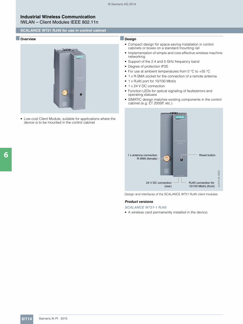
6/114 Siemens IK PI · 2015
Industrial Wireless CommunicationIWLAN – Client Modules IEEE 802.11n
SCALANCE W721 RJ45 for use in control cabinet
6
■ Overview
• Low-cost Client Module, suitable for applications where the device is to be mounted in the control cabinet
■ Design
• Compact design for space-saving installation in control cabinets or boxes on a standard mounting rail
• Implementation of simple and cost-effective wireless machine networking
• Support of the 2.4 and 5 GHz frequency band• Degree of protection IP20 • For use at ambient temperatures from 0 °C to +55 °C • 1 x R-SMA socket for the connection of a remote antenna • 1 x RJ45 port for 10/100 Mbit/s • 1 x 24 V DC connection • Function LEDs for optical signaling of faults/errors and
operating statuses• SIMATIC design matches existing components in the control
cabinet (e.g. ET 200SP, etc.)
Design and interfaces of the SCALANCE W721 RJ45 client modules
Product versions
SCALANCE W721-1 RJ45• A wireless card permanently installed in the device;
1 x antenna connection R-SMA (female)
24 V DC connection (rear)
RJ45 connection for 10/100 Mbit/s (front)
Reset button
Kap_06_IWC_en.book Seite 114 Dienstag, 7. Oktober 2014 1:47 13
© Siemens AG 2014

6/115Siemens IK PI · 2015
Industrial Wireless CommunicationIWLAN – Client Modules IEEE 802.11n
SCALANCE W721 RJ45 for use in control cabinet
6
■ Integration
Storage and retrieval systems in high-bay warehouses automated with SCALANCE W721-1 RJ45, W761-1 RJ45 and RCoax
■ Technical specifications
Antenna cable
Antenna ANT793-4MN
Antenna cable
Antenna cable
Antenna cable
Control cabinetCentral control unit
SIMATIC ET 200S with SCALANCE W761-1 RJ45
and SCALANCE XB005
IWLAN RCoax radiating cable
IWLAN RCoax radiating cable
IWLAN RCoax radiating cable
IWLAN RCoax radiating cable
Storage retrieval machine SCALANCE W721-1 RJ45and ET 200SP
Storage retrieval machine SCALANCE W721-1 RJ45and ET 200SP
Storage retrieval machine SCALANCE W721-1 RJ45and ET 200SP
Storage retrieval machine SCALANCE W721-1 RJ45and ET 200SP
Antenna ANT793-4MN
Antenna ANT793-4MN
Antenna ANT793-4MN
G_I
K10
_XX
_303
34
Industrial Ethernet/PROFINET
SCALANCE W761-1 RJ45
SCALANCE W761-1 RJ45
SCALANCE W761-1 RJ45
Article No. 6GK5721-1FC00-0AA06GK5721-1FC00-0AB01)
Product-type designation SCALANCE W721-1 RJ45
Transmission rate
Transmission rate• with W-LAN maximum 150 Mbit/s• with Industrial Ethernet 10 … 100 Mbit/s• note -
Interfaces
Number of electrical connections• for network components
and terminal equipment1
• for power supply 1• for redundant power supply 0
Design of the electrical connection• for network components
and terminal equipmentRJ45 socket
• for power supply 3-pole screw terminal
Number of optical interfacesfor optical waveguide at 100 Mbit/s
-
Design of optical interfacefor optical waveguide at 100 Mbit/s
-
Design of the removable storage C-PLUG
No
1) Wireless approval in the USA
Interfaces wireless
Number of radio cards permanently installed
1
Number of internal antennas -
Number of electrical connections for external antenna(s)
1
Design of the electrical connection for external antenna(s)
R-SMA (socket)
Product property external antenna can be mounted directly on device
Yes
Article No. 6GK5721-1FC00-0AA06GK5721-1FC00-0AB01)
Product-type designation SCALANCE W721-1 RJ45
Kap_06_IWC_en.book Seite 115 Dienstag, 7. Oktober 2014 1:47 13
© Siemens AG 2014

6/116 Siemens IK PI · 2015
6
■ Technical specifications (continued)
Industrial Wireless CommunicationIWLAN – Client Modules IEEE 802.11n
SCALANCE W721 RJ45 for use in control cabinet
Supply voltage, current consumption, power loss
Type of supply voltage DC
Supply voltage• 1 from terminal block 19.2 V• 2 from terminal block 28.8 V• from Power-over-Ethernet
according IEEE802.3at for type 1 and IEEE802.3af
-
• from Power-over-Ethernet according IEEE802.3at for type 2
-
Current consumed• at 24 V with DC typical 0.15 A• with Power-over-Ethernet
according to IEEE802.3at for type 1 and IEEE802.3af typical
-
• with Power-over-Ethernet according to IEEE802.3at for type 2 typical
-
Effective power loss• at 24V for DC typical 3.6 W• with Power-over-Ethernet
according to IEEE802.3at for type 1 and IEEE802.3af typical
-
• with Power-over-Ethernet according to IEEE802.3at for type 2 typical
-
Permitted ambient conditions
Ambient temperature• during operating 0 … 55 °C• during storage -40 … +85 °C• during transport -40 … +85 °C
Relative humidity at 25 °C without condensation during operating maximum
95 %
Protection class IP IP20
Ambient condition for (standard) operation mode
When used under hazardous conditions (Zone 2), the SCALANCE W761-1 RJ45 or W72x-1 RJ45 prod-uct must be installed in an enclosure. To comply with EN 50021, this enclosure must meet the require-ments of at least IP54 in compliance with EN 60529.
Design, dimensions and weight
Width of enclosure without antenna 50 mm
Height of enclosure without antenna 114 mm
Depth of enclosure without antenna 74 mm
Net weight 0.13 kg
Mounting type wall mounting No
Wireless frequencies
Radio frequency• for WLAN in 2.4 GHz frequency
band2.41 … 2.48 GHz
• for WLAN in 5 GHz frequency band 4.9 … 5.8 GHz
Article No. 6GK5721-1FC00-0AA06GK5721-1FC00-0AB01)
Product-type designation SCALANCE W721-1 RJ45
Product properties, functions, components general
Product function• Access Point Mode No• Client Mode Yes
Number of SSIDs -
Product function• iPCF Access Point -• iPCF client -• iPCF-MC Access Point -• iPCF-MC client -
Number of iPCF-capable radio modules
-
Product functions management, configuration
Number of manageable IP addresses in client
4
Product function• CLI Yes• web-based management Yes• MIB support Yes• TRAPs via email Yes• Configuration with STEP 7 in preparation• configuration with STEP 7
in the TIA Portalin preparation
• operation with IWLAN controller -• operation with Enterasys WLAN
controller-
• forced roaming with IWLAN No• WDS No
Protocol is supported• Address Resolution Protocol (ARP) Yes• ICMP Yes• Telnet Yes• HTTP Yes• HTTPS Yes• TFTP Yes• SNMP v1 Yes• SNMP v2 Yes• SNMP v3 Yes• DCP Yes• LLDP No
Identification & maintenance function• I&M0 - device-specific information Yes• I&M1 – higher level designation/
location designationYes
Product functions Diagnosis
Product function• PROFINET IO diagnosis No• localization via Aeroscout No• SysLog Yes
Product functions VLAN
Product function function VLAN with IWLAN
No
Product functions DHCP
Product function• DHCP client Yes• in Client Mode DHCP server
via LANNo
Article No. 6GK5721-1FC00-0AA06GK5721-1FC00-0AB01)
Product-type designation SCALANCE W721-1 RJ45
Kap_06_IWC_en.book Seite 116 Dienstag, 7. Oktober 2014 1:47 13
© Siemens AG 2014

6/117Siemens IK PI · 2015
■ Technical specifications (continued)
Industrial Wireless CommunicationIWLAN – Client Modules IEEE 802.11n
SCALANCE W721 RJ45 for use in control cabinet
6
1) Wireless approval in the USA
Product functions Security
Product function• ACL - MAC-based No• Management security,
ACL-IP basedYes
• IEEE 802.1x (radius) Yes• NAT/NAPT No• access protection
according to IEEE802.11iYes
• WPA/WPA2 Yes• TKIP/AES Yes
Protocol is supported SSH Yes
Product functions Time
Protocol is supported• SNTP Yes• SIMATIC Time Yes
Standards, specifications, approvals
Standard• for hazardous zone in preparation• for safety of CSA and UL -
Verification of suitability• CE mark Yes• EC declaration of conformity Yes• C-Tick Yes• CCC -• Railway application
in accordance with EN 50155-
• e1 approval• E1 approval -• NEMA4X -• Power-over-Ethernet
according IEEE802.3at for type 1 and IEEE802.3af
No
• Power-over-Ethernet according to IEEE802.3at for type 2
No
Standard for wireless communication• IEEE 802.11a Yes• IEEE 802.11b Yes• IEEE 802.11e Yes• IEEE 802.11g Yes• IEEE 802.11h Yes• IEEE 802.11i Yes• IEEE 802.11n Yes
Wireless approval You will find the current list of countries at: www.siemens.com/wireless-approvals
Accessories
Accessories 24 V DC screw terminal included in scope of delivery
Article No. 6GK5721-1FC00-0AA06GK5721-1FC00-0AB01)
Product-type designation SCALANCE W721-1 RJ45
■ Ordering data Article No.
1) Please note national approvals under http://www.siemens.com/wireless-approvals
■ More information
Selection tools:
To assist in selecting Industrial Ethernet components, the TIA Selection Tool is available at:http://www.siemens.com/tia-selection-tool
Wireless approvals:
Current approvals can be found on the Internet at: http://www.siemens.com/wireless-approvals
SCALANCE W721 Client Modules
IWLAN Ethernet Client Modules with built-in wireless interface; wireless networks IEEE 802.11a/b/g/h/n at 2.4/5 GHz up to 150 Mbit/s; WPA2/AES; IP20 degree of protection (0 °C to +55 °C); scope of delivery: Mounting hardware, 3-pin screw terminal for 24V DC; manual on CD-ROM; German/English
SCALANCE W721-1 RJ45
For administration of the wireless connection from a connected device with Industrial Ethernet connection• National approvals for operation
outside the USA6GK5721-1FC00-0AA0
• National approvals for operation within the USA 1)
6GK5721-1FC00-0AB0
Accessories
IE FC RJ45 Plug 180 2 x 2
RJ45 plug connector for Industrial Ethernet with a rugged metal enclosure and integrated insulation-displacement contacts for connect-ing Industrial Ethernet FC installation cables; with a 180° cable outlet; for network components and CPs/CPUs with Industrial Ethernet interface• 1 pack = 1 unit 6GK1901-1BB10-2AA0• 1 pack = 10 units 6GK1901-1BB10-2AB0• 1 pack = 50 units 6GK1901-1BB10-2AE0
IE FC Standard Cable GP 2 x 2 6XV1840-2AH10
4-core, shielded TP installation cable for connection to IE FC outlet RJ45 plug / IE FC RJ45 plug; PROFINET-compliant; with UL approval; sold by the meter; max. quantity 1 000 m, minimum order 20 m
IE FC Stripping Tool 6GK1901-1GA00
Preadjusted stripping tool for fast stripping of the Industrial Ethernet FC cables
Antennas and miscellaneous IWLAN accessories
See Industrial Wireless LAN/accessories
Kap_06_IWC_en.book Seite 117 Dienstag, 7. Oktober 2014 1:47 13
© Siemens AG 2014

6/118 Siemens IK PI · 2015
Industrial Wireless CommunicationIWLAN – Accessories
IWLAN antennas
6
■ Overview
Remote antennas increase the reliability of wireless links by optimizing the receiving and emission of signals.• Use in Industrial Wireless LAN (IWLAN) and WLAN in
accordance with IEEE 802.11 at 2.4 GHz and 5 GHz with transmission rates of up to 450 Mbit/s
• Coordinated range of antennas for the most diverse applica-tions both indoors and outdoors
• Antennas with two (dual-slant) or three (MIMO) connections for increased data throughput and increased reliability of the wireless connection thanks to selective use of multiple path propagation
• Suitable for use in hazardous areas (Zone 2); no special approvals necessary
■ Benefits
• Investment protection thanks to compliance with the globally recognized standard IEEE 802.11 and – depending on the version – suitability for 2.4 GHz and/or 5 GHz
• Cost-effective connection to devices in remote, difficult-to-access, or hostile environments
• Establishment of a reliable IWLAN wireless infrastructure through the use of remote antennas, even if the access points and client modules are installed in the cabinet, for example
■ Application
Separate antennas optimize the transmission and receiving conditions and support the use of IWLAN products in a number of industrial applications. With sector antennas, for example, conveyor lines or corridors can be specifically covered with radio links, or strongly directional antennas can be used to implement point-to-point connections over distances of up to several 1 000 meters.
Alternatively, an omnidirectional antenna concentrates the radio field around the antenna in the shape of a disc, which enhances the quality of the connection.
Antennas with two or three connections enable transmission of the two to three streams usual with IEEE 802.11n, using just one antenna. They are available both with omnidirectional and directional characteristics.
Application examples:
Omnidirectional antennas• Coverage of an area which has at its center a pole for
mounting the antenna• Installation of the antenna on the roof in the case of automated
guided vehicle systems for reliable data exchange with the vehicles
• Wide-area coverage of a production cell or robot station
Sector antennas• Selective coverage of warehouse/high-bay warehouse aisles
with the help of a wide-angle antenna prevents interference with neighboring wireless fields
Directional antennas• Communication between buildings over long distances with
the help of an antenna with narrow opening angle and high gain
Kap_06_IWC_en.book Seite 118 Dienstag, 7. Oktober 2014 1:47 13
© Siemens AG 2014

6/119Siemens IK PI · 2015
Industrial Wireless CommunicationIWLAN – Accessories
IWLAN antennas
6
■ Design
Omnidirectional and sector antennas IWLAN directional antennas and RCoax radiating cable
Ant
enne
nart
Freq
uenz
(G
Hz)
Ant
enne
n
SC
ALA
NC
EW
780/
W74
0
SC
ALA
NC
EW
770/
W73
0
SC
ALA
NC
EW
760/
W72
0
omni
dire
ktio
nal
2,4 ANT792-6MN ● ● ●
2,4 und
5
ANT795-4MA ● ● ●
ANT795-4MC ●
ANT795-4MD ●
ANT795-6MN ● ● ●
ANT795-6MT ●
5 ANT793-6MN ● ● ●
Sek
tor
2,4 und
5ANT795-6DC ● ●
5
ANT793-6DG ● ●
ANT793-6DT ●
Type
of a
nten
na
Freq
uenc
yra
nge
(GH
z)
Ant
enna
s
SC
ALA
NC
EW
780/
W74
0
SC
ALA
NC
EW
770/
W73
0
SC
ALA
NC
EW
760/
W72
0
omni
dire
ctio
nal
2.4 ANT792-6MN ● ● ●
2.4 and
5
ANT795-4MA ● ● ●
ANT795-4MC ●
ANT795-4MD ●
ANT795-6MN ● ● ●
ANT795-6MT ●
5 ANT793-6MN ● ● ●
Sec
tor
2.4 and
5ANT795-6DC ● ●
5
ANT793-6DG ● ●
ANT793-6DT ●
Type
of a
nten
na
Freq
uenc
yra
nge
(GH
z)
Ant
enna
s
SC
ALA
NC
EW
780/
W74
0
SC
ALA
NC
EW
770/
W73
0
SC
ALA
NC
EW
760/
W72
0
dire
ctio
nal
2.4 ANT792-8DN ●
5
ANT793-8DP ●
ANT793-8DJ ●
ANT793-8DK ●
RC
oax
2.4
RCoax radiating cables 2.4 GHz
● ● ●
G_I
K10
_XX
_303
17
ANT792-4DN ● ● ●
5
RCoax radiating cables 5 GHz
● ● ●
ANT793-4MN ● ● ●
Kap_06_IWC_en.book Seite 119 Dienstag, 7. Oktober 2014 1:47 13
© Siemens AG 2014

6/120 Siemens IK PI · 2015
Industrial Wireless CommunicationIWLAN – Accessories
IWLAN antennas
6
■ Function
Separate antennas are used to optimize the radio field for the application. In industrial applications, this permits a reliable radio link.
Antennas with multiple connections (dual or MIMO antennas)
Antennas with two connections combine two individual antennas, at 90° to each other, in a single antenna enclosure. With these antennas, two data streams can be transferred simultaneously thanks to the two different polarization levels. Depending on the alignment of the polarization levels, these antennas are referred to as dual-slant (rotated through +/-45°) or vertical-horizontal.
Antennas with three connections contain three individual emit-ters that can be combined in a single enclosure, either on differ-ent polarization levels (0°, +/-45°) or at a suitable distance from each other. The MIMO antennas can transmit or receive three data streams simultaneously using multiple path propagation.
Transmission of several data streams results in increased data throughput and simultaneously a more reliable data transfer.
Directional effect
The suitable antenna is selected first by means of the wireless field characteristic. A distinction is made between omnidirec-tional antennas and directional antennas.
Omnidirectional antennas
Omnidirectional antenna
With omnidirectional antennas, the radio field is emitted in every direction surrounding the antenna (horizontal opening angle: 360°), but it weakens as the distance increases. There is a concentration in the vertical direction which creates passive amplification of the radio field. Many omnidirectional antennas have extremely weak radiation directly below the antenna due to their type of construction. This property can be seen in the associated antenna diagram.
ANT795-4Mx
With these omnidirectional antennas, the radio field is concen-trated at 2.4 GHz and 5 GHz in the vertical plane of the antenna. All antennas of this type have an opening angle of 30° in the vertical direction and an antenna gain of 3/5 dBi. They are directly mounted on the R-SMA or N connector of the SCALANCE W enclosure.
ANT795-4MA, ANT795-4MC and ANT795-4MD
The ANT795-4MC and ANT 795-4MD antennas can be rotated around only one axis, they have N-Connect connectors and degree of protection IP65 and are used with the SCALANCE W788 M12 Access Points and the SCALANCE W748 M12 Client Modules.
The ANT795-4MA antenna features an additional joint, an R-SMA connector, and degree of protection IP30. It is therefore optimally suitable for the SCALANCE W788 RJ45, W770 and W760 Access Points and the SCALANCE W748 RJ45, W730 and W720 Client Modules.
ANT792-6MN, ANT793-6MN
With these omnidirectional antennas, the radio field is concen-trated at 2.4 GHz (ANT792-6MN) and 5 GHz (ANT793-6MN) in the vertical plane of the antenna. The antennas have a gain of 6 dBi and 5 dBi respectively.
N-Connect is used as the connection plug and can be con-nected to SCALANCE W over an antenna connection cable from the range of IWLAN cabling. Both antennas are supplied with a mounting aid (metal bracket) that supports wall or mast mount-ing. The antennas are therefore ideally suited, for example, to providing radio coverage for a place that has a mast at its center on which they can be mounted.
ANT795-6MN, antenna mounting tool for ANT795-6MN
With this omnidirectional antenna, the radio field is concentrated at 2.4 GHz and 5 GHz in the vertical plane of the antenna. The antenna has a gain of 6 dBi and 8 dBi respectively.
N-Connect is used as connection plug. The antenna can be connected to SCALANCE W over an antenna connection cable from the IWLAN cabling systems range. The antenna character-istic is such that good transmission properties also exist directly above and below the antenna. It is designed for mounting on a control cabinet or roof, but it can also be mounted under a roof, so it is suitable, for example, for the mobile units of an automated guided vehicle system. If it needs to be installed on a ceiling under a roof, the optional antenna mounting tool for ANT795-6MN is used.
ANT795-6MT
This antenna is an omnidirectional MIMO antenna with three QMA connections. The wireless field is concentrated at 2.4 GHz and 5 GHz in the vertical plane of the antenna. The antenna has a gain of 6 dBi.
The antenna characteristic is such that good transmission properties also exist directly above and below the antenna. It is designed for mounting on a roof or (together with the supplied mounting bracket) under a ceiling, and it is thus suitable, for example, for the mobile units of automated guided vehicle systems.
The ANT795-6MT is connected to the SCALANCE W-780/W740 Access Points via QMA/N-Connect male/female IWLAN adapter cables and the IWLAN flexible antenna connection cables in the relevant length and connector version.
Horizontalopeningangle
Verticalopening
angle
G_I
K10
_XX
_300
27
Kap_06_IWC_en.book Seite 120 Dienstag, 7. Oktober 2014 1:47 13
© Siemens AG 2014
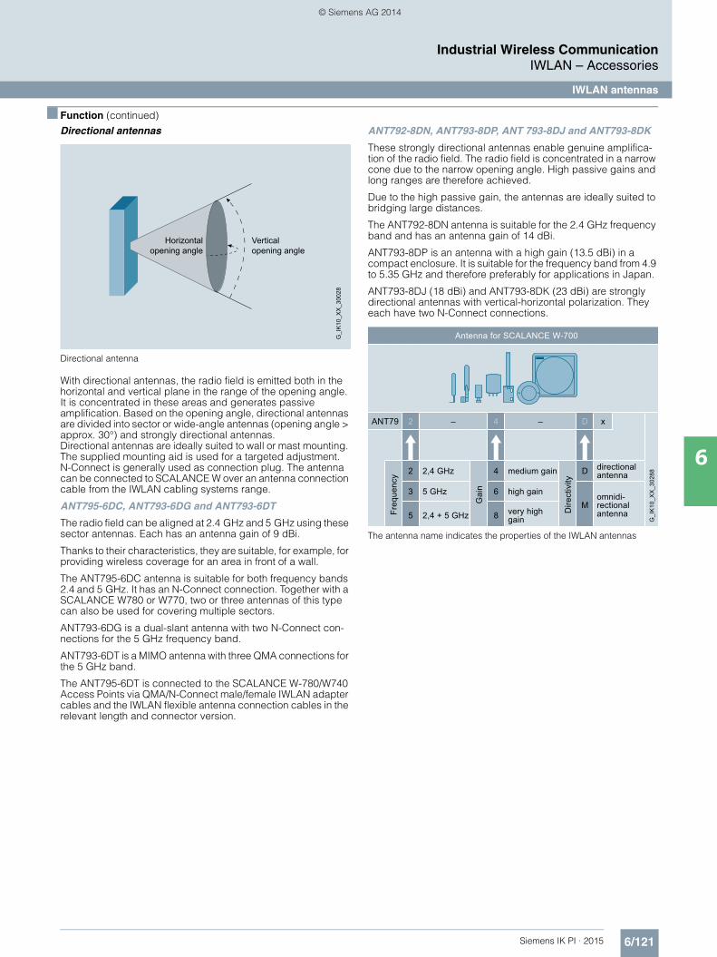
6/121Siemens IK PI · 2015
6
■ Function (continued)
Industrial Wireless CommunicationIWLAN – Accessories
IWLAN antennas
Directional antennas
Directional antenna
With directional antennas, the radio field is emitted both in the horizontal and vertical plane in the range of the opening angle. It is concentrated in these areas and generates passive amplification. Based on the opening angle, directional antennas are divided into sector or wide-angle antennas (opening angle > approx. 30°) and strongly directional antennas.Directional antennas are ideally suited to wall or mast mounting. The supplied mounting aid is used for a targeted adjustment.N-Connect is generally used as connection plug. The antenna can be connected to SCALANCE W over an antenna connection cable from the IWLAN cabling systems range.
ANT795-6DC, ANT793-6DG and ANT793-6DT
The radio field can be aligned at 2.4 GHz and 5 GHz using these sector antennas. Each has an antenna gain of 9 dBi.
Thanks to their characteristics, they are suitable, for example, for providing wireless coverage for an area in front of a wall.
The ANT795-6DC antenna is suitable for both frequency bands 2.4 and 5 GHz. It has an N-Connect connection. Together with a SCALANCE W780 or W770, two or three antennas of this type can also be used for covering multiple sectors.
ANT793-6DG is a dual-slant antenna with two N-Connect con-nections for the 5 GHz frequency band.
ANT793-6DT is a MIMO antenna with three QMA connections for the 5 GHz band.
The ANT795-6DT is connected to the SCALANCE W-780/W740 Access Points via QMA/N-Connect male/female IWLAN adapter cables and the IWLAN flexible antenna connection cables in the relevant length and connector version.
ANT792-8DN, ANT793-8DP, ANT 793-8DJ and ANT793-8DK
These strongly directional antennas enable genuine amplifica-tion of the radio field. The radio field is concentrated in a narrow cone due to the narrow opening angle. High passive gains and long ranges are therefore achieved.
Due to the high passive gain, the antennas are ideally suited to bridging large distances.
The ANT792-8DN antenna is suitable for the 2.4 GHz frequency band and has an antenna gain of 14 dBi.
ANT793-8DP is an antenna with a high gain (13.5 dBi) in a compact enclosure. It is suitable for the frequency band from 4.9 to 5.35 GHz and therefore preferably for applications in Japan.
ANT793-8DJ (18 dBi) and ANT793-8DK (23 dBi) are strongly directional antennas with vertical-horizontal polarization. They each have two N-Connect connections.
The antenna name indicates the properties of the IWLAN antennas
Verticalopening angle
Horizontalopening angle
G_I
K10
_XX
_300
28Antenna for SCALANCE W-700
ANT79 2 – 4 – D x
G_I
K10
_XX
_302
88
Freq
uenc
y 2 2,4 GHzG
ain
4 medium gain
Dire
ctiv
ity
D directional antenna
3 5 GHz 6 high gainM
omnidi-rectional antenna5 2,4 + 5 GHz 8 very high
gain
Kap_06_IWC_en.book Seite 121 Dienstag, 7. Oktober 2014 1:47 13
© Siemens AG 2014
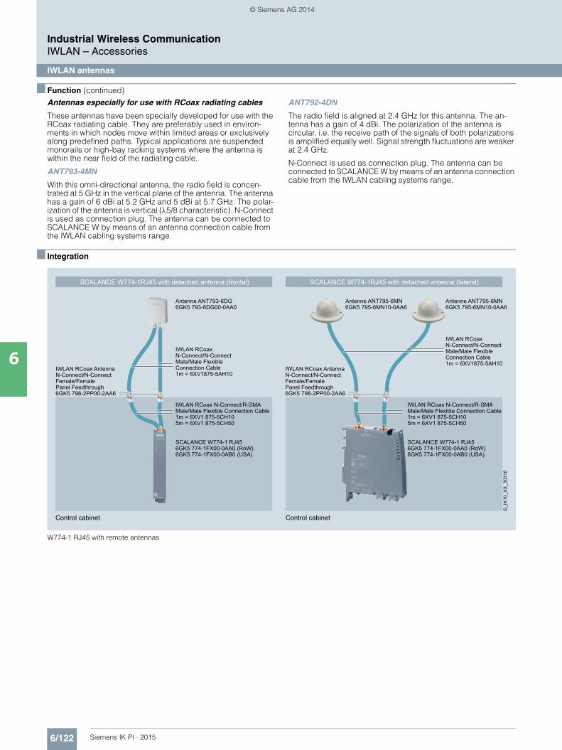
6/122 Siemens IK PI · 2015
■ Function (continued)
Industrial Wireless CommunicationIWLAN – Accessories
IWLAN antennas
6
Antennas especially for use with RCoax radiating cables
These antennas have been specially developed for use with the RCoax radiating cable. They are preferably used in environ-ments in which nodes move within limited areas or exclusively along predefined paths. Typical applications are suspended monorails or high-bay racking systems where the antenna is within the near field of the radiating cable.
ANT793-4MN
With this omni-directional antenna, the radio field is concen-trated at 5 GHz in the vertical plane of the antenna. The antenna has a gain of 6 dBi at 5.2 GHz and 5 dBi at 5.7 GHz. The polar-ization of the antenna is vertical (5/8 characteristic). N-Connect is used as connection plug. The antenna can be connected to SCALANCE W by means of an antenna connection cable from the IWLAN cabling systems range.
ANT792-4DN
The radio field is aligned at 2.4 GHz for this antenna. The an-tenna has a gain of 4 dBi. The polarization of the antenna is circular, i.e. the receive path of the signals of both polarizations is amplified equally well. Signal strength fluctuations are weaker at 2.4 GHz.
N-Connect is used as connection plug. The antenna can be connected to SCALANCE W by means of an antenna connection cable from the IWLAN cabling systems range.
■ Integration
W774-1 RJ45 with remote antennas
Control cabinetControl cabinet
SCALANCE W774-1RJ45 with detached antenna (lateral)SCALANCE W774-1RJ45 with detached antenna (frontal)
G_I
K10
_XX
_303
16
Antenne ANT795-6MN 6GK5 795-6MN10-0AA6
Antenne ANT795-6MN 6GK5 795-6MN10-0AA6
IWLAN RCoax N-Connect/R-SMA Male/Male Flexible Connection Cable1m = 6XV1 875-5CH105m = 6XV1 875-5CH50
IWLAN RCoax N-Connect/N-Connect Male/Male Flexible Connection Cable1m = 6XV1875-5AH10
Antenne ANT793-6DG6GK5 793-6DG00-0AA0
SCALANCE W774-1 RJ456GK5 774-1FX00-0AA0 (RoW)6GK5 774-1FX00-0AB0 (USA)
SCALANCE W774-1 RJ456GK5 774-1FX00-0AA0 (RoW)6GK5 774-1FX00-0AB0 (USA)
IWLAN RCoax AntennaN-Connect/N-ConnectFemale/FemalePanel Feedthrough6GK5 798-2PP00-2AA6
IWLAN RCoax Antenna N-Connect/N-Connect Female/FemalePanel Feedthrough 6GK5 798-2PP00-2AA6
IWLAN RCoax N-Connect/R-SMA Male/Male Flexible Connection Cable1m = 6XV1 875-5CH105m = 6XV1 875-5CH50
IWLAN RCoax N-Connect/N-Connect Male/Male Flexible Connection Cable1m = 6XV1875-5AH10
Kap_06_IWC_en.book Seite 122 Dienstag, 7. Oktober 2014 1:47 13
© Siemens AG 2014

6/123Siemens IK PI · 2015
6
■ Integration (continued)
Industrial Wireless CommunicationIWLAN – Accessories
IWLAN antennas
SCALANCE W761-1 RJ45 and SCALANCE W788-2 M12 with remote antennas
Control cabinet
Antenna ANT793-6MN connected to SCALANCE W761-1 RJ45 (frontal)
G_I
K10
_XX
_303
14
Antenne ANT793-6MN 6GK5 793-6MN00-0AA6
IWLAN RCoax Antenna N-Connect/N-Connect Female/FemalePanel Feedthrough 6GK5 798-2PP00-2AA6
IWLAN RCoax N-Connect/R-SMA Male/Male Flexible Connection Cable1m = 6XV1 875-5CH105m = 6XV1 875-5CH50
IWLAN RCoax N-Connect/N-Connect Male/Male Flexible Connection Cable1m = 6XV1875-5AH10
SCALANCE W761-1 RJ456GK5761-1FC00-0AA0 (RoW) 6GK5761-1FC00-0AB0 (USA)
Lightning protector6GK5 798-2LP10-2AA6(Scope of delivery: 1 items)
MIMO antenna ANT795-6MT connected to SCALANCE W788-2 M12 with N-Connect ports
IWLAN N-Connect/N-Connect Male/Male Flexible Connection Cable2 m = 6XV1 875-5AH20(Scope of delivery: 1 items)
QMA/N-Connect Male/Female Flexible Connection Cable 6XV1 875-5JH10(Scope of delivery: 3 items)
G_I
K10
_XX
_303
15
IWLAN Antenna ANT795-6MT6GK5 795-6MT00-0AA0
SCALANCE W788-2 M126GK5 788-2GD00-0AA0
Kap_06_IWC_en.book Seite 123 Dienstag, 7. Oktober 2014 1:47 13
© Siemens AG 2014

6/124 Siemens IK PI · 2015
6
■ Integration (continued)
Industrial Wireless CommunicationIWLAN – Accessories
IWLAN antennas
SCALANCE W788-1 RJ45 access points with dual slant antenna and SCALANCE W788-1 M12 with N-Connect connection
All antennas can be used with an N-Connect female connector.
Lightning protector6GK5 798-2LP10-2AA6
Lightning protector6GK5 798-2LP10-2AA6
Resistance6GK5 795-1TN00-1AA0
Resistance6GK5 795-1TR10-0AA6
Dual Slant antenna ANT793-6DG connected to SCALANCE W788-2 RJ45 with R-SMA ports
Dual Slant antenna ANT793-6DG connected to SCALANCE W788-2 M12 with N-Connect ports
G_IK1
0_XX
_302
72
IWLAN Antenna ANT793-6DG6GK5 793-6DG00-0AA0
IWLAN Antenna ANT793-6DG6GK5 793-6DG00-0AA0
IWLAN N-Connect/N-Connect Male/MaleFlexible Connection Cable1 m = 6XV1 875-5AH10
IWLAN N-Connect/N-ConnectFemale/FemalePanel Feedthrough6GK5 798-2PP00-2AA6
IWLAN N-Connect / N-ConnectMale/MaleFlexible Connection Cable5 m = 6XV1 875-5AH50
IWLAN N-Connect/N-Connect Male/MaleFlexible Connection Cable1 m = 6XV1 875-5AH10
IWLAN N-Connect/N-ConnectFemale/FemalePanel Feedthrough6GK5 798-2PP00-2AA6
IWLAN N-Connect/R-SMA Male/MaleFlexible Connection Cable0,3 m = 6XV1 875-5CE30
IWLAN N-Connect / R-SMAMale/MaleFlexible Connection Cable5 m = 6XV1 875-5CH50
SCALANCE W788-2 RJ456GK5 788-2FC00-0AA0
SCALANCE W788-2 M126GK5 788-2GD00-0AA0
Kap_06_IWC_en.book Seite 124 Dienstag, 7. Oktober 2014 1:47 13
© Siemens AG 2014

6/125Siemens IK PI · 2015
Industrial Wireless CommunicationIWLAN – Accessories
IWLAN antennas
6
■ Technical specifications
Article No. 6GK5795-4MC00-0AA3 6GK5795-4MD00-0AA3 6GK5795-4MA00-0AA3
Product-type designation Antenna ANT795-4MC Antenna ANT795-4MD Antenna ANT795-4MA
Wireless frequencies
Radio frequency• for WLAN
in 2.4 GHz frequency band2.4 … 2.4835 GHz 2.4 … 2.4835 GHz 2.4 … 2.4835 GHz
• for WLANin 5 GHz frequency band 1
5.15 … 5.35 GHz 5.15 … 5.35 GHz 5.15 … 5.35 GHz
• for WLANin 5 GHz frequency band 2
5.725 … 5.85 GHz 5.725 … 5.85 GHz 5.725 … 5.85 GHz
Electrical data
Impedance 50 50 50
Polarization linear vertical linear vertical linear vertical
Radiation characteristic omnidirectional omnidirectional omnidirectional
Antenna gain compared to spherical radiator with linear radiation
- - -
Antenna gain compared to spherical radiator with circular radiation
- - -
Antenna gain compared to spherical radiator of the WLAN antenna in the 2.4 GHz frequency band
3 dB 3 dB 3 dB
Antenna gain compared to spherical radiator of the WLAN antenna in the 5 GHz frequency band
5 dB 5 dB 5 dB
Standing wave ratio VSWR maximum 2 2 2
Beam angle of antenna• in the 2.4 GHz frequency band
- horizontal 360° 360° 360°- vertical - - -
• in the 5 GHz frequency band- horizontal 360° 360° 360°- vertical - - -
Opening angle Note - - -
Number of electrical connections of antenna
1 1 1
Design of electrical connection of antenna
N connector N connector R-SMA connector
Angle of inclination downward maximum
0° 0° 0°
Crosstalk attenuation between the antenna connections
- - -
Front-to-back ratio - - -
Transmit power maximum - - -
Transmit power Note - - -
Range with clear line of sight without disturbance
- - -
Range Note - - -
Permitted ambient conditions
Ambient temperature• during operating -20 … +65 °C -20 … +65 °C -20 … +65 °C• during storage -20 … +65 °C -20 … +65 °C -20 … +65 °C• during transport -20 … +65 °C -20 … +65 °C -20 … +65 °C• during installation - - -
Protection class IP IP65 IP65 IP30
Wind load maximum - - -
Wind load Note - - -
Kap_06_IWC_en.book Seite 125 Dienstag, 7. Oktober 2014 1:47 13
© Siemens AG 2014

6/126 Siemens IK PI · 2015
6
■ Technical specifications (continued)
Industrial Wireless CommunicationIWLAN – Accessories
IWLAN antennas
Design, dimensions and weight
Width 35 mm 35 mm 35 mmHeight 160 mm 160 mm 160 mmDepth 13 mm 13 mm 13 mmDiameter - - -
Net weight 26 g 26 g 26 g
Mounting type• mast mounting No No No• wall mounting No No No• roof mounting No No NoMounting type/ directly on the device Yes Yes Yes
Product properties, functions, components general
Product feature silicon-free Yes Yes Yes
Material of outer shell Polycarbonate Polycarbonate Polycarbonate
Standards, specifications, approvals
Standard for hazardous zone - - -
Verification of suitability - - -• RoHS conformity - - -• Railway application
in accordance with EN 50124-1- - -
• Railway applicationin accordance with EN 50155
- - -
• fire protectionin accordance with EN 45545-2
- - -
• UL approval - - -- note - - -
Wireless approval Current national approvals can be found on the Internet underwww.siemens.com/wireless-approvals
Current national approvals can be found on the Internet under www.siemens.com/wireless-approvals
Current national approvals can be found on the Internet under www.siemens.com/wireless-approvals
Article No. 6GK5792-6MN00-0AA6 6GK5793-6MN00-0AA6 6GK5795-6MN10-0AA6 6GK5795-6MT00-0AA0
Product-type designation Antenna ANT792-6MN Antenna ANT793-6MN Antenna ANT795-6MN Antenna ANT795-6MT
Wireless frequencies
Radio frequency• for WLAN
in 2.4 GHz frequency band2.4 … 2.5 GHz - 2.4 … 2.7 GHz 2.4 … 2.69 GHz
• for WLAN in 5 GHz frequency band 1
- 5.15 … 5.875 GHz 3.4 … 3.7 GHz 5.15 … 5.35 GHz
• for WLANin 5 GHz frequency band 2
- - 4.9 … 5.935 GHz 5.47 … 5.935 GHz
Electrical data
Impedance 50 50 50 50
Polarization linear vertical linear vertical linear vertical 3 ports: linear vertical
Radiation characteristic omnidirectional omnidirectional omnidirectional omnidirectional
Antenna gain compared to spherical radiator with linear radiation
- - - -
Antenna gain compared to spherical radiator with circular radiation
- - - -
Antenna gain compared to spherical radiator of the WLAN antenna in the 2.4 GHz frequency band
6 dB - 6 dB 5 dB
Antenna gain compared to spherical radiator of the WLAN antenna in the 5 GHz frequency band
- 5 dB 8 dB 7 dB
Standing wave ratio VSWR maximum 1.8 1.5 1.8 1.5
Article No. 6GK5795-4MC00-0AA3 6GK5795-4MD00-0AA3 6GK5795-4MA00-0AA3
Product-type designation Antenna ANT795-4MC Antenna ANT795-4MD Antenna ANT795-4MA
Kap_06_IWC_en.book Seite 126 Dienstag, 7. Oktober 2014 1:47 13
© Siemens AG 2014

6/127Siemens IK PI · 2015
6
■ Technical specifications (continued)
Industrial Wireless CommunicationIWLAN – Accessories
IWLAN antennas
Beam angle of antenna• in the 2.4 GHz frequency band
- horizontal 360° - 360° 360°- vertical 30° - - -
• in the 5 GHz frequency band- horizontal - 360° 150° 360°- vertical - 25° - -
Opening angle Note - - Note the antenna diagram regarding horizontal beam angle
-
Number of electrical connections of antenna
Design of electrical connection of antenna
Angle of inclination downward maximum
0° 0° 0° 0°
Crosstalk attenuation between the antenna connections
- - - 20 dB
Front-to-back ratio - - - -
Transmit power maximum 25 W 6 W 75 W 10 W
Transmit power Note - at 25° ambient temperature at 25° ambient temperature at 25° ambient temperature
Range with clear line of sight without disturbance
200 m 200 m 200 m -
Range Note Note: The range can be con-siderably less, depending on spatial factors, the wireless standard used, the data rate, and the antennas at the other end
Note: The range can be con-siderably less, depending on spatial factors, the wireless standard used, the data rate, and the antennas at the other end
Note: The range can be con-siderably less, depending on spatial factors, the wireless standard used, the data rate, and the antennas at the other end
-
Permitted ambient conditions
Ambient temperature• during operating -40 … +80 °C -45 … +70 °C -40 … +80 °C -40 … +85 °C• during storage -40 … +80 °C -45 … +70 °C -40 … +80 °C -40 … +85 °C• during transport -40 … +80 °C -45 … +70 °C -40 … +80 °C -40 … +85 °C• during installation - - - -
Protection class IP IP65 IP65 IP65 IP65
Wind load maximum 3 N 3.9 N 10 N -
Wind load Note at 160 km/h at 160 km/h at 160 km/h -
Design, dimensions and weight
Width 50 mm 16 mm 86 mm 282 mmHeight 40 mm 160 mm 43 mm 32 mmDepth 370 mm 16 mm 86 mm 92 mmDiameter - - - -
Net weight 300 g 300 g 300 g 320 g
Mounting type - - - -• mast mounting Yes Yes No No• wall mounting Yes Yes Yes Yes• roof mounting No No Yes YesMounting type/ directly on the device No No No No
Product properties, functions, components general
Product feature silicon-free Yes Yes Yes Yes
Material of outer shell Glass fiber Polypropylene Polycarbonate Polycarbonate
Article No. 6GK5792-6MN00-0AA6 6GK5793-6MN00-0AA6 6GK5795-6MN10-0AA6 6GK5795-6MT00-0AA0
Product-type designation Antenna ANT792-6MN Antenna ANT793-6MN Antenna ANT795-6MN Antenna ANT795-6MT
Kap_06_IWC_en.book Seite 127 Dienstag, 7. Oktober 2014 1:47 13
© Siemens AG 2014

6/128 Siemens IK PI · 2015
6
■ Technical specifications (continued)
Industrial Wireless CommunicationIWLAN – Accessories
IWLAN antennas
Standards, specifications, approvals
Standard for hazardous zone - - - -
Verification of suitability - - Railway application in accordance with NF-F-16-101, NF-F-16-102
-
• RoHS conformity Yes Yes Yes Yes• Railway application
in accordance with EN 50124-1- - Yes -
• Railway applicationin accordance with EN 50155
- - Yes -
• fire protectionin accordance with EN 45545-2
- - - -
• UL approval - - - -- note - - - -
Wireless approval Current national approvals can be found on the Internet under www.siemens.com/wireless-approvals
Current national approvals can be found on the Internet under www.siemens.com/wireless-approvals
Current national approvals can be found on the Internet under www.siemens.com/wireless-approvals
Current national approvals can be found on the Internet under www.siemens.com/wireless-approvals
Article No. 6GK5795-6DC00-0AA0 6GK5793-6DG00-0AA0 6GK5793-6DT00-0AA0
Product-type designation Antenna ANT795-6DC Antenna ANT793-6DG Antenna ANT793-6DT
Wireless frequencies
Radio frequency• for WLAN
in 2.4 GHz frequency band2.4 … 2.5 GHz - -
• for WLAN in 5 GHz frequency band 1
5.15 … 5.875 GHz 5.15 … 5.875 GHz 5.15 … 5.875 GHz
• for WLANin 5 GHz frequency band 2
- - -
Electrical data
Impedance 50 50 50
Polarization linear vertical dual linear +/- 45° slant 3 ports: vertical, +/- 45° slant
Radiation characteristic directional directional directional
Antenna gain compared to spherical radiator with linear radiation
- - -
Antenna gain compared to spherical radiator with circular radiation
- - -
Antenna gain compared to spherical radiator of the WLAN antenna in the 2.4 GHz frequency band
9 dB - -
Antenna gain compared to spherical radiator of the WLAN antennain the 5 GHz frequency band
9 dB 9 dB 8 dB
Standing wave ratio VSWR maximum 2 2 1.7
Beam angle of antenna• in the 2.4 GHz frequency band 75 … 55° - -
Beam angle of antenna in the 5 GHz frequency band horizontal
55° 70° 65°
Beam angle of antenna in the 5 GHz frequency band vertical
55° 60° 65°
Opening angle Note - - -
Number of electrical connectionsof antenna
1 2 3
Design of electrical connection of antenna
N connector N connector QMA connector
Angle of inclination downward max. 0° 0° 0°
Crosstalk attenuation between the antenna connections
25 dB 20 dB 17 dB
Front-to-back ratio 15 dB 20 dB -
Transmit power maximum 10 W 10 W 2 W
Transmit power Note at 25° ambient temperature at 25° ambient temperature at 25° ambient temperature
Range with clear line of sight without disturbance
- - -
Range Note - - -
Article No. 6GK5792-6MN00-0AA6 6GK5793-6MN00-0AA6 6GK5795-6MN10-0AA6 6GK5795-6MT00-0AA0
Product-type designation Antenna ANT792-6MN Antenna ANT793-6MN Antenna ANT795-6MN Antenna ANT795-6MT
Kap_06_IWC_en.book Seite 128 Dienstag, 7. Oktober 2014 1:47 13
© Siemens AG 2014
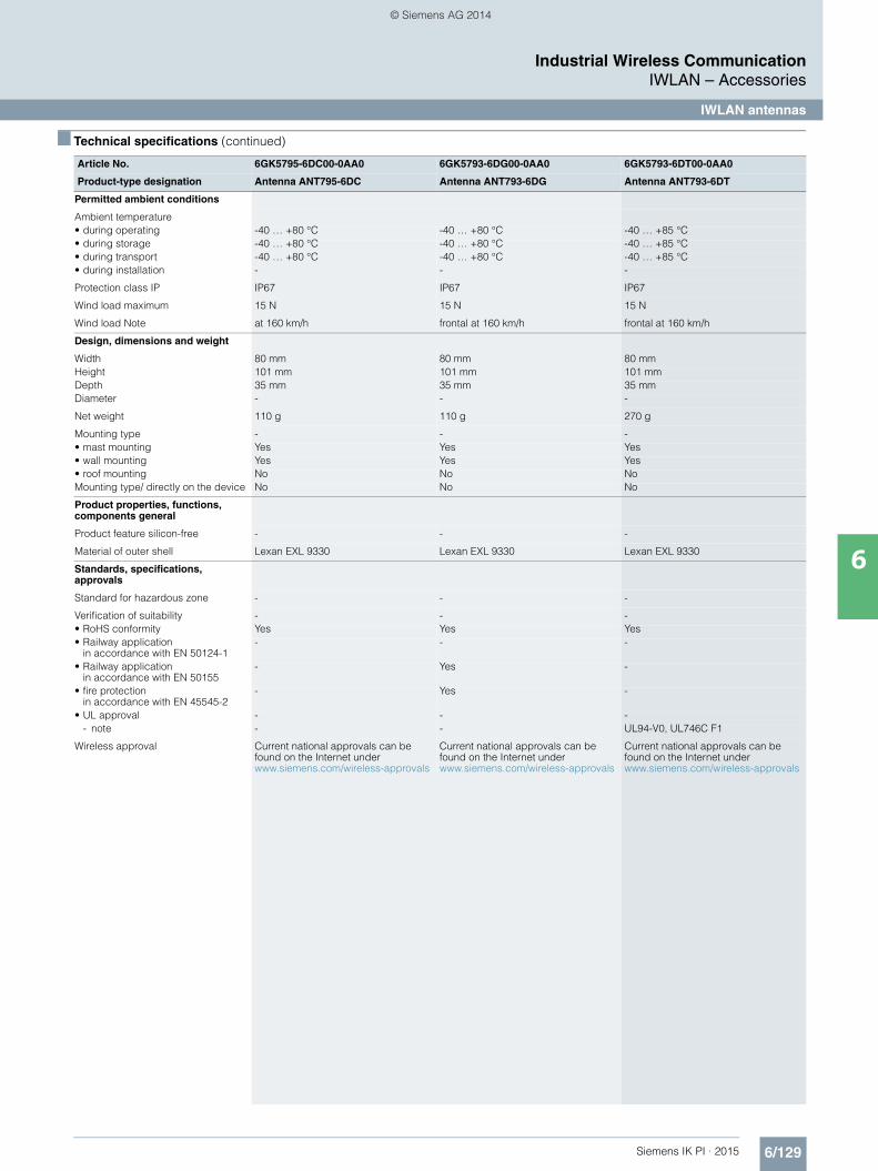
6/129Siemens IK PI · 2015
6
■ Technical specifications (continued)
Industrial Wireless CommunicationIWLAN – Accessories
IWLAN antennas
Permitted ambient conditions
Ambient temperature• during operating -40 … +80 °C -40 … +80 °C -40 … +85 °C• during storage -40 … +80 °C -40 … +80 °C -40 … +85 °C• during transport -40 … +80 °C -40 … +80 °C -40 … +85 °C• during installation - - -
Protection class IP IP67 IP67 IP67
Wind load maximum 15 N 15 N 15 N
Wind load Note at 160 km/h frontal at 160 km/h frontal at 160 km/h
Design, dimensions and weight
Width 80 mm 80 mm 80 mmHeight 101 mm 101 mm 101 mmDepth 35 mm 35 mm 35 mmDiameter - - -
Net weight 110 g 110 g 270 g
Mounting type - - -• mast mounting Yes Yes Yes• wall mounting Yes Yes Yes• roof mounting No No NoMounting type/ directly on the device No No No
Product properties, functions, components general
Product feature silicon-free - - -
Material of outer shell Lexan EXL 9330 Lexan EXL 9330 Lexan EXL 9330
Standards, specifications, approvals
Standard for hazardous zone - - -
Verification of suitability - - -• RoHS conformity Yes Yes Yes• Railway application
in accordance with EN 50124-1- - -
• Railway applicationin accordance with EN 50155
- Yes -
• fire protection in accordance with EN 45545-2
- Yes -
• UL approval - - -- note - - UL94-V0, UL746C F1
Wireless approval Current national approvals can be found on the Internet under www.siemens.com/wireless-approvals
Current national approvals can be found on the Internet under www.siemens.com/wireless-approvals
Current national approvals can be found on the Internet under www.siemens.com/wireless-approvals
Article No. 6GK5795-6DC00-0AA0 6GK5793-6DG00-0AA0 6GK5793-6DT00-0AA0
Product-type designation Antenna ANT795-6DC Antenna ANT793-6DG Antenna ANT793-6DT
Kap_06_IWC_en.book Seite 129 Dienstag, 7. Oktober 2014 1:47 13
© Siemens AG 2014

6/130 Siemens IK PI · 2015
6
■ Technical specifications (continued)
Industrial Wireless CommunicationIWLAN – Accessories
IWLAN antennas
Article No. 6GK5792-8DN00-0AA6 6GK5793-8DJ00-0AA0 6GK5793-8DK00-0AA0 6GK5793-8DP00-0AA0
Product-type designation Antenna ANT792-8DN Antenna ANT793-6DJ Antenna ANT793-6DK Antenna ANT793-8DP
Wireless frequencies
Radio frequency• for WLAN
in 2.4 GHz frequency band2.4 … 2.7 GHz - - -
• for WLANin 5 GHz frequency band 1
- 5.25 … 5.875 GHz 5.15 … 5.875 GHz 4.9 … 5.35 GHz
• for WLANin 5 GHz frequency band 2
- - - -
Electrical data
Impedance 50 50 50 50
Polarization linear vertical dual linear vertical-horizontal dual linear vertical-horizontal linear vertical
Radiation characteristic directional directional directional directional
Antenna gain compared to spherical radiator with linear radiation
- - - -
Antenna gain compared to spherical radiator with circular radiation
- - - -
Antenna gain compared to spherical radiator of the WLAN antenna in the 2.4 GHz frequency band
14 dB - - -
Antenna gain compared to spherical radiator of the WLAN antenna in the 5 GHz frequency band
- 18 dB 23 dB 13.5 dB
Standing wave ratio VSWR maximum 1.5 1.7 1.7 1.5
Beam angle of antenna• in the 2.4 GHz frequency band
- horizontal 35° - - -- vertical 30° - - -
• in the 5 GHz frequency band- horizontal - 17° 9° 40°- vertical - 17° 9° 35°
Opening angle Note - - - -
Number of electrical connections of antenna
1 2 2 1
Design of electrical connection of antenna
N connector N connector N connector N connector
Angle of inclination downward maximum
0° 0° 0° 0°
Crosstalk attenuation between the antenna connections
- 30 dB 40 dB -
Front-to-back ratio 20 dB 30 dB 35 dB 20 dB
Transmit power• maximum 75 W 6 W 6 W 10 W• Note at 25° ambient temperature at 25° ambient temperature at 25° ambient temperature at 25° ambient temperature
Range with clear line of sight without disturbance
1 000 m - - -
Range Note Note: The range can be consider-ably less, depending on spatial factors, the wireless standard used, the data rate, and the antennas at the other end
- - -
Permitted ambient conditions
Ambient temperature• during operating -40 … +80 °C -45 … +70 °C -45 … +70 °C -40 … +80 °C• during storage -40 … +80 °C -45 … +70 °C -45 … +70 °C -40 … +80 °C• during transport -40 … +80 °C -45 … +70 °C -45 … +70 °C -40 … +80 °C• during installation - - - -
Protection class IP IP23 IP67 IP67 IP67
Wind load maximum 57 N 104 N 389 N 15 N
Wind load Note at 160 km/h frontal at 220 km/h frontal at 220 km/h frontal at 160 km/h
Kap_06_IWC_en.book Seite 130 Dienstag, 7. Oktober 2014 1:47 13
© Siemens AG 2014

6/131Siemens IK PI · 2015
6
■ Technical specifications (continued)
Industrial Wireless CommunicationIWLAN – Accessories
IWLAN antennas
Design, dimensions and weight
Width 200 mm 190 mm 371 mm 80 mmHeight 200 mm 190 mm 371 mm 101 mmDepth 43 mm 30.5 mm 40 mm 35 mmDiameter - - - -
Net weight 500 g 700 g 2.5 kg 110 g
Mounting type - - - -• mast mounting Yes Yes Yes Yes• wall mounting Yes Yes Yes Yes• roof mounting No No No NoMounting type/ directly on the device No No No No
Product properties, functions, components general
Product feature silicon-free Yes - - -
Material of outer shell ASA Polycarbonate / aluminum Polycarbonate Lexan EXL 9330
Standards, specifications, approvals
Standard for hazardous zone - - - -
Verification of suitability - - - -• RoHS conformity Yes Yes Yes Yes• Railway application
in accordance with EN 50124-1- - - -
• Railway application• in accordance with EN 50155
- - - -
• fire protection • in accordance with EN 45545-2
- - - -
• UL approval - - - -- note - - - UL94-V0
Wireless approval Current national approvals can be found on the Internet under www.siemens.com/wireless-approvals
Current national approvals can be found on the Internet under www.siemens.com/wireless-approvals
Current national approvals can be found on the Internet under www.siemens.com/wireless-approvals
Current national approvals can be found on the Internet under www.siemens.com/wireless-approvals
Article No. 6GK5792-4DN00-0AA6 6GK5793-4MN00-0AA6
Product-type designation RCoax antenna ANT792-4DN RCoax antenna ANT793-4MN
Wireless frequencies
Radio frequency• for WLAN
in 2.4 GHz frequency band2.4 … 2.4835 GHz -
• for WLANin 5 GHz frequency band 1
- 5.15 … 5.85 GHz
• for WLAN • in 5 GHz frequency band 2
- -
Electrical data
Impedance 50 50
Polarization circular, clockwise vertical (lambda 5/8 characteristic)
Radiation characteristic directional omnidirectional
Antenna gain compared to spherical radiator with linear radiation
- -
Antenna gain compared to spherical radiator with circular radiation
- -
Antenna gain compared to spherical radiator of the WLAN antenna in the 2.4 GHz frequency band
4 dB -
Antenna gain compared to spherical radiator of the WLAN antenna in the 5 GHz frequency band
- 6 dB
Standing wave ratio VSWR maximum 1.8 2
Article No. 6GK5792-8DN00-0AA6 6GK5793-8DJ00-0AA0 6GK5793-8DK00-0AA0 6GK5793-8DP00-0AA0
Product-type designation Antenna ANT792-8DN Antenna ANT793-6DJ Antenna ANT793-6DK Antenna ANT793-8DP
Kap_06_IWC_en.book Seite 131 Dienstag, 7. Oktober 2014 1:47 13
© Siemens AG 2014
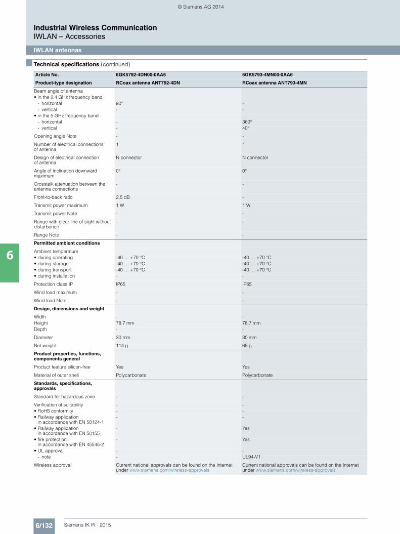
6/132 Siemens IK PI · 2015
6
■ Technical specifications (continued)
Industrial Wireless CommunicationIWLAN – Accessories
IWLAN antennas
Beam angle of antenna• in the 2.4 GHz frequency band
- horizontal 90° -- vertical - -
• in the 5 GHz frequency band- horizontal - 360°- vertical - 40°
Opening angle Note - -
Number of electrical connectionsof antenna
1 1
Design of electrical connection of antenna
N connector N connector
Angle of inclination downward maximum
0° 0°
Crosstalk attenuation between the antenna connections
- -
Front-to-back ratio 2.5 dB -
Transmit power maximum 1 W 1 W
Transmit power Note - -
Range with clear line of sight without disturbance
- -
Range Note - -
Permitted ambient conditions
Ambient temperature• during operating -40 … +70 °C -40 … +70 °C• during storage -40 … +70 °C -40 … +70 °C• during transport -40 … +70 °C -40 … +70 °C• during installation - -
Protection class IP IP65 IP65
Wind load maximum - -
Wind load Note - -
Design, dimensions and weight
Width - -Height 78.7 mm 78.7 mmDepth - -
Diameter 30 mm 30 mm
Net weight 114 g 65 g
Product properties, functions, components general
Product feature silicon-free Yes Yes
Material of outer shell Polycarbonate Polycarbonate
Standards, specifications, approvals
Standard for hazardous zone - -
Verification of suitability - -• RoHS conformity - -• Railway application
in accordance with EN 50124-1- -
• Railway applicationin accordance with EN 50155
- Yes
• fire protectionin accordance with EN 45545-2
- Yes
• UL approval - -- note - UL94-V1
Wireless approval Current national approvals can be found on the Internet under www.siemens.com/wireless-approvals
Current national approvals can be found on the Internet under www.siemens.com/wireless-approvals
Article No. 6GK5792-4DN00-0AA6 6GK5793-4MN00-0AA6
Product-type designation RCoax antenna ANT792-4DN RCoax antenna ANT793-4MN
Kap_06_IWC_en.book Seite 132 Dienstag, 7. Oktober 2014 1:47 13
© Siemens AG 2014

6/133Siemens IK PI · 2015
Industrial Wireless CommunicationIWLAN – Accessories
IWLAN antennas
6
■ Ordering data Article No. Article No.
■ More information
Selection tools:
To assist in the selection of industrial Ethernet components, the TIA Selection Tool is available at: http://www.siemens.com/tia-selection-tool
Cabling range:
You can order components supplementary to the SIMATIC NET cabling range from your local contact. Technical advice on this subject is available from:
J. Hertlein I IA SC CI PRM 4 Phone +49 (911) 750-4465 E-mail: [email protected]
Antennas with omnidirectional characteristics;
National approvals, compact instructions on paper, German/English
For mounting directly onto SCALANCE W
Antenna gain incl. connector 3/5 dBi, 2.4/5 GHz; • ANT795-4MC antenna;
IP65 (-20 to +65 °C),straight connection, N-Connect male, scope of delivery: 1 antenna
6GK5795-4MC00-0AA3
• ANT795-4MD antenna;IP65 (-20 to +65 °C),connection with fixed 90° angle, N-Connect male, scope of delivery: 1 antenna
6GK5795-4MD00-0AA3
• ANT795-4MA antenna; IP30 (-20 to +65 °C);radial rotation possible
• with additional joint; R-SMA male Scope of delivery: 1 antenna
6GK5 795-4MA00-0AA3
Wall or mast mounting• ANT792-6MN antenna
Antenna gain incl. N-Connect connector 6 dBi, 2.4 GHz; IP65 (-40 to +80°C), with terminating resistor 1 x TI795-1R;incl. mounting hardware
6GK5792-6MN00-0AA6
• ANT793-6MN antennaAntenna gain incl. N-Connect connector 5 dBi, 5 GHz; IP65 (-45 to +70 °C), with terminating resistor 1 x TI795-1R;
• incl. mounting hardware
6GK5793-6MN00-0AA6
For mounting on a roof• ANT795-6MN antenna
Antenna gain incl. N-Connectconnector 6/8 dBi, 2.4/5 GHz; IP65 (-40 to +80 °C), with terminating resistor 1 x TI795-1R
6GK5795-6MN10-0AA6
• ANT795-6MT antennaMIMO antenna with 3 QMA sockets, antenna gain 6 dBi, 2.4/5 GHz; (-40 to +85 °C), incl. mounting bracket
6GK5795-6MT00-0AA0
• Antenna mounting tool (ANT795-6MN) Mounting aid for installing ANT795-6MN below a roof
6GK5795-6MN01-0AA6
Directional antennas;
including mounting hardwarefor wall or mast mounting
Sector antennas• ANT795-6DC antenna
Antenna gain incl. N-Connect connector 9/9 dBi, 2.4/5 GHz, -40 to +80 °C
6GK5795-6DC00-0AA0
• ANT793-6DG antennaDual-slant; antenna gain
• incl. two N-Connect connectors 9 dBi, 5 GHz, -40 to +80 °C
6GK5793-6DG00-0AA0
• ANT793-6DT antennaMIMO antenna with 3 QMA sockets; antenna gain 9 dBi, 5 GHz,-40 to +85 °C
6GK5793-6DT00-0AA0
Strongly directional antennas• ANT793-8DN antenna
Antenna gain 13.5 dBi incl. N-Connect connector, 4.9 GHz, -40 to +85 °C, preferably for use in Japan
6GK5793-8DP00-0AA0
• ANT792-8DN antennaAntenna gain incl. N-Connect connector 14 dBi, 2.4 GHz; -40 to +80 °C;with terminating resistor 1 x TI795-1R
6GK5792-8DN00-0AA6
• ANT793-8DJ antennaVertically-horizontally polarized antenna; antenna gain incl. two N-Connect connectors 18 dBi, 5 GHz; -45 to +70 °C
6GK5793-8DJ00-0AA0
• ANT793-8DK antennaVertically-horizontally polarized antenna;antenna gain incl. two N-Connect connectors 23 dBi, 5 GHz;-45 to +70 °C
6GK5793-8DK00-0AA0
Antennas for RCoax systems
• ANT792-4DN antenna Circularly polarized RCoax helix antenna for RCoax systems; N-Connect female connection; antenna gain at 2.4 GHz 4 dBi
6GK5792-4DN00-0AA6
• ANT793-4MN antennaVertically polarized RCoax 5/8 antenna for RCoax systems; N-Connect female connection; antenna gain at 5.2 GHz/5.7 GHz 6/5 dBi
6GK5793-4MN00-0AA6
Kap_06_IWC_en.book Seite 133 Dienstag, 7. Oktober 2014 1:47 13
© Siemens AG 2014

6/134 Siemens IK PI · 2015
Industrial Wireless CommunicationIWLAN – Accessories
IWLAN RCoax cables
6
■ Overview
The RCoax cables are radiating cables that function as special antennas for the SCALANCE W Access Points in environments with complex radio coverage. Its design means that a defined, cone-shaped radio field is generated along the RCoax cable. The radiating cables are therefore perfectly suitable for use in all types of applications with track-bound vehicles.• Rugged coaxial cable which can be easily installed• Two cables for use in the frequency bands 2.4 GHz and 5 GHz• Connection as external antenna to SCALANCE W700 Access
Points• Connection of mobile nodes via SCALANCE W700 Client
Modules using an antenna aligned to the RCoax• Suitable for use in hazardous areas (Zone 2); no special
approvals necessary
■ Benefits
• Reliable coverage in areas problematic for radio• Avoidance of greater than desired WLAN expansion by means
of defined emission of the radio waves• Cost savings thanks to direct substitution of sliding contacts,
trailing cables, and data light barriers• Highly flexible laying
■ Design
The RCoax cables were specially designed for the frequency band around 2.4 GHz or 5 GHz respectively.
Openings are present in the outer conductor of the coaxial cable which permit the penetration and emission of radio waves. A defined radio field is then developed around the RCoax cables. Longitudinal damping and extraction loss are in a balanced relationship, which permits a long segment length of RCoax cable per SCALANCE W700 Access Point and an appropriate distance from the mobile station (SCALANCE W700) to the RCoax cable.
Coordinated accessories are available for assembly:• IWLAN RCoax cable clip 1/2"• IWLAN RCoax spacer 85 mm• IWLAN RCoax threaded washer M6
Wave pro-pagation
Cable jacket
Dielectric
Outer conductorwith openingInner
conductor
G_I
K10
_XX
_301
14
Kap_06_IWC_en.book Seite 134 Dienstag, 7. Oktober 2014 1:47 13
© Siemens AG 2014

6/135Siemens IK PI · 2015
Industrial Wireless CommunicationIWLAN – Accessories
IWLAN RCoax cables
6
■ Application
• Areas with demanding conditions for wireless coverage (e.g. in tunnels, channels and elevator shafts) where "unlimited" mobility is not of decisive importance, but where a mechani-cally wear-free and thus maintenance-free solution is required to ensure reliable data transmission: this is made possible by the defined radio field along the RCoax cable.
• The RCoax cables offer a wear-free and reliable wireless link, particularly for conveyor systems and all types of rail-mounted vehicle (suspended monorails, AGV systems).
Application examples
• Suspended monorail • Automated guided vehicle systems (AGVS)• Cranes• Stacker cranes• Transfer lines• Tool-changing trolleys• Tunnels• Lifts
Storage and retrieval systems in high-bay warehouses automated with SCALANCE W721-1 RJ45, W761-1 RJ45 and RCoax
Antenna cable
Antenna ANT793-4MN
Antenna cable
Antenna cable
Antenna cable
Control cabinetCentral control unit
SIMATIC ET 200S with SCALANCE W761-1 RJ45
and SCALANCE XB005
IWLAN RCoax radiating cable
IWLAN RCoax radiating cable
IWLAN RCoax radiating cable
IWLAN RCoax radiating cable
Storage retrieval machine SCALANCE W721-1 RJ45and ET 200SP
Storage retrieval machine SCALANCE W721-1 RJ45and ET 200SP
Storage retrieval machine SCALANCE W721-1 RJ45and ET 200SP
Storage retrieval machine SCALANCE W721-1 RJ45and ET 200SP
Antenna ANT793-4MN
Antenna ANT793-4MN
Antenna ANT793-4MN
G_I
K10
_XX
_303
34
Industrial Ethernet/PROFINET
SCALANCE W761-1 RJ45
SCALANCE W761-1 RJ45
SCALANCE W761-1 RJ45
Kap_06_IWC_en.book Seite 135 Dienstag, 7. Oktober 2014 1:47 13
© Siemens AG 2014

6/136 Siemens IK PI · 2015
Industrial Wireless CommunicationIWLAN – Accessories
IWLAN RCoax cables
6
■ Integration
Connection example for an IWLAN RCoax system with connection to Industrial Ethernet
IWLANTermination impedance TI795-1N6GK5795-1TN00-1AA0
Access Point SCALANCE W788-1 M12 Client Module SCALANCE W722-1 RJ45
IWLAN RCoax N-ConnectMale Termination Impedance 50 Ohm6GK5 795-1TN00-1AA0
IWLAN RCoax N-ConnectFemale N-Connector
6GK5 798-0CN00-0AA0
IWLAN RCoax N-ConnectFemale N-Connector6GK5 798-0CN00-0AA0
IWLAN RCoax Cable2,4 GHz = 6XV1 875-2A 5 GHz = 6XV1 875-2D
IWLAN RCoax N-Connect/R-SMAMale/Male Flexible Connection Cable1 m = 6XV1875-5CH105 m = 6XV1875-5CH50
IWLAN RCoax N-ConnectMale/Male Flexible Connection Cable1 m = 6XV1875-5AH105 m = 6XV1875-5AH50
IWLAN AntennaANT792-4DN / ANT793-4MN2 GHz = 6GK5 792-4DN00-0AA65 GHz = 6GK5 793-4MN00-0AA6
Kap_06_IWC_en.book Seite 136 Dienstag, 7. Oktober 2014 1:47 13
© Siemens AG 2014

6/137Siemens IK PI · 2015
Industrial Wireless CommunicationIWLAN – Accessories
IWLAN RCoax cables
6
■ Technical specifications
Article No. 6XV1875-2A 6XV1875-2D
Product-type designation IWLAN RCoax Cable 2 GHz IWLAN RCoax Cable 5 GHz
Suitability for installation Suspended monorails, cranes, stacker cranes, or similar Suspended monorails, cranes, stacker cranes, or similar
Wireless frequencies
Radio frequency• for WLAN
in 2.4 GHz frequency band2.4 … 2.485 GHz -
• for WLANin 5 GHz frequency band 1
- 5.15 … 5.85 GHz
• for WLANin 5 GHz frequency band 2
- -
Electrical data
Impedance 50 50
Damping ratio per length• at 2.4 GHz
- with cable mounted 10 mm above concrete at 20 °C
0.15 dB/m -
- with cable mounted 15 mm above the aluminum rail at 20 °C
0.17 dB/m -
• at 5.15 GHz- with cable mounted 10 mm
above concrete at 20 °C- 0.23 dB/m
- with cable mounted 15 mm above the aluminum rail at 20 °C
- 0.24 dB/m
• at 5.85 GHz- with cable mounted 10 mm
above concrete at 20 °C- 0.24 dB/m
- with cable mounted 15 mm above the aluminum rail at 20 °C
- 0.27 dB/m
Damping ratio per length note - -
Coupling attenuation• at 2.4 GHz at 20 °C 35 dB -• at 5.15 GHz at 20 °C - 42 dB• at 5.85 GHz at 20 °C - 40 dB• note c(50) for distance of 10 cm between antenna and cable c(50) for distance of 10 cm between antenna and cable
Capacitance per length 76 pF/m 76 pF/m
DC resistance per length• of inner conductor at 20 °C 1.48 /km 1.48 /km• of coaxial outer conductor at 20 °C 2.8 /km 2.8 /kmRelative speed 88 % 88 %
Mechanical data
Outer diameter• of the inner conductor 4.8 mm 4.8 mm• of dielectric 12.4 mm 12.4 mm• of the cable sheath 15.5 mm 15.5 mm
Thickness of the cable sheath 1.3 mm 1.3 mm
Material• of the cable sheath Halogen-free polyolefine AM3 Halogen-free polyolefine AM3• of inner conductor Copper clad aluminum Copper clad aluminum• of dielectric Polyethylene foam Polyethylene foam• of coaxial outer conductor Overlapping copper foil with the slot groups bonded to
cable jacketOverlapping copper foil with the slot groups bonded to cable jacket
Color of the cable sheath pastel turquoise pastel turquoise
Bending radius• with single bend minimum
permissible200 mm 200 mm
• with multiple bends minimum permissible
- -
Number of bending cycles 1 1• Note - -
Traction stress maximum 1 100 N 1 100 N
Weight per length 0.232 kg/m 0.232 kg/m
Mounting distance recommended 0.5 m 0.5 m
Kap_06_IWC_en.book Seite 137 Dienstag, 7. Oktober 2014 1:47 13
© Siemens AG 2014
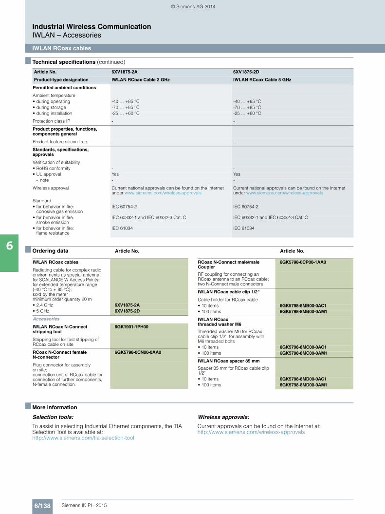
6/138 Siemens IK PI · 2015
■ Technical specifications (continued)
Industrial Wireless CommunicationIWLAN – Accessories
IWLAN RCoax cables
6 ■ Ordering data Article No. Article No.
■ More information
Selection tools:
To assist in selecting Industrial Ethernet components, the TIA Selection Tool is available at:http://www.siemens.com/tia-selection-tool
Wireless approvals:
Current approvals can be found on the Internet at: http://www.siemens.com/wireless-approvals
Article No. 6XV1875-2A 6XV1875-2D
Product-type designation IWLAN RCoax Cable 2 GHz IWLAN RCoax Cable 5 GHz
Permitted ambient conditions
Ambient temperature• during operating -40 … +85 °C -40 … +85 °C• during storage -70 … +85 °C -70 … +85 °C• during installation -25 … +60 °C -25 … +60 °C
Protection class IP - -
Product properties, functions, components general
Product feature silicon-free - -
Standards, specifications, approvals
Verification of suitability• RoHS conformity - -• UL approval Yes Yes
- note - -
Wireless approval Current national approvals can be found on the Internet under www.siemens.com/wireless-approvals
Current national approvals can be found on the Internet under www.siemens.com/wireless-approvals
Standard• for behavior in fire:
corrosive gas emissionIEC 60754-2 IEC 60754-2
• for behavior in fire: smoke emission
IEC 60332-1 and IEC 60332-3 Cat. C IEC 60332-1 and IEC 60332-3 Cat. C
• for behavior in fire:flame resistance
IEC 61034 IEC 61034
IWLAN RCoax cables
Radiating cable for complex radio environments as special antenna for SCALANCE W Access Points; for extended temperature range (-40 °C to + 85 °C); sold by the meter minimum order quantity 20 m• 2.4 GHz 6XV1875-2A• 5 GHz 6XV1875-2D
Accessories
IWLAN RCoax N-Connect stripping tool
6GK1901-1PH00
Stripping tool for fast stripping of RCoax cable on site
RCoax N-Connect female N-connector
6GK5798-0CN00-0AA0
Plug connector for assembly on site; connection unit of RCoax cable for connection of further components, N-female connection.
RCoax N-Connect male/male Coupler
6GK5798-0CP00-1AA0
RF coupling for connecting an RCoax antenna to an RCoax cable; two N-Connect male connectors
IWLAN RCoax cable clip 1/2"
Cable holder for RCoax cable• 10 items 6GK5798-8MB00-0AC1• 100 items 6GK5798-8MB00-0AM1
IWLAN RCoax threaded washer M6
Threaded washer M6 for RCoax cable clip 1/2", for assembly with M6 threaded bolts• 10 items 6GK5798-8MC00-0AC1• 100 items 6GK5798-8MC00-0AM1
IWLAN RCoax spacer 85 mm
Spacer 85 mm for RCoax cable clip 1/2"• 10 items 6GK5798-8MD00-0AC1• 100 items 6GK5798-8MD00-0AM1
Kap_06_IWC_en.book Seite 138 Dienstag, 7. Oktober 2014 1:47 13
© Siemens AG 2014

6/139Siemens IK PI · 2015
Industrial Wireless CommunicationIWLAN – Accessories
IWLAN cabling technology
6
■ Overview
A comprehensive, coordinated range of coaxial accessories is offered for flexible combination and installation of the individual IWLAN components indoors and outdoors.
This range encompasses connecting cables as well as diverse connectors, lightning protection elements, a power splitter and an attenuator.
■ Benefits
• Flexible use thanks to extensive, coordinated range • Operation also outdoors with extended temperature range
and protection against water and dust thanks to degree of protection IP65
• Components are suitable for use with SCALANCE W700 including national approvals
■ Application
RCoax/antenna connecting cables• The flexible IWLAN RCoax/antenna connecting cables are
required for connecting RCoax segments or antennas with active devices.
• The cables offer low attenuation so that the quality of the radio signal is only reduced to a minimal extent.
• All antenna cables are flame-resistant, chemical-resistant and silicone-free.
Terminating resistors• Terminating resistors are required for wireless termination of
unused antenna connections at the access points and clients.• RCoax segments must be terminated at the end with a termi-
nating resistor.
Lightning protection elements• When separate antennas are used outdoors, there is a risk of
lightning strikes. • A lightning protector can be used to prevent damage.
Cabinet feedthroughs
Together with the antenna connecting cables, the cabinet feedthroughs enable simple connection of remote antennas to the active components located in the control cabinet/box.
Attenuator
The 10 dB attenuator is always used when the transmitted power has to be reduced both in the send and receive directions. Typ-ical application areas include short RCoax segments or direc-tional wireless links, which are to be limited in extent.
Power splitter• With the help of the power splitter, the transmission power of
an access point is divided between two RCoax or antenna segments.
• This enables wireless coverage in two areas using just one access point.
Product versions
RCoax/antenna connecting cables• Pre-assembled cable lengths (0.3 m to 10 m) • Different connector types and combinations (N-Connect,
R-SMA, SMA, QMA)
Terminating resistors• TI795-1R: Terminating resistor 50 ohms for R-SMA antenna
sockets• TI795-1N: Terminating resistor 50 ohms for N-Connect
antenna sockets or RCoax segments
Lightning protection elements• LP798-2N: Maintenance-free lightning protection element for
N-Connect connections- Quarter-wave system (lambda-quarter) for the frequency
range 2 to 6 GHz- Represents a short-circuit for DC voltages so that all types of
overvoltage can be reliably diverted- Not suitable for DC infeed via the antenna cable
• LP798-1N: Lightning protection element for N-Connect connections - With gas discharge arrester for the frequency range 0 to
6 GHz for N-Connect connections- Suitable for DC infeed via the antenna cable
Cabinet feedthroughs• N-Connect female/SMA female with fastening flange for panel
thicknesses up to 5.5 mm• N-Connect female/N-Connect female without flange for panel
thicknesses up to 4.5 mm- Can also be used to connect two antenna connecting cables
Kap_06_IWC_en.book Seite 139 Dienstag, 7. Oktober 2014 1:47 13
© Siemens AG 2014

6/140 Siemens IK PI · 2015
Industrial Wireless CommunicationIWLAN – Accessories
IWLAN cabling technology
6
■ Technical specifications
Article No. 6XV1875-5AH10 6XV1875-5AH20 6XV1875-5AH50 6XV1875-5AN10
Product-type designation IWLAN RCoax/Antenna Connection Cable N-Connect Male/ Male
IWLAN RCoax/Antenna Connection Cable N-Connect Male/ Male
IWLAN RCoax/Antenna Connection Cable N-Connect Male/ Male
IWLAN RCoax/Antenna Connection Cable N-Connect Male/ Male
Acceptability for application Flexible connecting cable for connecting an antenna or RCoax cable to an access point/client
Flexible connecting cable for connecting an antenna or RCoax cable to an access point/client
Flexible connecting cable for connecting an antenna or RCoax cable to an access point/client
Flexible connecting cable for connecting an antenna or RCoax cable to an access point/client
Cable length 1 m 2 m 5 m 10 m
Electrical data
Number of electrical connections 2 2 2 2
Design of the electrical connection N-Connect/N-Connect male/male
N-Connect/N-Connect male/male
N-Connect/N-Connect male/male
N-Connect/N-Connect male/male
Transmission frequency 0 … 6 GHz 0 … 6 GHz 0 … 6 GHz 0 … 6 GHz
Attenuation per length• at 2.4 GHz typical 0.53 dB/m 0.53 dB/m 0.53 dB/m 0.53 dB/m• at 5.2 GHz typical 0.83 dB/m 0.83 dB/m 0.83 dB/m 0.83 dB/m• at 5.85 GHz typical 0.89 dB/m 0.89 dB/m 0.89 dB/m 0.89 dB/m
Return loss minimum 23 dB 23 dB 23 dB 23 dB
Impedance Nominal value 50 50 50 50
Capacity per length at 1 kHz 82 pF/m 82 pF/m 82 pF/m 82 pF/m
Relative speed 82 % 82 % 82 % 82 %
Mechanical data
Design of shield Braided shield made of tin-plated copper wires
Braided shield made of tin-plated copper wires
Braided shield made of tin-plated copper wires
Braided shield made of tin-plated copper wires
Outer diameter• of the inner conductor 1.4 mm 1.4 mm 1.4 mm 1.4 mm• of dielectric 3.8 mm 3.8 mm 3.8 mm 3.8 mm• of the cable sheath 6.3 mm 6.3 mm 6.3 mm 6.3 mm
Symmetrical tolerance of outer diameter of cable sheath
0.2 mm 0.2 mm 0.2 mm 0.2 mm
Thickness of the cable sheath 0.76 mm 0.76 mm 0.76 mm 0.76 mm
Material• of inner conductor Cu Cu Cu Cu• of dielectric polyethylene foam polyethylene foam polyethylene foam polyethylene foam• of the cable sheath FRNC FRNC FRNC FRNC
Color of the cable sheath Pastel turquoise Pastel turquoise Pastel turquoise Pastel turquoise
Bending radius• with single bend minimum
permissible32 mm 32 mm 32 mm 32 mm
• with multiple bends minimum permissible
45 mm 45 mm 45 mm 45 mm
Traction stress maximum 80 N 80 N 80 N 80 N
Weight per length 75 kg/km 75 kg/km 75 kg/km 75 kg/km
Permitted ambient conditions
Ambient temperature• during operating -40 … +80 °C -40 … +80 °C -40 … +80 °C -40 … +80 °C• during storage -40 … +80 °C -40 … +80 °C -40 … +80 °C -40 … +80 °C• during transport -40 … +80 °C -40 … +80 °C -40 … +80 °C -40 … +80 °C• during installation -25 … +80 °C -25 … +80 °C -25 … +80 °C -25 … +80 °C
Protection class IP IP68 IP68 IP68 IP68
Protection class IP note when plugged in when plugged in when plugged in when plugged in
Burning behaviour UL 1685 (Vertical tray) and UL 1581, Sec. 1090 (H)
UL 1685 (Vertical tray) and UL 1581, Sec. 1090 (H)
UL 1685 (Vertical tray) and UL 1581, Sec. 1090 (H)
UL 1685 (Vertical tray) and UL 1581, Sec. 1090 (H)
Chemical resistance to mineral oil Conditional resistance Conditional resistance Conditional resistance Conditional resistance
Radiological resistance to UV radiation
Resistant Resistant Resistant Resistant
Kap_06_IWC_en.book Seite 140 Dienstag, 7. Oktober 2014 1:47 13
© Siemens AG 2014

6/141Siemens IK PI · 2015
6
■ Technical specifications (continued)
Industrial Wireless CommunicationIWLAN – Accessories
IWLAN cabling technology
Product properties, functions, components general
Product feature• halogen-free Yes Yes Yes Yes• silicon-free Yes Yes Yes Yes
Standards, specifications, approvals
Verification of suitability• UL-registration - - - -• RoHS conformity Yes Yes Yes Yes
Article No. 6XV1875-5CE30 6XV1875-5CH10 6XV1875-5CH20 6XV1875-5CH50 6XV1875-5CN10
Product-type designation IWLAN RCoax/Antenna Connection Cable N-Connect RSMA Male/Male
IWLAN RCoax/Antenna Connection Cable N-Connect/ RSMA Male/ Male
IWLAN RCoax/Antenna Connection Cable N-Connect/ RSMA Male/ Male
IWLAN RCoax/Antenna Connection Cable N-Connect/ RSMA Male/ Male
IWLAN RCoax/Antenna Connection Cable N-Connect/ RSMA Male/ Male
Acceptability for application Flexible connecting cable for connecting an antenna or RCoax cable to an access point/client
Flexible connecting cable for connecting an antenna or RCoax cable to an access point/client
Flexible connecting cable for connecting an antenna or RCoax cable to an access point/client
Flexible connecting cable for connecting an antenna or RCoax cable to an access point/client
Flexible connecting cable for connecting an antenna or RCoax cable to an access point/client
Cable length 0.3 m 1 m 2 m 5 m 10 m
Electrical data
Number of electrical connections 2 2 2 2 2
Design of the electrical connection N-Connect/RSMA male/male
N-Connect/RSMA male/male
N-Connect/RSMA male/male
N-Connect/RSMA male/male
N-Connect/RSMA male/male
Transmission frequency 0 … 6 GHz 0 … 6 GHz 0 … 6GHz 0 … 6 GHz 0 … 6 GHz
Attenuation per length• at 2.4 GHz typical 0.53 dB/m 0.53 dB/m 0.53 dB/m 0.53 dB/m 0.53 dB/m• at 5.2 GHz typical 0.83 dB/m 0.83 dB/m 0.83 dB/m 0.83 dB/m 0.83 dB/m• at 5.85 GHz typical 0.89 dB/m 0.89 dB/m 0.89 dB/m 0.89 dB/m 0.89 dB/m
Return loss minimum 23 dB 23 dB 23 dB 23 dB 23 dB
Impedance Nominal value 50 50 50 50 50
Capacity per length at 1 kHz 82 pF/m 82 pF/m 82 pF/m 82 pF/m 82 pF/m
Relative speed 82 % 82 % 82 % 82 % 82 %
Mechanical data
Design of shield Braided shield made of tin-plated copper wires
Braided shield made of tin-plated copper wires
Braided shield made of tin-plated copper wires
Braided shield made of tin-plated copper wires
Braided shield made of tin-plated copper wires
Outer diameter• of the inner conductor 1.4 mm 1.4 mm 1.4 mm 1.4 mm 1.4 mm• of dielectric 3.8 mm 3.8 mm 3.8 mm 3.8 mm 3.8 mm• of the cable sheath 6.3 mm 6.3 mm 6.3 mm 6.3 mm 6.3 mm
Symmetrical tolerance of outer diameter of cable sheath
0.2 mm 0.2 mm 0.2 mm 0.2 mm 0.2 mm
Thickness of the cable sheath 0.76 mm 0.76 mm 0.76 mm 0.76 mm 0.76 mm
Material• of inner conductor Cu Cu Cu Cu Cu• of dielectric polyethylene foam polyethylene foam polyethylene foam polyethylene foam polyethylene foam• of the cable sheath FRNC FRNC FRNC FRNC FRNC
Color of the cable sheath Pastel turquoise Pastel turquoise Pastel turquoise Pastel turquoise Pastel turquoise
Article No. 6XV1875-5AH10 6XV1875-5AH20 6XV1875-5AH50 6XV1875-5AN10
Product-type designation IWLAN RCoax/Antenna Connection Cable N-Connect Male/ Male
IWLAN RCoax/Antenna Connection Cable N-Connect Male/ Male
IWLAN RCoax/Antenna Connection Cable N-Connect Male/ Male
IWLAN RCoax/Antenna Connection Cable N-Connect Male/ Male
Kap_06_IWC_en.book Seite 141 Dienstag, 7. Oktober 2014 1:47 13
© Siemens AG 2014

6/142 Siemens IK PI · 2015
6
■ Technical specifications (continued)
Industrial Wireless CommunicationIWLAN – Accessories
IWLAN cabling technology
Bending radius• with single bend minimum
permissible32 mm 32 mm 32 mm 32 mm 32 mm
• with multiple bends minimum permissible
45 mm 45 mm 45 mm 45 mm 45 mm
Traction stress maximum 80 N 80 N 80 N 80 N 80 N
Weight per length 75 kg/km 75 kg/km 75 kg/km 75 kg/km 75 kg/km
Permitted ambient conditions
Ambient temperature• during operating -40 … +80 °C -40 … +80 °C -40 … +80 °C -40 … +80 °C -40 … +80 °C• during storage -40 … +80 °C -40 … +80 °C -40 … +80 °C -40 … +80 °C -40 … +80 °C• during transport -40 … +80 °C -40 … +80 °C -40 … +80 °C -40 … +80 °C -40 … +80 °C• during installation -25 … +80 °C -25 … +80 °C -25 … +80 °C -25 … +80 °C -25 … +80 °C
Protection class IP IP68 IP68 IP68 IP68 IP68
Protection class IP note when plugged in when plugged in when plugged in when plugged in when plugged in
Burning behaviour UL 1685 (Vertical tray) and UL 1581, Sec. 1090 (H)
UL 1685 (Vertical tray) and UL 1581, Sec. 1090 (H)
UL 1685 (Vertical tray) and UL 1581, Sec. 1090 (H)
UL 1685 (Vertical tray) and UL 1581, Sec. 1090 (H)
UL 1685 (Vertical tray) and UL 1581, Sec. 1090 (H)
Chemical resistance to mineral oil Conditional resistance Conditional resistance Conditional resistance Conditional resistance Conditional resistance
Radiological resistance to UV radiation
Resistant Resistant Resistant Resistant Resistant
Product properties, functions, components general
Product feature• halogen-free Yes Yes Yes Yes Yes• silicon-free Yes Yes Yes Yes Yes
Standards, specifications, approvals
Verification of suitability• UL-registration - - - - -• RoHS conformity Yes Yes Yes Yes Yes
Article No. 6XV1875-5CE30 6XV1875-5CH10 6XV1875-5CH20 6XV1875-5CH50 6XV1875-5CN10
Product-type designation IWLAN RCoax/Antenna Connection Cable N-Connect RSMA Male/Male
IWLAN RCoax/Antenna Connection Cable N-Connect/ RSMA Male/ Male
IWLAN RCoax/Antenna Connection Cable N-Connect/ RSMA Male/ Male
IWLAN RCoax/Antenna Connection Cable N-Connect/ RSMA Male/ Male
IWLAN RCoax/Antenna Connection Cable N-Connect/ RSMA Male/ Male
Article No. 6XV1875-5DE30 6XV1875-5DH20 6XV1875-5JH10
Product-type designation IWLAN RCoax/Antenna Connection Cable RSMA/SMA Male/ Male
IWLAN RCoax/Antenna Connection Cable RSMA/SMA Male/ Male
IWLAN Cable QMA / N-Connect Male/Female
Acceptability for application Flexible connecting cable for connect-ing a cabinet bushing with SMA connection to an access point/client
Flexible connecting cable for connect-ing a cabinet bushing with SMA connection to an access point/client
Adapter cable for connecting an antenna with QMA connection to the flexible connecting cables
Cable length 0.3 m 2 m 1 m
Electrical data
Number of electrical connections 2 2 2
Design of the electrical connection RSMA/ SMA male/male RSMA/ SMA male/male QMA/N-Connect male/female
Transmission frequency 0 … 6 GHz 0 … 6 GHz 0 … 6 GHz
Attenuation per length• at 2.4 GHz typical 0.53 dB/m 0.53 dB/m 0.53 dB/m• at 5.2 GHz typical 0.83 dB/m 0.83 dB/m 0.83 dB/m• at 5.85 GHz typical 0.89 dB/m 0.89 dB/m 0.89 dB/m
Return loss minimum 23 dB 23 dB 23 dB
Impedance Nominal value 50 50 50
Capacity per length at 1 kHz 82 pF/m 82 pF/m 82 pF/m
Relative speed 82 % 82 % 82 %
Kap_06_IWC_en.book Seite 142 Dienstag, 7. Oktober 2014 1:47 13
© Siemens AG 2014

6/143Siemens IK PI · 2015
6
■ Technical specifications (continued)
Industrial Wireless CommunicationIWLAN – Accessories
IWLAN cabling technology
Mechanical data
Design of shield Braided shield made of tin-plated copper wires
Braided shield made of tin-plated copper wires
Braided shield made of tin-plated copper wires
Outer diameter• of the inner conductor 1.4 mm 1.4 mm 1.4 mm• of dielectric 3.8 mm 3.8 mm 3.8 mm• of the cable sheath 6.3 mm 6.3 mm 6.3 mm
Symmetrical tolerance of outer diameter of cable sheath
0.2 mm 0.2 mm 0.2 mm
Thickness of the cable sheath 0.76 mm 0.76 mm 0.76 mm
Material• of inner conductor Cu Cu Cu• of dielectric polyethylene foam polyethylene foam polyethylene foam• of the cable sheath FRNC FRNC FRNC
Color of the cable sheath Pastel turquoise Pastel turquoise Pastel turquoise
Bending radius• with single bend minimum
permissible32 mm 32 mm 32 mm
• with multiple bends minimum permissible
45 mm 45 mm 45 mm
Traction stress maximum 80 N 80 N 80 N
Weight per length 75 kg/km 75 kg/km 75 kg/km
Permitted ambient conditions
Ambient temperature• during operating -40 … +80 °C -40 … +80 °C -40 … +80 °C• during storage -40 … +80 °C -40 … +80 °C -40 … +80 °C• during transport -40 … +80 °C -40 … +80 °C -40 … +80 °C• during installation -25 … +80 °C -25 … +80 °C -25 … +80 °C
Protection class IP IP68 IP68 IP67
Protection class IP note when plugged in when plugged in when plugged in
Burning behaviour UL 1685 (Vertical tray) and UL 1581, Sec. 1090 (H)
UL 1685 (Vertical tray) and UL 1581, Sec. 1090 (H)
UL 1685 (Vertical tray) and UL 1581, Sec. 1090 (H)
Chemical resistance to mineral oil Conditional resistance Conditional resistance Conditional resistance
Radiological resistance to UV radiation
Resistant Resistant Resistant
Product properties, functions, components general
Product feature• halogen-free Yes Yes Yes• silicon-free Yes Yes Yes
Standards, specifications, approvals
Verification of suitability• UL-registration - - -• RoHS conformity Yes Yes Yes
Article No. 6XV1875-5DE30 6XV1875-5DH20 6XV1875-5JH10
Product-type designation IWLAN RCoax/Antenna Connection Cable RSMA/SMA Male/ Male
IWLAN RCoax/Antenna Connection Cable RSMA/SMA Male/ Male
IWLAN Cable QMA / N-Connect Male/Female
Kap_06_IWC_en.book Seite 143 Dienstag, 7. Oktober 2014 1:47 13
© Siemens AG 2014

6/144 Siemens IK PI · 2015
6
■ Technical specifications (continued)
Industrial Wireless CommunicationIWLAN – Accessories
IWLAN cabling technology
Article No. 6GK5795-1TN00-1AA0 6GK5795-1TR10-0AA6 6GK5798-0AP00-4CA0 6GK5798-0SN00-0EA0
Product-type designation IWLAN termination imped-ance TI795-1N N-ConnectMale
IWLAN termination imped-ance TI795-1R RSMAMale
IWLAN attenuator N-ConnectMale/Female
IWLAN Power SplitterN-ConnectFemale
Supply voltage, current consumption, power loss
Type of supply voltage - - - -
Supply voltage for DC - - - -
Consumed current maximum - - - -
Active power loss maximum - - - -
Electrical data
Number of electrical connections 1 1 2 3
Design of the electrical connection N-Connect male R-SMA male N-Connect male/ N-Connect female
N-Connect female
Transmission frequency 0 … 6 GHz 0 … 6 GHz 0 … 6 GHz 2 400 … 6 GHz
Impedance 50 50 50 50
Return loss minimum 25 dB 25 dB - 24 dB
Insertion loss maximum - - 10 dB 3.05 dB
Permitted ambient conditions
Ambient temperature• during operating -40 … +70 °C -40 … +70 °C -40 … +70 °C -25 … +110 °C• during storage -40 … +70 °C -40 … +70 °C -40 … +70 °C -25 … +110 °C• during transport -40 … +70 °C -40 … +70 °C -40 … +70 °C -25 … +110 °C
Relative humidity at 25 °C without condensation during operating maximum
Protection class IP IP 65 IP 65 - IP 67
Design, dimensions and weight
Design - - - -
Width - - - 71.4 mmHeight - - - -Depth - - - 34 mmDiameter 21 mm 9 mm 21 mm -Length 34.5 mm 15 mm 45.7 mm 131.4 mm
Net weight 45 g 5 g 64 g 937 g
Installation - - - -
Version of the swap medium• C-PLUG - - - -• KEY-PLUG - - - -
Kap_06_IWC_en.book Seite 144 Dienstag, 7. Oktober 2014 1:47 13
© Siemens AG 2014

6/145Siemens IK PI · 2015
6
■ Technical specifications (continued)
Industrial Wireless CommunicationIWLAN – Accessories
IWLAN cabling technology
Article No. 6GK5798-2LP00-2AA6 6GK5798-2LP10-2AA6
Product-type designation Lightning Protector LP798-1N Lightning Protector LP798-2N
Electrical data
Impedance 50 50
Mechanical data
Design of the plug-in connection female / female female / female
Ambient temperature• during operating -40 … +85 °C -40 … +85 °C• during storage -40 … +85 °C -40 … +85 °C• during transport -40 … +85 °C -40 … +85 °C
Protection class IP IP67 IP68
Design, dimensions and weight
Width 54.8 mm 89.6 mmHeight - -Depth - -Diameter 22.8 mm 29 mm
Net weight 50 g 80 g
Article No. 6GK5798-0PT00-2AA0 6GK5798-2PP00-2AA6 6GK5798-0CP00-1AA0 6GK5798-1CS00-4AA0
Product-type designation IWLAN panel feedthroughN-Connect/SMA Female/Female
IWLAN panel feedthroughN-Connect/N-Connect Female/Female
IWLAN coupler N-Connect-Male/Male
IWLAN angled adapterRSMA/RSMAmale/female
Electrical data
Number of electrical connections 2 2 2 2
Design of the electrical connection N-Connect female/SMA female
N-Connect female/N-Connect female
N-Connect male/N-Connect male
R-SMA male / R-SMA female
Transmission frequency 0 … 6 GHz 0 … 11 000 MHz 0 … 6 GHz 0 … 6 GHz
Impedance 50 50 50 50
Return loss minimum - - 0.1 dB -
Insertion loss maximum - - - -
Permitted ambient conditions
Ambient temperature• during operating -40 … +70 °C -30 … +100 °C -40 … +70 °C -• during storage -40 … +70 °C -30 … +100 °C -40 … +70 °C -• during transport -40 … +70 °C -30 … +100 °C -40 … +70 °C -
Relative humidity at 25 °C without condensation during operating maximum
-
Protection class IP - IP 68 - -
Design, dimensions and weight
Design - - - -
Width 25.4 mm - - 17 mmHeight 25.4 mm - - 15 mmDepth - - - -Diameter - 20.7 mm 20.8 mm -Length 31.3 mm 38 mm 36.4 mm -
Net weight 35 g 55 g 60 g -
Installation for wall thickness max. 5.5 mm
for wall thickness max. 4.5 mm
- -
Kap_06_IWC_en.book Seite 145 Dienstag, 7. Oktober 2014 1:47 13
© Siemens AG 2014

6/146 Siemens IK PI · 2015
Industrial Wireless CommunicationIWLAN – Accessories
IWLAN cabling technology
6
■ Ordering data Article No. Article No.
IWLAN RCoax/antenna N-Connect/R-SMA Male/male flexible connection cable
Flexible connecting cable for con-necting an RCoax cable or antenna to a SCALANCE W-700 access point with R-SMA connections;pre-assembled with two connections, N-Connect male and R-SMA male• 0.3 m 6XV1875-5CE30• 1 m 6XV1875-5CH10• 2 m 6XV1875-5CH20• 5 m 6XV1875-5CH50• 10 m 6XV1875-5CN10
IWLAN RCoax/antenna N-Connect male/male Flexible connection cable
Flexible connecting cable for con-necting an RCoax cable or antenna to a SCALANCE W-700 access point with N-Connect connections; pre-assembled with two N-Connect male connections• 1 m 6XV1875-5AH10• 2 m 6XV1875-5AH20• 5 m 6XV1875-5AH50• 10 m 6XV1875-5AN10
IWLAN RCoax/antenna QMA/N-Connect male/female Flexible connection cable
Adapter cable for connecting a MIMO antenna with QMA connec-tions to the flexible connecting cables; assembled with two connections QMA male and N-Connect female; scope of delivery: 3 units• 1 m 6XV1875-5JH10
IWLAN RCoax/antenna R-SMA/SMA male/male Flexible connection cable
Flexible cable for connecting an active device to components with RSMA and SMA connections, e.g. cabinet bushing; pre-assembled with two R-SMA male to SMA male connectors• 0.3 m 6XV1875-5DE30• 2 m 6XV1875-5DH20
IWLAN RCoax/antenna N-Connect male termination impedance TI795-1N
6GK5795-1TN00-1AA0
Terminating resistor for RCoax cable and open wireless interfaces on SCALANCE W-700 devices with N-Connect connections,impedance 50 ohms, N-male connection; IP65 (-40 to +70 °C)
IWLAN RCoax/antenna RSMA male termination impedance TI795-1R
6GK5795-1TR10-0AA6
Terminating resistor for open wireless interfaces on SCALANCE W-700 devices with RSMA connections,impedance 50 ohms, RSMA male connection; IP65 (-40 to +70 °C); 3 units
Lightning protector LP798-1N 6GK5798-2LP00-2AA6
Lightning protector with N/N female/female connection, IP67 (-40 to +85 °C),frequency range: 0 to 6 GHz
Lightning protector LP798-2N 6GK5798-2LP10-2AA6
Lightning protectorwith N/N female/female connection, IP68 (-40 to +85 °C), Quarter Wave technology,frequency range: 2 to 6 GHz
IWLAN RCoax/antenna N-Connect female power splitter
6GK5798-0SN00-0EA0
2-way cable splitter, Y-element for splitting the RCoax cable or for using two antennas on one wireless interface
IWLAN RCoax/antennaN-Connect male/male coupler
6GK5798-0CP00-1AA0
HF coupling for connecting two RCoax cables;two N-Connect male connectors
IWLAN angled adapter RSMA/RSMA male/female
6GK5798-1CS00-4AA0
HF angled adapter 90 for connecting antennas or antenna connection cables to devices with an RSMA connector
IWLAN RCoax/antennaN-Connect male/female attenuator
Attenuator with N-Connect male/N-Connect female connectors• 10 dB 6GK5798-0AP00-4CA0
IWLAN RCoax/antenna N-Connect/SMAfemale/female panel bushing
6GK5798-0PT00-2AA0
Cabinet bushing with fastening flange for wall thicknesses up to 5.5 mm, SMA female and N-Connect female connections
IWLAN RCoax/antenna N-Connect/N-Connectfemale/female panel bushing
6GK5798-2PP00-2AA6
Cabinet bushing for wall thicknesses up to 4.5 mm, two N-Connect female connections
Kap_06_IWC_en.book Seite 146 Dienstag, 7. Oktober 2014 1:47 13
© Siemens AG 2014

6/147Siemens IK PI · 2015
Industrial Wireless CommunicationIWLAN – Accessories
IWLAN cabling technology
6
■ More information
Selection tools:
To assist in selecting Industrial Ethernet components, the TIA Selection Tool is available at: http://www.siemens.com/tia-selection-tool
Cabling range:
You can order components supplementary to the SIMATIC NET cabling range from your local contact. Technical advice on this subject is available from:
J. Hertlein I IA SC CI PRM 4 Phone +49 (911) 750-4465 E-mail: [email protected]
Kap_06_IWC_en.book Seite 147 Dienstag, 7. Oktober 2014 1:47 13
© Siemens AG 2014

6/148 Siemens IK PI · 2015
Industrial Wireless CommunicationIWLAN – Accessories
KEY-PLUG W700
6
■ Overview
• Swap medium with which iFeatures are enabled • If a fault occurs, it allows fast and simple device replacement
of SCALANCE W components without a PG • Can be used in all SCALANCE W700 IEEE 802.11n products
with a PLUG compartment• For the automatic backup of configuration data
■ Benefits
• Fast and simple replacement of SCALANCE W components without reconfiguration of the spare part.
• The device can be replaced without the need for specially trained personnel or a programming device or PC.
• The downtimes of network segments and connected Industrial Ethernet nodes can therefore be minimized if a fault occurs.
■ Application
The KEY-PLUG stores the configuration data of a SCALANCE W component. In addition, the iFeatures are enabled.
In addition to this, if there is a fault on a module, the module can be replaced simply and quickly without needing to reconfigure the replacement device and without specially trained personnel. If a device needs to be replaced, the KEY-PLUG is simply re-moved from the failed component and plugged into the replace-ment device. The replacement device installed in the network now starts up automatically with the same device configuration as the failed device.
■ Design
The KEY-PLUG has degree of protection IP20. The degree of protection of IP65 components is ensured by the design of the target device. The KEY-PLUG is inserted in the PLUG compart-ment of the SCALANCE W component.
■ Mode of operation
During startup, the device automatically backs up the configura-tion data on a KEY-PLUG (as-supplied from the factory) plugged into a SCALANCE W component. Changes to the configuration during operation are also saved on the KEY-PLUG without any additional operator intervention being necessary.
During startup, an unconfigured device automatically loads the configuration data from an inserted KEY-PLUG that has been written to provided the data was written by a compatible device type.
Diagnostics
Incorrect use of the KEY-PLUG, such as inserting a KEY-PLUG containing the configuration of a different device group or general malfunctions of the KEY-PLUG are indicated by diagnostics mechanisms of the host device (LEDs, SNMP, Web based Management, etc.).
Kap_06_IWC_en.book Seite 148 Dienstag, 7. Oktober 2014 1:47 13
© Siemens AG 2014

6/149Siemens IK PI · 2015
Industrial Wireless CommunicationIWLAN – Accessories
KEY-PLUG W700
6
■ Integration
Supported products
IWLAN access points • SCALANCE W780• SCALANCE W780 EEC• SCALANCE W770• SCALANCE W770 EEC
IWLAN client modules• SCALANCE W740• SCALANCE W730
1) only if a dual access point is used
Which KEY-PLUG do I use for which device?• W780 = KEY-PLUG W780 iFeatures• W740 = KEY-PLUG W740 iFeatures
■ Technical specifications ■ Ordering data Article No.
Device type iPCF AP mode
iPCF Client mode
iPCF-MC AP mode
iPCF-MC Client mode
iREF AP mode
SCALANCE W730 W740/W780 W740/W780
SCALANCE W740 W740/W780 W740/W780
SCALANCE W770 W780 W740/W780 W740/W780 W780
SCALANCE W780 W780 W740/W780 W780 1) W740/W780 W780
KEY-PLUG
Power supply via terminal device
Power loss 0.015 mW
Installation Can be plugged into C-PLUG slot
Constructional design• Dimensions (W x H x D) in mm 24.3 x 17 x 8.1• Approx. weight 5 g
Memory capacity 256 MB
Degree of protection IP20
KEY-PLUG W780 iFeatures 6GK5907-8PA00
Swap medium for enabling additional iFeatures, for simple device replacement if a fault occurs, and for storing configuration data. Can be used in SCALANCE W access points with a PLUG compartment
KEY-PLUG W740 iFeatures 6GK5907-4PA00
Swap medium for enabling additional iFeatures, for simple device replacement if a fault occurs, and for storing configuration data. Can be used in SCALANCE W client modules with a PLUG compartment
Kap_06_IWC_en.book Seite 149 Dienstag, 7. Oktober 2014 1:47 13
© Siemens AG 2014

6/150 Siemens IK PI · 2015
Industrial Wireless CommunicationIWLAN – Accessories
Power Supply PS791-2DC and PS791-2AC
6
■ Overview
PS791-2DC power supply adapter• DC/DC power supply unit for input voltages from 12 to 24 V DC
and an output voltage of 18 V DC for all SCALANCE W786 devices
PS791-2AC power supply adapter• AC/DC power supply unit for input voltages from
100 to 240 V AC and an output voltage of 18 V DC for all SCALANCE W786 devices
■ Benefits
• The PS791-2DC and PS791-2AC power supply adapters are designed specially for the SCALANCE W786 access points and are integrated direct into these
• Global application due to wide input voltage range• High reliability as power supply is short-circuit proof, secure
against no-load operation and is able to bridge short breaks in the mains power
• When the power supply adapter and Power-over-Ethernet (PoE) are used, redundant power supply of the access points can be achieved
■ Design
• Integral power supply adapter for SCALANCE W786 • Fan-free design• Operating temperatures from -40 °C to +60 °C• Resistant to condensation
Kap_06_IWC_en.book Seite 150 Dienstag, 7. Oktober 2014 1:47 13
© Siemens AG 2014

6/151Siemens IK PI · 2015
Industrial Wireless CommunicationIWLAN – Accessories
Power Supply PS791-2DC and PS791-2AC
6
■ Technical specifications
■ Ordering data Article No.
Article No. 6GK5791-2DC00-0AA0 6GK5791-2AC00-0AA0
Product type designation Power supply PS791-2DC Power supply PS791-2AC
Interfaces • Infeed: 4-pin screw terminal for DC Power • Infeed: 3-pin screw terminal for AC Power
• Output voltage: 4-pin connector • Output voltage: 4-pin connector
Input voltage 12 ... 24 V DC (min. 9 V DC, max. 32 V DC) safety extra-low voltage (SELV)
100 ... 240 V AC, 45 ... 65 Hz
Output voltage 18 V DC 18 V DC
Output power 14.4 W 14.4 W
Mains buffering – > 20 ms
Permissible ambient conditions• Operating temperature -40 °C ... +70 °C -40 °C ... +60 °C
Approvals EMC: EN 61000-6-2:2005, EN 61000-6-3:2007
EMC: EN 61000-6-2:2005, EN 61000-6-3:2007
Safety regulations EN 60950, UL 60950-1 EN 60950, UL 60950-1
Protection class VDE 0805, VDE 0100 VDE 0805, VDE 0100
Degree of protection IP65 IP65
Dimensions (W x H x D) in mm 133 x 45 x 30 mm 133 x 45 x 30 mm
Assembly Installation in SCALANCE W786 and HiPath Wireless Outdoor Access Points
Installation in SCALANCE W786 and HiPath Wireless Outdoor Access Points
Weight 223 g 209 g
Power supply PS791-2DC 6GK5791-2DC00-0AA0
24 V DC power supply for installation in SCALANCE W-786 products; operating instructionsin German/English
Power supply PS791-2AC 6GK5791-2AC00-0AA0
110 V AC to 230 V AC power supply for installation in the SCALANCE W-786 products; operating instructions German/English
Kap_06_IWC_en.book Seite 151 Dienstag, 7. Oktober 2014 1:47 13
© Siemens AG 2014

6/152 Siemens IK PI · 2015
Industrial Wireless CommunicationWireless Devices
SIMATIC Mobile Panel 277(F) IWLAN
6
■ Overview
SIMATIC Mobile Panel 277(F) IWLAN
■ Function
• Input/output fields for displaying and changing of process values.
• Function keys are used for directly triggering functions and actions. Up to 16 functions can be configured simultaneously on function keys. The function keys can also be used directly as PROFINET IO. The function keys can also be reconfigured as system keys. A frequently used function such as "Acknowledge alarm" can thus be assigned to a function key.
• Auxiliary operator controlssuch as handwheels, key switches and illuminated pushbuttons can be assigned with a variable or as a direct actuation via PROFINET IO (direct keys).
• Buttons are used for direct triggering of functions and actions. Up to 16 functions can be configured simultaneously on buttons.
• Graphics can be used as symbols instead of text for "labeling" function keys or buttons. They can also be used as full-screen background images. In the configuration software, a comprehensive library is available containing graphics and a wide variety of objects. All editors with an OLE interface can be used as graphics editors (such as PaintShop, Designer or CorelDraw).
• Vector graphics; simple geometric basic forms (e.g. lines, circles and rectangles) can be created directly in the configuration software.
• Text fields for labeling function keys, process displays, and process values in any font size.
• Trend views and bars are used for the graphic display of dynamic values.
• Display selection from the controller permits operator prompting from the controller.
• Presentation of HTML documents with MS Pocket Internet Explorer.
• Visual Basic Script, flexibility thanks to the implementation of new functions including linking to variables (comparison operations, loops, etc.).
• Language switching 16 online languages, 32 configuration languages incl. Asiatic and Cyrillic character sets - Language-dependent texts and graphics
• User administration (security) - User-oriented access protection according to requirements
of specific sectors - Authentication with user name and password - User-group-specific rights
• Signaling system - Discrete and analog alarms (edge alarms) as well as the
ALARM_S message frame procedure for SIMATIC S7 - Freely definable message classes (e.g. status/fault
messages) for definition of acknowledgment response and display of alarm events
• Message buffer - Non-volatile, maintenance-free and battery-free message
buffer. The messages remain stored when the mobile panel has the battery removed as well
• Recipe management - With additional data storage
(on optional MultiMedia Card/SD Card) - Online/offline processing on the panel - Storage of recipe data in standard Windows format (CSV) - External processing using standard tools such as Excel and
Access is possible • Help texts
for process images, messages and variables. • Arithmetic functions • Limit value monitoring
for reliable process control of inputs and outputs. • Indicator light
for machine and plant status indication. • Scheduler
for cyclic function processing. • Dynamic positioning of objects and dynamic showing/hiding
of objects • Permanent window and template concept
- Creation of screen templates • Simple maintenance and configuration thanks to:
- Backup and restore of the project, operating system, recipe data records and firmware on the optional standard Multimedia Card/SD Card
- Backup and restoration of configuration, operating system, recipe data sets and firmware on a PC using ProSave
- Project transfer/return transfer via PROFINET/WLAN- Automatic transfer detection - Individual brightness setting- Project simulation directly on the configuration computer
• WinCC flexible options - Sm@rtService for remote operator control and monitoring of
SIMATIC HMI systems based on TCP/IP networks - Sm@rtAccess for communication between HMI systems
based on TCP/IP networks. Remote access to recipe data records, passwords and HMI system-specific information, and much more. (Mobile Panel 277F IWLAN as server: View only)
- OPC server: Communication with applications (e.g. MES, ERP, or applications in the office sector) from various manufacturers (see HMI software/runtime software SIMATIC WinCC flexible/WinCC flexible RT options)
- Audit
Kap_06_IWC_en.book Seite 152 Dienstag, 7. Oktober 2014 1:47 13
© Siemens AG 2014

6/153Siemens IK PI · 2015
■ Function (continued)
Industrial Wireless CommunicationWireless Devices
SIMATIC Mobile Panel 277(F) IWLAN
6
Configuration
Configuration is carried out with the SIMATIC WinCC flexible Standard or Advanced configuration software (see SIMATIC WinCC flexible HMI software/engineering software). SIMATIC WinCC flexible is the logical further development of the field-proven ProTool family. Projects generated using ProTool can be easily migrated to WinCC flexible. If WinCC flexible is started directly from SIMATIC Manager, data in STEP 7 can be accessed directly when the panel is configured. Duplicated data input and data management is, therefore, avoided.
IWLAN infrastructure
The required IWLAN infrastructure is set up using the SCALANCE W-700 IWLAN Access Points, preferably with the SCALANCE W-700 variant that has two wireless cards built into the device (Dual Access Point) and KEY-PLUG W700 iFeatures which supports the application options of the Mobile Panel 277(F) IWLAN.
The iPCF-MC functionality (rapid roaming = fast, uninterrupted switchover between multiple access points) is only available with panels in version V2 or higher.
The Access Point provides an Industrial Ethernet interface for connection to the wired network.
In addition to a reliable radio link, the SCALANCE W-700 Access Points stand out due to their optimum support of standardized IT mechanisms:• IEEE 802.11b/ g/ a/ h for different frequency ranges• IEEE 802.11e for multimedia, wireless multimedia (WMM) 1)
• IEEE 802.11i for security 1)
• Construction of redundant networks with the Rapid Spanning Tree Protocol (RSTP)
• Virtual networks (VLAN) to logically separate, for example, different user groups
• Sending the log entries of the SCALANCE W devices to a Syslog server
Onlythe wireless approvals printed on the Mobile Panel are binding. The RF approvals planned for all SIMATIC products can be viewed at http://www.siemens.com/wireless-approvals.
1) Not supported by Mobile Panel Wireless
■ Integration
The SIMATIC Mobile Panel 277(F) IWLAN communicates via the WLAN Standard IEEE 802.11 a(b/g) via PROFINET. The Mobile Panel 277F IWLAN devices also support PROFIsafe communication.
There are five device variants with V2:
For mobile operation and monitoring via WLAN:• Mobile Panel 277 IWLAN V2• Mobile Panel 277 IWLAN V2 with handwheel, key switch and
illuminated pushbuttons
As fail-safe device for safety-oriented operation as well:• Mobile Panel 277F IWLAN V2 with acknowledgement button
and emergency stop button• Mobile Panel 277F IWLAN V2 with acknowledgement button,
emergency stop button, handwheel, key switch and illumi-nated pushbuttons
• Mobile Panel 277F IWLAN RFID Tag (for V2 only)
For the versions Mobile Panel 277F IWLAN (PROFIsafe), the following system prerequisites apply:• The Mobile Panel must be connected as a safe device
(PROFIsafe, Distributed Safety)• Use of a SIMATIC F-CPU
= Recommended
! = Requirement
– = Not required
The Mobile Panel 277(F) IWLAN can be connected to:• SIMATIC S7-200/300/400 (one F-CPU required for integrating
the Mobile Panel 277F IWLAN and SIMOTION (Mobile Panel 277 IWLAN V2 or higher, or Mobile Panel 277F IWLAN V2 or higher (WinCC flexible 2008 SP3 or higher))
Note:
Further information can be found under "System interfaces". The Function Manuals "Fail-Safe Operation of the Mobile Panel 277F IWLAN" are available for downloading in English, German, and Japanese.
http://support.automation.siemens.com/WW/view/en/31255853
SIMATIC Mobile Panel 5 GHz frequency band (IEEE 802.11a)
SIMATIC F-CPU (Distributed Safety)
277 IWLAN Only WLAN utilization (HMI)
–
When using transponders
! –
When using Profinet IO
–
277F IWLAN(fail-safe)
– –
!–
!277F IWLAN(RFID Tag)(fail-safe)
!
Kap_06_IWC_en.book Seite 153 Dienstag, 7. Oktober 2014 1:47 13
© Siemens AG 2014
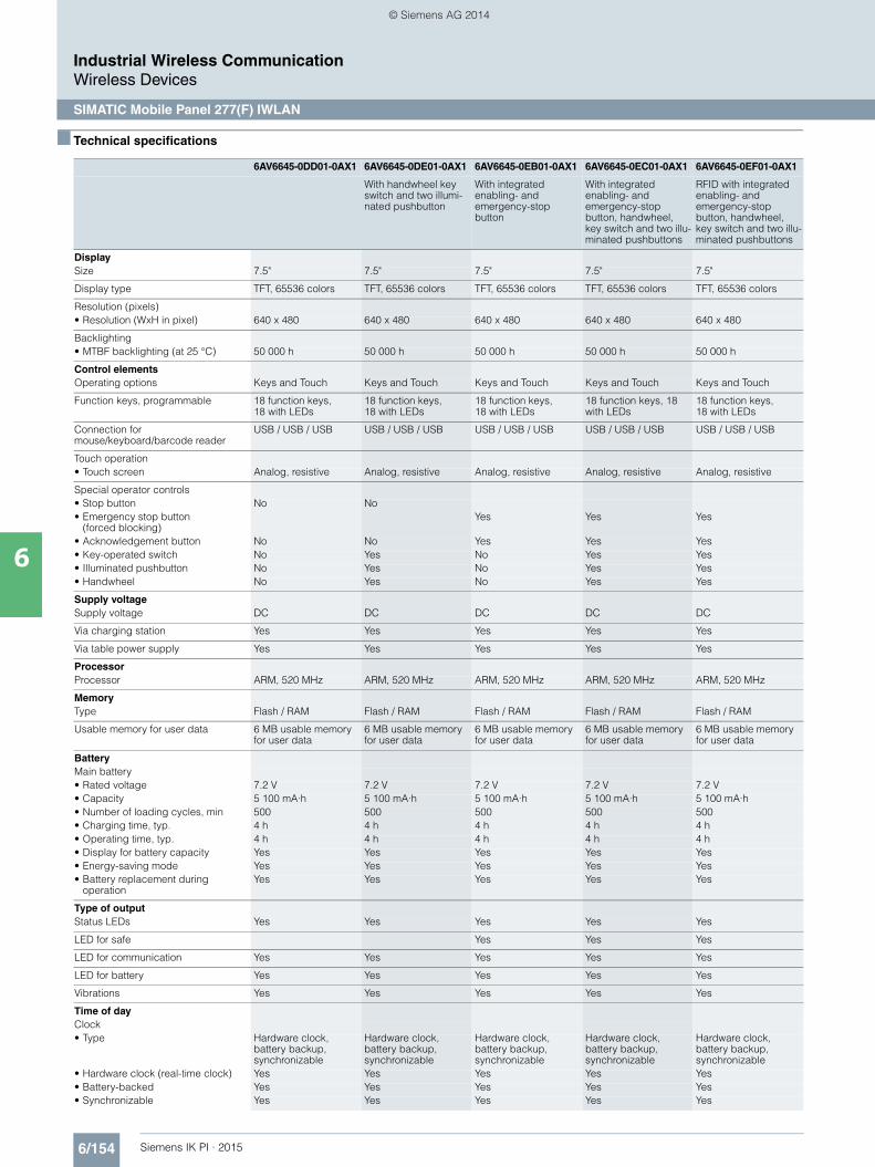
6/154 Siemens IK PI · 2015
Industrial Wireless CommunicationWireless Devices
SIMATIC Mobile Panel 277(F) IWLAN
6
■ Technical specifications
6AV6645-0DD01-0AX1 6AV6645-0DE01-0AX1 6AV6645-0EB01-0AX1 6AV6645-0EC01-0AX1 6AV6645-0EF01-0AX1
With handwheel key switch and two illumi-nated pushbutton
With integrated enabling- and emergency-stop button
With integrated enabling- and emergency-stop button, handwheel, key switch and two illu-minated pushbuttons
RFID with integrated enabling- and emergency-stop button, handwheel, key switch and two illu-minated pushbuttons
DisplaySize 7.5" 7.5" 7.5" 7.5" 7.5"
Display type TFT, 65536 colors TFT, 65536 colors TFT, 65536 colors TFT, 65536 colors TFT, 65536 colors
Resolution (pixels)• Resolution (WxH in pixel) 640 x 480 640 x 480 640 x 480 640 x 480 640 x 480
Backlighting• MTBF backlighting (at 25 °C) 50 000 h 50 000 h 50 000 h 50 000 h 50 000 h
Control elementsOperating options Keys and Touch Keys and Touch Keys and Touch Keys and Touch Keys and Touch
Function keys, programmable 18 function keys, 18 with LEDs
18 function keys, 18 with LEDs
18 function keys, 18 with LEDs
18 function keys, 18 with LEDs
18 function keys, 18 with LEDs
Connection for mouse/keyboard/barcode reader
USB / USB / USB USB / USB / USB USB / USB / USB USB / USB / USB USB / USB / USB
Touch operation• Touch screen Analog, resistive Analog, resistive Analog, resistive Analog, resistive Analog, resistive
Special operator controls• Stop button No No• Emergency stop button
(forced blocking)Yes Yes Yes
• Acknowledgement button No No Yes Yes Yes• Key-operated switch No Yes No Yes Yes• Illuminated pushbutton No Yes No Yes Yes• Handwheel No Yes No Yes Yes
Supply voltageSupply voltage DC DC DC DC DC
Via charging station Yes Yes Yes Yes Yes
Via table power supply Yes Yes Yes Yes Yes
ProcessorProcessor ARM, 520 MHz ARM, 520 MHz ARM, 520 MHz ARM, 520 MHz ARM, 520 MHz
MemoryType Flash / RAM Flash / RAM Flash / RAM Flash / RAM Flash / RAM
Usable memory for user data 6 MB usable memory for user data
6 MB usable memory for user data
6 MB usable memory for user data
6 MB usable memory for user data
6 MB usable memory for user data
BatteryMain battery• Rated voltage 7.2 V 7.2 V 7.2 V 7.2 V 7.2 V• Capacity 5 100 mA·h 5 100 mA·h 5 100 mA·h 5 100 mA·h 5 100 mA·h• Number of loading cycles, min 500 500 500 500 500• Charging time, typ. 4 h 4 h 4 h 4 h 4 h• Operating time, typ. 4 h 4 h 4 h 4 h 4 h• Display for battery capacity Yes Yes Yes Yes Yes• Energy-saving mode Yes Yes Yes Yes Yes• Battery replacement during
operationYes Yes Yes Yes Yes
Type of outputStatus LEDs Yes Yes Yes Yes Yes
LED for safe Yes Yes Yes
LED for communication Yes Yes Yes Yes Yes
LED for battery Yes Yes Yes Yes Yes
Vibrations Yes Yes Yes Yes Yes
Time of dayClock• Type Hardware clock,
battery backup, synchronizable
Hardware clock, battery backup, synchronizable
Hardware clock, battery backup, synchronizable
Hardware clock, battery backup, synchronizable
Hardware clock, battery backup, synchronizable
• Hardware clock (real-time clock) Yes Yes Yes Yes Yes• Battery-backed Yes Yes Yes Yes Yes• Synchronizable Yes Yes Yes Yes Yes
Kap_06_IWC_en.book Seite 154 Dienstag, 7. Oktober 2014 1:47 13
© Siemens AG 2014

6/155Siemens IK PI · 2015
6
■ Technical specifications (continued)
Industrial Wireless CommunicationWireless Devices
SIMATIC Mobile Panel 277(F) IWLAN
InterfacesInterfaces 1 x Ethernet (RJ45) 1 x Ethernet (RJ45) 1 x Ethernet (RJ45) 1 x Ethernet (RJ45) 1 x Ethernet (RJ45)
Number of USB interfaces 1 1 1 1 1
USB port 1 x USB 1 x USB 1 x USB 1 x USB 1 x USB
Multi Media Card slot 1 MMC/SD card slot 1 MMC/SD card slot 1 MMC/SD card slot 1 MMC/SD card slot 1 MMC/SD card slot
Industrial Ethernet• Industrial Ethernet interface 1 x Ethernet (RJ45) 1 x Ethernet (RJ45) 1 x Ethernet (RJ45) 1 x Ethernet (RJ45) 1 x Ethernet (RJ45)
WLAN• Wireless LAN Yes Yes Yes Yes Yes• Supports rapid roaming Yes Yes Yes Yes Yes
ProtocolsPROFINET Yes Yes Yes Yes Yes
Supports protocol for PROFINET IO Yes Yes Yes Yes Yes
Supports protocol for PROFIsafe No No Yes Yes Yes
EMCEmission of radio interference acc. to EN 55 011• Emission of radio interferences
acc. to EN 55 011 (limit class A)Yes; The product is designed for use in industrial environ-ments. When used in residential areas, the emission of radio inter-ference according to limit class B of EN 55011 must be ensured. For further information refer to the user documentation
Yes; The product is designed for use in industrial environ-ments. When used in residential areas, the emission of radio inter-ference according to limit class B of EN 55011 must be ensured. For further information refer to the user documentation
Yes; The product is designed for use in industrial environ-ments. When used in residential areas, the emission of radio inter-ference according to limit class B of EN 55011 must be ensured. For further information refer to the user documentation
Yes; The product is designed for use in industrial environ-ments. When used in residential areas, the emission of radio inter-ference according to limit class B of EN 55011 must be ensured. For further information refer to the user documentation
Yes; The product is designed for use in industrial environ-ments. When used in residential areas, the emission of radio inter-ference according to limit class B of EN 55011 must be ensured. For further information refer to the user documentation
Degree and class of protectionIP65 enclosure Yes Yes Yes Yes Yes
Standards, approvals, certificatesCertifications CE, cULus, C-TICK CE, cULus, C-TICK CE, cULus, C-TICK CE, cULus, C-TICK CE, cULus, C-TICK
CE mark Yes Yes Yes Yes Yes
cULus Yes Yes Yes Yes Yes
RCM (former C-TICK) Yes Yes Yes Yes Yes
TÜV safety certification Yes Yes Yes
Highest safety class achievable in safety mode• Performance level
according to EN ISO 13849-1:2008e e e
• SIL according to IEC 61508:2010 SIL 3 SIL 3 SIL 3
Ambient conditionsDrop height 1.2 m 1.2 m 1.2 m 1.2 m 1.2 m
Operating temperature• Operation 0 °C to +40 °C 0 °C to +40 °C 0 °C to +40 °C 0 °C to +40 °C 0 °C to +40 °C
Storage/transport temperature• Transport, storage -20 °C to +60 °C -20 °C to +60 °C -20 °C to +60 °C -20 °C to +60 °C -20 °C to +60 °C
Relative humidity• max. relative humidity 80 % 80 % 80 % 80 % 80 %
Operating systemsOperating system Windows CE Windows CE Windows CE Windows CE Windows CE
LanguagesOnline languages• Number of online/runtime
languages16 16 16 16 16
6AV6645-0DD01-0AX1 6AV6645-0DE01-0AX1 6AV6645-0EB01-0AX1 6AV6645-0EC01-0AX1 6AV6645-0EF01-0AX1
With handwheel key switch and two illumi-nated pushbutton
With integrated enabling- and emergency-stop button
With integrated enabling- and emergency-stop button, handwheel, key switch and two illu-minated pushbuttons
RFID with integrated enabling- and emergency-stop button, handwheel, key switch and two illu-minated pushbuttons
Kap_06_IWC_en.book Seite 155 Dienstag, 7. Oktober 2014 1:47 13
© Siemens AG 2014
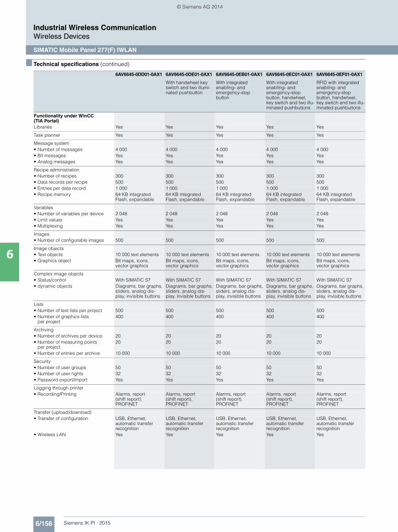
6/156 Siemens IK PI · 2015
6
■ Technical specifications (continued)
Industrial Wireless CommunicationWireless Devices
SIMATIC Mobile Panel 277(F) IWLAN
Functionality under WinCC (TIA Portal)Libraries Yes Yes Yes Yes Yes
Task planner Yes Yes Yes Yes Yes
Message system• Number of messages 4 000 4 000 4 000 4 000 4 000• Bit messages Yes Yes Yes Yes Yes• Analog messages Yes Yes Yes Yes Yes
Recipe administration• Number of recipes 300 300 300 300 300• Data records per recipe 500 500 500 500 500• Entries per data record 1 000 1 000 1 000 1 000 1 000• Recipe memory 64 KB integrated
Flash, expandable64 KB integrated Flash, expandable
64 KB integrated Flash, expandable
64 KB integrated Flash, expandable
64 KB integrated Flash, expandable
Variables• Number of variables per device 2 048 2 048 2 048 2 048 2 048• Limit values Yes Yes Yes Yes Yes• Multiplexing Yes Yes Yes Yes Yes
Images• Number of configurable images 500 500 500 500 500
Image objects• Text objects 10 000 text elements 10 000 text elements 10 000 text elements 10 000 text elements 10 000 text elements• Graphics object Bit maps, icons,
vector graphicsBit maps, icons, vector graphics
Bit maps, icons, vector graphics
Bit maps, icons, vector graphics
Bit maps, icons, vector graphics
Complex image objects• Status/control With SIMATIC S7 With SIMATIC S7 With SIMATIC S7 With SIMATIC S7 With SIMATIC S7• dynamic objects Diagrams, bar graphs,
sliders, analog dis-play, invisible buttons
Diagrams, bar graphs, sliders, analog dis-play, invisible buttons
Diagrams, bar graphs, sliders, analog dis-play, invisible buttons
Diagrams, bar graphs, sliders, analog dis-play, invisible buttons
Diagrams, bar graphs, sliders, analog dis-play, invisible buttons
Lists• Number of text lists per project 500 500 500 500 500• Number of graphics lists
per project400 400 400 400 400
Archiving• Number of archives per device 20 20 20 20 20• Number of measuring points
per project20 20 20 20 20
• Number of entries per archive 10 000 10 000 10 000 10 000 10 000
Security• Number of user groups 50 50 50 50 50• Number of user rights 32 32 32 32 32• Password export/import Yes Yes Yes Yes Yes
Logging through printer• Recording/Printing Alarms, report
(shift report), PROFINET
Alarms, report (shift report), PROFINET
Alarms, report (shift report), PROFINET
Alarms, report (shift report), PROFINET
Alarms, report (shift report), PROFINET
Transfer (upload/download)• Transfer of configuration USB, Ethernet,
automatic transfer recognition
USB, Ethernet, automatic transfer recognition
USB, Ethernet, automatic transfer recognition
USB, Ethernet, automatic transfer recognition
USB, Ethernet, automatic transfer recognition
• Wireless LAN Yes Yes Yes Yes Yes
6AV6645-0DD01-0AX1 6AV6645-0DE01-0AX1 6AV6645-0EB01-0AX1 6AV6645-0EC01-0AX1 6AV6645-0EF01-0AX1
With handwheel key switch and two illumi-nated pushbutton
With integrated enabling- and emergency-stop button
With integrated enabling- and emergency-stop button, handwheel, key switch and two illu-minated pushbuttons
RFID with integrated enabling- and emergency-stop button, handwheel, key switch and two illu-minated pushbuttons
Kap_06_IWC_en.book Seite 156 Dienstag, 7. Oktober 2014 1:47 13
© Siemens AG 2014

6/157Siemens IK PI · 2015
6
■ Technical specifications (continued)
Industrial Wireless CommunicationWireless Devices
SIMATIC Mobile Panel 277(F) IWLAN
Process coupling• Connection to controller S7-200, S7- 300/400
see section on "System interfaces"
S7-200, S7- 300/400 see section on "System interfaces"
S7-200, S7- 300/400 see section on "System interfaces"
S7-200, S7- 300/400 see section on "System interfaces"
S7-200, S7- 300/400 see section on "System interfaces"
• S7-1200 Yes Yes No No No• S7-1500 Yes Yes No; Available soon No; Available soon No; Available soon• Zones Yes Yes Yes Yes
- Number of zones per project, max.
254 254 254 254
- Number of transpondersfor zones per project, max.
255 255 255 255
• Effective range Yes Yes Yes- Number of effective ranges
per project, max.127 127 127
- Number of transpondersfor effective ranges per project, max.
127 127
• Transponder Yes Yes Yes Yes- Number of transponders
per project, max.256 256 256 256
- Adjustable distance range Yes Yes Yes Yes- Adjustable distance, min. 2 m 2 m 2 m 2 m- Adjustable distance, max. 8 m 8 m 8 m 8 m
I/O/OptionsI/O devices Barcode reader Barcode reader Barcode reader Barcode reader Barcode reader• Multi Media Card Yes Yes Yes Yes Yes
Mechanics/materialType of housing (front) Plastic Plastic Plastic Plastic Plastic
DimensionsHousing diameter/depth (mm) Dia 290 mm /
D 103 mmDia 290 mm / D 103 mm
Dia 290 mm / D 103 mm
Dia 290 mm / D 103 mm
Dia 290 mm / D 103 mm
WeightsWeight (without packaging) 2.2 kg 2.2 kg 2.2 kg 2.2 kg 2.2 kg
6AV6645-0FD01-0AX1 6AV6645-0FE01-0AX1 6AV6645-0GB01-0AX1 6AV6645-0GC01-0AX1 6AV6645-0GF01-0AX1
USA version USA versionWith handwheel key switch and two illumi-nated pushbutton
USA versionWith integrated enabling- and emergency-stop button
USA versionWith integrated enabling- and emergency-stop button, handwheel, key switch and two illu-minated pushbuttons
USA versionRFID with integrated enabling- and emergency-stop button, handwheel, key switch and two illu-minated pushbuttons
DisplaySize 7.5" 7.5" 7.5" 7.5" 7.5"
Display type TFT, 65536 colors TFT, 65536 colors TFT, 65536 colors TFT, 65536 colors TFT, 65536 colors
Resolution (pixels)• Resolution (WxH in pixel) 640 x 480 640 x 480 640 x 480 640 x 480 640 x 480
Backlighting• MTBF backlighting (at 25 °C) 50 000 h 50 000 h 50 000 h 50 000 h 50 000 h
Control elementsOperating options Keys and Touch Keys and Touch Keys and Touch Keys and Touch Keys and Touch
Function keys, programmable 18 function keys, 18 with LEDs
18 function keys, 18 with LEDs
18 function keys, 18 with LEDs
18 function keys, 18 with LEDs
18 function keys, 18 with LEDs
Connection for mouse/keyboard/barcode reader
USB / USB / USB USB / USB / USB USB / USB / USB USB / USB / USB USB / USB / USB
Touch operation• Touch screen Analog, resistive Analog, resistive Analog, resistive Analog, resistive Analog, resistive
6AV6645-0DD01-0AX1 6AV6645-0DE01-0AX1 6AV6645-0EB01-0AX1 6AV6645-0EC01-0AX1 6AV6645-0EF01-0AX1
With handwheel key switch and two illumi-nated pushbutton
With integrated enabling- and emergency-stop button
With integrated enabling- and emergency-stop button, handwheel, key switch and two illu-minated pushbuttons
RFID with integrated enabling- and emergency-stop button, handwheel, key switch and two illu-minated pushbuttons
Kap_06_IWC_en.book Seite 157 Dienstag, 7. Oktober 2014 1:47 13
© Siemens AG 2014
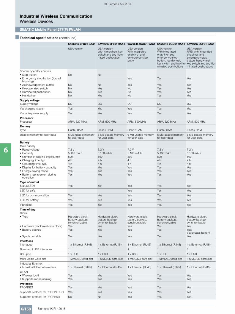
6/158 Siemens IK PI · 2015
6
■ Technical specifications (continued)
Industrial Wireless CommunicationWireless Devices
SIMATIC Mobile Panel 277(F) IWLAN
Special operator controls• Stop button No No• Emergency stop button (forced
blocking)Yes Yes Yes
• Acknowledgement button No No Yes Yes Yes• Key-operated switch No Yes No Yes Yes• Illuminated pushbutton No Yes No Yes Yes• Handwheel No Yes No Yes Yes
Supply voltageSupply voltage DC DC DC DC DC
Via charging station Yes Yes Yes Yes Yes
Via table power supply Yes Yes Yes Yes Yes
ProcessorProcessor ARM, 520 MHz ARM, 520 MHz ARM, 520 MHz ARM, 520 MHz ARM, 520 MHz
MemoryType Flash / RAM Flash / RAM Flash / RAM Flash / RAM Flash / RAM
Usable memory for user data 6 MB usable memory for user data
6 MB usable memory for user data
6 MB usable memory for user data
6 MB usable memory for user data
6 MB usable memory for user data
BatteryMain battery• Rated voltage 7.2 V 7.2 V 7.2 V 7.2 V 7.2 V• Capacity 5 100 mA·h 5 100 mA·h 5 100 mA·h 5 100 mA·h 5 100 mA·h• Number of loading cycles, min 500 500 500 500 500• Charging time, typ. 4 h 4 h 4 h 4 h 4 h• Operating time, typ. 4 h 4 h 4 h 4 h 4 h• Display for battery capacity Yes Yes Yes Yes Yes• Energy-saving mode Yes Yes Yes Yes Yes• Battery replacement during
operationYes Yes Yes Yes Yes
Type of outputStatus LEDs Yes Yes Yes Yes Yes
LED for safe Yes Yes Yes
LED for communication Yes Yes Yes Yes Yes
LED for battery Yes Yes Yes Yes Yes
Vibrations Yes Yes Yes Yes Yes
Time of dayClock• Type Hardware clock,
battery backup, synchronizable
Hardware clock, battery backup, synchronizable
Hardware clock, battery backup, synchronizable
Hardware clock, battery backup, synchronizable
Hardware clock, battery backup, synchronizable
• Hardware clock (real-time clock) Yes Yes Yes Yes Yes• Battery-backed Yes Yes Yes Yes Yes;
Via bypass battery• Synchronizable Yes Yes Yes Yes Yes
InterfacesInterfaces 1 x Ethernet (RJ45) 1 x Ethernet (RJ45) 1 x Ethernet (RJ45) 1 x Ethernet (RJ45) 1 x Ethernet (RJ45)
Number of USB interfaces 1 1 1 1 1
USB port 1 x USB 1 x USB 1 x USB 1 x USB 1 x USB
Multi Media Card slot 1 MMC/SD card slot 1 MMC/SD card slot 1 MMC/SD card slot 1 MMC/SD card slot 1 MMC/SD card slot
Industrial Ethernet• Industrial Ethernet interface 1 x Ethernet (RJ45) 1 x Ethernet (RJ45) 1 x Ethernet (RJ45) 1 x Ethernet (RJ45) 1 x Ethernet (RJ45)
WLAN• Wireless LAN Yes Yes Yes Yes Yes• Supports rapid roaming Yes Yes Yes Yes Yes
ProtocolsPROFINET Yes Yes Yes Yes Yes
Supports protocol for PROFINET IO Yes Yes Yes Yes Yes
Supports protocol for PROFIsafe No No Yes Yes Yes
6AV6645-0FD01-0AX1 6AV6645-0FE01-0AX1 6AV6645-0GB01-0AX1 6AV6645-0GC01-0AX1 6AV6645-0GF01-0AX1
USA version USA versionWith handwheel key switch and two illumi-nated pushbutton
USA versionWith integrated enabling- and emergency-stop button
USA versionWith integrated enabling- and emergency-stop button, handwheel, key switch and two illu-minated pushbuttons
USA versionRFID with integrated enabling- and emergency-stop button, handwheel, key switch and two illu-minated pushbuttons
Kap_06_IWC_en.book Seite 158 Dienstag, 7. Oktober 2014 1:47 13
© Siemens AG 2014

6/159Siemens IK PI · 2015
6
■ Technical specifications (continued)
Industrial Wireless CommunicationWireless Devices
SIMATIC Mobile Panel 277(F) IWLAN
EMCEmission of radio interference acc. to EN 55 011• Emission of radio interferences acc.
to EN 55 011 (limit class A)Yes; The product is designed for use in industrial environ-ments. When used in residential areas, the emission of radio inter-ference according to limit class B of EN 55011 must be ensured. For further information refer to the user documentation
Yes; The product is designed for use in industrial environ-ments. When used in residential areas, the emission of radio inter-ference according to limit class B of EN 55011 must be ensured. For further information refer to the user documentation
Yes; The product is designed for use in industrial environ-ments. When used in residential areas, the emission of radio inter-ference according to limit class B of EN 55011 must be ensured. For further information refer to the user documentation
Yes; The product is designed for use in industrial environ-ments. When used in residential areas, the emission of radio inter-ference according to limit class B of EN 55011 must be ensured. For further information refer to the user documentation
Yes; The product is designed for use in industrial environ-ments. When used in residential areas, the emission of radio inter-ference according to limit class B of EN 55011 must be ensured. For further information refer to the user documentation
Degree and class of protectionIP65 enclosure Yes Yes Yes Yes Yes
Standards, approvals, certificatesCertifications CE, cULus, C-TICK CE, cULus, C-TICK CE, cULus, C-TICK CE, cULus, C-TICK CE, cULus, C-TICK
CE mark Yes Yes Yes Yes Yes
cULus Yes Yes Yes Yes Yes
RCM (former C-TICK) Yes Yes Yes Yes Yes
TÜV safety certification Yes Yes Yes
Highest safety class achievable in safety mode• Performance level
according to EN ISO 13849-1:2008e e e
• SIL according to IEC 61508:2010 SIL 3 SIL 3 SIL 3
Ambient conditionsDrop height 1.2 m 1.2 m 1.2 m 1.2 m 1.2 m
Operating temperature• Operation 0 °C to +40 °C 0 °C to +40 °C 0 °C to +40 °C 0 °C to +40 °C 0 °C to +40 °C
Storage/transport temperature• Transport, storage -20 °C to +60 °C -20 °C to +60 °C -20 °C to +60 °C -20 °C to +60 °C -20 °C to +60 °C
Relative humidity• max. relative humidity 80 % 80 % 80 % 80 % 80 %
Operating systemsOperating system Windows CE Windows CE Windows CE Windows CE Windows CE
LanguagesOnline languages• Number of online/runtime
languages16 16 16 16 16
Functionality under WinCC (TIA Portal)Libraries Yes Yes Yes Yes Yes
Task planner Yes Yes Yes Yes Yes
Message system• Number of messages 4 000 4 000 4 000 4 000 4 000• Bit messages Yes Yes Yes Yes Yes• Analog messages Yes Yes Yes Yes Yes
Recipe administration• Number of recipes 300 300 300 300 300• Data records per recipe 500 500 500 500 500• Entries per data record 1 000 1 000 1 000 1 000 1 000• Recipe memory 64 KB integrated
Flash, expandable64 KB integrated Flash, expandable
64 KB integrated Flash, expandable
64 KB integrated Flash, expandable
64 KB integrated Flash, expandable
Variables• Number of variables per device 2 048 2 048 2 048 2 048 2 048• Limit values Yes Yes Yes Yes Yes• Multiplexing Yes Yes Yes Yes Yes
6AV6645-0FD01-0AX1 6AV6645-0FE01-0AX1 6AV6645-0GB01-0AX1 6AV6645-0GC01-0AX1 6AV6645-0GF01-0AX1
USA version USA versionWith handwheel key switch and two illumi-nated pushbutton
USA versionWith integrated enabling- and emergency-stop button
USA versionWith integrated enabling- and emergency-stop button, handwheel, key switch and two illu-minated pushbuttons
USA versionRFID with integrated enabling- and emergency-stop button, handwheel, key switch and two illu-minated pushbuttons
Kap_06_IWC_en.book Seite 159 Dienstag, 7. Oktober 2014 1:47 13
© Siemens AG 2014
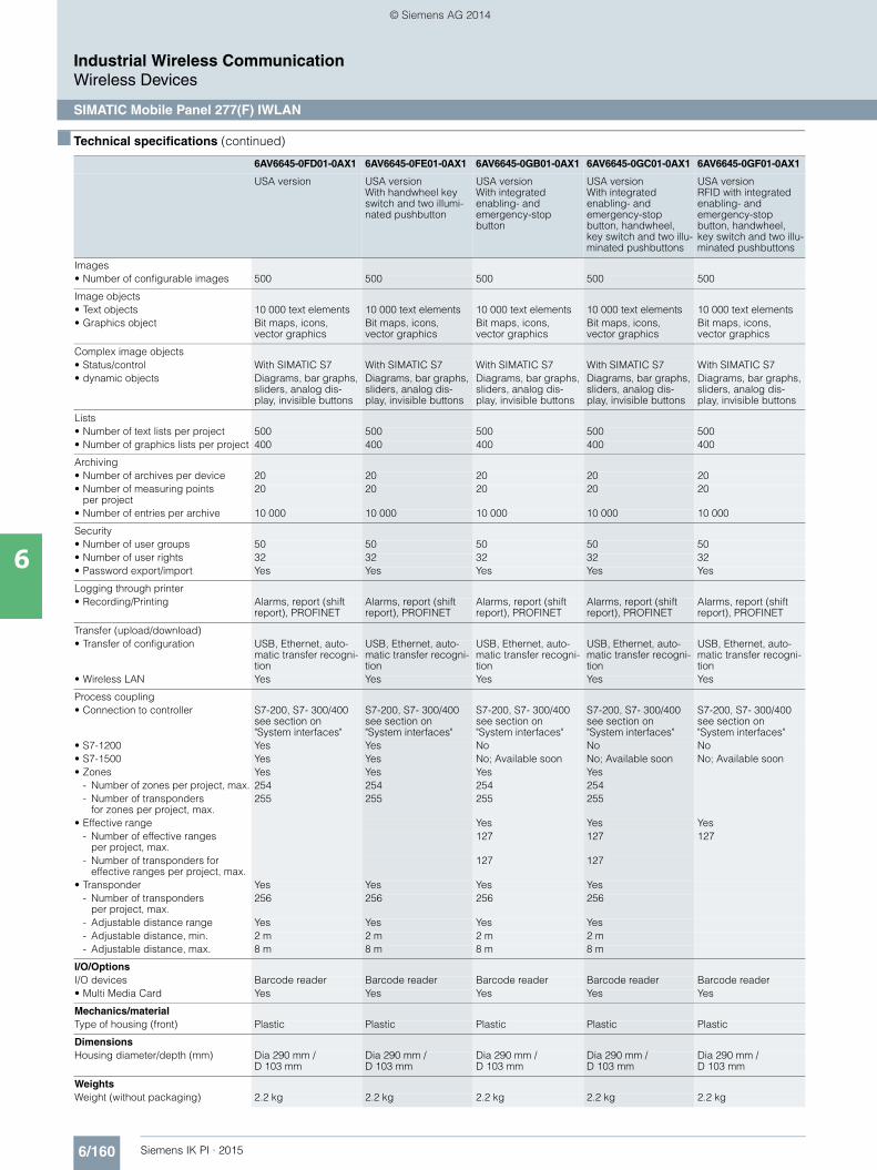
6/160 Siemens IK PI · 2015
6
■ Technical specifications (continued)
Industrial Wireless CommunicationWireless Devices
SIMATIC Mobile Panel 277(F) IWLAN
Images• Number of configurable images 500 500 500 500 500
Image objects• Text objects 10 000 text elements 10 000 text elements 10 000 text elements 10 000 text elements 10 000 text elements• Graphics object Bit maps, icons,
vector graphicsBit maps, icons, vector graphics
Bit maps, icons, vector graphics
Bit maps, icons, vector graphics
Bit maps, icons, vector graphics
Complex image objects• Status/control With SIMATIC S7 With SIMATIC S7 With SIMATIC S7 With SIMATIC S7 With SIMATIC S7• dynamic objects Diagrams, bar graphs,
sliders, analog dis-play, invisible buttons
Diagrams, bar graphs, sliders, analog dis-play, invisible buttons
Diagrams, bar graphs, sliders, analog dis-play, invisible buttons
Diagrams, bar graphs, sliders, analog dis-play, invisible buttons
Diagrams, bar graphs, sliders, analog dis-play, invisible buttons
Lists• Number of text lists per project 500 500 500 500 500• Number of graphics lists per project 400 400 400 400 400
Archiving• Number of archives per device 20 20 20 20 20• Number of measuring points
per project20 20 20 20 20
• Number of entries per archive 10 000 10 000 10 000 10 000 10 000
Security• Number of user groups 50 50 50 50 50• Number of user rights 32 32 32 32 32• Password export/import Yes Yes Yes Yes Yes
Logging through printer• Recording/Printing Alarms, report (shift
report), PROFINETAlarms, report (shift report), PROFINET
Alarms, report (shift report), PROFINET
Alarms, report (shift report), PROFINET
Alarms, report (shift report), PROFINET
Transfer (upload/download)• Transfer of configuration USB, Ethernet, auto-
matic transfer recogni-tion
USB, Ethernet, auto-matic transfer recogni-tion
USB, Ethernet, auto-matic transfer recogni-tion
USB, Ethernet, auto-matic transfer recogni-tion
USB, Ethernet, auto-matic transfer recogni-tion
• Wireless LAN Yes Yes Yes Yes Yes
Process coupling• Connection to controller S7-200, S7- 300/400
see section on "System interfaces"
S7-200, S7- 300/400 see section on "System interfaces"
S7-200, S7- 300/400 see section on "System interfaces"
S7-200, S7- 300/400 see section on "System interfaces"
S7-200, S7- 300/400 see section on "System interfaces"
• S7-1200 Yes Yes No No No• S7-1500 Yes Yes No; Available soon No; Available soon No; Available soon• Zones Yes Yes Yes Yes
- Number of zones per project, max. 254 254 254 254- Number of transponders
for zones per project, max.255 255 255 255
• Effective range Yes Yes Yes- Number of effective ranges
per project, max.127 127 127
- Number of transponders for effective ranges per project, max.
127 127
• Transponder Yes Yes Yes Yes- Number of transponders
per project, max.256 256 256 256
- Adjustable distance range Yes Yes Yes Yes- Adjustable distance, min. 2 m 2 m 2 m 2 m- Adjustable distance, max. 8 m 8 m 8 m 8 m
I/O/OptionsI/O devices Barcode reader Barcode reader Barcode reader Barcode reader Barcode reader• Multi Media Card Yes Yes Yes Yes Yes
Mechanics/materialType of housing (front) Plastic Plastic Plastic Plastic Plastic
DimensionsHousing diameter/depth (mm) Dia 290 mm /
D 103 mmDia 290 mm / D 103 mm
Dia 290 mm / D 103 mm
Dia 290 mm / D 103 mm
Dia 290 mm / D 103 mm
WeightsWeight (without packaging) 2.2 kg 2.2 kg 2.2 kg 2.2 kg 2.2 kg
6AV6645-0FD01-0AX1 6AV6645-0FE01-0AX1 6AV6645-0GB01-0AX1 6AV6645-0GC01-0AX1 6AV6645-0GF01-0AX1
USA version USA versionWith handwheel key switch and two illumi-nated pushbutton
USA versionWith integrated enabling- and emergency-stop button
USA versionWith integrated enabling- and emergency-stop button, handwheel, key switch and two illu-minated pushbuttons
USA versionRFID with integrated enabling- and emergency-stop button, handwheel, key switch and two illu-minated pushbuttons
Kap_06_IWC_en.book Seite 160 Dienstag, 7. Oktober 2014 1:47 13
© Siemens AG 2014

6/161Siemens IK PI · 2015
Industrial Wireless CommunicationWireless Devices
SIMATIC Mobile Panel 277(F) IWLAN
6
■ Ordering data Article No. Article No.
1) RoW version:"Rest of World" version: Version for worldwide sales except in the U.S.
Note:The Function Manuals "Fail-Safe Operation of the Mobile Panel 277F IWLAN V1" are available for downloading in English, German, and Japanese. http://support.automation.siemens.com/WW/view/en/31255853
■ More information
Additional information is available in the Internet under:http://www.siemens.com/simatic-mobile-panels
Note:Do you need a specific modification or addition to the products described here? Then take a look under "Customer-specific products". There, you will find information on ordering additional and standard industry products as well as possibilities for customer-specific modifications and adjustments.
SIMATIC Mobile Panel 277 IWLAN V2 (RoW version 1))• Communication via WLAN
(PROFINET)6AV6645-0DD01-0AX1
• Communication via WLAN (PROFINET) with integrated handwheel, key-operated switch and two illuminated pushbuttons
6AV6645-0DE01-0AX1
SIMATIC Mobile Panel 277F IWLAN V2 PROFIsafe (RoW version 1))• Communication via WLAN
(PROFINET) with acknowledgement button and emergency stop button
6AV6645-0EB01-0AX1
• Communication via WLAN (PROFINET) with acknowledgement button and emergency stop button with inte-grated handwheel, key-operated switch, and two illuminated push-buttons
6AV6645-0EC01-0AX1
• RFID tag version: Communication via WLAN (PROFINET) with acknowledgement button and emergency stop button with integrated handwheel, key-operated switch, and two illuminated pushbuttons
6AV6645-0EF01-0AX1
SIMATIC Mobile Panel 277 IWLAN V2 (USA version)• Communication via WLAN
(PROFINET)6AV6645-0FD01-0AX1
• Communication via WLAN (PROFINET) with integrated handwheel, key-operated switch and two illuminated pushbuttons
6AV6645-0FE01-0AX1
SIMATIC Mobile Panel 277F IWLAN V2 PROFIsafe (USA version)• with acknowledgement button and
emergency stop button6AV6645-0GB01-0AX1
• with acknowledgement button and emergency stop button with integrated handwheel, key-operated switch, and twoilluminated pushbuttons
6AV6645-0GC01-0AX1
• with acknowledgement button and emergency stop button with integrated handwheel, key-operated switch, and two illuminated pushbuttons (tag version)
6AV6645-0GF01-0AX1
Starter kit SIMATIC Mobile Panel 277(F) IWLAN (RoW version1))
for• Mobile Panel 277 IWLAN V2 6AV6651-5GA01-0AA1• Mobile Panel 277F IWLAN V2 6AV6651-5HA01-0AA1
Accessories See HMI accessories
Note: Please order the table-top power supply or charging station as well. Required for charging the bat-tery.
Documentation (to be ordered separately)
You can find the manuals for the Mobile Panels on the Internet at:
http://support.automation.sie-mens.com/WW/view/en/11599011/133300
Kap_06_IWC_en.book Seite 161 Dienstag, 7. Oktober 2014 1:47 13
© Siemens AG 2014
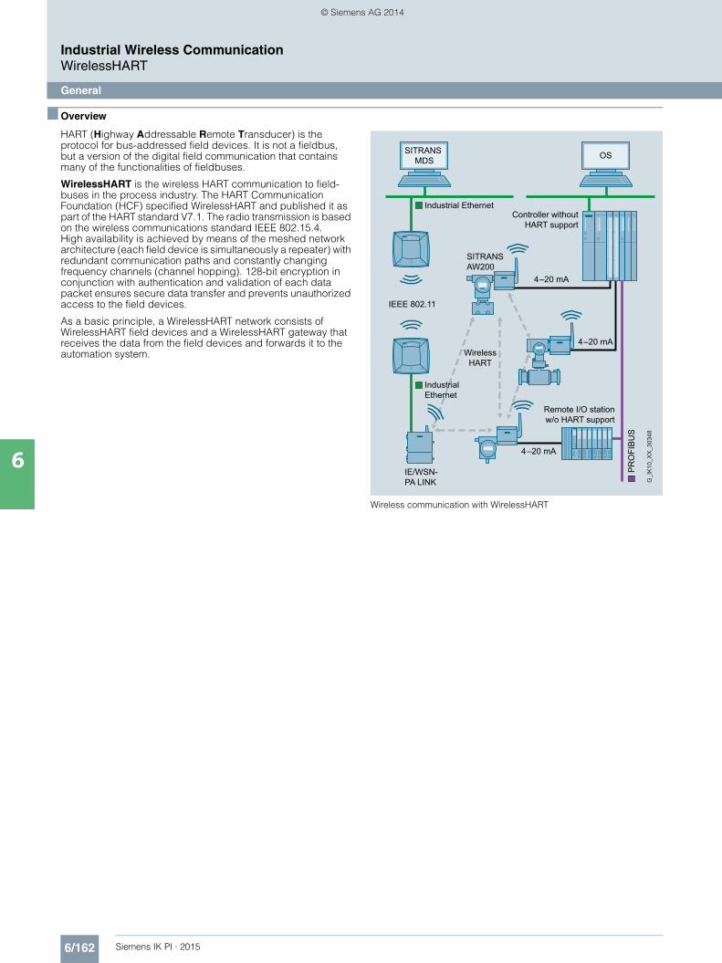
6/162 Siemens IK PI · 2015
Industrial Wireless CommunicationWirelessHART
General
6
■ Overview
HART (Highway Addressable Remote Transducer) is the protocol for bus-addressed field devices. It is not a fieldbus, but a version of the digital field communication that contains many of the functionalities of fieldbuses.
WirelessHART is the wireless HART communication to field-buses in the process industry. The HART Communication Foundation (HCF) specified WirelessHART and published it as part of the HART standard V7.1. The radio transmission is based on the wireless communications standard IEEE 802.15.4. High availability is achieved by means of the meshed network architecture (each field device is simultaneously a repeater) with redundant communication paths and constantly changing frequency channels (channel hopping). 128-bit encryption in conjunction with authentication and validation of each data packet ensures secure data transfer and prevents unauthorized access to the field devices.
As a basic principle, a WirelessHART network consists of WirelessHART field devices and a WirelessHART gateway that receives the data from the field devices and forwards it to the automation system.
Wireless communication with WirelessHART
Controller without HART support
Remote I/O station w/o HART support
SITRANS MDS OS
IE/WSN-PA LINK
SITRANS AW200
Industrial Ethernet
Industrial Ethernet
PR
OFI
BU
S
Wireless HART
IEEE 802.11
4–20 mA
4–20 mA
4–20 mA
G_I
K10
_XX
_303
48
Kap_06_IWC_en.book Seite 162 Dienstag, 7. Oktober 2014 1:47 13
© Siemens AG 2014

6/163Siemens IK PI · 2015
Industrial Wireless CommunicationWirelessHART
SITRANS P280 for gauge and absolute pressure
6
■ Overview
SITRANS P280 for flexible and cost-effective applications in pressure monitoring• Supports the WirelessHART standard (HART V 7.1)• Very high security level for wireless data transmission• Built-in local user interface (LUI) with 3-button operation• Optimum display and readability using graphics display
(104 x 80 pixels) with integrated background illumination• Stand-by (deep sleep phase) can be activated and deacti-
vated on the device with a push of a button• Battery power supply• Battery service live up to 5 years• Extend battery service life with HART modem interface which
can be shut off• Optimized power consumption through new design, and
increase in battery service life• Simple configuration thanks to SIMATIC PDM• Device meets IP65 degree of protection• Can be used for absolute and gauge pressure measurements
■ Benefits
The SITRANS P280 is a pressure transmitter that features Wireless HART as the standard communication interface.
Also available is a wired interface to connect a HART modem:• Flexible pressure measurements• Save costs on writing for difficult installation conditions.
Wireless technology offers cost advantages in cases where extensive wiring cots would normally apply.
• It enables additional hitherto unfeasible measuring points, particularly for monitoring purposes.
• Easy installation on moveable equipment parts• Enables cost-effective temporary measurements, for example
for process optimizations.• Optimum addition to wired communication and expansion of
solution options for system solutions in process automation
■ Application
The SITRANS P280 is a WirelessHART field device for measuring absolute and gauge pressure.
The measuring ranges for absolute and gauge pressure measurements are 0 to 1.6, 10, 50, 200 and 320 bar (0 to 23, 145, 725, 2900 and 4641 psi).
The sensor is integrated into the transmitter casing.
On the wireless communication side, the transmitter supports the WirelessHART standard. For initial commissioning in particular, a HART modem can be connected to the transmitter. You can alternatively opt for simple and easy local operation using the pushbuttons w/o any additional handset devices.
It can be used in all industries and applications in non-explosive areas.
■ Design
The SITRANS P280 has a robust aluminum enclosure and is suitable for outside use. It conforms with the IP65 safety class.
The operating temperature range is -40 to +80 °C (-40 to +176 °F). Power supply is provided through an integrated battery, which is available as an accessory. The device is only approved for operation with this battery.
The aerial features a rotatable joint which can be used for directional alignment. Wireless signals can thus be optimally received and transmitted.
A special highlight is the option for direct operation on the device. The operating strategy used in this case seamlessly integrates into the strategy of all new Siemens field devices.
Using the device's control buttons, it is easy to turn the HART modem interface of the device on and off. The device can be put to passive status and reactivated at any time. This helps to ex-tend the service life of the battery.
The SITRANS P280 transmitter features a ceramic measuring cell for gauge and absolute pressure measurements.
■ Function
The SITRANS P280 can integrate itself into a WirelessHART network. It can be parameterized and operated through this network. Measured process values are transported via the net-work to the SIEMENS IE/WSN-PA link.
Field device data received by the IE/WSN-PA LINK is transmitted to the connected systems, for example the process control sys-tem SIMATIC PCS 7. For an introduction to the mode of operation of WirelessHART, please see the FI 01 catalogue, section 9 or http://www.siemens.com/wirelesshart.
Detailed information on IE/WSN-PA can be found in the FI 01 catalogue, section 8 or http://www.siemens.com/wirelesshart.
Kap_06_IWC_en.book Seite 163 Dienstag, 7. Oktober 2014 1:47 13
© Siemens AG 2014
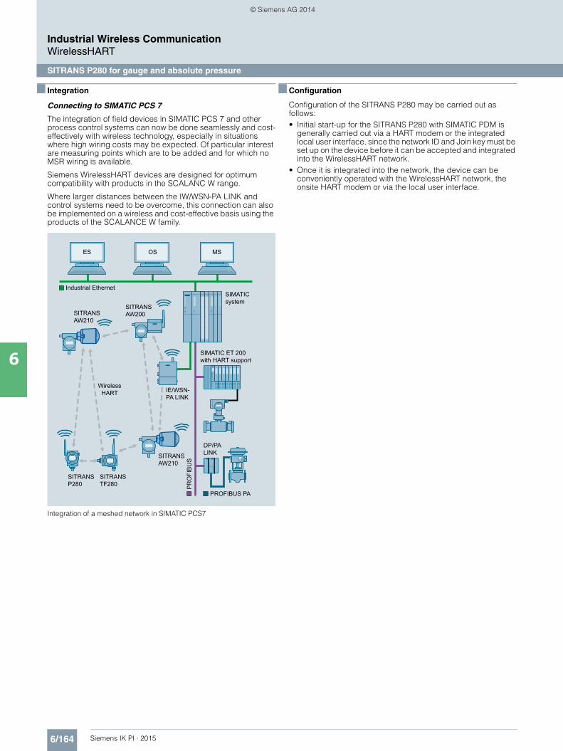
6/164 Siemens IK PI · 2015
Industrial Wireless CommunicationWirelessHART
SITRANS P280 for gauge and absolute pressure
6
■ Integration
Connecting to SIMATIC PCS 7
The integration of field devices in SIMATIC PCS 7 and other process control systems can now be done seamlessly and cost-effectively with wireless technology, especially in situations where high wiring costs may be expected. Of particular interest are measuring points which are to be added and for which no MSR wiring is available.
Siemens WirelessHART devices are designed for optimum compatibility with products in the SCALANC W range.
Where larger distances between the IW/WSN-PA LINK and control systems need to be overcome, this connection can also be implemented on a wireless and cost-effective basis using the products of the SCALANCE W family.
Integration of a meshed network in SIMATIC PCS7
■ Configuration
Configuration of the SITRANS P280 may be carried out as follows:• Initial start-up for the SITRANS P280 with SIMATIC PDM is
generally carried out via a HART modem or the integrated local user interface, since the network ID and Join key must be set up on the device before it can be accepted and integrated into the WirelessHART network.
• Once it is integrated into the network, the device can be conveniently operated with the WirelessHART network, the onsite HART modem or via the local user interface.
SIMATIC system
SIMATIC ET 200 with HART support
ES OS MS
IE/WSN-PA LINK
SITRANSAW210
SITRANSAW200
SITRANS AW210
SITRANS TF280
SITRANS P280
DP/PA LINK
Industrial Ethernet
PR
OFI
BU
S
Wireless HART
PROFIBUS PA
Kap_06_IWC_en.book Seite 164 Dienstag, 7. Oktober 2014 1:47 13
© Siemens AG 2014

6/165Siemens IK PI · 2015
Industrial Wireless CommunicationWirelessHART
SITRANS P280 for gauge and absolute pressure
6
■ Technical specifications
SITRANS P280 WirelessHART Pressure Transmitter
Mode of operation
Measuring principle piezo-resistive
Measured variable Gauge and absolute pressure
Gauge pressure input
Measuring range Overload limit/Burst pressure
0 ... 1.6 bar (0 ... 23 psi) 4 bar (58 psi)
0 ... 10 bar (0 ... 145 psi) 20 bar (290 psi)
0 ... 50 bar (0 ... 725 psi) 100 bar (1 450 psi)
0 ... 200 bar (0 ... 2900 psi) 400 bar (5 801 psi)
0 ... 320 bar (0 ... 4641 psi) 640 bar (9 282 psi)
Units mbar, bar, m4H2O, i4H2O, atm, Torr, gcm², kgcm², Pa, kPa, MPa, psi, mmHG, mmH2O, ftH2O, inHG, inH2O
Absolute pressure input
Measuring range Overload limit/Burst pressure
0 ... 1.6 bar a (0 ... 23 psi a) 4 bar a (58 psi a)
0 ... 10 bar a (0 ... 145 psi a) 20 bar a (290 psi a)
0 ... 50 bar a (0 ... 725 psi a) 100 bar a (1450 psi a)
0 ... 200 bar a (0 ... 2900 psi a) 400 bar a (5801 psi a)
0 ... 320 bar a (0 ... 4641 psi a) 640 bar a (9282 psi a)
Units mbar, bar, m4H2O, i4H2O, atm, Torr, gcm², kgcm², Pa, kPa, MPa, psi, mmHG, mmH2O, ftH2O, inHG, inH2O
Output
Output signal 2.4 GHz Wireless signal with TSMP (Time Synchronized Mesh Protocol)
Measuring accuracy According to IEC 60770-1
Error in measurement atlimit setting including hysteresis and reproducibility
typically 0.17 % of span, max. 0.25 % of sensor span
Long-term stability max. ± 0.25 % of sensor/year span
Influence of ambient temperature max. ± 0.2 %/10 K of sensor span
Rated conditions
Ambient conditions• Ambient temperature -40 ... +80 °C (-40 ... +176 °F)
(in ambient temperatures below -20 °C (-4 °F) and above +70 °C (158 °F), readability of the display is limited.)
• Storage temperature -40 ... +85 °C (-40 ... +185 °F)• Relative humidity < 95 %
Climatic class 4K4H in accordance with EN 60721-3-4(stationary use at loca-tions not protected against weather)
Degree of protection IP65/NEMA 4
Permissible medium temperature -40 ... 85 °C (-40 ... +185 °F)
Design
Enclosure material low-copper die-cast aluminum, GD-AISi12 (Fe)
Shock resistance in accordance with DIN EN 60068-2-29 / 03.95
Resistance to vibration in accordance with EN 60068-2-6/ 12.07
Weight• without battery 1.5 kg (3.31 lb)• With battery 1.6 kg (3.53 lb)
Dimensions (W x H x D) See Dimensional drawing
Process connection • G½B male thread to EN 837-1• ½-14 NPT
Sensor break Is recognized
Displays and controls
Display (with illumination)• Size of display 104 x 80 pixels• Number of digits adjustable• Number of spaces after comma adjustable
Setting options • on site with 3 buttons• with SIMATIC PDM
or HART Communicator
Auxiliary power
Battery 3.6 V DC
Communication
Radio WirelessHART V7.1 conforming
Transmission frequency band 2.4 GHz (ISM-Band)
Transmission range under reference conditions
Up to 250 m (line of sight) in outside areas
Up to 50 m (greatly dependent on obstacles) in inside areas
Communication interfaces • HART communication with HART modem
• WirelessHART
Certificates and approvals
Wireless communication approvals R&TTE, FCC
General product safety CSAUS/C, CE, UL
Classification according to pressure equipment directive (PED 97/23/EC)
Gases: Fluid group 1
Liquids: Fluid group 1;
meets requirements as per Section 3, Subsection 3 (good engineering practice)
SITRANS P280 WirelessHART Pressure Transmitter
Kap_06_IWC_en.book Seite 165 Dienstag, 7. Oktober 2014 1:47 13
© Siemens AG 2014
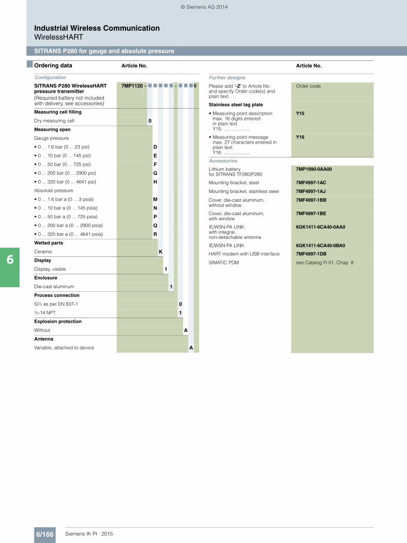
6/166 Siemens IK PI · 2015
Industrial Wireless CommunicationWirelessHART
SITRANS P280 for gauge and absolute pressure
6
■ Ordering data Article No. Article No.
Configuration
SITRANS P280 WirelessHART pressure transmitter
7MP1120 - 7 7 7 7 7 - 7 7 7 0
(Required battery not included with delivery, see accessories)
Measuring cell filling
Dry measuring cell 0
Measuring span
Gauge pressure
• 0 ... 1.6 bar (0 ... 23 psi) D
• 0 ... 10 bar (0 ... 145 psi) E
• 0 ... 50 bar (0 ... 725 psi) F
• 0 ... 200 bar (0 ... 2900 psi) G
• 0 ... 320 bar (0 ... 4641 psi) H
Absolute pressure
• 0 ... 1.6 bar a (0 ... 3 psia) M
• 0 ... 10 bar a (0 ... 145 psia) N
• 0 ... 50 bar a (0 ... 725 psia) P
• 0 ... 200 bar a (0 ... 2900 psia) Q
• 0 ... 320 bar a (0 ... 4641 psia) R
Wetted parts
Ceramic K
Display
Display, visible 1
Enclosure
Die-cast aluminum 1
Process connection
G½ as per EN 837-1 0
½-14 NPT 1
Explosion protection
Without A
Antenna
Variable, attached to device A
Further designs
Please add "-Z" to Article No. and specify Order code(s) and plain text.
Order code
Stainless steel tag plate
• Measuring point descriptionmax. 16 digits enteredin plain text Y15: ....................
Y15
• Measuring point messagemax. 27 characters entered in plain text: Y16: ....................
Y16
Accessories
Lithium battery for SITRANS TF280/P280
7MP1990-0AA00
Mounting bracket, steel 7MF4997-1AC
Mounting bracket, stainless steel 7MF4997-1AJ
Cover, die-cast aluminum, without window
7MF4997-1BB
Cover, die-cast aluminum, with window
7MF4997-1BE
IE/WSN-PA LINKwith integral, non-detachable antenna
6GK1411-6CA40-0AA0
IE/WSN-PA LINK 6GK1411-6CA40-0BA0
HART modem with USB interface 7MF4997-1DB
SIMATIC PDM see Catalog FI 01, Chap. 8
Kap_06_IWC_en.book Seite 166 Dienstag, 7. Oktober 2014 1:47 13
© Siemens AG 2014

6/167Siemens IK PI · 2015
Industrial Wireless CommunicationWirelessHART
SITRANS TF280, WirelessHART
6
■ Overview
SITRANS TF280 for flexible and cost-effective temperature measurements• Supports the WirelessHART standard (HART V 7.1)• Very high security level for wireless data transmission• Built-in local user interface (LUI) with 3-button operation• Optimum display and readability using graphics display
(104 x 80 pixels) with integrated background lighting• Stand-by (deep sleep phase) on device can be turned on and
off with a push of a button• Battery power supply• Battery service live up to 5 years• Extend battery service life with HART modem interface which
can be shut off• Optimized power consumption through new design, and
increase in battery service life• Simple configuration thanks to SIMATIC PDM• Housing meets IP65 degree of protection• Supports all Pt100 sensors as per IEC 751/DIN EN 60751
■ Benefits
The SITRANS TF280 is a temperature transmitter that features Wireless HART as the standard communication interface.
Also available is a wired interface to connect a HART modem:• Flexible temperature measurement• Save costs on writing for difficult installation conditions.
Wireless technology offers cost advantages in cases where extensive wiring cots would normally apply.
• It enables additional hitherto unfeasible measuring points, particularly for monitoring purposes
• Easy installation also on moveable equipment parts• Enables cost-effective temporary measurements, for example
for process optimizations.• Optimum addition to wired communication and expansion of
solution options for system solutions in process automation
■ Application
The SITRANS TF280 is a WirelessHART field device for measuring temperature with a Pt100 sensor.
This sensor can be installed directly on the field device, or con-nected at an offset with a cable connection. On the wireless communication side, the transmitter supports the WirelessHART standard. A HART modem can be connected to the transmitter particularly for initial parameterization.
It can be used in all industries and applications in non-explosive areas.
■ Design
The SITRANS TF280 has a robust aluminum enclosure and is suitable for outside use. It conforms with the IP65 safety class.
The operating temperature range is -40 to +80 °C (-40 to +176 °F). Power supply is provided through an integrated battery, which is available as an accessory. The device is only approved for operation with this battery.
The aerial features a rotatable joint which can be used for directional alignment. Wireless signals can thus be optimally received and transmitted.
A special highlight is the option for direct operation on the device. The operating strategy used in this case seamlessly integrates into the strategy of all new SIEMENS field devices.
Using the device's control buttons, it is easy to turn the HART modem interface of the device on and off. The device can be put to passive status and reactivated at any time. This helps to extend the service life of the battery.
The SITRANS TF280 transmitter features a cable gland or a Pt100 sensor including protective piping.
■ Function
The SITRANS TF280 can integrate itself into a WirelessHART network. It can be parameterized and operated through this network. Measured process values are transported via the net-work to the SIEMENS IE/WSN-PA LINK.
Field device data received by the IE/WSN-PA LINK is transmitted to the connected systems, for example the process control sys-tem SIMATIC PCS 7. For an introduction to the mode of operation of WirelessHART, please see the FI 01 catalog chapter 8 or at http://www.siemens.com/wirelesshart.
Detailed information on IE/WSN-PA LINK can be foundin the FI 01 catalog chapter 8 or at http://www.siemens.com/wirelesshart.
Kap_06_IWC_en.book Seite 167 Dienstag, 7. Oktober 2014 1:47 13
© Siemens AG 2014
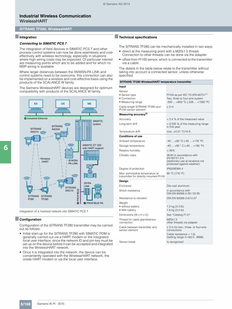
6/168 Siemens IK PI · 2015
Industrial Wireless CommunicationWirelessHART
SITRANS TF280, WirelessHART
6
■ Integration
Connecting to SIMATIC PCS 7
The integration of field devices in SIMATIC PCS 7 and other process control systems can now be done seamlessly and cost-effectively with wireless technology, especially in situations where high wiring costs may be expected. Of particular interest are measuring points which are to be added and for which no MSR wiring is available.
Where larger distances between the IW/WSN-PA LINK and control systems need to be overcome, this connection can also be implemented on a wireless and cost-effective basis using the products of the SCALANCE W family.
The Siemens WirelessHART devices are designed for optimum compatibility with products of the SCALANCE W family.
Integration of a meshed network into SIMATIC PCS 7
■ Configuration
Configuration of the SITRANS TF280 transmitter may be carried out as follows:• Initial start-up for the SITRANS TF280 with SIMATIC PDM is
generally carried out via a HART modem or the integrated local user interface, since the network ID and join key must be set up on the device before it can be accepted and integrated into the WirelessHART network.
• Once it is integrated into the network, the device can be conveniently operated with the WirelessHART network, the onsite HART modem or via the local user interface.
■ Technical specifications
The SITRANS TF280 can be mechanically installed in two ways:• direct at the measuring point with a M20x1.5 thread
Connection to other threads can be done via the adapter.• offset from Pt100 sensor, which is connected to the transmitter
via a cable
The details in the table below relate to the transmitter without taking into account a connected sensor, unless otherwise specified.
SIMATIC system
SIMATIC ET 200 with HART support
ES OS MS
IE/WSN-PA LINK
SITRANSAW210
SITRANSAW200
SITRANS AW210
SITRANS TF280
SITRANS P280
DP/PA LINK
Industrial Ethernet
PR
OFI
BU
S
Wireless HART
PROFIBUS PA
SITRANS TF280 WirelessHART temperature transmitter
Input
Sensor• Sensor type Pt100 as per IEC 751/EN 607511)
• Connection Two, three or four-wire system• Measuring range -200 ... +850 °C (-328 ... +1560 °F)
Cable length SITRANS TF280 and Pt100 sensor element
3 m
Measuring accuracy2)
Accuracy < 0.4 % of the measured value
Long-term drift < 0.035 % of the measuring range in first year
Temperature drift max. ±0.01 °C/10 K
Conditions of use
Ambient temperature -40 ... +80 °C (-40 ... +176 °F)
Storage temperature -40 ... +85 ° C (-40 ... +185 °F)
Relative humidity < 95%
Climatic class 4K4H in accordance with EN 60721-3-4(stationary use at locations not protected against weather)
Degree of protection IP65/NEMA 4
Max. permissible temperature at transmitter for directly mounted Pt100
80 °C (176 °F)
Design
Enclosure Die-cast aluminum
Shock resistance in accordance with DIN EN 60068-2-29 / 03.95
Resistance to vibration DIN EN 60068-2-6/12.07
Weight• without battery 1.5 kg (3.3 lb)• With battery 1.6 kg (3.5 lb)
Dimensions (W x H x D) See “Catalog FI 01“
Thread for cable gland/sensor connection
M20x1.5other threads via adapter
Cable between transmitter and sensor element
3 m for two-, three- or four-wire connections
Cable resistance < 1 (setting range in m 0...9999)
Sensor break Is recognized
Kap_06_IWC_en.book Seite 168 Dienstag, 7. Oktober 2014 1:47 13
© Siemens AG 2014

6/169Siemens IK PI · 2015
■ Technical specifications (continued)
Industrial Wireless CommunicationWirelessHART
SITRANS TF280, WirelessHART
61) Preassembled Pt100: Class A (maximum MES: 0.15 + 0.002*|t| °C)2) Error calculation:
• Probable overall error = Ö(MES2 + AET2 + LTD2 + ATE2)• Maximum overall error = MES + AET + LTD + ATE• |t|: Absolute total of the measured temperature• MES: Measuring error of the sensor• AET: Measuring error of the transmitter (A/D conversion)• LTD: Long-term drift• ATE: Drift via ambient temperature
Displays and controls
Display (with illumination)• Size of display 104 x 80 pixels• Number of digits adjustable• Number of spaces after comma adjustable
Setting options • on site with 3 buttons• with SIMATIC PDM
or HART Communicator
Auxiliary power
Battery 3.6 V DC
Communication
Wireless standard WirelessHART V7.1 conforming
Transmission frequency band 2.4 GHz (ISM-Band)
Range under reference conditions) Up to 250 m (line of sight) in outside areas
Up to 50 m (greatly dependent on obstacles) in inside areas
Communication interfaces • HART communication with HART modem
• WirelessHART
Certificates and approvals
Wireless communication approvals R&TTE, FCC
Pressure equipment directive This device does not fall under the pressure equipment directive.
SITRANS TF280 WirelessHART temperature transmitter
■ Ordering data Article No.
1) Please order sensor separately.
Configuration
SITRANS TF280 WirelessHART Temperature transmitter
7MP1110 - 0 A 7 7 7 - 0 7 7 0
(Required battery not included with delivery, see accessories)
Connections/cable entry
Cable gland M20x1.5 1) C
Sensor pipe with Pt100, G½" male thread, pre-mounted and connected
D
Display
Digital display, visible 1
Enclosure
Die-cast aluminum 1
Explosion protection
Not included A
Antenna
Variable, attached to device A
Further designs
Please add "-Z" to Article No. and specify Order code(s) and plain text.
Order code
• Measuring point number (TAG No.)max. 16 digits enteredin plain text Y15: ....................
Y15
• Measuring point messagemax. 27 characters entered in plain text: Y16: ....................
Y16
Accessories
Lithium battery for SITRANS TF280/P280
7MP1990-0AA00
Mounting bracket, steel 7MF4997-1AC
Mounting bracket, stainless steel 7MF4997-1AJ
Cover, die-cast aluminum, without window
7MF4997-1BB
Cover, die-cast aluminum, with window
7MF4997-1BE
Thread adapter M20x1.5 (male thread) on ½-14 NP (female thread)
7MP1990-0BA00
Thread adapter M20x1.5 (male thread) on G½B(female thread)
7MP1990-0BB00
IE/WSN-PA LINKwith integral, non-detachable antenna
6GK1411-6CA40-0AA0
IE/WSN-PA LINKN connector for connection of external antennas
6GK1411-6CA40-0BA0
HART modem with USB interface 7MF4997-1DB
Kap_06_IWC_en.book Seite 169 Dienstag, 7. Oktober 2014 1:47 13
© Siemens AG 2014
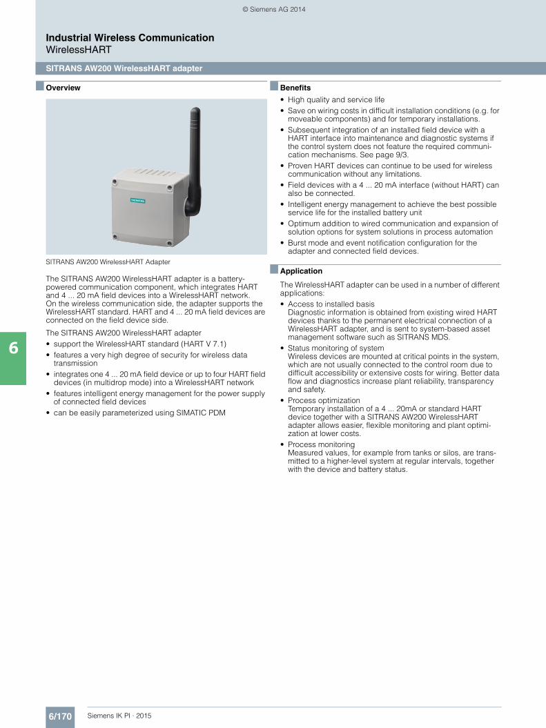
6/170 Siemens IK PI · 2015
Industrial Wireless CommunicationWirelessHART
SITRANS AW200 WirelessHART adapter
6
■ Overview
SITRANS AW200 WirelessHART Adapter
The SITRANS AW200 WirelessHART adapter is a battery-powered communication component, which integrates HART and 4 ... 20 mA field devices into a WirelessHART network. On the wireless communication side, the adapter supports the WirelessHART standard. HART and 4 ... 20 mA field devices are connected on the field device side.
The SITRANS AW200 WirelessHART adapter• support the WirelessHART standard (HART V 7.1)• features a very high degree of security for wireless data
transmission• integrates one 4 ... 20 mA field device or up to four HART field
devices (in multidrop mode) into a WirelessHART network• features intelligent energy management for the power supply
of connected field devices• can be easily parameterized using SIMATIC PDM
■ Benefits
• High quality and service life• Save on wiring costs in difficult installation conditions (e.g. for
moveable components) and for temporary installations.• Subsequent integration of an installed field device with a
HART interface into maintenance and diagnostic systems if the control system does not feature the required communi-cation mechanisms. See page 9/3.
• Proven HART devices can continue to be used for wireless communication without any limitations.
• Field devices with a 4 ... 20 mA interface (without HART) can also be connected.
• Intelligent energy management to achieve the best possible service life for the installed battery unit
• Optimum addition to wired communication and expansion of solution options for system solutions in process automation
• Burst mode and event notification configuration for the adapter and connected field devices.
■ Application
The WirelessHART adapter can be used in a number of different applications:• Access to installed basis
Diagnostic information is obtained from existing wired HART devices thanks to the permanent electrical connection of a WirelessHART adapter, and is sent to system-based asset management software such as SITRANS MDS.
• Status monitoring of systemWireless devices are mounted at critical points in the system, which are not usually connected to the control room due to difficult accessibility or extensive costs for wiring. Better data flow and diagnostics increase plant reliability, transparency and safety.
• Process optimizationTemporary installation of a 4 ... 20mA or standard HART device together with a SITRANS AW200 WirelessHART adapter allows easier, flexible monitoring and plant optimi-zation at lower costs.
• Process monitoringMeasured values, for example from tanks or silos, are trans-mitted to a higher-level system at regular intervals, together with the device and battery status.
Kap_06_IWC_en.book Seite 170 Dienstag, 7. Oktober 2014 1:47 13
© Siemens AG 2014
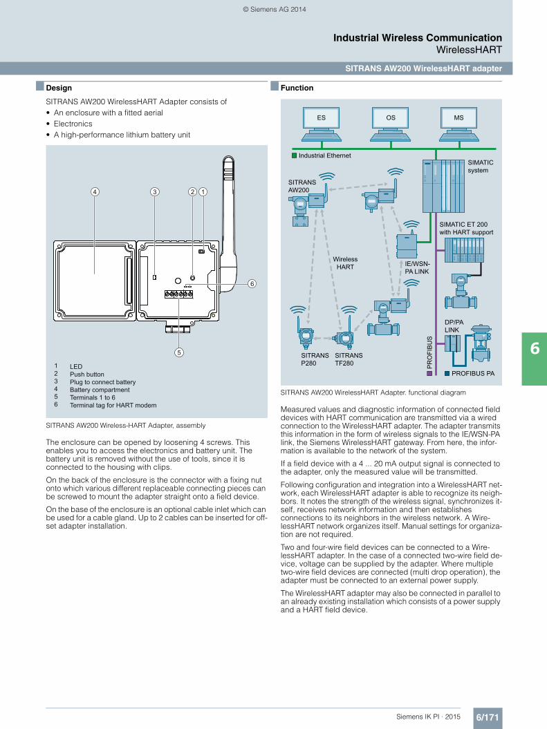
6/171Siemens IK PI · 2015
Industrial Wireless CommunicationWirelessHART
SITRANS AW200 WirelessHART adapter
6
■ Design
SITRANS AW200 WirelessHART Adapter consists of• An enclosure with a fitted aerial• Electronics• A high-performance lithium battery unit
SITRANS AW200 Wireless-HART Adapter, assembly
The enclosure can be opened by loosening 4 screws. This enables you to access the electronics and battery unit. The battery unit is removed without the use of tools, since it is connected to the housing with clips.
On the back of the enclosure is the connector with a fixing nut onto which various different replaceable connecting pieces can be screwed to mount the adapter straight onto a field device.
On the base of the enclosure is an optional cable inlet which can be used for a cable gland. Up to 2 cables can be inserted for off-set adapter installation.
■ Function
SITRANS AW200 WirelessHART Adapter. functional diagram
Measured values and diagnostic information of connected field devices with HART communication are transmitted via a wired connection to the WirelessHART adapter. The adapter transmits this information in the form of wireless signals to the IE/WSN-PA link, the Siemens WirelessHART gateway. From here, the infor-mation is available to the network of the system.
If a field device with a 4 ... 20 mA output signal is connected to the adapter, only the measured value will be transmitted.
Following configuration and integration into a WirelessHART net-work, each WirelessHART adapter is able to recognize its neigh-bors. It notes the strength of the wireless signal, synchronizes it-self, receives network information and then establishes connections to its neighbors in the wireless network. A Wire-lessHART network organizes itself. Manual settings for organiza-tion are not required.
Two and four-wire field devices can be connected to a Wire-lessHART adapter. In the case of a connected two-wire field de-vice, voltage can be supplied by the adapter. Where multiple two-wire field devices are connected (multi drop operation), the adapter must be connected to an external power supply.
The WirelessHART adapter may also be connected in parallel to an already existing installation which consists of a power supply and a HART field device.
1234
6
5
LEDPush buttonPlug to connect batteryBattery compartmentTerminals 1 to 6Terminal tag for HART modem
123456
SIMATIC system
SIMATIC ET 200 with HART support
ES OS MS
IE/WSN-PA LINK
SITRANS AW200
SITRANS TF280
SITRANS P280
DP/PA LINK
Industrial Ethernet
PR
OFI
BU
S
Wireless HART
PROFIBUS PA
Kap_06_IWC_en.book Seite 171 Dienstag, 7. Oktober 2014 1:47 13
© Siemens AG 2014

6/172 Siemens IK PI · 2015
■ Function (continued)
Industrial Wireless CommunicationWirelessHART
SITRANS AW200 WirelessHART adapter
6
Terminal block with 6 screw connection clamps
Parameterization
SITRANS AW200 configured via HART. Configuration can be carried out using a handheld communicator or, more conve-niently, with a HART modem and the SIMATIC PDM configuration software.
Initial startup of the adapter is usually carried out via SIMATIC PDM and a HART modem or a handheld communica-tor. During initial startup, the network ID and join key are set in the adapter. These parameters are used to integrate the adapter into an existing WirelessHART network.
Following integration into the network, the adapter and HART devices connected can be conveniently operated via the WirelessHART network or with the local HART modem.
Siemens HART field devices for the adapter
HART and 4…20mA field devices can be connected to the SITRANS AW200 WirelessHART adapter. Depending on the electrical data of the field devices, they can receive their power supply from the WirelessHART adapter or will require an external power supply. See http://www.siemens.com/automation/service&support for FAQ with the latest information on connectivity for Siemens field devices.
Note:
Siemens has only approved the Siemens HART field devices listed there for the adapter, and will only provide technical sup-port for these devices.
Based on HART specifications, it is generally possible to con-nect devices that are not listed, however with the following limi-tations:• All warranties and liability will be excluded• No technical support
Interface Connection Function
1 Power supply for the field device
2 HART/4 ... 20 mA
3 External supply/Dimensions
4 High-resistance HART connection
5, 7 High-resistance HART connection
6, 8 Mass, high-resistance connection
■ Technical specifications
Input
Input Point-to-Point connection to a HART field device or
Point-to-Point connection to a 4 ... 20 mA field device or
up to four HART field devices with external power supply which are inte-grated using the multidrop method
Communication HART communication using multidrop method, 4 ... 20 mA power signal with Point-to-Point connection
Protocol HART V7 (compatible with previous HART versions)
Transfer rate 1200 bits/s using HART multidrop method
Output
Communication WirelessHART V7
Transfer rate Nominal 250 kBits/s
Transmission frequency band 2.4 GHZ (ISM band)
Range (under reference conditions) Outside areas up to 250 m, within buildings up to 50 m
RF signal strength Can be configured: 0 dBm and 10 dBm
Output signals• WirelessHART Adapter Measured voltage and up to three
other variables may be selected from the following: adapter temperature, battery voltage, energy consumed, expected battery service life
• 4 ... 20 mA field device Scaled or linearized process values• HART field device up to four process variables, can be
configured via PDM or gateway
Measuring accuracy (as per reference conditions IEC 61298-2)
Max. measuring error (4 ... 20 mA circuit)
0.125 % re: measuring range
Effect of ambient temperature (4 ... 20 mA circuit)
5 µA/0°K
Rated conditions
Location Outside/Inside
Ambient conditions• Ambient temperature -40 ... +80 °C (-40 ... +176 °F)
The capacity of the battery decreases rapidly if ambient temperature falls flow -30 °C.
• Storage temperature -40 ... +85 °C (-40 ... +185 °F) without batteries
< 21 °C with batteries• Relative humidity Max 90 % at 25 °C (non-condensat-
ing)• Resistance to vibration 20 f 2000 Hz: 0.01 g²/Hz as per
IEC 68-2-64• Shock resistance 15 g, 11 ms as per IEC 68-2-27Electromagnetic compatibility As per EN 61326, EN 301 489-1/17
and NAMUR NE 21
Kap_06_IWC_en.book Seite 172 Dienstag, 7. Oktober 2014 1:47 13
© Siemens AG 2014

6/173Siemens IK PI · 2015
■ Technical specifications (continued)
Industrial Wireless CommunicationWirelessHART
SITRANS AW200 WirelessHART adapter
6
Design
Weight 0.5 kg without battery, 0.75 kg with battery
Enclosure• Material Polyester (PBT FR)• Cable entry 2x M20x1.5
Degree of protection IP65, IP66; NEMA 4
Aerial Omnidirectional dipolar aerial, vertical rotation
Mounting adapter M20x1.5 on M20x1.5, M20x1.5 on G½, M20x1.5 on ½ - 14 NPT, M20x1.5 on ¾ - 14 NPT
Auxiliary power
Battery Lithium thionylchlorid high-perfor-mance battery unit
Power supply 5 V DC ... 7.2 V DC
Capacity 19 AH at 20 °C
Service life 5 ... 7 years, depending on update rate, connected field device and ambient conditions
Field device voltage supply (not in multidrop mode)• No-load voltage 8 ... 23 V DC• Current 4 … 20mA (in accordance with
NAMUR Recommendation NE 43)• Fault current (not with multidrop) I 3.6 mA or I 21 mA• Protection Short-circuit proof,
activated at voltages > 25 mA
Voltage supply for one or more field devices (in multidrop mode)• Power < 30 V direct current• Current < 25 mA
Certificates and approvals
Wireless communication approvals ETSI (R&TTE)
FCC Part 15.247 for wireless applications in the 2.4 GHz transmission frequency band
EN 300 328
■ Ordering data Article No.
1) Additional approvals in process
Note:
Circuit diagrams and dimensional drawings can be found in Catalog FI 01.
Configuration
SITRANS AW200 adapter for Wireless HART Communication
7MP3112 - 7 7 7 7 0 - 0 A A 0
WirelessHART adapter AW200 with 4 ... 20 mA- or HART interface
Without battery 1
Power supply
Battery powered A
Certificates and approvals1)
Without A
Enclosure
Polyester 0
Accessories
Lithium batteryfor SITRANS AW200
7MP3990-0AA00
Thread adapter for direct mounting of the adapter to a field device
• M20 thread adapter 7MP3990-0BA00
• Thread adapter G½ 7MP3990-0BB00
• Thread adapter ½" - 14 NPT 7MP3990-0BC00
• Thread adapter ¾" - 14 NPT 7MP3990-0BD00
Mounting bracket for attaching to wall/pipe, material: stainless steel SS304, including cable gland
7MP3990-0CA00
Kap_06_IWC_en.book Seite 173 Dienstag, 7. Oktober 2014 1:47 13
© Siemens AG 2014

6/174 Siemens IK PI · 2015
Industrial Wireless CommunicationWirelessHART
SITRANS AW210 WirelessHART adapter
6
■ Overview
SITRANS AW210 WirelessHART adapter
The WirelessHART adapter SITRANS AW210 is a communi-cation component which can integrate a wide range of field devices into a WirelessHART network. On the wireless commu-nication side, the adapter supports the WirelessHART standard. HART and 4 to 20 mA field devices are connected on the field device side.
The WirelessHART adapter SITRANS AW210• Supports the WirelessHART standard (HART V 7.1)• Features an extremely high degree of security for wireless
data transmission.• Integrates a 4 to 20 mA field device into a WirelessHART
network• Integrates up to eight HART field devices (in multidrop mode)
into a WirelessHART network• Can be powered with the 4 to 20 mA loop or an external power
supply• Power management can be activated to minimize energy
consumption• Easy to configure with SIMATIC PDM, AMS, Handheld 475.
■ Benefits
• "Intrinsically safe" or "Explosion proof"• High quality and service life• Extremely rugged enclosure • No additional cabling required with loop power supply• Subsequent integration of an installed field device with HART
interface into maintenance and diagnostic systems if the control system does not feature the required communication mechanisms
• Proven HART devices can continue to be used for wireless communication without any limitations
• Field devices with a 4 to 20 mA interface (without HART) can also be connected
• Ideal addition to wired communication and to the range of system solutions in process automation
• Burst mode and event notification configuration for the adapter and connected field devices
■ Application
The WirelessHART adapter can be used in a number of different applications: • Access to installed basis
Diagnostic information is obtained from existing wired HART devices thanks to the permanent electrical connection of a WirelessHART adapter and power from the 4 to 20 mA loop. This information is sent to central system-based asset management software such as SITRANS MDS.
• Status monitoring of the plantWireless devices are mounted at critical points in the plant which are not usually connected to the control room due to difficult access or high wiring costs. Better data flow and diagnostics increase plant reliability, transparency and safety.
• Process optimizationTemporary installation of a 4 to 20mA or standard HART device together with a SITRANS AW210 WirelessHART adapter allows easier, flexible monitoring and plant optimi-zation at lower costs. SITRANS AW210 can also be usefully used where there is already an external power supply, or one is needed anyway.
• Process monitoringMeasured values, for example from tanks or silos, are trans-mitted to a higher-level system at regular intervals together with the device status. SITRANS AW210 is particularly easy to use with 4-wire devices, as they have an external power supply.
■ Design
SITRANS AW210 WirelessHART Adapter consists of:• An enclosure with a fitted aerial• Electronics
SITRANS AW210 Wireless-HART Adapter, assembly
The enclosure contains the potted electronics and the wireless module. The aerial is fitted at the top in the enclosure.
On the base of the enclosure is the connector with a ½" NPT fe-male thread. Six cables run from this connector to connect the adapter.
1
2
3
1
2
3
Ground connection
Enclosure with potted aerial
½" NPT screw connection
Kap_06_IWC_en.book Seite 174 Dienstag, 7. Oktober 2014 1:47 13
© Siemens AG 2014

6/175Siemens IK PI · 2015
Industrial Wireless CommunicationWirelessHART
SITRANS AW210 WirelessHART adapter
6
■ Function
SITRANS AW210 WirelessHART Adapter, functional diagram
The measured values and diagnostic information from the connected field devices with HART communication are trans-mitted to the WirelessHART adapter over wired connections. The adapter transmits this information as wireless signals to the IE/WSN-PA link, the Siemens WirelessHART gateway. The measured values, all parameters and diagnostic information about the plant network can be accessed from this gateway.
If a field device with a 4 to 20 mA output signal is connected to the adapter, the current will be converted to a digital measured value and transmitted on the basis of a measuring range specified in SITRANS AW210.
Following configuration and integration into a WirelessHART network, each WirelessHART adapter is able to recognize its neighbors. It notes the strength of the wireless signal, synchro-nizes itself, receives network information and then establishes connections to its neighbors in the wireless network. A WirelessHART network organizes itself. Manual settings for organization are not required.
Two-wire and four-wire field devices can be connected to a WirelessHART adapter. Either up to 2 or up to 8 HART field devices can be connected to the adapter, depending on the selected product version. The adapter either has an external voltage supply or is loop-powered. The WirelessHART adapter can therefore also be connected in parallel to an existing instal-lation consisting of a voltage supply and a HART field device.
Parameter assignment
SITRANS AW210 is configured via HART. Configuration can be carried out using handheld communicator 475 or, more conve-niently, with a HART modem and the SIMATIC PDM configuration software.
Initial startup of the adapter is usually carried out via SIMATIC PDM and a HART modem or a handheld communica-tor. During initial startup, the network ID and join key are set in the adapter. These parameters are used to integrate the adapter into an existing WirelessHART network.
Following integration into the network, the adapter and HART devices connected can be conveniently operated via the WirelessHART network or locally, as detailed above.
Siemens HART field devices for the adapter
In principle, all HART devices certified by the HART Communication Foundation (HCF) can be operated with the SITRANS AW210 WirelessHART adapter. See http://www.siemens.com/automation/service&support for FAQ with the latest information on connectivity for Siemens field devices.
Note:
Siemens has only approved the Siemens HART field devices listed there for the adapter, and will only provide technical support for these devices.
Based on HART specifications, it is generally possible to connect devices that are not listed, however with the following restrictions:• All warranties and liability will be excluded• No technical support
SIMATIC system
SIMATIC ET 200 with HART support
ES OS MS
IE/WSN-PA LINK
SITRANSAW210
SITRANSAW200
SITRANS AW210
SITRANS TF280
SITRANS P280
DP/PA LINK
Industrial Ethernet
PR
OFI
BU
S
Wireless HART
PROFIBUS PA
Kap_06_IWC_en.book Seite 175 Dienstag, 7. Oktober 2014 1:47 13
© Siemens AG 2014

6/176 Siemens IK PI · 2015
Industrial Wireless CommunicationWirelessHART
SITRANS AW210 WirelessHART adapter
6
■ Technical specifications
Input
Point-to-point connection to a HART field device orPoint-to-point connection to a 4 ... 20 mA field device orUp to eight HART field devices with an external voltage supply integrated using multidrop
Communication • HART communication with multi-drop, as primary or secondary HART master (can be specified)
• 4 ... 20 mA current signal with a point-to-point connection scaling in user-defined measuring range in SITRANS AW210- Linear- User-defined scaling with
up to 32 points
Protocol HART V7 (compatible with previous HART versions)
Output
Communication WirelessHART V7
Transmission frequency band 2.4 … 2.4835 GHz (ISM band),16-channel frequency hopping spread spectrum
Range (under reference conditions) Outside up to 235 m (771.00 ft)
RF signal strength 10 dBm
Output signals
• WirelessHART adapter • HART Cmd 3Measured current and up to 4 other dynamic variables (measured values, derived values) or device variables
• HART Cmd 9 Up to 8 dynamic variables with status
• HART Cmd 48 Additional status information
• 4 ... 20 mA field device Scaled or linearized process values
• HART field device • HART Cmd 3Measured current and up to 4 other dynamic variables (measured values, derived values) or device variables
• HART Cmd 9 Up to 8 dynamic variables with status
• HART Cmd 48 Additional status information
Update time for output signals You can set the update times separately for the adapter and the connected devices.
The possible settings are:• 1, 2, 4, 8, 16, 32 s• 1, 2, 5, 10, 30, 60 min
(times also depend on the gateway)
Measuring accuracy
Max. measuring error (4 ... 20 mA circuit)
1 % of measuring range, 40 … 85 °C (104 … 185 °F)
Rated conditions
Location Outside/inside
Ambient conditions• Ambient temperature -40 ... +85 °C (-40 ... +185 °F)
In hazardous areas up to 75 °C (167 °F)
• Storage temperature -40 ... +85 °C (-40 ... +185 °F)
Electromagnetic compatibility To EN 301 489-17 and EN 300 328-1
Design
Weight 0.46 kg (1.01 lb)
Enclosure• Material Enclosure:
Aluminum alloy, RoHS-compliant polyurethane corrosion-resistant coatingCap: Resin
• Cable entry ½" NPT female thread
Degree of protection IP68
Aerial Potted in enclosure
Auxiliary power
Power supply Loop power 1 … DC 2.5 V, can be set by user in 0.5 V DC increments
Loop-powered, operating current DC 3.2 … 25 mA operating current; overvoltage, surge and reverse polarity protection
Certificates and approvals
Wireless communication approvals • CE (R&TTE, EMC)• FCC Part 15.247 for wireless
applications in the 2.4 GHz trans-mission frequency band
• IC
Kap_06_IWC_en.book Seite 176 Dienstag, 7. Oktober 2014 1:47 13
© Siemens AG 2014
6/177Siemens IK PI · 2015
■ Technical specifications (continued)
Industrial Wireless CommunicationWirelessHART
SITRANS AW210 WirelessHART adapter
6
Explosion protection
Intrinsic safe "i" gases and vapors II 1G Ex ia IIC T*; IP68T* = T5 for Ta = -40 ... +85 °CT* = T6 for Ta = -40 ... +75 °C
Intrinsic safe dust II 1 D Ex iaD 20 IP68 T95C; Ta = -40 ... +85 °C
Non-sparking (zone 2) II 3 G Ex nA nC IIC T* Gc; IP68T* = T5 for Ta = -40 ... +85 °CT* = T6 for Ta = -40 ... +75 °C
Explosion protection to FM for US Intrinsic safe, Non-sparking
IS/I,II,III/1/ABCDEFG/T5 Ta = -40 ... +85 °C,T6 Ta = -40 ... +75 °CNI/I/2/ABCD/T5 Ta = -40 ... +85 °C, T6 Ta = -40 ... +75 °CS/II,III/2/EFG/T5 Ta = -40 ... +85 °C, T6 Ta = -40 ... +75 °CI/0/AEx ia/IIC/T5 Ta = -40 ... +85 °CT6 Ta = -40 ... +75 °C;20/AEx iaD/T95°C; Ta = -40 ... 85°CI/2/AEx nA nC/IIC/T5 Ta = -40 ... +85 °C, T6 Ta = -40 ... +75 °C; IP68
Explosion protection to FM for CA Intrinsic safe, Non-sparking
IS/I,II,III/1/ABCDEFG/T5 Ta = -40 ... +85 °CT6 Ta = -40 ... +75 °C;NI/I/2/ABCD/T5 Ta = -40 ... +85 °CT6 Ta = -40 ... +75 °C;S/II,III/2/EFG/T5 Ta = -40 ... +85 °CT6 Ta = -40 ... +75 °C;I/0/Ex ia/IIC/T5 Ta = -40 ... +85 °CT6 Ta = -40 ... +75 °C;I/2/Ex nA nC/IIC/T5 Ta = -40 ... +85 °CT6 Ta = -40 ... +75 °CII/1/EFG Ta = -40 ... +85°C; IP68
Flameproof gases and vapors II 2 G Ex d IIC T* Gb; IP68T* = T5 for Ta = -40 ... +85 °CT* = T6 for Ta = -40 ... +75 °C
Protection by enclosure dust II 2 D Ex tb IIIC T95°CTa = -40 ... +85°C; IP68
Explosion protection to FM for US Explosionproof, flameproof, gas, dust
XP/I/1/ABCDI/1 AEx d IIC T5, T6 GbDIP/II,III/1/EFG21/AEx tb IIIC T95°CT5 Ta = -40 ... +85°C,T6 Ta = -40 ... +75°CType 6P, IP68
Explosion protection to FM for CA Explosionproof, flameproof, gas, dust
XP/I/1/ABCDI/1 Ex d IIC T5, T6 GbDIP/II,III/1/EFGT5 Ta = -40 ... +85°C,T6 Ta = -40 ... +75°C
■ Ordering data Article No.
Note:
Circuit diagrams and dimensional drawings can be found in Catalog FI 01.
Configuration
SITRANS AW210 Adapter for WirelessHART Communication
7MP3111 - 7 7 7 7 0 - 0 A A 0
WirelessHART-Adapter AW210 with 4 ... 20 mA- or HART-interface
• 2 devices 1
• 8 devices 2
Auxiliary power
Loop powered or 24 VDC (external) A
Certificates and approvals
Intrinsically safe gas, vapors and dust (ATEX), Intrinsic Safe (FM)
B
Explosionproof gas, vapour and dust (ATEX), Explosionproof (FM)
C
Enclosure
Aluminum 0
Kap_06_IWC_en.book Seite 177 Dienstag, 7. Oktober 2014 1:47 13
© Siemens AG 2014

6/178 Siemens IK PI · 2015
Industrial Wireless CommunicationWirelessHART
IE/WSN-PA LINK
6
■ Overview
• The IE/WSN-PA LINK is a network transition for the connection of WirelessHART field devices (HART V7.1) to Industrial Ethernet, as an alternative or supplement to the wired connection.
• Connection of up to 100 WirelessHART devices• Approved for operation in hazardous areas in Zone 2• Open TCP/IP communication and Modbus TCP via the
Ethernet interface• Can be used with HART-OPC servers of the HART Communi-
cation Foundation
Note:A general introduction to WirelessHART and information on the WirelessHART adapter and the WirelessHART field devices can be found in Catalog FI 01 or on the Internet at http://www.siemens.com/wirelesshart
■ Benefits
• Extended possible solutions for connecting process industry field devices by means of alternative or supplementary WirelessHART communication
• Reliable data transmission using intermeshed network technology; the self-organizing network with alternative paths enables radio obstacles to be bypassed
• Reduction of cabling costs under difficult installation condi-tions, e.g. if the field devices are located on inaccessible plant components or are only required temporarily
• To improve process monitoring and for maintenance tasks, sensors can be retrofitted
• Existing transmitters can be integrated wirelessly into mainte-nance and diagnostics systems by means of WirelessHART adapters
• Without additional software, restricted monitoring is possible via web services and the integrated web server of the IE/WSN-PA LINK.
■ Application
The IE/WSN-PA LINK connects wireless HART field devices by radio to the Ethernet. On the radio side, the IE/WSN-PA LINK supports the WirelessHART standard and on the Ethernet side the TCP/IP and Modbus TCP communication.
The IE/WSN-PA LINK thus enables wireless diagnostics, maintenance and process monitoring.
Monitoring
WirelessHART is particularly suitable for use in plant sections that are to be included in monitoring, but which do not have any existing MSR cabling, e.g. external tank stores or other installa-tions where high cabling costs are anticipated. Data for the visualization can be retrieved from the IE/WSN-PA link via Industrial Ethernet or Modbus TCP.
Monitoring of process states via WirelessHART
SIMATIC system
SIMATIC ET 200 with HART support
ES OS MS
IE/WSN-PA LINK
SITRANS AW200
SITRANS TF280
SITRANS P280
DP/PA LINK
Industrial Ethernet
PR
OFI
BU
S
Wireless HART
PROFIBUS PA
Kap_06_IWC_en.book Seite 178 Dienstag, 7. Oktober 2014 1:47 13
© Siemens AG 2014

6/179Siemens IK PI · 2015
■ Application (continued)
Industrial Wireless CommunicationWirelessHART
IE/WSN-PA LINK
6
Retrofitting for diagnostics and maintenance
For this application, wireless adapters are looped into the 4-20 mA interface or screwed directly onto the HART device. The acyclic HART message frames are transmitted by radio between IE/WSN-PA LINK and a wireless adapter. Without affecting the operation of the plant, the wireless adapter modulates the acyclic HART message frames to the 4-20 mA interface or extracts them from the 4-20 mA interface.
The IE/WSN-PA LINK collects the data of all wireless adapters and transfers it via Industrial Ethernet to the diagnostics and maintenance station.
If greater distances between the IE/WSN-PA LINK and the monitoring station are to be spanned without cabling, this can be implemented by means of Industrial Wireless LAN with the access points and client modules of the SCALANCE W family.
Retrofitting of plants for diagnostics and maintenance
Controller without HART support
Remote I/O station w/o HART support
SITRANS MDS OS
IE/WSN-PA LINK
SITRANS AW200
Industrial Ethernet
Industrial Ethernet
PR
OFI
BU
S
Wireless HART
IEEE 802.11
4–20 mA
4–20 mA
4–20 mA
G_I
K10
_XX
_303
48
■ Design
• 2 x 10/100/1 000 Mbit/s RJ45 ports, electrical (no integral switch; interfaces can be used, for example, for continuous connection to the plant network as well as the temporary connection of a PC)
• 1 x screw terminal for connection to Modbus RTU via RS485• 1 x screw terminal for the 24 V DC connection• Rugged metal enclosure with IP65 protection for use
outdoors, also in hazardous zone 2• Mounting: wall or mast mounting (vertical);
U-bolts for mast mounting are included in the scope of delivery.
Product versions• With integral, non-detachable antenna • Redundancy function and with N connector for connection of
an external antenna
■ Function
WirelessHART
The IE/WSN-PA LINK establishes on the radio side an inter-meshed wireless sensor network for communication with wire-less field devices (e.g. transmitters). The data from the wireless field devices is received by the IE/WSN-PA LINK and transmitted via Industrial Ethernet to the connected systems. The supported wireless network is an open wireless network specified by the HART Communication Foundation (HCF) in accordance with the WirelessHART (HART V7.1) standard.
On the field device side, the IE/WSN-PA LINK requires field devices that support WirelessHART (HART). Existing field de-vices can be integrated by means of wireless adapters into the WirelessHART communication. To this end, the adapters are looped into the 4-20 mA interface. In addition, as many as four standard HART field devices with external power supply can be connected to the adapter in multidrop mode. Individually con-nected devices can be operated with the battery of the adapter.
The adapter wirelessly transmits all data and process values of the connected devices. The advantage of this solution is that tried and tested devices can continue to be used.
Industrial Ethernet
Via the Ethernet interface the IE/WSN-PA LINK supports the use of the HART OPC server and the Modbus TCP protocol.
Configuration
The configuration is web-based, without additional software, and performed from the PC. By means of the web user interface it is also possible to display the device states and measured values of the WirelessHART devices.
Kap_06_IWC_en.book Seite 179 Dienstag, 7. Oktober 2014 1:47 13
© Siemens AG 2014

6/180 Siemens IK PI · 2015
■ Function (continued)
Industrial Wireless CommunicationWirelessHART
IE/WSN-PA LINK
6
Increased availability of WirelessHART application due to redundancy mode
For increased availability requirements, the link can be used re-dundantly. The redundancy function is only available for the de-vice variant with a connection for an external antenna.
Two links are connected to the same Ethernet subnet via a switch to provide the redundancy. The two links are connected to each other via an Ethernet cable (management coupling). One of the two links is configured as the active device. It carries out the communication between the control center and the WirelessHART wireless network under normal conditions. The second link is configured identically. It is used as a standby device. In a redundancy scenario, the standby device becomes the active device.
WirelessHART network operated with a redundant gateway
■ Integration
Integration into automation systems
The IE/WSN-PA LINK can be integrated into automation systems via Ethernet or Modbus TCP. Communication modules (CP 343-1 or CP 443-1) are required to connect the IE/WSN-PA LINK to SIMATIC S7-300/400. Function blocks and technical support can be found at:www.siemens.com/simatic-net/ik-info
Integration in PCS 7
For integration of the IE/WSN-PA LINK into PCS 7 you can obtain function blocks and technical support at:www.siemens.com/simatic-net/ik-info
Control center
WirelessHART – Wireless connection
Management – Coupling between redundant gateways
IE/WSN-PA LINK
P1P2P1P2
IE/WSN-PA LINK
SCALANCE X208
G_I
K10
_XX
_302
98
Industrial Ethernet
SITRANS AW200 SITRANS
AW200
SITRANS P280
SITRANS P280
SITRANS TF280
SITRANS TF280
SITRANS TF280
WirelessHart
Kap_06_IWC_en.book Seite 180 Dienstag, 7. Oktober 2014 1:47 13
© Siemens AG 2014
6/181Siemens IK PI · 2015
Industrial Wireless CommunicationWirelessHART
IE/WSN-PA LINK
6
■ Technical specifications
Article No. 6GK1411-6CA40-0AA0 6GK1411-6CA40-0BA0
Product-type designation IE/WSN-PA LINK IE/WSN-PA LINK
Transfer rate• at the interface 1 10 … 100 Mbit/s 10 … 100 Mbit/s• at the interface 2 10 … 100 Mbit/s 10 … 100 Mbit/s• at interface 3 9.6 … 57.6 kbit/s 9.6 … 57.6 kbit/s
Interfaces
Number of electrical connections• at interface 1 in accordance
with Industrial Ethernet1 1
• at interface 2 in accordance with Industrial Ethernet
1 1
• at interface 3 in accordance with RS 485
1 1
• for power supply 1 1
Design of electrical connection• at interface 1 in accordance
with Industrial EthernetRJ 45 port RJ 45 port
• at interface 2 in accordance with Industrial Ethernet
RJ 45 port RJ 45 port
• at interface 3 in accordance with RS 485
2-pole terminal strip 2-pole terminal strip
• for power supply 3-pole terminal strip 3-pole terminal strip
Interfaces wireless
Number of radio cards permanently installed
1 1
Number of internal antennas 1 0
Number of electrical connectionsfor external antenna(s)
0 1
Design of the electrical connectionfor external antenna(s)
- N-Connector
Supply voltage, current consumption, power loss
Type of voltage supply DC DC
Supply voltage external 24 V 24 V• minimum 20 V 20 V• maximum 28 V 28 V
Consumed current from external supply voltage at 24 V with DC maximum
0.5 A 0.5 A
Active power loss maximum 12 W 12 W
Permitted ambient conditions
Ambient temperature• during operating -40 … +70 °C -40 … +70 °C• during storage -40 … +85 °C -40 … +85 °C• during transport -40 … +85 °C -40 … +85 °C
Relative humidity at 25 °C without condensation during operating maximum
90 % 90 %
Protection class IP IP 65 IP 65
Design, dimensions and weight
Width of the housing 229 mm 229 mm
Height of the enclosure• without antenna 306 mm 306 mm• with antenna 354 mm 354 mm
Depth of the housing 89 mm 89 mm
Net weight 4.54 kg 4.54 kg
Mounting type• wall mounting Yes Yes• mast mounting Yes Yes
Mounting type Material for mast mounting included in scope of delivery Material for mast mounting included in scope of delivery
Kap_06_IWC_en.book Seite 181 Dienstag, 7. Oktober 2014 1:47 13
© Siemens AG 2014
6/182 Siemens IK PI · 2015
6
■ Technical specifications (continued)
Industrial Wireless CommunicationWirelessHART
IE/WSN-PA LINK
Wireless frequencies
Radio frequency for WirelessHART in 2.4 GHz frequency band• initial value 2.4 GHz 2.4 GHz• end value 2.5 GHz 2.5 GHz
Performance data WirelessHART
Number of WirelessHART devices can be operated
100 100
Network latency• for 100 field devicesfor
WirelessHART network maximum10 s 10 s
• for 50 field devices for WirelessHART network maximum
5 s 5 s
Transmission link between two devices for WirelessHART network• maximum 100 m 100 m• note Values may vary in the case of radio obstacles Values may vary in the case of radio obstacles
Protocol is supported HARD Yes Yes
Product properties, functions, components general
Protocol is supported• Address Resolution Protocol (ARP) Yes Yes• HTTP Yes Yes• HTTPS Yes Yes• Modbus TCP Yes Yes• Modbus TCP secure Yes Yes• Modbus RTU Yes Yes
Product functions management, configuration
Product function• web-based management Yes Yes• DHCP client Yes Yes
Product functions Diagnosis
Product function• Web-based diagnostics Yes Yes• WirelessHART diagnostics
via ModbusYes Yes
Product functions Redundancy
Product function device redundancy No Yes
Product functions Security
Product function• Password protection - multi-level Yes Yes• WirelessHART Join Key Yes Yes• ACL - MAC-based Yes Yes• WirelessHART Network ID Yes Yes
Protocol is supported SSL Yes Yes
Principle of encryption AES 128 bit AES 128 bit
Product functions Time
Protocol is supported NTP Yes Yes
Article No. 6GK1411-6CA40-0AA0 6GK1411-6CA40-0BA0
Product-type designation IE/WSN-PA LINK IE/WSN-PA LINK
Kap_06_IWC_en.book Seite 182 Dienstag, 7. Oktober 2014 1:47 13
© Siemens AG 2014

6/183Siemens IK PI · 2015
6
■ Technical specifications (continued)
Industrial Wireless CommunicationWirelessHART
IE/WSN-PA LINK
Standards, specifications, approvals
Standard for WirelessHART HART V 7.1 HART V 7.1
Standard for wireless communication IEEE 802.15.4
Yes Yes
Verification of suitability• CE mark Yes Yes• concerning CSA CSA Division 2 & Dust Ignition-proof for Class I, Division 2,
Groups A, B, C, and D. Dust Ignition-proof for Class II, Groups E, F, and G / Suitable for Class III Hazardous Locations. / Install per Siemens drawing A5E02467236A. Temperature Code: T4 (-40°C < Ta < 60°C) CSA Enclosure Type 4X
CSA Division 2 & Dust Ignition-proof for Class I, Division 2, Groups A, B, C, and D. Dust Ignition-proof for Class II, Groups E, F, and G / Suitable for Class III Hazardous Locations. / Install per Siemens drawing A5E02467236A. Temperature Code: T4 (-40°C < Ta < 60°C) CSA Enclosure Type 4X
• concerning FM FM Division 2, Non-Incendive for Class I, Division 2, Groups A, B, C, and D. Dust Ignition-proof for Class II, III, Division 1, Groups E, F, and G / Indoor and outdoor locations / NEMA Type 4X Temperature Code: T4 (-40°C < Ta < 60°C)
FM Division 2, Non-Incendive for Class I, Division 2, Groups A, B, C, and D. Dust Ignition-proof for Class II, III, Division 1, Groups E, F, and G / Indoor and outdoor locations / NEMA Type 4X Temperature Code: T4 (-40°C < Ta < 60°C)
• concerning ATEX ATEX type n, see note: certificate number: Baseefa10ATEX0044X, ATEX marking: Ex II 3 G, Ex nA nL IIC T4 (-40°C <= Ta <= 60°C), rated voltage: 28 V, ATEX dust ignition-proof: certificate number: Baseefa10ATEX0045X, ATEX marking: II 3D, Ex tD A22 IP66 T135 (-40°C <= Ta <= 60°C), rated voltage: 28 V. Note on type n: conditions for safe handling during installation. The device does not pass the 500 V insulation test in accordance with paragraph 6.8.1 of EN 60079-15:2005. This must be taken into account when the device is mounted
ATEX type n, see note: certificate number: Baseefa10ATEX0044X, ATEX marking: Ex II 3 G, Ex nA nL IIC T4 (-40°C <= Ta <= 60°C), rated voltage: 28 V, ATEX dust ignition-proof: certificate number: Baseefa10ATEX0045X, ATEX marking: II 3D, Ex tD A22 IP66 T135 (-40°C <= Ta <= 60°C), rated voltage: 28 V. Note on type n: conditions for safe handling during installation. The device does not pass the 500 V insulation test in accordance with paragraph 6.8.1 of EN 60079-15:2005. This must be taken into account when the device is mounted.
• regarding IECEx IECEx type n, see note: certificate number: IECEx BAS 10.0014X, Ex nA nL IIC T4 (-40°C <= Ta <= 60°C), rated voltage: 28 V, IECEx dust ignition-proof, see note: certificate number: IECEx BAS 10.0015X, Ex tD A22 IP66 T135 (-40°C <= Ta <= 60°C), rated voltage: 28 V. Note on type n: conditions for safe handling during installation. The device does not pass the 500 V insulation test in accordance with paragraph 6.8.1 of EN 60079-15:2005. This must be taken into account when the device is mounted.
IECEx type n, see note: certificate number: IECEx BAS 10.0014X, Ex nA nL IIC T4 (-40°C <= Ta <= 60°C), rated voltage: 28 V, IECEx dust ignition-proof, see note: certificate number: IECEx BAS 10.0015X, Ex tD A22 IP66 T135 (-40°C <= Ta <= 60°C), rated voltage: 28 V. Note on type n: conditions for safe handling during installation. The device does not pass the 500 V insulation test in accordance with paragraph 6.8.1 of EN 60079-15:2005. This must be taken into account when the device is mounted.
• regarding NEMA - -
Wireless approval FCC and IC approval IC approval
Article No. 6GK1411-6CA40-0AA0 6GK1411-6CA40-0BA0
Product-type designation IE/WSN-PA LINK IE/WSN-PA LINK
Kap_06_IWC_en.book Seite 183 Dienstag, 7. Oktober 2014 1:47 13
© Siemens AG 2014

6/184 Siemens IK PI · 2015
Industrial Wireless CommunicationWirelessHART
IE/WSN-PA LINK
6
■ Ordering data Article No. Article No.
1) When using the Harting adapter cable for the Ethernet connection, the requirements for intrinsic safety approval are not applicable. When used in an application relevant to intrinsic safety guidelines, it requires acceptance by the appropriate approval agency.
■ More information
Current approvals can be found on the Internet at:http://support.automation.siemens.com/WW/view/en/46374734
IE/WSN-PA LINK
Gateway between WirelessHART and Industrial Ethernet;transmission frequency: 2.4 GHz• With integral,
non-detachable antenna6GK1411-6CA40-0AA0
• N connector for connection of external antennas
6GK1411-6CA40-0BA0
Antennas
Antennas with omni-directional characteristics;country permits, compact instructions (hard copy), German/English
Wall or mast-mounting• Antenna ANT792-6MN
Antenna gain including N-Connect connector 6 dBi, 2.4 GHz
6GK5792-6MN00-0AA6
Roof mounting• ANT795-6MN antenna
Antenna gain incl. N-Connect connector 6/8 dBi, 2.4/5 GHz
6GK5795-6MN00-0AA6
• Antenna mounting tool (ANT795-6MN) Mounting tool for installation of ANT795-6MN under a roof
6GK5795-6MN01-0AA6
LP798-1N Lightning Protector 6GK5798-2LP00-2AA6
Lightning protector with N/N female/female connector, IP65 (-40 to +100 °C)
Antenna cables
IWLAN N-Connect male/male flexible connection cable
Flexible connecting cable for connecting an external antenna; assembled with two N-Connect male connectors• 1 m 6XV1875-5AH10• 2 m 6XV1875-5AH20• 5 m 6XV1875-5AH50• 10 m 6XV1875-5AN10
HF coupling 6GK5798-0CP00-1AA0
N-Connect male/male connector for connecting the LP798-1N lightning protector
Accessories
IE FC M12 Plug PRO
M12 plug-in connector suitable for on-site assembly (D-coded, IP65/IP67), metal housing, FastConnect connection system, for connecting HARTING adapter cables to the Industrial Ethernet• 1 unit 6GK1901-0DB20-6AA0
IE FC TP Standard Cable GP 2 x 2 (Type A)
6XV1840-2AH10
4-core, shielded TP installation cable for connection to IE FC Outlet RJ45/IE FC RJ45 Plug; PROFINET-compatible; with UL approval; sold by the meter; max. length 1 000 m, minimum order quantity 20 m
IE FC Stripping Tool 6GK1901-1GA00
Preadjusted stripping tool for fast stripping of the Industrial Ethernet FC cables
Network components for IWLAN see "Industrial Wireless Communication"
HARTING adapter cable 1)
M12 female NPT 1/2 thread to RJ45 11cm, (minimum order quantity: 10); The adapter is provided for easy connection of the link to the Industrial Ethernet;
21036836420
Not included in the scope of delivery of the IE/WSN-PA link; You can find ordering informationon the Internet at: http://www.harting.com/en/contact/
SITOP compact 24 V/ 0.6 A 6EP1331-5BA00
1-phase power supply with wide-range input85 – 264 V AC/110 – 300 V DC,stabilized output voltage 24 V,rated output current value 0.6 A, slim design
Kap_06_IWC_en.book Seite 184 Dienstag, 7. Oktober 2014 1:47 13
© Siemens AG 2014