Embed Size (px)
Citation preview

Rec
ycla
ble
pap
er. P
rin
ted
in S
wed
en. S
tro
kirk
-Lan
dst
röm
s, L
idkö
pin
g 2
003:
1S
ub
ject
to
alt
erat
ion
wit
ho
ut
pri
or
no
tice
.98
37 3
000
01
In
du
st
ria
l P
ow
er
T
oo
ls
2
00
4
www.atlascopco.com
Industrial Power Tools

Log in towww.atlascopco.com/tools
24-hour accessVisit our web site and browse through our
on-line catalogue. You´ll find comprehensive technical information as well as details of
accessories, spare parts and dimen-sional drawings. You can also
subscribe to our news.
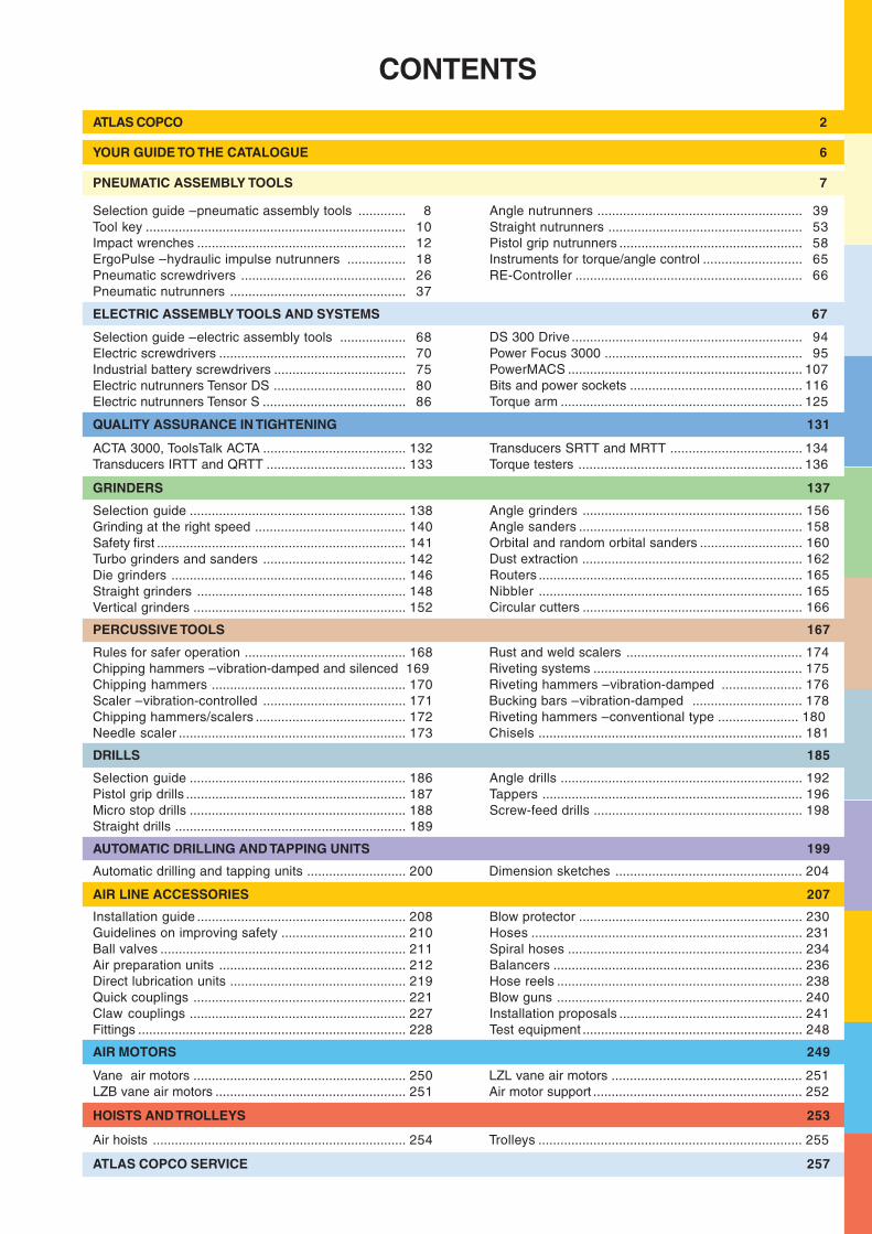
CONTENTS
Selection guide – pneumatic assembly tools ............. 8Tool key ....................................................................... 10Impact wrenches ......................................................... 12ErgoPulse – hydraulic impulse nutrunners ................ 18Pneumatic screwdrivers ............................................. 26Pneumatic nutrunners ................................................ 37
ATLAS COPCO 2
GRINDERS 137
Selection guide ........................................................... 138Grinding at the right speed ......................................... 140Safety first .................................................................... 141Turbo grinders and sanders ....................................... 142Die grinders ................................................................ 146Straight grinders ......................................................... 148Vertical grinders .......................................................... 152
Rules for safer operation ............................................ 168Chipping hammers – vibration-damped and silenced 169Chipping hammers ..................................................... 170Scaler – vibration-controlled ....................................... 171Chipping hammers/scalers ......................................... 172Needle scaler .............................................................. 173
Selection guide ........................................................... 186Pistol grip drills ............................................................ 187Micro stop drills ........................................................... 188Straight drills ............................................................... 189
Installation guide ......................................................... 208Guidelines on improving safety .................................. 210Ball valves ................................................................... 211Air preparation units ................................................... 212Direct lubrication units ................................................ 219Quick couplings .......................................................... 221Claw couplings ........................................................... 227Fittings ......................................................................... 228
AUTOMATIC DRILLING AND TAPPING UNITS 199
DRILLS 185
Angle grinders ............................................................ 156Angle sanders ............................................................. 158Orbital and random orbital sanders ............................ 160Dust extraction ............................................................ 162Routers ........................................................................ 165Nibbler ........................................................................ 165Circular cutters ............................................................ 166
Angle nutrunners ........................................................ 39Straight nutrunners ..................................................... 53Pistol grip nutrunners .................................................. 58Instruments for torque/angle control ........................... 65RE-Controller .............................................................. 66
Rust and weld scalers ................................................ 174Riveting systems ......................................................... 175Riveting hammers – vibration-damped ...................... 176Bucking bars – vibration-damped .............................. 178Riveting hammers – conventional type ...................... 180Chisels ........................................................................ 181
Angle drills .................................................................. 192Tappers ....................................................................... 196Screw-feed drills ......................................................... 198
Blow protector ............................................................. 230Hoses .......................................................................... 231Spiral hoses ................................................................ 234Balancers .................................................................... 236Hose reels ................................................................... 238Blow guns ................................................................... 240Installation proposals .................................................. 241Test equipment ............................................................ 248
PERCUSSIVE TOOLS 167
AIR LINE ACCESSORIES 207
Automatic drilling and tapping units ........................... 200 Dimension sketches ................................................... 204
AIR MOTORS 249
Vane air motors .......................................................... 250LZB vane air motors .................................................... 251
LZL vane air motors .................................................... 251Air motor support ......................................................... 252
HOISTS AND TROLLEYS 253
Air hoists ..................................................................... 254
YOUR GUIDE TO THE CATALOGUE 6
PNEUMATIC ASSEMBLY TOOLS 7
Selection guide – electric assembly tools .................. 68Electric screwdrivers ................................................... 70Industrial battery screwdrivers .................................... 75Electric nutrunners Tensor DS .................................... 80Electric nutrunners Tensor S ....................................... 86
DS 300 Drive ............................................................... 94Power Focus 3000 ...................................................... 95PowerMACS ................................................................ 107Bits and power sockets ............................................... 116Torque arm .................................................................. 125
QUALITY ASSURANCE IN TIGHTENING 131
ELECTRIC ASSEMBLY TOOLS AND SYSTEMS 67
ACTA 3000, ToolsTalk ACTA ....................................... 132Transducers IRTT and QRTT ...................................... 133
Transducers SRTT and MRTT .................................... 134Torque testers ............................................................. 136
Trolleys ........................................................................ 255
ATLAS COPCO SERVICE 257

2
Your global partner – locally
Atlas Copco assembly tools are used in manufacturing plants in a wide range of industries.
Twice the power, half the weight! GTG turbine grind ers offer an extremely high rate of ma te ri al rem oval.
Tensor electric tools are a key to error proofi ng and productivity.
PowerMACS tightening systems are supplied to the automotive industry worldwide.
Our global organization is dedicated to ser ving you, wherever you are. By combining a strong local presence with the lat est in for ma tion technology, we have simplifi ed all aspects of interfa-cing with a tool supplier. In oth er words, it is easy to do bu si ness with us.
Customer centersWe know the importance of being close to our customers. For this rea son we have fully equipped Customer cen ters in many parts of the world. Here, in ad di tion to our com-plete range of products and services, we of fer glo bal pro-ject ma na ge ment for mul ti na tio nal customers.
Application centersAdvances in tight ening technology de-m and the high est level of eng i nee ring ex per ti se. Using At las Copco core components, specialized Application cent ers aro und the globe confi gure At las Copco as-sembly systems as com-plete assembly stations for the automotive industry.
Wherever you areAtlas Copco power tools and assembly systems are available through our own sa les companies in some 50 countries and a network of in de pen dent distributors in an additional 90 countries.
Making your tool selectionOn our website www.atlascopco.com/tools you will fi nd tool selection guides that help you choose precisely the correct tool for your application. Also available is a range
of drawings, from simp le di men si on sketches to 3D CAD drawings.
After your purchaseAt las Copco ServAid streamlines your tools maintenance. ServAid is a CD-ROM containing an illustrated spare parts list. With ServAid in your com-
puter you have comprehensive parts data at your fi ng er tips.
Talk to your local distributorUsing our e-solution, AC Connect, your distributor
can give you a lightning fast re spon se to your inquiries, and the best possible ser vi ce.
www.at
lascopco.com – your gateway to our on-line catalogue
Enginledning.indd 2 2003-11-28, 14:05:11Cyanblå (processfärg)Magentaröd (processfärg)Gul (processfärg) Svart (processfärg) Auto

3
The power of choice...
Atlas Copco regularly introdu-ces innovative new designs. We currently have nearly 300 active basic patents and regis-tered designs.
Before dispatch each Atlas Copco tool is subjected to rigorous quality control.
Our Tierp plant in Sweden is one of the most effi cient of its kind in the world. Production is order-driven and a dedicated workforce keeps throughput times short.
...is in your hands!
Atlas Copco has exactly the right power tool for your job. Make your choice from nearly 3,000 air powered, electrical and battery driven tools, assembly systems, and a wide range of acces-sories.
Innovation through interactionAtlas Copco launches more new products each year than any other tool supplier. We start by asking what you, our customers, want. We then combine your needs with our own innovative thinking and technical expertise. The result? Advanced tools offering levels of performance, reliability and safety you never thought possible.
Quality that speaks for itselfPick up one of our tools. The quality speaks for itself. Be-fore dispatch from our modern factory in Sweden, each tool is subjected to rigorous quality control. The latest equipment is used to check power, speed, accuracy and air consumption.All products are accompanied by instructions in 12 lang-
uages. Video training fi lms and pocket guides are also available in all major languages.
Ergonomics boost productivityHow productive are your operators? Change to light,
powerful, ergonomically de sig ned tools from Atlas Copco and you´ll notice an increase in individual productivity.
Less physical strainAtlas Copco has a long tradition of ergonomic tool design. Handle de-signs that optimize the transfer of high feed forces from the hand-arm sys tem direct to the work-piece substantially reduce phy-sical strain on the operator. Noise and vi bra tion are minimized. Read more in
our book, "Power Tool Ergonomics".
Lubrication-freeMany Atlas Copco tools are lubrication-free, thus eli mi na ting oil mist from the work area.
Enginledning.indd 3 2003-11-21, 13:26:54Cyanblå (processfärg)Magentaröd (processfärg)Gul (processfärg) Svart (processfärg) Auto

4
Who cares about your productivity?
Atlas Copco offers a com-plete range of calibration services in compliance with ISO 17025 for all your tools and equipment.
Our aim is to provide service that will keep your plant running effi ciently and smoothly.
Call us and we´ll be there. We´re as close as your phone.
We do – it drives our businessAll aspects of our ope ra tions, from product development to glo bal customer sup port, are dri ven by our de ter mi na tion to raise productivity in your plant. Our tools and systems will keep you ahead.
A unique commitmentWhen you purchase Atlas Copco tools, it´s just the be-ginning of a long and profi table part nership. We get to know your process, your needs and objectives. In this way we can make a genuine contribution to raising your productivity.
International operation?At las Copco glo bal service agree-ments make life simp le. Unique among tool sup pli ers, we prov ide a com mon qua-lity stan dard for all tool ser vi ce we prov ide, worldwide.
Maximizing uptimeOur mis sion is to help maximize uptime in your plant.
We´re standing by to prov ide: On-site or off-site ser vi ce and repairs.
Calibration and certifi cation. Power tool surveys.
Preventive maintenance. Tightening and joint analysis. Operator training. Full service agreements.
Rapid deliveriesPlace an or der with your local Atlas Copco
offi ce before 4 pm local time. Your new tools or spare parts will be despatched the same day
from our cen tral tool warehouse in Belgium. Our network of re gi o nal war ehou ses enables us to offer a similar ser vi ce to customers in other parts of the world.
Enginledning.indd 4 2003-11-21, 13:27:02Cyanblå (processfärg)Magentaröd (processfärg)Gul (processfärg) Svart (processfärg) Auto

5
Atlas Copco has an overall quality target: To attain maximum quality at all stages – from initial develop-ment to spare part deliveries.
Proof of company excellenceThe ISO 9001 Certifi cate confi rms that Atlas Copco Tools product company conforms to the Quality Standard ISO 9001. Our quality policy is:
To fulfi ll customers´ expectations. To deliver problem-free products at the right time. To continuously improve our products and services. To have motivated personnel with clearly defi ned goals.
In effect it means you know what you´re getting. Carefully specifi ed manufacturing processes guarantee that every product leaving our factory meets exactly the same stan-dards of quality and performance.
EC declaration of conformityFrom January 1, 1995, all machines produced by Atlas Copco conform with EC Machine Directive 98/37/EC which focuses on safety.
Each Atlas Copco tool bears the CE marking and is
accompanied by detailed operator´s instructions and a declaration of conformity. This is your guarantee that it conforms to the relevant EC Directives.
Our obligations The manufacturer must ensure that the machine is
designed in conformance with the standards laid down for the machine type in question.
The machine must be accompanied by a declaration of conformity.
The design project must be thoroughly documented. The sign affi xed to the machine must contain the
following basic information:
Name and address of manufacturer. Product designation and technical data, defi ned in the relevant standard. The CE marking. Country and year of manufacture.
The machine must be accompanied by Operator´s Instructions warning of possible hazards when the machine is in use.
The instructions must also include a declaration of noise and vibration based on tests performed according to test codes such as EN standards or other recognized standards. The instructions must be written in all EC langua ges.
How we measure noise and vibrationWhen measuring noise, Atlas Copco uses the standard ISO 15744. To the measured level, 3 dB(A) can be ad-ded to incorporate variations in production and method. The fi gure given in this catalogue is the measured sound pressure level. If the measured value exceeds 85 dB(A), we also state the sound power level which is 13 dB(A) higher than the sound pressure level. The stan dard des-cribes how to calculate this fi gure.
Vibration is measured using the test code ISO 8662. The vibration value stated consists of a measured value and a tolerance. The tolerance varies from machine to machine and is given in the instructions.
If the registered value is less than 2.5 m/s2, we nor-mally just state less than 2.5 m/s2, because values less than 2.5 m/s2 indicate minimal risk from vibration.
EnvironmentAs a part of At las Copco´s environmental po li cy, At las Copco Tools and Assembly Systems product com pany has received the ISO 14001 certifi cation early 2002. We continuously work with improvements such as:
Energy effi ciency in our production as well as in our products.
Supplier evaluation from an environmental perspective.Reduction of hazardous substances both in our produc-
tion and in our products.Information to our customers in the environmental area.Environmental awareness training of all employees.
Name and addressof manufacturer
Designation ofseries or type
Serial number Year of manufacture
User safetywarnings inthe form ofpictograms
CE marking
You know what you´re getting
Enginledning.indd 5 2003-11-21, 13:27:26Cyanblå (processfärg)Magentaröd (processfärg)Gul (processfärg) Svart (processfärg) Auto

6
LENGTH 1 in = 0.0254 m 1 m = 39.3701 in 3.2808 ft 1 mm = 0.0393701 in
WEIGHT 1 lb = 0.4536 kg 1 kg = 2.2046 lb
TORQUE 1 kpm = 9.8067 Nm 1 Ft lb = 1.3558 Nm 1 In lb = 0.1130 Nm 1 Nm = 0.1020 kpm 0.7376 ft lb
PRESSURE 1 bar = 100 kPa 1 kp/cm2 (at) = 98.0665 kPa 1 psi = 6.8948 kPa 0.01 bar 1 kPa = 0.0101972 kp/cm2 (at)
POWER 1 kpm/s = 9.8067 W 1 hp = 745.7 W 101.972 kpm/s 1 kW = 1.3410 hp
FLOW 1 m3/min = 16.6667 l/s 1 cfm = 0.4720 l/s 1 m3/h = 0.2778 l/s 1 l/s = 2.1189 cfm
Your guide to the catalogueAccessories includedUnder this heading a specifi cation is given for each type of tool and of the parts (nipples, keys, guards, etc.) supplied with the tool.
Instructions and a list of spare parts are always included in the package.
Optional accessoriesHere you will fi nd most of the accessories speci-fi ed. They are dependent on the job the tool is to be used for and they have to be orde red separately.
Air consumptionThe air consumption of the tools is stated in litres per second, l/s, and relates to free air, i.e., the compressed air expanded to atmospheric pressure. Unless otherwise stated, the fi gures are valid at a working pressure of 6.3 bar and indicate the maximum air consumption.
Maximum air consumption is valid for the tool without a speed governor when idling, i.e., when the tool is running at no load. A tool with a speed governor, has the maximum air consumption at the maximum power out put.
SpeedThe tool speeds are indicated in revolutions per min ute, r/min, and indicate the idling speed, i.e., the speed at which the tool runs at no load and at a working pressure of 6.3 bar, if not otherwise specifi ed. The speed at max. output is 50% of the idling speed for tools without a speed governor and 80-90% of the idling speed for tools with a speed governor.
Selected service kits to orderUnder this heading, servi ce kits for the
most frequent servi ce jobs done on the tool in question are listed.
VibrationsNowadays it is known that vibrations
are not only unpleasant for the opera-tor, but in the long term can also cause
vascular problems.We consider ourselves the leaders in the industry with
regards to our efforts and dedication towards fi n ding a so-lution to this problem. We are convinced that we of fer tools with lower vibrations than our competitors and our claim to offer tools with low vibrations is based on this comparision. Vibrations are aggravated by factors beyond our control such as poor maintenance, pirate parts, unbalanced grin-ding wheels, etc.
We are therefore unable to guarantee that the use of our tools will never cause vascular problems. Therefore, even if you choose our tools, you still need to monitor your work for ce. The vibration values indicated in this catalogue are measured in accordance with ISO 8662. This standard offers guidance on how to conduct laboratory measure-ments. To be able to make comparisons, the stan dard has been developed to give reproducible results.
Sound levelMost values indicated in this catalogue are measured in accordance with the Pneurop test code. From 2002 the of-fi cial test code for sound measurements is changed to ISO 15744. The differences between the two standards are however minor, and are in most cases negligible. When we sta te that a sound level is low we obviously relate this to competitors´ similar tools. We do not imply that exten-ted use of our tools will never cause hearing impairment. Particularly sin ce in many applications the sound from the process is higher than the unloaded tool noise. It is there-fore always advisable to wear hea ring protection.
Ergonomists are involved at every step of the tool development process.
Noise level testing in the acoustics laboratory.
Enginledning sid6.indd 2 03-11-28, 08.03.34Cyanblå (processfärg)Magentaröd (processfärg)Gul (processfärg) Svart (processfärg)

Get it together fast!
With ergonomically designed screwdrivers, pulsetools, nutrunners and impact wrenches from AtlasCopco. Correct grip diameters reduce reactionforces, vibration and noise levels. High power-to-weight ratios ensure maximum operator comfort.
Contents PageSelection guide – assembly tools .................... 8
Basic tightening technique ............................... 9
Tool key ......................................................... 10
Selection guide – impact wrenches ............... 12
Impact wrenches ........................................... 13
Hydraulic impulse nutrunners – ErgoPulse ....... 18
Selection guide – ErgoPulse .................... 20, 23
Pneumatic screwdrivers ................................. 26
Selection guide – pneumatic screwdrivers ..... 27
Pneumatic nutrunners .................................... 37
Angle nutrunners ............................................ 39
Straight nutrunners ........................................ 53
Pistol grip nutrunners ..................................... 58
Instruments for torque/angle control, Focus ..... 65
RE-Controller .................................................. 66
Pneumaticassembly tools

8
500 1000 500010050.50.1
M1.6 M2M2.5
M3 M4 M5 M6 M8M10 M14
M12 M16 M20M24
M30M36
M42
1 17TWIST/LUF
0.1 12LUM
1 10ETB
5 13EPA
0.17Nm 0.35 0.7 1.2 2.9 5.7 9.8 24 47 81 128197
385665
13102280
3640
1 10 50
4 ErgoPulse 450
2 TWIST HRD 18
LTV 5750.5
LMP6 4100
5 LTD 1500
5000LMS7
22 650LTS
2 28BTV
PNEUMATIC ASSEMBLY TOOLSSelection guide
IMPACT WRENCHES (LMS, LTS)Impact wrenches are suitable for general assembly and rep-air jobs when a powerful and lightweight tool is required.They are the best tools for loosening joints.
Atlas Copco LMS and LTS reversible impact wrenches canhandle tough tightening and loosening jobs quickly, with mini-mum operator fatigue. The LMS non shut-off range is desig-ned for all-purpose tightening with high availability. To cut tight-ening times, independent of operator influence, the LTSmodels should be used.IMPULSE TOOLS (ErgoPulse)Suitable both for general assembly and serial production.They have the same advantages as impact wrenches withhigher accuracy. In addition you will have a tool with goodergonomics which means lower sound levels and lessvibrations. Pulse tools also have a longer service life.SCREWDRIVERSThe biggest range on the market when it comes to extremelyaccurate screwdrivers with ergonomic design. All models arelubrication-free.
For all kinds of jobs involving smaller screw sizes, up to M6.
Shut-off control (LUM, ETB)Best practice in most cases, especially for machine screwsand screws in plastic. Very high accuracy and lowest bit con-sumption.Slip clutch (TWIST/ LUF)Best for sheet metal screws, wood screws or self-tappingscrews.Direct drive (TWIST/LUF HRD)The low cost alternative for wood and self-drilling screws.
NUTRUNNERSAngle type (LTV)Suitable for high volume serial production.
Extremely good accuracy, small angle head, suitable for usewhere space is limited. Low sound and vibration levels.Pistol grip type (LMP, LTP)An outstanding tool for fast and extremely accurate assem-bly. A low weight alternative with extremely high torquecapacity and low sound level.
13
15
19
35
34
28
73
72
74
39
58
53
IMPACT WRENCHESNon shut-off
Shut-off
PULSE TOOLS
SCREWDRIVERSDirect drive
Slip clutch
Shut-off controll
BATTERY TOOLSShut-off control,pistol grip
Shut-off control,angle
Pulse tools
NUTRUNNERSAngle head type
Pistol grip type
Straight type
Recommendedtorque bolt grade 8.8
Recommended torque boltgrade 8.8 Page

9
The materialThe material is decisive for the choice of which type of screwand fastening tools you should choose. The most commonmaterials are steel, aluminium, plastic, wood and varioustypes of construction material. Different materials withstand
different clamping forces. The clampingforce is the force that holds the joint
together and assures its function.Clamping force is attained in prac-tice by transmitting a specifictorque. Out of the total torqueapplied in tightening, roughly10% is consumed for clampingforce, while the remaining 90%is used in overcoming the friction.
The frictionTo assure the best possible results
you should endeavour to achieve uni-form quality and friction in the joint. This means that you mustconsider the dimensions of predrilled and punched holes,threads, washers etc. If there is too much variation in the di-mensions, and thus in the friction, this could be very costly.
The screw/boltIn most constructions the screw is the weakest link in the joint.If anything happens, it is usually cheaper to replace screws.There are exceptions, however, such as when materials likesheet metal and plastic are involved, when the screw is thestrongest link. Replacement of parts with defective threadscan be expensive. For such applications, it is therefore veryimportant to work with a tool that has an accurate clutch.
Hard and soft jointsA joint is usually classified as either hard or soft. A hard jointis tightened to full torque through a tightening angle ofroughly 30o after the screw has reached snug level. In a softjoint, the screw sometimes has to be tightened more than twocomplete turns before the full torque is achieved. The sametools often give different torque values on hard and soft jointsrespectively. This difference in torque values is generallyknown as “mean shift”.
By measuring the torque from a series of tightening opera-tions on the same joint, a measure is obtained of how accu-
rately the tool can repeat a tightening. This is known as thescatter of the tool.
For more information about test procedure, see ISO 5393.
The scatter is small for a high quality tool, and wide for alow quality tool
Basic tightening technique
TORQUE RECOMMENDATIONSThe torque is important to ensure the required clamping force.These tables show the recommended torque for the mostcommon types of screws and bolts.
SCREWSRecommended max tightening torque (Nm) for untreatedoil-smeared screws (friction coefficient = 0.125).
Metric coarse thread. The torque corresponds to approximately62% of tensile stress.
M-THREADED SCREWS/BOLTSTightening torque Nm, according to ISO 898/1
Bolt grade Bolt gradeThread 3.6 4.6 4.8 5.8 8.8 10.9 12.9 Thread 4.6 4.8 5.8 8.8 10.9 12.9
M1.6 0.05 0.065 0.086 0.11 0.17 0.24 0.29 M14 48 58 80 128 181 217M2 0.10 0.13 0.17 0.22 0.35 0.49 0.58 M16 74 88 123 197 277 333M2.2 0.13 0.17 0.23 0.29 0.46 0.64 0.77 M18 103 121 172 275 386 463M2.5 0.20 0.26 0.35 0.44 0.70 0.98 1.20 M20 144 170 240 385 541 649
M3 0.35 0.46 0.61 0.77 1.20 1.70 2.10 M22 194 230 324 518 728 874M3.5 0.55 0.73 0.97 1.20 1.90 2.70 3.30 M24 249 295 416 665 935 1120M4 0.81 1.10 1.40 1.80 2.90 4.00 4.90 M27 360 435 600 961 1350 1620M5 0.60 2.20 2.95 3.60 5.70 8.10 9.70 M30 492 590 819 1310 1840 2210
M6 2.80 3.70 4.90 6.10 9.80 14.0 17.0 M36 855 1030 1420 2280 3210 3850M8 8.90 10.50 15.0 24.0 33.0 40.0 M42 1360 2270 3640 5110 6140M10 17.0 21.0 29.0 47.0 65.0 79.0 M45 1690 2820 4510 6340 7610M12 30.0 36.0 51.0 81.0 114.0 136.0 M48 2040 3400 5450 7660 9190
PNEUMATIC ASSEMBLY TOOLSSelection guide
For more information please contact Atlas Copco.
40% 50%
Friction lossunder head
Friction lossin thread
Clamping force
10%
MEAN SHIFTMean shift
Torque
Expectedtorque
level
Soft joint720˚
Hard joint30˚
Angle
Number oftightenings
Low quality tool
Applied torque (Nm)
Number oftightenings
High quality tool
Applied torque (Nm)
GENERALPerformance figures for all pneumatic assembly tools areat a working pressure of 6.3 bar.

10
TOOL KEY
Handle/grip design
Reversible or non reversible
Tool, motor or clutch size
Hydraulic impulse nutrunners
The designator/ordering number of Atlas Copco assembly tools is a combination of letters and numbers indicating various properties and char acte ris tics of the tool concerned.
Below is a guide showing the general signifi cance of each group of letters/numbers and specifi c guides to the indivi-dual tool types.
HR = Pistol grip, reversibleSR = Straight, reversibleHRF = Pistol grip, reversible, air-on-topHRX = Pistol grip, reversible, forward handle
EP 8 PTS 55 HR 10 RE
C = Single bladed pulse unitX = Double bladed pulse unitXS = Double or triple bladed pulse unit, extra strongPT = Piston rollers, shut-offPTS = Pis ton roll ers, shut-off, ex tra strongPTX = Pis ton roll ers, shut-off, strong and light
Square drive size10 = 3/8"13 = 1/2"20 = 3/4"42 = 1/4" female hex, quick change chuck43 = 7/16" female hex, quick change chuck
Signal port
ScrewdriversEPA = Hydraulic impulse tool,
pistol gripETB = Battery screwdriver, pistol gripLTV = Angle headLUM = Shut-off clutchTWIST = Slip clutchCOMBI = Direct driveLUF = Slip clutch
X = Forward handleF = Air on topD = Direct drive
HR = Pistol grip, reversiblePR = Straight, reversible, push startSR = Straight, reversible
Clutch size 6 = 1/4" male hexU = Non push-startQ = Quick change chuckI6 = 1/4" female hex42 = 1/4" female hex, quick change chuck
Speed03 = 300 rpm15 = 1500 rpm
Sig nal port
Tool type
Speed Square drive size
LTP 51 H R 001 25
Pulse tool Tool size Max torque
LUM 21 HR X 15 U RE
toolkpneu.indd 10 2003-11-19, 12:33:58Cyanblå (processfärg)Magentaröd (processfärg)Gul (processfärg) Svart (processfärg)

11
TOOL KEY
LMS = Non shut-offLTS = Shut-off
For heavy duty use
LMS 06 HR 10 HD
Tool size
HR = Pistol grip, reversibleSR = Straight, reversibleGIR = Rear grip, inside triggerGOR = Rear grip, outside triggerGR = Rear grip
Square drive size 6 = 1/4"10 = 3/8"13 = 1/2"20 = 3/4"25 = 1"38 = 1 1/2"42 = 1/4" female hex, quick change chuck43 = 7/16" female hex, quick change chuck
Impact wrenches
Nutrunners
L = Pneumatic Motor size R, SR = ReversibleN, S = Non reversibleHR = Reversible (pistol grip)H = Non reversible (pistol grip)
L T V 2 8 X R 29 10 Options
V = Right angleD = In-lineP = Pistol gripC = CrowfootO = Tube nutR = RatchetK = Worm-drive
X =High speedoption
Speed001 = 100 rpm002 = 200 rpmetc.or
Torque10 = 10 Nm15 = 15 Nmetc.
Square drive size 6 = 1/4" 8 = 5/8"10 = 3/8"12, 13 = 1/2"19, 20 = 3/4"25 = 1"38 = 1 1/2"42 = 1/4" female hexQ = 1/4" quick chuck
RE = Signal portFS = Flush socketHAD = Hold-and-driveTS = Built-in transducer/signal
lights etc.AS = Angle encoder/signal lights
T = Shut-offB,M = Stall
Ge ne ra tion
toolkpneu.indd 11 2003-11-19, 12:34:04Cyanblå (processfärg)Magentaröd (processfärg)Gul (processfärg) Svart (processfärg)

12
■ =
■ =
M6 M8 M10 M12 M14 M16 M18 M20 M22 M24 M27 M30 M36 M42 M45 M48
Nm 9.8 24 47 81 128 197 275 385 518 665 961 1310 2280 3640 4510 5450
LMS LMS06 LMS17 LMS17 LMS27 LMS37 LMS37 LMS47 LMS57 LMS57 LMS61 LMS61 LMS64 LMS86 LMS86 LMS86 LMS86LMS06 LMS17 LMS27 LMS37 LMS37 LMS47 LMS57 LMS57 LMS57 LMS64 LMS64 LMS64 LMS86
LTS LTS17 LTS17 LTS27 LTS27 LTS37 LTS57 LTS57 LTS57LTS17 LTS17 LTS37 LTS37 LTS37 LTS57 LTS57
M6 M8 M10 M12 M14 M16 M18 M20 M22 M24 M27 M30 M36 M42 M45
Nm 14 33 65 114 181 277 386 541 728 935 1350 1840 3210 5110 6340
LMS LMS06 LMS17 LMS27 LMS27 LMS37 LMS37 LMS47 LMS57 LMS61 LMS61 LMS64 LMS86 LMS86 LMS86 LMS86LMS17 LMS17 LMS27 LMS37 LMS47 LMS47 LMS57 LMS61 LMS64 LMS64 LMS86
LTS LTS17 LTS17 LTS27 LTS37 LTS57 LTS57 LTS57LTS17 LTS27 LTS37 LTS37 LTS57 LTS57
M6 M8 M10 M12 M14 M16 M18 M20 M22 M24 M27 M30 M36 M42
Nm 17 40 79 136 217 333 463 649 874 1120 1620 2210 3850 6140
LMS LMS06 LMS17 LMS27 LMS27 LMS37 LMS47 LMS57 LMS61 LMS61 LMS64 LMS86 LMS86 LMS86 LMS86LMS17 LMS17 LMS27 LMS37 LMS47 LMS57 LMS61 LMS64 LMS64 LMS86
LTS LTS17 LTS17 LTS27 LTS37 LTS57 LTS57LTS17 LTS27 LTS37 LTS57 LTS57
8.8
10.9
12.9
IMPACT WRENCHESSelection guide
Atlas Copco´s powerful, high-speedimpact wrenches are designed to cutproduction times by providing fast run-down and quick tightening.
Impact wrenches build up torque injoints through a series of rotary impacts.The torque obtained depends on:❏ Air pressure.❏ Tightening time on the actual joint.
These factors should be consideredwhen choosing an impact wrench.
As a general rule, if a wrench impactslonger than 5 seconds on a fastener, alarger wrench should be used or ashorter life will result.
This guide will assist you in recom-mending an impact wrench for a specificapplication.
HEAVY DUTY
EXTRA HEAVY DUTY
The torque figures are normal tightening torque for untreated oil-smeared and rust-protected bolts and nuts inthe most common strength grades. The torque figures correspond to approximately 63% of tensile stress.

13
LMS27
LMS06 HR
LMS06 SR
6 bar5 bar4 bar
Nm
min 1s max 5ss
LMS37
LMS Operating Range
The tightening time should not exceed5 seconds, to avoid excess wear of the tool.
ACCESSORIES INCLUDEDSilenced air exhaust through handle
Hose fitting
OPTIONAL ACCESSORIESPage 16-17
SELECTED SERVICE KITSPage 17
a Female hex. quick change chuck.
* Basic tools of the range, cover most needs.
Dis-Air con- Recom- tance
Bolt Square Recommended Length sumption mended centrecapa- drive torque range Max. Free Weight excl under load hose tocity size torque Impacts speed anvil size side
Model mm in Nm ft lb Nm per min r/min kg lb mm l/s cfm mm mm Ordering No.
LMS06 SR10 6-8 3/8 7- 30 5- 22 55 2100 12500 0.9 2.0 182 4 8 6.3 20 8434 1060 12LMS06 HR10 6-8 3/8 7- 30 5- 22 55 2100 13500 0.9 2.0 184 4 8 6.3 20 8434 1060 04*LMS06 HR10-HD 6-8 3/8 7- 30 5- 22 55 2100 10000 0.9 2.0 184 4 8 6.3 20 8434 1060 08LMS06 HR42 6-8 1/4a 7- 30 5- 22 55 2100 13500 0.9 2.0 184 4 8 6.3 20 8434 1060 20LMS06 HR42-HD 6-8 1/4a 7- 30 5- 22 55 2100 10000 0.9 2.0 184 4 8 6.3 20 8434 1060 16LMS17 HR10 10 3/8 10- 70 7- 52 110 1260 10000 1.7 3.8 141 10 21 10.0 24 8434 1170 60LMS17 HR13 10 1/2 10- 70 7- 52 110 1260 10000 1.7 3.8 141 10 21 10.0 24 8434 1170 29LMS27 HR13 12 1/2 30-180 22-133 220 1200 8700 2.1 4.6 142 10 21 10.0 29 8434 1270 02*LMS27 HR43 12 7/16a 30-180 22-133 220 1200 8700 2.1 4.6 142 10 21 10.0 29 8434 1270 77LMS37 HR13 14-16 1/2 40-340 30-251 480 1200 7800 2.7 6.0 165 13 27 10.0 33 8434 1360 41*LMS37 HR16 14-16 5/8 40-340 30-251 480 1200 7800 2.7 6.0 165 13 27 10.0 33 8434 1370 01
Air inlet thread inch: LMS06 = 1/4", LMS17, LMS27 and LMS37 = 3/8".
HD = Suitable for soft joints.
LMS06 – LMS37Atlas Copco series of impact wrenchesare designed for the toughest conditions.They are built to provide the ultimate independability and a long, trouble-freeservice life. There is nothing that matchesthe Atlas Copco impact wrench when itcomes to flexibility, capacity-to-weightratio and simplicity in use and main-tenance.❏ Fast tightening and disassembly.❏ Wide torque range (7-480 Nm).❏ Low weight.❏ Negligible reaction force.❏ Soft-start throttle.❏ LMS06 – LMS27 are lubrication-free.
IMPACT WRENCHESNon shut-off type – Reversible

14
LMS86 GIR
LMS64 HR
LMS61 HR
LMS47 HR
LMS64 GR
LMS57 HR
LMS47 – LMS86These tools provide enormous power,yet you are in full control, and there isvirtually no reaction force during tight-ening. The torque is applied to the joint,not your wrist. All Atlas Copco impactwrenches have a wide torque range, soeach tool can be adjusted to handlemany applications.❏ Fast tightening and disassembly.❏ Wide torque range (70-10000 Nm).❏ Low weight.❏ Negligible reaction force.❏ Soft-start throttle.
ACCESSORIES INCLUDEDSilenced air exhaust through handle(LMS47/57/61)
Hose fitting
OPTIONAL ACCESSORIESPage 16-17
SELECTED SERVICE KITSPage 17
a Spline drive No. 5.b Spline drive No. 4.
GOR = Outside trigger
GR/GIR = Inside trigger
Air inlet thread inch: LMS47, LMS57 and LMS61 = 3/8", LMS64 and LMS86 = 1/2".
* Basic tools of the range, cover most needs.
Dis-Air con- Recom- tance
Bolt Square Recommended Length sumption mended centrecapa- drive torque range Max. Free Weight excl under load hose tocity size torque Impacts speed anvil size side
Model mm in Nm ft lb Nm per min r/min kg lb mm l/s cfm mm mm Ordering No.
LMS47 HR20 16-19 3/4 70- 460 52- 339 550 900 4800 3.5 7.7 170 14 30 12.5 37 8434 1470 42LMS57 HR20 18-20 3/4 100- 500 74- 369 900 960 4500 4.3 9.5 189 16 34 12.5 38 8434 1570 09*LMS57 HR25 18-22 1 100- 650 74- 479 900 960 4500 4.3 9.5 189 16 34 12.5 38 8434 1570 41LMS61 HR20 20-24 3/4 300-1300 220- 960 1800 900 4000 5.1 11.2 212 12 25 12.5 44 8434 1611 00LMS61 HR25 20-24 1 300-1300 220- 960 1800 900 4000 5.1 11.2 212 12 25 12.5 44 8434 1610 00LMS61 HRS4 20-24 1 1/4b 300-1300 220- 960 1800 900 4000 5.1 11.2 212 12 25 12.5 44 8434 1612 00LMS64 HR25 24-32 1 400-1400 295-1030 2300 600 3100 9.0 20.0 195 21 44 12.5 57 8434 1640 03LMS64 GR25 24-32 1 400-1400 295-1030 2300 600 3100 9.0 20.0 280 21 44 12.5 57 8434 1641 02*LMS64 S GR25 24-32 1 400-1500 295-1100 2300 620 3380 9.0 20.0 280 35 73 12.5 57 8434 1641 06LMS64 GRS5 24-32 1 5/8a 400-1400 295-1030 2300 600 3100 9.0 20.0 280 21 44 12.5 57 8434 1641 44LMS64 S GRS5 24-32 1 5/8a 400-1500 295-1100 2300 620 3380 9.0 20.0 280 35 73 12.5 57 8434 1641 08LMS86 GOR38 32-45 1 1/2 1000-5000 737-3688 10000 450 3720 16.4 36.0 376 29 61 16.0 63 8434 1860 14LMS86 GIR38 32-45 1 1/2 1000-5000 737-3688 10000 450 3720 16.4 36.0 376 29 61 16.0 63 8434 1860 22*LMS86 GORS5 32-45 1 5/8a 1000-5000 737-3688 10000 450 3720 16.4 36.0 376 29 61 16.0 63 8434 1860 16LMS86 GIRS5 32-45 1 5/8a 1000-5000 737-3688 10000 450 3720 16.4 36.0 376 29 61 16.0 63 8434 1860 24
IMPACT WRENCHESNon shut-off type – Reversible

15
LTS27 HR43
LTS17 HR13
Nm200
150
100
50
002 03 04 05 06 07 08 09 10
Nm
min 1s
max 5s
bar
+
–
LTS17 – LTS27Equipped with automatic shut-off, the LTSmodels provide a perfect result, everytime. This means proper tightening withless risk for over-tightening due to ope-rator influence, improving joint quality aswell as operator confidence.❏ Automatic shut-off shortens tightening
time.❏ Consistent torque accuracy.❏ No over-torquing.❏ Low weight.❏ Adjustable torque settings (22-165 Nm).❏ LTS17 and LTS27 are lubrication-free.The purpose of the torsion bar principleis to increase the bounce angle of theimpact mechanism. The tool shuts off onceit has reached the pre-set bounce angle.
IMPACT WRENCHESShut-off type – Torsion bar principle
a Female hex. quick change chuck – 1/2" squaredrive on torsion bar.
b Min torque at 3 bar air pressure and min setting oftorque control mechanism.
LTS17 and -27 torsion bar –bounce angle shut-off
LTS27 HR43Female hexagon quick-change chuckfor separate torsion bars with 1/2"square drive. The design is speciallysuitable for the tightening of differentbolt sizes at the same work place.
LTS17, -27 HR13 (10) built-intorsion barThe anvil of the impact mechanism isextended with a built-in torsion bar toincrease accuracy and reduce vibrationlevel. These types are designed for fre-quent tightening of the same bolt size.
ACCESSORIES INCLUDEDSilenced air exhaust through handleHose fittingTorsion bar No. 06 LTS27 HR43Adjusting key LTS17 and LTS27
TorqueTorsion bar No. Nm Ordering No. Colour of bar
02 60 4250 1230 82 orange03 75 4250 1230 83 yellow04 90 4250 1230 84 green05 100 4250 1230 85 blue06 115 4250 1230 86 red (Standard)07 125 4250 1230 87 orange08 140 4250 1230 88 yellow09 150 4250 1230 89 green10 165 4250 1230 90 blue
Dis-Air con- Recom- tance
Bolt Square Recommended Length sumption Air mended centrecapa- drive torque range Free Weight excl under load inlet hose tocity size Impacts speed anvil thread size side
Model mm in Nm ft lb per min r/min kg lb mm l/s cfm in mm mm Ordering No.
LTS17 HR10 8-10 3/8 22b- 45 16- 33 960 10000 2.0 4.4 214 6 13 3/8 8 24 8434 1172 19LTS17 HR13 8-10 1/2 34b- 66 25- 49 1100 10000 2.0 4.4 214 6 13 3/8 8 24 8434 1172 01*LTS27 HR13-1 10-12 1/2 50b-110 37- 82 960 9300 2.6 5.7 226 6 13 3/8 10 29 8434 1272 00LTS27 HR13-2 12-14 1/2 70b-140 52-104 1100 9300 2.6 5.7 226 8 17 3/8 10 29 8434 1272 18LTS27 HR43 10-14 7/16a 40b-165 29-123 1200 11500 2.5 5.5 164 8 17 3/8 10 29 8434 1272 59*
Val
id a
t 6 b
ar a
ir pr
essu
re
Max torque (+)
Min torque (–)
Bar No.
* Basic tools of the range, cover most needs.
LTS Adjustment Range
The tightening time should not exceed5 seconds, to avoid excess wear of the tool.
3.0 6.3

16
LTS57
LTS37
Socket holders
Dimensions
Drive Exten-size sion
Model in mm Ordering No.
Extended square drive anvil forLMS17 1/2 75 4250 1147 80ab
LMS27 1/2 75 4250 1085 80ab
LMS27 1/2 150 4250 1086 80ab
LMS37/LTS37 1/2 75 4250 1031 80ab
LMS37/LTS37 1/2 150 4250 1032 80ab
LMS37/LTS37 5/8 75 4250 1034 80ab
LMS37/LTS37 5/8 150 4250 1035 80ab
LMS47/LTS47 3/4 75 4250 1208 00LMS47/LTS47 3/4 150 4250 1209 00LMS57/LTS57 3/4 75 4250 1109 00LMS57/LTS57 3/4 150 4250 1110 00LMS57/LTS57 3/4 200 4250 1111 00LMS57/LTS57 1 75 4250 1113 00LMS57/LTS57 1 150 4250 1114 00LMS64 1 80 4250 0774 00LMS64 1 160 4250 0775 00
Spline type anvil forLMS64 1 5/8-14 – 4250 0967 80
Heavy duty anvil (thru hole) forLMS37/LTS37 1/2 80 4250 1041 01
Dimensions
Drive Exten-size sion
Model in mm Ordering No.
Anvil with female hexagon quickchange chuck forLMS06 1/4 – 4250 1513 80LMS17 7/16 – 4250 1154 80LMS27 7/16 – 4250 1088 80LMS37 7/16 – 4250 1050 80c
Drivesize Length
Model in mm Ordering No.
Tool holder with square drive, for 7/16"quick change chuck, forLMS17,-27 3/8 75 4023 1210 03
1/2 75 4023 1211 03
IMPACT WRENCHESShut-off type – Added bounce energy principle
LTS37 – LTS57LTS shut-off tools automatically shut offwhen the preset torque is reached, eli-minating the need for guesswork. Placethe tool on the joint to be fastened andpress the trigger. The tool will automa-tically shut-off at a predetermined torquelevel, which provides for an operator in-dependent tightening.❏ Automatic shut-off shortens tightening
time.❏ Consistent torque accuracy.❏ No over-torquing.❏ Low weight.❏ Adjustable torque settings (80-650 Nm).The purpose of the added bounce energyprinciple is that the energy content of eachimpact is added to the next and followingimpact until the preset level is reachedand the tool shuts off.
Dis-Air con- Recom- tance
Bolt Square Recommended Length sumption Air mended centrecapa- drive torque range Free Weight excl under load inlet hose tocity size Impacts speed anvil thread size side
Model mm in Nm ft lb per min r/min kg lb mm l/s cfm in mm mm Ordering No.
LTS37 HR13 12-14 1/2 80a-340 59-250 1140 8800 3.7 8.1 200 10 21 3/8 10 33 8434 1372 41*LTS37 HR16 12-16 5/8 120a-340 88-250 1140 8800 3.7 8.1 220 10 21 3/8 10 33 8434 1372 09LTS57 HR20 18-20 3/4 200a-500 147-369 960 4600 5.3 12.0 225 13 27 3/8 10 38 8434 1571 08LTS57 HR25 18-22 1 200a-650 147-479 960 4600 5.3 12.0 225 13 27 3/8 10 38 8434 1571 40*
a Min torque at 4 bar air pressure and min setting of torque control mechanism.
Extended anvils Quick change chuck
* Basic tools of the range, cover most needs.
OPTIONAL ACCESSORIES
Ordering No.a Retainer pin – locking type 4250 0851 00b Retainer pin –
quick change type 4250 1190 00c NOTE: To be used together with reversing valve
4250 1345 95 (marked “1”) only.
SELECTED SERVICE KITSPage 17

17
3 m
SELECTED SERVICE KITSThe spare parts included inthe service kits cover a normaloverhaul of your tool. Always
have them available for a fast and eco-nomical repair.Main parts included:❏ Vane kit❏ Motor bearings❏ Gaskets❏ O-rings❏ Circlips❏ Pins etc.
Suspension yokes
Protective covers
Model Ordering No.
LMS17 4250 1503 00LMS27 4250 1273 00LMS37 4250 1213 00LMS47 4250 1338 00LMS57 4250 1282 00LMS61 4250 2464 00LMS64 4250 0828 00LTS17 4250 1410 00LTS27 HR13 4250 1411 00LTS27 HR43 4250 1340 00LTS37 4250 1337 00LTS57 4250 1339 00
Power regulators
Model Ordering No.
Power regulator valve forLMS17/LTS17 4250 1091 90LMS27/LTS27 4250 1091 91LMS37/LTS37 4250 1091 92LMS47 4250 1091 93LMS57/LTS57 4250 1091 94LTS17 4250 1091 87LTS27 4250 1091 86LTS37 4250 1091 85LTS57 4250 1091 88
Exhaust kit
Model Ordering No.
Piped-away exhaust kit forLMS06 HR 4210 2052 00
LMS17,-27,-37,-47,-57, 4250 1366 90LTS17,-27,-37,-57
Model Service kit
LMS06 4081 0008 90LMS06 SR 4081 0168 90LMS17/LTS17 4081 0204 90LMS27/LTS27 4081 0205 90LMS37/LTS37 4081 0206 90LMS47 4081 0207 90LMS57/LTS57 4081 0208 90LMS61 4081 0257 90LMS64 4081 0015 90LMS86 4081 0016 90
ACCESSORIES
Ordering No.
Model Horizontal Vertical Swivelling
LMS06 HR – – 4210 0243 00LMS17 – – 4250 1365 00LMS27 4250 0872 00 4250 1159 00 –LMS37 4250 0872 00 4250 1058 00 –LMS47 4250 0872 00 4250 1327 00 –LMS57 4250 0872 00 4250 1160 00 –LMS61 4250 0872 00 4250 1620 90 –LMS64 4250 0677 80 – –LMS86 0371 1102 00 – –LTS17 – – 4250 1365 00LTS27 4250 0872 00 – 4250 1365 00LTS37 4250 0872 00 – 4250 1253 00LTS57 4250 0872 00 – 4250 1283 00

18
EP7PTX HR
EP10XS HR
EP7XS HR
EP6XS SR
EP7/8PTS HRF
EP7/8PT/PTS HR
2
1
12
EP16XS HR
The ErgoPulse principleThe heart of a pulse toolis the hydraulic pulseunit, positioned between
the air motor and the outgoing shaft.Since the pulses are very short, there isalmost no reaction force in the handle,only the much lower motor torque istransferred to the operator’s hand. Thepulse unit increases the torque gene-rated by the motor 50-100 times!
As there is no metal-to-metal impactin a pulse tool, pulse tools provide a softer,more controlled pulse with considerablyless vibrations and noise than an impactwrench. Together with good balance andlow weight the result is a tool that isextremely comfortable to operate.
The reliability and accuracy of theErgoPulse tools make them ideal forcontinuous heavy production.
The successful combination of highproductivity and good working environ-ment.❏ Productivity – Very high speed means
short cycle times for hard to semi-softjoints.
❏ Accuracy – High torque independentof joint stiffness gives high joint quality.
❏ Reliability – Long service life with sim-ple maintenance requirements.
❏ Ergonomics:– Virtually no reaction forces.– Low noise and vibration levels.– Low weight.– Lubrication-free.
ERGOPULSEHydraulic impulse nutrunners
A complete rangeThe ErgoPulse range covers torquefrom 2-450 Nm which means that youcan tighten screws from M4 to M20.
ErgoPulse tools are available in bothshut-off and non shut-off versions. Theshut-off pulse tools – PT, PTS and PTXtypes – will shut-off the air supply assoon as the pre-set torque has beenreached. With a shut-off tool the opera-tor influence is minimized. The result isincreased accuracy and faster tightening.The non shut-off tools – C and XS types –produce pulses until the operator re-leases the trigger. They are preferred inapplications where it is an advantage forthe operator to be able to control the pro-cess by shutting off the tool manually.
Atlas Copcos pulse tools are availablein straight and pistol grip versions.
The successful combination of high productivityand good working environment
Air motor
Pulse unit

19
PT, PTS and PTX pulse unit and Twin piston mechanism Twin chamber motorshut-off system
Recommended operating areaMax recommended tightening time for apulse tool is 3 seconds. Longer timeindicates that the joint is too soft for thetool used. If so, it is recommended tochoose a bigger size of tool or anothertype of nutrunner.
Minimum recommended number ofpulses per tightening is 5. Fewer pulseswill result in increased scatter. By re-ducing the free speed with the TRIMvalve (PT/PTS/PTX) there will be morepulses per tightening and improvedaccuracy.
ERGOPULSEShut-off type
PT/PTS/PTX torque sensing shut-offsystem – an active part of the tight-ening processThe ErgoPulse PT, PTS and PTX nut-runners incorporate a shut-off systembased on retardation instead of timersor bypass valves. Torque is “sensed” bymeans of a rotatable inertial mass actingagainst an adjustable spring. When theforce of the mass is sufficient to over-come the preset force in the spring, alock pin releases a disc valve to shut offthe air supply. The result is a highlyaccurate and easily adjustable shut-offsystem.
A pulse mechanism with pistons forminimum weight and long service lifeThe ErgoPulse PT/PTS/PTX pulse unitfeatures a more efficient transfer of theimpulse energy. The design is based oncam-guided pistons and rollers and thepulse cylinder is oil-filled. The movingparts are thus completely immersed inoil, which ensures a long service life.
The unique piston principle makes thePT/PTS/PTX tools extremely light.
Twin chamber motorThe ErgoPulse PT, PTS and PTX nut-runners have a twin chamber vane mo-tor. It is designed for giving high torqueat low speed, which gives the best char-acteristics for fast, reliable and accuratetightening.
TRIM valve for enhanced performanceon hard joints and at low torque levelsThe PT, PTS and PTX tools incorporatea patented adjustable valve at the airoutlet. This feature enhances the tool’sperformance on hard joints and at lowtorque levels.
The PTS/PTX-RE tools are reportingas standard. This means that they supplyan air signal that can be connected to aRE-Controller to count the number oftightenings and to detect prematureshut-off and rehits.
AUTOTRIM valve, the optimal solutionfor mixed hard and soft jointsThe PTS/PTX-AT tools are equipped withan automatic two-stage Trim valve. Thetool runs down the screw with reducedfree speed. After 1-2 pulses it shifts auto-matically to full power thus enabling bothhard and soft joints to be tightened withexcellent result without any adjustments.
The PTS/PTX-AT tools can also beused for reporting applications.
Max.setting
Min.setting
Hard jointTightening angle ≈ 300
Soft jointTightening angle ≈ 3000
Reducedfree speed
by Trim valve
Max. freespeed
20
EP7 PTX HR
EP7/8PTS HRF
EP5/6PT SR
EP7/8PT/PTS HR
EP6 PTX HR
EP18PTS HR
1
2
1
4
3
3
4
2
M16
M14
M12
M10
M8
M614
8*
50
90125
250
85
150
32
70
30*
55
18*
35
10*
22
62
125
5PT 6PT 7PT 14PTS12PTS10PTS8PTS7PTS6PTS 8PT 10PT 12PT
M20
18PTS
225
450
6PTSHRX
11
6*
15
9*13*
25
22*
40
5PTSHRX
7*
1515*
28
11
6*
15
9*13*
25
22*
40
5PT 7PT6PT 8PT
8.8
* For tools with quick change chuck, see technical data.
SELECTION GUIDE
ERGOPULSEShut-off type
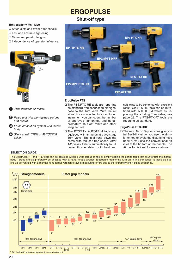
Bolt capacity M6 – M20❏ Safer joints and fewer after-checks.❏ Fast and accurate tightening.❏ Minimum operator fatigue.❏ Independence of operator influence.
ErgoPulse PTS❏ The PTS/PTX-RE tools are reporting
as standard. You connect an air signalhose to the Trim valve. With the airsignal hose connected to a monitoringinstrument you can count the numberof approved tightenings and detectpremature shut-off, rehits and otherirregularities.
❏ The PTS/PTX AUTOTRIM tools areequipped with an automatic two-stageTrim valve. The tool runs down thescrew with reduced free speed. After1-2 pulses it shifts automatically to fullpower thus enabling both hard and
Twin chamber air motor.
Pulse unit with cam-guided pistonsand rollers.
Patented shut-off system with inertiabody.
Silencer with TRIM or AUTOTRIMvalve.
Screw size
TorqueNm
3/8" square drive 1/2" square drive3/4" square
drive
soft joints to be tightened with excellentresult. Old PTS-RE tools can be retro-fitted with AUTOTRIM valves by re-placing the existing Trim valve, seepage 22. The PTS/PTX-AT tools arereporting as standard.
ErgoPulse PTS-HRF❏ The new Air on Top versions give you
full flexibility, either you use the air in-let on top to avoid the disturbing hosehook or you use the conventional airinlet at the bottom of the handle. TheAir on Top is ideal for work stations.
The ErgoPulse PT and PTS tools can be adjusted within a wide torque range by simply setting the spring force that counteracts the inertiabody. Torque should preferably be checked with a hand torque wrench. Electronic monitoring with an in-line transducer is possible butshould be verified with a manual hand torque wrench to avoid measuring errors due to the extremely short pulse sequence.
Straight models Pistol grip models
3/8" square drive

21
ERGOPULSEShut-off type
Dis- Air con- Recom-Square Recommended tance sumption mended Air
Bolt drive torque rangea Free Weight centre under load hose inlet Soundsize size speed Length to side size thread level
Model mm in Nm ft lb r/min kg lb mm mm l/s cfm mm in dB(A) Ordering No.
Straight models. ErgoPulse 5-8PTEP5PT SR42 M6 1/4b 5 - 10 4 - 7 5000c 0.9 1.9 212 21 6 13 8 1/4 74 8431 0368 02EP5PT SR10 M6 3/8 6 - 11 4 - 8 5000c 0.9 1.9 208 21 6 13 8 1/4 74 8431 0368 00EP6PT SR42 M6 1/4b 8 - 14 6 - 10 6000c 0.9 2.0 212 21 6 13 8 1/4 74 8431 0368 12EP6PT SR10 M6 3/8 9 - 15 7 - 11 6000c 0.9 2.0 208 21 6 13 8 1/4 74 8431 0368 08EP7PT SR42 M8 1/4b 12 - 23 9 - 17 4500c 1.2 2.5 240 25 7 15 8 1/4 78 8431 0368 37EP7PT SR10 M8 3/8 13 - 25 10 - 18 4500c 1.2 2.5 236 25 7 15 8 1/4 78 8431 0368 31EP8PT SR42 M8 1/4b 20 - 35 15 - 26 6000c 1.2 2.6 240 25 8 17 8 1/4 78 8431 0367 90EP8PT SR10 M8 3/8 22 - 40 16 - 29 6000c 1.2 2.6 236 25 8 17 8 1/4 78 8431 0367 80Pistol grip models. ErgoPulse 5-12PTEP5PT HR42 M6 1/4b 5 - 10 4 - 7 5500c 0.95 2.1 205 21 6 13 8 1/4 74 8431 0368 05EP5PT HR10 M6 3/8 6 - 11 4 - 8 5500c 0.95 2.1 200 21 6 13 8 1/4 74 8431 0368 04EP6PT HR42 M6 1/4b 8 - 14 6 - 10 6000c 1.0 2.2 205 21 6 13 8 1/4 74 8431 0368 23EP6PT HR10 M6 3/8 9 - 15 7 - 11 6000c 1.0 2.2 200 21 6 13 8 1/4 74 8431 0368 16EP7PT HR42 M8 1/4b 12 - 23 9 - 17 4500c 1.3 2.9 175 26 7 15 8 1/4 77 8431 0368 36EP7PT HR10 M8 3/8 13 - 25 10 - 18 4500c 1.3 2.9 177 26 7 15 8 1/4 77 8431 0368 30EP8PT HR42 M8 1/4b 20 - 35 15 - 26 6000c 1.4 3.0 175 26 8 17 8 1/4 77 8431 0367 94EP8PT HR10 M8 3/8 22 - 40 16 - 29 6000c 1.4 3.0 177 26 8 17 8 1/4 77 8431 0367 85EP10PT HR13 M10 1/2 32 - 70 24 - 51 4000c 1.8 4.0 192 29 10 21 10 1/4 81 8431 0367 66EP12PT HR13 M12 1/2 62 - 125 46 - 92 3500c 2.4 5.3 201 34 12 25 10 1/4 81 8431 0368 40
Pistol grip models. ErgoPulse 5-6PTSd
EP5PTS12 HR42-RE M5-M6 1/4b 6 - 12 4 - 9 5400c 1.0 2.2 196 21 6.5 14 8 1/4 74 8431 0374 05EP5PTS14 HR10-RE M5-M6 3/8 8 - 14 6 - 10 5400c 1.0 2.2 191 21 6.5 14 8 1/4 74 8431 0374 00EP6PTS20 HR42-RE M6 1/4b 8 - 20 6 - 15 7300c 1.0 2.2 196 21 7 15 8 1/4 74 8431 0374 15EP6PTS22 HR10-RE M6 3/8 10 - 22 7 - 16 7300c 1.0 2.2 191 21 7 15 8 1/4 74 8431 0374 20Pistol grip models. Balanced grip. ErgoPulse 5-18PTSd
EP7PTS30 HR42-RE M8 1/4b 16 - 31 12 - 23 5700c 1.4 3.0 175 26 8 17 10 1/4 77 8431 0374 35EP7PTS35 HR10-RE M8 3/8 18 - 35 13 - 26 5700c 1.4 3.0 176 26 8 17 10 1/4 77 8431 0374 40EP8PTS40 HR42-RE M8 1/4b 22 - 40 16 - 29 7300c 1.4 3.0 175 26 9 19 10 1/4 77 8431 0374 55EP8PTS55 HR10-RE M8-M10 3/8 30 - 55 22 - 40 7300c 1.4 3.0 176 26 9 19 10 1/4 77 8431 0374 60EP10PTS90 HR13-RE M10-M12 1/2 50 - 90 37 - 66 5200c 1.8 4.0 193 29 11 23 10 1/4 83 8431 0374 80EP12PTS150 HR13-RE M12-M14 1/2 85 - 150 63 - 110 4200c 2.5 5.5 201 34 13 27 13 3/8 83 8431 0374 90EP14PTS250 HR20-RE M12-M16 3/4 125 - 250 92 - 185 4000c 3.3 7.2 216 37 20 42 13 3/8 82 8431 0374 95EP18PTS450 HR20-RE M16-M20 3/4 225 - 450 166 - 332 3000c 4.3 9.5 202 42 22 46 13 3/8 85 8431 0374 98Pistol grip. Air on top models. ErgoPulse 7-10PTSEP7PTS35 HRF10-RE M8 3/8 18 - 35 13 - 26 5700c 1.4 3.0 176 31 8 17 10 1/4 77 8431 0374 41EP8PTS55 HRF10-RE M8-M10 3/8 30 - 55 22 - 40 7300c 1.4 3.0 176 31 9 19 10 1/4 77 8431 0374 61EP10PTS90 HRF13-RE M10-M12 1/2 50 - 90 37 - 66 5200c 1.8 4.0 193 34 11 23 10 1/4 81 8431 0374 81
Pistol grip models. ErgoPulse 6PTSEP6PTS20 HR42-AT M6 1/4b 8 - 20 6 - 15 3600e 1.0 2.2 196 21 7 15 8 1/4 74 8431 0374 16EP6PTS22 HR10-AT M6 3/8 10 - 22 7 - 16 3600e 1.0 2.2 191 21 7 15 8 1/4 74 8431 0374 21Pistol grip models. Balanced grip. ErgoPulse 5-18PTSd
EP7PTS30 HR42-AT M8 1/4b 16 - 31 12 - 23 3600e 1.4 3.0 175 26 8 17 10 1/4 77 8431 0374 37EP7PTS35 HR10-AT M8 3/8 18 - 35 13 - 26 3600e 1.4 3.0 176 26 8 17 10 1/4 77 8431 0374 42EP8PTS40 HR42-AT M8 1/4b 22 - 40 16 - 29 4000e 1.4 3.0 175 26 9 19 10 1/4 77 8431 0374 57EP8PTS55 HR10-AT M8-10 3/8 30 - 55 22 - 40 4000e 1.4 3.0 176 26 9 19 10 1/4 77 8431 0374 62EP10PTS90 HR13-AT M10-12 1/2 50 - 90 37 - 66 3400e 1.8 4.0 193 29 11 23 10 1/4 83 8431 0374 82EP12PTS150 HR13-AT M12-14 1/2 85 - 150 63 - 110 2800e 2.5 5.5 201 34 13 27 13 3/8 83 8431 0374 92EP14PTS250 HR20-AT M12-16 3/4 125 - 250 92 - 185 2200e 3.3 7.2 216 37 20 42 13 3/8 82 8431 0374 97EP18PTS450 HR20-AT M16-20 3/4 225 - 450 166 - 332 1900e 4.3 9.5 202 42 22 46 13 3/8 85 8431 0374 99Pistol grip. Air on top models. ErgoPulse 7-10PTSEP7PTS35 HRF10-AT M8 3/8 18 - 35 13 - 26 3600e 1.4 3.0 176 31 8 17 10 1/4 77 8431 0374 43EP8PTS55 HRF10-AT M8-10 3/8 30 - 55 22 - 40 4000e 1.4 3.0 176 31 9 19 10 1/4 77 8431 0374 63EP10PTS90 HRF13-AT M10-12 1/2 50 - 90 37 - 66 3400e 1.8 4.0 193 34 11 23 10 1/4 81 8431 0374 83
a To be used as a guide only, final torque depends on type of joint, accessories used and air pressure.b Female hexagon drive. Quick change chuck.c With TRIM valve fully open.d Approximate maximum torque included in designation.e In reduced speed mode.
TRIM-RE
AUTOTRIM
22
EP7PTX HR
EP5/6PTX HR
EP9PTX HR
AUTOTRIM valves for ErgoPulse PTS/PTX-RE
Model Ordering No.
EP5/6PTS/PTX 4250 1878 90EP7/8PTS/PTX 4250 1878 91EP10PTS/9PTX 4250 1878 92EP12PTS 4250 1878 93EP14PTS 4250 1878 94EP18PTS 4250 1878 95
ERGOPULSEShut-off type
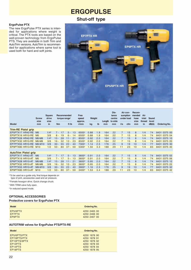
ErgoPulse PTXThe new ErgoPulse PTX series is inten-ded for applications where weight iscritical. The PTX tools are based on thewell-proven technology from ErgoPulsePTS. They are available in both Trim andAutoTrim versions. AutoTrim is recommen-ded for applications where same tool isused both for hard and soft joints.
Dis- Air con- Recom-Square Recommended Free tance sumption mended Air
Screw drive torque rangea speed Weight centre under load hose inlet Soundsize size approx. Length to side size thread level
Model mm in Nm ft lb r/min kg lb mm mm l/s cfm mm in dB(A) Ordering No.
Trim-RE Pistol gripEP5PTX17 HR42-RE M6 1/4b 7 - 17 5 - 13 6500c 0.88 1.9 164 22 7 15 8 1/4 74 8431 0375 00EP5PTX19 HR10-RE M6 3/8 8 - 19 6 - 14 6500c 0.88 1.9 164 22 7 15 8 1/4 74 8431 0375 04EP6PTX28 HR42-RE M6-M8 1/4b 15 - 28 11 - 21 8500c 0.92 2.0 164 22 7 15 8 1/4 74 8431 0375 10EP6PTX32 HR10-RE M6-M8 3/8 16 - 32 12 - 23 8500c 0.92 2.0 164 22 7 15 8 1/4 74 8431 0375 20EP7PTX55 HR10-RE M8-M10 3/8 30 - 55 22 - 40 7300c 1.14 2.5 176 25 9 19 10 1/4 77 8431 0375 30EP9PTX80 HR13-RE M10 1/2 50 - 80 37 - 59 5300c 1.50 3.3 188 29 11 23 10 1/4 83 8431 0375 40
AutoTrim Pistol gripEP5PTX17 HR42-AT M6 1/4b 7 - 17 5 - 13 3600d 0.91 2.0 164 22 7 15 8 1/4 74 8431 0375 02EP5PTX19 HR10-AT M6 3/8 7 - 17 5 - 13 3600d 0.91 2.0 164 22 7 15 8 1/4 74 8431 0375 06EP6PTX28 HR10-AT M6-M8 1/4b 15 - 28 11 - 21 3600d 0.95 2.0 164 22 7 15 8 1/4 74 8431 0375 12EP6PTX32 HR10-AT M6-M8 3/8 16 - 32 12 - 23 3600d 0.95 2.0 164 22 7 15 8 1/4 74 8431 0375 22EP7PTX55 HR10-AT M8-M10 3/8 30 - 55 22 - 40 3900d 1.16 2.5 176 25 9 19 10 1/4 77 8431 0375 32EP9PTX80 HR13-AT M10 1/2 50 - 80 37 - 59 3400d 1.53 3.4 188 29 11 23 10 1/4 83 8431 0375 42
OPTIONAL ACCESSORIESProtective covers for ErgoPulse PTX
Model Ordering No.
EP5/6PTX 4250 2465 00EP7PTX 4250 2466 00EP9PTX 4250 2467 00
a To be used as a guide only, final torque depends ontype of joint, accessories used and air pressure.
b Female hexagon drive. Quick change chuck.c With TRIM valve fully open.d In reduced speed mode.
23
EP10C HR
EP10XS HR
EP6C HRF
M20
M16M14
M12
M10
M8
M5
M6
M4
9
5
240
160
400
300
70
50
20
10*
16
9
16
8
52
30*
31
20*
4
2
8
4
8
13
10*
20
31
20*
52
30*
70
42
110
65
160
110
12
5
28
4C 5C 6XS6C 7XS 8XS 5CS5C 20XS16XS14XS10XS6XS6C 7XS 8XS 10C 12XS5XS 6PS
8.8
EP7XS HR
EP16XS HR
EP6XS SR
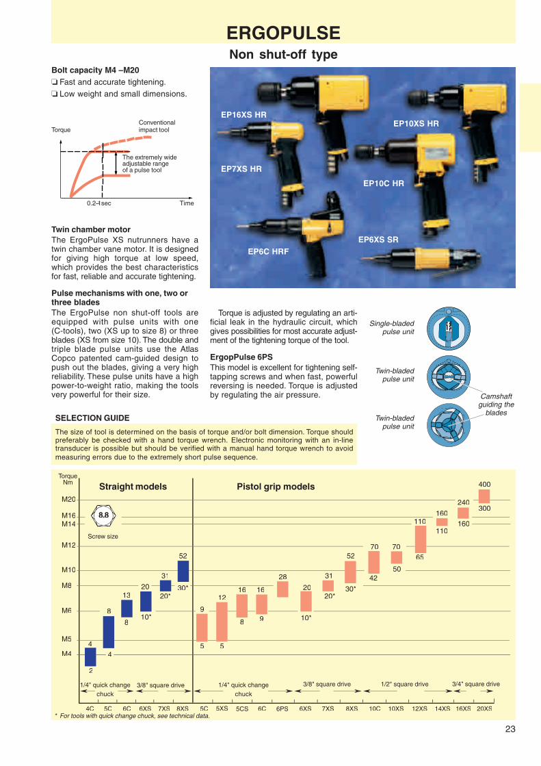
Bolt capacity M4 – M20❏ Fast and accurate tightening.❏ Low weight and small dimensions.
TorqueNm Straight models Pistol grip models
ConventionalTorque impact tool
The extremely wideadjustable rangeof a pulse tool
0.2–1sec Time
Twin chamber motorThe ErgoPulse XS nutrunners have atwin chamber vane motor. It is designedfor giving high torque at low speed,which provides the best characteristicsfor fast, reliable and accurate tightening.
Pulse mechanisms with one, two orthree bladesThe ErgoPulse non shut-off tools areequipped with pulse units with one(C-tools), two (XS up to size 8) or threeblades (XS from size 10). The double andtriple blade pulse units use the AtlasCopco patented cam-guided design topush out the blades, giving a very highreliability. These pulse units have a highpower-to-weight ratio, making the toolsvery powerful for their size.
SELECTION GUIDE
* For tools with quick change chuck, see technical data.
Screw size
The size of tool is determined on the basis of torque and/or bolt dimension. Torque shouldpreferably be checked with a hand torque wrench. Electronic monitoring with an in-linetransducer is possible but should be verified with a manual hand torque wrench to avoidmeasuring errors due to the extremely short pulse sequence.
Torque is adjusted by regulating an arti-ficial leak in the hydraulic circuit, whichgives possibilities for most accurate adjust-ment of the tightening torque of the tool.
ErgopPulse 6PSThis model is excellent for tightening self-tapping screws and when fast, powerfulreversing is needed. Torque is adjustedby regulating the air pressure.
Twin-bladedpulse unit
Twin-bladedpulse unit
Camshaftguiding the
blades
Single-bladedpulse unit
ERGOPULSENon shut-off type
3/8" square drive1/4" quick changechuck
1/4" quick changechuck
3/8" square drive 1/2" square drive 3/4" square drive

24
Dis- Air Recom-Square Recommended tance consumption mended Air
Bolt drive torque range a Free Weight centre under load hose inlet Soundsize size speed Length to side size thread levelb
Model mm in Nm ft lb r/min kg lb mm mm l/s cfm mm in dB(A) Ordering No.
Air on top modelsEP5C HRF42 M5 1/4c 5 - 9 4 - 7 4800 1.1 2.4 201 25 6 13 8 1/4 70 8431 0260 23EP6C HRF42 M6 1/4c 9 - 16 7 - 12 4800 1.2 2.6 226 25 6 13 8 1/4 70 8431 0260 30EP8X HRF42 M8 1/4c 18 - 30 13 - 22 9000 1.2 2.6 184 25 6 13 8 1/4 70 8431 0360 97EP8X HRF10 M8 3/8 20 - 35 15 - 26 9000 1.2 2.6 184 25 6 13 8 1/4 77 8431 0360 89
Straight modelsEP4C SR42 M4 1/4c 2 - 4 1 - 3 8200 0.8 1.8 255 19 2.5 5 6 1/4 70 8431 0350 02EP5C SR42 M5 1/4c 4 - 8 3 - 6 10500 0.9 2.0 238 20 5 10 8 1/4 72 8431 0261 14EP6C SR42 M6 1/4c 8 - 13 6 - 9 10500 1.0 2.2 263 20 5 10 8 1/4 72 8431 0261 22EP6XS SR42 M6 1/4c 9 - 19 6 - 14 8000 0.7 1.5 219 22 8 17 8 1/4 74 8431 0372 27EP6XS SR10 M6 3/8 10 - 20 7 - 15 8000 0.7 1.5 221 22 8 17 8 1/4 74 8431 0372 25EP7XS SR42 M8 1/4c 17 - 28 13 - 21 10000 0.7 1.5 219 22 8 17 8 1/4 74 8431 0372 15EP7XS SR10 M8 3/8 20 - 31 15 - 23 10000 0.7 1.5 221 22 8 17 8 1/4 74 8431 0372 05EP8XS SR42 M8 1/4c 22 - 40 16 - 29 8000 0.9 2.0 242 24 9 19 8 1/4 78 8431 0369 30EP8XS SR10 M8 3/8 30 - 52 22 - 38 8000 0.9 2.0 244 24 9 19 8 1/4 78 8431 0369 20
Pistol grip modelsEP5C HR42 M5 1/4c 5 - 9 4 - 7 4800 1.0 2.2 225 22 6 13 8 1/4 70 8431 0260 15EP5XS HR42 M5-M6 1/4c 5 - 12 4 - 9 8500 0.8 1.8 165 21 9 19 8 1/4 75 8431 0372 30EP5CS HR42 M5-M6 1/4c 8 - 16 6 - 12 4800 1.0 2.2 225 22 6 13 8 1/4 70 8431 0260 17EP6C HR42 M6 1/4c 9 - 16 7 - 12 4800 1.1 2.4 250 22 6 13 8 1/4 70 8431 0262 13EP6XS HR42 M6 1/4c 9 - 19 6 - 14 8000 0.8 1.8 150 22 8 17 8 1/4 75 8431 0372 23EP6XS HR10 M6 3/8 10 - 20 7 - 15 8000 0.8 1.8 152 22 8 17 8 1/4 75 8431 0372 20EP6PS HR42 M8 1/4c d - 28 d - 21 8000 0.8 1.8 148 21 9 19 10 1/4 74 8431 0368 22EP6PS HR10 M8 3/8 d - 30 d - 22 8000 0.8 1.8 150 21 9 19 10 1/4 74 8431 0368 21EP7XS HR42 M8 1/4c 17 - 28 13 - 21 9000 0.8 1.8 150 22 8 17 8 1/4 75 8431 0372 10EP7XS HR10 M8 3/8 20 - 31 15 - 23 9000 0.8 1.8 152 22 8 17 8 1/4 75 8431 0372 00EP8XS HRX42 M8 1/4c 22 - 40 16 - 29 7000 1.0 2.0 172 23 9 19 10 1/4 80 8431 0369 16EP8XS HRX10 M8 3/8 30 - 52 22 - 38 7000 1.0 2.0 174 23 9 19 10 1/4 80 8431 0369 09EP10C HR13 M10 1/2 42 - 70 31 - 52 7500 2.0 4.4 163 27 7 15 8 1/4 79 8431 0365 01EP10XS HR13 M10 1/2 50 - 70 37 - 52 6000 1.3 2.9 168 26 11 23 10 1/4 78 8431 0369 40EP12XS HR13 M12 1/2 65 - 110 48 - 81 4500 1.6 3.5 178 29 12 25 10 1/4 79 8431 0371 00EP14XS HR13 M14 1/2 110 - 160 81 - 118 3500 2.4 5.3 188 34 14 30 13 3/8 79 8431 0371 50EP16XS HR20 M16 3/4 160 - 240 118 - 177 2800 3.3 7.3 205 37 15 32 13 3/8 81 8431 0371 55EP20XS HR20 M20 3/4 300 - 400 221 - 295 3700 5.1 11.2 240 43 16 34 13 3/8 80 8431 0371 60
SELECTED SERVICE KITSThe spare parts included inthe service kits cover a normaloverhaul of your tool. Alwayshave them available for a fast
and economical repair.
Main parts included:❏ Vane kit ❏ O-rings❏ Motor bearings ❏ Circlips❏ Gaskets ❏ Pins etc.
Model O-ring kit pulse unit Service kit
EP5C/6C SR 4081 0110 90EP5C/6C HR 4081 0111 90EP10C HR 4081 0115 90EP5XS 4210 2532 93 4081 0264 90EP6/7XS HR 4250 2084 90 4081 0188 90EP6/7XS SR 4250 2084 90 4081 0189 90EP6PS HR 4250 2058 91 4081 0274 90EP8XS HRX 4250 2085 90 4081 0119 90EP8XS SR 4250 2085 90 4081 0190 90EP10XS HR 4250 2086 90 4081 0191 90EP12XS HR 4250 2087 90 4081 0192 90EP14XS HR 4250 2170 90 4081 0200 90EP16XS HR 4250 2281 90 4081 0223 90EP20XS HR 4250 2281 91 4081 0245 90
Model O-ring kit pulse unit Service kit
EP5/6PT HR 4250 2058 90 4081 0122 90EP5/6PT SR 4250 2058 90 4081 0123 90EP7/8PT HR 4250 2059 90 4081 0120 90EP7/8PT SR 4250 2059 90 4081 0198 90EP10PT HR 4250 2060 90 4081 0124 90EP12PT HR 4250 2061 90 4081 0125 90EP5/6PTS HR 4250 2058 90 4081 0122 90EP7/8PTS HR 4250 2267 91 4081 0225 90EP10PTS HR 4250 2267 90 4081 0222 90EP12PTS HR 4250 2267 92 4081 0226 90EP14PTS HR 4250 2267 93 4081 0242 90EP18PTS HR 4250 2267 94 4081 0256 90
ERGOPULSENon shut-off type
a To be used as a guide only, final torque depends on type of joint, accessories used and air pressure.b When exhaust hose is used.c Female hexagon drive. Quick change chuck.d Torque is adjusted by regulating the air pressure.
Oil filling kit (150 ml oil, syringe) 4081 0121 90For complete information, see spare parts list.

25
ACCESSORIES
DiameterSquare of outgoing
Available for drive spindle LengthErgoPulse models in mm mm Marking Ordering No.
6-8XS and 3/8 13 100 EP10-13-100 4023 3600 005-8PT/PTS/PTX 3/8 13 150 EP10-13-150 4023 3601 00
3/8 13 200 EP10-13-200 4023 3611 003/8 13 250 EP10-13-250 4023 3612 003/8 13 300 EP10-13-300 4023 3613 00
10C and 1/2 16 100 EP13-16-100 4023 3602 0010-12XS 1/2 16 150 EP13-16-150 4023 3603 00
1/2 16 200 EP13-16-200 4023 3604 001/2 16 250 EP13-16-250 4023 3614 001/2 16 300 EP13-16-300 4023 3615 00
14XS, 9PTX and 1/2 18 100 EP13-18-100 4023 3605 0010-12PT/PTS 1/2 18 150 EP13-18-150 4023 3606 00
1/2 18 200 EP13-18-200 4023 3607 001/2 18 250 EP13-18-250 4023 3616 001/2 18 300 EP13-18-300 4023 3617 00
16XS/20XS and 3/4 25 100 EP20-25-100 4023 3608 0014PTS/18PTS 3/4 25 150 EP20-25-150 4023 3609 00
3/4 25 200 EP20-25-200 4023 3610 003/4 25 250 EP20-25-250 4023 3618 003/4 25 300 EP20-25-300 4023 3619 00
Sockets
DiameterSquare Female of outgoing
Available for drive hex spindleErgoPulse models in in mm Marking Ordering No.
6-8XS and 3/8 1/4 13 EP3/8-1/4-13 4026 4501 005-8PT/PTS/PTX 3/8 7/16 13 EP3/8-7/16-13 4026 4502 00
10/14XS, 9PTX and 1/2 7/16 18 EP1/2-7/16-18 4026 4503 0010-12PT/PTS
Width DiameterSquare across of outgoing
Available for drive flats spindleErgoPulse models in mm/in mm Marking Ordering No.
Metric sockets6-8XS and 3/8 10 13 EP10-13 4026 4210 005-8PT/PTS/PTX 3/8 13 13 EP13-13 4026 4213 00
3/8 16 13 EP16-13 4026 4216 003/8 17 13 EP17-13 4026 4217 003/8 18 13 EP18-13 4026 4218 00
14XS, 9PTX and 1/2 13 18 EP13-18 4026 4313 0010-12PT/PTS 1/2 16 18 EP16-18 4026 4316 00
1/2 17 18 EP17-18 4026 4317 001/2 18 18 EP18-18 4026 4318 001/2 24 18 EP24-18 4026 4324 00
16XS/20XS and 3/4 18 25 EP18-25 4026 4418 0014PTS/18PTS 3/4 24 25 EP24-25 4026 4424 00
3/4 30 25 EP30-25 4026 4430 00
UNC/UNF-sockets6-8XS and 3/8 7/16 13 EP7/16-13 4026 4211 005-8PT/PTS/PTX 3/8 1/2 13 EP1/2-13 4026 4212 00
3/8 9/16 13 EP9/16-13 4026 4214 003/8 3/4 13 EP3/4-13 4026 4219 00
14XS, 9PTX and 1/2 1/2 18 EP1/2-18 4026 4312 0010-12PT/PTS 1/2 9/16 18 EP9/16-18 4026 4314 00
1/2 3/4 18 EP3/4-18 4026 4319 001/2 15/16 18 EP15/16-18 4026 4323 00
16XS/20XS and 3/4 3/4 25 EP3/4-25 4026 4419 0014PTS/18PTS 3/4 15/16 25 EP15/16-25 4026 4423 00
3/4 11/8 25 EP11/8-25 4026 4429 00
Quick change chuck for power tools
Extensions GUIDED SOCKETS AND EXTENSIONSSpecially designed for ErgoPulse nutrunners, AtlasCopco guided sockets and extensions provide deepengagement over the anvil bringing tool andattachment together as ”one unit”. They give quality,ergonomic and cost saving benefits.
❏ Improved torque transfer.❏ Improved accuracy.❏ Reduced vibration and noise levels.❏ Reduced operator fatigue.❏ Extends tool and attachment life.
OPTIONAL ACCESSORIES
Protective SupportPistol grip models cover handle
EP6/7XS HR 4250 2089 00EP8XS HRX 4250 1895 00EP10XS HR 4250 1784 00EP12XS HR 4250 2459 00EP14XS HR 4250 2160 00EP16XS HR 4250 2282 00EP20XS HR 4250 2288 00 IncludedEP5/6PT/PTS HR 4250 2393 00EP7/8PT/PTS HR 4250 1784 00EP10PT/PTS HR 4250 1743 00EP12PT/PTS HR 4250 1858 00EP14PTS HR 4250 2228 00 4250 2396 91EP18PTS HR 4250 2319 00 4250 2396 90
For complete information, see spare parts list.
26
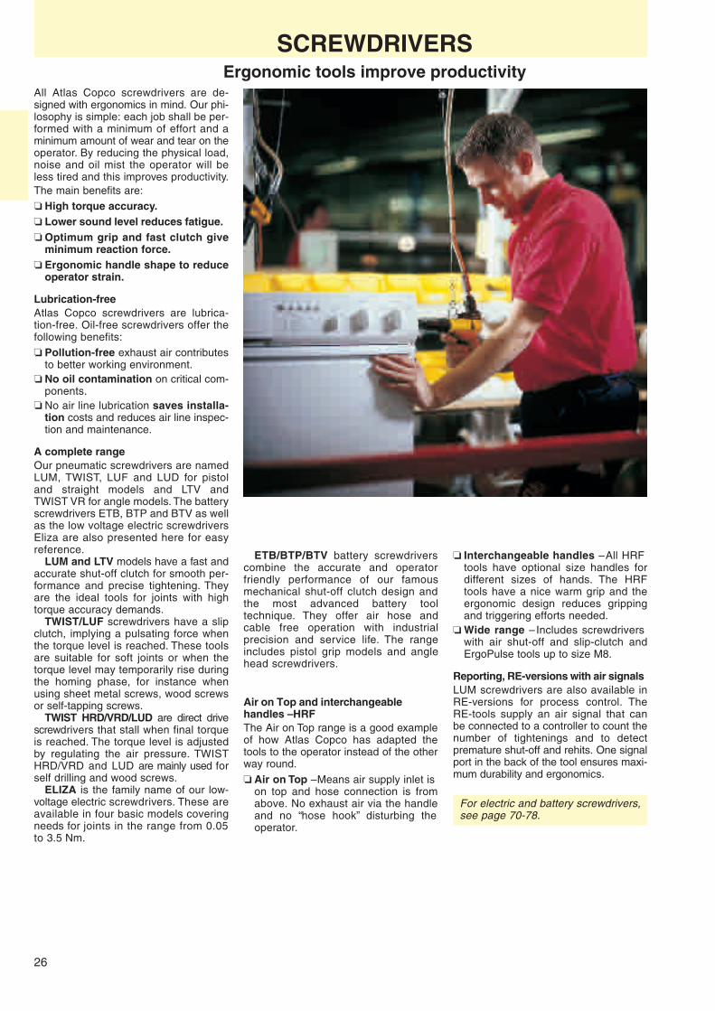
SCREWDRIVERSErgonomic tools improve productivity
All Atlas Copco screwdrivers are de-signed with ergonomics in mind. Our phi-losophy is simple: each job shall be per-formed with a minimum of effort and aminimum amount of wear and tear on theoperator. By reducing the physical load,noise and oil mist the operator will beless tired and this improves productivity.The main benefits are:❏ High torque accuracy.❏ Lower sound level reduces fatigue.❏ Optimum grip and fast clutch give
minimum reaction force.❏ Ergonomic handle shape to reduce
operator strain.
Lubrication-freeAtlas Copco screwdrivers are lubrica-tion-free. Oil-free screwdrivers offer thefollowing benefits:❏ Pollution-free exhaust air contributes
to better working environment.❏ No oil contamination on critical com-
ponents.❏ No air line lubrication saves installa-
tion costs and reduces air line inspec-tion and maintenance.
A complete rangeOur pneumatic screwdrivers are namedLUM, TWIST, LUF and LUD for pistoland straight models and LTV andTWIST VR for angle models. The batteryscrewdrivers ETB, BTP and BTV as wellas the low voltage electric screwdriversEliza are also presented here for easyreference.
LUM and LTV models have a fast andaccurate shut-off clutch for smooth per-formance and precise tightening. Theyare the ideal tools for joints with hightorque accuracy demands.
TWIST/LUF screwdrivers have a slipclutch, implying a pulsating force whenthe torque level is reached. These toolsare suitable for soft joints or when thetorque level may temporarily rise duringthe homing phase, for instance whenusing sheet metal screws, wood screwsor self-tapping screws.
TWIST HRD/VRD/LUD are direct drivescrewdrivers that stall when final torqueis reached. The torque level is adjustedby regulating the air pressure. TWISTHRD/VRD and LUD are mainly used forself drilling and wood screws.
ELIZA is the family name of our low-voltage electric screwdrivers. These areavailable in four basic models coveringneeds for joints in the range from 0.05to 3.5 Nm.
❏ Interchangeable handles – All HRFtools have optional size handles fordifferent sizes of hands. The HRFtools have a nice warm grip and theergonomic design reduces grippingand triggering efforts needed.
❏ Wide range – Includes screwdriverswith air shut-off and slip-clutch andErgoPulse tools up to size M8.
Reporting, RE-versions with air signalsLUM screwdrivers are also available inRE-versions for process control. TheRE-tools supply an air signal that canbe connected to a controller to count thenumber of tightenings and to detectpremature shut-off and rehits. One signalport in the back of the tool ensures maxi-mum durability and ergonomics.
For electric and battery screwdrivers,see page 70-78.
ETB/BTP/BTV battery screwdriverscombine the accurate and operatorfriendly performance of our famousmechanical shut-off clutch design andthe most advanced battery tooltechnique. They offer air hose andcable free operation with industrialprecision and service life. The rangeincludes pistol grip models and anglehead screwdrivers.
Air on Top and interchangeablehandles – HRFThe Air on Top range is a good exampleof how Atlas Copco has adapted thetools to the operator instead of the otherway round.❏ Air on Top – Means air supply inlet is
on top and hose connection is fromabove. No exhaust air via the handleand no “hose hook” disturbing theoperator.

27
M1.6 M2 M2.5 M3.5 M4 M6 M3 M5
ERGOPULSE
M1.6 M2 M2.5 M3.5 M4 M6 M3 M4.5 M5
ERGOPULSEM2 M4 M6 M5 M3
ST2.2 ST2.9 ST4.2ST3.5 ST4.8 ST5.5 ST6.3
ERGOPULSEST2.2 ST2.9 ST4.2ST3.5 ST4.8 ST5.5 ST6.3
ST2.2 ST2.9 ST4.2ST3.5 ST4.8 ST5.5 ST6.3
LUF20HRTWIST HRDTWIST HR16
TWIST HRD
TWIST HR08TWIST HR05
LUF34LUF34LUF34LUF34LUF34LUF34LUF34
LUF34LUF34LUF34LUF34LUF34LUF34LUF34
LUM12/13
BTP
LTV18
LTV008LTV08
LUM12/13
LTV18
LTV008LTV08
LUM12/13
LTV18
LTV008LTV08
ETB
ELIZA
LUM10
ETB
LUM21
LUM12/13
LTV18
LTV008LTV08
LUM25
ELIZALUM10
ETB
LUM21
LUM25
ELIZA
LUM10
LUM21
LUM SM
LUM25
LUM10
LUM21LUM25
ELIZA
LUF20
LUF34
TWIST
LUF10
LUM SM
BTP
BTP
SCREWDRIVERSSelection guide
0.09/0.8 0.2/1.8 0.4/3.5 0.6/5.3 1.0/8.8 1.4/12.4 2.9/25.7 4.9/43.4
0.2/1.8 0.4/3.5 0.7/6.2 1.2/10.6 1.9/16.8 2.9/25.7 4.3/38.1 5.7/50.4 9.8/86.7
1.4/12.40.5/4.4 11.0/97.37.373.2/28.3 6.5/57.57.57
0.3/2.7 1.8/15.9 2.9/25.7 4.2/37.27.27 6.7/59.3 9.1/80.51.0/8.8
0.3/2.7 1.8/15.9 2.9/25.7 4.2/37.27.27 6.7/59.3 9.1/80.51.0/8.8
1.5/13.3 3/26.5 7.5/66.4 12/106.25/44.2
0.3/2.7 1.8/15.9 2.9/25.7 4.2/37.27.27 6.7/59.3 9.1/80.51.0/8.8
SCREW TYPE SCREWDRIVERØ Screw size
Recommended tool
Machine screw 4.8Property class 4.8normal for crossrecessed andslotted screws
Machine screw 8.8Property class 8.8 normal for hexagon,Allen head and Torx . Locking nut withplastic insert, increasetorque 10%,mechanical-locknut, increasetorque 20%
Thread rolling screw-MProperty class between8.8 and 10.9 due tocase hardening.Taptite andSwageform areexamples
Thread forming screw-ST
Thread forming screw-STfor plastic
Self drilling screw-ST
Wood screw
With optional coupling-ring. Ordering No. 4210 2316 01
With optional spring. 4210 1831 00
Shut-off clutch ErgoPulse Slip clutch Direct drive
Torque Nm/in lb
Ø Screw size
Recommended tool
Torque Nm/in lb
Ø Screw size
Recommended tool
Torque Nm/in lb
Ø Screw size
Recommended tool
Torque Nm/in lb
Ø Screw size
Recommended tool
Torque Nm/in lb
Ø Screw size
Recommended tool
Torque Nm/in lb
Torque Nm/in lb Recommended tool

28
LUM12 HR
LUM25 HRX
LUM21 HR
LUM27 HRF
Torque range Air consumption Air DistanceScrew Soft joint Free at free speed Sound Weight inlet centre
Ø speed level Length thread to sideModel mm Nm in lb r/min l/s cfm dB(A) kg lb mm in mm Ordering No.
Pistol grip models with trigger startLUM12 HR02-U M2.2-M4 0.4 - 5 3.5 - 44 170 6 13 78 0.7 1.5 195 1/8 16.3 8431 0280 24LUM12 HR03-U M2.2-M4 0.4 - 5 3.5 - 44 370 6 13 78 0.6 1.4 185 1/8 16.3 8431 0280 20LUM12 HR03-U-RE M2.2-M4 0.4 - 5 3.5 - 44 370 6 13 78 0.6 1.4 185 1/8 16.3 8431 0280 21LUM12 HR09-U M2.2-M4 0.4 - 5 3.5 - 44 850 6 13 78 0.6 1.4 184 1/8 16.3 8431 0280 16*LUM12 HR09-U-RE M2.2-M4 0.4 - 5 3.5 - 44 850 6 13 78 0.6 1.4 184 1/8 16.3 8431 0280 17LUM12 HR12-U M2.2-M4 0.4 - 3.6 3.5 - 31 1100 6 13 78 0.6 1.4 184 1/8 16.3 8431 0280 15*LUM12 HR12-U-RE M2.2-M4 0.4 - 3.6 3.5 - 31 1100 6 13 78 0.6 1.4 184 1/8 16.3 8431 0280 14LUM12 HR17-U M2.5-M3.5 0.6 - 2.5 5.3 - 22 1600 6 13 78 0.6 1.4 174 1/8 16.3 8431 0280 12LUM12 HR17-U-RE M2.5-M3.5 0.6 - 2.5 5.3 - 22 1600 6 13 78 0.6 1.4 174 1/8 16.3 8431 0280 13LUM12 HR23-U M2.5-M3.5 0.6 - 1.8 5.3 - 16 2200 6 13 78 0.6 1.4 174 1/8 16.3 8431 0280 10LUM12 HR23-U-RE M2.5-M3.5 0.6 - 1.8 5.3 - 16 2200 6 13 78 0.6 0.9 174 1/8 16.3 8431 0280 11LUM13 HR05-U M3-M5 1 - 8 8.8 - 70 500 6 13 78 0.7 1.5 184 1/8 16.3 8431 0280 18LUM13 HR05-U-RE M3-M5 1 - 8 8.8 - 70 500 6 13 78 0.7 1.5 184 1/8 16.3 8431 0280 19LUM21 HR05-U M2.5-M5 0.5 - 4.5 4.4 - 40 480 7 15 78 0.9 2.0 219 1/4 23 8431 0267 58LUM21 HR08-U M2.5-M5 0.5 - 4.5 4.4 - 40 800 7 15 75 0.9 2.0 219 1/4 23 8431 0267 60*LUM21 HR08-U-RE M2.5-M5 0.5 - 4.5 4.4 - 40 800 7 15 75 0.9 2.0 219 1/4 23 8431 0264 80LUM21 HR12-U M2.5-M4 0.5 - 3.5 4.4 - 31 1200 4-6 8 76 0.8 1.8 209 1/4 23 8431 0267 64*LUM21 HR15-U M2.5-M4 0.5 - 3.5 4.4 - 31 1600 7 15 76 0.8 1.8 209 1/4 23 8431 0267 68LUM21 HR15-U-RE M2.5-M4 0.5 - 3.5 4.4 - 31 1500 7 15 76 0.8 1.8 209 1/4 23 8431 0264 82LUM21 HR23-U M2.5-M4 0.5 - 2.5 4.4 - 22 2300 7 15 76 0.8 1.8 209 1/4 23 8431 0267 70LUM25 HR01-U M4-M6a 3.5b - 12.5c 25 - 120b 100 7 15 78 1.1 2.4 260 1/4 23 8431 0264 50LUM25 HR03-U M4-M6 3.5b - 12.5c 25 - 110b 390 7 15 78 1.1 2.4 250 1/4 23 8431 0264 45LUM25 HR05-U M2.5-M6 3.5b - 12.0c 25 - 110b 480 7 15 78 1.1 2.4 250 1/4 23 8431 0264 03*LUM25 HR05-U-RE M2.5-M6 3.5b - 12.0c 25 - 110b 500 7 15 78 1.1 2.4 250 1/4 23 8431 0264 84LUM25 HR08-U M2.5-M6 3.5b - 7.5c 25 - 66b 800 7 15 75 1.1 2.4 250 1/4 23 8431 0264 11*LUM25 HR08-U-RE M2.5-M6 3.5b - 7.5c 25 - 66b 800 7 15 75 1.1 2.4 250 1/4 23 8431 0264 88LUM25 HR11-U M4-M5 3.5b - 5.5 25 - 49 1100 6 13 75 1.1 2.4 226 1/4 23 8431 0264 16
SCREWDRIVERSAir shut-off control – Pistol grip models
Screw size M2.2 – M6Torque range 0.4 – 12.5 Nm❏ More reliable joints – The LUM shut-off
mechanism means accurate tightening,time after time, independent of varia-tions in joint stiffness.
❏ Low reaction force – Rapid clutchwith air shut-off reduces the reactionforce on the wrist.
❏ Low sound levels – The housing withpatented silencer gives a low soundlevel.
❏ Operator comfort – Thanks to theergonomic designed pistol grip. Highgrip when high feeding force is needed,i.e., cross recess screws. Low grip forminimum reaction force.
❏ Lubrication-free. Oil free exhaust.Easy installation.
❏ Air on Top – Means air supply inlet ison top and hose connection is fromabove. No exhaust air via the handleand no hose hook disturbing the op-erator. As Air on Top tools are easier tomanoeuvre than traditional suspendedtools, they are ideal for work stations.
❏ The new LUM12/13 HR series offersan amazingly compact and light tooland yet possesses power and speedcomparable to many screwdrivers ofdouble the size. Still accuracy anddurability are of common Atlas Copcostandard which means quality jointsover an extended time of operation.
❏ RE-reporting – All LUM pistol typescrewdrivers are also available inreporting, -RE versions for processcontrol. Kits are also available for localconversion of standard models. Clutch deactivated Clutch activated Clutch release/shut-off
LUM SM – for sheet metal screwsWhen tightening screws in sheet metalyou might need a high torque to pro-duce the threads in the metal and lowfinal torque. LUM SM runs the screwdown at maximum torque with the clutchdeactivated. Towards the end of the
tightening the shut-off clutch is auto-matically activated. The clutch then re-leases at the desired torque. The frontnose is modified to fit different applica-tions and screw types.
Continued . . .

29
a Support handle included.b 1.4-4 Nm with spring Ordering No. 4210 1831 00.c For operator comfort support handle recommended for high torque, see Optional Accessories.d Front end, 11 mm (4210 3918 00), included.e Front end, 12.5 mm (4210 3918 01), included.f Optional front end, 21 mm (4210 3918 02).
Recommended hose size mm: LUM12/13/21 = 6, LUM25 = 8, LUM27 = 10
All models: Are reversible – Have quick change chuck.All data at an air pressure of 6.3 bar.
ACCESSORIES INCLUDEDPage 36
OPTIONAL ACCESSORIESPage 36
SELECTED SERVICE KITSPage 36
SCREWDRIVERSAir shut-off control – Pistol grip models
Air Dis-Torque range consumption at Air tance
Screw Soft joint Free free speed Sound Weight inlet centreØ speed level Length thread to side
Model mm Nm in lb r/min l/s cfm dB(A) kg lb mm in mm Ordering No.
Pistol grip models with trigger and push startLUM21 HR05 M2.5-M5 0.5 - 4.5 4.4 - 40 480 7 15 78 0.9 2.0 222 1/4 23 8431 0267 38*LUM21 HR08 M2.5-M5 0.5 - 4.5 4.4 - 40 800 7 15 75 0.9 2.0 222 1/4 23 8431 0267 40*LUM21 HR12 M2.5-M4 0.5 - 3.5 4.4 - 31 1200 4-6 8 76 0.8 1.8 212 1/4 23 8431 0267 44*LUM21 HR15 M2.5-M4 0.5 - 3.5 4.4 - 31 1600 7 15 76 0.8 1.8 212 1/4 23 8431 0267 48LUM21 HR23 M2.5-M4 0.5 - 2.5 4.4 - 22 2300 7 15 76 0.8 1.8 212 1/4 23 8431 0267 50LUM25 HR03 M4-M6 3.5b -12.5c 25 - 110 390 7 15 78 1.1 2.4 250 1/4 23 8431 0249 33LUM25 HR05 M4-M6 3.5b -12.0c 25 - 110 480 7 15 78 1.1 2.4 250 1/4 23 8431 0249 44*LUM25 HR08 M4-M6 3.5b - 7.5c 25 - 66 800 7 15 75 1.1 2.4 250 1/4 23 8431 0249 55*LUM25 HR11 M4-M5 3.5b - 5.5 25 - 49 1100 6 13 75 1.1 2.4 226 1/4 23 8431 0249 56
Balanced grip models with trigger startLUM21 HRX03-U M2.5-M5 0.5 - 4.5 4.4 - 40 370 7 15 75 0.9 2.0 180 1/4 20 8431 0263 59LUM21 HRX08-U M2.5-M5 0.5 - 4.5 4.4 - 40 800 7 15 75 0.9 2.0 180 1/4 20 8431 0263 54LUM21 HRX08-U-RE M2.5-M5 0.5 - 4.5 4.4 - 40 800 7 15 75 0.9 2.0 180 1/4 20 8431 0264 62LUM21 HRX15-U M2.5-M4 0.5 - 3.5 4.4 - 31 1600 7 15 76 0.8 1.8 170 1/4 20 8431 0263 56LUM21 HRX15-U-RE M2.5-M4 0.5 - 3.5 4.4 - 31 1600 7 15 76 0.8 1.8 170 1/4 20 8431 0264 60LUM25 HRX03-U M4-M6 3.5 -12.5b 31 - 120 390 7 15 77 1.2 2.6 209 1/4 20 8431 0263 79LUM25 HRX05-U M4-M6 3.5 -12.0b 31 - 110 480 7 15 77 1.2 2.6 209 1/4 20 8431 0263 70*LUM25 HRX05-U-RE M4-M6 3.5 -12.0b 31 - 110 500 7 15 77 1.2 2.6 209 1/4 20 8431 0264 64LUM25 HRX08-U M4-M6 3.5 - 7.5b 31 - 66 800 7 15 75 1.2 2.6 209 1/4 20 8431 0263 72*LUM25 HRX08-U-RE M4-M6 3.5 - 7.5b 31 - 66 800 7 15 75 1.2 2.6 209 1/4 20 8431 0264 66LUM27 HRX08-U M6 3.5 - 9.5 31 - 88 750 9 19 79 1.2 2.6 217 1/4 20 8431 0263 83*LUM27 HRX08-U-RE M6 3.5 - 9.5 31 - 88 750 9 19 79 1.2 2.6 217 1/4 20 8431 0264 68LUM27 HRX11-U M4-M6 3.5 - 7.0 31 - 62 1030 9 19 79 1.2 2.6 217 1/4 20 8431 0263 85*
Air-on-top models with trigger startLUM21 HRF03-U M2.5-M5 0.5 - 4.5 4.4 - 40 370 7 15 71 1.1 2.4 197 1/4 25 8431 0267 99LUM21 HRF05-U M2.5-M5 0.5 - 4.5 4.4 - 40 480 7 15 71 1.1 2.4 197 1/4 25 8431 0267 92LUM21 HRF08-U M2.5-M5 0.5 - 4.5 4.4 - 40 800 7 15 71 1.1 2.4 197 1/4 25 8431 0267 94*LUM21 HRF08-U-RE M2.5-M5 0.5 - 4.5 4.4 - 40 800 7 15 71 1.1 2.4 197 1/4 25 8431 0264 90LUM21 HRF15-U M2.5-M4 0.5 - 3.5 4.4 - 31 1600 7 15 71 1.1 2.4 187 1/4 25 8431 0267 96*LUM21 HRF15-U-RE M2.5-M4 0.5 - 3.5 4.4 - 31 1600 7 15 71 1.1 2.4 187 1/4 25 8431 0264 92LUM21 HRF23-U M2.5-M4 0.5 - 2.5 4.4 - 22 2100 7 15 71 1.1 2.4 187 1/4 25 8431 0267 98LUM25 HRF05-U M4-M6 3.5 -12.0b 31 - 110 500 6 13 73 1.2 2.6 226 1/4 26 8431 0249 05*LUM25 HRF05-U-RE M4-M6 3.5 -12.0b 31 - 110 500 6 13 73 1.2 2.6 226 1/4 26 8431 0264 96LUM25 HRF08-U M4-M5 3.5 - 7.5b 31 - 66 800 6 13 73 1.2 2.6 226 1/4 26 8431 0249 07*LUM25 HRF08-U-RE M4-M5 3.5 - 7.5b 31 - 66 800 6 13 73 1.2 2.6 226 1/4 26 8431 0264 98LUM25 HRF11-U M4-M5 3.5 - 5.5b 31 - 49 1100 6 13 73 1.2 2.6 226 1/4 26 8431 0249 09
Sheet metal screwdrivers with trigger startLUM21 HR08-SMdf M2.5-M5 0.5 - 4.5 4.4 - 40 800 7 15 78 0.9 2.0 255 1/4 23 8431 0267 51*LUM21 HR15-SMef M2.5-M4 0.5 - 3.5 4.4 - 31 1600 7 15 76 0.8 1.8 245 1/4 23 8431 0267 53*
* Basic tools of the range, cover most needs.
OPTIONAL ACCESSORIESHRF modelsSwivel, hose dia 8 mm 4210 3134 80
Handle small size 4210 3139 00
Support handle 4110 1355 86
Hose reel balancer, HRIL 4 8202 0600 29

30
LUM25 PR
LUM10 PR
LUM21 SR
LUM12 PR
SCREWDRIVERSAir shut-off control – Straight models
Screw size M1.6 – M6Torque range 0.1 – 11 Nm❏ Safer joints – The LUM shut-off
mechanism means accurate tighten-ing, time after time, independently ofvariations in joint stiffness.
❏ Rapid clutch with air shut-off reducesthe reaction force on the wrist.
❏ Low sound levels – Thanks to nonresonating plastics on LUM10/21, pat-ented silencer and exhaust hose.
❏ Operator comfort – Correct grip dia-meter means minimum reaction forceand less operator fatigue. Optimal gripfor women is 34 mm and for men 38mm. Atlas Copco offers grip diameterbetween 30 and 40 mm.
❏ Lubrication-free – Means clean en-vironment, no units to refill or maintainand quicker set-up.
❏ The new LUM12 offers a lightweighttool with amazingly high speed andcapacity for its size. The tool comes inpush and lever start versions.
❏ RE-reporting – All LUM straight screw-drivers with lever start can be suppliedin reporting, -RE, versions or can beconverted locally. (See page 36 forconversion kits).
ERGOPUSHThe ergonomic grip for assemblyapplications where axial force isneeded.All assembly operations require a certainaxial force to enter the screw. In mostcases the axial force needed is quitelow but in some cases a higher force isneeded. The axial force depends on thetype of screw and screw head that willbe used. A self tapping or self drillingscrew needs a higher axial force to en-gage than a machine screw and a Philipshead requires a higher axial force thana Torx® head.
The Ergopush grip is the ideal so-lution where higher axial force is needed.Available as an option for the followingstraight Atlas Copco screwdrivers.
Model Ordering No.
LUM21 PR/SR 4210 3842 00
LUM25 PR/SR14 4210 3808 00
LUM25 PR/SR18 4210 3808 00
OPTIONAL ACCESSORIESClutch housing metal for LUM21 SR/PR forfixtured applications.Ordering No. 4210 2933 82

31
Recommended hose size mm: LUM10/12/13/21 = 6,LUM25 = 8, LUM37 = 10
All models: Are reversible – Have quick changechuck.SR-models have ring reverse control.PR-models have push button reverse.
a 1.4-4 Nm with spring Ordering No. 4210 1831 00.b Front end 12.5 mm (4210 3918 01) included.c Optional front end 21 mm (4210 3918 02).d See page 28 for more information about SM models.e ESD approved.
ACCESSORIES INCLUDEDPage 36
OPTIONAL ACCESSORIESPage 36
Air con- DistanceTorque range sumption Air centre
Screw Soft joint Free at free speed Sound Weight inlet toØ speed level Length thread side
Model mm Nm in lb r/min l/s cfm dB(A) kg lb mm in mm Ordering No.
Straight models with push start and button reverseLUM10 PR03e M1.6-M4 0.1 - 1.5 0.8 - 13 300 3 6 66 0.4 0.9 206 1/8 15 8431 0146 05*LUM10 PR05e M1.6-M4 0.1 - 1.5 0.8 - 13 460 3 6 66 0.4 0.9 206 1/8 15 8431 0146 09*LUM10 PR12e M1.6-M3 0.1 - 1.1 0.8 - 10 1200 3 6 66 0.4 0.9 196 1/8 15 8431 0146 17*LUM10 PR21e M1.6-M2.5 0.1 - 0.7 0.8 - 6 2000 3 6 67 0.4 0.9 196 1/8 15 8431 0146 25LUM12 PR20-Pe M2.2-M3 0.6 - 1.6 5.3 - 14 1900 6 13 78 0.4 0.9 185 1/8 16 8431 0280 50LUM12 PR15-Pe M2.2-M3.5 0.4 - 2.2 3.5 - 19 1400 6 13 78 0.4 0.9 185 1/8 16 8431 0280 52LUM12 PR10-Pe M2.2-M4 0.4 - 3.2 3.5 - 28 1000 6 13 78 0.4 0.9 195 1/8 16 8431 0280 54*LUM12 PR07-Pe M2.5-M4 0.5 - 4.2 3.5 - 37 700 6 13 78 0.4 0.9 185 1/8 16 8431 0280 56LUM21 PR04-P M2.5-M5 0.5 - 4.5 4.4 - 40 320 4 8 70 0.7 1.5 239 1/8 18 8431 0277 02LUM21 PR07-P M2.5-M5 0.5 - 4.5 4.4 - 40 700 4 8 70 0.7 1.5 239 1/8 18 8431 0277 00*LUM21 PR10-P M2.5-M5 0.5 - 3.2 4.4 - 30 1000 4 8 71 0.7 1.5 239 1/8 18 8431 0277 08*LUM21 PR14-P M2.5-M4 0.5 - 2.4 4.4 - 21 1400 4 8 71 0.7 1.5 239 1/8 18 8431 0277 14*LUM21 PR23-P M2.5-M3 0.5 - 1.5 4.4 - 13 2200 4 8 69 0.7 1.5 239 1/8 18 8431 0277 20LUM25 PR05-P M4-M6 3.5 -11.0a 30 - 97 430 6 13 70 1.0 2.2 242 1/4 19 8431 0265 41*LUM25 PR07-P M4-M5 3.5 - 7.0a 30 - 62 700 6 13 70 1.0 2.2 242 1/4 19 8431 0265 43*LUM25 PR10-P M4 3.5 - 5.5a 30 - 49 1000 6 13 71 1.0 2.2 242 1/4 19 8431 0265 46LUM25 PR14-P M2.5-M4 0.6 - 3.5 5.3 - 31 1400 6 13 71 1.0 2.2 205 1/4 19 8431 0265 49*LUM25 PR18-P M2.5-M4 0.6 - 3.2 5.3 - 28 1800 6 13 71 1.0 2.2 205 1/4 19 8431 0265 52Straight models with lever start and without push startLUM12 SR20-Ue M2.5-M3 0.6 - 1.8 5.3 - 16 2100 6 13 78 0.4 0.9 185 1/8 16 8431 0280 58LUM12 SR17-Ue M2.5-M3.5 0.5 - 2.5 3.5 - 22 1700 6 13 78 0.4 0.9 185 1/8 16 8431 0280 60LUM12 SR11-Ue M2.5-M4 0.5 - 3.5 3.5 - 31 1100 6 13 78 0.4 0.9 195 1/8 16 8431 0280 62*LUM12 SR07-Ue M2.2-M4 0.4 - 4.5 3.5 - 40 800 6 13 78 0.4 0.9 195 1/8 16 8431 0280 64LUM21 SR04-Ue M2.5-M5 0.5 - 4.5 4.4 - 40 320 4 8 70 0.7 1.5 240 1/8 18 8431 0277 22LUM21 SR07-Ue M2.5-M5 0.5 - 4.5 4.4 - 40 700 4 8 70 0.7 1.5 240 1/8 18 8431 0277 24*LUM21 SR07-U-REe M2.5-M5 0.5 - 4.5 4.4 - 40 700 4 8 70 0.7 1.5 240 1/8 18 8431 0264 70LUM21 SR10-Ue M2.5-M5 0.5 - 3.2 4.4 - 30 1000 4 8 71 0.7 1.5 240 1/8 18 8431 0277 28*LUM21 SR10-U-REe M2.5-M5 0.5 - 3.2 4.4 - 30 1000 4 8 71 0.7 1.5 240 1/8 18 8431 0264 72LUM21 SR14-Ue M2.5-M4 0.5 - 2.4 4.4 - 21 1400 4 8 71 0.7 1.5 240 1/8 18 8431 0277 30LUM21 SR23-Ue M2.5-M4 0.5 - 1.5 4.4 - 13 2200 4 8 71 0.7 1.5 240 1/8 18 8431 0277 34LUM25 SR05-U M4-M6 3.5 -11.0a 25 - 97a 430 6 13 71 1.1 2.4 266 1/4 19 8431 0264 29*LUM25 SR05-U-RE M4-M6 3.5 -11.0a 25 - 97a 430 6 13 71 1.1 2.4 266 1/4 19 8431 0264 74LUM25 SR07-U M4-M5 3.5 - 7.0a 25 - 62a 700 6 13 71 1.1 2.4 266 1/4 19 8431 0264 37*LUM25 SR07-U-RE M4-M5 3.5 - 7.0a 25 - 62a 700 6 13 71 1.1 2.4 266 1/4 19 8431 0264 76LUM25 SR10-U M4 3.5 - 5.5a 25 - 49a 1000 6 13 71 1.1 2.4 266 1/4 19 8431 0264 39LUM25 SR14-U M2.5-M4 0.6 - 3.5 5.3 - 31 1400 6 13 71 1.0 2.2 229 1/4 19 8431 0264 41LUM25 SR18-U M2.5-M4 0.6 - 3.2 5.3 - 28 1800 6 13 71 1.0 2.2 229 1/4 19 8431 0264 43LUM37 SR36-U M3-M5 1.5 - 4.5 13.3 - 40 3500 16 34 80 1.5 3.3 317 1/4 20 8431 0266 20LUM37 SR25-U M4-M6 5.0 - 7.5 44.2 - 66 2500 16 34 80 1.6 3.5 338 1/4 20 8431 0266 15Sheet metal screwdrivers with lever startLUM21 SR07-U-SMbcd M2.5-M5 0.5 - 4.5 4.4 - 40 700 6 13 71 1.1 2.4 229 1/4 19 8431 0264 56LUM25 SR07-U-SMbcd M4-M5 3.5 - 7.0 31 - 62 700 6 13 71 1.1 2.4 317 1/4 20 8431 0264 52LUM25 SR05-U-SMbcd M4-M6 3.5 -11.0 31 - 97 450 6 13 71 1.1 2.4 338 1/4 20 8431 0264 54
SELECTED SERVICE KITSPage 36
SCREWDRIVERSAir shut-off control – Straight models
START OPTIONS
Reverse optionsStraight screwdrivers with leverthrottle have a ring for reverseoperation. All push start modelsare equipped with push buttonfor frequent and fast reversing.
Push startCommon for straight tools onassembly lines. The tool startswhen you push the bit towardsthe screw. Minimizes tighteningtime. Pistol grip tools with push-start have the combined func-tion push and trigger start.
Lever startRecommended when a proper engage-ment between bit and screw head and/orscrew and workpiece is essential beforestarting the operation.
* Basic tools of the range, cover most needs.

32
LTV18 R07-6
LTV008 R07-6
TWIST VR07-I6
LTV18 R15-42
SCREWDRIVERSAngle head models
Screw size M2.2 – M6Torque range 0.4 – 15 Nm❏ Good accessibility – The small size,
slim design angle head provides forexcellent access in limited spacesand awkward positions. Note, new ex-tremely slim and low head.
❏ Safer joints – The rapid mechanismin shut-off models means accuratetightening, time after time, indepen-dent of variations in joint stiffness.
❏ High capacity – Despite the small size,the angle screwdrivers have a highcapacity and wearing properties tomatch the highest demands in indus-trial line production. Note, the newsmall size angle head up to 15 Nm.
❏ Less operator fatigue – The balanceand the slim lines contribute to theergonomic design and make the toolsconvenient to work with for maximumoperator performance.
❏ Lubrication-free. Oil free exhaust.Easy installation.
❏ The new LTV008 angle head screw-drivers, designed with focus on access-ibility, ease of handling and highestproductivity without sacrificing accuracyin tightening. The result is a series ofscrewdrivers with unmatched perfor-mance for its size. Contributing to thisare a slim design, an exceptionallycompact angle head and a small andlightweight clutch design.
❏ RE-reporting – Connection ports forreporting signal, -RE, are easily ar-ranged on the angle screwdrivers witha conversion kit available as optionalequipment (see page 36).
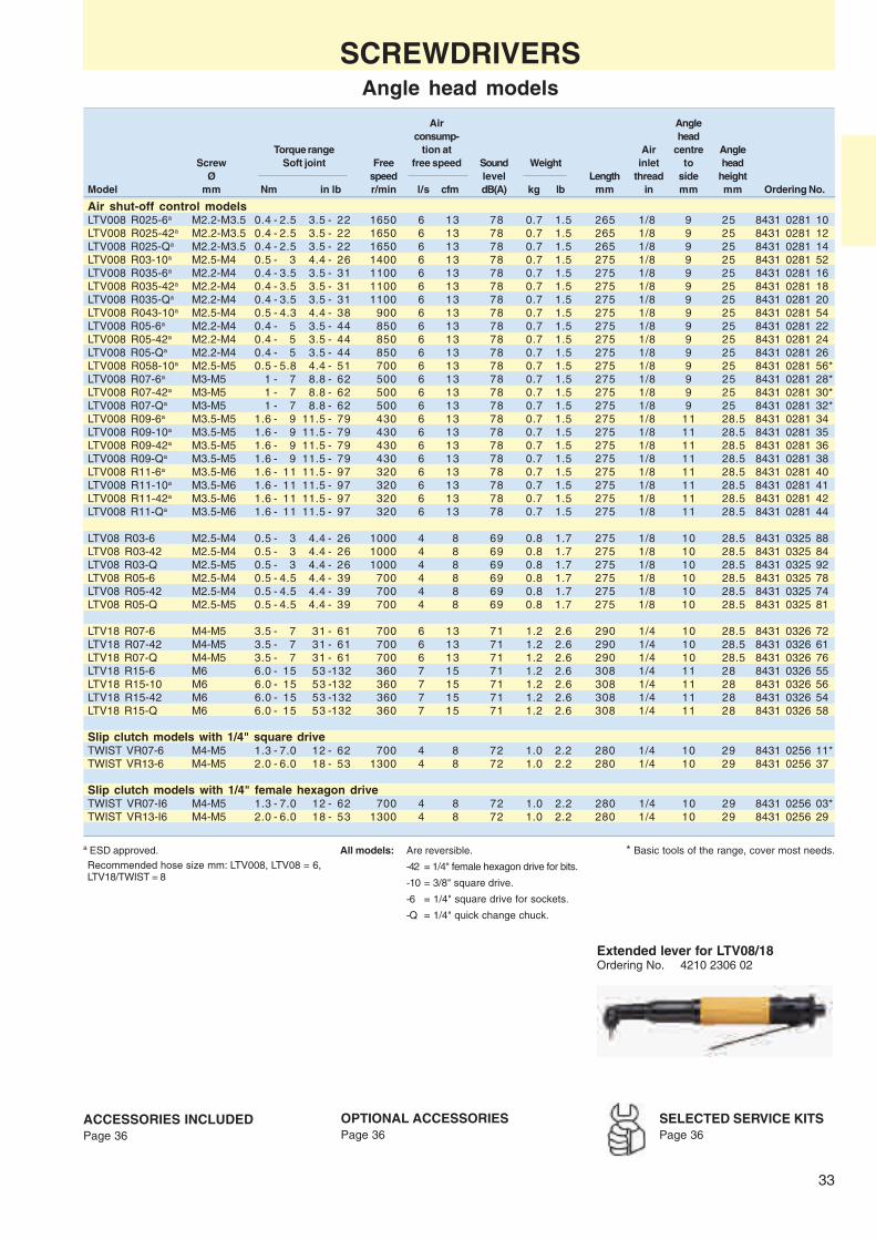
33
Air Angleconsump- head
Torque range tion at Air centre AngleScrew Soft joint Free free speed Sound Weight inlet to head
Ø speed level Length thread side heightModel mm Nm in lb r/min l/s cfm dB(A) kg lb mm in mm mm Ordering No.
Air shut-off control modelsLTV008 R025-6a M2.2-M3.5 0.4 - 2.5 3.5 - 22 1650 6 13 78 0.7 1.5 265 1/8 9 25 8431 0281 10LTV008 R025-42a M2.2-M3.5 0.4 - 2.5 3.5 - 22 1650 6 13 78 0.7 1.5 265 1/8 9 25 8431 0281 12LTV008 R025-Qa M2.2-M3.5 0.4 - 2.5 3.5 - 22 1650 6 13 78 0.7 1.5 265 1/8 9 25 8431 0281 14LTV008 R03-10a M2.5-M4 0.5 - 3 4.4 - 26 1400 6 13 78 0.7 1.5 275 1/8 9 25 8431 0281 52LTV008 R035-6a M2.2-M4 0.4 - 3.5 3.5 - 31 1100 6 13 78 0.7 1.5 275 1/8 9 25 8431 0281 16LTV008 R035-42a M2.2-M4 0.4 - 3.5 3.5 - 31 1100 6 13 78 0.7 1.5 275 1/8 9 25 8431 0281 18LTV008 R035-Qa M2.2-M4 0.4 - 3.5 3.5 - 31 1100 6 13 78 0.7 1.5 275 1/8 9 25 8431 0281 20LTV008 R043-10a M2.5-M4 0.5 - 4.3 4.4 - 38 900 6 13 78 0.7 1.5 275 1/8 9 25 8431 0281 54LTV008 R05-6a M2.2-M4 0.4 - 5 3.5 - 44 850 6 13 78 0.7 1.5 275 1/8 9 25 8431 0281 22LTV008 R05-42a M2.2-M4 0.4 - 5 3.5 - 44 850 6 13 78 0.7 1.5 275 1/8 9 25 8431 0281 24LTV008 R05-Qa M2.2-M4 0.4 - 5 3.5 - 44 850 6 13 78 0.7 1.5 275 1/8 9 25 8431 0281 26LTV008 R058-10a M2.5-M5 0.5 - 5.8 4.4 - 51 700 6 13 78 0.7 1.5 275 1/8 9 25 8431 0281 56*LTV008 R07-6a M3-M5 1 - 7 8.8 - 62 500 6 13 78 0.7 1.5 275 1/8 9 25 8431 0281 28*LTV008 R07-42a M3-M5 1 - 7 8.8 - 62 500 6 13 78 0.7 1.5 275 1/8 9 25 8431 0281 30*LTV008 R07-Qa M3-M5 1 - 7 8.8 - 62 500 6 13 78 0.7 1.5 275 1/8 9 25 8431 0281 32*LTV008 R09-6a M3.5-M5 1.6 - 9 11.5 - 79 430 6 13 78 0.7 1.5 275 1/8 11 28.5 8431 0281 34LTV008 R09-10a M3.5-M5 1.6 - 9 11.5 - 79 430 6 13 78 0.7 1.5 275 1/8 11 28.5 8431 0281 35LTV008 R09-42a M3.5-M5 1.6 - 9 11.5 - 79 430 6 13 78 0.7 1.5 275 1/8 11 28.5 8431 0281 36LTV008 R09-Qa M3.5-M5 1.6 - 9 11.5 - 79 430 6 13 78 0.7 1.5 275 1/8 11 28.5 8431 0281 38LTV008 R11-6a M3.5-M6 1.6 - 11 11.5 - 97 320 6 13 78 0.7 1.5 275 1/8 11 28.5 8431 0281 40LTV008 R11-10a M3.5-M6 1.6 - 11 11.5 - 97 320 6 13 78 0.7 1.5 275 1/8 11 28.5 8431 0281 41LTV008 R11-42a M3.5-M6 1.6 - 11 11.5 - 97 320 6 13 78 0.7 1.5 275 1/8 11 28.5 8431 0281 42LTV008 R11-Qa M3.5-M6 1.6 - 11 11.5 - 97 320 6 13 78 0.7 1.5 275 1/8 11 28.5 8431 0281 44
LTV08 R03-6 M2.5-M4 0.5 - 3 4.4 - 26 1000 4 8 69 0.8 1.7 275 1/8 10 28.5 8431 0325 88LTV08 R03-42 M2.5-M4 0.5 - 3 4.4 - 26 1000 4 8 69 0.8 1.7 275 1/8 10 28.5 8431 0325 84LTV08 R03-Q M2.5-M5 0.5 - 3 4.4 - 26 1000 4 8 69 0.8 1.7 275 1/8 10 28.5 8431 0325 92LTV08 R05-6 M2.5-M4 0.5 - 4.5 4.4 - 39 700 4 8 69 0.8 1.7 275 1/8 10 28.5 8431 0325 78LTV08 R05-42 M2.5-M4 0.5 - 4.5 4.4 - 39 700 4 8 69 0.8 1.7 275 1/8 10 28.5 8431 0325 74LTV08 R05-Q M2.5-M5 0.5 - 4.5 4.4 - 39 700 4 8 69 0.8 1.7 275 1/8 10 28.5 8431 0325 81
LTV18 R07-6 M4-M5 3.5 - 7 31 - 61 700 6 13 71 1.2 2.6 290 1/4 10 28.5 8431 0326 72LTV18 R07-42 M4-M5 3.5 - 7 31 - 61 700 6 13 71 1.2 2.6 290 1/4 10 28.5 8431 0326 61LTV18 R07-Q M4-M5 3.5 - 7 31 - 61 700 6 13 71 1.2 2.6 290 1/4 10 28.5 8431 0326 76LTV18 R15-6 M6 6.0 - 15 53 -132 360 7 15 71 1.2 2.6 308 1/4 11 28 8431 0326 55LTV18 R15-10 M6 6.0 - 15 53 -132 360 7 15 71 1.2 2.6 308 1/4 11 28 8431 0326 56LTV18 R15-42 M6 6.0 - 15 53 -132 360 7 15 71 1.2 2.6 308 1/4 11 28 8431 0326 54LTV18 R15-Q M6 6.0 - 15 53 -132 360 7 15 71 1.2 2.6 308 1/4 11 28 8431 0326 58
Slip clutch models with 1/4" square driveTWIST VR07-6 M4-M5 1.3 - 7.0 12 - 62 700 4 8 72 1.0 2.2 280 1/4 10 29 8431 0256 11*TWIST VR13-6 M4-M5 2.0 - 6.0 18 - 53 1300 4 8 72 1.0 2.2 280 1/4 10 29 8431 0256 37
Slip clutch models with 1/4" female hexagon driveTWIST VR07-I6 M4-M5 1.3 - 7.0 12 - 62 700 4 8 72 1.0 2.2 280 1/4 10 29 8431 0256 03*TWIST VR13-I6 M4-M5 2.0 - 6.0 18 - 53 1300 4 8 72 1.0 2.2 280 1/4 10 29 8431 0256 29
All models: Are reversible.
-42 = 1/4" female hexagon drive for bits.
-10 = 3/8" square drive.
-6 = 1/4" square drive for sockets.
-Q = 1/4" quick change chuck.
ACCESSORIES INCLUDEDPage 36
OPTIONAL ACCESSORIESPage 36
SCREWDRIVERSAngle head models
Extended lever for LTV08/18Ordering No. 4210 2306 02
a ESD approved.Recommended hose size mm: LTV008, LTV08 = 6,LTV18/TWIST = 8
SELECTED SERVICE KITSPage 36
* Basic tools of the range, cover most needs.

34
TWIST SR
LUF34 HR
TWIST HR
SCREWDRIVERSSlip-clutch
Screw size M1.6 – M6Torque range 0.1 – 17 NmThe slip clutch is the most suitablealternative for sheet metal screws.❏ Flexible – All models are reversible
and designed for both left and righthand operations.
❏ Fast tightening – Fast rundown andtightening by the high speed/high torquecombination.
❏ Operator comfort – Thanks to theergonomic design of the pistol grip.High grip when high feeding force isneeded, i.e., cross recess screws. Uselow grip for minimum twisting force.
❏ Lubrication-free – Oil free exhaust.Easy installation.
Air DistanceTorque range consumption at Air centre
Screw Soft joint Free free speed Sound Weight inlet toØ speed level Length thread side
Model mm Nm in lb r/min l/s cfm dB(A) kg lb mm in mm Ordering No.
Straight models with push startLUF10 PR12 M1.6-M3.5 0.1 - 1.0 0.9 - 9 1200 3 6 66 0.4 0.9 196 1/8 15 8431 0136 33LUF10 PR21 M1.6-M3.5 0.1 - 1.2 0.9 - 11 2100 3 6 67 0.4 0.9 196 1/8 15 8431 0136 41LUF20 PR14 M2.5-M4 1.0 - 2.0 8.8 - 18 1400 4 8 64 0.5 1.2 213 1/8 18 8431 0258 84
Straight models with lever startLUF20 SR14 M2.5-M4 1.0 - 2.0 8.8 - 18 1400 4 8 71 0.7 1.5 240 1/8 18 8431 0258 43TWIST12 SR11 M2.5-M4 0.5 - 4.2 4 - 37 1000 6 13 78 0.4 0.9 195 1/8 16 8431 0280 90TWIST12 SR17 M2.5-M4 0.7 - 3.3 6.2 - 30 1450 6 13 78 0.4 0.9 185 1/8 16 8431 0280 92TWIST SR07 M4-M5 1.3 - 7.0 12 - 62 700 4 8 76 0.9 2.0 260 1/4 19 8431 0252 15*TWIST SR13 M4-M5 2.0 - 6.0 18 - 53 1300 4 8 72 0.9 2.0 260 1/4 19 8431 0252 23*TWIST SR20 M4 2.2 - 4.5 20 - 40 2000 7 15 70 0.9 2.0 250 1/4 19 8431 0252 31*
Pistol grip models with trigger and push startTWIST12 HR09 M2.5-M4 0.5 - 4.4 4 - 40 750 6 13 78 0.6 1.3 185 1/8 16.3 8431 0280 70TWIST12 HR12 M2.5-M4 0.6 - 3.5 5 - 31 1000 6 13 78 0.6 1.3 185 1/8 16.3 8431 0280 72TWIST12 HR17 M2.5-M3.5 0.6 - 2.4 5 - 21 1450 6 13 78 0.6 1.3 175 1/8 16.3 8431 0280 74TWIST HR05 M5-M6 5.0 -12.0 44 - 106 500 7 15 78 1.1 2.4 245 1/4 20 8431 0252 56*TWIST HR08 M4-M5 1.5 - 7.5 13 - 66 800 7 15 75 1.1 2.4 245 1/4 20 8431 0252 64*TWIST HR11 M4-M5 1.5 - 7.5 13 - 66 1200 7 15 75 1.0 2.4 245 1/4 20 8431 0252 60*TWIST HR16 M4-M5 2.2 - 6.5 20 - 58 1600 7 15 76 1.0 2.2 245 1/4 20 8431 0252 72*TWIST HR23 M4-(M5) 2.4 - 5.0 21 - 44 2200 7 15 76 1.0 2.2 235 1/4 20 8431 0252 80*LUF34 HR04 M4-M6 3.0 -17.0 27 - 150 440 9.5 19 79 1.4 3.1 265 1/4 21 8431 0311 05LUF34 HR08 M4-M6 2.0 -15.0 18 - 133 750 9.5 19 79 1.4 3.1 265 1/4 21 8431 0311 09*LUF34 HR16 M4-M6 3.0 -12.0 27 - 107 1600 9.5 19 79 1.4 3.1 265 1/4 21 8431 0311 17
Pistol grip models with trigger and without push startLUF20 HR16-U M2.5-M4 0.5 - 1.9 4.4 - 17 1600 3.4 7 76 0.8 1.8 212 1/8 23 8431 0259 59LUF20 HR23-U M3-M4 0.6 - 2.5 5.3 - 22 2300 6.4 14 76 0.8 1.8 212 1/8 23 8431 0259 42
HRX models with trigger start and push startTWIST HRX08 M4-M5 1.5 - 7.5 13 - 68 800 7 15 75 1.1 2.4 196 1/4 20 8431 0263 26TWIST HRX16 M4-M5 2.2 - 6.5 20 - 68 1600 7 15 76 1.1 2.4 196 1/4 20 8431 0263 28*
Air on Top models with trigger start and push startTWIST HRF08 M4-M5 1.5 - 7.5 13 - 66 800 7 15 74 1.2 2.6 212 1/4 25 8431 0252 42TWIST HRF16 M4-M5 2.2 - 6.5 20 - 58 1600 7 15 74 1.2 2.6 212 1/4 25 8431 0252 44*
Recommended hose size mm: LUF10/14/20 = 6, LUF34 = 10, TWIST = 8
ACCESSORIES INCLUDEDPage 36
OPTIONAL ACCESSORIESPage 36
SELECTED SERVICE KITSPage 36
All models: Are reversible.Female hexagon drive for bits: 1/4".Have quick change chuck except LUF14.
Non push start washer for TWIST SR/HR 4210 2760 03.
* Basic tools of the range, cover most needs.

35
LUF34 HRD
TWIST HRD
LUD12 HR
SCREWDRIVERSDirect drive
Screw size M3 – M8Torque range 1.1 – 18 Nm❏ Suitable for sheet metal, self tapping
and wood screws.❏ Flexible – All models are reversible
and designed for both left and righthand operations.
❏ Combination tools – COMBI modelsincluding drill chuck, can be used forscrewdriving, drilling and tapping.
❏ Good accessibility – The short lengthon the pistol models gives very goodaccessibility. The angle types providegood access in limited spaces andawkward positions.
❏ Lubrication-free – Oil free exhaust.Easy installation.
a Torque at min 2 and max 6.3 bar.
Recommended hose size mm: TWIST/LUD12/COMBI24 = 8, LUF34/COMBI34 = 10
All models: Are reversible.Female hexagon drive for bits: 1/4" on pistol grip models.Combi-tools are delivered with drill chuck and 1/4" female hex drive for bits.Torque at min 3 bar and max 6 bar.
* Basic tools of the range, cover most needs.
ACCESSORIES INCLUDEDPage 36
OPTIONAL ACCESSORIESPage 36
SELECTED SERVICE KITSPage 36
Dis- AngleAir con- tance head
Torque range sumption at Air centre centre AngleScrew Soft joint Free free speed Sound Weight inlet to to head
Ø speed level Length thread side side heightModel mm Nm in lb r/min l/s cfm dB(A) kg lb mm in mm mm mm Ordering No.
Pistol grip models with trigger startTWIST HRD08 M6 5.0-10.0 44- 89 800 7 15 75 1.0 2.2 225 1/4 20 – – 8431 0255 20*TWIST HRD16 M4-M5 2.7- 5.7 24- 50 1600 7 15 76 0.8 1.7 195 1/4 20 – – 8431 0255 12TWIST HRD36 M3.5 2.0- 2.7 18- 24 3600 7 15 76 0.8 1.7 195 1/4 20 – – 8431 0255 04LUD12 HR05a M5 3.8- 8.5 29- 75 500 6 13 78 0.5 1.1 125 1/8 16.3 – – 8431 0281 04*LUD12 HR09a M3.5-M4 1.8- 5.7 16- 50 900 6 13 78 0.5 1.1 125 1/8 16.3 – – 8431 0281 06*LUD12 HR17a M3-M3.5 1.1- 2.9 10- 26 1700 6 13 78 0.5 1.1 115 1/8 16.3 – – 8431 0281 08
Pistol grip models with trigger start. Direct driveLUF34 HRD04 M6-M8 8.0-18.0 71-160 440 9 19 79 1.2 2.6 212 1/4 20 – – 8431 0311 22*LUF34 HRD08 M6 8.0-11.0 71- 97 750 9 19 79 1.2 2.6 212 1/4 20 – – 8431 0311 24LUF34 HRD16 M5-M6 4.0- 8.0 35- 71 1600 9 19 79 0.9 2.0 179 1/4 20 – – 8431 0311 26LUF34 HRD21 M4-M6 2.2- 4.5 20- 40 2000 9 19 79 0.9 2.0 179 1/4 20 – – 8431 0311 28
Reversible drill, tapper and screwdriverCOMBI24 HR08 M6 5.0-10.0 44- 89 800 7 15 75 1.1 2.4 240 1/4 20 – – 8431 0255 61COMBI24 HR16 M4-M5 2.7- 5.7 24- 50 1600 7 15 75 0.9 2.0 205 1/4 20 – – 8431 0255 79COMBI24 HR36 M3.5 2.0- 2.7 18- 24 3600 7 15 75 0.9 2.0 205 1/4 20 – – 8431 0255 88COMBI34 HR04 M6-M8 8.0-18.0 71-160 400 9 19 79 1.5 3.3 228 1/4 20 – – 8431 0311 32COMBI34 HR08 M6 8.0-11.0 71- 97 750 9 19 79 1.3 2.9 218 1/4 20 – – 8431 0311 34COMBI34 HR16 M5-M6 4.0- 8.0 35- 71 1600 9 19 79 1.0 2.2 179 1/4 20 – – 8431 0311 36
Angle head models with 1/4" square driveTWIST VRD07-6 M4-M5 1.6- 6.0 14- 53 700 4 9 72 1.0 2.2 280 1/4 – 10 29 8 431 0256 78TWIST VRD13-6 M4-M5 2.5- 5.0 22- 44 1300 4 9 72 1.0 2.2 280 1/4 – 10 29 8431 0256 94
Angle head models with 1/4" female hexagon driveTWIST VRD07-I6 M4-M5 1.6- 6.0 14- 53 700 4 9 72 1.0 2.2 280 1/4 – 10 29 8431 0256 60TWIST VRD13-I6 M4-M5 2.5- 5.0 22- 44 1300 4 9 72 1.0 2.2 280 1/4 – 10 29 8431 0256 86TWIST VRD20-I6 M4-M5 2.7- 4.0 24- 35 2000 7 15 74 1.0 2.2 270 1/4 – 10 29 8431 0257 02

36
ACCESSORIES
ACCESSORIES INCLUDED
Clutch adjustmentkeyIncluded for all shut-offand slip clutch tools
Quick change chuckIncluded on all straight andpistol grip tools exceptLUF14
Suspension yokeIncluded for all straightand pistol grip tools
Exhaust hoseIncluded for straightand air-on-top models
Hose nippleIncluded for all tools
SELECTED SERVICE KITSThe spare parts included inthe service kits cover a
normal overhaul of your tool. Alwayshave them available for a fast andeconomical repair.Main parts included:❏ Vane kit❏ Motor bearings❏ Gaskets❏ O-rings❏ Circlips❏ Pins etc.
OPTIONAL ACCESSORIES
Lever start assembly kit, Front part for slotted screws ReversingDesignation Exhaust hose only PR models Support handle bit finders see page 116 knob extended ESD-hose
LUM/LUF10 – 4210 2067 80 – 4210 2906 80 – 8202 0501 06LUM21/LUF20 HR – – – 4210 2906 80 4210 3204 90 8202 0501 06LUM21 PR/SR – 4210 2067 80 4210 2054 81 4210 2906 80 –LUM25 PR – 4210 2061 80 4210 2054 80 – –LUM25 HR 4210 2052 00 – 4110 1355 86 4210 2906 80 4210 3204 90LUM25 PR/SR – 4210 2061 80 4210 2054 80 4210 2906 80 –
TWIST SR 4210 2053 00 – 4210 2054 80 4210 2323 90 –TWIST VR/VRD 4210 2053 00 – – – –TWIST HR 4210 2053 00 – 4210 2054 80 4210 2323 90 4210 3204 90TWIST HRD 4210 2053 00 – 4210 2054 80 – 4210 3204 90
LUF34 HR – – 4110 1355 82a – 4210 3204 91LUF34 HRD – – 4110 1355 82a – 4210 3204 91
Non push start washer for TWIST SR/HR 4210 2760 03Coupling ring for TWIST, 0.5-2 Nm 4210 2316 01
a Standard for LUF34 HR/HRD04.
Angle head for LTV008, LTV08, LTV18 and TWIST VR/VRD
Quick change chuck set 90o hex drive 90o hex drive 30o hex drive MagneticDesignation for power bits magnetic bitholder magnetic bitholder magnetic bitholder 30o hex drive bitholder set
LTV008 – 4210 3857 91 – – – –LTV08/18 4210 2934 83 – 4110 1404 89 4110 1436 81 4110 1436 80 4210 2367 91TWIST VR/VRD 4210 2934 83 – – – – 4210 2367 91
Kits for screwdriversModel Ordering No.
LUM10 PR 4081 0070 90LUM21 PR 4081 0071 90LUM21 SR-U 4081 0072 90LUM21 HR/HRF 4081 0076 90LUM25 HR 4081 0077 90LUM25 SR-U 4081 0073 90LUM25 PR 4081 0074 90LUM25 HRF 4081 0075 90TWIST HR/HRF 4081 0079 90TWIST SR/VR 4081 0078 90TWIST HRD 4081 0082 90LUF20 SR 4081 0083 90LTV08 SR 4081 0084 90LTV18 SR 4081 0085 90LUF34 HR 4081 0086 90
Quick change chuck kitExtra wide diameter for easyhandling 4210 2326 91
a Please note: the RE-conversion kit is not recom-mended for use with LUM12 PR.
Model Ordering No.
LUM21/25 HR 4210 1927 50LUM21 SR 4210 2912 92LUM25 SR 4210 3067 92LUM12 SRa 4210 4137 90LUM12 HR 4210 4032 81LUM HRX 4210 3617 91LTV008 4210 4137 90LTV08 4210 4022 90LTV18 4210 4023 90
RE-Conversion kits for LUM/LTVmodels

37
NUTRUNNERSPower, speed, accuracy and complete easy handleness
An unbeatable combination of power,speed and accuracy are the main criteriasfor Atlas Copco´s range of nutrunners.
Those criterias make the Atlas Copconutrunners a unique choice:❏ Power – A high power output in relation
to weight and dimension is decisive forproductivity, i.e. the combined perfor-mance of operator and tool.
❏ Speed – Atlas Copco nutrunners havespeed optimised for every torque ca-pacity rating.
❏ Accuracy – The constantly high acc-uracy, a matter of balance betweenspeed and clutch response, decidestorque repeatability independently ofjoint characteristics.
❏ Ergonomics – The low weight, ther-mally insulated grip and low noise andvibration levels are all factors that helpto reduce operator fatigue. This raisesindividual performance and contributesto higher overall productivity in yourplant.
❏ Complete easy handleness – Simpli-city in selection and installation allowsyou to set the torque once and that isthe torque you will get, joint after joint,without complicated analyses.
It is easy to choose the right tool – nojoint is complicated for a nutrunner. To setthe torque – just adjust it to the requiredlevel, regardless of joint conditions.
Our wide range of nutrunners consistsof the three main categories:– Angle nutrunners– Straight nutrunners– Pistol grip nutrunners
These versions are also available inoptional models such as torque moni-tored, crowfoot, Hold and Drive, Flushsocket etc.
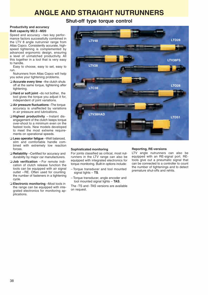
38
LTV48
LTO28
LTV28
LTC38
LTV38FS
LTV38HAD
LTD28
LTD51
ANGLE AND STRAIGHT NUTRUNNERSShut-off type torque control
Productivity and accuracyBolt capacity M2.5 – M20Speed and accuracy – two key perfor-mance factors successfully combined inthe LTV 8 angle nutrunner range fromAtlas Copco. Consistently accurate, high-speed tightening is complemented byadvanced ergonomic design, ensuringa level of unmatched productivity. Allthis together in a tool that is very easyto handle.
Easy to choose, easy to set, easy torun.
Nutrunners from Atlas Copco will helpyou solve your tightening problems.❏ Accurate every time – the clutch shuts
off at the same torque, tightening aftertightening.
❏ Hard or soft joint – do not bother, thetool gives the torque you adjust it for,independent of joint variations.
❏ Air pressure fluctuations – The torqueaccuracy is unaffected by variationsin air pressure and lubrications.
❏ Highest productivity – Instant dis-engagement of the clutch keeps torqueover-shoot to a minimum even on thefastest tools. New models developedto meet the most extreme require-ments on operational speeds.
❏ Less operator fatigue – Well balanced,slim and comfortable handle com-bined with extremely low reactionforces.
❏ Reliability – Certified for accuracy anddurability by major car manufacturers.
❏ Job verification – For remote indi-cation of clutch release function thetools can be equipped with air signaloutlet – RE. Often used for countingthe number of fasteners in a tighteningcycle.
❏ Electronic monitoring – Most tools inthe range can be equipped with inte-grated electronics for monitoring ap-plications.
Sophisticated monitoringFor joints classified as critical, most nut-runners in the LTV range can also beequipped with integrated electronics fortorque monitoring. Built-in options include:
– Torque transducer and tool mountedsignal lights – TS.
– Torque transducer, angle encoder andtool mounted signal lights – TAS.
The -TS and -TAS versions are availableon request.
Reporting, RE-versionsLTV angle nutrunners can also beequipped with an RE-signal port. RE-tools give out a pneumatic signal thatcan be connected to a controller to countthe number of tightenings and to detectpremature shut-offs and rehits.

39
LTV28
LTV18
LTV08
ANGLE NUTRUNNERSShut-off type torque control
The LTV 8 seriesBolt capacity M2.5 – M22❏ Accurate – The consistent clutch dis-
engagement is your guarantee for aminimum of torque scatter.
❏ Low mean shift – The adjustablemechanism in the shut-off clutch is notaffected by variations in joint rate or airpressure.
❏ Extremely fast – The unique clutchdesign allows you to select high speedmodels without compromising accuracy.
❏ Ergonomic and safe – Most of thereaction is taken up by the inertia ofthe tool thanks to the rapid clutch shut-off.
❏ Serviceability – The tools are built tolast but are at the same time design-ed for easy, effective service and main-tenance.
❏ Accessible and convenient – Qua-lities offered by the lean and smoothexterior in combination with small sizeangle head and perfect balance. Newsmall size angle head up to 15 Nm.
Distance Recom- Aircentre men- consump-
Suitable Square Torque range to side Angle ded tion atfor bolt drive Soft joint Free Weight angle head hose free speed Sound
size size speed Length head height size levelModel mm in Nm ft lb r/min kg lb mm mm mm mm l/s cfm dB(A) Ordering No.
Torque control LTV. Reversible modelsLTV08 R03-6 M2.5-M4 1/4 0.5 - 3 0.4- 2.2 1000 0.8 1.7 275 10 28.5 6.3 4 8 69 8431 0325 88LTV08 R03-42 M2.5-M4 1/4a 0.5 - 3 0.4- 2.2 1000 0.8 1.7 275 10 28.5 6.3 4 8 69 8431 0325 84LTV08 R03-Q M2.5-M5 1/4b 0.5 - 3 0.4- 2.2 1000 0.8 1.7 275 10 28.5 6.3 4 8 69 8431 0325 92LTV08 R05-6 M2.5-M4 1/4 0.5 - 4.5 0.4- 3.3 700 0.8 1.7 275 10 28.5 6.3 4 8 69 8431 0325 78LTV08 R05-42 M2.5-M4 1/4a 0.5 - 4.5 0.4- 3.3 700 0.8 1.7 275 10 28.5 6.3 4 8 69 8431 0325 74LTV08 R05-Q M2.5-M5 1/4b 0.5 - 4.5 0.4- 3.3 700 0.8 1.7 275 10 28.5 6.3 4 8 69 8431 0325 81LTV18 R07-6 M4-M5 1/4 3.5 - 7 2.6- 5 700 1.2 2.6 290 10 28.5 8 6 13 71 8431 0326 72LTV18 R07-42 M4-M5 1/4a 3.5 - 7 2.6- 5 700 1.2 2.6 290 10 28.5 8 6 13 71 8431 0326 61LTV18 R07-Q M4-M5 1/4b 3.5 - 7 2.6- 5 700 1.2 2.6 290 10 28.5 8 6 13 71 8431 0326 76LTV18 R15-6 M6 1/4 6 - 15 4- 11 360 1.2 2.6 308 11 28 8 6 13 71 8431 0326 55LTV18 R15-10 M6 3/8 6 - 15 4- 11 360 1.2 2.6 308 11 28 8 6 13 71 8431 0326 56LTV18 R15-42 M6 1/4a 6 - 15 4- 11 360 1.2 2.6 308 11 28 8 6 13 71 8431 0326 54LTV18 R15-Q M6 1/4b 6 - 15 4- 11 360 1.2 2.6 308 11 28 8 6 13 71 8431 0326 58LTV28 R07-6 M5 1/4 2.5 - 7 1.8- 5 1100 1.3 2.9 334 10 28.5 8 8 17 76 8431 0601 65LTV28 R07-42 M5 1/4a 2.5 - 7 1.8- 5 1100 1.3 2.9 334 10 28.5 8 8 17 76 8431 0601 73LTV28 R07-Q M6 1/4b 2.5 - 7 1.8- 5 1100 1.3 2.9 334 10 28.5 8 8 17 76 8431 0601 68LTV28 R15-6 M6 1/4 7 - 15 5- 11 560 1.4 3.1 349 11 28 10 10 21 76 8431 0601 52LTV28 R15-42 M6 1/4a 7 - 15 5- 11 560 1.4 3.1 349 11 28 10 10 21 76 8431 0601 58LTV28 R15-Q M6 1/4b 7 - 15 5- 11 560 1.4 3.1 349 11 28 10 10 21 76 8431 0601 53LTV28 R15-10 M6 3/8 7 - 15 5- 11 560 1.4 3.1 349 11 28 10 10 21 76 8431 0601 55LTV28 R20-10 M6 3/8 10 - 19 7- 15 530 1.4 3.1 355 13.5 34.5 10 10 21 76 8431 0601 50LTV28 R20-42 M6 1/4a 10 - 20 7- 15 420 1.4 3.1 350 13.5 34 10 10 21 76 8431 0601 48LTV28 R28-10 M8 3/8 14 - 28 10- 21 340 1.4 3.1 350 13.5 29.5 10 10 21 76 8431 0601 40LTV28 RL28-10 M8 3/8 14 - 28 10- 21 80 1.4 3.1 350 13.5 29.5 10 10 21 76 8431 0601 33Non-reversible modelsLTV28 N11-6 M5-M6 1/4 5 - 11 4- 8 1250 1.2 2.6 305 11 28 10 11 23 76 8431 0600 06LTV28 N11-42 M5-M6 1/4a 5 - 11 4- 8 1250 1.2 2.6 305 11 28 10 11 23 76 8431 0600 17LTV28 N11-Q M5-M6 1/4b 5 - 11 4- 8 1250 1.2 2.6 305 11 28 10 11 23 76 8431 0600 13LTV28 N11-10 M5-M6 3/8 5 - 11 4- 8 1250 1.2 2.6 305 11 28 10 11 23 76 8431 0600 10LTV28 N15-10 M6 3/8 7 - 15 5- 11 950 1.2 2.6 305 13.5 29.5 10 11 23 76 8431 0600 99LTV28 N22-10 M6 3/8 11 - 22 8- 16 620 1.3 2.9 330 13.5 34.5 10 11 23 76 8431 0600 87LTV28 N28-10 M8 3/8 14 - 28 10- 21 500 1.3 2.9 325 13.5 29.5 10 11 23 76 8431 0600 84LTV28 N30-10 M8 3/8 15 - 30 11- 22 400 1.3 2.9 325 13.5 29.5 10 11 23 76 8431 0600 81
❏ ISO 5393 tested – Many models certi-fied by major car manufacturers.
❏ Cycle complete signal – Report
function (RE) optional for many models.See page 66 for further information.
SELECTED SERVICE KITSPage 43
OPTIONAL ACCESSORIESPage 43
ACCESSORIES INCLUDEDHose fitting
Clutch adjustment key
Air inlet thread in: LTV08 = 1/8, LTV18/28 = 1/4.a Female hex drive.b Quick change chuck.
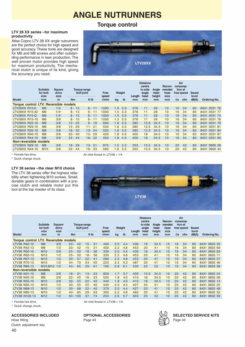
40
LTV28XX
LTV38
ANGLE NUTRUNNERSTorque control
Distance Aircentre Recom- consump-
Suitable Square Torque range to side Angle mended tion atfor bolt drive Soft joint Free Weight angle head hose free speed Sound
size size speed Length head height size levelModel mm in Nm ft lb r/min kg lb mm mm mm mm l/s cfm dB(A) Ordering No.
Torque control LTV. Reversible modelsLTV28XX R15-6 M6 1/4 8 - 15 6- 11 1000 1.5 3.3 378 11 28 10 16 34 80 8431 0531 76LTV28XX R15-42 M6 1/4a 8 - 15 6- 11 1000 1.5 3.3 378 11 28 10 16 34 80 8431 0531 77LTV28XX R15-Q M6 1/4b 8 - 15 6- 11 1000 1.5 3.3 378 11 28 10 16 34 80 8431 0531 74LTV28XX R15-10 M6 3/8 8 - 15 6- 11 1000 1.5 3.3 378 11 28 10 16 34 80 8431 0531 78LTV28XX R25-10 M8 3/8 12 - 25 9- 18 660 1.6 3.5 385 13.5 34.5 10 16 34 80 8431 0531 79LTV28XX R29-10 M8 3/8 15 - 29 11- 21 550 1.6 3.5 385 13.5 34.5 10 16 34 80 8431 0531 81LTV28XX R32-10 M8 3/8 18 - 32 13- 24 520 1.6 3.5 385 13.5 34.5 10 16 34 80 8431 0531 84LTV28XX R40-10 M8 3/8 20 - 40 15- 29 420 1.8 4.0 400 18 34.5 10 16 34 80 8431 0531 87LTV28XX R44-10 M8 3/8 25 - 44 18- 32 350 1.8 4.0 400 18 34.5 10 16 34 80 8431 0531 90Non-reversible modelsLTV28XX N29-10 M8 3/8 18 - 29 13- 21 875 1.5 3.3 353 13.5 34.5 10 20 42 80 8431 0600 29LTV28XX N44-10 M10 3/8 22 - 44 16- 33 560 1.6 3.5 353 13.5 34.5 10 20 42 80 8431 0600 44
LTV 38 series – the clear M10 choiceThe LTV 38 series offer the highest relia-bility when tightening M10 screws. Small,durable gears in combination with a pre-cise clutch and reliable motor put thistool at the top master of its class.
Air inlet thread in: LTV28 = 1/4.
LTV 28 XX series – for maximumproductivityAtlas Copco LTV 28 XX angle nutrunnersare the perfect choice for high speed andgood accuracy. These tools are designedfor M6 and M8 screws and offer outstan-ding performance in lean production. Thewell proven motor provides high speedfor maximum productivity. The mecha-nical clutch is unique of its kind, givingthe accuracy you need.
Distance Aircentre Recom- consump-
Suitable Squarec Torque range to side Angle mended tion atfor bolt drive Soft joint Free Weight angle head hose free speed Sound
size size speed Length head height size levelModel mm in Nm ft lb r/min kg lb mm mm mm mm l/s cfm dB(A) Ordering No.
Torque control LTV. Reversible modelsLTV38 R42-10 M8 3/8 20 - 42 15 - 31 400 2.0 4.4 436 18 34.5 10 16 34 80 8431 0603 55LTV38 R42-13 M8 1/2 20 - 42 15 - 31 400 2.2 4.8 453 20 41 10 16 34 80 8431 0603 69LTV38 R50-10 M10 3/8 25 - 50 18 - 36 330 2.0 4.4 436 18 34.5 10 16 34 80 8431 0603 63LTV38 R50-13 M10 1/2 25 - 50 18 - 36 330 2.2 4.8 453 20 41 10 16 34 80 8431 0603 71LTV38 R57-13 M10 1/2 30 - 57 22 - 41 280 2.2 4.8 453 20 41 10 16 34 80 8431 0603 51LTV38 R70-13 M10 1/2 34 - 70 24 - 50 225 2.4 5.3 487 20 41 10 16 34 80 8431 0603 46LTV38 R85-13 M10-M12 1/2 40 - 85 29 - 61 190 2.8 6.1 530 25 52 10 16 34 80 8431 0603 38Non-reversible modelsLTV38 N31-10 M8 3/8 18 - 31 13 - 23 800 1.7 3.7 400 13.5 34.5 10 20 42 80 8431 0602 04LTV38 N45-10 M8 3/8 22 - 45 16 - 33 520 1.8 4.0 410 18 34.5 10 20 42 80 8431 0602 06LTV38 N55-10 M10 3/8 30 - 55 22 - 40 440 1.8 4.0 410 18 34.5 10 20 42 80 8431 0602 14LTV38 N55-13 M10 1/2 30 - 55 22 - 40 440 2.0 4.4 427 20 41 10 20 42 80 8431 0602 22LTV38 N68-13 M10 1/2 30 - 68 22 - 40 370 2.0 4.4 427 20 41 10 20 42 80 8431 0602 48LTV38 N85-13 M10 1/2 40 - 85 29 - 63 300 2.2 4.8 460 20 41 10 20 42 80 8431 0602 52LTV38 N100-13 M12 1/2 50 - 100 37 - 74 250 2.6 5.7 503 25 52 10 20 42 80 8431 0602 59
SELECTED SERVICE KITSPage 43
OPTIONAL ACCESSORIESPage 43
ACCESSORIES INCLUDEDHose fitting
Clutch adjustment key
Air inlet thread in: LTV38 = 1/4.a Female hex drive.b Quick change chuck.
a Female hex drive.b Quick change chuck.
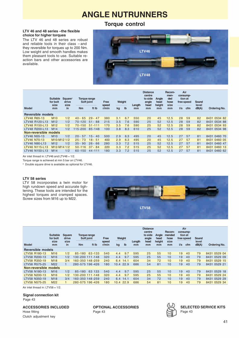
41
LTV46
LTV48
LTV58
SELECTED SERVICE KITSPage 43
OPTIONAL ACCESSORIESPage 43
ACCESSORIES INCLUDEDHose fitting
Clutch adjustment key
Distance Recom- Aircentre men- consump-
Suitable Squarea Torque range to side Angle ded tion atfor bolt drive Soft joint Free Weight angle head hose free speed Sound
size size speed Length head height size levelModel mm in Nm ft lb r/min kg lb mm mm mm mm l/s cfm dB(A) Ordering No.
Reversible modelsLTV48 R65-13 M10 1/2 40 - 65 29 - 47 380 3.1 6.7 550 20 45 12.5 28 59 82 8431 0534 82LTV48 R120-L13 M12 1/2 70 -120 51 - 88 215 3.5 7.6 590 25 52 12.5 28 59 82 8431 0534 88LTV48 R150-L13 M12 1/2 70 -150 51 -111 170 3.5 7.6 590 25 52 12.5 28 59 82 8431 0534 93LTV48 R200-L13 M14 1/2 115 -200 85 -148 100 3.8 8.3 610 25 52 12.5 28 59 82 8431 0534 98Non-reversible modelsLTV46 N55-13 M10 1/2 20 - 57 15 - 40 500 2.9 6.3 495 20 45 12.5 27 57 81 8431 0460 70LTV46 N70-13 M10-M12 1/2 25 - 73 18 - 51 400 2.9 6.3 495 20 45 12.5 27 57 81 8431 0460 05LTV46 N90-L13 M12 1/2 35 - 90 26 - 66 280 3.3 7.2 515 25 52 12.5 27 57 81 8431 0460 47LTV46 N115-L13 M12-M14 1/2 50 -116 37 - 84 220 3.3 7.2 515 25 52 12.5 27 57 81 8431 0460 13LTV46 N150-L13 M14 1/2 60 -150 44 -111 180 3.3 7.2 515 25 52 12.5 27 57 81 8431 0460 62
Signal connection kitPage 43
Distance Aircentre Recom- consump-
Suitable Square Torque range to side Angle mended tion atfor bolt drive Soft joint Free Weight angle head hose free speed Sound
size size speed Length head height size levelModel mm in Nm ft lb r/min kg lb mm mm mm mm l/s cfm dB(A) Ordering No.
Reversible modelsLTV58 R180-13 M16 1/2 85 -180 63 -133 540 4.4 9.7 595 25 55 10 19 40 79 8431 0529 04LTV58 R200-13 M16 1/2 130 -200 111 -148 320 4.4 9.7 595 25 55 10 19 40 79 8431 0529 09LTV58 R350-19 M18 3/4 160 -350 148 -259 240 6.4 14.1 604 34 72 10 19 40 79 8431 0529 15LTV58 R575-25 M22 1 280 -575 196 -426 180 10.4 22.9 686 54 81 10 19 40 79 8431 0529 21Non-reversible modelsLTV58 N180-13 M16 1/2 85 -180 63 133 540 4.4 9.7 595 25 55 10 19 40 79 8431 0529 18LTV58 N200-13 M16 1/2 130 -200 111 -148 320 4.4 9.7 595 25 55 10 19 40 79 8431 0529 24LTV58 N350-19 M18 3/4 160 -350 148 -259 240 6.4 14.1 604 34 72 10 19 40 79 8431 0529 29LTV58 N575-25 M22 1 280 -575 196 -426 180 10.4 22.9 686 54 81 10 19 40 79 8431 0529 34
Air inlet thread in: LTV46 and LTV48 = 1/2.Torque range is achieved at min 5 bar on LTV46.a Double square drive is available as optional for LTV46.
Air inlet thread in: LTV58 = 1/2.
LTV 46 and 48 series – the flexiblechoice for higher torquesThe LTV 46 and 48 series are robustand reliable tools in their class – andthey reversible for torques up to 200 Nm.Low weight and smooth handles makesthem pleasant tools to use. Suitable re-action bars and other accessories areavailable.
LTV 58 seriesLTV 58 incorporates a twin motor forhigh rundown speed and accurate tigh-tening. These tools are intended for thehighest torques and cramped spaces.Screw sizes from M16 up to M22.
ANGLE NUTRUNNERSTorque control

42
LBR
LMK
LMV
Distancecentre Air con- Recom-
Suitable Square Torque to side Angle sumption at mended Airfor bolt drive at 6 bar Free Weight angle head free speed hose inlet Sound
size size speed Length head height size thread levelModel mm in Nm ft lb r/min kg lb mm mm mm l/s cfm mm in dB(A) Ordering No.
Angle nutrunners stall type, reversible modelLMV28 R11-10 M6 3/8 11 8 1200 1.1 2.4 264 11 28 10 21 10 1/4 76 8431 0591 07LMV28 R14-10 M6 3/8 14 10 910 1.1 2.4 264 13.5 29.5 10 21 10 1/4 76 8431 0591 09
Angle nutrunners stall type, non reversible modelLMV28 N16-10 M6 3/8 16 12 1000 1.0 2.2 239 13.5 29.5 11 23 10 1/4 76 8431 0590 17
Ratchet wrenchesLBR33 S26/114-13 M8 13a 22 16 185 1.4 3.1 290 13 15 9.5 20 10 1/4 90 8431 0345 71LBR33 S26/118-16 M8-M10 16a 30 22 135 1.4 3.1 300 18 15 9.5 20 10 1/4 91 8431 0346 70LBR33 S26/118-17 M8-M10 17a 30 22 135 1.4 3.1 300 18 15 9.5 20 10 1/4 91 8431 0346 62
Worm drive nutrunnersLMK22 S004 M8 7/16a 19 14 450 1.0 2.2 240 31 30 6 13 6 1/4 90 8431 0242 26LMK22 S002 M10 7/16a 23 17 200 1.0 2.2 240 31 30 6 13 6 1/4 90 8431 0242 18LMK33 S005 M10 7/16a 29 21 480 1.7 3.7 263 41 39 9.5 20 10 1/4 90 8431 0343 24LMK33 S002 M10-M12 7/16a 32 24 235 1.9 4.2 291 41 39 9.5 20 10 1/4 90 8431 0343 16LMK33 S001 M10-M12 7/16a 55 41 130 2.2 4.9 385 41 39 9.5 20 10 1/4 90 8431 0343 08
Ordering No. Ordering No.Dimensions LBR33 S26/114 LBR33 S26/118
1/2" hex 3/8" square drive 4090 0163 00 4090 0163 001/2" hex 1/2" square drive 4090 0164 00 4090 0164 00
Dimensions Ordering No. Ordering No. Dimensions Ordering No. Ordering No.in LBR33 S26/114 LBR33 S26/118 mm LBR33 S26/114 LBR33 S26/118
1/4 4210 0360 05 – 10 4210 0414 10 –5/16 4210 0360 02 – 12 4210 0414 12 4210 0418 123/8 4210 0360 03 4210 0389 02 13 4210 0414 13 4210 0418 13
7/16 4210 0360 04 4210 0389 03 14 4210 0414 14 4210 0418 141/2 4210 0360 01 4210 0389 04 15 4210 0414 15 4210 0418 15
9/16 – 4 210 0389 06 16 – 4210 0418 165/8 – 4210 0389 01 17 – 4210 0418 173/4 – 4210 0389 05 18 – 4210 0418 18
19 – 4210 0389 05
ANGLE NUTRUNNERSAngle, stall type – Ratchet wrenches – Worm drive
Angle nutrunnersBolt capacity M6❏ Independent of joint variation – Low
inertia design gives accurate torqueindependent of joint stiffness, in otherwords low mean shift.
❏ Easy torque setting – by adjustingthe inlet air pressure.
❏ Reliable – well-proven design.❏ Good accessibility – due to small
dimensioned angle head.
Ratchet wrenchesBolt capacity M8 – M10❏ Unique accessibility – The ratchet
wrench is a superior tool, for limitedspace applications.
❏ To loosen – turn the tool upside down.
Worm-drive nutrunnersBolt capacity M8 – M12❏ Teasing throttle characteristics –Give you a significantly reduced freespeed. The worm-drive nutrunners cantherefore be used for:
ACCESSORIES INCLUDEDHose fittingSocket adaptor 3/8" square drive,LMK22 1/2" square drive, LMK33
a Female hex drive.
OPTIONAL ACCESSORIES. Socket adapters for LBR
Female hex sockets for LBR
NOTE: That 1/2" female hex sockets must be used together with socket adapters.
– Nutrunning – Light reaming– Tapping – Tube-rolling
Can also be used for incorporation in rigsas air motors for intermittent operation.
SELECTED SERVICE KITSPage 43

43
L
ACCESSORIESFor angle nutrunners
Suspension yokeProtective Reaction Signal connection
Model Exhaust hose Fixed Swivelling cover bar kit kit (-RE)
LTV08 4210 4015 00 4210 4022 90
LTV18 R07 4210 1631 81 4210 4014 00 4210 4023 90
LTV18 R15 4210 1631 81 4210 4013 00 4210 4023 90
LTV28 R07 4210 2053 00 4210 1631 82 4210 3931 80 4210 3990 00 4210 4019 90
LTV28, all models except R07 4210 2053 00 4210 1631 82 4210 3931 80 4210 3990 00 4210 4018 90
LTV28XX R15/R25/R29/R32 4210 2053 00 4210 1631 82 4210 3931 80 4210 3990 00 4210 4017 90
LTV28XX R40/44 4210 2053 00 4210 1631 82 4210 3931 80 4210 3991 00 4210 4017 90
LTV38 R42/R50/R57/N31/N45/N55/N68, 4210 2053 00 4210 1631 82 4210 3931 81 4210 3992 00 (not LTC) 4210 4017 90LTC38, LTV38 FS
LTV38 R70/N85 4210 2053 00 4210 1631 82 4210 3931 81 4210 4003 00 4210 4017 90
LTV38 R85/N100, LTV38 HAD 4210 2053 00 4210 1631 82 4210 3931 81 4210 4004 00 4210 4020 80 4210 4017 90
LTV48 R65 4210 4011 00 4210 4061 80 4210 4021 80 4210 4058 00 4210 4020 80 4210 4057 90
LTV48 R120/R150/R200, LTC48, 4210 4011 00 4210 4061 80 4210 4021 80 4210 4059 00 4210 4020 80 4210 4057 90LTV48 FS, LTV48 HAD
LTV58 R200 4210 4011 00 4210 4021 80 4210 4059 00 4210 4020 80
LTV58 R350 4210 3088 80 included
LTV46, LTC46, LTV46 FS, LTV46 HAD 4220 0312 90
SELECTED SERVICE KITSThe spare parts included inthe service kits cover a normaloverhaul of your tool. Alwayshave them available for a fastand economical repair.
Main parts included:
❏ Vane kit
❏ Motor bearings
❏ Gaskets
❏ O-rings
❏ Circlips
❏ Pins etc.
Model Service kit
LTV46 SR/LTC46 4081 0104 90LTV08 R 4081 0084 90LTV18 R 4081 0085 90LTV28 R 4081 0102 90LTV28 X 4081 0209 90LTV28 N 4081 0107 90LTV38 N 4081 0108 90LTV38 R 4081 0103 90
Including the most common wear parts. For completeinformation, see spare parts list.
Extensions for LTV
Length ofextension –"L"
Suitablefor tool mm in Ordering No.
LTV28 75 3 4210 3491 93LTV28 150 6 4210 3491 95LTV38 (not R70/R85) 75 3 4210 4301 80LTV38 (not R70/R85) 150 6 4210 4302 80LTV38R70/R85/LTV48 75 3 4210 4303 80LTV38R70/R85/LTV48 150 6 4210 4304 80
DIMENSIONS

44
LTV38 FS
Angle Distance Re- Airhead centre com- consump-
Suitable Torque range height to side mended tion at Airfor bolt Socket Soft joint Free Weight incl angle hose free speed inlet Sound
size size speed Length socket head size thread levelModel mm mm Nm ft lb r/min kg lb mm mm mm mm l/s cfm in dB(A) Ordering No.
Flush socket angle nutrunners LTV FS. Reversible modelsLTV28 R20 FS M6 13 8- 20 6- 15 500 1.4 3.1 352 34 13.5 10 10 21 1/4 76 8431 0608 02LTV28 R28 FS M8 13 14- 28 10- 21 340 1.4 3.1 350 34 – 10 10 21 1/4 76 8431 0608 00LTV38 R50 FS M10 15 25- 50 18- 37 360 2.2 4.8 454 53 20 10 18 38 1/4 80 8431 0609 85LTV38 R65 FS M12 16 34- 65 25- 48 280 2.6 5.7 515 53 20 10 18 38 1/4 80 8431 0609 87LTV48 R65 FS M10 16 30- 65 22- 48 400 3.1 6.7 550 53 20 12.5 28 59 3/8 82 8431 0610 08LTV48 R120 FS M12 19 70-120 37- 88 220 3.5 7.6 590 70 25 12.6 28 59 3/8 82 8431 0610 12LTV48 R150 FS M12 19 70-150 44-111 180 3.5 7.6 590 70 25 12.7 28 59 3/8 82 8431 0610 17LTV48 R200 FS M14 19 115-200 85-148 100 3.8 8.3 610 70 25 12.8 28 59 3/8 82 8431 0610 21
Non-reversible modelsLTV38 N55 FS M10 15 30- 55 22- 40 440 2.0 4.4 441 53 20 10 20 42 1/4 80 8431 0609 89LTV38 N85 FS M10 15 40- 85 29- 63 300 2.2 4.8 460 53 20 10 20 42 1/4 80 8431 0609 93LTV46 N55 FS M10 16 20- 57 15- 42 500 2.9 6.3 495 53 20 12.5 27 57 1/2 81 8431 0463 77LTV46 N70 FS M10-M12 16 25- 73 18- 54 400 2.9 6.3 495 53 20 12.5 27 57 1/2 81 8431 0463 69LTV46 N90 FS M12 19 35- 90 26- 66 280 3.3 7.2 515 70 25 12.5 27 57 1/2 81 8431 0463 51LTV46 N115 FS M12 19 50-116 37- 85 220 3.3 7.2 515 70 25 12.5 27 57 1/2 81 8431 0463 44LTV46 N150 FS M12-M14 19 60-150 44-111 180 3.3 7.2 515 70 25 12.5 27 57 1/2 81 8431 0463 36
ANGLE NUTRUNNERSFlush socket type
LTV FS Flush Socket toolsA good solution for access problemswhere minimum angle head size andhigh torque accuracy is required is theLTV FS. The flush socket tools have inte-grated sockets to achieve a reducedangle head height.
The LTV46 FS nutrunners are basedupon the LTV range of angle nutrunnersand offer the same tightening character-istics. They have the same motor, clutchand gear parts as the LTV range.
ACCESSORIES INCLUDEDHose fittingClutch adjustment key
Torque range is achieved at min 5 bar on LTV46/48.
NOTE: Socket mounted according to table above, other sizes available according to page 45.

45
4034
13.5
18
50
20
57.5
26
Sockets for LTV38 R65/N85 FS, LTV48 R65 FS and LTV46 N55 FS/N70 FSIntegrated sockets
Width across flats Socket extension Socket diameter Socket type Bit lockmm/in mm mm principle Ordering No.
10 3.3 27.5 HEX 4220 1621 0411 2.8 27.5 HEX Side hole 4220 0815 0112 3.3 27.5 HEX 4210 2749 0313 3.3 27.5 HEX 4210 2749 0113 22.3 27.5 HEX 4220 0815 0014 3.3 27.5 HEX 4220 2749 0415 1.3 27.5 HEX 4220 1621 0115 3.3 27.5 HEX 4210 2749 0215 8.3 27.5 HEX Special 4210 2749 1015 16.3 27.5 HEX 4220 1621 0016 0.5 27.5 HEX 4220 1251 0016 4.3 27.5 HEX 4220 2882 0117 4.3 27.5 HEX 4220 2882 0218 4.3 27.5 HEX 4220 2882 03
7/16" 3.3 27.5 HEX 4210 2749 069/16" 3.3 27.5 HEX 4210 2749 05
Socket for LTV38 R50 FS/N55 FSIntegrated sockets
Width across flats Socket extension Socket diameter Socket type Bit lockmm/in mm mm principle Ordering No.
12.7=1/2" 0.1 20.9 HEX 4220 1676 3313 0.1 20.9 HEX 4220 1676 0113 10.1 20.9 HEX 4220 1676 1313 21.1 20.9 HEX 4220 1676 2314 0.1 20.9 HEX 4220 1676 1415 0.1 20.9 HEX 4220 1676 15
7.95=5/16" 0.1 20.9 HEX special 4220 1676 048=5/16" 12.1 20.9 HEX special 4220 1676 06
ACCESSORIESFor flush socket tools
Sockets for LTV46 N90 FS/N115 FS/N150 FS and LTV48 R120 FS/R150 FS/R200 FSIntegrated sockets
Width across flats Socket extension Socket diameter Bit lockmm mm mm principle Ordering No.
Hex15 6.5 37.5 SF 4210 3534 1517 8.5 37.5 SF 4210 3534 1718 2 37.5 SF 4210 3534 6818 5.5 41.5 SF 4210 1595 0218 8.5 37.5 SF 4210 3534 1819 9.5 37.5 SF 4210 3534 1921 10.5 37.5 SF 4210 3534 2122 10.5 37.5 SF 4210 3534 2224 10.5 37.5 SF 4210 3534 2424 13.5 41.5 SF 4210 1595 0127 13.8 40.5 SF 4210 3534 27
Female TorxE-10 5.5 37.5 Female TX 4210 3534 30E-12 5.5 37.5 Female TX 4210 3534 32E-14 5.5 37.5 Female TX 4210 3534 34E-16 5.5 37.5 Female TX 4210 3534 36E-18 5.5 37.5 Female TX 4210 3534 38E-20 5.5 37.5 Female TX 4210 3534 40E-20 8.5 40.5 Female TX 4220 2044 01
Sockets for LTV28 R20 FS/R28 FSIntegrated sockets
Socketextension
Socket diameter
Socketextension
Socket diameter
Socketextension
Socket diameter
Socketexten-sion Socket diameter
Width across flats Socket extension Socket diameter Socket type Bit lockmm/in mm mm principle Ordering No.
10 0 17.9 HEX 4220 1589 1010 15 17.9 HEX 4220 1589 2013 0 17.9 HEX 4220 1589 1313 2 17.9 HEX 4220 1589 3313 5 17.9 HEX 4220 1589 2313 15 17.9 HEX 4220 1589 34
6.35=1/4" 0 17.9 HEX, bit holder magnet 4220 1589 148=5/16" 0 17.9 HEX, bit holder magnet 4220 1589 08
Other dimensions on request.
Other dimensions on request.

46
H
C
B
LTC38
ANGLE NUTRUNNERSCrowfoot type
LTC Crowfoot toolsBolt capacity M8 – M14A good solution in many cases of inac-cessibility is the crowfoot, which has thesmallest height and side to centre di-mensions.
The LTC range of nutrunners are basedon the LTV range of angle nutrunnersand offers the same tightening charac-teristics. They have the same motor,clutch and gear parts as the LTV range.
The crowfoot is attached to a standardangle nutrunner LTV and can easily beadjusted ± 90o of centre line.
DIMENSIONS
Air inlet thread inch: LTC38 = 1/4", LTC46 = 1/2", LTC48 = 3/8".
NOTE: Sockets mounted according to table above, optional sizes see page 47.
AirCrowfoot Recom- consump-
Suitable Torque range dimensions mended tion atfor bolt Socket Soft joint Free Weight hose free speed Sound
size size speed Length H B C size levelModel mm mm Nm ft lb r/min kg lb mm mm mm mm mm l/s cfm dB(A) Ordering No.
ReversibleLTC38 R33-13-A-O-3 M8 13 16- 33 12-24 430 2.6 5.7 508 19 32 16 10 18 38 80 8431 0611 01LTC38 R40-17-A-O-3 M10 13 23- 40 17-29 360 3.0 6.6 540 19 39 20 10 18 38 80 8431 0611 08LTC48 R56-17-A-O-3 M10-M12 17 24- 56 18-41 400 3.9 8.6 600 19 39 20 12.5 28 59 82 8431 0611 06LTC48 R96-19-A-O-3 M12 19 40- 96 30-71 220 4.3 9.5 640 25 39 20 12.5 28 59 82 8431 0611 11LTC48 R120-19-A-O-3 M12-M14 19 48-120 36-89 180 4.3 9.5 640 25 39 20 12.5 28 59 82 8431 0611 15
Non-reversibleLTC38 N41-13-A-O-3 M8 13 18- 41 13-30 520 2.4 5.3 479 19 32 16 10 20 42 80 8431 0611 10LTC38 N48-17-A-O-3 M10 17 24- 48 17-35 440 2.8 6.1 511 19 39 20 10 20 42 80 8431 0611 09LTC46 N46-17-A-O-3 M10 17 16- 46 12-34 500 3.5 7.7 561 19 39 20 12.5 27 57 81 8431 0468 07LTC46 N55-17-A-O-3 M10 17 20- 55 15-40 400 3.5 7.7 561 19 39 20 12.5 27 57 81 8431 0469 06LTC46 N78-19-A-O-3 M12 19 28- 78 21-57 280 4.1 9.0 577 25 39 20 12.5 27 57 81 8431 0470 03LTC46 N93-19-A-O-3 M12 19 40- 93 29-69 220 4.1 9.0 577 25 39 20 12.5 27 57 81 8431 0471 02LTC46 N120-19-A-O-3 M12 19 48-120 35-88 180 4.1 9.0 577 25 39 20 12.5 27 57 81 8431 0472 01
Extensive range of crowfoot and open end tools, seespecial leaflet, "Atlas Copco tool attachments" Order-ing No. 9833 1361 01 and CD "Ordering information"Ordering No. 9833 1381 01.
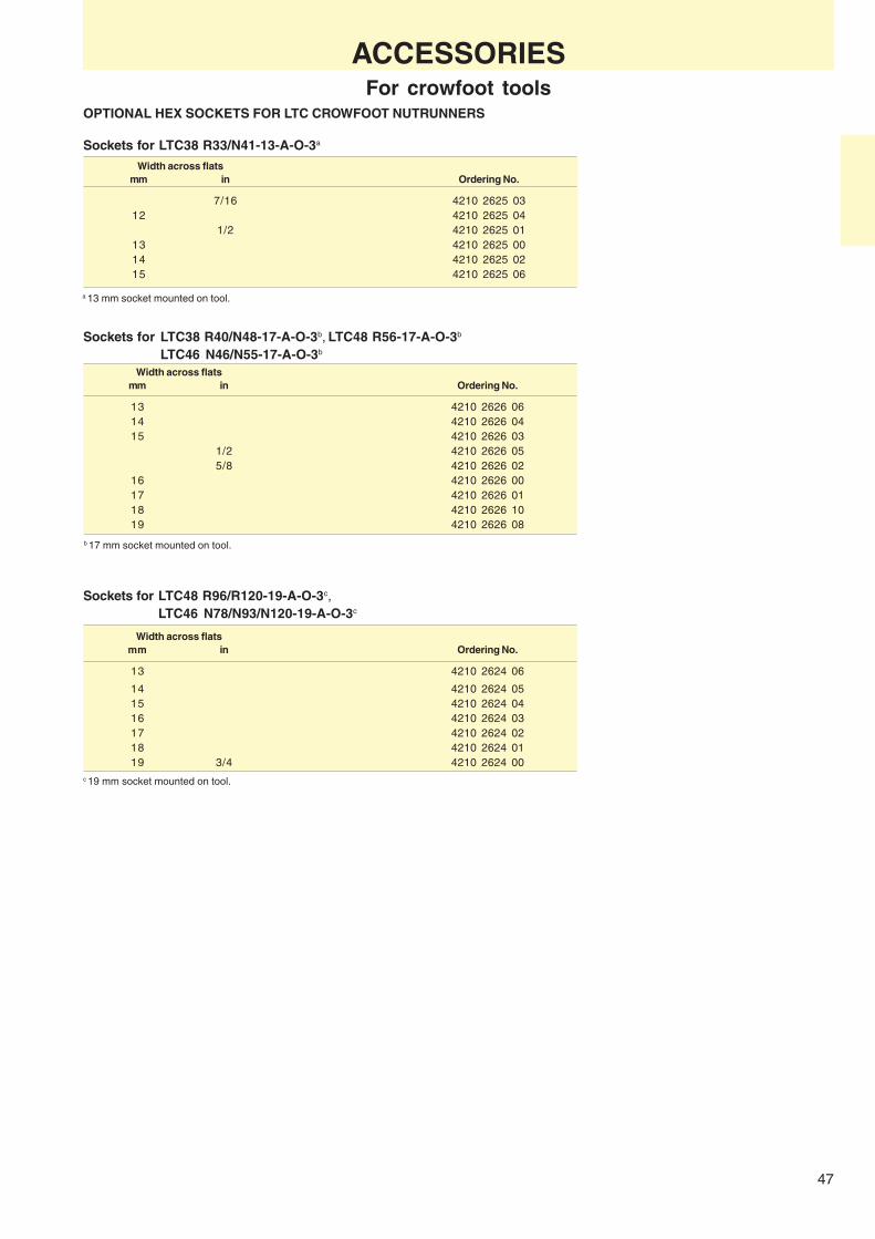
47
OPTIONAL HEX SOCKETS FOR LTC CROWFOOT NUTRUNNERS
Sockets for LTC38 R33/N41-13-A-O-3a
Width across flatsmm in Ordering No.
7/16 4210 2625 0312 4210 2625 04
1/2 4210 2625 0113 4210 2625 0014 4210 2625 0215 4210 2625 06
Width across flatsmm in Ordering No.
13 4210 2626 0614 4210 2626 0415 4210 2626 03
1/2 4210 2626 055/8 4210 2626 02
16 4210 2626 0017 4210 2626 0118 4210 2626 1019 4210 2626 08
ACCESSORIESFor crowfoot tools
Sockets for LTC38 R40/N48-17-A-O-3b, LTC48 R56-17-A-O-3b
LTC46 N46/N55-17-A-O-3b
Sockets for LTC48 R96/R120-19-A-O-3c,LTC46 N78/N93/N120-19-A-O-3c
Width across flatsmm in Ordering No.
13 4210 2624 06
14 4210 2624 0515 4210 2624 0416 4210 2624 0317 4210 2624 0218 4210 2624 0119 3/4 4210 2624 00
b 17 mm socket mounted on tool.
a 13 mm socket mounted on tool.
c 19 mm socket mounted on tool.

48
LTO28 R
Tool dimensions
Torque range Max Tube nut headSoft joint Socket socket Free Weight Total
size size speed length width heightModel Nm ft lb mm mm r/min kg lb mm mm mm Ordering No.
LTO28 R12-10-K-I-3 8-12 7- 9 10 14 380 1.9 4.2 400 40 14/39 8431 0536 17LTO28 R17-13-K-I-3 12-17 4-12 13 23 285 2.1 4.6 410 52 14.4/39 8431 0536 11LTO28 R24-10-K-I-3 15-24 6-18 10 14 160 1.9 4.2 420 40 14/39 8431 0536 12LTO28 R31-17-K-I-3 18-31 7-23 17 23 140 2.1 4.6 430 52 14.4/39 8431 0536 14
ANGLE NUTRUNNERSOpen end type – Torque control
10-23 mm hexagon nut capacityBased on the well-known LTV 8 series ofangle nutrunners the LTO torque controlopen end nutrunners offer tightening oftube nuts in high-pace line production.
Applications are mainly in the assemblyof hydraulic and pneumatic brake pipesand other hose and cable connections inthe automotive and aircraft industries.
The power from the air motor is trans-ferred to the nut through a gear drivemechanism without impacting or ratch-eting.
The one-hand operated two step me-chanism simplifies the socket releaseback to open position.
Recomended hose size 10 mm.Air inlet thread: 1/4 in.NOTE: The tools are supplied with a socket gear
according to table above. Optional socketsaccording to page 49.
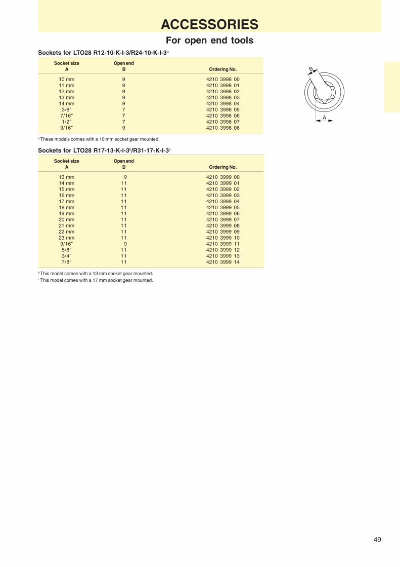
49
A
B
Sockets for LTO28 R17-13-K-I-3b/R31-17-K-I-3c
Socket size Open endA B Ordering No.
13 mm 9 4210 3999 0014 mm 11 4210 3999 0115 mm 11 4210 3999 0216 mm 11 4210 3999 0317 mm 11 4210 3999 0418 mm 11 4210 3999 0519 mm 11 4210 3999 0620 mm 11 4210 3999 0721 mm 11 4210 3999 0822 mm 11 4210 3999 0923 mm 11 4210 3999 109/16" 9 4210 3999 115/8" 11 4210 3999 123/4" 11 4210 3999 137/8" 11 4210 3999 14
Sockets for LTO28 R12-10-K-I-3/R24-10-K-I-3a
Socket size Open endA B Ordering No.
10 mm 9 4210 3998 0011 mm 9 4210 3998 0112 mm 9 4210 3998 0213 mm 9 4210 3998 0314 mm 9 4210 3998 04
3/8" 7 4210 3998 057/16" 7 4210 3998 061/2" 7 4210 3998 07
9/16" 9 4210 3998 08
ACCESSORIESFor open end tools
a These models comes with a 10 mm socket gear mounted.
b This model comes with a 13 mm socket gear mounted.c This model comes with a 17 mm socket gear mounted.

50
LTV38 HAD
ANGLE NUTRUNNERSHold and drive type
Tools for hold and drive boltsBolt capacity M10 – M14What used to be a two-man operationhas now become a one-man task. Noreaction arms.
The distinguishing feature of a holdand drive bolt is that one part is held andthe other is tightened from the sameside.
Hold and drive bolts are being usedincreasingly by, for example, truckmanufacturers on the frame assemblyline. The LTV HAD is especially suitablefor shock absorber assembly.
Atlas Copco has developed specialtools for use on hold and drive boltsbased on the standard LTV series. Thereaction torque is absorbed while thebolt is gripped during assembly.
The HAD sockets are available inthree different lengths, special socketsare available upon request.
Also suitable for break away bolts, HiLok/Hi Shear.
NOTE: The screw must be strong enough to carrythe final torque.
SELECTED SERVICE KITSPage 43
Torque rangea Weight FreeBolt speed
Model size Nm ft lb kg lb r/min Ordering No.
LTV38 R42 HAD M8 20- 42 15- 31 2.2 4.8 430 8431 0603 75LTV38 R50 HAD M10 25- 50 18- 36 2.2 4.8 360 8431 0603 82LTV46 N90 HAD M10-12 35- 90 26- 52 3.3 7.3 280 8431 0463 28LTV46 N115 HAD M12-14 50- 115 37- 85 3.3 7.3 220 8431 0463 10LTV46 N150 HAD M14 60- 150 44- 111 3.3 7.3 180 8431 0463 02LTV38 R85 HAD M10-12 40- 85 30- 67 3.0 6.5 210 8431 0609 58LTV38 R40 LT HADb M8-10 15- 40 11- 30 3.0 6.5 210 8431 0609 52LTV48 R120 HAD M12-14 70- 120 52- 89 3.3 7.3 220 8431 0610 26LTV48 R150 HAD M14 70- 150 52- 111 3.3 7.3 180 8431 0610 30LTV48 R200 HAD M14 115- 200 85- 150 3.3 7.3 100 8431 0610 32LTV58 R350 HAD M18 160- 350 150- 260 6.4 14.1 240 8431 0529 65
a At min 5 bar.b For low torque applications.
NOTE: Sockets and holders have to be ordered separately see page 51.Other types of Hold and Drive equipped tools are available on special request.
ACCESSORIES INCLUDEDHose fittingClutch adjustment key
OPTIONAL ACCESSORIESPage 43

51
A B C
Ø D
A B C
A
CB
A
CB
A
CB
A B C 18.5
61
Ø D 1.5
26
76
5 Ø D
= 33
= 53
= 73
34.5
102
.5
= 33
= 53
= 73
= 34
= 54
= 74
ACCESSORIESFor hold and drive tools
Measurements in mm
Nut socket For LTV38 R40 LT/R 85 HAD, LTV48 HAD and LTV46 HAD (Fig. 2)Width across Ordering No.
flats SocketW mm Ø D mm
13 30 4210 3513 13 4210 3513 33 4210 3513 5314 30 4210 3513 14 4210 3513 34 4210 3513 5415 30 4210 3513 15 4210 3513 35 4210 3513 5516 30 4210 3513 16 4210 3513 36 4210 3513 5617 30 4210 3513 17 4210 3513 37 4210 3513 5718 31 4210 3513 18 4210 3513 38 4210 3513 5819 32 4210 3513 19 4210 3513 39 4210 3513 5921 35 4210 3513 21 4210 3513 41 4210 3513 6122 35 4210 3513 22 4210 3513 42 4210 3513 6224 35 4210 3513 24 4210 3513 44 4210 3513 64
Figure 2
Nut socket For LTV58 R350-HAD (Fig. 3)
Width across Ordering No.flats Socket
W mm Ø D mm
18 41 4220 1778 04 4220 1778 14 4220 1778 2419 41 4220 1778 05 4220 1778 15 4220 1778 2520 41 4220 1778 06 4220 1778 16 4220 1778 2621 41 4220 1778 07 4220 1778 17 4220 1778 2722 41 4220 1778 08 4220 1778 18 4220 1778 2823 41 4220 1778 09 4220 1778 19 4220 1778 2924 41 4220 1778 01 4220 1778 11 4220 1778 2125 41 4220 1778 02 4220 1778 12 4220 1778 22
25.4=1" 41 4220 1778 10 4220 1778 20 4220 1778 3026 41 4220 1778 03 4220 1778 13 4220 1778 2327 46 – 4220 2139 84 4220 2139 9428 46 – 4220 2139 83 4220 2139 9329 46 – 4220 2139 82 4220 2139 9230 46 – 4220 2139 81 4220 2139 9131 54 – 4220 2297 81 4220 2297 9132 54 – 4220 2297 82 4220 2297 9233 54 – 4220 2297 83 4220 2297 9334 54 – 4220 2297 84 4220 2297 9435 54 – 4220 2297 85 4220 2297 9536 54 – 4220 2297 86 4220 2297 96
Figure 3
Figure 1
Nut socket For LTV38 R42-HAD/LTV38 R50-HAD (Fig. 1)Width across Ordering No.
flats SocketW mm Ø D mm
10 22 4220 1769 16 4220 1769 31 4220 1769 5111 22 4220 1769 15 4220 1769 32 4220 1769 5212 22 4220 1769 13 4220 1769 33 4220 1769 5313 22 4220 1769 09 4220 1769 12 4220 1769 5414 22 4220 1769 05 4220 1769 35 4220 1769 0815 22 4220 1769 14 4220 1769 36 4220 1769 5616 25 4220 1888 71 4220 1888 81 4220 1888 9117 25 4220 1888 72 4220 1888 82 4220 1888 9218 26 4220 1888 73 4220 1888 83 4220 1888 9319 27 4220 1888 74 4220 1888 84 4220 1888 9420 31 4220 1888 75 4220 1888 85 4220 1888 9521 31 4220 1888 76 4220 1888 86 4220 1888 96
30 travel
40 travel
30 travel

52
Y
X
W
N
W
N
W
A B C
A B C
A B C
A B C
A B C
A B C
Screw holder – Male hexagon for LTV38 R40 LT/R85 HAD, LTV48 HAD and LTV46 HADSuitable Ordering No.
Dimension socket sizeN mm mm
7 14-24 4210 2825 41 4210 2825 42 4210 2825 43 8 14-24 4210 2825 01 4210 2825 05 4210 2825 09 9 15-24 4210 2825 02 4210 2825 06 4210 2825 1010 18-24 4210 2825 03 4210 2825 07 4210 2825 1111 19-24 4210 2825 04 4210 2825 08 4210 2825 1212 19-24 4210 2825 13 4210 2825 14 4210 2825 15
Two flats
Male hexagon
Female hexagon
Bit holder
Bit13
Screw holder – Two flats for LTV38 R40 LT/R85 HAD, LTV48 HAD and LTV46 HAD
Bit holder 5/16" 5/16" Bits
Width N, mm Ordering No.
Screw holder – Female hexagon for LTV38 R40 LT/R85 HAD, LTV48 HAD and LTV46 HAD
4210 2991 91 4210 2991 92 4210 2991 93 5 4023 1215 00 6 4023 1216 00 7 4023 1219 00 8 4023 1217 0010 4023 1218 00
Screw holder – Female hexagon for LTV38 R42-HAD/LTV38 R50-HAD
Bit holder 1/4"
Width N, mm Bits
4220 1959 01 4220 1959 04 4220 1959 03 10-21 1/4"
Screw holder – Two flats for LTV38 R42-HAD/LTV38 R50-HAD
ACCESSORIESFor hold and drive tools
Dimension Suitable Ordering No.X x Y socket sizemm mm
6.6 x 5 10-21 4220 1770 19 – –7 x 5 10-21 – 4220 1770 17 –
5.1 x 8.2 10-21 4220 1770 01 – 4220 1770 16 8 x 6 10-21 4220 1770 02 – –
Dimension Suitable Ordering No.X x Y socket sizemm mm
8 x 6.3 15-24 4210 2694 17 4210 2694 18 4210 2694 198 x 6 15-24 4210 2694 05 4210 2694 10 4210 2694 15
9.55 x 7.6 18-24 4210 2694 01 4210 2694 06 4210 2694 1111.20 x 8.9 19-24 4210 2694 02 4210 2694 07 4210 2694 12
13 x 9.8 19-24 4210 2694 03 4210 2694 08 4210 2694 1313.20 x 10.5 19-24 4210 2694 04 4210 2694 09 4210 2694 14
Screw holder – Female hexagon for L TV58 R350-HAD
NOTE: 8 mm bit is included in the bit holders.
Ordering No.Socket size
Bit holder mm
7 14-24 4210 2825 41 4210 2825 42 4210 2825 435/16" 18-20 4220 1777 88 4220 1777 89 4220 1777 905/16" 21-36 4220 1777 82 4220 1777 85 4220 1777 87

53
LTD
STRAIGHT NUTRUNNERSHand-held and fixture mounted
The Atlas Copco LTD straight nutrunnersare used in hand-held applications andas components in systems for assemblystations, e.g. for:❏ Articulating arms – Where a fixed
support on the work piece for a reac-tion bar is not available a telescopicor articulated arm mounted LTD nut-runner might be the ideal solution.
❏ Second fastener – By combining twoLTD straight nutrunners in a twinspindle unit the screws can be tight-ened simultaneously.
❏ Sequence tightening – The LTDsystem offers a flexible, low-cost solu-tion to many advanced tighteningrequirements.
❏ Automatic systems – The LTDstraight nutrunner is the ideal basictightening unit in automatic and re-motely controlled assembly systems.
❏ Torque accuracy – Fixtured toolsmeans that operator influence is mini-mized.
❏ Reaction bar blanks – For singlespindle hand-held applications.
❏ Mounting plates – The LTD/LMDstraight nutrunners have a splinedreaction bar connection which canalso be used for fixed assembly ofthe nutrunner. A number of standardmounting plates are available toorder.
❏ Floating square drive – For two ormore spindles the units must usuallyhave floating spindles to compensatefor run-down variations. Models withfloating square drive or telescopicfront parts are available.
❏ Fixture punches – For mounting ofthe nutrunner to locally made baseplates a punch for the splinesconnection is available as optionalequipment.
❏ TwinSpin Kit – A kit for building yourown twin spindle assembly unit isavailable as extra equipment.
❏ Remote control – Remote controlvalves are available as optionalequipment.
❏ Air signal outlets – All LTD modelsare equipped with air signal outletsfor completed operation.
The LTD system
❏ Electronic control – Integrated torqueand angle transducers and electronicinstruments offer a wide selection ofoptions for advanced tightening mo-nitoring and control. Tools with angleencoders and torque transducers onrequest.
Mounts Spindles Nutrunner motors Remote control
Reaction bar
Mounting plate
Fixture punch
Kits
Fixed square drive
Floating square drive
Non reversible
Manual or remote control
Reversible
Manual control
Reversible
Remote control
(3-port valve)
(5-port valve)

54
LTD28
LTD51
Weight Distance Airwithout centre Recom- consump-
Suitable Square Torque range reaction to side mended Air tion atfor bolt drive Soft joint Free bar/bracket max hose inlet Sound free speed
size size speed Length width size thread levelModel mm in Nm ft lb r/min kg lb mm mm mm in dB(A) l/s cfm Ordering No.
Models with fixed square driveNon reversible, lever startLTD28 N9-RE M5-M6 3/8 5 - 9 4 - 6 1400 1.1 2.4 339 20 10 1/4 76 9 19 8431 0534 05LTD28 N18-RE M6 3/8 8 - 18 6 -13 780 1.2 2.6 358 20 10 1/4 76 9 19 8431 0534 08LTD28 N21-RE M6 3/8 10 - 21 7 -15 570 1.2 2.6 358 20 10 1/4 76 9 19 8431 0534 13LTD28 N22-RE M6 3/8 10 - 22 7 -16 140 1.2 2.6 358 20 10 1/4 76 9 19 8431 0534 18Reversible, lever startLTD28 R8-RE M5-M6 3/8 3 - 8 2 - 6 1100 1.2 2.6 363 20 10 1/4 76 8 17 8431 0534 61LTD28 R16-RE M6 3/8 7 - 16 6 -12 610 1.3 2.9 383 20 10 1/4 76 8 17 8431 0534 65LTD28 R20-RE M6-M8 3/8 10 - 20 7 - 15 520 1.3 2.9 383 20 10 1/4 76 8 17 8431 0534 51LTD28 R22-RE M6-M8 3/8 10 - 22 7 - 16 125 1.3 2.9 383 20 10 1/4 76 8 17 8431 0534 54Reversible, remote control back headLTD28 R8-RR M5-M6 3/8 3 - 8 2 - 6 1100 1.2 2.6 294 20 10/13 a 76b 8 17 8431 0703 80LTD28 R16-RR M6 3/8 7 - 16 6 -12 610 1.3 2.9 313 20 10/13 a 76b 8 17 8431 0703 82LTD28 R20-RR M6-M8 3/8 10 - 20 7 - 15 520 1.3 2.9 313 20 10/13 a 76b 8 17 8431 0703 83Models with 25 mm (1") floating square driveNon reversible, lever startLTD28 N9F-RE M5-M6 3/8 5 - 9 4 - 6 1400 1.5 3.3 447 20 10 1/4 76 9 19 8431 0534 21LTD28 N18F-RE M6 3/8 8 - 18 6 - 13 780 1.6 3.5 466 20 10 1/4 76 9 19 8431 0534 27LTD28 N21F-RE M6 3/8 10 - 21 7 - 15 570 1.6 3.5 466 20 10 1/4 76 9 19 8431 0534 39LTD28 N22F-RE M6 3/8 10 - 22 7 - 16 140 1.6 3.5 466 20 10 1/4 76 9 19 8431 0534 43Reversible, lever startLTD28 R8F-RE M5-M6 3/8 3 - 8 2 - 6 1100 1.6 3.5 471 20 10 1/4 76 8 17 8431 0534 78LTD28 R16F-RE M6 3/8 7 - 16 6 - 12 620 1.7 3.7 491 20 10 1/4 76 8 17 8431 0534 85LTD28 R20F-RE M6-M8 3/8 10 - 20 7 - 15 570 1.7 3.7 491 20 10 1/4 76 8 17 8431 0534 37LTD28 R22F-RE M6-M8 3/8 10 - 22 7 - 16 125 1.7 3.7 491 20 10 1/4 76 8 17 8431 0534 89Reversible, remote control back headLTD28 R8F-RR M5-M6 3/8 3 - 8 2 - 6 1100 1.6 3.5 401 20 10/13 a 76b 8 17 8431 0703 84LTD28 R16F-RR M6 3/8 7 - 16 6 - 12 620 1.7 3.7 421 20 10/13 a 76b 8 17 8431 0703 86LTD28 R20F-RR M6-M8 3/8 10 - 20 7 - 15 570 1.7 3.7 421 20 10/13 a 76b 8 17 8431 0703 88
STRAIGHT NUTRUNNERSShut-off type
Bolt capacity M5 – M24The LTD28, 38 and 48 straight nutrunnersare based on the power package andclutch from the LTV angle nutrunners.
The LTD/LMD51 nutrunners are basedon the unique LTP/LMP51range of twinmotor pistol grip nutrunners with fastrun-down and automatic torque-up atlow speed offering high productivity andunmatched torque accuracy and jointindependence.❏ Remote control back head – A re-
mote valve is connected to the backhead of the LTD –RR tools allowingfor a better multiple.
❏ Accessibility – Slim design allowsthe building of smooth, simple multi-ples or pare splndle designs. The lackof the clutch makes these tools shorter.
❏ Flexibility – The range of LTD toolsprovides you with the options for yourrequirements.
❏ Reversibility – Reversible LTD toolsare available.
ACCESSORIES INCLUDEDHose fitting
Clutch adjustment key
a Air inlet thread = 2 x 1/4" + 1 x 3/8".b With exhaust manifold.

55
Ø D
Ø N
M
LF t
Weight Distance Airwithout centre Recom- consump-
Suitable Square Torque range reaction to side mended Air tion atfor bolt drive Soft joint Free bar/bracket max hose inlet Sound free speed
size size speed Length width size thread levelModel mm in Nm ft lb r/min kg lb mm mm mm in dB(A) l/s cfm Ordering No.
Models with fixed square driveNon-reversible, lever startLTD38 N30-RE M8 1/2 14 - 30 10 - 21 820 2.2 4.8 414 20 10 1/4 80 16 34 8431 0535 04LTD38 N38-RE M8 1/2 20 - 38 15 - 27 680 2.2 4.8 414 20 10 1/4 80 16 34 8431 0535 12LTD38 N44-RE M8-M10 1/2 18 - 44 13 - 32 580 2.2 4.8 414 20 10 1/4 80 20 42 8431 0535 17LTD38 N55-RE M10 1/2 27 - 55 20 - 40 470 2.2 4.8 487 20 10 1/4 80 20 42 8431 0535 20Reversible, lever startLTD38 R27-RE M8 1/2 13 - 27 10 - 20 670 2.1 4.6 441 20 10 1/4 80 16 34 8431 0534 53LTD38 R32-RE M8 1/2 18 - 32 13 - 24 560 2.1 4.6 441 20 10 1/4 80 16 34 8431 0534 52LTD38 R38-RE M8-M10 1/2 19 - 38 14 - 28 480 2.1 4.6 441 20 10 1/4 80 16 34 8431 0535 78LTD38 R47-RE M8-M10 1/2 22 - 47 16 - 35 380 2.3 5.1 513 20 10 1/4 80 20 42 8431 0535 83Reversible, remote control back headLTD38 R27-RR M8 1/2 13 - 27 10 - 20 670 2.1 4.6 377 21 10/16 a 80b 16 34 8431 0704 22LTD38 R32-RR M8 1/2 18 - 32 13 - 24 560 2.1 4.6 377 21 10/16 a 80b 16 34 8431 0704 24LTD38 R38-RR M8-M10 1/2 19 - 38 14 - 28 480 2.1 4.6 377 21 10/16 a 80b 16 34 8431 0704 26LTD38 R47-RR M8-M10 1/2 22 - 47 16 - 35 380 2.3 5.1 448 21 10/16 a 80b 16 34 8431 0704 28Models with 25 mm, (1") floating square driveNon-reversible, lever startLTD38 N30F-RE M8 1/2 14 - 30 10 - 21 820 2.3 5.0 521 20 10 1/4 80 20 42 8431 0535 38LTD38 N38F-RE M8 1/2 20 - 38 15 - 27 680 2.3 5.0 521 20 10 1/4 80 20 42 8431 0535 46LTD38 N44F-RE M8-M10 1/2 18 - 44 13 - 32 580 2.3 5.0 521 20 10 1/4 80 20 42 8431 0535 31LTD38 N55F-RE M10 1/2 27 - 55 20 - 40 470 2.5 5.5 599 23 10 1/4 80 20 42 8431 0535 53Reversible, lever startLTD38 R27F-RE M8 1/2 13 - 27 10 - 20 670 2.5 5.5 546 20 10 1/4 80 16 34 8431 0535 65LTD38 R32F-RE M8 1/2 18 - 32 13 - 24 560 2.5 5.5 546 20 10 1/4 80 16 34 8431 0535 91LTD38 R38F-RE M8-M10 1/2 19 - 38 14 - 28 480 2.5 5.5 546 20 10 1/4 80 16 34 8431 0535 95LTD38 R47F-RE M8-M10 1/2 22 - 47 16 - 35 380 2.7 5.9 625 23 10 1/4 80 16 34 8431 0535 99Reversible, remote control back headLTD38 R27F-RR M8 1/2 13 - 27 10 - 20 670 2.5 5.5 482 21 10/16 a 80b 16 34 8431 0704 30LTD38 R32F-RR M8 1/2 18 - 32 13 - 24 560 2.5 5.5 482 21 10/16 a 80b 16 34 8431 0704 32LTD38 R38F-RR M8-M10 1/2 19 - 38 14 - 28 480 2.5 5.5 482 21 10/16 a 80b 16 34 8431 0704 34LTD38 R47F-RR M8-M10 1/2 22 - 47 16 - 35 380 2.7 5.9 566 23 10/16 a 80b 16 34 8431 0704 36Reversible, lever startLTD48 R65-REd M10 1/2 27 - 65 20 - 48 400 3.1 6.8 582 30 12.5 1/2 82 28 59 8431 0637 07LTD48 R81-REd M12 1/2 32 - 81 24 - 60 330 3.1 6.8 582 30 12.5 1/2 82 28 59 8431 0637 12Reversible, remote control back headLTD48 R65-RR M10 1/2 27 - 65 20 - 48 400 3.5 7.7 410 28 12.5/16 c - 30 63 8431 0704 46LTD48 R81-RR M12 1/2 32 - 81 24 - 60 330 3.5 7.7 410 28 12.5/16 c - 30 63 8431 0704 48Models with 25 mm, (1") floating square driveReversible, lever startLTD48 R65F-REd M10 1/2 27 - 65 20 - 48 400 3.5 7.7 700 30 12.5 1/2 82 28 59 8431 0637 17LTD48 R81F-REd M12 1/2 32 - 81 24 - 60 330 3.5 7.7 700 30 12.5 1/2 82 28 59 8431 0637 23Reversible, remote control back headLTD48 R65F-RR M10 1/2 27 - 65 20 - 48 400 3.7 8.2 522 28 12.5/16 c - 30 63 8431 0704 50LTD48 R81F-RR M12 1/2 27 - 65 20 - 48 330 3.7 8.2 522 28 12.5/16 c - 30 63 8431 0704 52Torque control models with fixed square driveLTD51 012-13-RE M12 1/2 45 - 100 35 - 75 1000 2.6 5.7 223 29 10 3/8 79b 19 40 8431 0525 07LTD51 008-13-RE M14 1/2 70 - 175 50 - 130 600 2.6 5.7 223 29 10 3/8 79b 19 40 8431 0525 15LTD51 006-19-RE M16 3/4 85 - 225 60 - 165 450 2.6 5.7 223 29 10 3/8 79b 19 40 8431 0525 23LTD51 006-16-RE M16 5/8 85 - 225 60 - 165 450 2.6 5.7 223 29 10 3/8 79b 19 40 8431 0525 22LTD51 004-20-RE M18 3/4 145 - 320 105 - 235 300 3.3 7.3 260 31 10 3/8 79b 19 40 8431 0525 31LTD51 002-20-RE M20 3/4 220 - 460 165 - 335 200 3.3 7.3 260 31 10 3/8 79b 19 40 8431 0525 49LTD51 001-25-RE M24 1 800 - 900 220 - 660 52 3.6 7.9 282 32 10 3/8 79b 19 40 8431 0525 21Stall type models with fixed square driveLMD51 012-13-RE M12 1/2 60 - 110 45 - 80 1100 2.6 5.7 223 29 10 3/8 79b 19 40 8431 0526 05LMD51 008-13-RE M14 1/2 95 - 190 70 - 140 680 2.6 5.7 223 29 10 3/8 79b 19 40 8431 0526 13LMD51 006-19-RE M16 3/4 182 - 250 95 - 185 520 2.6 5.7 223 29 10 3/8 79b 19 40 8431 0526 69LMD51 006-16-RE M16 5/8 182 - 250 95 - 185 520 2.6 5.7 223 29 10 3/8 79b 19 40 8431 0526 22LMD51 004-20-RE M18 3/4 195 - 380 140 - 275 305 3.3 7.3 260 31 10 3/8 79b 19 40 8431 0526 39LMD51 002-20-RE M20 3/4 260 - 550 190 - 400 210 3.3 7.3 260 31 10 3/8 79b 19 40 8431 0526 47LMD51 001-25-RE M24 1 470 - 950 345 - 695 125 3.7 8.2 282 32 10 3/8 79b 19 40 8431 0526 37
STRAIGHT NUTRUNNERSNon shut-off and shut-off types
a Air inlet thread = 2 x 1/4" + 1 x 3/8".b With exhaust manifold.
c Air inlet thread = 2 x 1/2" + 1 x 3/4".d Optional RE kit LTD48 RE Ord No. 4210 4057 90.
DIMENSIONSDimensions
N D F L M tin mm mm mm mm mm Ordering No.
LMD/LTD51 008/012 1/2 34 25 101 127 12 4210 3864 80LMD/LTD51 006-16-RE3/4 41 25 117 148 12 4210 3789 80LMD/LTD51 002/004 3/4 50 40 160 201 15 4210 3781 81LMD/LTD51 001 1 67 50 226 278 15 4210 3788 80
LTD51/LMD51: Change over torque is around 7% ofmaximum torque on a given air pressure.

56
LTD
Twin spindle fixturesAtlas Copco Tools offers three sizes oftwin spindle multiples, intended for 28,38 and 48/51 sizes. The CC-distance inthe Twinspin is changeable and thelargest size has a max CC-distance of364 mm. The smallest size has a mini-mum CC-distance of 53 mm. The com-plete set has two throttle handles, onefor forward and one for reverse, (if thesystem is non reversible there is onlyone throttle handle).
The following kits are available;❏ TwinSpin air LTD28❏ TwinSpin air LTD38❏ TwinSpin air LTD48/51
The TwinSpin kit includes;❏ 2 x support handle❏ 2 x mounting plate,
(with corresponding splines)❏ 2 x handle attachment❏ 1 x suspension wire❏ 1 x reaction arm❏ 2 x beam❏ 1 x assembly tool❏ 1 x mounting plate for reaction bar❏ 2 x post❏ 2 x bracket
Valves kitsValves have to be ordered separately. 3-gate valves are available for non re-versible applications and 5-gate valvesfor reversible. Mounting brackets for thevalve kits have to be ordered sepa-rately. For stated noise levels on RR-versions, exhaust manifolds have to beused. Exhaust manifolds have to be or-dered separately.
Valve kits include❏ Main valve❏ Throttle handle valve/valves❏ Bracket❏ Hose nipples and hose clamps
Exhaust manifolds include❏ Block❏ Silencer with gasket❏ Nipples
STRAIGHT AND SPECIAL NUTRUNNERS
TwinSpin kit Max CC-distancea Min CC-distancea Ordering No.
LTD28 RE/RR 383 53 4210 4159 80LTD38 N30/N38/N44/R27/R32/R38-RE/RR 376 60 4210 4160 80LTD38 N55/R47-RE/RR 364 72 4210 4161 80LTD48 RE/RR 364 72 4210 4161 80LMD/LTD51 006, 008, 012 364 72 4210 4161 82LMD/LTD51 002/004 362 87 4210 4161 81
Intended for tool type Valve type Ordering No.
LTD28/38 RE 3-gate for non reversible 4210 4162 80LTD28 RR 5-gate for reversible 4210 4163 80LTD48 RE 3-gate for non reversible 4210 4166 80LTD38/48 RR 5-gate for reversible 4210 4167 80LMD/LTD51 006, 008, 012 3-gate for non reversible 4210 4166 80
Intended for tool type Ordering No.
LTD28 RR 4210 4168 80LTD38 RR 4210 4168 81LTD48 RR 4210 4168 81
a CC-distance = distance between center of spindles.

57
D
L
L
W
L
W
LTD38 N55/R47 LMD/LTD51 LMD/LTD51Dimensions LTD46/48 3/4" 1"
mm LTD28 LTD38 LMD/LTD51 square models square models
L
250 4210 1798 00 4210 2134 00200 4210 2219 02500 4210 2726 80 4210 2183 80
400 4210 2219 01
LTD38 N55/R47LTD46/48
Dimensions LMD/LTD51 LMD/LTD51 LMD/LTD51mm LTD28 LTD38 006/008/012 002/004 001
L x W
90 x 40 4210 1798 01 4210 2134 01120 x 70 4210 2809 80 4210 2808 80
L x W
70 x 40 4210 1798 02 4210 2134 02100 x 50 4210 2219 03125 x 65 4210 2183 01 4210 2726 01
D 55 4210 2219 10
ACCESSORIESFor straight nutrunners
Mounting plate
Side mount
Centre mount
Flange mount
Bar blank (steel)
Reaction bar
Bar blank (aluminium)

58
LTP51 HR008
LTP51 H008
LMP24 HR003
PISTOL GRIP NUTRUNNERS
The pistol grip nutrunners from AtlasCopco are a unique combination oftorque, speed and weight.
With the Atlas Copco LMP/LTP51range you get the highest possible rateof torque and speed in relation to theweight of the tool.❏ Extremely fast – Due to the twin mo-
tor concept of LTP/LMP51.❏ Good torque accuracy – Even on
soft joints.❏ No reaction forces due to the reac-
tion bar.❏ Low sound level – Exhaust through
handle.❏ Single handed operation – The low
weight and the perfectly balancedpistol grip design make the singlehand operated LMP24 and -51 andLTP51 nutrunners safer and comfort-able to use.
❏ Reversible for maximum flexibility– Being able to loosen fasteners with-out changing tools improves produc-tivity and is a major operator benefitin terms of time and effort.
Electronic monitoring and controlIn order to obtain the highest possibleproduction quality all tools can beequipped for electronic monitoring andcontrol.❏ Torque transducer – The LMP24 can
be used together with the accurateand easy to use PRT add on trans-ducers, for torque monitoring.
❏ Torque transducer and angle en-coder – The LMP/LTP51 series canbe used with the accurate and easyto use PRT add on transducers. Fortotal control of the tightening process,the tool can be equipped with a PRTtransducer and built-in angle encoder.For torque and angle monitoring.
❏ Signal lights – The LMP/LTP51 seriescan also be equipped with integratedsignal lights when used together withelectrical control equipment.
❏ Designations – LMP51 with PRT trans-ducer is designated LMP51T (PRT=T).The signal lights are called “S” andthe Angle encoder “A”. Thus anLMP51 with PRT transducer built-insignal lights and angle encoder isdesignated LMP51 TAS.

59
LMP51
PISTOL GRIP NUTRUNNERSStall type – Non reversible
LMP24. Bolt capacity M6 – M10❏ High torque accuracy, regardless of
joint stiffness.❏ Swivelling function as option.❏ High torque capacity, in relation to
weight.❏ Low vibration level.
LMP51 H. Bolt capacity M12 – M42Patented standard twin motors give fasterproduction and an increased accuracywith a minimum of air consumption.❏ Very high torque accuracy.❏ The swivelling function facilitates tool
positioning.❏ Fast rundown motor for time saving.❏ Extremely good weight to torque out-
put ratio compared to single motor pis-tol grip nutrunners.
❏ Special model for fast tightening ofprevailing applications, LMP51 PH.
LMP51 PH. Bolt capacity M12 – M27For prevailing applicationsThe LMP51 PH and LTP51 PH are specially designed to handle prevailing applications, such as locking nuts. A special geargives a higher change over torque. This allows the fast rundown motor to handle most of the rundown before the slower butstronger tightening motor is used.
ACCESSORIES INCLUDEDLMP24: Suspension yoke, reaction barLMP51: Swivel type reaction bar
OPTIONAL ACCESSORIESPage 63
Torque range Air Recom-Soft joint Distance Air consumption mended
Suitable Square Free Weight a centre inlet at free speed hose Soundfor bolt drive at 6.3 bar at 3 bar speed Length to side thread size level
Model size size Nm ft lb Nm ft lb r/min kg lb mm mm in l/s cfm mm dB(A) Ordering No.
Pistol grip nutrunnersLMP24 H011-10 M6 3/8 13 10 6 4 1550 1.0 2.2 210 18 1/4 11 23 10 78 8431 0245 56LMP24 H005-10 M8 3/8 30 22 14 10 500 1.0 2.2 210 18 1/4 11 23 10 78 8431 0245 49*LMP24 H003-13 M8 1/2 40 30 14 10 330 1.2 2.6 210 18 1/4 11 23 10 78 8431 0245 64LMP24 H002-13 M10 1/2 58 43 27 20 240 1.3 2.9 230 21 1/4 11 23 10 78 8431 0245 31*
LMP51 H012-13 M12 1/2 110 80 60 45 1100 2.6 5.7 223 29 3/8 19 40 10 79 8431 0510 05LMP51 H008-13 M14 1/2 190 140 95 70 680 2.6 5.7 223 29 3/8 19 40 10 79 8431 0510 13*LMP51 H006-19 M16 3/4 250 185 130 96 520 2.6 5.7 223 29 3/8 19 40 10 79 8431 0513 69LMP51 H004-20 M18 3/4 380 275 195 140 305 3.3 7.3 260 31 3/8 19 40 10 79 8431 0510 39*LMP51 H002-20 M20 3/4 550 400 260 190 210 3.3 7.3 260 31 3/8 19 40 10 79 8431 0510 47*LMP51 H001-25 M24 1 950 695 470 345 125 3.7 8.2 282 32 3/8 19 40 10 79 8431 0512 37*LMP51 H0007-25 M30 1 1500 1105 750 550 75 6.5 14.3 323 42 3/8 19 40 10 79 8431 0510 57LMP51 H0005-38 M30 1 1/2 2100 1512 1100 792 52 13.8 30.4 380 68 3/8 19 40 10 79 8431 0510 59LMP51 H0004-38 M36 1 1/2 3000 2160 1600 1152 36 13.8 30.4 380 68 3/8 19 40 10 79 8431 0510 64LMP51 H0003-38 M42 1 1/2 4100 2952 2100 1512 26 13.8 30.4 380 68 3/8 19 40 10 79 8431 0510 68
Torque range Air Recom-Soft joint Distance consumption mended
Suitable Square Free Weight a centre at free speed hose Soundfor bolt drive at 6.3 bar at 3 bar speed Length to side size level
Model size size Nm ft lb Nm ft lb r/min kg lb mm mm l/s cfm mm dB(A) Ordering No.
LMP51 PH005-13 M12 1/2 125 90 65 45 470 2.6 5.7 223 29 19 40 10 79 8431 0510 96LMP51 PH004-13 M12 1/2 200 145 105 75 300 2.6 5.7 223 29 19 40 10 79 8431 0510 88LMP51 PH003-19 M16 3/4 280 205 140 100 220 2.6 5.7 223 29 19 40 10 79 8431 0513 85LMP51 PH002-20 M18 3/4 420 305 210 155 135 3.3 7.3 260 31 19 40 10 79 8431 0510 62LMP51 PH001-20 M20 3/4 590 430 290 215 90 3.3 7.3 260 31 19 40 10 79 8431 0510 54LMP51 PH0005-25 M27 1 950 695 470 345 55 3.7 8.2 282 32 19 40 10 79 8431 0512 45
LMP51 PH: Change over torque is around 15% of maximum torque on a given air pressure.
* Basic tools of the range, cover most needs.
a Without reaction bar.
SELECTED SERVICE KITSPage 63
LMP51 H: Change over torque is around 7% of maximum torque on a given air pressure.

60
LTP51 H001
PISTOL GRIP NUTRUNNERSTorque control type – Non reversible
LTP51 H. Bolt capacity M12 – M42Torque control typePatented standard twin motors give fasterproduction and an increased accuracywith a minimum of air consumption.❏ The LTP51 has all the features of the
LMP51 plus an easy to use shut-offvalve.
❏ Automatic shut-off at preset level.❏ Gives fast and reliable tightening.❏ Very high torque accuracy.❏ The swivelling function facilitates tool
positioning.❏ Fast rundown motor for time saving.❏ Extremely good weight to torque
output ratio compared to single motorpistol grip nutrunners.
❏ Special model for fast tightening ofprevailing applications, LTP51 PH.
LTP51 PH. Bolt capacity M12 – M27For prevailing applicationsThe LMP51 PH and LTP51 PH are specially designed to handle prevailingapplications, such as locking nuts. A special gear gives a higher change overtorque. This allows the fast rundown motor to handle most of the rundown beforethe slower but stronger tightening motor is used.
OPTIONAL ACCESSORIESPage 63
Air consump-Torque range Min torque Max torque Distance tion at
Suitable Square at 5 bar at 3 bar at 6.3 bar Free Weighta centre free speedfor bolt drive speed Length to side
Model size size Nm ft lb Nm ft lb Nm ft lb Nm ft lb r/min kg lb mm mm l/s cfm Ordering No.
Pistol grip nutrunners – Torque control typeLTP51 H012-13 M12 1/2 85 65 60 45 45 35 100 75 900 2.6 5.7 223 29 19 40 8431 0500 07*LTP51 H008-13 M14 1/2 150 110 85 60 70 50 175 130 550 2.6 5.7 223 29 19 40 8431 0500 15*LTP51 H006-19 M16 3/4 185 135 120 85 85 60 225 165 400 2.6 5.7 223 29 19 40 8431 0513 77*LTP51 H004-20 M18 3/4 270 200 200 145 145 105 320 235 255 3.3 7.3 260 31 19 40 8431 0500 31*LTP51 H002-20 M20 3/4 380 280 265 195 220 160 460 335 175 3.3 7.3 260 31 19 40 8431 0500 49*LTP51 H001-25 M24 1 700 510 450 330 300 220 900 660 100 3.6 7.9 282 32 19 40 8431 0502 21*LTP51 H0007-25 M30 1 1100 810 740 545 700 516 1500 1106 55 6.5 14.3 323 42 19 40 8431 0500 53LTP51H0005-38 M30 1 1/2 2100 1512 1000 720 800 576 2000 1440 52 13,8 30 380 68 19 40 8431 0500 58LTP51H0004-38 M36 1 1/2 3000 2160 1500 1080 1200 864 3000 2160 36 13,8 30 380 68 19 40 8431 0500 60LTP51H0003-38 M42 1 1/2 4100 2952 2000 1440 1600 1152 4000 2880 26 13,8 30 380 68 19 40 8431 0500 63
* Basic tools of the range, cover most needs.
Air consump-Torque range Min torque Max torque Distance tion at
Suitable Square at 5 bar at 3 bar at 6.3 bar Free Weight a centre free speedfor bolt drive speed Length to side
Model size size Nm ft lb Nm ft lb Nm ft lb Nm ft lb r/min kg lb mm mm l/s cfm Ordering No.
LTP51 PH005-13 M12 1/2 90 65 65 45 50 35 110 80 425 2.6 5.7 223 29 19 40 8431 0500 98LTP51 PH004-13 M14 1/2 155 115 100 75 80 60 190 140 255 2.6 5.7 223 29 19 40 8431 0500 80LTP51 PH003-19 M16 3/4 205 150 150 110 95 70 260 190 190 2.6 5.7 223 29 19 40 8431 0513 93LTP51 PH002-20 M18 3/4 300 220 220 160 160 115 380 280 130 3.3 7.3 260 31 19 40 8431 0500 64LTP51 PH001-20 M20 3/4 415 305 305 220 220 160 520 380 85 3.3 7.3 260 31 19 40 8431 0500 56LTP51 PH0005-25 M27 1 805 590 595 435 450 330 950 695 50 3.7 8.2 282 32 19 40 8431 0502 39
LTP51 H: Change over torque is around 15% of maximum torque on a given air pressure. a Without reaction bar.
Air inlet thread inch: 3/8"
Recommended hose size: 10 mm
Sound level: 79 dB(A)
ACCESSORIES INCLUDEDLTP51: Swivel type reaction bar
SELECTED SERVICE KITSPage 63
LTP51 H: Change over torque is around 7% of maximum torque on a given air pressure.

61
LMP51 HR008
LMP24 HR003
SELECTED SERVICE KITSPage 63
PISTOL GRIP NUTRUNNERSStall type and torque control type – Reversible
LMP24 HR, LMP51 HR, PHR –LTP51 HR, PHRBolt capacity M6 – M42
LMP51 HRBolt capacity M14 – M42❏ Patented standard twin motors give faster
production and an increased accuracywith a minimum of air consumption.
❏ Very high torque accuracy.❏ Fast rundown motor for time saving.❏ Extremely good weight to torque out-
put compared to single motor pistolgrip nutrunners.
❏ The swivelling function facilitates toolpositioning.
❏ Reversible for maximum flexibility– Being able to loosen fasteners with-out changing tools improves produc-tivity and is a major operator benefitin terms of time and effort.
Torque range Distance Air Recommen-Soft joint centre Air consumption ded
Suitable Square Free Weight a to inlet at free speed hose Soundfor bolt drive at 6.3 bar at 3 bar speed Length side thread size level
Model size size Nm ft lb Nm ft lb r/min kg lb mm mm in l/s cfm mm dB(A) Ordering No.
Pistol grip nutrunners – Stall typeLMP24 HR011-10 M6 3/8 10 7 5 4 860 1.0 2.2 210 18 1/4 7 15 10 79 8431 0245 85LMP24 HR005-10 M8 3/8 22 16 10 7 380 1.0 2.2 210 18 1/4 7 15 10 79 8431 0245 77LMP24 HR003-13 M8 1/2 30 22 14 10 250 1.2 2.6 210 18 1/4 7 15 10 79 8431 0245 91LMP24 HR002-13 M10 1/2 40 33 20 15 180 1.3 2.9 230 21 1/4 7 15 10 79 8431 0245 70
LMP51 HR008-13 M14 1/2 190 140 95 70 680 2.6 6.6 238 30 3/8 19 40 10 79 8431 0528 13LMP51 HR004-20 M18 3/4 380 275 195 140 305 3.9 8.6 275 34 3/8 19 40 10 79 8431 0528 39LMP51 HR002-20 M20 3/4 550 400 260 190 210 3.9 8.6 275 34 3/8 19 40 10 79 8431 0528 47LMP51 HR001-25 M24 1 950 695 470 345 125 4.3 9.5 305 34 3/8 19 40 10 79 8431 0528 37LMP51 PHR0005-25 M27 1 950 695 470 345 55 4.3 9.5 305 34 3/8 19 40 10 79 8431 0528 45LMP51 HR0007-25 M30 1 1500 1105 750 550 75 6.6 14.6 345 42 3/8 19 40 10 79 8431 0528 57LMP51HR0005-38 M30 1 1/2 2100 1512 1100 792 52 13.8 30.0 380 68 3/8 19 40 10 79 8431 0528 62LMP51HR0004-38 M36 1 1/2 3000 2160 1600 1152 36 13.8 30.0 380 68 3/8 19 40 10 79 8431 0528 65LMP51HR0003-38 M42 1 1/2 4100 2952 2100 1512 26 13.8 30.0 380 68 3/8 19 40 10 79 8431 0528 72
Suit- Distance Air con-able Torque range Min torque Max torque centre sumptionfor Square at 5 bar at 3 bar at 6.3 bar Free Weight a to at free speedbolt drive speed Length side
Model size size Nm ft lb Nm ft lb Nm ft lb Nm ft lb r/min kg lb mm mm l/s cfm Ordering No.
Pistol grip nutrunners – Torque control typeLTP51 HR008-13 M14 1/2 150 110 85 60 70 50 175 130 550 3.0 6.6 238 30 19 40 8431 0527 15LTP51 HR004-20 M18 3/4 270 200 200 145 145 105 320 235 255 3.9 8.6 275 34 19 40 8431 0527 31LTP51 HR002-20 M20 3/4 380 280 265 195 220 160 460 235 175 3.9 8.6 275 34 19 40 8431 0527 49LTP51 HR001-25 M24 1 700 510 450 330 300 220 900 660 100 4.3 9.5 305 34 19 40 8431 0527 21LTP51 PHR0005-25 M27 1 805 590 595 435 450 330 950 695 50 4.3 9.5 305 34 19 40 8431 0527 39LTP51 HR0007-25 M30 1 1100 810 740 545 700 516 1500 1106 55 6.6 14.6 345 42 19 40 8431 0527 53LTP51HR0005-38 M30 1 1/2 1500 1080 1000 720 800 576 2000 1440 52 13.8 30 380 68 19 40 8431 0527 55LTP51HR0004-38 M36 1 1/2 2200 1584 1500 1080 1200 864 3000 2160 36 13.8 30 380 68 19 40 8431 0527 58LTP51HR0003-38 M42 1 1/2 3000 2160 2000 1440 1600 1152 4000 2880 26 13.8 30 380 68 19 40 8431 0527 60
OPTIONAL ACCESSORIESPage 63
ACCESSORIES INCLUDEDLMP24: Suspension yoke, reaction bar
LMP51/LTP51: Swivel type reaction bar
a Without reaction bar.
Air inlet thread inch: LMP24 = 1/4", LMP/LTP51 = 3/8"
Recommended hose size: 10 mm
Sound level: 79 dB(A)
LMP51/LTP51 H/HR: Change over torque is around 7% of maximum torque on a given air pressure.
LMP51/LTP51 PH/PHR: Change over torque is around 15% of maximum torque on a given air pressure.

62
LMPV51
PISTOL GRIP NUTRUNNERSAngle head versions
LTV51, LMV51, LTPV51 and LMPV51Bolt capacity M14 – M18Patented standard twin motors give fasterproduction and an increased accuracywith a minimum of air consumption.❏ Very high torque accuracy.❏ The swivelling function facilitates tool
positioning.❏ Fast rundown motor for time saving.❏ Extremely good weight to torque
output ratio compared to single motorpistol grip nutrunners.
❏ Remote control – The LTV51/LMV51straight nutrunners are designed foroperation with a separate throttle valve.
❏ Integrated electronics – Angle en-coders and LED’s are incorporatedon special request.
Air consump-Suitable Square Torque range Min torque Max torque Distance tion atfor bolt drive at 5 bar at 3 bar at 6.3 bar Free Weight centre free speed
size size speed Length to sideModel mm in Nm ft lb Nm ft lb Nm ft lb Nm ft lb r/min kg lb mm mm l/s cfm Ordering No.
Straight tools with angle head – Shut-off typeLTV51 006-L13 M14 1/2 150 115 110 85 85 65 180 135 540 4.4 9.7 405 25 19 40 8431 0527 61LTV51 004-L13 M16 1/2 200 150 170 130 130 100 200 150 320 4.4 9.7 405 25 19 40 8431 0527 62LTV51 003-L19 M18 3/4 350 265 210 160 160 120 350 265 240 6.8 15.0 445 34 19 40 8431 0527 63Stall typeLMV51 006-L13 M16 1/2 – – – – 110 85 200 150 590 4.4 9.7 405 25 19 40 8431 0527 81LMV51 004-L13 M16 1/2 – – – – 175 135 200 150 360 4.4 9.7 405 25 19 40 8431 0527 82LMV51 003-L19 M16 3/4 – – – – 245 185 350 265 280 6.8 15.0 445 34 19 40 8431 0527 83Pistol grip tools with angle head – Shut-off typeLTPV51 S006-L13 M14 1/2 150 115 110 85 85 65 180 135 540 4.4 9.7 405 25 19 40 8431 0527 71LTPV51 S004-L13 M16 1/2 200 150 170 130 130 100 200 150 320 4.4 9.7 405 25 19 40 8431 0527 72LTPV51 S003-L19 M18 3/4 350 265 210 160 160 120 350 265 240 6.8 15.0 445 34 19 40 8431 0527 73Stall typeLMPV51 S006-L13 M16 1/2 – – – – 110 85 200 150 590 4.4 9.7 405 25 19 40 8431 0527 91LMPV51 S004-L13 M16 1/2 – – – – 175 135 200 150 360 4.4 9.7 405 25 19 40 8431 0527 92LMPV51 S003-L19 M16 3/4 – – – – 245 185 350 265 280 6.8 15.0 445 34 19 40 8431 0527 93

63
ACCESSORIESFor pistol grip nutrunners
OPTIONAL ACCESSORIESFor LMP24/51 and LTP51
Hose nipple Ordering No.
LMP24 9000 0247 00LMP/LTP51 9000 0242 00
For LMP24 Ordering No.
Swivel attachment 4210 2249 80
Exhaust hose 4210 2053 00
Support handle 4110 1355 82(for H/HR002 only)
Spindle extension 4210 2154 80115 mm x 1/2"(for H/HR002 only)
50 mm x 3/8" 4210 2158 80(for H/HR0011/005 only)
1/4" hex bit holder 4021 0443 00(for H/HR0011/005 only)
1/2" square adapter 4210 2157 80(for H/HR0011/005 only)
For LMP/LTP51 Ordering No.
Suspension yoke– horizontal/vertical 4250 1365 00– swivelling 4210 3088 80
Exhaust hose 4210 2201 00
Protective cover 4210 3044 00
Aluminium reaction bar 4210 2219 01(only forLMP/LTP51 H012/H008)
Reaction bar blanks– 1/2" square models 4210 2219 03– 3/4" square models 4210 2183 01– 1" square models 4210 2726 01 (0005-25)– 1" square models 4210 3899 00 (0007-25)
Prevailing modification kit 4210 2592 80– for H/HR008– except H/HR008 4210 2593 80
Quick change retainer 4250 1190 00– 1/2" square models– 3/4" square models 4210 3476 80– 1" square models 4210 3524 80
Shut-off override for LTP51 4210 3545 80
Hose nipple Support handle
Exhaust hose for LMP24 Bit holder
Exhaust hose for LMP/LTP51 Suspension yoke
Reaction bar blanks Aluminium reaction bar
SELECTED SERVICE KITS
Trigger Valve GeneralModel kit kit service kit
LMP24 4210 1934 90 4110 1338 90 4081 0105 90
LMP51/LTP51 4210 2356 90 4081 0106 90
LMD51/LTD51 4081 0106 90
Suspension yokeProtective cover
Spindle extension

64
PRT500C
ELECTRONIC ACCESSORIESHigh quality cables for industrial use
Atlas Copco has developed a specialKevlar reinforced cable to meet the de-mands for flexibility and wearing prop-erties in portable tool applications. Thiscable design is standard in all factorymounted pigtail signal cables fortorque, angle, lights and the built-insolenoid valve as well as in all theconnection cables for the FOCUS 2000instrument. The cables intended for con-tinuous or semi-continuous monitoringof torque with the ACTA 3000 instru-ment are of conventional heavy-dutydesign, whereas the cable for spotchecking with the ACTA 3000, the IRTTin-line torque transducer cables andcontrol cable for the solenoid valve arestandard laboratory quality.
For Length Number of pinsSignal cable type Instrument m Tool - Instrument Ordering No.
Tool cables for continuous monitoring/controlTorque only FOCUS 2000 5 6-19 4145 0953 05
10 6-19 4145 0953 1015 6-19 4145 0953 15
Torque/Angle/Signal light/ FOCUS 2000 5 19-19 4145 0952 05Solenoid combinations 10 19-19 4145 0952 10
15 19-19 4145 0952 15
All 19 pin tool cables – extension FOCUS 2000/ 10 19-19 4145 0951 10ACTA 3000
IRTT/ MRTT transducer cablesFOCUS 2000/ 3 19-19 4145 0949 03ACTA 3000 10 19-19 4145 0949 10
Curled cable ACTA 3000 3 19-19 4145 0971 03
Solenoid valve cableControl cable FOCUS 2000 10 4 4210 3083 80
PRT torque transducersThe PRT torque transducers are in-tended for the reaction bar supportedpistol and straight nutrunners type LMP,LTP and LTD. Two models are available;The PRT -A model with a connectorfixed to the transducer housing and thePRT -C model with a 1.5 m pigtail con-nector cable.
The -A model is suitable for the LTDstraight nutrunners and for spot check-ing of the LMP/LTP pistol grip versions.For continuous monitoring the -C modelis recommended due to the ability tostand rough treatment.
Add-on electronics
Calibration torque
0.59 mV/V 0.8 mV/VModel Tool Nm ft lb Ordering No.
PRT50A LMP24 (except LMP24 H002-13), LTD28 50 37 8092 1110 15PRT60A LMP24 H002-13, LTD38 60 44 8092 1110 23PRT200A LMD/LTD51-13, -19, LTD38 S003, LTD46 200 148 8092 1110 64PRT500A LMD/LTD51-20 500 369 8092 1110 72PRT1000A LMD/LTD51-25 1000 738 8092 1110 80PRT200C LMP/LTP51-13, -19, LTD38 S003, LTD46 200 148 8092 1121 00PRT500C LMP/LTP51-20, LTD46 500 369 8092 1122 00PRT1000C LMP/LTP51-25 1000 738 8092 1123 00PRT1500C LMP/LTP51H/HR0007-25 1500 1106 8092 1124 00
PRT torque transducers
Description Dimension For Ordering No.
Solenoid valve 1/4" LMP24 8092 1110 073/8" LMD/LMP51 8092 1111 06
Solenoid valves
Solenoid valvesThe solenoid valves for tools air supplyare primarily intended for general re-mote control of the straight nutrunnersLMD51 and LTD51 and for electronictightening control of the small pistolnutrunners LMP24. They can also beused for upgrading of existingnutrunners with mechanical torquecontrol only. For best torque accuracythe valve should be installed close tothe tool.
NOTE: Check number of connector pins on both instrument end and tool end to make sure the correct cableis ordered.

65
FOCUS 2000
Designation Ordering No.
FOCUS 2101-VR 8092 1126 04
R – with built-in Relay board.
V – with built-in Valve board for Air tool control.
2101= Instrument for one tool. 2102 = Instrument for two tools.
OPTIONAL ACCESSORIESPages 64 and 65.
Socket trayChoose the required torque level or pa-rameter set by picking a socket.
Up to six different sockets/tray.Well protected design with proximity
sensors and replaceable socket holders.Fool proof – only one socket at a time.If more than six different sockets are
in use, one or more slave trays can beconnected to the master allowing up to15 torque levels to be selected. Boththe socket tray and the selector can beused with the Parameter Control Unit orthe FOCUS.
ACCESSORIES – PARAMETER SELECTOR
Turn SelectorWith six positions for six or fifteen torquelevels or parameter sets. Can be attach-ed to the tool, cable/hose.
Turn Selector-R 8431 0417 90Turn Selector 15R 8433 0606 41
RE-AlarmThe RE-Alarm is a remote signal lightpanel with a sound alarm.
The RE-Alarm is available in two ver-sions for connection to FOCUS 2000,either to repeat the yellow, green and redlights on FOCUS and give an acousticalarm (RE-Alarm 02F), or in a versionthat also provides – “n OK” signal whena preset number of tightenings isachieved (RE-Alarm 01F).
RE-Alarm 01F 8431 0455 36RE-Alarm 02F 8431 0455 445 meter cable included
Designation Type Ordering No.
Master tray Selector 15 8433 0601 13
Slave tray Selector 15-SL 8433 0603 65
Length of cable:Selector 15 5 metersSelector 15-SL 1 meters
5 m extension cable 4222 0222 05
Printer cable 5 m 4145 0890 05
The FOCUS 2000 series, Atlas Copco’spurpose-built control and monitoringsystem, is ideal for virtually all tighteningapplications. The system is specificallydesigned to support the zero faultphilosophy and includes a wide rangeof tightening functions – from torquemonitoring to prevailing torque control.
To ensure maximum flexibility, it canbe used for both air tool monitoring andair tool control. An advanced level ofoperator-friendliness saves time and re-duces down-time.
The FOCUS 2000’s modular con-struction enables you to tailor an entiresystem to your own specific needs.
FOCUS 2000 can also be expandedcost-effectively to meet future require-ments, including unforeseen ones.❏ Modular concept.❏ One or two channels.❏ Sophisticated quality assurance func-
tions.❏ Advanced operator information and
documentation.❏ Quick-programming option.❏ Automatic calibration.❏ Time monitoring.❏ Adaptive learning function.❏ Advanced diagnostic functions.❏ Prevailing torque functions.❏ Multistage function.
Designation Ordering No.
FOCUS 2102-VR 8092 1126 14
INSTRUMENT FOR TORQUE/ANGLE CONTROLFOCUS 2000 – For Statistic Process Control (SPC)
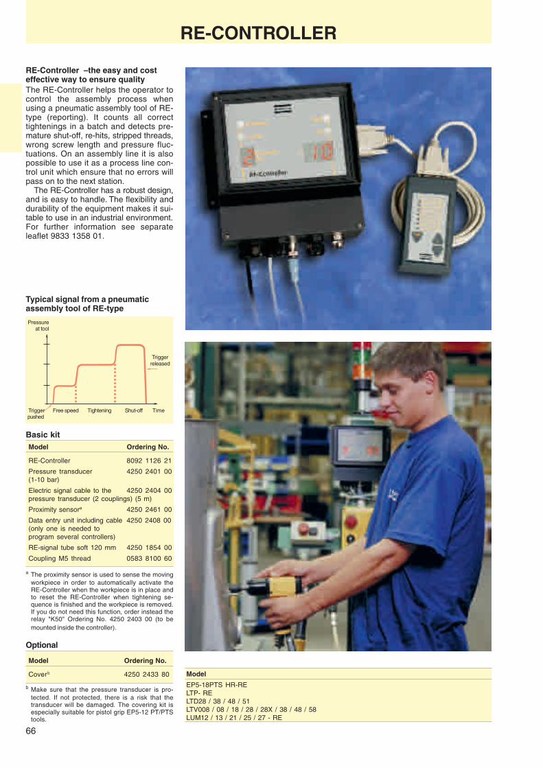
66
RE-Controller – the easy and costeffective way to ensure qualityThe RE-Controller helps the operator tocontrol the assembly process whenusing a pneumatic assembly tool of RE-type (reporting). It counts all correcttightenings in a batch and detects pre-mature shut-off, re-hits, stripped threads,wrong screw length and pressure fluc-tuations. On an assembly line it is alsopossible to use it as a process line con-trol unit which ensure that no errors willpass on to the next station.
The RE-Controller has a robust design,and is easy to handle. The flexibility anddurability of the equipment makes it sui-table to use in an industrial environment.For further information see separateleaflet 9833 1358 01.
RE-CONTROLLER
Basic kitModel Ordering No.
RE-Controller 8092 1126 21
Pressure transducer 4250 2401 00(1-10 bar)
Electric signal cable to the 4250 2404 00pressure transducer (2 couplings) (5 m)
Proximity sensora 4250 2461 00
Data entry unit including cable 4250 2408 00(only one is needed toprogram several controllers)
RE-signal tube soft 120 mm 4250 1854 00
Coupling M5 thread 0583 8100 60
a The proximity sensor is used to sense the movingworkpiece in order to automatically activate theRE-Controller when the workpiece is in place andto reset the RE-Controller when tightening se-quence is finished and the workpiece is removed.If you do not need this function, order instead therelay "K50" Ordering No. 4250 2403 00 (to bemounted inside the controller).
Pressureat tool
Triggerreleased
Trigger Free speed Tightening Shut-off Timepushed
Typical signal from a pneumaticassembly tool of RE-type
Model
EP5-18PTS HR-RELTP- RELTD28 / 38 / 48 / 51LTV008 / 08 / 18 / 28 / 28X / 38 / 48 / 58LUM12 / 13 / 21 / 25 / 27 - RE
Model Ordering No.
Coverb 4250 2433 80
Optional
b Make sure that the pressure transducer is pro-tected. If not protected, there is a risk that thetransducer will be damaged. The covering kit isespecially suitable for pistol grip EP5-12 PT/PTStools.

Right the first time...The Atlas Copco range of electric and batteryassembly tools, control systems and associatedsoftware packages define the global benchmarkin smart, cost-efficient and error-proof assemblymanagement. Browse the following pages and discover howour built-in error proofing functions can protectyou from costly operator errors: no more forgotten,loose or over tightened screws. Now you canreally know it’s right – first time!
Electricassembly toolsand systems
Contents PageTool key ......................................................... 68
Electric screwdrivers ..................................... 70
Industrial battery screwdrivers ....................... 75
Electric nutrunners Tensor DS........................ 80
Electric nutrunners Tensor S .......................... 86
DS 300 Drive ................................................. 94
Power Focus 3000 ......................................... 95
PowerMACS ................................................ 107
Bits and power sockets ............................... 116
Torque arms ................................................. 125

68
TOOL KEY
PF = Power Focus
Version
Generation
C = CompactG = GraphColour = Built in PC HW = Hardware
DN = DeviceNetPB = Profi busIB = InterbusMB = Modbus plusSize
7 = Motor size 3-79 = Motor size 8-9
PF 3 00 7 C DN HW
Power Focus
Electric
Shut-off
X = Generation
V = Right angleD = In-lineP = PistolF = FixtureO = Open EndC = Crowfoot
Torque
B = Ball retainerI = Female hexE = Extension be- tween gear train & front part
TechnologyDS = DigitorkNon-transducer
E T D DS 7 Y 10
Tensor DS
X 30 Z
7 = Motor size
Square drive size06 = 1/4", 10 = 3/8"13 = 1/2", 20 = 3/4"25 = 1", 38 = 1 1/2"
S = Signal light(Always included,ie not necessary)
OptionE = Extended spindleF = FanT = TelescopicFS = Flush socketHAD = Hold and DriveTM = Torque multiplierSH = Small headM = Mounting exten- sion for fi xtures between gear train & front partLO3 = Off-set with 3 gear wheelsLI3 = In-line with 3 gear wheelsSSW = Swivelling front part
The designator/ordering numbers of Atlas Copco assembly tools is a combination of letters and numbers indicating various properties and characteristics of the tool concerned.
Below is a guide showing the general signifi cance of each group of letters/numbers and specifi c guides to the individual tool types.
Toolkelectric eng.indd 68 2003-11-19, 12:40:16Cyanblå (processfärg)Magentaröd (processfärg)Gul (processfärg) Svart (processfärg)

69
Electric
Shut-off
X = Generation
V = Right angleD = In-lineP = PistolF = FixtureO = Open EndC = Crowfoot Torque
B = Ball retainerI = Female hexE = Extension be- tween gear train & front part
TechnologyS = SyncronizedmotorTransducer
E T D S 7 Y 10
Tensor S
X 30 Z
7 = Motor size
CTADSC = Controlled torqueT = TransducerA = Angle encoderD = Direct driveS = Signal light (Always included, ie not necessary)
OptionE = Extended spindleF = FanT = TelescopicFS = Flush socketHAD = Hold and DriveTM = Torque multiplierSH = Small headM = Mounting exten- sion for fi xtures between gear train & front partLO3 = Off-set with 3 gear wheelsLI3 = In-line with 3 gear wheels
Screwdrivers
TOOL KEY
Square drive size06 = 1/4", 10 = 3/8"13 = 1/2", 20 = 3/4"25 = 1", 38 = 1 1/2"
06 = 1/4", square drive10 = 3/8", square driveB10 = 3/8", sq. drive, ball retainer42 = 1/4", hex. bit driveQ = 1/4", hex. quick chuckFS10 = fl ush socket hex. 10 mm A/FFS13 = fl ush socket hex. 13 mm A/FFS5/16 = fl ush socket hex 5/16" hexHAD = Hold-and-drive
10B T V
B = Battery powered
T = Shut-off
V = Right angleD = In-line
28
Torque
ETB
Battery screwdriver,pistol grip
ETB
6i
Torquei = torch lightsL = low speed
BTV
Toolkelectric eng.indd 69 2003-11-19, 12:40:21Cyanblå (processfärg)Magentaröd (processfärg)Gul (processfärg) Svart (processfärg)

70
BATTERY AND ELECTRIC SCREWDRIVERS
Low voltage electric screwdriversand nutrunnersAtlas Copco offers a complete range ofelectric powered assembly tools inclu-ding battery screwdrivers and nutrunners,small transformer powered screwdriversand advanced current controlled screw-drivers, nutrunners and assembly systems.
Low voltage electric motors have theirobvious place as power source for batteryscrewdrivers and nutrunners. Low voltageelectric screwdrivers – powered fromthe mains via a transformer and rectifier– are many times also preferred forsmall screws tightening in industrialapplications where a clean and low-noiseenvironment is a primary demand. AtlasCopco’s wide experience in design ofindustrial assembly tools, from the highperformance air screwdrivers and nut-runners with mechanical shut-off clutchto the sophisticated current controlledelectric assembly tools, also forms anatural platform for the development ofindustrial battery tools and low voltagescrewdrivers.Eliza shut-off electric screwdriversThe Eliza range of low voltage screw-drivers is recognised for reliability inoperation. The basic design has remainedthe same for many years but up-gradeshave been made on premium values
such as ESD certification as standard,new soft stop models and soft touchgrip – features that improve productquality and increase operator comfort.The selection of a low-voltage system isalso a matter of maintaining highestlevel of safety against electric shock inoperation and maintenance. The Elizascrewdrivers cover the capacity rangefrom 0.03 to 3.4 Nm torque.Battery screwdrivers and nutrunnersFreedom to move without being ham-pered by an air hose or a electric cableand the safety risk of jammed highvoltage cords have led to a boost indemand for battery tools from craftsmenand lately also from the productionindustry. Atlas Copco has put the indus-trial touch to the battery assembly toolsand is today the leading supplier ofindustrial battery tools to themotor vehicle industryand other assemblyline works. The
range includes ETB pistol screwdriversup to 10 Nm and BTV angle screwdriversand nutrunners up to 28 Nm.

71
ELI16-SS
ELI06
ELI26P
ELI36
ELI16SS ELI16
20
1000080006000400020000
60
40
100
80
120
0
ELECTRIC SCREWDRIVERS
Screw size M1 – M4Torque range 0.03 – 3.4 NmThe Eliza electric screwdrivers are theideal choice in the electronic industry,among small components manufacturers,the appliance industry and other industrieswhere cleanliness in operation, ease ofinstallation, low noise level and limitedtotal investment are essential.❏ Safe – Via a transformer the tools are
powered by a mere 30 VDC, whichmeans that there is no risk fordangerous electric chock in operationor during service and maintenance.
❏ Ergonomic – Soft touch grip, lowweight, small dimensions, perfectbalance, a minimum of vibration andreaction force.
❏ Accurate – Combined mechanicalclutch and electric shut-off providesfor excellent torque repeatability.
❏ High productivity – Careful balancebetween speed and torque, electricallyand mechanically dimensioned forcontinuous production, meet the highestdemands for production rate andservice life.
❏ ESD certified – Dissipative plasticcasing and electric connection of thetool body to ground potential preventstatic electricity from being built up inor on the face of the tool and dischargeto sensitive electronic components.
❏ Soft stop options – Special modelsare available for those applicationswhere shock sensitive electronicdevices might be harmed by thevibrations from the clutch action. Thesmooth shut-off also reduces the jerkto the hand of the operator.
Torque range Free WeightScrew Soft joint speed Length Bit
Model capacity Nm in lb r/mina kg lb mm drive Ordering No.
Trigger start screwdrivers (excl. control box)ELI006 M1.0-M2.0 0.03-0.2 0.3-1.7 1000 0.35 0.8 183 Ø 4 mm 8431 0156 06ELI06 M1.2-M2.5 0.05-0.5 0.4-4.4 1000 0.38 0.8 197 1/4 hex 8431 0156 00ELI16 M2-M3 0.15-1.6 1.3-14 825 0.6 1.4 235 1/4 hex 8431 0156 18ELI26 M2.5-M4 0.3 -2.5 2.6-22 700 0.7 1.5 255 1/4 hex 8431 0156 26ELI36 M2.5-M4 0.4 -3.4 3.5-30 700 0.6 1.4 235 1/4 hex 8431 0156 34Push start screwdrivers (excl. control box)ELI16-P M2-M3 0.15-1.6 1.3-14 825 0.6 1.4 235 1/4 hex 8431 0156 42ELI26-P M2.5-M4 0.3 -2.5 2.6-22 700 0.7 1.5 255 1/4 hex 8431 0156 59ELI36-P M2.5-M4 0.5 -1.8 4.3-16 1500 0.6 1.4 235 1/4 hex 8431 0156 63Soft-stop screwdrivers with trigger start (excl. control box)ELI06-SS M1.4-M2.5 0.1 -0.44 0.9-3.9 1000 0.4 0.9 197 1/4 hex 8431 0156 67ELI16-SS M2-M3 0.25-1.3 2.2-11 825 0.6 1.4 235 1/4 hex 8431 0156 75ELI26-SS M2.5-M3 0.5 -1.7 4.4-15 700 0.7 1.5 255 1/4 hex 8431 0156 83Control boxes ESD certifiedCBE50 Controller for single ELI006, 06, 16 or 26 models 8431 0164 09CBE65 Controller for single ELI36 models 8431 0164 17CBE50-S Slow start controller for single ELI006, 06, 16 or 26 models 8431 0164 25TransformersPFS60-ESD For single ELI006, 06, 16 or 26 models - 230V. ESD certified 8431 0160 11PFS60-ESD-115 For single ELI006, 06, 16 or 26 models - 115V. ESD certified 8431 0160 13PFS151 For ELI36 models and power network - 230V. Not ESD certifiedab 8431 0160 15PFS151-115 For ELI36 models and power network - 115V. Not ESD certifiedab 8431 0161 15Power packages ESD certifiedCTB50 Transformer/controller for single ELI006, 06, 16 or 26 models 8431 0162 01CTB65 Transformer/controller for single ELI36 models 8431 0162 19CTB100 Transformer/controller for two ELI006, 06, 16 or 26 models 8431 0162 27
a In EPA (Electrostatic Protected Area) use power package CTB65 for ELI36.b PFS151 has double socket connection.
Shock Response Spectrum
Acc
eler
atio
nFrequency

72
PFS151
PFS60
ELECTRIC SCREWDRIVERS
Electronic controlDespite the advanced electronic control ofthe tools the Eliza screwdrivers are smalland light. This has been achieved bylocating the electronic components in aseparate control box. A number of diffe-rent controllers or combined controller/transformer offers a variety of installationoptions and functions. For a complete in-stallation the CBE controllers and PFStransformers or the CTB "Power Packs"must be specified separately.
Slow start controllerHigh screwdriver speed is sometimescritical for both bit engagement and safescrew entering. With the optional controller,offering adjustable starting speed andtime, the problems can be eliminated.
TransformerIn the basic set-up with controller andseparate transformer, the transformer isused to lower the mains voltage to 22VAC before being rectified in the controlbox. The PFS60 transformer powerssizes ELI006, 06, 16, and 26. The ELI36must have the bigger PFS151 trans-former. The PFS151 transformer can beused for simultaneously powering se-veral Eliza screwdrivers depending onsize.
One unit installationThe combined transformer/controller unitsCTB simplify installation.
For ELI36 screwdrivers the CTB65must be used as power supply whereESD approval is required.
The CTB Power Packs offer selectionof low-speed mode for those applicationswhere a high run-down speed mightdistort the thread, e.g. tightening self-drilling screws in plastic.
The CTB100 has conectors for simul-taneously powering two screwdrivers ofsizes ELI006, 06, 16, and 26.
For ELI06, ELI16 and ELI26.
Powers simultaneouslyPower
Model ELI006/06 ELI16/26 ELI36 VA
PFS60 2 1 - 60PFS151 6 3 2 150
PFS60 – Single socket connection.PFS151 – Double socket connection.
100%
15%
Speed
Normal start
Slow start
1 2 3 4 seconds

73
Screw pick-up systemPicking and positioning of screws aremany times crucial for productivity insmall screw assembly. The Eliza rangeof optional equipment offers a vacuumpick-up system to simplify pre-tighteningpreparations. The system consists of avacuum pump, adapters for the screw-driver a shaker tray and grids for differentscrew dimensions.The system components are not ESDcertified.
Vacuum pick-up adaptersAll Eliza screwdrivers can be equippedwith vacuum pick-up adapters ready toconnect to a vacuum pump. Theadapters are delivered withoutnozzles.
ACCESSORIES
Push start ELI06The push start function is also availablefor the ELI06 size by mounting a slidinggrip sleeve replacing the standard triggerstart.(Not ESD certified)Ordering No. 4220 0106 00
Cable optionsThe tools are supplied with a cable forconnection to the controller/power supplyunit. Connecting one or two extensioncables of 3 m length to the standardcable increases the distance betweentool and control box up to 8 m.(ESD certified)Ordering No. 4220 0138 01
A spiral cable of 1.3 m length, extractedmax 2.4 m, can also be ordered sepa-rately.(Not ESD certified)Ordering No. 4220 0347 00
Pistol gripA pistol grip handle is available for modelsELI16, 26 and 36.(ESD certified)Ordering No. 4220 0051 00
Shaker trayConsists of a rubber box. A variety ofinterchangeable rubber grid plates canbe ordered separately.Ordering No. 4220 0054 00
Grid
Screw Screwsize sizemm Ordering No. mm Ordering No.
1.2/1.4 4220 0055 00 2.6 4220 0059 001.7 4220 0056 00 3.0 4220 0060 002.0 4220 0057 00 4.0 4220 0061 002.3 4220 0058 00
CONNECTORS ISO standardTo build your own 22 V AC network. Withthese components and an ordinary twocore cable, min 1.5 mm2, you can quicklyarrange the electric supply for a series ofscrewdrivers.
SELECTED SERVICE KITS
Model Ordering No.
Vacuum pump 4220 0062 00Vacuum pick-up adapter for ELI06a 4220 0052 00Vacuum pick-up adapter for ELI16/26/36a 4220 0053 00
Nozzle blank Ø 8 mm for ELI06 4220 0067 03Nozzle blank Ø 8 mm for ELI16/26/36 4220 0070 03Nozzle blank Ø 14 mm for ELI16/26/36 4220 0072 03
a Not ESD certified.
Angle headEliza screwdriver models ELI16, 26 and36 can be equipped with a 90o anglehead for access in cramped quarters.Ordering No. 4220 0425 80
Nozzle blanksThe following brass blanks are available.They must be machined to fit the specificscrew to be picked up.
Designation Ordering No.
Male plug 4220 0095 00
2-way female socket 4220 0096 00For wall mounting(Not ESD certified)
Small BrushModel parts kit kit
ELI06 4220 0030 90 4220 0022 90ELI16/26/36 4220 0049 90 4220 0041 90ELI16P/26P 4220 0049 90 4220 0041 90

74
ESD – Electrostatic discharge – isincreasingly recognised as a majorcause of damage to electronic devices.ISO 9000 quality certification drives theneed for proper ESD control programsand IEC international standard definesthe risk potential and protection for thehandling of electronic components.
Industrial tools – source of damageby ESDIndustrial screwdrivers used in theassembly of electronic components anddevices incorporating microelectronicsare naturally critical items with regard toESD risk potential.❏ The body of the tool, whether air or
electrically powered, can hold staticelectricity and discharge to the workpiece via the screwdriver bit.
❏ The plastic materials used forinsulation of electrical tools and forconvenience and thermal isolation onair tools are sources for generatingand holding of static charges andalso prevent the tool body from beingbrought to ground potential throughthe hand of the operator.
❏ The plastic material used in electriccords and connectors as well as theplastic air hoses are also liable tobuild up electrostatic fields that mightdischarge to any object that comesclose enough.
ESD certified screwdriversAtlas Copco offers ESD certified tools inthe standard range of screwdrivermodels most frequently used in theelectronic industries. This means aguarantee against damage of electroniccomponents by an uncontrolled electro-static discharge (ESD) from the tools.
Conformity to the requirements of IEC61340-5-1 standard proposal is approvedby SP, Swedish National Testing andResearch Institute. In practice it certifiesthat the material of the equipment at nopoint will hold an electrostatic potentialabove 100 V for more than 2 seconds.
The Atlas Copco ESD protectionconcept has today been brought intoboth the low voltage electric screw-drivers type ELI in the capacity rangefrom 0.05 to 3.5 Nm and the small straightscrewdrivers LUM10 and LUM21 withtorque output between 0.1 and 4.5 Nm.
Air tools installation for ESD protectionThe air-powered screwdrivers must beset up in a way that the tool body willdischarge to ground in order to meetthe ESD approval standard. Thesimplest way to do this is to install thetools at the work place with the specialAtlas Copco conductive air hose thatgrants that no electrostatic charges arebuilt up at any face of the screwdriver orthe bit used.
You will find the ESD approved screw-drivers for airpowered tools on pages30-33 and pages 71-73 for electric tools.
ESD APPROVED SCREWDRIVERSAir-powered and low-voltage electric screwdrivers

75
BTV11
BTV7
BTV28
Camprofile
Soundoscillation
Click signature
INDUSTRIAL BATTERY SCREWDRIVERSShut-off control
Screw size M3 – M6Torque range 0.9 – 28 NmFor productivity reasons air tools havegenerally been preferred in industrialapplications due to the favourablepower-to-weight ratio of the air motor.On industrial assembly lines today, how-ever, the mode of operation has changedand many screws are best tightenedwith a battery tool that allows freedomto move along a running production line.
To meet the demands from industrialoperation Atlas Copco has developedits own range of industrial battery screw-drivers, utilising know-how from buildingaccurate and reliable industrial screw-drivers and combining this with new inno-vative technique in battery motor control.
BTV – battery angle screwdriversThe BTV battery angle screwdriver uti-lises the best of available techniques toallow a lightweight and handy batterytool, an extensive number of tighteningsbefore recharging the battery, a servicelife that matches any other power tooland accuracy with electronic precision.Where portability is essential on yourassembly line the BTV is the ideal matchoffering:❏ Torque accuracy – Excellent torque
repeatability, low mean shift and lowreaction force.
❏ Movability – Freedom to move withoutair hose or electric cord to provide forthe power. Freedom to work insideclosed compartments, e.g. inside avehicle.
❏ Work protection – Car body finishfree from scratches from hoses andcords.
❏ Work place arrangement – Highflexibility and rapid set-up.
❏ A safe work place – Free from inter-ference of air hoses and risk of jam-med electric cords.
❏ Ergonomics – Low sound level, cleanfor the operator and his workingenvironment.
ACD control – reliability, low wear andeasy serviceThe ACD, Acoustic Clutch Detection, inthe BTV battery tool uses a sophisticatedelectronic identification of the specificsound signature of the click when theclutch releases to short-circuit the elec-tric motor and brake the rotation whentightening is finished. The lack of wearingmechanical switches, magnets and sen-sitive electronic components and the elimi-nation of wiring between the mechanicalclutch and the electronic control cardmeans a considerable improvement inreliability, wearing properties and service-ability.
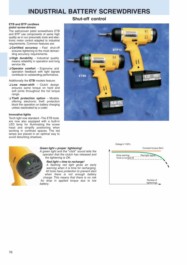
76
ETB6
BTP12
Green light = proper tightening!A green light and the “ click” sound tells the
operator that the clutch has released andthe tightening is OK.Red light = time to recharge!A flashing red light gives an earlywarning when it is time for recharging.All tools have protection to prevent start
when there is not enough batterycharge. This means that there is no risk
for drop in applied torque due to lowbattery.
INDUSTRIAL BATTERY SCREWDRIVERSShut-off control
ETB and BTP cordlesspistol screw-driversThe well-proven pistol screwdrivers ETBand BTP use components of same highquality as in our pneumatic tools and elec-tronic motor control adapted to industrialrequirements. Common features are:❏ Certified accuracy – Fast shut-off
ensures tightening to the most deman-ding accuracy requirements.
❏ High durability – Industrial qualitymeans reliability in operation and longservice life.
❏ Operator comfort – Ergonomy andoperation feedback with light signalscontribute to outstanding performance.
Additionally the ETB models feature:❏ Low mean-shift – Clutch design
ensures same torque on hard andsoft joints throughout the full torquerange.
❏ Theft protection option – Modelsoffering electronic theft protectionblock the operation on battery chargingunless reactivated by a coder.
Early warning Red light signalTools is turned off
Voltage V 100%
Number oftightenings
Constant torque (Nm)
Innovative lightsTorch light now standard – The ETB toolsare now also equipped with a built-inLED lamp for illuminating the screwhead and simplify positioning whenworking in confined spaces. The ledlamps are placed in an optimal way toavoid disturbing shadows.

77
EPA6
The ErgoPulse conceptEPA – battery pulse screwdriversThe Atlas Copco range of battery toolsalso includes the ErgoPulse screwdriverutilising the pulse concept; yet anothercombination of industrial tool techniques.❏ High speed – Gear-less operation
means high rundown speed andshort cycle times.
❏ High torque, low reaction – Thepulse technique allows high torquewithout any reaction force to theoperator.
❏ Shut-off function – A timer shut-offdevice eliminates operator influenceon the tightening torque.
❏ Theft protection option – Also theEPA is available in a model withelectronic theft protection.
INDUSTRIAL BATTERY SCREWDRIVERSShut-off control
Recommended Free speed WeightScrew torque range excl. batttery PROT versionsize 9.6 V 12 V 14.4 Tool only tool only
Model mm Nm in lb r/min r/min r/min kg lb Ordering No. Ordering No.
BTVBTV7-6 M3-M5 2 - 7 18 - 62 350 450 – 1.4 3.0 8431 0261 42 8431 0261 43BTV7-42 M3-M5 2 - 7 18 - 62 350 450 – 1.4 3.0 8431 0261 46 8431 0261 47BTV7-Q M3-M5 2 - 7 18 - 62 350 450 – 1.4 3.0 8431 0261 50 8431 0261 51BTV11-6 M4-M6 4 - 11 36 - 97 300 380 – 1.4 3.0 8431 0261 62 8431 0261 63BTV11-42 M4-M6 4 - 11 36 - 97 300 380 – 1.4 3.0 8431 0261 66 8431 0261 67BTV11-Q M4-M6 4 - 11 36 - 97 300 380 – 1.4 3.0 8431 0261 70 8431 0261 71BTV11-10 M4-M6 4 - 11 36 - 97 300 380 – 1.4 3.0 8431 0261 74 8431 0261 75BTV15-6 M6 8 - 15 70 - 132 – 340 410 1.7 3.7 8431 0261 81 8431 0261 82BTV15-42 M6 8 - 15 70 - 132 – 340 410 1.7 3.7 8431 0261 84 8431 0261 85BTV15-Q M6 8 - 15 70 - 132 – 340 410 1.7 3.7 8431 0261 87 8431 0261 88BTV15-10 M6 8 - 15 70 - 132 – 340 410 1.7 3.7 8431 0261 90 8431 0261 91BTV28-42 M8 15 - 28 132 - 248 – 210 260 1.8 4.0 8431 0261 93 8431 0261 94BTV28-10 M8 15 - 28 132 - 248 – 210 260 1.8 4.0 8431 0261 96 8431 0261 97BTV28-B10 M8 15 - 28 132 - 248 – 210 260 1.8 4.0 8431 0261 99 8431 0262 00BTV28-Q M8 15 - 28 132 - 248 – 210 260 1.8 4.0 8431 0262 02 8431 0262 03
ETB – screwdrivers with shut-off. Pistol grip modelsETB4i M3-M5 0.9 - 4.5 8 - 40 800 970 – 1.2 2.6 8431 0272 46 8431 0272 47ETB6i M3-M5 1.9 - 7 16 - 62 520 620 – 1.2 2.6 8431 0272 41 8431 0272 44ETB6Li M3-M5 1.9 - 7 16 - 62 290 360 – 1.2 2.6 8431 0272 48 –ETB10i M4-M6 3 - 10 26 - 90 360 480 – 1.2 2.6 8431 0272 42 8431 0272 43(ETB6/10: For low torque 1-3.5 Nm use optional clutch spring 4210 3690 90. NOTE: The torque marking system is adapted to standard spring)
BTP – screwdriversBTP6 M3-M5 1.5 - 6 13 - 53 390 – – 1.3 3.7 8431 0266 50 –BTP12 M5-M6 6 - 12 53 - 110 – 360 – 1.3 3.9 8431 0266 52 –
ErgoPulse – hydraulic impulse screwdriversEPA6 M6 5 - 13 44 - 115 3000 – – 1.2 3.7 8431 0262 48 8431 0262 49
a 9.6 V, 2.0 Ah battery for all models except BTP12.
All models have 1/4" female hexagon drive for bitswith quick change chuck.

78
The mounting bracket can fit up to fivechargers or four chargers and a decoder.
WeightVoltage Capacity gram Ordering No.
Battery 9.6 V 1.4 Ah 530 4210 3680 001.7 Ah 550 4210 3680 012.0 Ah 570 4210 3680 02
12 V 1.4 Ah Flat pack 500 4210 3680 032.0 Ah 730 4210 3680 05
14.4 V 2.8 Ah 800 4210 3680 06
Spare Battery housing 9.6 V 4210 3680 80
Modular battery system❏ Battery standard – Basic battery
standard for all tools except the BTP12is 9.6 V. BTV and ETB can also bepowered with a 12 V battery to increasespeed by approximately 25%.
Colour torque systemThe Atlas Copco colour torque system givesyou an easily visible torque marking system forall your ETB tools. Select a unique colourcombination for each torque level used on yourassembly line.
Angle head for ETB (gear ratio 1:1.56)NOTE: Torque will increase 50%when angle head is used.
1/4" female hexagon 4210 1875 88drive for bits
3/8" square drive for sockets 4210 1875 89
1/4" square drive for 4110 1404 76sockets max 7 Nm
30o angle head for ETB (up to 7 Nm)Quick change chuck 4110 1436 84for female bits
Square drive kit 1/4" for EPA6 4210 2518 90
❏ Charger standard – Chargers are ofpulse types that ensures long batterylife. Standard charger included in toolkits is of the quick charge type.
❏ Multiple charger system – Byassembly of standard chargers on acommon bracket a multiple chargersystem can be built up. A mountingbracket for up to five chargers or fourchargers and a theft decoder is avai-lable to order.
INDUSTRIAL BATTERY SCREWDRIVERSShut-off control
Pulse chargers15/23 mina (1.4/2.0 Ah) 230/240 V 4210 3675 0025/36 min (1.4/2.0 Ah) 110/120 V 4210 3675 011/1.3 hour (1.4/2.0 Ah) 230/240 V 4210 3676 00
Mounting bracket for multiple chargerEuro-contact 230/240 V 4210 3677 00US-contact 110/120 V 4210 3677 01NOTE: Chargers are bought separarely.
Decoder kitDecoder kit 230/240 V 4210 3679 90Decoder kit 110/120 V 4210 3679 91
Protection cover 4210 3810 00
Suspension yokeETB 4211 5000 80BTV 4211 5080 80
Pulse charger Decoder
Protective cover
Batteries
Colour torque marking rings
Red 4210 3795 02Green 4210 3795 04Blue 4210 3795 06Orange 4210 3795 08
a Not for 14.4 V battery.

79
TENSORThe new generation electrically controlled nutrunners
A complete rangeThe Tensor electrical tool range covers all assembly line require-ments for safety- and quality-critical fasteners. The Tensor S isa world beater in the field of transducerized power tools.Featuring the innovative S motor, based on Atlas Copco’sproprietary technology, the Tensor S has rapidly revolution-ized the assembly industry.
The first true non-transducerized electric power tool, theTensor DS, makes it feasible to equip an entire facility withelectrical tools.
Productivity gainsCompared with conventional nutrunners, Tensor tools offer su-perior spindle performance. Faster speeds and high cyclerates mean increased productivity and reduced assemblytimes.Green light for qualityForgotten screws and faulty fasteners are errors that canjeopardise your assembly quality. The green light from theTensor tool assures that all screws were tightened and thatthe joint was OK.Exceptional ergonomicsErgonomics excellence was a key priority in developing theTensor tools. The balance, grip and low weight make them afavourite on the assembly line.Tightens customer satisfactionAll industries with assembly operations have one thing incommon – demanding customers who insist on quality andvalue for money. The Tensor range has been developed togive you the benefits of controlled tightening and advancedelectric systems throughout your assembly operations.Tensor tool configurationsThe Tensor family comprises a broad range of tool configu-rations to cover every hand-held or fixtured application foundin an assembly plant. Available for torques ranging from 1 to4,000 Nm, and in 8 different configurations, the Tensor rangeof multi-torque electrical tools can be used to equip an entirefacility.
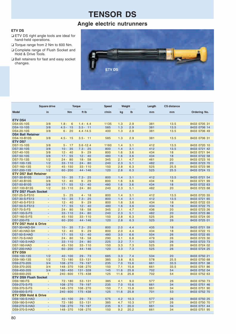
80
ETV DS
TENSOR DSAngle electric nutrunners
ETV DS❏ ETV DS right angle tools are ideal for
hand-held operations.❏ Torque range from 2 Nm to 600 Nm.❏ Complete range of Flush Socket and
Hold & Drive Tools.❏ Ball retainers for fast and easy socket
changes.
Square drive Torque Speed Weight Length CS distance
Model in Nm ft lb r/min kg lb mm mm Ordering No.
ETV DS4DS4-05-10S 3/8 1.8 - 6 1.4 - 4.4 1135 1.3 2.9 381 13.5 8433 0705 31DS4-10-10S 3/8 4.5 - 15 3.5 - 11 585 1.3 2.9 381 13.5 8433 0706 14DS4-20-10S 3/8 6 - 20 4.4 -14.5 400 1.3 2.9 381 13.5 8433 0706 49DS4 Ball RetainerDS4-10-B10S 3/8 4.5 - 15 3.5 - 11 585 1.3 2.9 381 13.5 8433 0706 31ETV DS7DS7-15-10S 3/8 5 - 17 3.6 -12.4 1160 1.4 3.1 412 13.5 8433 0720 10DS7-30-10S 3/8 10 - 35 7.3 - 25 800 1.4 3.1 412 13.5 8433 0721 42DS7-40-10S 3/8 12 - 40 9 - 29 800 1.6 3.6 434 18 8433 0721 94DS7-50-10S 3/8 17 - 55 12 - 40 480 1.6 3.6 434 18 8433 0722 58DS7-70-13S 1/2 24 - 80 18 - 58 345 2.1 4.7 461 20 8433 0723 16DS7-100-13S 1/2 33 - 110 24 - 80 240 2.3 5.1 482 20 8433 0723 70DS7-160-13S 1/2 45 - 150 33 - 110 150 2.8 6.3 525 25.5 8433 0723 98DS7-200-13S 1/2 60 - 200 44 - 146 120 2.8 6.3 525 25.5 8433 0724 15ETV DS7 Ball RetainerDS7-30-B10S 3/8 10 - 35 7.3 - 25 800 1.4 3.1 412 13.5 8433 0721 54DS7-40-B10S 3/8 12 - 40 9 - 29 800 1.6 3.6 434 18 8433 0721 99DS7-50-B10S 3/8 17 - 55 12 - 40 480 1.6 3.6 434 18 8433 0722 63DS7-100-B13S 1/2 33 - 110 24 - 80 240 2.3 5.1 482 20 8433 0723 68ETV DS7 Flush SocketDS7-25-S-FS10 - 5 - 25 4 - 18 800 1.4 3.1 412 13.5 8433 0720 55DS7-30-S-FS13 - 10 - 35 7.3 - 25 800 1.4 3.1 412 13.5 8433 0721 65DS7-40-S-FS13 - 12 - 40 9 - 29 800 1.6 3.6 434 18 8433 0722 03DS7-50-S-FS13 - 17 - 55 12 - 40 480 1.6 3.6 434 18 8433 0722 75DS7-70-S-FS - 24 - 80 18 - 58 345 2.1 4.7 436 20 8433 0723 26DS7-100-S-FS - 33 - 110 24 - 80 240 2.3 5.1 482 20 8433 0723 86DS7-160-S-FS - 45 - 150 33 - 110 150 2.8 6.3 525 26 8433 0724 00DS7-200-FS - 60 - 200 44 - 146 120 2.8 6.3 525 26 8433 0725 01ETV DS7 Hold & DriveDS7-30-HAD-SH - 10 - 35 7.3 - 25 800 2.0 4.4 435 18 8433 0721 59DS7-40-HAD-SH - 12 - 40 9 - 29 800 2.0 4.4 434 18 8433 0722 15DS7-50-S-HAD - 17 - 55 12 - 40 480 3.0 6.6 504 26 8433 0722 65DS7-70-S-HAD - 24 - 80 18 - 58 290 3.1 6.8 479 26 8433 0723 30DS7-100-S-HAD - 33 - 110 24 - 80 225 3.2 7.1 525 26 8433 0723 73DS7-160-HAD - 45 - 150 33 - 110 150 3.3 7.3 525 26 8433 0724 02DS7-200-HAD - 60 - 200 44 - 146 120 3.3 7.3 525 26 8433 0724 25ETV DS9DS9-100-13S 1/2 40 - 100 29 - 73 685 3.3 7.4 534 20 8433 0750 21DS9-180-13S 1/2 72 - 180 53 - 131 385 3.8 8.5 578 25.5 8433 0750 68DS9-270-20S 3/4 108 - 270 79 - 197 235 7.0 15.6 661 33.5 8433 0751 38DS9-370-20S 3/4 148 - 370 108 - 270 150 7.1 15.8 661 33.5 8433 0751 86DS9-450-20S 3/4 180 - 450 131 - 328 145 11.6 25.8 702 54 8433 0752 04DS9-600-25S 1 240 - 600 175 - 438 125 11.6 25.8 702 54 8433 0752 63ETV DS9 Flush SocketDS9-180-FS - 72 - 180 53 - 131 385 4.1 9.0 577 26 8433 0750 73DS9-270-S-FS - 108 - 270 79 - 197 235 7.0 15.6 661 34 8433 0751 46DS9-370-S-FS - 148 - 370 108 - 270 150 7.1 15.8 661 34 8433 0751 90DS9-600-S-FS - 240 - 600 175 - 438 125 11.6 25.8 701 53 8433 0752 70ETV DS9 Hold & DriveDS9-100-S-HAD - 40 - 100 29 - 73 575 4.2 10.3 577 26 8433 0750 25DS9-180-S-HAD - 72 - 180 53 - 131 385 4.7 10.3 577 26 8433 0750 70DS9-270-S-HAD - 108 - 270 79 - 197 235 9.1 20.0 661 34 8433 0751 44DS9-370-S-HAD - 148 - 370 108 - 270 150 9.2 20.2 661 34 8433 0751 95

81
ETD DS
Square drive Torque Speed Weight Length CS distance Spline/
Model in Nm ft lb r/min kg lb mm mm Mounting Ordering No.
ETD DS4DS4-05-10S 3/8 2 - 5 1.5 - 3.6 1315 1.1 2.5 380 28 – / 1 8433 0710 29DS4-10-10S 3/8 4 - 14 3 - 10 620 1.1 2.5 380 28 – / 1 8433 0710 52
ETD DS4 TelescopicDS4-05-10ST 3/8 2 - 5 1.5 - 3.6 1315 1.3 2.9 418 28 2 / 2 8433 0710 37DS4-10-10ST 3/8 4 - 14 1.5 - 3.6 620 1.3 2.9 418 28 2 / 2 8433 0710 73
ETD DS4 Female HexDS4-02-I06S 1/4 1.0 - 2.5 0.7 - 1.8 2942 1.1 2.5 371 21.5 – / 1 8433 0710 22DS4-05-I06S 1/4 2 - 5 1.5 - 3.6 1310 1.1 2.5 371 28 – / 1 8433 0710 26
ETD DS7DS7-20-10S 3/8 6 - 20 4.4 - 14.5 1240 1.4 3.1 411 28 – / 1 8433 0730 23DS7-30-10S 3/8 10 - 35 7.3 - 25 745 1.4 3.1 411 28 – / 1 8433 0730 88DS7-50-13S 1/2 17 - 55 12 - 40 540 1.9 4.2 456 28 2 / 2 8433 0731 12DS7-70-13S 1/2 21 - 70 15 - 51 370 2.2 4.9 477 28 2 / 2 8433 0731 31DS7-90-13S 1/2 28 - 95 21 - 69 275 2.2 4.9 477 28 2 / 2 8433 0731 45DS7-120-13S 1/2 38 - 125 28 - 91 225 2.2 4.9 477 28 2 / 2 8433 0731 84
ETD DS7 TelescopicDS7-20-10ST 3/8 6 - 20 4.4 - 14.5 1240 1.5 3.3 449 28 2 / 2 8433 0730 44DS7-30-10ST 3/8 10 - 35 7.3 - 25 745 1.5 3.3 449 28 2 / 2 8433 0731 05DS7-50-13ST 1/2 17 - 55 12 - 40 540 2.1 4.7 483 28 3 / 5 8433 0731 24DS7-70-13ST 1/2 21 - 70 15 - 51 370 2.4 5.4 504 28 3 / 5 8433 0731 40DS7-90-13ST 1/2 28 - 95 21 - 69 275 2.4 5.4 504 28 3 / 5 8433 0731 52DS7-120-13ST 1/2 38 - 125 28 - 91 225 2.4 5.4 504 28 3 / 5 8433 0731 96
ETD DS9DS9-100-13S 1/2 40 - 100 29 - 73 715 3.0 6.7 529 32 2 / 2 8433 0756 42DS9-150-13S 1/2 60 - 150 44 - 110 455 3.2 7.1 544 32 2 / 2 8433 0757 54DS9-200-13S 1/2 80 - 200 58 - 146 340 3.2 7.1 544 32 2 / 2 8433 0758 71DS9-450-20S 3/4 180 - 450 131 - 328 125 7.4 16.3 639 40.5 6 / 8 8433 0760 71
ETD DS9 TelescopicDS9-100-13ST 1/2 40 - 100 29 - 73 715 3.2 7.1 557 32 3 / 5 8433 0756 92DS9-150-13ST 1/2 60 - 150 44 - 110 455 3.4 7.6 572 32 3 / 5 8433 0758 03DS9-200-13ST 1/2 80 - 200 58 - 146 340 3.4 7.6 572 32 3 / 5 8433 0759 11DS9-270-20ST 3/4 108 - 270 79 - 197 225 6.0 13.4 653 36 6 / 8 8433 0760 55DS9-450-20ST 3/4 180 - 450 131 - 328 125 7.6 17 689 40.5 6 / 8 8433 0760 88DS9-600-20ST 3/4 240 - 600 175 - 438 110 7.6 17 689 40.5 6 / 8 8433 0761 35DS9-1000-25ST 1 400 -1000 292 - 730 68 12.5 28 824 47 7 / 11 8433 0763 63DS9-2000-38ST 1 1/2 600 -2000 438 -1460 34 22.5 50.4 824 68 8 / 12 8433 0764 20
ETD DS9 SwivellingDS9-450-20SSW 3/4 180 - 450 79 - 197 125 7.8 17.4 639 40.5 6 / 8 8433 0760 94DS9-600-20SSW 3/4 240 - 600 175 - 438 110 7.8 17.4 639 40.5 6 / 8 8433 0761 59
ETD DS❏ ETD DS inline tools. The low torque
series is ideal for hand-held benchassembly. The high torque tools arewell suited for fixtured applications.
❏ Torque range from 1 Nm to 2000 Nm.❏ Telescopic spindles for fixtured appli-
cations.❏ Female Hex drives for bits.❏ Swivelling front parts for low reaction
force.
TENSOR DSStraight electric nutrunners

82
ETP DS
ETP DS SSW
ETP DS❏ ETP DS pistol grip tool for both hand-
held and fixtured applications.❏ Torque range from 2 Nm to 2000 Nm.❏ Telescopic spindles for fixtured appli-
cations.❏ Swivelling front parts for low reaction
force.❏ Female Hex drives for bits.
Square drive Torque Speed Weight Length CS distance Spline/
Model in Nm ft lb r/min kg lb mm mm Mounting Ordering No.
ETP DS4DS4-05-06S 1/4 2 - 5 1.5 - 3.6 1310 1.1 2.5 193 21.5 – / – 8433 0708 76DS4-10-06S 1/4 3.5 - 12 2.5 - 8.8 660 1.1 2.5 193 21.5 – / – 8433 0708 92DS4-10-10S 3/8 3.5 - 12 2.5 - 8.8 660 1.1 2.5 193 21.5 – / – 8433 0709 06ETP DS4 Female HexDS4-02-I06S 1/4 1.0 - 2.5 0.7 - 1.8 2942 1.1 2.5 201 21.5 – / – 8433 0708 57DS42-02-I06 1/4 1.0 - 2.5 0.7 - 1.8 2950 0.9 2.0 188 21.3 – / – 8433 0708 40DS4-05-I06S 1/4 2 - 5 1.5 - 3.6 1310 1.1 2.5 201 21.5 – / – 8433 0708 61DS42-05-I06 1/4 2 - 5 1.5 - 3.6 1770 0.9 2.0 188 21.3 – / – 8433 0708 69DS4-07-I06S 1/4 2.1 - 7 1.5 - 5.1 905 1.1 2.5 201 21.5 – / – 8433 0708 80DS4-10-I06S 1/4 3.5 - 12 2.5 - 8.8 660 1.1 2.5 201 21.5 – / – 8433 0708 83DS42-10-I06 1/4 3.5 - 12 2.5 - 8.8 905 1.0 2.2 188 21.3 – / – 8433 0708 87
ETP DS7DS7-20-10S 3/8 6 - 20 4.4 - 14.5 1240 1.6 3.6 273 22 – / 1 8433 0726 36DS7-30-10S 3/8 10 - 35 7.3 - 25 750 1.6 3.6 273 22 – / 1 8433 0726 53DS7-50-13S 1/2 17 - 55 12 - 40 540 1.9 4.2 318 21.5 2 / 2 8433 0726 87DS7-70-13S 1/2 21 - 70 15 - 51 370 2.1 4.7 340 21.5 2 / 2 8433 0727 01DS7-90-13S 1/2 28 - 95 21 - 69 275 2.1 4.7 340 21.5 2 / 2 8433 0727 19DS7-120-13S 1/2 38 - 125 28 - 91 220 2.1 4.7 340 21.5 2 / 2 8433 0727 47ETP DS7 TelescopicDS7-70-13ST 1/2 21 - 70 15 - 51 370 2.2 4.9 367 22.5 3 / 5 8433 0727 05ETP DS7 SwivellingDS7-70-13SSW 1/2 21 - 70 15 - 51 370 2.2 4.9 339 29.5 2 / 4 8433 0727 09DS7-90-13SSW 1/2 28 - 95 21 - 69 275 2.2 4.9 339 29.5 2 / 4 8433 0727 28DS7-120-13SSW 1/2 38 - 125 28 - 91 220 2.2 4.9 339 29.5 2 / 4 8433 0727 84
ETP DS9DS9-100-13S 1/2 40 - 100 29 - 73 790 3.8 8.5 378 32 2 / 2 8433 0765 39DS9-150-13S 1/2 60 - 150 44 - 110 510 3.8 8.5 392 32 2 / 2 8433 0765 58DS9-200-13S 1/2 80 - 200 58 - 146 375 3.8 8.5 392 32 2 / 2 8433 0766 05DS9-270-20S 3/4 108 - 270 79 - 197 250 5.8 12.9 451 36 6 / 8 8433 0766 49DS9-450-20S 3/4 180 - 450 131 - 328 140 7.4 16.5 487 40.5 6 / 8 8433 0767 52DS9-600-20S 3/4 240 - 600 175 - 438 120 7.4 16.5 487 40.5 6 / 8 8433 0768 08DS9-1000-25S 1 400 -1000 292 - 730 76 12.0 27.0 615 47 7 / 11 8433 0768 66DS9-2000-38S 1 1/2 800 -2000 584 -1460 40 22.0 48.9 630 68 8 / 12 8433 0769 20ETP DS9 TelescopicDS9-2000-38ST 1 1/2 800 -2000 584 -1460 34 22.0 48.9 676 68 8 / 12 8433 0769 20ETP DS9 SwivellingDS9-100-13SSW 1/2 40 - 100 29 - 73 790 3.9 8.7 394 32 2 / 4 8433 0765 41DS9-150-13SSW 1/2 60 - 150 44 - 110 510 3.9 8.7 394 32 2 / 4 8433 0765 69DS9-200-13SSW 1/2 80 - 200 58 - 146 375 3.9 8.7 394 32 2 / 4 8433 0766 12DS9-270-20SSW 3/4 108 - 270 79 - 197 250 5.9 13.1 451 36 6 / 8 8433 0766 54DS9-450-20SSW 3/4 180 - 450 31 - 328 140 7.5 16.7 487 40.5 6 / 8 8433 0767 61DS9-600-20SSW 3/4 240 - 600 75 - 438 120 7.5 16.7 487 40.5 6 / 8 8433 0768 20
TENSOR DSPistol grip electric nutrunners
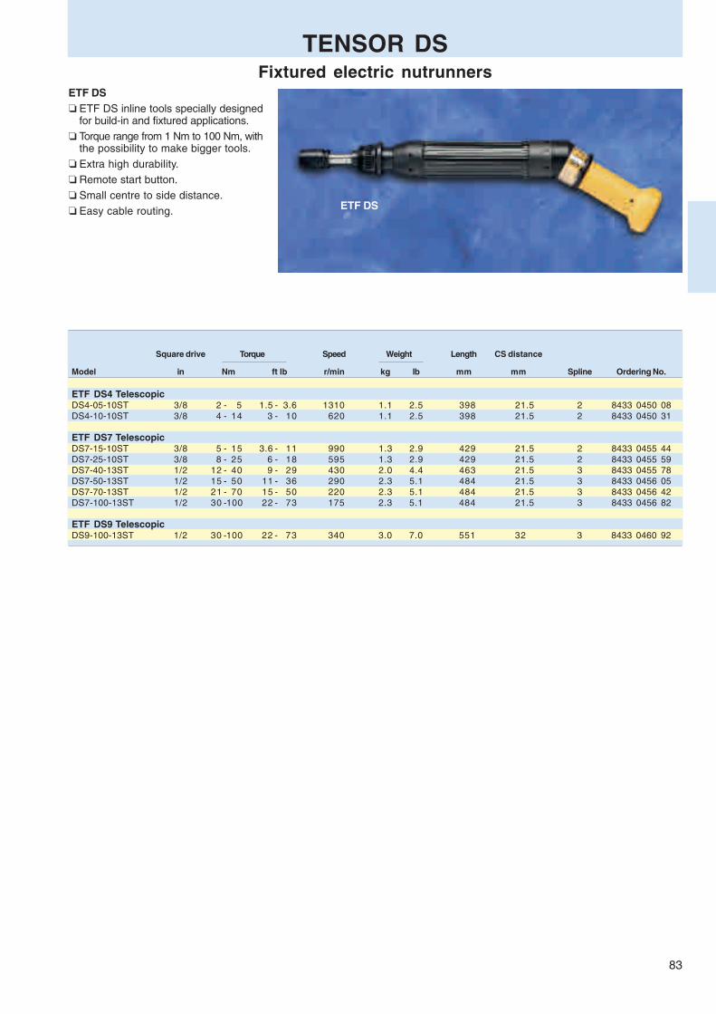
83
ETF DS
Square drive Torque Speed Weight Length CS distance
Model in Nm ft lb r/min kg lb mm mm Spline Ordering No.
ETF DS4 TelescopicDS4-05-10ST 3/8 2 - 5 1.5 - 3.6 1310 1.1 2.5 398 21.5 2 8433 0450 08DS4-10-10ST 3/8 4 - 14 3 - 10 620 1.1 2.5 398 21.5 2 8433 0450 31
ETF DS7 TelescopicDS7-15-10ST 3/8 5 - 15 3.6 - 11 990 1.3 2.9 429 21.5 2 8433 0455 44DS7-25-10ST 3/8 8 - 25 6 - 18 595 1.3 2.9 429 21.5 2 8433 0455 59DS7-40-13ST 1/2 12 - 40 9 - 29 430 2.0 4.4 463 21.5 3 8433 0455 78DS7-50-13ST 1/2 15 - 50 11 - 36 290 2.3 5.1 484 21.5 3 8433 0456 05DS7-70-13ST 1/2 21 - 70 15 - 50 220 2.3 5.1 484 21.5 3 8433 0456 42DS7-100-13ST 1/2 30 -100 22 - 73 175 2.3 5.1 484 21.5 3 8433 0456 82
ETF DS9 TelescopicDS9-100-13ST 1/2 30 -100 22 - 73 340 3.0 7.0 551 32 3 8433 0460 92
ETF DS❏ ETF DS inline tools specially designed
for build-in and fixtured applications.❏ Torque range from 1 Nm to 100 Nm, with
the possibility to make bigger tools.❏ Extra high durability.❏ Remote start button.❏ Small centre to side distance.❏ Easy cable routing.
TENSOR DSFixtured electric nutrunners

84
Torque Speed Weight Length A/F A B C D E F G H R
Model Nm ft lb r/min kg lb mm mm mm mm mm mm mm mm mm mm mm Ordering No.
ETC DS7DS7-25-13-LI3 6 - 28 4.4 - 20.7 622 1.9 4.2 507 13 34 15 13 59 71 94 35 30 13 8433 0710 90
TENSOR DSCrowfoot tools
Torque Speed Weight Length A/F A B C D E F G H R
Model Nm ft lb r/min kg lb mm mm mm mm mm mm mm mm mm mm mm Ordering No.
ETC DS4DS4-05-7-LO3 1 - 5 0.7- 3.7 844 1.5 3.3 400 7 56 9 6 25 32 47 37 15 7.5 8433 0701 04DS4-08-8-LO3 2 - 9.5 1.5- 7 582 1.5 3.3 402 8 60 14 8 26 34 49 37 16 8 8433 0701 08ETC S7DS7-15-10-LO5 3.5- 18 2.6- 13.3 1164 1.7 3.7 474 10 60 15 48 66 76 91 37 22 10 8433 0701 12DS7-20-13-LO3 4.6- 23 3.4- 17 796 1.7 3.7 460 13 58 10 25 47 62 82 44 31 14.5 8433 0701 16DS7-25-13-LO3 5.6- 28 4.2- 20.7 796 1.8 4.0 454 13 62 15 20 42 55 76 44 30 13 8433 0701 23DS7-25-13-LO5 5.6- 28 4.2- 20.7 796 2.0 4.4 514 13 68 15 62 84 97 118 44 30 13 8433 0701 29DS7-40-13-LO3 8.8- 44 6.5- 32.5 478 2.2 4.8 478 13 68 18 25 47 62 82 44 31 14.5 8433 0701 34DS7-40-13-LO5 8.8- 44 6.5- 32.5 478 2.2 4.8 425 13 69 18 72 94 108 129 44 31 14.5 8433 0701 38DS7-60-17-LO3 13 - 65 9.6- 48.1 346 2.7 5.9 507 17 77 24 29 51 66 89 48 30 15 8433 0701 46DS7-60-17-LO5 13 - 65 9.6- 48.1 346 3.3 7.3 558 17 81 24 78 102 117 140 48 30 15 8433 0701 56DS7-80-21-LO3 18 - 90 13.3- 66.6 236 3.3 7.3 585 21 90 20 35 66 86 112 63 40 20 8433 0701 60DS7-80-21-LO5 18 - 90 13.3- 66.6 236 4.1 9.0 651 21 92 20 101 132 152 178 63 40 20 8433 0701 65
ETC DS7 Extra heavy dutyDS7-40-13-AO3 8 - 40 6 - 29 480 2.3 5.0 486 13 60.3 19 33 53 69 86 40 17 16 8433 0702 15DS7-70-17-AO3 14 - 70 11 - 51 345 2.9 6.4 528 17 66.5 19 45 68 87 107 45 21 19.5 8433 0702 32DS7-120-17-AO3 24 - 120 18 - 88 120 4.1 9.0 587 17 88 25 42 68 88 113 51 25 19.8 8433 0702 55
ETC DS9DS9-140-21-LO3 30 - 150 22.2- 111 287 4.8 10.6 638 21 101 33 35 66 86 112 63 40 20 8433 0701 75DS9-200-21-LO3 43 - 215 31.8- 159.1 174 10.0 22.0 718 21 146 40 33 70 91 125 77 42 21 8433 0701 80
For sockets, see separate ordering material (9833 1381 01)
In-Line crowfoot tools
Offset crowfoot tools
For sockets, see separate ordering material (9833 1381 01)
DIMENSIONS
DIMENSIONS

85
Torque Speed Weight Length A/F A B C D E F G H J R
Model Nm ft lb r/min kg lb mm mm mm mm mm mm mm mm mm mm mm mm Ordering No.
ETO DS4DS4-10-10-LI3 2.5- 12 1.9- 8.9 468 1.5 3.4 449 10 32 10 13 37 26 67 34 31 7 11.5 8433 0703 05ETO DS7DS7-15-10-LI3 3 - 15 2.2- 11.1 1046 1.7 3.7 483 10 32 12 11 39 26 68 34 32 8 14 8433 0703 10DS7-18-13-LI3 3.6- 18 2.7- 13.3 743 1.7 3.7 499 13 34 11 15 49 32 84 35 38 8.5 16 8433 0703 15DS7-30-13-LI3 6.6- 33 4.7- 24.3 453 2.4 5.2 525 13 43 18 14 47 31 83 38 40 10.4 25 8433 0703 21DS7-35-13-LI3 7 - 35 5.2- 25.9 438 2.6 5.7 569 13 46 11 21 70 48 113 45 55 12.5 32 8433 0703 25DS7-50-17-LI3 11 - 55 8.2- 40.7 290 3.0 6.6 628 17 46 12 20 81 39 124 45 59 16 32 8433 0703 35DS7-80-19-LI3 16 - 80 11.9- 59.2 226 3.5 7.7 629 19 46 18 17 74 52 137 64 59 17 32 8433 0703 40
For sockets, see separate ordering material (9833 1381 01)
Torque Speed Weight Length A/F A B C D E F G H J R
Model Nm ft lb r/min kg lb mm mm mm mm mm mm mm mm mm mm mm mm Ordering No.
ETO DS4DS4-08-8-LO3 1.7- 8.5 1.3- 6.3 584 1.5 3.3 397 8 59 11 4 22 30 45 37 29 6 10 8433 0703 50ETC DS7DS7-10-10-LO3 2.4- 12 1.8- 8.9 1164 1.6 3.5 434 10 59 10 7 25 35 50 37 31 7 11.5 8433 0703 60DS7-18-13-LO3 3.6- 18 2.7- 13.3 796 1.8 3.9 441 13 61 11 8 30 42 63 44 38 8 15 8433 0703 68DS7-25-13-LO3 5.6- 28 4.2- 20.7 796 1.9 4.2 469 13 65 11 13 37 52 75 48 50 11 31 8433 0703 75DS7-50-17-LO3 11 - 55 8.2- 40.7 346 2.8 6.2 510 17 76 12 18 49 69 97 63 59 16 32 8433 0703 80DS7-80-19-LO3 16 - 80 11.9- 59.2 236 3.7 8.1 568 19 91 18 18 49 63 97 63 59 17 32 8433 0703 85DS7-100-24-LO3 22 - 110 16.3- 81.4 198 4.3 9.5 584 24 92 20 23 60 85 119 74 77 21 33 8433 0703 90
For sockets, see separate ordering material (9833 1381 01)
In-Line tube nut tools
Offset tube nut tools
TENSOR DSTube nut tools
DIMENSIONS
DIMENSIONS

86
ETV S
Square drive Torque Speed Weight Length CS distance
Model in Nm ft lb r/min kg lb mm mm Ordering No.
ETV S4S4-05-10CTADS 3/8 1 - 5 0.7 - 3.6 930 1.5 3.3 382 13.5 8433 0236 26S4-10-10CTADS 3/8 3 - 15 2.2 - 11 650 1.5 3.3 382 13.5 8433 0236 51S4-20-10CTADS 3/8 4 - 20 2.9 -14.4 450 1.5 3.3 382 13.5 8433 0236 91S4-30-10CTADS 3/8 6 - 30 4.4 - 22 270 1.6 3.5 382 13.5 8433 0237 04
ETV S4 Ball RetainerS4-10-B10CTADS 3/8 3 - 15 2.2 - 11 650 1.5 3.3 382 13.5 8433 0236 62
ETV S4 Flush SocketS4-10-FS10 - 3 - 15 2.2 - 11 650 1.4 3.2 382 13.5 8433 0236 69
ETV S4 Female HexS4-10-I06CTADS 1/4 3 - 15 2.2 - 11 650 1.5 3.3 382 13.5 8433 0236 32
ETV S4 Quick ChuckS4-05-QI06 1/4 1 - 5 0.7 - 3.6 930 1.5 3.3 382 13.5 8433 0236 29
ETV S7S7-28-10CTADS 3/8 5 - 29 4 - 21 1300 1.6 3.5 413 13.5 8433 0245 20S7-30-10CTADS 3/8 6 - 35 5 - 25 910 1.6 3.5 413 13.5 8433 0247 33S7-40-10CTADS 3/8 8 - 40 6 - 29 910 1.7 3.7 435 18 8433 0250 00S7-50-10CTADS 3/8 10 - 55 7 - 40 545 1.9 4.2 435 18 8433 0252 87S7-70-13CTADS 1/2 14 - 80 10 - 58 390 2.2 4.8 461 20 8433 0273 09S7-100-13CTADS 1/2 20 - 110 15 - 80 300 2.5 5.5 482 20 8433 0280 00S7-150-13CTADS 1/2 30 - 150 22 - 110 185 2.9 6.4 525 25.5 8433 0288 67S7-200-13CTADS 1/2 40 - 200 29 - 146 160 3.0 6.6 525 25.5 8433 0291 17
ETV S7 Ball RetainerS7-28-B10CTADS 3/8 5 - 29 4 - 21 1300 1.6 3.5 413 13.5 8433 0245 23S7-30-B10CTADS 3/8 6 - 35 5 - 25 910 1.6 3.5 413 13.5 8433 0247 35S7-40-B10CTADS 3/8 8 - 40 6 - 29 910 1.7 3.7 435 18 8433 0250 42S7-50-B10CTADS 3/8 10 - 55 7 - 40 545 1.9 4,2 435 18 8433 0252 62S7-70-B13CTADS 1/2 14 - 80 10 - 58 390 2.2 4.8 461 20 8433 0273 44S7-100-B13CTADS 1/2 20 - 110 15 - 80 300 2.5 5.5 482 20 8433 0280 31S7-150-B13CTADS 1/2 30 - 150 22 - 110 185 2.9 6.4 525 25.5 8433 0288 46S7-200-B13CTADS 1/2 40 - 200 29 - 146 160 3.0 6.6 525 25.5 8433 0291 44
ETV S7 with FanS7-28-10CTADS-F 3/8 5 - 29 4 - 21 1300 1.8 4.0 451 13.5 8433 0245 25S7-30-10CTADS-F 3/8 5 - 35 5 - 25 910 1.8 4.0 451 13.5 8433 0247 92S7-40-10CTADS-F 3/8 8 - 40 6 - 29 910 1.9 4.2 474 18 8433 0250 21S7-50-10CTADS-F 3/8 10 - 55 7 - 40 545 2.1 4.6 474 18 8433 0253 15S7-70-13CTADS-F 1/2 14 - 80 10 - 58 390 2.4 5.3 499 20 8433 0273 68
TENSOR SAngle electric nutrunners
ETV S❏ ETV S right angle tools are ideal for
hand-held operations.❏ Torque range from 1 Nm to 600 Nm.❏ Complete range of Flush Socket and
Hold & Drive tools.❏ Ball retainers for fast and easy socket
changes.❏ Female Hex drive and Quick Chucks
for bits.

87
TENSOR SAngle electric nutrunners
Square drive Torque Speed Weight Length CS distance
Model in Nm ft lb r/min kg lb mm mm Ordering No.
ETV S7 Flush SocketS7-25-CTADS-FS13 - 6 - 25 5 - 18 910 1.6 3.5 413 13.5 8433 0244 12S7-28-FS5/16 - 5 - 29 4 - 21 1300 1.6 3.5 413 13.5 8433 0244 21S7-30-CTADS-FS13 - 6 - 35 5 - 25 910 1.6 3.5 413 13.5 8433 0247 96S7-40-CTADS-FS13 - 8 - 40 6 - 29 910 1.8 4.0 435 18 8433 0251 51S7-50-CTADS-FS13 - 10 - 55 7 - 40 545 1.8 4.0 435 18 8433 0254 14S7-70-CTADS-FS - 14 - 80 10 - 58 390 2.6 5.7 461 20.3 8433 0275 15S7-100-CTADS-FS - 20 - 110 15 - 80 300 3.0 6.7 482 20.3 8433 0282 49S7-150-CTADS-FS - 30 - 150 22 - 110 185 3.3 7.3 525 26 8433 0289 04S7-200-CTADS-FS - 40 - 200 29 - 146 160 3.3 7.3 525 26 8433 0291 79
ETV S7 Hold & DriveS7-28-HAD-SH - 5 - 29 4 - 21 1300 2.1 4.7 436 18.3 8433 0245 74S7-30-HAD-SH - 6 - 35 5 - 25 910 2.1 4.7 436 18.3 8433 0247 90S7-40-HAD-SH - 8 - 40 6 - 29 910 2.1 4.7 436 18.3 8433 0251 64S7-50-HAD-SH - 10 - 55 7 - 40 545 2.1 4.7 436 18.3 8433 0253 74S7-70-CTADS-HAD - 14 - 80 10 - 58 320 3.3 7.3 504 26 8433 0274 15S7-100-CTADS-HAD - 20 - 110 15 - 80 225 3.7 8.2 525 26 8433 0280 97S7-150-CTADS-HAD - 30 - 150 22 - 110 185 3.5 7.7 525 26 8433 0288 93S7-200-CTADS-HAD - 40 - 200 29 - 146 160 3.5 8.4 525 26 8433 0292 27
ETV S9S9-50-13CTADS 1/2 15 - 50 10.8 - 36 1160 4.2 9.2 552 20 8433 0349 47S9-80-13CTADS 1/2 30 - 80 22 - 58 950 4.3 9.4 552 20 8433 0350 03S9-90-13CTADS 1/2 27 - 90 19 - 65 520 4.3 9.4 552 20 8433 0350 14S9-100-13CTADS 1/2 40 - 100 30 - 73 800 4.4 9.7 595 25.5 8433 0350 22S9-180-13CTADS 1/2 45 - 180 33 - 132 450 4.5 9.9 595 25.5 8433 0350 85S9-270-20CTADS 3/4 65 - 270 47 - 198 250 7.4 16.3 661 33.5 8433 0352 39S9-370-20CTADS 3/4 90 - 370 66 - 270 160 7.5 16.5 661 33.5 8433 0352 74S9-450-20CTADS 3/4 135 - 450 97 - 324 150 10.0 22 702 54 8433 0353 15S9-600-25CTADS 1 180 - 600 130 - 432 130 10.1 22.2 702 54 8433 0353 81
ETV S9 Flush SocketS9-80-CTADS-FS - 30 - 80 22 - 58 950 4.7 10.3 552 20.3 8433 0350 09S9-180-CTADS-FS - 45 - 180 33 - 132 450 4.7 10.3 595 26 8433 0350 91S9-270-CTADS-FS - 65 - 270 47 - 198 250 7.4 16.3 661 34.2 8433 0352 45S9-370-CTADS-FS - 90 - 370 66 - 270 160 7.5 16.5 661 34.2 8433 0352 78S9-600-FS - 180 - 600 130 - 432 130 15.6 34.3 701 53 8433 0353 92
ETV S9 Hold & DriveS9-100-CTADS-HAD - 40 - 100 30 - 73 800 4.9 10.8 595 26 8433 0350 28S9-180-CTADS-HAD - 45 - 180 33 - 132 450 5.0 11.0 595 26 8433 0351 01S9-270-HAD - 65 - 270 47 - 198 250 8.2 18 661 34.3 8433 0352 46S9-370-HAD - 90 - 370 66 - 270 160 8.3 18.3 661 34.3 8433 0352 85

88
ETD S
Square drive Torque Speed Weight Length CS distance Spline/
Model in Nm ft lb r/min kg lb mm mm Mounting Ordering No.
ETD S4S4-04-10CTADS 3/8 1 - 5 0.7 - 3.6 1465 1.4 3.1 381 28 – / 1 8433 0237 81S4-10-10CTADS 3/8 3 - 14 2.2 -10.3 690 1.4 3.1 381 28 – / 1 8433 0238 18S4-20-10CTADS 3/8 5 - 20 3.6 - 15 415 1.4 3.1 381 28 – / 1 8433 0239 72
ETD S4 TelescopicS4-04-10CTADST 3/8 1 - 5 0.7 - 3.6 1465 1.5 3.3 419 28 2 / 2 8433 0237 94S4-10-10CTADST 3/8 3 - 14 2.2 -10.3 690 1.5 3.3 419 28 2 / 2 8433 0238 79S4-20-10CTADST 3/8 5 - 20 3.6 - 15 415 1.5 3.3 419 28 2 / 2 8433 0239 84
ETD S4 Female HexS4-02-I06CTADS 1/4 0.5 - 2.5 0.35 - 1.8 2930 1.4 3.1 372 28 – / 1 8433 0237 43S4-04-I06CTADS 1/4 1 - 5 0.7 - 3.6 1465 1.4 3.1 372 28 – / 1 8433 0237 47S4-10-I06CTADS 1/4 3 - 14 2.2 -10.3 690 1.5 3.3 372 28 – / 1 8433 0238 06
ETD S7S7-20-10CTADS 3/8 5 - 20 3.6 - 15 1380 1.6 3.6 411 28 – / 1 8433 0294 42S7-30-10CTADS 3/8 6 - 35 4.4 - 25 830 1.6 3.6 411 28 – / 1 8433 0295 07S7-50-13CTADS 1/2 10 - 55 7.3 - 40 595 2.1 4.7 456 28 2 / 2 8433 0297 37S7-70-13CTADS 1/2 14 - 80 11 - 58 410 2.4 4.7 477 29.5 2 / 2 8433 0298 04S7-90-13CTADS 1/2 20 - 95 15 - 69 335 2.8 6.2 477 29.5 2 / 2 8433 0299 11S7-120-13CTADS 1/2 25 -125 18 - 91 280 2.9 6.5 477 29.5 2 / 2 8433 0299 72
ETD S7 TelescopicS7-20-10CTADST 3/8 5 - 20 3.6 - 15 1380 1.7 3.8 450 28 2 / 2 8433 0294 81S7-20-10CTADS-T50 3/8 5 - 20 3.6 - 15 1380 1.8 4.0 500 28 2 / 2 8433 0294 85S7-30-10CTADST 3/8 6 - 35 4.4 - 25 830 1.7 3.8 450 28 2 / 2 8433 0295 21S7-30-10CTADS-T50 3/8 6 - 35 4.4 - 25 830 1.8 4.0 500 28 2 / 2 8433 0295 84S7-50-13CTADST 1/2 10 - 55 7.3 - 40 595 2.2 4.9 483 28 3 / 5 8433 0297 83S7-50-13CTADS-T50 1/2 10 - 55 7.3 - 40 595 2.3 5.1 540 28 3 / 5 8433 0297 94S7-70-13CTADST 1/2 14 - 80 11 - 58 410 2.5 5.6 504 29.5 3 / 5 8433 0298 34S7-70-13CTADS-T50 1/2 14 - 80 11 - 58 410 2.6 5.7 562 29.5 3 / 5 8433 0298 63S7-90-13CTADST 1/2 20 - 95 15 - 69 335 2.9 6.5 504 29.5 3 / 5 8433 0299 41S7-90-13CTADS-T50 1/2 20 - 95 15 - 69 335 3.0 6.6 562 29.5 3 / 5 8433 0299 43S7-120-13CTADST 1/2 25 -125 18 - 91 280 3.0 6.7 504 29.5 3 / 5 8433 0299 85S7-120-13CTADS-T50 1/2 25 -125 18 - 91 280 3.1 6.8 562 29.5 3 / 5 8433 0299 93S7-140-13CTADST 1/2 35 -140 26 - 103 280 3.0 6.7 504 29.5 3 / 5 8433 0299 98
ETD S❏ ETD S inline tools. The low torque
series is ideal for hand-held benchassembly. The high torque tools areexcellent for fixtured applications.
❏ Torque range from 1 Nm to 2000 Nm.❏ Telescopic spindles for fixtured appli-
cations.❏ Female Hex drives for bits.
TENSOR SStraight electric nutrunners

89
Square drive Torque Speed Weight Length CS distance Spline/
Model in Nm ft lb r/min kg lb mm mm Mounting Ordering No.
ETD S7 Ball RetainerS7-30-B10CTADS 3/8 6 - 35 3.6 - 15 830 1.6 3.6 411 28 – / 1 8433 0295 09S7-50-B13CTADS 1/2 10 - 55 7.3 - 40 595 2.1 4.7 456 28 2 / 2 8433 0297 56S7-70-B13CTADS 1/2 14 - 80 11 - 58 410 2.4 4.7 477 29.5 2 / 2 8433 0298 07
ETD S7 Female HexS7-20-I06CTADS 1/4 5 - 20 3.6 - 15 1380 1.6 3.6 402 28 – / 1 8433 0294 47
ETD S9S9-100-13CTADS 1/2 25 - 100 19 - 73 795 4.0 8.9 547 31.8 2 / 2 8433 0361 52S9-200-13CTADS 1/2 50 - 200 36 - 146 370 4.1 9.1 547 31.8 2 / 2 8433 0362 38S9-270-20CTADS 3/4 65 - 270 47 - 198 250 6.5 14.5 603 36 6 / 8 8433 0363 83S9-450-20CTADS 3/4 110 - 450 80 - 330 140 7.9 17.6 639 40.3 6 / 8 8433 0364 52S9-600-20CTADS 3/4 150 - 600 110 - 440 120 7.9 17.6 639 40.3 6 / 8 8433 0364 82S9-1000-25CTADS 1 250 -1000 180 - 730 76 12.6 27.7 770 46.8 7 / 11 8433 0365 32S9-2000-38CTADS 1 1/2 500 -2000 360 -1460 38 16.8 37 727 67.8 8 / 12 8433 0366 15
ETD S9 TelescopicS9-100-13CTADST 1/2 25 - 100 19 - 73 795 4.1 9.1 574 31.8 3 / 5 8433 0362 08S9-150-13CTADST 1/2 40 - 150 30 - 110 510 4.2 9.4 574 31.8 3 / 5 8433 0362 24S9-200-13CTADST 1/2 50 - 200 36 - 146 370 4.2 9.4 574 31.8 3 / 8 8433 0362 55S9-270-20CTADST 3/4 65 - 270 47 - 198 250 6.7 14.9 653 36 6 / 8 8433 0364 12S9-450-20CTADST 3/4 110 - 450 80 - 330 140 8.0 17.8 689 40.3 6 / 8 8433 0364 61S9-600-20CTADST 3/4 150 - 600 110 - 440 120 8.0 17.8 689 40.3 6 / 8 8433 0364 96S9-1000-25CTADST 1 250 -1000 180 - 730 76 13.0 29.0 824 46.8 7 / 11 8433 0365 14S9-2000-38CTADST 1 1/2 500 -2000 360 -1460 38 18.0 39.6 820 67.8 8 / 12 8433 0366 20
TENSOR SStraight electric nutrunners

90
ETP S
Square drive Torque Speed Weight Length CS distance Spline/
Model in Nm ft lb r/min kg lb mm mm Mounting Ordering No.
ETP S4S4-10-06CTADS 1/4 3 - 12 2.2 - 8.8 735 1.2 2.7 192 21.3 – / – 8433 0235 11S4-10-10CTADS 3/8 3 - 12 2.2 - 8.8 735 1.2 2.7 194 21.3 – / – 8433 0235 39S4-20-10CTADS 3/8 5 - 20 3.6 - 15 415 1.7 3.7 243 21.3 – / – 8433 0235 64ETP S4 Female HexS4-02-I06CTADS 1/4 0.5 - 2.5 0.35 - 1.8 2930 1.2 2.7 200 21.3 – / – 8433 0233 50S42-02-I06 1/4 0.5 - 2.5 0.35 - 1.8 3275 0.9 2.0 188 21.3 – / – 8433 0233 61S4-04-I06CTADS 1/4 1 - 5 0.7 - 3.6 1465 1.2 2.7 200 21.3 – / – 8433 0234 75S42-04-I06 1/4 1 - 5 0.7 - 3.6 1965 0.9 2.0 188 21.3 – / – 8433 0234 84S4-10-I06CTADS 1/4 3 - 12 2.2 - 8.8 735 1.2 2.7 200 21.3 – / – 8433 0235 01S4-10-I06 1/4 3 - 12 2.2 - 8.8 1005 1.0 2.2 188 21.3 – / – 8433 0235 45ETP S4 Ball RetainerS4-10-B10CTADS 3/8 3 - 12 2.2 - 8.8 735 1.2 2.7 194 21.3 – / – 8433 0235 53
ETP S7S7-20-10CTADS 3/8 5 - 20 3.6 - 15 1380 1.9 4.2 274 21.5 – / 1 8433 0313 84S7-30-10CTADS 3/8 6 - 35 4.4 - 25 830 1.9 4.2 274 21.5 – / 1 8433 0314 03S7-50-13CTADS 1/2 10 - 55 7.3 - 40 595 2.2 4.9 318 26.8 2 / 2 8433 0314 91S7-70-13CTADS 1/2 14 - 80 11 - 58 410 2.4 5.4 340 29.5 2 / 2 8433 0315 02S7-90-13CTADS 1/2 20 - 95 15 - 69 533 2.5 5.6 340 29.5 2 / 2 8433 0315 27S7-120-13CTADS 1/2 25 - 125 18 - 91 280 2.7 6.0 340 29.5 2 / 2 8433 0315 43ETP S7 TelescopicS7-30-10CTADST 3/8 6 - 35 4.4 - 25 830 2.0 4.4 313 21.5 2 / 2 8433 0314 15S7-120-13CTADST 1/2 25 - 125 18 - 91 280 2.9 6.4 367 29.5 3 / 5 8433 0315 59ETP S7 Female HexS7-20-I06CTADS 1/4 5 - 20 3.6 - 15 1380 1.9 4.2 265 21.5 – / 1 8433 0313 61S7-30-I06CTADS 1/4 6 - 35 4.4 - 25 830 1.9 4.2 265 21.5 – / 1 8433 0314 28ETP S7 Ball RetainerS7-30-B10CTADS 3/8 6 - 35 4.4 - 25 830 1.9 4.2 274 21.5 – / 1 8433 0314 18
ETP S9S9-70-13CTADS 1/2 25 - 70 18 - 49 1180 3.7 8.3 395 31.8 2 / 2 8433 0367 19S9-100-13CTADS 1/2 40 - 100 29 - 73 795 3.9 8.7 395 31.8 2 / 2 8433 0367 45S9-200-13CTADS 1/2 50 - 200 36 - 146 370 3.9 8.7 395 31.8 2 / 2 8433 0367 86S9-270-20CTADS 3/4 65 - 270 47 - 198 250 6.5 14.5 451 36 6 / 8 8433 0368 52S9-450-20CTADS 3/4 110 - 450 80 - 330 140 7.9 17.6 487 40.5 6 / 8 8433 0368 99S9-600-20CTADS 3/4 150 - 600 110 - 440 120 7.9 17.8 487 40.5 6 / 8 8433 0369 38S9-1000-25CTADS 1 250 -1000 180 - 730 76 12.7 28.3 615 47.5 7 / 11 8433 0370 11S9-2000-38CTADS 1 1/2 500 -2000 360 -1460 38 16.8 37 583 67.8 8 / 12 8433 0371 05ETP S9 TelescopicS9-100-13CTADST 1/2 40 - 100 29 - 73 795 4.0 8.8 422 31.8 3 / 5 8433 0367 51S9-270-20CTADST 3/4 65 - 270 47 - 198 250 6.7 14.8 501 36 6 / 8 8433 0368 63S9-450-20CTADST 3/4 110 - 450 80 - 330 140 8.0 17.6 537 40.3 6 / 8 8433 0369 07S9-600-20CTADST 3/4 150 - 600 110 - 440 120 8.0 17.6 537 40.3 6 / 8 8433 0369 53S9-1000-25CTADST 1 250 -1000 180 - 730 76 13.0 29 669 46.8 7 / 11 8433 0370 31
ETP S❏ ETP S pistol grip tool for both hand-
held and fixtured applications.❏ Torque range from 1Nm to 2000 Nm.❏ Telescopic spindles for fixtured appli-
cations.❏ Female Hex drives for bits.
TENSOR SPistol grip electric nutrunners

91
ETF S
TENSOR SFixtured electric nutrunners
Square drive Torque Speed Weight Length CS distance
Model in Nm ft lb r/min kg lb mm mm Spline Ordering No.
ETF S4S4-10-10CTADS 3/8 3 - 12 2.2 - 8.8 700 1.3 2.9 360 21.5 – 8433 0102 37
ETF S4 TelescopicS4-05-10CTADST 3/8 1.5 - 5 0.7 - 3.6 1460 1.3 2.9 399 21.5 2 8433 0102 23S4-10-10CTADST 3/8 3 - 12 2.2 - 8.8 700 1.3 2.9 399 21.5 2 8433 0102 39
ETF S7 TelescopicS7-15-10CTADST 3/8 4 - 15 2.9 - 11 1090 1.5 3.3 430 21.5 2 8433 0105 48S7-25-10CTADST 3/8 5 - 25 3.6 - 18 680 1.5 3.3 430 21.5 2 8433 0105 67S7-40-13CTADST 1/2 8 - 40 6 - 29 480 2.1 4.7 463 26.8 3 8433 0105 91S7-50-13CTADST 1/2 10 - 55 7.3 - 40 305 2.4 5.4 484 29.5 3 8433 0106 04S7-70-13CTADST 1/2 14 - 80 11 - 58 270 2.8 6.2 484 29.5 3 8433 0106 49S7-100-13CTADST 1/2 20 - 110 15 - 80 225 2.9 6.5 484 29.5 3 8433 0106 70
ETF S9S9-80-13CTADS 1/2 20 - 80 15 - 58 595 4.0 8.9 527 31.8 2 8433 0111 10S9-120-13CTADS 1/2 30 - 120 22 - 88 380 4.1 9.1 527 31.8 2 8433 0111 30S9-180-13CTADS 1/2 45 - 180 33 - 132 275 4.1 9.1 527 31.8 2 8433 0111 50S9-250-20CTADS 3/4 70 - 250 50 - 182 185 6.5 14.5 583 36 6 8433 0111 70S9-400-20CTADS 3/4 100 - 400 73 - 292 105 7.9 17.6 619 40.3 6 8433 0112 00S9-500-20CTADS 3/4 125 - 500 92 - 365 90 7.9 17.6 619 40.3 6 8433 0112 20S9-1000-25CTADS 1 250 -1000 190 - 730 46 13.0 28.6 749 46.8 7 8433 0112 45
ETF S9 TelescopicS9-80-13CTADST 1/2 20 - 80 15 - 58 595 4.1 9.1 554 31.8 3 8433 0111 20S9-120-13CTADST 1/2 30 - 120 22 - 88 380 4.2 9.4 554 31.8 3 8433 0111 40S9-180-13CTADST 1/2 45 - 180 33 - 132 275 4.2 9.4 554 31.8 3 8433 0111 60S9-250-20CTADST 3/4 70 - 250 50 - 182 185 6.7 14.9 633 36 6 8433 0111 80S9-400-20CTADST 3/4 100 - 400 73 - 292 105 8.0 17.8 669 40.3 6 8433 0112 10S9-500-20CTADST 3/4 125 - 500 92 - 365 90 8.0 17.8 669 40.3 6 8433 0112 30S9-800-25CTADST 1 200 - 800 146 - 584 57 13.0 28.6 804 46.8 7 8433 0112 40S9-1500-38CTADST 1 1/2 375 -1500 274 -1095 29 18.0 39.6 800 67.8 8 8433 0112 50
ETF S❏ ETF S inline tools specially designed
for build-in and fixtured applications.❏ Torque range from 1.5 Nm to 1500 Nm.❏ Extra high durability.❏ Remote start button.❏ Small centre to side distance.❏ Telescopic spindles.❏ Easy cable routing.
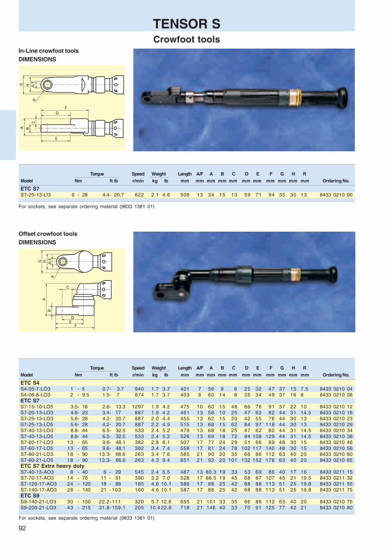
92
Torque Speed Weight Length A/F A B C D E F G H R
Model Nm ft lb r/min kg lb mm mm mm mm mm mm mm mm mm mm mm Ordering No.
ETC S7S7-25-13-LI3 6 - 28 4.4- 20.7 622 2.1 4.6 508 13 34 15 13 59 71 94 35 30 13 8433 0210 90
In-Line crowfoot toolsDIMENSIONS
TENSOR SCrowfoot tools
Offset crowfoot toolsDIMENSIONS
For sockets, see separate ordering material (9833 1381 01)
Torque Speed Weight Length A/F A B C D E F G H R
Model Nm ft lb r/min kg lb mm mm mm mm mm mm mm mm mm mm mm Ordering No.
ETC S4S4-05-7-LO3 1 - 5 0.7- 3.7 940 1.7 3.7 401 7 56 9 6 25 32 47 37 15 7.5 8433 0210 04S4-08-8-LO3 2 - 9.5 1.5- 7 874 1.7 3.7 403 8 60 14 8 26 34 49 37 16 8 8433 0210 08ETC S7S7-15-10-LO5 3.5- 18 2.6- 13.3 1297 1.9 4.2 475 10 60 15 48 66 76 91 37 22 10 8433 0210 12S7-20-13-LO3 4.6- 23 3.4- 17 887 1.9 4.2 461 13 58 10 25 47 62 82 44 31 14.5 8433 0210 16S7-25-13-LO3 5.6- 28 4.2- 20.7 887 2.0 4.4 455 13 62 15 20 42 55 76 44 30 13 8433 0210 23S7-25-13-LO5 5.6- 28 4.2- 20.7 887 2.2 4.9 515 13 68 15 62 84 97 118 44 30 13 8433 0210 29S7-40-13-LO3 8.8- 44 6.5- 32.5 533 2.4 5.2 479 13 68 18 25 47 62 82 44 31 14.5 8433 0210 34S7-40-13-LO5 8.8- 44 6.5- 32.5 533 2.4 5.2 526 13 69 18 72 94 108 129 44 31 14.5 8433 0210 38S7-60-17-LO3 13 - 65 9.6- 48.1 382 2.8 6.1 507 17 77 24 29 51 66 89 48 30 15 8433 0210 46S7-60-17-LO5 13 - 65 9.6- 48.1 382 3.4 7.4 558 17 81 24 78 102 117 140 48 30 15 8433 0210 56S7-80-21-LO3 18 - 90 13.3- 66.6 263 3.4 7.6 585 21 90 20 35 66 86 112 63 40 20 8433 0210 60S7-80-21-LO5 18 - 90 13.3- 66.6 263 4.3 9.4 651 21 92 20 101 132 152 178 63 40 20 8433 0210 65ETC S7 Extra heavy dutyS7-40-13-AO3 8 - 40 6 - 29 545 2.4 5.5 487 13 60.3 19 33 53 69 86 40 17 16 8433 0211 15S7-70-17-AO3 14 - 70 11 - 51 390 3.2 7.0 528 17 66.5 19 45 68 87 107 45 21 19.5 8433 0211 32S7-120-17-AO3 24 - 120 18 - 88 185 4.6 10.1 586 17 88 25 42 68 88 113 51 25 19.8 8433 0211 55S7-140-17-AO3 28 - 140 21 - 103 160 4.6 10.1 587 17 88 25 42 68 88 113 51 25 19.8 8433 0211 75ETC S9S9-140-21-LO3 30 - 150 22.2- 111 320 5.7 12.6 655 21 101 33 35 66 86 112 63 40 20 8433 0210 75S9-200-21-LO3 43 - 215 31.8- 159.1 205 10.4 22.9 718 21 146 40 33 70 91 125 77 42 21 8433 0210 80
For sockets, see separate ordering material (9833 1381 01)

93
In-Line tube nut toolsDIMENSIONS
Offset tube nut toolsDIMENSIONS
TENSOR STube nut tools
Torque Speed Weight Length A/F A B C D E F G H J R
Model Nm ft lb r/min kg lb mm mm mm mm mm mm mm mm mm mm mm mm Ordering No.
ETO S4S4-10-10-LI3 2.5- 12 1.9- 8.9 555 1.7 3.8 450 10 32 10 13 37 26 67 34 31 7 11.5 8433 0212 05ETO S7S7-15-10-LI3 3 - 15 2.2- 11.1 1458 1.9 4.2 484 10 32 12 11 39 26 68 34 32 8 14 8433 0212 10S7-18-13-LI3 3.6- 18 2.7- 13.3 1035 1.9 4.2 500 13 34 11 15 49 32 84 35 38 8.5 16 8433 0212 15S7-30-13-LI3 6.6- 33 4.7- 24.3 630 2.6 5.6 526 13 43 18 14 47 31 83 38 40 10.4 25 8433 0212 21S7-35-13-LI3 7 - 35 5.2- 25.9 610 2.8 6.1 570 13 46 11 21 70 48 113 45 55 12.5 32 8433 0212 25S7-50-17-LI3 11 - 55 8.2- 40.7 405 3.2 6.9 658 17 46 12 20 81 39 124 45 59 16 32 8433 0212 35S7-80-19-LI3 16 - 80 11.9- 59.2 314 3.7 8.1 629 19 46 18 17 74 52 137 64 59 17 32 8433 0212 40
For sockets, see separate ordering material (9833 1381 01)
Torque Speed Weight Length A/F A B C D E F G H J R
Model Nm ft lb r/min kg lb mm mm mm mm mm mm mm mm mm mm mm mm Ordering No.
ETO S4S4-08-8-LO3 1.7- 8.5 1.3- 6.3 648 1.7 3.7 398 8 59 11 4 22 30 45 37 29 6 10 8433 0212 50ETC S7S7-10-10-LO3 2.4- 12 1.8- 8.9 1880 1.8 4.0 435 10 59 10 7 25 35 50 37 31 7 11.5 8433 0212 60S7-18-13-LO3 3.6- 18 2.7- 13.3 1297 2.0 4.4 442 13 61 11 8 30 42 63 44 38 8 15 8433 0212 68S7-25-13-LO3 5.6- 28 4.2- 20.7 533 2.1 4.7 470 13 65 11 13 37 52 75 48 50 11 31 8433 0212 75S7-50-17-LO3 11 - 55 8.2- 40.7 382 3.0 6.7 510 17 76 12 18 49 69 97 63 59 16 32 8433 0212 80S7-80-19-LO3 16 - 80 11.9- 59.2 263 3.9 8.5 568 19 91 18 18 49 63 97 63 59 17 32 8433 0212 85S7-100-24-LO3 22 - 110 16.3- 81.4 179 4.5 10.0 580 24 92 20 23 60 85 119 74 77 21 33 8433 0212 90
For sockets, see separate ordering material (9833 1381 01)

94
DS 300 DriveTensor DS Controller
DS Drive functionality overviewThe drive or controller is the heart of anyelectrical quality-fastening process. Usedboth to control and monitor Tensor DStools, the DS Drive provides a highdegree of functionality with minimal set-up and configuration. There are twoversions: the Basic (D302) model, forstations not requiring multi-torque capa-bility, and the Advanced (D312) model.Simplified installation with DS CompactBoth Basic and Advanced DS Drivesare available as a Compact Hardwareunit. The size and configuration of theCompact Hardware unit makes it easyto install and ideal for multi-controllerinstallations involving more than onespindle. The DS Drive display itselfshows the torque value applied andprovides clear operator feedback, evenat a considerable distance. The unit alsofeatures a built-in six-button keypad forbasic programming.AutoSet – programming made easyProgramming the DS Drive could notbe easier. Hit the Autoset button, set thetarget torque using the +/- keys on thekeypad, press ”Set” – and start fastening!It’s that simple. The DS Drive auto-matically configures the correct speedsand torque shift points for the specificapplication. AutoSet functionality is apatented Atlas Copco design that greatlysimplifies the set-up process and re-duces start-up times.PLC functions banish missing boltsForgotten screws, the most commonassembly problem related to fastening,jeopardize assembly quality and cancreate a potential hazard. In-built PLCfunctions such as ‘batch counting’, and‘line control’ (Advanced) combined withdigital inputs/outputs, alarms and line-interlocking options prevents forgottenscrews and/or parts being passed downthe assembly line or to the next assem-bly station. The Tensor DS ensures thatit is ‘right first time’ – every time.Wireless calibration for zero faultsManual entry of torque values duringthe calibration process is time con-suming and introduces the risk ofhuman error. The DS Drive is linked tothe Atlas Copco ACTA 3000 torquecalibration unit via an infrared port, orvia a cable connected to the RS232serial port. This ‘closed loop’ processsimplifies both torque verification andcalibration processes, while ensuringcomplete process integrity.DigiTorkThe Tensor DS uses DigiTork, the newdigital way of torque control developedby Atlas Copco. Unlike current controlledtools, the microprocessor in the DSDrive takes into consideration the speedand the temperature of the motor aswell as the current and the voltage withwhich you feed the motor.

95
Colour
CompactGraph
POWER FOCUS 3000Tensor DS and S Controller
Market leaderAtlas Copco is the global market leaderfor fastening equipment and secures thisposition with the Power Focus 3000 pro-duct range.
Power Focus 3000 is a modular rangeof controllers with flexibility to be used forapplications ranging from single spindlehand-held operations to fixturised multiplenutrunning systems. Advanced processcontrol and monitoring functions make iteasy to view and collect data using theInternet infrastructure.Total quality controlThe Power Focus 3000 can be com-bined with both Tensor S or DS toolsand is used to control the fastening andassembly process in the station. ThePower Focus 3000 and associated soft-ware packages provide easy to under-stand information for everyone fromoperators to plant managers.All the building blocksThe Power Focus 3000 is based onstandard hardware and software com-ponents which when combined will ful-fill all demands from the most basicnon-networked system to a fully inte-grated unit with the factory network. Themodules fit together using the ‘plug andplay’ concept.Control the assembly processThe Power Focus 3000 incorporatesadvanced control functions to preventthe worker deviating from the requiredprocess. On receipt of assembly infor-mation, the Power Focus automaticallyselects the correct tightening sequenceand parameters. This is a process controlfunction called Job.Built-in connectivityFastening data management and com-munications is a major requirement inmodern assembly operations. Manyplants demand to have instant fasteningdata accessible at different levels in thefactory. Atlas Copco provides standard-ized communication solutions with a solidbase for integration and the flexibility forfuture needs.RBU cuts downtimeAtlas Copco’s patented Rapid BackupUnit (RBU) concept transfers functionalityto an ‘empty’ hardware unit, ensuringthat hardware can easily be upgradedshould functionality requirements change.The RBU also acts as backup for pro-gramming and configuration. If a changeof hardware is required, just fit the RBUto the new hardware, switch on the unitand you’re ready. All programming andnetwork configurations are transferredin seconds. The RBU cuts downtime toa minimum.
Three control units are available for theTensor S tools: Compact, Graph andColour. All have the capability to powerand control every Tensor S spindleproduced.CompactOffers minimum hardware expenditure.Easily stackable to form multiple toolconfigurations.
GraphGives you full stand alone programmingcapability. Functions as a programmingterminal for one or more compact units.ColourProvides full programming functionality,12" TFT colour screen, built-in keyboard.

96
POWER FOCUS 3000Tensor DS and S Controller
FunctionalityThe functionality is unlocked with a keycalled RBU (Rapid Backup Unit). Thispatented device gives you access to thefunctionality you need and providesbackup for your individually program-med data. Four levels of functionalityare available: Gold, Silver, Bronze andDS.
StepSync spindle synchronizationTensor spindles are easily fixtured usingour standard range of TwinSpin com-ponents. StepSync synchronizes Tensorspindles to provide consistent clampforces over the entire component matingface. Synchronization is performed viathe proprietary I/O bus. Depending onuser-interface preferences and budget,the SyncMaster may be a Compact,Graph or Color hardware unit.MultiStage functionality reducesrelaxationThe inherent ‘MultiStage’ functionalitypermits the combination of up to eightdifferent parameter sets in a linear se-quence. The entire process is activatedwith just one press of the tool trigger.For joint conditioning, fasteners can berun down to a pre-torque value, backedoff by a configurable number of degreesand then re-tightened to the desiredfinal torque. This advanced functionalityis ideal for reducing relaxation in a joint.Network the controllers with ‘Cells’The ‘Cell’ concept provides a networkwithout the need for a PC. A ‘Cell’ maycomprise up to 20 units, with a ‘CellMaster’(Compact, Graph or Colour) and theappropriate number of ‘CellMembers’. Ifthe ‘Master’ is a Graph unit, it can function
as a programming and monitoringconsole for the other ‘CellMembers’, viathe high-speed integral Ethernet network.This saves space and cuts hardwarecosts.Advanced statistics for better qualitycontrolStatistical data is collected, analyzedand presented on the Power Focus 3000
DSStand alone functionality:❏ DS tools only❏ 64 PSETs❏ Integrated Ethernet❏ OK/NOK reporting❏ Job functionality❏ MultiStage
functionality❏ Cell functionality❏ Fieldbus option
BronzeStand alone functionality:❏ 64 PSETs❏ Autoset❏ Batch count
SilverAll the functionality of the bronze plus:❏ 250 PSETs❏ Integrated Ethernet❏ Job functionality❏ MultiStage functionality❏ Cell functionality❏ SPC❏ Fieldbus options
GoldAll the functionality of the silver plus:❏ Advanced line control (Cell Job)❏ Synchronisation in a cell
Tensor spindles are easily fixtured using our standard range of TwinSpincomponents. StepSync synchronizes Tensor spindles to provide consistent clampforces over the entire component mating face.
SOFTWARE
screen. Diagnostics and statistical alarmssuch as SPC monitor charts, and capa-bility (Cpk) alarms highlight changes andtrends in the assembly process. Effectiveinformation and SPC are good motiva-tors, and encourage operators to adopt aproactive approach in monitoring thequality of the assembly process.

97
POWER FOCUS 3000Connectivity
Discrete I/O, I/O bus, Fieldbus, Compact, Graph, Colour, PC, access router, hostdatabase.
Communication levelsCell levelThe cell is a key concept in the systemdesign. It is a cluster of max 20 control-lers networked together via built-inEthernet TCP/IP. No need for use of a PC.Factory levelPower Focus 3000 can be integrated withthe factory Ethernet network which en-ables easy access and reporting any-where in the plant.Internet levelWorld wide communication is a matter ofgiving access through a factory networkgateway to Power Focus 3000.Controller levelRealtime communication over I/O busindependent of the factory net.Fieldbus levelThe most common field buses are sup-ported. Profibus, DeviceNet, Interbus,modbus+.

98
POWER FOCUS 3000Configuration and analysis software
ToolsTalk DS – PC-based programmingToolsTalk DS allows complete programming of your DS Drive.There are three programming levels: AutoSet (sets targettorque), QuickProg (sets target torque and joint hardness)and Full Programming. Connect your PC to the drive via theserial RS232 port, open the ToolsTalk DS software applicationand you are talking to the drive. As simple as that. Program-ming structure is intuitive, logical and easy to follow.ToolsTalk PF – remote programmingToolsTalk PF adds the capability to program parameters in allversions of Power Focus 3000 hardware/software configu-
rations, via a user-friendly PC interface. For customizedreporting, ToolsTalk can retrieve all results from a specifiedcontroller. With a simple click, these results can then beimported directly into other commercial software such as MSExcel etc.
ToolsTalk PF communicates with the Power Focus 3000control systems via an RS232 serial connection or anEthernet TCP/IP, either direct or, as is more common in modernplants, via the factory network from the office.

99
POWER FOCUS 3000Software
ToolsNet – Process improvementToolsNet 3000 is a data collection andprocess improvement software appli-cation for use with Power Focus 3000and PowerMACS control systems. Com-bined, these products provide totalcontrol of the assembly process, provi-ding a platform for quality improvements.Historical data, statistics and capabilityindexes can be accessed at any timevia a standard web browser such as MSExplorer. ToolsNet is the complete assem-bly process improvement tool.
Data can be presented historically orin real time. Vehicle and Shift reports areeasy to generate.Traceability minimizes recall costsData can be presented historically or inreal time and Shift reports are easily ge-nerated to satisfy production managers.In the event of warranty recalls, theresult database provides access to cri-tical information which can easily mini-mize the extent of any recall leading to anovernight payback on your investment.
Event Monitor – events in real timeIntegrate the Event Monitor softwareapplication within your plant architectureand monitor Power Focus 3000 eventsremotely, as they occur on the assemblyline, in real time.
Event Monitor can immediately alertyour office PC if the Cpk on a specificcontroller has dropped below a specifiedlevel, or if a tool at a specific workstationrequires preventative maintenance.
Event Monitor is web based. Data canbe accessed from anywhere in the plant,using a standard web browser such asMS Explorer.
Factory Overview – visualizationWhen used with Power Focus 3000 con-trol systems, Factory Overview providesreal time monitoring and visualization ofthe production process. Factory Overviewis a visual aid that presents the momen-tary status of the assembly process for afactory, line or workstation in an easy-to-comprehend form, from anywhere inthe factory.
This object-orientated concept enablestooling, quality and maintenance engi-neers to access all plant data in real time.Factory Overview ensures significant per-formance gains throughout the entire as-sembly process.
Factory Overview also provides a singleportal through which all other Atlas CopcoAssembly Management software applica-tions, such as ToolsTalk PF, ToolsNet andEvent Monitor, can be accessed.

100
General DS 300 Power Focus 3000
Functionality Level / RBU Basic Advanced DS Bronze Silver GoldRuns Tool Types DS DS DS DS / S DS / S DS /S
Tensor controllers
Compact hardware x x x x x xLED display x x x x x x6 button keyboard x x x x x xGraph hardware x xLCD display x xFull keyboard x xColor hardware x x12" TFT colour display x xTouchscreen and PC keyboard x x
FunctionalityNumber of tools 1 1 1 1 1 1Number of Psets 1 10 64 64 250 250Batch count x x x x x xOpen end spanner x x x x x xQuick programming x x x x x xCross thread / Rehit detection x x x x x xTool service indicator x x x x x xAutoset x x x x x xLock on reject x x x x x xLine control x x x xTransducer torque traceability x x xTightening status storage 5 000 5 000 5 000 5 000Tightening data storage 5 000 5 000 5 000MultiStages 8 8 8Trace storage 8 8 8Real time statistics x x xSPC x x xRBU x x x xBar code reading x x xID input to select Pset x x xJob function x x xNumber of jobs 32 99 99ID input to select job x x xComplex job sequencing x x xCell programming x x xLabel printer (via Open protocol) x x xCell Job x
Strategies and optionsTwo stage/Quick step/Ergoramp x x x x x xTorque control and angle monitoring x x x x x xDS control x x x x xAuto zoom step x x x x x xCW / CCW operation x x x x x xRundown angle monitoring x x x x x xSelf tap / PVT monitoring x x x x x xReverse angle x x x x xRotate spindle x x x x xClick wrench input x x xTorque and angle control x x xTorque or angle control x x xAngle control and torque monitoring x x xStep sync x
I/ORS232 programming port x x x x x xDiscrete I/O x x x x x xRemote start x x x x x xSocket selector (optional) x x x x xRE Alarm (optional) x x x x xParallel printer port x x x xI/O Expander (optional) x x x xExpandable I/O (up to 124 in / 124 out) x x x xOperator ID card input x x xFieldbus card Optional Optional OptionalRS232 bar code reader port x x xEasily programmed fieldbus protocol x x xEthernet port for remote prog x x xEthernet port for data collection x x x
TENSORFunctionality overview

101
General DS 300 Power Focus 3000
Functionality Level / RBU Basic Advanced DS Bronze Silver GoldRuns Tool Types DS DS DS DS / S DS / S DS /S
Tensor controllersProtocolsOpen protocol serial x x x xOpen protocol Siemens 3964R serial x x x xOpen protocol Ethernet x x xAPI x x xDouble open protocol sessions x x x
ToolsTalk World 03ToolsTalk FunctionalitySerial connection x x x x x xOff line programming x x x x x xReal time analysis x x x x x xTightening database to PC (Excel) x x x xTightening simulation x x x xOperator monitor x x x xPicture monitor x x x xFieldbus quick set-up x x xJob monitor x x xBar code reader configration x x xEthernet connection x x xRemote programming x x xView tightening traces x x xOverlay traces x x x
Factory Overview World 03Factory Overview FunctionalityVisualisation of controllers on line x x xReal time tightening status x x xToolsTalk link x x xEvent Monitor link x x xToolsNet link x x xPower Focus idle indicator x x xNetwork connection indicator x x xEvent indicator x x xReal time CPK x x x
ToolsNet World 03ToolsNet FunctionalityData collection x x xData evaluation x x xData linked to ID x x xDate range filtering x x xWeb browser interface x x xClient / server solution x x xAuto uploading of missing data x x xAccess / Oracle / SQL compatibility x x xShift reports x x xVehicle reports x x xFull data analysis capablities x x xCustomised reports x x xView tightening traces x xStatistical analysis, histograms, SPC x x
Event Monitor World 03Event Monitor FunctionalityWeb browser interface x x xReal time event monitoring x x xConfigurable event severity x x xEvent grouping functions x x xEvent filtering x x xEvent acknowledgement x x xEvent observation (with comments) x x xEvent history x x x
TENSORFunctionality overview

102
TENSOR MODULARITY
DS Tool / Whip Cable
Tensor DS Tool
Tensor S Tool
The Tensor family uses a modular concept based on standard hardware and software. Combined, it will fulfi ll all assembly industry demands.
ETO
ETC
FS
HAD
ETV
ETP
ETF
ETD
ETO
ETC
FS
HAD
ETV
ETP
ETF
ETD
S/DS Tool / Whip cable
DS Extension Cable
PF3000 Drive
2, 5, 7, 10, 15 m
2, 5, 7, 10, 15 m
5, 10, 15 m
5, 10, 15 m
S/DS Extension Cable
RBU
DS
Bronze
Silver
Gold
Basic DS302
Advanced DS312
Compact
Graph
Color
DS Drive
modularity.indd 102 2003-11-24, 15:01:37Cyanblå (processfärg)Magentaröd (processfärg)Gul (processfärg) Svart (processfärg)

103
TENSORDrives and software
Controller hardwareModel Ordering No.
DS DriveD302-DS4 Basic 8433 0820 48D312-DS4 Advanced 8433 0820 33D302-DS7 Basic 8433 0822 48D312-DS7 Advanced 8433 0822 33D302-DS9 Basic 8433 0824 48D312-DS9 Advanced 8433 0824 33
Power Focus 3000Tensor S/DSPF 3007-G-HW 8433 1700 00PF 3007-C-HW 8433 1700 05PF 3007-COLOUR-HW 8433 1700 07PF 3007-G-DN-HW 8433 1740 00PF 3007-C-DN-HW 8433 1740 05PF 3007-G-PB-HW 8433 1742 00PF 3007-C-PB-HW 8433 1742 05PF 3007-G-IB-HW 8433 1745 00PF 3007-C-IB-HW 8433 1745 05PF 3009-G-HW 8433 1900 00PF 3009-C-HW 8433 1900 05PF 3009-COLOUR-HW 8433 1900 07PF 3009-G-DN-HW 8433 1940 00PF 3009-C-DN-HW 8433 1940 05PF 3009-G-PB-HW 8433 1942 00PF 3009-C-PB-HW 8433 1942 05PF 3009-G-IB-HW 8433 1945 00PF 3009-C-IB-HW 8433 1945 05
Controller software
Software modulesOrdering No.
ToolsNet World 0310 Spindle license 8092 1156 1025 Spindle license 8092 1156 2550 Spindle license 8092 1156 5075 Spindle license 8092 1156 75
125 Spindle license 8092 1156 80200 Spindle license 8092 1156 85350 Spindle license 8092 1156 90500 Spindle license 8092 1156 95
Factory Overview World 0310 Spindle license 8092 1158 1025 Spindle license 8092 1158 2550 Spindle license 8092 1158 5075 Spindle license 8092 1158 75
125 Spindle license 8092 1158 80200 Spindle license 8092 1158 85350 Spindle license 8092 1158 90500 Spindle license 8092 1158 95
Event Monitor World 0310 Spindle license 8092 1157 1025 Spindle license 8092 1157 2550 Spindle license 8092 1157 5075 Spindle license 8092 1157 75
125 Spindle license 8092 1157 80200 Spindle license 8092 1157 85350 Spindle license 8092 1157 90500 Spindle license 8092 1157 95
ToolsTalk PF3000 World 021-user license 8092 1140 015-user license 8092 1140 0510-user license 8092 1140 10Plant license 8092 1140 99
www.pf3000.com – Interactive training2-user license 8092 1200 1010-user license 8092 1200 02
Graph
Compact
Colour
Software Interactive training
Software Ordering No.
RBU-Bronze 8433 0010 10RBU-Silver 8433 0015 20RBU-Gold 8433 0020 20RBU-DS 8433 0005 10
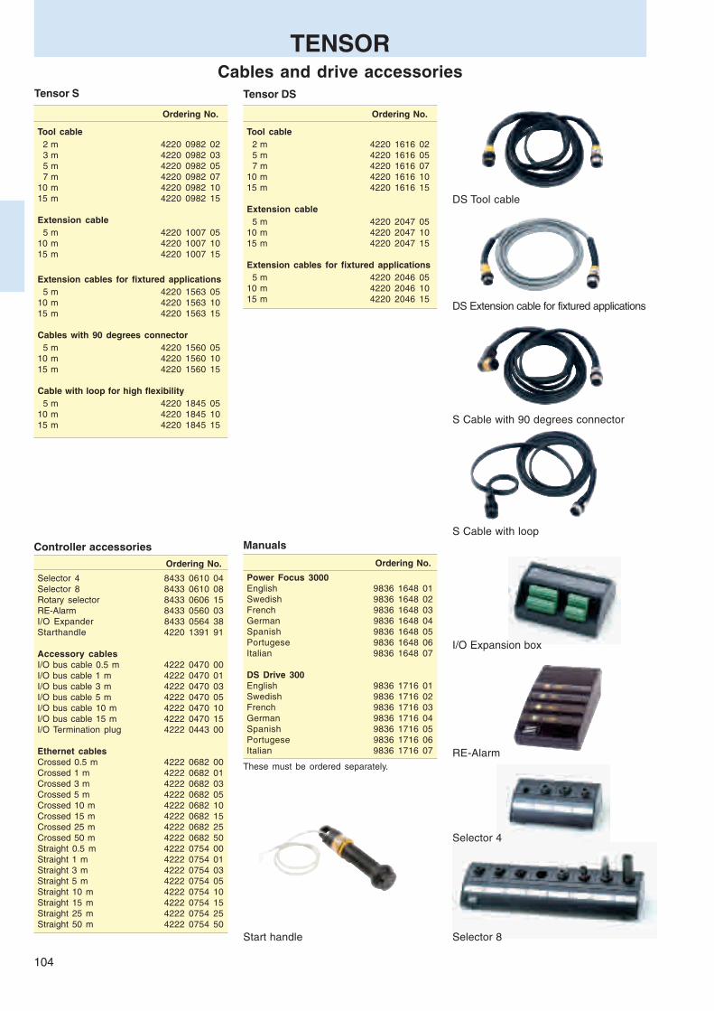
104
Tensor S
Ordering No.
Tool cable 2 m 4220 1616 02 5 m 4220 1616 05 7 m 4220 1616 0710 m 4220 1616 1015 m 4220 1616 15
Extension cable 5 m 4220 2047 0510 m 4220 2047 1015 m 4220 2047 15
Extension cables for fixtured applications 5 m 4220 2046 0510 m 4220 2046 1015 m 4220 2046 15
TENSORCables and drive accessories
Tensor DS
Controller accessories
Ordering No.
Tool cable 2 m 4220 0982 02 3 m 4220 0982 03 5 m 4220 0982 05 7 m 4220 0982 0710 m 4220 0982 1015 m 4220 0982 15
Extension cable 5 m 4220 1007 0510 m 4220 1007 1015 m 4220 1007 15
Extension cables for fixtured applications 5 m 4220 1563 0510 m 4220 1563 1015 m 4220 1563 15
Cables with 90 degrees connector 5 m 4220 1560 0510 m 4220 1560 1015 m 4220 1560 15
Cable with loop for high flexibility 5 m 4220 1845 0510 m 4220 1845 1015 m 4220 1845 15
Ordering No.
Selector 4 8433 0610 04Selector 8 8433 0610 08Rotary selector 8433 0606 15RE-Alarm 8433 0560 03I/O Expander 8433 0564 38Starthandle 4220 1391 91
Accessory cablesI/O bus cable 0.5 m 4222 0470 00I/O bus cable 1 m 4222 0470 01I/O bus cable 3 m 4222 0470 03I/O bus cable 5 m 4222 0470 05I/O bus cable 10 m 4222 0470 10I/O bus cable 15 m 4222 0470 15I/O Termination plug 4222 0443 00
Ethernet cablesCrossed 0.5 m 4222 0682 00Crossed 1 m 4222 0682 01Crossed 3 m 4222 0682 03Crossed 5 m 4222 0682 05Crossed 10 m 4222 0682 10Crossed 15 m 4222 0682 15Crossed 25 m 4222 0682 25Crossed 50 m 4222 0682 50Straight 0.5 m 4222 0754 00Straight 1 m 4222 0754 01Straight 3 m 4222 0754 03Straight 5 m 4222 0754 05Straight 10 m 4222 0754 10Straight 15 m 4222 0754 15Straight 25 m 4222 0754 25Straight 50 m 4222 0754 50
Ordering No.
Power Focus 3000English 9836 1648 01Swedish 9836 1648 02French 9836 1648 03German 9836 1648 04Spanish 9836 1648 05Portugese 9836 1648 06Italian 9836 1648 07
DS Drive 300English 9836 1716 01Swedish 9836 1716 02French 9836 1716 03German 9836 1716 04Spanish 9836 1716 05Portugese 9836 1716 06Italian 9836 1716 07
Selector 4
Selector 8
RE-Alarm
I/O Expansion box
DS Extension cable for fixtured applications
DS Tool cable
S Cable with 90 degrees connector
S Cable with loopManuals
These must be ordered separately.
Start handle

105
TENSORTool accessories
Supported extensions
Model Extension Ordering No.
ETV DS7/S7/ST6/ST8 40-50 142 4220 2209 80180 4220 2202 80
ETV DS7/S7/ST6/ST8 40-50 88 4220 2247 80226 4220 2203 80
Suspension yokes
Tool Model Type Assembly Ordering No.
ETD/ETV/ETF S4 Fixed Motor front nut 4220 1675 86ETD/ETV/ETF S4/S7 Horizontal Motor 4220 0987 80ETD/ETV S4/S7/S9 Vertical Handles 4220 1417 80ETD/ETV/ETF S9 Horizontal Motor 4220 1418 93ETP S4/S7 Horizontal Motor 4220 1154 90
Reaction bars and mounting brackets
Number Spline type Type L / W / H Ordering No.
1 Spline type 0 Bracket 100/60/8 4220 1029 002 Spline type 2 Bracket 70/41/14 4210 2134 023 Triangular 73/72/14 4220 2137 024 Bar 270/35/14 4220 1903 005 Spline type 3 Bracket 100/50/12 4220 2219 036 Triangular 82/80/12 4220 2137 037 Bar 400/29/12 4220 2219 808 Spline type 6 Bracket 200/100/15 4220 1200 009 Triangular 112/109/15 4220 2137 0610 Bar 560/80/15 4220 1200 0111 Spline type 7 Bracket 250/150/20 4220 1445 0012 Spline type 8 Bracket 250/160/20 4220 1972 00
Mounting bracket is included for some tool models.Please match the number from the table with the tool tables.
ExtensionsModel Length Ordering No.
ETD/ETV/ETF DS4/S4 150 4220 1131 80ETD DS7/S7 20-30ETV DS7/S7 30-50ETF DS7/S7 15-40ETD/ETV/ETF DS4/S4 100 4220 1131 80ETD S7 50-120 150 4220 1132 80ETV S7 70-200ETF S7 50-100ETD S9 100ETV S9 50ETF S9 80ETD/ETV DS7 70-200 150 4220 1714 80ETD S9 200 150 4220 1132 81ETD S9 200 100 4220 1132 82ETD/ETV DS9/S9 270-370 150 4220 1585 80ETD DS9/S9 450-600 150 4220 1585 85
Fixtured extensionsFor nut
Model Length Ordering No. Ordering No.
ETV S4/S7 10-50 74 4220 2579 80 4220 0841 01ETV DS4/DS7 10-50 4220 1640 01ETV S7/S9 70-200 73 4220 2469 80 4220 0848 01ETV DS7/DS9 70-200 4220 1663 01ETV S9/DS9 270-600 91 4220 2614 80 Included
Lever
Model Ordering No.
Lever 4220 1642 80Extended lever 4220 1642 85Safety lever 4220 2356 80
Safety lever Lever
Extended lever
Fixtured extension Extension
Mounting bracket Triangular
Reaction bar
Suspension yokes
Supported extensions

106
TENSORTool accessories
Protective coverModel Ordering No
ETV DS4/S4, DS7/S7 28-30 9040 0900 08ETV S7 40-50 9040 0900 09ETV S7 70-100 9040 0900 10ETV S9 50 9040 0900 11ETV DS7 40-50 9040 0900 33ETV DS7 70-100 9040 0900 34ETP S4/DS4 10 9040 0900 12
Telescopic front parts for ETV
Model Holder Front part Nut
DS7/S7 40/50 4220 1673 80 4220 1145 90 4220 0841 01DS7/S7 70/100 4220 1811 81 4220 1135 95 4220 0841 01DS7/S7 150/200 4220 1592 81 4220 1135 93 4220 0848 01DS9/S9 4220 1960 80 4220 1179 91 Included
Torque multiplierMax
Torque Gear Square SquareModel Nm ratio in out Ordering No.
T-Mult 120 30 4.54 3/8 1/2 8431 0453 53T-Mult 200 50 4.62 3/8 3/4 8433 0310 07T-Mult 400 100 4.10 1/2 3/4 8431 0493 65T-Mult 500 30 16.11 3/8 3/4 8433 0310 28T-Mult 800 45 18.50 1/2 1 8433 0311 81T-Mult 1000 250 4.00 3/4 1 8433 0312 16T-Mult 1500 72 21.10 1/2 1 8433 0312 20
Mounting bracket and nut (included with T-mult)Model Mounting bracket Nut
T-Mult 120 4210 2134 00 4210 2135 00T-Mult 200 4210 2219 03 4210 2218 00T-Mult 400 4210 2183 00 4210 2182 00T-Mult 500 4210 2183 00 4210 2182 00T-Mult 800 4210 2726 00 4210 2725 00T-Mult 1000 4210 2726 00 4210 2725 00T-Mult 1500 4210 3899 80 4210 3936 00
Protective cover
Telescopic front part
Torque multiplier

107
PowerMACS
PowerMACS/QMXWhere requirements for functionality,durability and flexibility are the highest,PowerMACS and the QMX nutrunnersprovide the solution for you.
PowerMACS is the controller/servocontrolling the QMX nutrunners. Theseproducts are typically used for fixturedinstallations – automated, semi-automatedor manually operated.
The PowerMACS controller can bebuilt into a cabinet or used as a StandAlone. The Stand Alone concept is aunique way of installing these advancedsystems in a very simple manner, trueplug & play. Advanced products do nothave to mean complex handling anymore.
The QMX nutrunners are extremelyrobust and durable, standing up to thetoughest environments. At the sametime they are small and fast, allowingergonomically built multiples. Don’t letyour ergonomics requirements slip justbecause you are using a multiple.
❏ Nutrunner sequencing – This allowsnutrunners to be sequenced at eachphase of the tightening process allow-ing even distribution of torque to eachfastener.
❏ Even torque distribution – Wherethere is uneven torque distribution,part damage or distortion could occurwith possible fastener failure or lossof residual torque.
❏ Snug, threshold, final torque in onepass – No need for multiple torquestage sequencing as with a singlenutrunner tool. Fixtured nutrunnerssave time and effort from start to fi-nish.
❏ No missed fasteners – With multiplenutrunners there is a spindle dedi-cated to each location, ensuring qualityon every rundown on every bolt.
❏ Better residual torques – Synchro-nized controlled fastening allowsresidual torque levels to be moreconsistent with the dynamic torquespecification.
❏ Saving in cycle time – Comparedwith using a single nutrunner toolwith many rundowns, running all fas-teners simultaneously reduces in-sta-tion cycle time.
❏ Cost saving benefits – Saving in-station cycle time frees up operatorsto handle additional tasks and poten-tially reduce labor requirements, atthe same time eliminating bottlenecks.

108
TC52P/54P TC52S/54S
PowerMACSAlready ex-stock as a standard com-ponent, PowerMACS is ready to take onthe most demanding jobs. You do nothave to add external devices to get going.Power it up, program it and you are readyto go.
It is also built to communicate. Connectthe PowerMACS system to your networkvia the built-in Ethernet port or connectit to your fieldbus network (option) to com-municate production data.
There is even a PLC on board, allow-ing you to program any logic sequenceyou like. The PLC is standard, includedwhen you order a PowerMACS.
Production up-time is ensured by flashPROM memory and RAM back-up me-mory. We know the value for you ofkeeping production going and did notcompromise on reliability when we de-signed this system.
❏ Plenty of memory for handling cycledata, statistics, SPC, cycle traces, sta-tion events, etc.
❏ Peripheral support for barcodereaders, printers and special commu-nication protocols.
❏ API- Server (Application ProgramInterface) software component usingTCP/IP.
PowerMACS
Model Type Ordering No.
Stand Alone TCs 570V/20A (IP54) for QMX42 – QMX62TC52 S-N Stand Alone – No FieldBus 4240 0440 81TC52 S-P Stand Alone – ProfiBus 4240 0441 81TC52 S-I Stand Alone – InterBus 4240 0442 81TC52 S-D Stand Alone – DeviceNet 4240 0443 81TC52 S-M Stand Alone – ModBus Plus 4240 0444 81Stand Alone TCs 570V/40A (IP54) for QMX80 – QMX90TC54 S-N Stand Alone – No FieldBus 4240 0450 81TC54 S-P Stand Alone – ProfiBus 4240 0451 81TC54 S-I Stand Alone – InterBus 4240 0452 81TC54 S-D Stand Alone – DeviceNet 4240 0453 81TC54 S-M Stand Alone – ModBus Plus 4240 0454 81Panel TCs (IP20) 570V/20A for QMX42 – QMX62TC52 P-N Panel – No FieldBus 4240 0410 81TC52 P-P Panel – ProfiBus 4240 0411 81TC52 P-I Panel – InterBus 4240 0412 81TC52 P-D Panel – DeviceNet 4240 0413 81TC52 P-M Panel – ModBus Plus 4240 0414 81Panel TCs (IP20) 570V/40A for QMX80 – QMX90TC54 P-N Panel – No FieldBus 4240 0430 81TC54 P-P Panel – ProfiBus 4240 0431 81TC54 P-I Panel – InterBus 4240 0432 81TC54 P-D Panel – DeviceNet 4240 0433 81TC54 P-M Panel – ModBus Plus 4240 0434 81
PowerMACS – Tightening controllers
❏ Fieldbus flexibility to handle data andI/O communications.
❏ On board operating system with realtime configurable PLC to handle allin-station functions.
❏ True nutrunner synchronizationachieved using high speed internalEthernet communications.
❏ Installation flexibility with externaland panel mounted controllers.
❏ Inertia braking capabilities to absorbthe inertia during a high speed run-down on a hard joint, allowing for pro-ductivity and accuracy at the sametime.

109
QMX62-19RT
QMX90-95ROT
PowerMACSQMX nutrunners and cables
QMX nutrunnersQMX is designed to last in the toughestenvironments. With its high speed andoutstanding durability it will meet yourmost stringent demands.
The electric motor in the QMXnutrunners is a proprietary Atlas Copcobrushless DC motor. It is highly efficient,allowing for it to put out high power at ahigh cycle rate without overheating. Thedesign uses resolver technology. All ofthis together allows QMX to be certifiedto the highest levels of both accuracyand durability.
Our range includes standard tools inseveral different configurations of whicha sample appears in the catalogue.Should you require more information,please contact your local Atlas Copcorepresentative.❏ Resolver technology enables us to
run unique tightening strategies andgauging applications.
❏ Increased productivity due to fasternutrunner speeds resulting from ahigher bus voltage.
❏ Torque range from 6-4000 Nm.❏ MTBF better than 5 million cycles, un-
der normal conditions.❏ Adjustable single cable connector de-
sign for cable management flexibility.❏ ISO certified to +/- 2.5% accuracy and
1 million duty cycles on hard and softjoints.
❏ Excellent nutrunner C-C distanceswhen comparing power-to-weightratio.
❏ Low moment of rotor inertia, desig-ned for high dynamic applications.
❏ Co-axial nutrunner design to handledual nutrunner functionality on spe-cial applications.
QMX cablesCable integrity is the most crucial com-ponent of any system. QMX cables aredesigned with a robust extruded con-nector and a super-flex jacket for in-creased durability.❏ Reduced spare parts due to a single
cable design.❏ 3-in-1 Power, Resolver, and Transducer
connections built into one cable de-sign.
❏ Super-flex cables provide increasedlife.
❏ Cable lengths in combinations up to35 meters.
QRTTTranducers used for both QMX nut-runners and fixtured Tensor tool calibra-tion. This transducer enables fast andeasy set-up with highest system accu-racy. By using the QRTT, no special testadapter between the nutrunner and theproduct itself is now needed (for furtherinformation see page 131).

110
D
BA C
A E
D
BA C
Base plate position
Alternative position for base plate
Alternative position for base plate
Socketholder Socket
Travel Torque range Max Min Weight Gear size holdera A B C D E
Type in Nm ft lb speed C-C kg lb ratio in Ordering No. Ordering No. mm mm mm mm mm
QMX42-2RT 2 6 - 20 4 - 14 1200 42 3.2 1.5 7.5 3/8 8432 5120 10 4230 1818 00 134 23 386 15 -QMX42-2ROT 2 6 - 18 4 - 13 1200 31 4.3 2.0 7.5 3/8 8432 5120 20 4230 1818 00 134,5 - - - 436QMX42-5RT 2 10 - 50 7 - 35 560 42 3.5 1.6 21.3 1/2 8432 5130 10 4230 1819 00 134 23 412 15 -QMX42-5ROT 2 10 - 50 7 - 35 560 31 4.6 2.1 21.3 1/2 8432 5130 20 4230 1819 00 134,5 - - - 463QMX50-9RT 2 20 - 90 15 - 65 560 50 5.9 2.7 18.2 1/2 8432 5140 10 4230 1820 00 137 23 462 15 -QMX50-9ROT 2 20 - 85 15 - 60 560 37 8.1 3.7 18.2 1/2 8432 5140 20 4230 1820 00 137 - - - 519QMX50-15RT 2 30 - 150 22 - 110 330 50 5.8 2.6 31.3 1/2 8432 5150 10 4230 1820 00 137 23 462 15 -QMX50-15ROT 2 30 - 145 22 - 105 330 37 8.0 3.6 31.3 1/2 8432 5150 20 4230 1820 00 137 - - - 519QMX62-19RT 2 40 - 190 30 - 140 330 62 9.5 4.3 19.4 5/8 8432 5160 10 4230 1821 00 152 25 525,5 15 -QMX62-19ROT 2 40 - 180 30 - 130 330 45 12.9 5.9 19.4 5/8 8432 5160 20 4230 1821 00 152,5 - - - 569,5QMX62-32RT 2 70 - 320 50 - 235 200 62 10.2 4.6 32.1 3/4 8432 5170 10 4230 1822 00 152,5 - - - 571QMX62-32ROT 2 70 - 290 50 - 210 200 45 13.5 6.1 32.1 3/4 8432 5170 20 4230 1822 00 152,5 - - - 571QMX80-58RT 2 120 - 580 90 - 425 200 80 20.0 9.1 29.6 3/4 8432 5180 10 4230 1971 00 146 30 610 20 -QMX80-58ROT 2 120 - 550 90 - 405 200 55 21.0 9.5 29.6 3/4 8432 5180 20 4230 1971 00 146 - - - 671,5QMX90-95RT 2 200 - 950 150 - 700 130 91 22.0 10.0 46.8 1 8432 5190 10 4230 1824 00 152 32 621 20 -QMX90-95ROT 2 200 - 900 150 - 660 130 63 30.0 13.6 46.8 1 8432 5190 20 4230 1824 00 152,5 - - - 698,5
Standard nutrunnerAtlas Copco standard DC electricbrushless resolver nutrunners. Thesestate-of-the-art nutrunners are used in awide variety of fastening applicationsranging from automotive to generalindustrial.
Socketholder Socket
Travel Torque range Max Min Weight Gear size holdera A B C D E
Type in Nm ft lb speed C-C kg lb ratio in Ordering No. Ordering No. mm mm mm mm mm
QMX42-2RT 3 6 - 20 4 - 14 1200 42 3.2 1.5 7.5 3/8 9831 4045 08 4231 0544 00 190 23 386 15 -QMX42-5RT 3 10 - 50 7 - 35 560 42 3.7 1.7 21.3 1/2 9831 4045 10 4231 0544 01 190 23 412 15 -QMX50-9RT 3 20 - 90 15 - 65 560 50 6.5 2.9 18.2 1/2 9831 4046 04 4231 0491 00 200 23 464 15 -QMX50-15RT 3 30 - 150 22 - 110 330 50 7.0 3.2 31.3 1/2 9831 4046 06 4231 0491 00 201 25 462 15 -QMX62-19RT 3 40 - 190 30 - 140 330 62 9.8 4.4 19.4 1/2 9831 4047 12 4231 0513 00 200 25 526 15 -QMX62-32RT 3 70 - 320 50 - 235 200 62 10.5 4.8 32.1 3/4 9831 4047 14 4231 0484 00 200 25 527 15 -QMX80-58RT 3 120 - 580 90 - 425 200 80 21.0 9.5 29.6 3/4 9831 4048 04 4231 2664 00 214 43 623 20 -QMX90-95RT 3 200 - 950 150 - 700 130 91 23.0 10.4 46.8 1 9831 4058 18 4231 1106 00 176 32 670 20 -QMX42-5RT 4 10 - 50 7 - 35 560 42 8 3.6 21.3 3/8 9831 4045 53 4231 2055 00 191 23 510 15 -QMX50-15RT 4 30 - 150 22 - 110 560 50 11 5.0 31.3 1/2 9831 4067 15 4231 3189 00 186 23 565 15 -
Special nutrunnersExtended spring travel 3" and 4".Atlas Copco special DC electric brush-less resolver nutrunner with extendedspring travel for longer bolt lengths.
PowerMACS
a The socket holder is included in the product.
a The socket holder is included in the product.

111
A
D
D
BA C
Alternative position for base plate
Most common position for base plate
Dual transducers, RTT.Atlas Copco special DC electric brush-less resolver nutrunners with dual torquetransducer feedback. This allows fortransducer redundancy, with the abilityto verify that readings are within acertain tolerance of one another.Dual transducers and angle feedback,RATT.Atlas Copco special DC electric brush-less resolver nutrunners with dualangle and torque transducer feedback.This allows for angle and torqueverification, with the ability to doublecheck whether the system is readingaccurately.
Socketholder Socket
Travel Torque range Max Min Weight Gear size holdera A B C D E
Type in Nm ft lb speed C-C kg lb ratio in Ordering No. Ordering No. mm mm mm mm mm
QMX42-7RTV - 15 - 70 11 - 50 360 (40) 3.7 1.7 36.1 1/2 9831 4045 46 -QMX42-7RTV 2 15 - 70 11 - 50 360 (38) 5.3 2.4 36.1 1/2 9831 4045 32 4231 2797 00 - - - - -QMX42-7RTV 1 15 - 70 11 - 50 360 (38) 5.1 2.3 36.1 1/2 9831 4045 64 4231 3207 00 - - - - -QMX42-2RTV - 6 - 30 4 - 22 1000 (36) 3.5 1.6 11.7 3/8 9831 4045 95 - - - - - -QMX50-14RTV - 30 - 140 22 - 100 320 (51) 6.2 2.8 33.9 1/2 9831 4046 84 - 141 - - 15 476QMX50-20RTV - 40 - 160 30 - 115 190 (51) 6.1 2.8 58 1/2 9831 4046 78 - 141 - - 15 476QMX62-34RTV - 70 - 340 50 - 250 190 67 13.5 6.1 36.0 3/4 9831 4047 46 - 153 - - 14 548,5QMX62-34RTV 1 70 - 340 50 - 250 190 62 14.5 6.6 36.0 3/4 9831 4047 31 4231 2416 00 - - - - -QMX62-60RTV - 120 - 600 90 - 440 60 106 21 9.5 105 3/4 9831 4047 21 - - - - - -QMX62-60RATTV 2 120 - 600 90 - 440 60 106 23 10.4 105 3/4 9831 4047 50 4231 3018 00 - - - - -
PowerMACS
Socketholder Socket
Travel Torque range Max Min Weight Gear size holdera A B C D E
Type in Nm ft lb speed C-C kg lb ratio in Ordering No. Ordering No. mm mm mm mm mm
RTTQMX42-2RTT 2 6 - 20 4 - 14 1200 42 3.2 1.45 7.5 3/8 9831 4045 99 4230 1818 00 134 23 386 15 -QMX42-5RTT 2 10 - 50 7 - 35 560 42 3.5 1.5 21.3 1/2 9831 4068 00 4230 1819 00 134 23 412 15 -QMX50-9RTT 2 20 - 90 15 - 65 560 50 5.9 2.7 18.2 1/2 9831 4067 09 4230 1820 00 137 23 462 15 -QMX50-15RTT 2 30 - 150 22 - 110 330 50 5.9 2.7 31.3 1/2 9831 4067 05 4230 1820 00 137 23 462 15 -QMX62-19RTT 2 40 - 190 30 - 140 330 62 9.5 4.3 19.4 5/8 9831 4047 84 4230 1821 00 152 25 526 15 -QMX62-32RTT 2 70 - 320 50 - 235 200 62 10.2 4.6 32.1 3/4 9831 4047 61 4230 1822 00 152 25 527 15 -QMX80-58RTT 2 120 - 580 90 - 425 200 80 20 9.1 29.6 3/4 9831 4048 17 4230 1971 00 146 30 610 20 -QMX90-95RTT 2 200 - 950 150 - 700 130 91 22 10.0 46.8 1 9831 4058 34 4230 1824 00 152 32 621 20 -RATTQMX42-2RATT 2 6 - 20 4 - 14 1200 42 3.7 1.7 7.5 3/8 8432 5120 70 4230 1818 00 134 23 386 15 -QMX42-5RATT 2 10 - 50 7 - 35 560 42 3.9 1.8 21.3 1/2 8432 5130 70 4230 1819 00 134 23 412 15 -QMX50-9RATT 2 20 - 90 15 - 65 560 50 6.0 2.7 18.2 1/2 8432 5140 70 4230 1820 00 137 23 462 15 -QMX50-15RATT 2 30 - 150 22 - 110 330 50 6.0 2.7 31.3 1/2 8432 5150 70 4230 1820 00 137 23 462 15 -QMX62-19RATT 2 40 - 190 30 - 140 330 62 10.0 4.5 19.4 5/8 8432 5160 70 4230 1821 00 152 25 526 15 -QMX62-32RATT 2 70 - 320 50 - 235 200 62 10.8 4.9 32.1 3/4 8432 5170 70 4230 1822 00 152 25 527 15 -QMX80-58RATT 2 120 - 580 90 - 425 200 80 21.0 9.5 29.6 3/4 9831 4048 18 4230 1971 00 146 30 610 20 -QMX90-95RATT 2 200 - 950 150 - 700 130 91 22.5 10.2 46.8 1 9831 4058 35 4230 1824 00 152 32 621 20 -
Angle head toolsAtlas Copco special DC electric brush-less resolver nutrunners with a rightangle head. This simplifies hard-to-reach applications with the ability toposition the nutrunners in anyorientation.
a The socket holder is included in the product.
a The socket holder is included in the product.

112
Socketholder Socket
Travel Torque range Max Min Weight Gear size holdera
Type in Nm ft lb speed C-C kg lb ratio in Ordering No. Ordering No.
QMX42-5RVT 3 10 - 50 7 - 35 560 42 5 2.3 21.3 3/4 9831 4045 56 4231 2473 00QMX50-15RVT 2 30 - 145 22 - 105 300 55 9.4 4.3 31.3 1/2 9831 4046 85 4230 1819 00QMX62-28RVT 2 50 - 280 35 - 205 190 82 16.4 7.4 32.1 3/4 9831 4047 36 4230 1822 00QMX90-95RVT 2 200 - 950 150 - 700 130 108 30 13.6 46.8 3/4 9831 4058 17 4230 1824 00
Angle nutrunnerAtlas Copco special DC electric brushless resolver nutrunners with a right angle head and spring travel. The right angleallows these tools to be positioned in hard-to-reach locations without putting strain on it.
U-nutrunnerAtlas Copco special DC electric brushless resolver nutrunners with ”U” design. This design allows our tools to be positionedin locations with minimal nutrunner length clearances - for instance exhaust manifold or indexing applications.
Socketholder Socket
Travel Torque range Max Min Weight Gear size holdera
Type in Nm ft lb speed C-C kg lb ratio in Ordering No. Ordering No.
QMX42-5RUT 2 20 - 50 15 - 35 560 42 5.5 2.5 21.3 1/2 9831 4045 45 4230 1819 00QMX50-9RUT 3 15 - 80 110 - 55 560 50 8 3.6 18.2 1/2 9831 4046 31 4230 1820 00QMX50-15RUT 3 30 - 140 22 - 100 330 50 8 3.6 31.3 1/2 9831 4046 26 4230 1820 00QMX62-19RUT 2 30 - 170 22 - 125 330 88 15 33 19.4 3/4 9831 4047 37 4230 1822 00QMX62-32RUT 2 55 - 280 40 - 205 200 88 18 8.2 32.1 3/4 9831 4047 35 4230 1822 00QMX95-200RUT 1/2 350 -1750 260 -1250 60 95 34 15.4 98 HEX 9831 4058 32 not available
Co-axial nutrunnerAtlas Copco special DC electric brushless resolver nutrunners with co-axial design. This design allows our tools to performspecial gauging or fastening applications. Essentially it is a nutrunner inside a nutrunner. This gives us the ability to use thecentre nutrunner to set a position or torque while the outside nutrunner synchronizes and locks the position with a lock nut ormonitors for excessive friction.
Socketholdera
Travel Torque range Max Min Weight Gear size
Type in Nm ft lb speed C-C kg lb ratio in Ordering No.
QMX42-2RT/QMX42-5ROT 1 / 1 15 / 63 110 / 45 270 / 170 44 10 22 16.00 / 41.23 1/4 / 3/4 9831 4045 62QMX42-2RT/QMX42-5ROT 1 / 1 20 / 50 15 / 35 1200 / 560 44 10 22 7.5 / 21.33 1/4 / 3/4 9831 4045 83QMX42-5RT/QMX50-15RT 1 / 1 50 / 50 35 / 110 200 / 350 64 15 33 21.33 / 31.24 3/8 / 3/4 9831 4046 35QMX80-55RT/QMX80-10RT 11/2 / – 550 / 100 400 / 75 200 / 100 216 48 105 29.56 / 48.44 3/4 / – 9831 4 040 65
PowerMACS
a The socket holder is included in the product.
a The socket holder is included in the product.
Cables Stand Alone
a The socket holder is included in the product.
Type Ordering No.
Cable between spindle and TC, 5 m 4231 5062 05*Cable between spindle and TC, 10 m 4231 5062 10*Cable between spindle and TC, 15 m 4231 5062 15*Cable between spindle and TC, 20 m 4231 5062 20*Cable between spindle and TC, xxa m 4231 5062 xx**Cable between PBU and TC, 1 m 4231 5063 01*Cable between PBU and TC, 2 m 4231 5063 02*Cable between PBU and TC, 3 m 4231 5063 03*Cable between PBU and TC, xxa m 4231 5063 xx**
a Available from 1 meter to 35 meters. Replace the two last digits in the ordering number for length of cable.
* Available directly from stock.** Manufactured to order.

113
PowerMACS
Additionalsocket Socket Socketholder holder holdera
mm Product No. size Ordering No.
0b 8432 5120 10 3/8" 4230 1818 0050 9831 4063 08 3/8" 4231 0065 30
100 9831 4063 10 3/8" 4231 0065 31150 9831 4063 12 3/8" 4231 0065 32200 9831 4063 14 3/8" 4231 0065 33250 9831 4063 16 3/8" 4231 0065 34
0 9831 4063 07 1/2" 4230 1819 0050 9831 4063 09 1/2" 4231 0065 35
100 9831 4063 11 1/2" 4231 0065 36150 9831 4063 12 1/2" 4231 0065 37200 9831 4063 14 1/2" 4231 0065 40250 9831 4063 69 1/2" 4231 0065 39
QMX62-19RT
Additionalsocket Socket Socketholder holder holdera
mm Product No. size Ordering No.
0 9831 4063 17 3/8" 4230 1818 0050 9831 4063 18 3/8" 4231 0065 30
100 9831 4063 20 3/8" 4231 0065 31150 9831 4063 22 3/8" 4231 0065 32200 9831 4063 24 3/8" 4231 0065 33250 9831 4063 26 3/8" 4231 0065 34
0b 8432 5130 10 1/2" 4230 1819 0050 9831 4063 19 1/2" 4231 0065 35
100 9831 4063 21 1/2" 4231 0065 36150 9831 4063 23 1/2" 4231 0065 37200 9831 4063 25 1/2" 4231 0065 40250 9831 4063 27 1/2" 4231 0065 39
Additionalsocket Socket Socketholder holder holdera
mm Product No. size Ordering No.
0b 8432 5140 10 1/2" 4230 1820 0050 9831 4063 28 1/2" 4231 0070 25
100 9831 4063 29 1/2" 4231 0070 21150 9831 4063 30 1/2" 4231 0070 22200 9831 4063 31 1/2" 4231 0070 23250 9831 4063 32 1/2" 4231 0070 24
Additionalsocket Socket Socketholder holder holdera
mm Product No. size Ordering No.
0b 8432 5150 10 1/2" 4230 1820 0050 9831 4063 68 1/2" 4231 0070 25
100 9831 4063 33 1/2" 4231 0070 21150 9831 4063 34 1/2" 4231 0070 22200 9831 4063 35 1/2" 4231 0070 23250 9831 4063 36 1/2" 4231 0070 24
QMX62-32RT
Atlas Copco special socket holder designs allow you to reachinto applications or parts with tight clearances.
QMX42-2RT
QMX42-5RT
QMX50-9RT
QMX50-15RT
Additionalsocket Socket Socketholder holder holdera
mm Product No. size Ordering No.
0 9831 4063 70 1/2" 4230 1829 0050 9831 4063 37 1/2" 4231 0075 11
100 9831 4063 40 1/2" 4231 0075 12150 9831 4063 43 1/2" 4231 0075 13200 9831 4063 46 1/2" 4231 0075 14250 9831 4063 49 1/2" 4231 0075 15
0b 8432 5160 10 5/8" 4230 1821 0050 9831 4063 38 5/8" 4231 0075 16
100 9831 4063 41 5/8" 4231 0075 17150 9831 4063 44 5/8" 4231 0075 18200 9831 4063 47 5/8" 4231 0075 19250 9831 4063 50 5/8" 4231 0075 20
0 9831 4063 71 3/4" 4230 1822 0050 9831 4063 39 3/4" 4231 0075 21
100 9831 4063 42 3/4" 4231 0075 22150 9831 4063 45 3/4" 4231 0075 23200 9831 4063 48 3/4" 4231 0075 24250 9831 4063 51 3/4" 4231 0075 25
Additionalsocket Socket Socketholder holder holdera
mm Product No. size Ordering No.
0 - - -50 9831 4063 52 1/2" 4231 0075 11
100 9831 4063 55 1/2" 4231 0075 12150 9831 4063 58 1/2" 4231 0075 13200 9831 4063 61 1/2" 4231 0075 14250 9831 4063 64 1/2" 4231 0075 15
0 9831 4063 72 5/8" 4230 1821 0050 9831 4063 53 5/8" 4231 0075 16
100 9831 4063 56 5/8" 4231 0075 17150 9831 4063 59 5/8" 4231 0075 18200 9831 4063 62 5/8" 4231 0075 19250 9831 4063 65 5/8" 4231 0075 20
0b 8432 5170 10 3/4" 4230 1822 0050 9831 4063 54 3/4" 4231 0075 21
100 9831 4063 57 3/4" 4231 0075 22150 9831 4063 60 3/4" 4231 0075 23200 9831 4063 63 3/4" 4231 0075 24250 9831 4063 66 3/4" 4231 0075 25
a The socket holder is included in the product.b This socket holdet follows when you order the standard nutrunner.

114
Power Box Unit
PowerMACS
Power Box Unit – PBUPower Box Units are used for powerdistribution. Standard hardware such asEthernet switches, E-Stop circuitry, 24VDC power supply, and basic hardwaresuch as power contactors are all con-figured into the PBU.❏ 400 VAC 3 phase and 24 VDC/5A or
24 VDC/10A power distribution toeach controller.
❏ Central Ethernet switch for internaland external TC communication.
❏ From 1 to 10 nutrunners dependingon PBU, and sizes from 400 mm wide.
❏ All our Stand Alone PBUs are IP54rated.
❏ All PBUs match TC52 and TC54.
SoftwareWinTC for PowerMACSWinTC is the user friendly interface thatallows users to program, view or configurestation functionality. It is a Windows-basedprogram that can be installed on thestation PC, on a back office PC connect-ed via Ethernet or on a portable laptop.
The software offers full reporting oftightening results as well as read-at-a-glance graphics of actual customer parts.
Each user can be assigned a specificuser name and password with an accesslevel associated with read and write capa-bilities. It also includes set-up wizards,product training tutorials and tighteningtemplates that guide you through pro-gramming tightening sequences.❏ User friendly Windows programming
interface.❏ 10 levels of read and write security.❏ Read-at-a-glance graphics with actual
picture of customer part.❏ Graphical system map of hardware
and software.❏ Configurable cycle data menu for sta-
tion reporting of torque data.❏ Real time SPC and TDA reporting of
any parameter.❏ Trace reporting on torque vs. angle,
current and time.
SizeHxDxW
Model mm DC supply Ordering No.
Stand alone PBU 1 Ch 300x155x400 24V / 5A 4240 0503 00Stand alone PBU 2 Ch 300x155x400 24V / 5A 4240 0504 00Stand alone PBU 5 Ch 300x155x600 24V / 5A 4240 0701 00Stand alone PBU 3+3 Ch 300x155x600 24V / 5A 4240 0700 00Stand alone PBU 10 Ch 300x155x800 24V / 10A 4240 0702 00
❏ Event logging of security access, pa-rameter changes, errors, faults, alarmsand warnings.
❏ Create tightening programs rangingfrom the very simple to as complex asthe application requires.
Power Box Unit – PBU
❏ Maintenance menus to verify hardwareand software changes without machineintervention.
❏ Built-in user manual for quick access.

115
Multiples by Express
Multiples by Express is a concept that makes it easier foryou to specify, order and use multiple nutrunner systems. Yousimply choose from three different basic configurations. Choose your nutrunner type, tell us how many nutrunnersyou need in your system and we have a pre-configuredpackage available.
Because we have been able to package the range for you,we can use more standard components. This means we canquote the system within 24 hours from request and deliver 4-6 weeks from order, depending on the package you choose.That has never been possible before and is unmatched.
In these packages you can choose from our Tensor range,both the ”S” and ”DS” tools, as well as from our PowerMACS/QMX range.
As the Express package uses standard components wecan even offer you a trial of the system in your productionenvironment, before making the purchase decision. We call itTry&Buy and you only pay a nominal fee for the tryout period.
Please contact your local Atlas Copco representative to getmore information on how to get your own Try&Buy system.
Stand Alonesystem –quick, easyand powerful.

116
BITS AND POWER SOCKETSWith options
The accessories indicated with * are available from stock, with the exception of intermediate sales.
Medium hard contra extra hard bitsMedium hard bits are recommended for driving standard (soft) screws and for impact use.Extra hard bits are for driving heat treated or case hardened screws.Torx® is a registered trademark of Camcar Div., Textron Inc. ACR®, and Pozidriv® are registered trademarks of Phillips Screw Compa ny.
ACCESSORIES FOR SCREWDRIVERS ACCESSORIES FOR NUTRUNNERS
13
15
16
17
18
19
20
21
22
14
7
8
9
11
12
15
16
17
18
19
102
4
3
5
1
7
8
9
11
10
13
14
16
21
20
22
2
4
3
6
5
1
2
1
4
3
6
5
7
8
9
11
12
10
13
15
16
17
18
19
20
21
22
14
SLOTTED BITS FOR SMALL SCREWS POWER BITS AND FINDERS FOR SLOTTED SCREWS
POWER BITS FOR PHILLIPS SCREWS
POWER BITS FOR ALLEN HEAD SCREWS
POWER BITS FOR TORX SCREWS
POWER BITS FOR POZIDRIV SCREWS
INSERT BIT HOLDERS
INSERT BITS FOR SLOTTED SCREWS
INSERT BITS FOR PHILLIPS SCREWS
INSERT BITS FOR ALLEN HEAD SCREWS
INSERT BITS FOR TORX SCREWS
INSERT BITS FOR POZIDRIV SCREWS
POWER SOCKET HOLDERS
POWER SOCKETS,1/4"---1 1/2" SQUARE DRIVE
Page Page
PHILLIPS BITS FOR SMALL SCREWS
POWER SOCKET SET
UNIVERSAL JOINTS
SOCKET ADAPTERS
EXTENSIONS
LOCKING PINS AND O-RINGS FORPOWER SOCKETS AND OPTIONS
BIT HOLDERS FOR INSERT BITS
QUICK CHANGE CHUCK FOR POWER BITS
STUD SETTER
SHANK ADAPTER 1/4"
117
118, 119
119
120
120
121
117
118
119
120
120
117, 119
117
119
123
123
121, 122
123
123
123
123
124
124
122

117
L
A B C
D
d
t
1/4"
1/4"
1/4"
1/4"
1. BITS AND FINDERS FOR SLOTTED SCREWS
ApplicationWood screwSheet metal screw
Machine threaded screw
1.1 Slotted insert bits, 1/4" shank
Blade Blade Overall Ordering No.thickness width length (Extra hard;
mm mm mm Hardness = HRC 59 - 63)
0.7 3.4 25 4023 1400 21*0.8 3.9 25 4023 1400 22*0.9 4.7 25 4023 1400 23*
1.0 5.5 25 4023 1400 26*1.0 6.3 25 4023 1400 27*1.1 7.0 25 4023 1400 28*1.2 7.1 25 4023 1400 29*
0.9 4.7 38 4023 0699 01*1.0 6.3 38 4023 0700 01*1.1 7.0 38 4023 0701 01*1.2 7.1 38 4023 1410 27*1.4 9.1 38 4023 0847 01*
1.2 Slotted power bits with finder 1/4" shank
Sleeve Blade Blade Ordering No.outside thickness width Overall Complete bit with finderdia D t d length (Extra hard;mm mm mm mm Hardness = HRC 59 - 63)
9.5 0.9 4.9 95 4023 0683 00*11.1 1.0 6.1 93 4023 1313 00*12.7 1.1 7.4 93 4023 0684 00*14.3 1.2 8.9 96 4023 0949 00*15.9 1.3 10.0 95 4023 0685 00*
1.3 Slotted power bits, 1/4" shank
Blade Ordering No.width / Blade Overall
body dia. thickness length (Medium hard; (Extra hard;mm mm mm Hardness = HRC 52-56) Hardness = HRC 59-63)
3.2 0.7 49 4023 2020 21*3.9 0.8 49 4023 2020 03* 4023 2020 23*4.7 0.9 49 4023 2020 04* 4023 2020 24*5.4 0.9 49 4023 2020 05* 4023 2020 25*
6.3 1.0 49 4023 2020 06* 4023 2020 26*7.0 1.1 49 4023 2020 07* 4023 2020 27*7.9 1.2 49 4023 2020 08* 4023 2020 28*9.1 1.3 49 4023 2020 09* 4023 2020 29*
3.2 0.7 76 4023 2030 21*3.9 0.8 76 4023 2030 23*4.7 0.9 76 4023 2030 24*5.4 0.9 76 4023 2030 25*6.3 1.0 76 4023 2030 26*7.0 1.1 76 4023 2030 27*
7.9 1.2 76 4023 2030 28*9.1 1.3 76 4023 2030 29*
CommentsScrew inexpensiveRelatively difficult to fit (the slot is ruined)
Requires a finder for guidance
1.4 Bit finders for slotted power bitsa
Overalllength
A B C Lmm mm mm mm Ordering No.
3.3 5.5 7.6 30 4023 3020 01*4.1 5.4 7.6 30 4023 3020 03*4.9 6.2 8.4 30 4023 3020 04*5.7 8.0 10.2 30 4023 3020 05*
6.6 9.0 11.0 30 4023 3020 06*7.2 9.8 11.8 30 4023 3020 07*8.1 10.3 12.3 30 4023 3020 08*9.4 12.0 14.0 30 4023 3020 09*
3.3 5.5 7.6 57 4023 3030 01*4.1 5.4 7.6 57 4023 3030 03*4.9 6.2 8.4 57 4023 3030 04*5.7 8.0 10.0 57 4023 3030 05*6.6 9.0 11.0 57 4023 3030 06*7.2 9.8 11.8 57 4023 3030 07*
8.1 10.3 12.3 57 4023 3030 08*9.4 12.0 14.0 57 4023 3030 09*
1.5 1/4" shank adapter
1.6 Slotted power bits, reduced nose diameter
Power bit Shank adapter
Blade Blade Overallthickness width length Shank
mm mm mm Ordering No. in Ordering No.
0.28 1.3 60 4023 1327 01* 1/4 4220 0105 00*0.30 1.7 60 4023 1327 02* 1/4 4220 0105 00*0.40 2.0 60 4023 1327 03* 1/4 4220 0105 00*0.40 2.5 60 4023 1327 04* 1/4 4220 0105 00*
a The bit finders should only be used with screwdriver option 4210 2906 80.This option is available for LUM10, LUM21 and LUM25.
Spring for all bit findersOrdering No. 4210 1250 00
* Available directly from stock.

118
ACR ®
ACR ®
ACR ®1/4"
1/4"
1/4"
5/16"
5/16"
1/4"
1/4"
* Available directly from stock.
ApplicationWood screwSheet metal screwBoard screw
Machine threaded screw
2.1 Phillips insert bits, 1/4"
Ordering No.Overall
Point length (Medium hard; (Extra hard;size mm Hardness = HRC 52 - 56) Hardness = HRC 59 - 63)
0 25 – 4023 1326 00*1 25 4023 0696 00* 4023 0696 01*2 25 4023 0697 00* 4023 0697 01*
2 51 – 4023 1421 03*2 63 – 4023 1421 05*3 25 4023 0698 00* 4023 0698 01*4 32 – 4023 1421 20*
2.2 Phillips insert bits 1/4" shank, reduced nose diameter
Overall Ordering No.Point length (Extra hard;size mm Hardness = HRC 59 - 63)
1 25 4023 1420 01*2 25 4023 1420 03*
2.3 ACR®-Phillips insert bits, 1/4" shank
Overall Ordering No.Point length Installation/Removalsize mm (Extra hard; Hardness = HRC 59 - 63)
1 25 4023 1420 51*2 25 4023 1420 52*3 25 4023 1420 53*
2.4 Phillips insert bits, 5/16" shank
Overall Ordering No.Point length (Extra hard;size mm Hardness = HRC 59 - 63)
1 32 4023 1422 11*2 32 4023 0726 11*3 32 4023 0727 11*4 32 4023 0728 11*
CommentsACR®-Phillips eliminates ''cam-out'', screws torque down correc tthe first time. Angle drive up to 6 degrees. Corrosion, temperaturebuild up and painted screws are easier to remove.
2.5 ACR®-Phillips insert bits, 5/16" shank
Overall Ordering No.Point length Installation/Removalsize mm (Extra hard; Hardness = HRC 59 - 63)
2 32 4023 1422 52*
2.6 Phillips power bits, 1/4" shank
Ordering No.
Overall Body (Medium hard; (Extra hardPoint length diameter Hardness = Hardness =size mm mm HRC 52-56) HRC 59-63)
0 49 3.2 4023 1305 00* 4023 1325 00*
1 49 4.7 4023 2320 01* 4023 2320 21*1 70 4.7 4023 2327 01* 4023 2327 21*1 89 4.7 4023 2335 01* 4023 2335 21*1 152 4.7 4023 2360 01* 4023 2360 21*
2 49 6.3 4023 2320 02* 4023 2320 22*2 70 6.3 4023 2327 02* 4023 2327 22*2 89 6.3 4023 2335 02* 4023 2335 22*2 152 6.3 4023 2360 02* 4023 2360 22*
3 49 6.3 4023 2320 03* 4023 2320 23*3 70 6.3 4023 2327 03* 4023 2327 23*3 89 6.3 4023 2335 03* 4023 2335 23*3 152 6.3 4023 2360 03* 4023 2360 23*
2.7 ACR®-Phillips power bits, 1/4" shank
Overall Body Ordering No.Point length diameter Installation/Removalsize mm mm (Extra hard; Hardness = HRC 59 - 63)
1 49 4.8 4023 2320 51*1 89 4.7 4023 2335 51*
2 49 6.3 4023 2320 52*2 89 6.3 4023 2335 52*
3 49 6.3 4023 2320 53*3 89 6.3 4023 2335 53*
2. BITS FOR PHILLIPS SCREWS

119
1/4"
1/4"
5/16"
1/4"
7/16"
2.8 Shank adapter 1/4"
2.9 Power bit for Phillips screw, reduced nose dia.
3. BITS FOR ALLEN HEAD SCREWS
ApplicationMachine threaded screw
3.1 Allen head insert bits, 1/4" shanka
Hex Overall Ordering No. Hex Ordering No.size length (Extra hard; size (Extra hard;mm mm Hardness = HRC 59 - 63) in Hardness = HRC 59 - 63)
2 25 4023 1318 00* 3/32 4023 1430 23*2.5 25 4023 1319 00* 7/64 4023 1430 24*3 25 4023 0819 00* 1/8 4023 1430 25*4 25 4023 1320 00* 9/64 4023 1430 26*
5 25 4023 0820 00* 5/32 4023 0705 00*6 25 4023 0821 00* 3/16 4023 0706 00*7 25 4023 1430 00* 7/32 4023 0848 00*8 25 4023 0905 00* 1/4 4023 0944 00*
3.2 Allen head insert bits, 5/16" shanka
CommentsScrew requires a certain axial forceDifficult to enter
3.3 Allen head power bits, 1/4" shanka
Hex Overall Ordering No. Hex Ordering No.size length (Extra hard; size (Extra hard;mm mm Hardness = HRC 59 - 63) in Hardness = HRC 59 - 63)
2 49 4023 1311 00* 5/32 4023 0681 00* 2.5 49 4023 1312 00* 3/16 4023 0682 00* 3 49 4023 0710 00* 7/32 4023 0846 00* 4 49 4023 0711 00* 1/4 4023 0942 00*
5 49 4023 0712 00* 6 49 4023 0906 00* 8 49 4023 1369 00*10 49 4023 1370 00*
3.4 Allen head power bits, 7/16" shanka
Hex Overall Ordering No.size length (Extra hard;mm mm Hardness = HRC 59 - 63)
5 89 4023 0800 00* 6 89 4023 0801 00* 8 89 4023 0802 00*10 89 4023 0760 00*
Power bit Shank adapter
Point Nose Overall Shanksize diameter length Ordering No. in Ordering No.
00 1.5 60 4023 1328 01* 1/4 4220 0105 00* 0 2.0 60 4023 1328 02* 1/4 4220 0105 00*
a The hexagon shank can in some cases be longer than in the illustration.
Hex Overall Ordering No.size length (Extra hard;mm mm Hardness = HRC 59 - 63)
5 29 4023 1215 00* 6 29 4023 1216 00* 7 29 4023 1219 00* 8 29 4023 1217 00*10 29 4023 1218 00*
* Available directly from stock.

120
1/4" 1/4"
1/4" 1/4"
1/4"
5/16"
a The bit guides should only be used with screwdriver option 4210 2906 80.This option is available for LUM10, LUM21 and LUM25.
4. BITS FOR TORX® SCREWS
ApplicationMachine threaded screwSheet metal screw
4.1 Torx® insert bits 1/4" shank
Point Overall Ordering No.size length (Medium hard;mm mm Hardness = HRC 52 - 56)
T8 25 4023 1329 00*T9 25 4023 1330 00*T10 25 4023 1321 00*
T15 25 4023 1331 00*T20 25 4023 1322 00*T25 25 4023 1332 00*
T27 25 4023 1333 00*T30 25 4023 1323 00*T40 25 4023 1334 00*
CommentsScrew relatively expensive. Easy to fit. Saves bits. Easy to enter.Low axial force needed. Can transmit relatively high torques.
Overall Body Ordering NoPoint length diameter (Medium hard;size mm mm Hardness = HRC 52 - 56)
T8 49 3.2 4023 2220 21*T8 89 3.2 4023 2235 21*T9 49 3.2 4023 2220 22*T9 89 4.0 4023 2235 22*
T10 49 3.2 4023 2220 23*T10 89 4.0 4023 2235 23*T15 49 4.0 4023 2220 24*T15 89 4.7 4023 2235 24*
T20 49 4.7 4023 2220 25*T20 89 4.7 4023 2235 25*T25 49 4.7 4023 2220 26*T25 89 4.7 4023 2235 26*
T27 49 6.3 4023 2220 27*T27 89 6.3 4023 2235 27*T30 49 6.3 4023 2220 28*T30 89 6.3 4023 2235 28*
T40 89 6.7 4023 2235 29*
5. BITS AND FINDERS FOR POZIDRIV® SCREWS
ApplicationWood screwSheet metal screw
5.1 Pozidriv® insert bits 1/4" shank
Ordering No.Overall
Point length (Medium hard; (Extra hard;size mm Hardness = HRC 52 - 56) Hardness = HRC 59 - 63)
1 25 4023 1101 01* 4023 1101 11*2 25 4023 1101 02* 4023 1101 12*3 25 4023 1101 03* 4023 1101 13*
5.2 ACR®-Pozidriv® insert bits, 1/4" shank
Point size Overall length Ordering No.mm mm (Extra hard; Hardness = HRC 59-63)
1 25 4023 1101 21*2 25 4023 1101 22*3 25 4023 1101 23*
5.3 Pozidriv® insert bits, 5/16" shank
Point size Overall length Ordering No.mm mm (Extra hard; Hardness = HRC 59-63)
2 32 4023 1108 02*3 32 4023 1108 13*4 32 4023 1108 04*
5.4 Pozidriv® power bits, 1/4" shank
Power bits Bit guides
Overall Body (Medium hard; (Extra hard; InternalPoint length dia Hardness Hardness diasize mm mm = HRC 52 - 56) = HRC 59 - 63) mm Ordering No.
1 49 4.7 4023 2420 01* 4023 2420 21* 4.9 4023 3320 01*1 70 4.7 4023 2427 01* 4023 2427 21* 4.9 4023 3320 01*1 89 4.7 4023 2435 01* 4023 2435 21* 4.9 4023 3320 01*
2 49 6.3 4023 2420 02* 4023 2420 22* 6.5 4023 3320 02*2 70 6.3 4023 2427 02* 4023 2427 22* 6.5 4023 3320 02*2 89 6.3 4023 2435 02* 4023 2435 22* 6.5 4023 3320 02*
3 49 6.3 4023 2420 03* 4023 2420 23* 6.5 4023 3320 02*3 70 6.3 4023 2427 03* 4023 2427 23* 6.5 4023 3320 02*3 89 6.3 4023 2435 03* 4023 2435 23* 6.5 4023 3320 02*
5.5 Bit guides for Pozidriv® bits a
4.2 Torx® power bits 1/4" shank
Comments(Anti Camout Ribs) eliminates ''cam-out'', screws torqued down cor-rect the first time. Angle drive up to 6 degrees. Corrosion, tempera-ture build up and painted screws are easier to remove.
* Available directly from stock.

121
D
L
d
L 1 L HfHs
D
L1 L Hf
DD1
Hs
Hs L1 L Hf
D
D
L
d
Hex Hex Diameter Length Length 1shank female D L L1
Hs Hf mm mm mm Magnetic Ordering No.
1/4 1/4 11.0 50.5 25.4 Yes 4023 1440 01*1/4 5/16 12.7 54.0 27.0 Yes 4023 1440 02*
5/16 1/4 11.1 47.6 28.6 Yes 4023 1440 03*5/16a 1/4 9.5 44.4 28.6 Yes 4023 1324 00*
Hex Hex Diameter Diameter 1 Length Length 1shank female D D1 L L1
Hs Hf mm mm mm mm Magnetic Ordering No.
1/4 1/4 9.5 7.9 47.8 53.8 Yes 4023 1208 00*1/4 1/4 9.5 7.9 47.8 104.8 Yes 4023 1209 00*1/4 1/4 11.1 7.9 18.0 36.0 No 4023 1100 00*1/4 1/4 11.1 7.9 25.4 76.2 No 4023 1206 00*1/4 1/4 11.1 7.9 25.4 127.0 No 4023 1207 00*
Hex Hex Diameter Length Length 1shank female D L L1
Hs Hf mm mm mm Magnetic Ordering No.
1/4 1/4 9.4 35.7 25.4 Yes 4023 1353 00*1/4 1/4 9.4 50.0 25.4 Yes 4023 0707 00*
7. POWER SOCKETS
OverallWidth lengthacross D d Lflats mm mm mm Ordering No.
mm 7 12.5 19 30 4026 0907 00* 8 14 19 30 4026 0908 00* 9 15 19 30 4026 0909 00*10 16 19 30 4026 0910 00*11 17.5 19 30 4026 0911 00*12 19 19 30 4026 0912 00*13 20 22 30 4026 0913 00*14 21 22 30 4026 0914 00*16 24 22 30 4026 0916 00*17 25 22 30 4026 0917 00*18 26 22 30 4026 0918 00*19 27.5 22 30 4026 0919 00*
in 5/16 12.5 19 30 4026 0908 00*3/8 14.5 19 30 4026 1012 00*13/32 15 19 30 4026 0910 00*7/16 17 19 30 4026 0911 00*15/32 18 19 30 4026 0912 00*1/2 19 19 30 4026 1016 00*9/16 20 20 30 4026 1018 00*3/4 26 26 34 4026 0919 00*
OverallWidth lengthacross D d Lflats mm mm mm Ordering No.
mm 4 7.5 13 25 4026 0604 00* 5 8.5 13 25 4026 0605 00*
5.5 9 13 25 4026 0605 50* 6 9.5 13 25 4026 0606 00* 7 11 13 25 4026 0607 00* 8 12 13 25 4026 0608 00* 9 13 13 25 4026 0609 00*10 14.5 13 25 4026 0610 00*11 16 13 25 4026 0611 00*12 17 13 25 4026 0612 00*13 18 13 25 4026 0613 00*14 19 13 25 4026 0614 00*
in 7/32 9 13 25 4026 0605 50*1/4 9.5 13 25 4026 0708 00*
9/32 11 13 25 4026 0607 00*5/16 12 13 25 4026 0608 00*3/8 14.5 13 25 4026 0712 00*
13/32 14.5 13 25 4026 0610 00*7/16 16 13 25 4026 0611 00*
15/32 17 13 25 4026 0612 00*1/2 18 13 25 4026 0716 00*
9/16 19 13 25 4026 0614 00*
a Desoutter drive.
6. INSERT BIT HOLDERS
6.2 Type 2
6.3 Type 3
6.1 Type 1
7.1 Power socket 1/4" square drive 7.2 Power socket 3/8" square drive
1/4" 3/8"
* Available directly from stock.
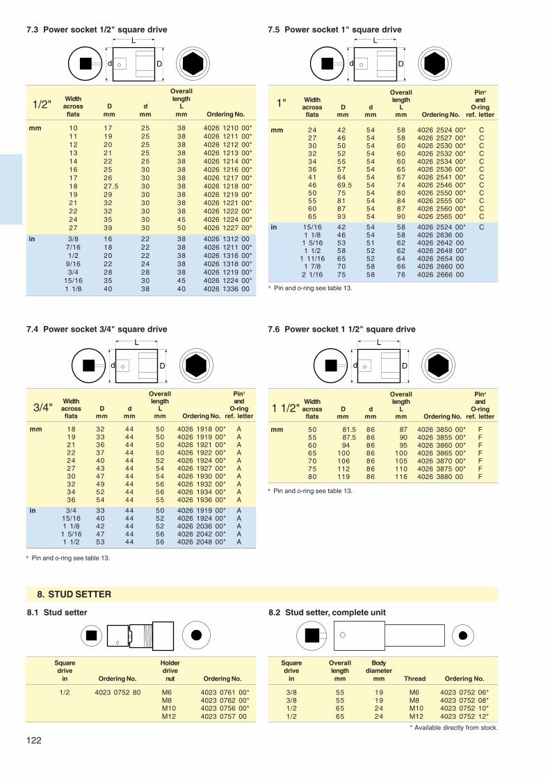
122
D
L
d D
L
d
D
L
d D
L
d
7.3 Power socket 1/2" square drive
OverallWidth lengthacross D d Lflats mm mm mm Ordering No.
mm 10 17 25 38 4026 1210 00*11 19 25 38 4026 1211 00*12 20 25 38 4026 1212 00*13 21 25 38 4026 1213 00*14 22 25 38 4026 1214 00*16 25 30 38 4026 1216 00*17 26 30 38 4026 1217 00*18 27.5 30 38 4026 1218 00*19 29 30 38 4026 1219 00*21 32 30 38 4026 1221 00*22 32 30 38 4026 1222 00*24 35 30 45 4026 1224 00*27 39 30 50 4026 1227 00*
in 3/8 16 22 38 4026 1312 007/16 18 22 38 4026 1211 00*1/2 20 22 38 4026 1316 00*
9/16 22 24 38 4026 1318 00*3/4 28 28 38 4026 1219 00*
15/16 35 30 45 4026 1224 00*1 1/8 40 38 40 4026 1336 00
7.4 Power socket 3/4" square drive
Overall Pina
Width length andacross D d L O-ringflats mm mm mm Ordering No. ref. letter
mm 18 32 44 50 4026 1918 00* A19 33 44 50 4026 1919 00* A21 36 44 50 4026 1921 00* A22 37 44 50 4026 1922 00* A24 40 44 52 4026 1924 00* A27 43 44 54 4026 1927 00* A30 47 44 54 4026 1930 00* A32 49 44 56 4026 1932 00* A34 52 44 56 4026 1934 00* A36 54 44 55 4026 1936 00* A
in 3/4 33 44 50 4026 1919 00* A15/16 40 44 52 4026 1924 00* A1 1/8 42 44 52 4026 2036 00* A
1 5/16 47 44 56 4026 2042 00* A1 1/2 53 44 56 4026 2048 00* A
Overall Pina
Width length andacross D d L O-ringflats mm mm mm Ordering No. ref. letter
mm 24 42 54 58 4026 2524 00* C27 46 54 58 4026 2527 00* C30 50 54 60 4026 2530 00* C32 52 54 60 4026 2532 00* C34 55 54 60 4026 2534 00* C36 57 54 65 4026 2536 00* C41 64 54 67 4026 2541 00* C46 69.5 54 74 4026 2546 00* C50 75 54 80 4026 2550 00* C55 81 54 84 4026 2555 00* C60 87 54 87 4026 2560 00* C65 93 54 90 4026 2565 00* C
in 15/16 42 54 58 4026 2524 00* C1 1/8 46 54 58 4026 2636 00
1 5/16 53 51 62 4026 2642 001 1/2 58 52 62 4026 2648 00*
1 11/16 65 52 64 4026 2654 001 7/8 70 58 66 4026 2660 00
2 1/16 75 58 76 4026 2666 00
7.5 Power socket 1" square drive
7.6 Power socket 1 1/2" square drive
Overall Pina
Width length andacross D d L O-ringflats mm mm mm Ordering No. ref. letter
mm 50 81.5 86 87 4026 3850 00* F55 87.5 86 90 4026 3855 00* F60 94 86 95 4026 3860 00* F65 100 86 100 4026 3865 00* F70 106 86 105 4026 3870 00* F75 112 86 110 4026 3875 00* F80 119 86 116 4026 3880 00 F
a Pin and o-ring see table 13.
8. STUD SETTER
8.1 Stud setter
Square Holderdrive drive
in Ordering No. nut Ordering No.
1/2 4023 0752 80 M6 4023 0761 00*M8 4023 0762 00*M10 4023 0756 00*M12 4023 0757 00
8.2 Stud setter, complete unit
Square Overall Bodydrive length diameter
in mm mm Thread Ordering No.
3/8 55 19 M6 4023 0752 06*3/8 55 19 M8 4023 0752 08*1/2 65 24 M10 4023 0752 10*1/2 65 24 M12 4023 0752 12*
* Available directly from stock.
a Pin and o-ring see table 13.
a Pin and o-ring see table 13.
1/2"
3/4"
1"
1 1/2"
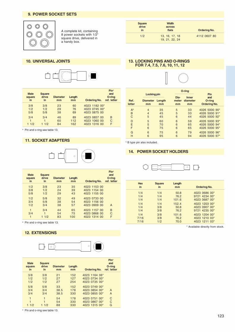
123
Pina
Male Square andsquare drive Diameter Length O-ring
in in mm mm Ordering No. ref. letter
3/8 3/8 21 152 4023 1164 06*1/2 1/2 27 127 4023 0734 00*1/2 1/2 27 254 4023 0735 00*
5/8 5/8 33 152 4023 0749 00*3/4 3/4 38.5 178 4023 0854 00* A3/4 3/4 38.5 330 4023 0855 00* A
1 1 54 178 4023 0751 00* C1 1 54 330 4023 0867 00* C
1 1/2 1 1/2 88 330 4023 1315 00* G
13. LOCKING PINS AND O-RINGSFOR 7.4, 7.5, 7.6, 10, 11, 12
O-ringLocking pin Pin
Dia- Inner andRef. Diameter Length meter diameter O-ring
letter mm mm mm mm Ordering No.
Ab 4 35 5 33 4026 5000 90*B 4 45 5 33 4026 5000 91*C 5 45 6 44 4026 5000 92*
D 5 60 6 59 4026 5000 93*E 5 70 6 65 4026 5000 94*F 6 75 6 65 4026 5000 95*
G 6 75 6 79 4026 5000 96*H 6 95 6 94 4026 5000 97*
a Pin and o-ring see table 13.
9. POWER SOCKET SETS
Square Widthdrive across
in flats Ordering No.
1/2 13, 16, 17, 18 4112 0607 8019, 21, 22, 24
10. UNIVERSAL JOINTS
Pina
Male Square andsquare drive Diameter Length O-ring
in in mm mm Ordering No. ref. letter
3/8 3/8 23 60 4023 1182 00*1/2 1/2 29 76 4023 0745 00*5/8 5/8 38 69 4023 0875 00
3/4 3/4 46 89 4023 0857 00 B1 1 60 112 4023 1060 00 C
1 1/2 1 1/2 84 162 4023 1316 00 F
11. SOCKET ADAPTERS
Pina
Male Square andsquare drive Diameter Length O-ring
in in mm mm Ordering No. ref. letter
1/2 3/8 23 35 4023 1153 003/8 1/2 24 39 4023 1154 005/8 1/2 29 43 4023 1155 00
1/2 5/8 32 49 4023 0733 003/4 5/8 38 54 4023 1156 001/2 3/4 38 57 4023 0909 00 A
1 3/4 44 65 4023 1157 00 B3/4 1 54 75 4023 0868 00 C1 1 1/2 83 100 4023 1314 00 F
12. EXTENSIONS
14. POWER SOCKET HOLDERS
Hex Square Lengthin in mm Ordering No.
1/4 1/4 50.8 4023 0686 00*1/4 1/4 76.2 9721 4234 00*1/4 1/4 101.6 4023 0687 00*1/4 1/4 152.4 4023 1203 00*1/4 3/8 50.8 4023 0907 00*1/4 3/8 76.2 9721 4235 00*1/4 3/8 101.6 4023 1204 00*
7/16 3/8 76.2 4023 1210 03*7/16 1/2 70.0 4023 1211 03*
a Pin and o-ring see table 13.
* Available directly from stock.
a Pin and o-ring see table 13.
A complete kit, containing8 power sockets with 1/2"square drive, delivered ina handy box.
b B type pin also included.

124
S L H
D
S L H
D D1
S L H
D
15. BITHOLDER FOR INSERT BITS
Square Hex Diameter LengthS H D Lin in Magnetic mm mm Ordering No.
3/8 1/4 No 19 33 4023 0793 00*3/8 5/16 No 19.9 33 4023 0948 00*1/2 1/4 No 22.1 37.8 4023 1446 06*1/2 5/16 No 23.8 38.1 4023 0725 00*
15.1 Type A
15.2 Type B
Square Hex Diameter LengthS H D Lin in Magnetic mm mm Ordering No.
1/4 1/4 No 12 25.2 4023 0695 00*
15.3 Type C
Square Hex Diameter LengthS H D D1 Lin in Magnetic mm mm mm Ordering No.
1/4 1/4a Yes 12.6 11.1 58 4023 1448 01*3/8 1/4 Yes 16.9 11.1 52.4 4023 1448 02*1/2 1/4 Yes 22.3 14.9 38.3 4023 1448 04
16. QUICK CHANGE CHUCK FOR POWER BITS
Square Femaledrive hex
in in Ordering No.
3/8 1/4 4023 1380 00*3/8 5/16 4023 1382 00*3/8 7/16 4023 1317 80*1/2 7/16 4023 0737 00*
* Available directly from stock.
a With front nut.

125
150
80300
2xcc100
4xØ8.5
2x125
B
500
A
200-250
300-310
100
TORQUE ARMS
SM A1 Parallel arm for 50 NmAtlas Copco torque arm SM A1 is an excellent means ofassistance when using hand-held straight or pistol grip toolse.g. screwdrivers, nutrunners, thread inserts etc.
The torque arms in the SM A1 series are made for heavyduty applications where the tool torque is limited to 50 Nm.
Tool weight should be in the range 1 to 4 kg. In order tobalance the tool weight in a proper and durable way the armsare equipped with gas spring cylinders.
A table stand is included as standard. Tool holder and tablestand clamp have to be ordered separately.
Description Ordering No.
Adjustable verticaltool holderØ 40-50 mm 4390 1735 07*Ø 50-60 mm 4390 1735 08*
Horizontal turnable tool holderØ 40-50 mm 4390 1735 09*Ø 50-60 mm 4390 1735 35
Description Ordering No.
Heavy duty 22-82 mmtable stand clamp 4390 1734 02*
Wall mounted standwith four 8.5 mmmounting holes 4390 1735 50
Table stand 800 mm 4390 1736 10
Tool weight Tool Tool Working rangeMax. torque diameter A B
Model kg Nm mm mm mm alfa Ordering No.
SM A1-400-2 1-2 50 40-60 0-400 600 360° 8202 9000 15*SM A1-400-3 2-3 50 40-60 0-400 600 360° 8202 9000 16*SM A1-400-4 2.5-4 50 40-60 0-400 600 360° 8202 9000 19*SM A1-500-2 1-2 50 40-60 0-500 700 360° 8202 9000 17*SM A1-500-3 1.5-3 50 40-60 0-500 700 360° 8202 9000 18*
OPTIONALTool holders and accessories for SM A1
(mm)SM A1
Accessories check list:• Tool holder?• Table stand clamp?
(mm)
* Available directly from stock.
!125-130.pmd 11/20/2003, 5:00 PM125

126
Max. 120
45
A
470
B
o
Max. 120 o
o
45o
2xcc84
2x100
4xØ8.5
TORQUE ARMS
Tool weight Tool Tool Working rangeMax. torque diameter A B
Model kg Nm mm mm mm alfa Ordering No.
SM S2-750 2.5 20 25-50 0-750 410 360o 8202 9000 12*SM S2-900 2.5 20 25-50 0-900 410 360o 8202 9000 21*
SM S2 Parallel arm for max 20 NmAtlas Copco torque arm SM S2 is an excellent means ofassistance when using hand-held straight or pistol grip toolse.g. screwdrivers, nutrunners, thread inserts etc.
Torque arm SM S2 is recommended when there is a lot offree space and a large working area is required. The SM S2 isexceptionally easy to position and handle. The design isintended for heavy duty operations over a long period of time.The open angle between jib and arm should not exceed 120°.
Tool weights should be in the range 0 to 2.5 kg. In order tohandle weights in the range 1-2.5 kg special springs aresupplied as standard.
A table stand is included as standard. Tool holder and tablestand clamp have to be ordered separately.
Description Ordering No.
Adjustable vertical tool holder
Ø 25-40 mm 4390 1734 04*Ø 40-50 mm 4390 1734 05*
Two-axis turnable tool holderwith adjustable turning torque
Ø 36 mm 4390 1734 06*Ø 38 mm 4390 1735 34*Ø 46 mm 4390 1734 07*Ø 56 mm 4390 1735 36*
Vertical extension for 4390 1735 46*SM A2/SM S2 700 mm
Vertical telescope extension 4390 1735 47for SM A2/SM S2400 mm-750 mm
Description Ordering No.
Horizontal turnable tool holderØ 36 mm 4390 1735 10*Ø 38 mm 4390 1735 03*Ø 46 mm 4390 1735 05*Ø 56 mm 4390 1735 37
Vertical tool holderØ 36 mm 4390 1735 04*Ø 38 mm 4390 1735 30*Ø 46 mm 4390 1735 00*Ø 56 mm 4390 1735 38*
OPTIONALTool holders and accessories for SM S2 and SM A2 (to be continued on page 127)
(mm)SM S2 (mm)
* Available directly from stock.
!125-130.pmd 11/20/2003, 5:00 PM126

127
B
470
A
cc150
2xcc84
2x100
4xØ8.5
TORQUE ARMS
SM A2 Parallel arm for max 20 NmAtlas Copco torque arm SM A2 is an excellent means of as-sistance when using hand-held straight or pistol grip toolse.g. screwdrivers, nutrunners, thread inserts etc.
Torque arms in the SM A2 series are recommended whenthere is a lot of equipment on the working bench and thespace is limited. The SM A2 is exceptionally easy to positionand handle. The design is intended for heavy duty operationsover a long period of time. Tool torque should not exceed 20Nm.
Tool weight should be in the range 0 to 2 kg for SM A2-300and 0 to 2.5 kg for SM A2-400.
A table stand is included as standard. Tool holder and tablestand clamp have to be ordered separately.
Tool weight Tool Tool Working rangeMax. torque diameter A B
Model kg Nm mm mm mm alfa Ordering No.
SM A2-Completea 2 20 25-40 0-300 400 360° 8202 9000 20*SM A2-300 2 20 25-50 0-300 400 360° 8202 9000 10*SM A2-400 2.5 20 25-50 0-400 450 360° 8202 9000 11*
a SM A2-Complete includes adjustable vertical tool holder Ø 25-40 mm and a heavy duty 22-82 mm table stand clamp.
Special adapters for Atlas Copcoscrewdrivers, see page 127.
Accessories check list:
• Tool holder?• Wall mounted stand?• Table stand clamp?• Special adapters?
OPTIONALTool holders and accessories for SM A2 and SM S2 (continued from page 126)
Description Ordering No.
Horizontal two-axisturnable tool holderØ 36 mm 4390 1735 11*Ø 38 mm 4390 1735 02*Ø 46 mm 4390 1735 06*Ø 56 mm 4390 1735 39
Heavy duty 22-82 mmtable stand clamp 4390 1734 02*
Description Ordering No.
Wall mounted stand with two8.5 mm mounting holes 4390 1734 01*
(mm)SM A2 (mm)
* Available directly from stock.
!125-130.pmd 11/20/2003, 5:00 PM127

128
cc80
2xØ8.5
800
500 mm
B
A
SM S3
2xcc84
2x100
TORQUE ARMS
SM S3 Parallel arm for max 3.5 Nm and large working areaAtlas Copco torque arm SM S3 is an excellent means ofassistance when using hand-held straight screwdrivers.
Torque arms SM S3 have a large working range and areexceptionally easy to position and handle. The design isintended for heavy duty operations over a long period of time.Tool torque should not exceed 3.5 Nm.
Tool weight should be in the range 0 to 1 kg. In order tohandle weights in the range 0.6-1 kg special springs aresupplied with the torque arm as standard. A wall mountingbracket is included as standard. Tool holder, table stand andtable stand clamp have to be ordered separately.
Tool weight Tool Tool Working rangeMax. torque diameter A B
Model kg Nm mm mm mm alfa Ordering No.
SM S3-750 1 3.5 25-50 0-700 400 180° 8202 9000 13*SM S3-900 1 3.5 25-50 0-850 550 180° 8202 9000 14*
OPTIONALTool holders and accessories for SM S3 (to be continued on page 129)
Description Ordering No.
Adjustable vertical tool holder
Ø 25-40 mm 4390 1735 12*Ø 40-50 mm 4390 1735 13
Two-axis turnable tool holderwith adjustable turning torque
Ø 36 mm 4390 1735 14Ø 38 mm 4390 1735 31Ø 46 mm 4390 1735 15*Ø 56 mm 4390 1735 40
Description Ordering No.
Heavy duty 22-82 mm 4390 1734 02*table stand clamp
Table stand with four 4390 1734 03*8.5 mm mounting holes
Special adapters for Atlas Copcoscrewdriver LUM25 PR-P, LUM10 PR andELI see page 127.
(mm)(mm)
* Available directly from stock.
!125-130.pmd 11/20/2003, 5:00 PM128
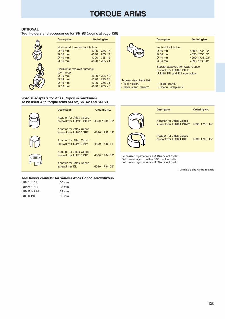
129
TORQUE ARMS
OPTIONALTool holders and accessories for SM S3 (begins at page 128)
Description Ordering No.
Horizontal turnable tool holderØ 36 mm 4390 1735 16Ø 38 mm 4390 1735 17Ø 46 mm 4390 1735 18Ø 56 mm 4390 1735 41
Horizontal two-axis turnabletool holderØ 36 mm 4390 1735 19Ø 38 mm 4390 1735 20Ø 46 mm 4390 1735 21Ø 56 mm 4390 1735 43
Description Ordering No.
Vertical tool holderØ 36 mm 4390 1735 22Ø 38 mm 4390 1735 32Ø 46 mm 4390 1735 23*Ø 56 mm 4390 1735 42
Special adapters for Atlas Copcoscrewdriver LUM25 PR-P,LUM10 PR and ELI see below:
Accessories check list:• Tool holder? • Table stand?• Table stand clamp? • Special adapters?
Special adapters for Atlas Copco screwdrivers.To be used with torque arms SM S2, SM A2 and SM S3.
Description Ordering No.
Adapter for Atlas Copcoscrewdriver LUM25 PR-Pa 4390 1735 01*
Adapter for Atlas Copcoscrewdriver LUM25 SRb 4390 1735 48*
Adapter for Atlas Copcoscrewdriver LUM12 PRc 4390 1736 11
Adapter for Atlas Copcoscrewdriver LUM10 PRa 4390 1734 09*
Adapter for Atlas Copcoscrewdriver ELIa 4390 1734 08*
Description Ordering No.
Adapter for Atlas Copcoscrewdriver LUM21 PR-Pa 4390 1735 44*
Adapter for Atlas Copcoscrewdriver LUM21 SRb 4390 1735 45*
a To be used together with a Ø 46 mm tool holder.b To be used together with a Ø 56 mm tool holder.c To be used together with a Ø 36 mm tool holder.
* Available directly from stock.
Tool holder diameter for various Atlas Copco screwdriversLUM21 HR-U 38 mm
LUM24B HR 38 mm
LUM25 HRF-U 38 mm
LUF20 PR 36 mm
!125-130.pmd 11/20/2003, 5:00 PM129
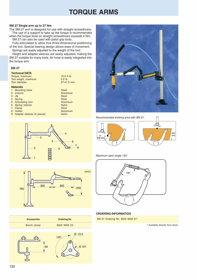
130
~250760305 305
60
120
Ø 101
Ø 10.4o
135 o
0 - 100 mm
400mm
3
2
1
9
5
4
6
78
TORQUE ARMS
SM 27 Single arm up to 27 NmThe SM 27 arm is designed for use with straight screwdrivers.
The use of a support to take up the torque is recommendedwhen the torque level on straight screwdrivers exceeds 4 Nm.
SM 27 can also be used with pistol grip tools.Fully-articulated to allow true three-dimensional positioning
of the tool. Special bearing design allows ease of movement.Springs are easily adjusted to the weight of the tool.Height and adapter sleeves are easily adjusted, making the
SM 27 suitable for many tools. Air hose is easily integrated intothe torque arm.
SM 27
Recommended working area with SM 27.
Maximum open angle 135o
(mm)
Technical DATATorque, maximum 19.9 ft lbTool weight, maximum 5.5 lbTool diameter 27-41.5 mm
Materials1 Mounting base Steel2 Column Aluminium3 Jib Steel4 Spring Steel5 Articulating arm Aluminium6 Spring retainer Nylon7 Clamp Steel8 Holder Aluminium9 Adapter sleeves (6 pieces) Delrin
ORDERING INFORMATION
SM 27 Ordering No. 8202 9000 01*
* Available directly from stock.
Accessories Ordering No.
Bench clamp 8202 9000 03
!125-130.pmd 11/20/2003, 5:00 PM130

Quality assurance –your competitive edge!
A loose or improperly tightened joint in any assemblyoperation can cause serious problems and have far-reach-ing consequences for end-users and manufacturers alike.
To ensure the right quality of your company’s products,Atlas Copco has developed a comprehensive quality assu-rance system to meet torque, angle and pulse measure-ment requirements for all types of fastening tools.
Contents PageACTA 3000 ............................................................... 132
ToolsTalk ACTA ......................................................... 132
IRTT transducers ...................................................... 133
QRTT transducers ....................................................133
SRTT transducers ....................................................134
MRTT transducers ............................................. 134-135
Torque testers ........................................................... 136
QualityAssurance in
Tightening

132
ACTA 3000
QUALITY ASSURANCE IN TIGHTENINGFor measuring and analysing torque
ACTA 3000The ACTA 3000 complemented by thePC program ToolsTalk ACTA providesyou with a complete tool database inwhich you have easy access to all the in-formation you need regarding torquemeasuring and analysing. The systemcuts tool administration costs and sys-tematically controls the status of yourtools during their entire life cycle. Itkeeps track of tightening data, calibra-tion data, service history, applicationanalyses, purchase details, supplier in-formation, etc. It controls and remindswhen it is time for tool calibration and/orpreventive maintenance (PM).All data stored per tool in one place!ACTA 3000 comes in three differentmodels and can be upgraded depend-ing on your needs:BasicMeasures torque and angle. You cancalibrate your tools and check basicstatistics.QC – Quality ControlCalculates all advanced statistics, in-cluding SPC, and has a database of upto 1000 tools/joints. This database in-cludes information regarding tool pro-gramming, tightening and events.AA – Advanced AnalysisIs the complete quality system. It offersall the above and shows an advancedtightening trace for joint analysis.
Model Ordering No.
ACTA 3000 – Basic 8092 1133 20ACTA 3000 – QC 8092 1133 30ACTA 3000 – AA 8092 1133 40
ToolsTalk ACTAThe PC program ToolsTalk ACTA com-pletes the quality assurance system tocalculate and provide all the informationyou want regarding your tools. InToolsTalk ACTA you manage your tools ina tool database, a tightening databaseand a supplier database. It enablesadvanced statistics/SPC and graphs.
Model Ordering No.
ToolsTalk ACTA Single PC 8092 1136 01ToolsTalk ACTA Network 5 users 8092 1136 05ToolsTalk ACTA Network 10 users 8092 1136 10ToolsTalk ACTA Network 20 users 8092 1136 20ToolsTalk ACTA Network 50 users 8092 1136 50
Cable included.Microsoft Windows NT4, 2000 or XP operating system.

133
IRTT
QRTT
NOTE: All IRTT are equipped with 19-pin connector.
Drive Rated capacity
Hex SquareModel in in Nm ft lb Ordering No.
Torque modelsIRTT 5-I06 1/4 5 4 8092 1129 05IRTT 20-I06 1/4 20 15 8092 1129 10IRTT 20-06 1/4 20 15 8092 1129 15IRTT 25-10 3/8 25 18 8092 1129 20IRTT 75-10 3/8 75 55 8092 1129 25IRTT 180-13 1/2 180 133 8092 1129 30IRTT 500-20 3/4 500 369 8092 1129 35IRTT 750-25 1 750 553 8092 1129 40IRTT 1400-25 1 1400 1033 8092 1129 45
Drive Rated capacity
Hex SquareModel in in Nm ft lb Ordering No.
Torque/angle modelsIRTT 1A-I06 1/2 1 0.8 8092 1130 96IRTT 2A-I06 1/2 2 1.5 8092 1130 01IRTT 5A-I06 1/4 5 4 8092 1130 06IRTT 20A-I06 1/4 20 15 8092 1130 11IRTT 20A-06 1/4 20 15 8092 1130 16IRTT 25A-10 3/8 25 18 8092 1130 21IRTT 75A-10 3/8 75 55 8092 1130 26IRTT 180A-13 1/2 180 133 8092 1130 31IRTT 500A-20 3/4 500 369 8092 1130 36IRTT 750A-25 1 750 553 8092 1130 41IRTT 1400A-25 1 1400 1033 8092 1130 46IRTT 3000A-25 1 3000 2200 8092 1130 51IRTT 5000A-38 1 1/2 5000 3685 8092 1130 56
IRTT – in-line rotary torque andtorque/angle transducersThe ACTA 3000 automatically reads thememory in Atlas Copco IRTT torque trans-ducers. No manual calibration is needed.The IRTT has very high readout accuracyand is available in torque or torque/angleversions.
QUALITY ASSURANCE IN TIGHTENINGFor measuring and analysing torque
DriveSquare For Rated capacity
Model in QMX spindle Nm ft lb Ordering No.
QRTT 20 Nm kit 3/8 42 2 - 20 1.5 - 15 8092 1164 13QRTT 75 Nm kit 3/8 42 7.5 - 75 5.5 - 55 8092 1164 18QRTT 200 Nm kit 1/2 50 20 - 200 15 - 150 8092 1164 23QRTT 500 Nm kit 3/4 62 50 - 500 37 - 369 8092 1164 28QRTT 1000 Nm kit 1 80, 90 100 -1000 75 - 750 8092 1164 33
QRTTTranducers used for QMX nutrunner aswell as for fixtured Tensor tool calibra-tion. This transducer enables an easyand fast set-up with highest systemaccuracy. By using the QRTT, no specialtest adaption device between the spindleand the product itself is needed.

134
MRTT
SRTT
Drive hex Capacity
Model in Nm ft lb Ordering No.
MRTT 2-I06 1/4 2.5 1.8 8092 1144 21MRTT 7-I06 1/4 7.5 5.5 8092 1144 26
QUALITY ASSURANCE IN TIGHTENINGFor measuring and analysing torque
MRTT – manual screwdriver torquetransducerThe MRTT screwdriver is designed tomeasure static torque on low torqueapplications. All MRTTs feature a built-in memory for fast auto-calibration withACTA 3000.
SRTT – static reaction torquetransducersThe static torque transducers are de-signed for fixturing where a rotary ac-tion is not desired during a measure-ment. All static torque transducers fea-ture a built-in memory for fast auto-cali-bration with ACTA 3000.
Square drive Capacity
Model in Nm ft lb Ordering No.
SRTT 0.5-06 1/4 0.5 0.4 8092 1143 15SRTT 2-06 1/4 2 1.5 8092 1143 20SRTT 5-06 1/4 5 4 8092 1143 25SRTT 25-10 3/8 25 18 8092 1143 30SRTT 75-13 1/2 75 55 8092 1143 35SRTT 180-13 1/2 180 133 8092 1143 40SRTT 500-20 3/4 500 369 8092 1143 45SRTT 1400-25 1 1400 1033 8092 1143 50
Range
Name Size Stiffness Nm ft lb Ordering No.
TJ SRTT H 25-10 3/8 Hard 25 18 4220 2451 80TJ SRTT S 25-10 3/8 Soft 25 18 4220 2451 81TJ SRTT H 75-10 1/2 Hard 75 55 4220 2659 80TJ SRTT S 75-10 1/2 Soft 75 55 4220 2659 81TJ SRTT H 180-13 1/2 Hard 180 133 4220 2660 80TJ SRTT S 180-13 1/2 Soft 180 133 4220 2660 81
Test joint for SRTT

135
MRTT
QUALITY ASSURANCE IN TIGHTENINGFor measuring and analysing torque
Square drive Capacity
Model in Nm ft lb Ordering No.
MRTT 25-06S 3/8 25 18 8092 1145 32MRTT 75-13S 1/2 75 55 8092 1145 37MRTT 180-13S 1/2 180 133 8092 1145 42MRTT-I 680-20S 3/4 680 510 8092 1164 52*
Length Ordering No.
1 m 4145 0963 013 m 4145 0963 035 m 4145 0963 05
Model Ordering No.
Industrial style Transducer cable 3 m 19 - 4 4145 0965 03Industrial style Transducer cable 3 m 19 - 6 4145 0968 03
* Transducer cable 3 m 19 - 6 4145 0966 03Industrial style Transducer cable 3 m 19 - 10 4145 0967 03
* Please contact Atlas Copco for specific details.
Transducer cableThe cable needed for all transducers(except MRTT screwdriver where cableis included).
For usage of non Atlas Copco transducersone of the following cables are required.
MRTT – manual wrench torquetransducerDesigned to measure static torque onhigher torque applications. The torquewrench features an LED indicator forlow/OK/high torque. It has a uniquesquare drive, which rotates free and islocked when pushed in.
* Works only with cable type 4145 0965 03

136
HT5TT30
Torque testers TT and HTTT – torque testersThe torque testers TT consist of an inte-grated torque transducer combined witha tightening analysis tool. The units aresuitable for clutch and impulse tools.The torque values are displayed in ei-ther Nm/in. lb. and are protected fromoverload by a mechanical stop. Thetesters of TT1 and TT10 type are idealfor calibrating screwdrivers. Test jointsare included.
a Optional accessories not valid for TT12 and TT30.
HT – torque testersThe HT units consist of a torque screw-driver combined with a tighteninganalysis tool. The analogue output canbe used together with a pen recorder,oscilloscope or voltmeter for various jointanalyses. Rechargeable NiCd cells powerthe testers.
Measure Accuracy Weightrange % of full Size
Model Nm scale mm kg lb Ordering No.
TTTT1 0 - 1.0 ±0.5 230x125x55 2.2 4.9 8092 1113 04TT10 0 - 10.0 ±0.5 230x125x55 2.2 4.9 8092 1113 12TT12a 2 - 12.0 ±0.5 162x240x112 3.5 7.7 8092 1101 73TT30a 6 - 30.0 ±0.5 162x240x112 3.5 7.7 8092 1101 81HTHT0.5 0 - 0.5 ±0.5 160x95x60 1.2 2.6 8092 1113 20HT5 0 - 5.0 ±0.5 160x95x60 1.2 2.6 8092 1113 38
Designation Ordering No.
Battery charger 220-240 VAC 4222 0162 00
Battery charger 110-120 VAC 4222 0162 01
Printer DP-1 HS 8092 1117 00
Printer cable 1 m 4222 0171 00
Connected to the DP-1 HS printer (op-tional) individual torque data and anumber of statistical calculations andcharts can be made.
NOTE: Not suitable for impact tools.
OPTIONAL ACCESSORIESFor more information see leaflet,Ordering No. 9833 1175 01.
QUALITY ASSURANCE IN TIGHTENINGFor measuring and analysing torque

119
Grinders
Safety first ................................................... 141
Turbo grinders and sanders .......................... 142
Die grinders .................................................. 146
Straight grinders ........................................... 148
Vertical grinders ........................................... 152
Angle grinders .............................................. 156
Angle sanders .............................................. 158
Orbital and random orbital sanders ............... 160
Dust extraction ............................................. 162
Routers ........................................................ 165
Nibbler ......................................................... 165
Circular cutters ............................................. 166
For a new experience, tryAtlas Copco Turbo Grinders
GTG21 and GTG40 Turbo Grinders give you twicethe power, with half the weight and they are im-possible to stall with the right installation! Theseare just two of the grinders in Atlas Copco´s widerange covering virtually all applications. With all ourgrinders, you can rely on maximum material rem-oval with minimum effort and, of course, higherproductivity.
Contents PageSelection guide ............................................ 138
Grinding at the right speed ........................... 140

138
2
1 Carbide burrs
Mounted points
8
7
6
5
3
Cut off wheels
Depressed centre wheels
Cup wheels
Flap wheels
Straight wheels
Cone wheels
4
SELECTION GUIDE
DIE GRINDING AND DEBURRING
ROUGH GRINDING AND CUTTING OFF
SANDING AND POLISHING
EXAMPLE: In a die grinding or engraving application, mounted points or rotary burrs are used. A suitabletool is the LSF straight die grinder, or the angle head type LSV die grinder.
WITH
WITH
WITH
14
13
11
Fibre discs
Coated abrasives
Wire brushes
Scotch-brite
Polishing bonnets
Radial flap wheels
9
10
12
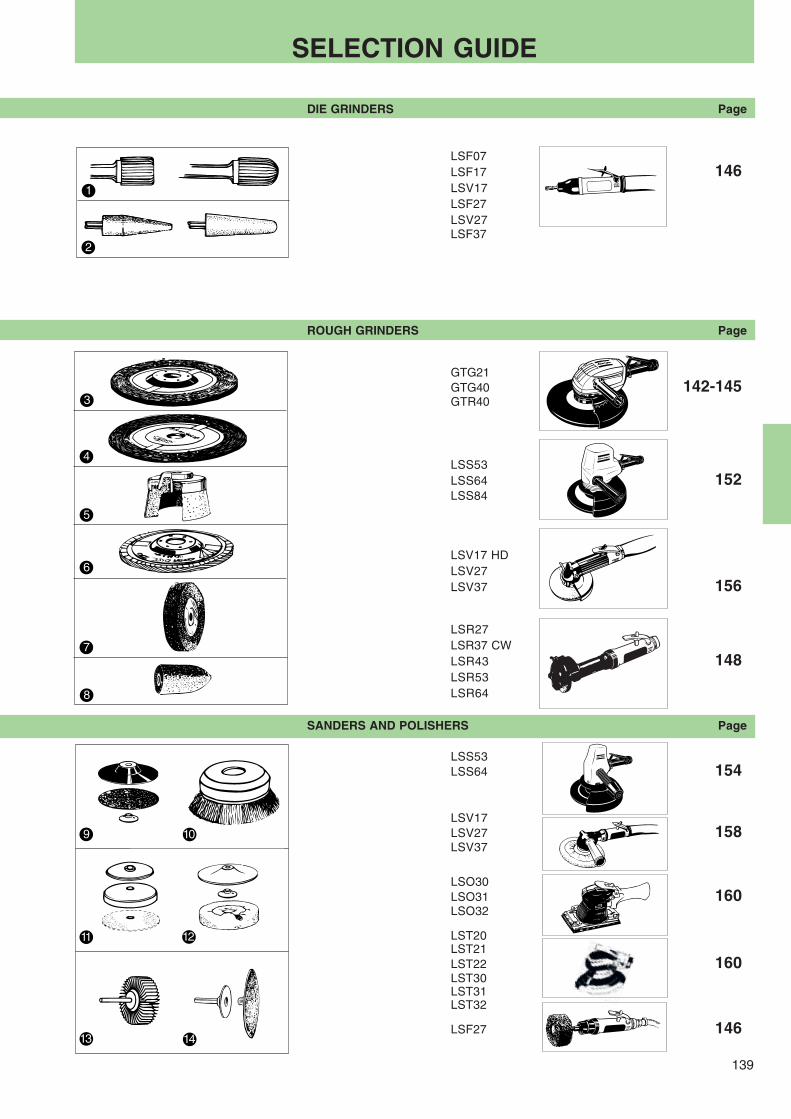
139
8
7
6
5
3
4
1413
11
9 10
12
2
1
SELECTION GUIDE
DIE GRINDERS Page
LSF07LSF17 146LSV17LSF27LSV27LSF37
ROUGH GRINDERS Page
GTG21GTG40 142-145GTR40
LSS53LSS64 152LSS84
LSV17 HDLSV27LSV37 156
LSR27LSR37 CWLSR43 148LSR53LSR64
SANDERS AND POLISHERS Page
LSS53LSS64 154
LSV17LSV27 158LSV37
LSO30LSO31 160LSO32
LST20LST21LST22 160LST30LST31LST32
LSF27 146
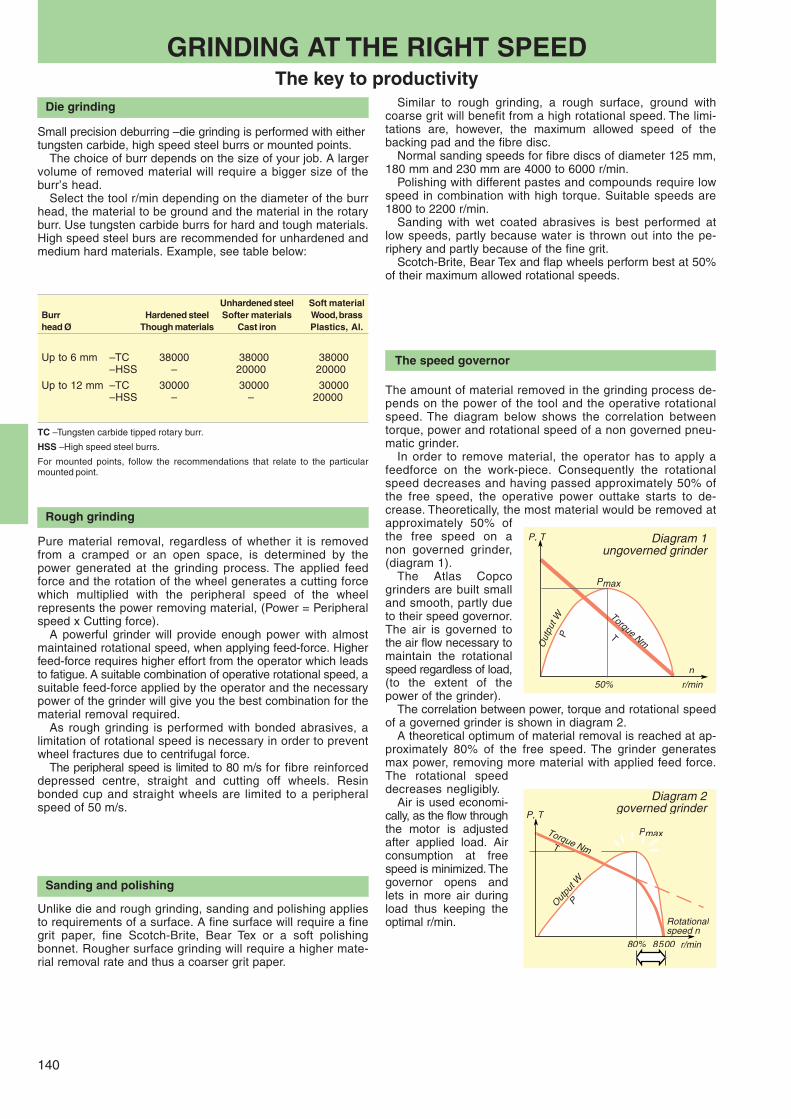
140
P, T
PmaxP
n
r/min50%
Torque NmT
ODiagram 1
ungoverned grinder
Die grinding
Small precision deburring – die grinding is performed with eithertungsten carbide, high speed steel burrs or mounted points.
The choice of burr depends on the size of your job. A largervolume of removed material will require a bigger size of theburr’s head.
Select the tool r/min depending on the diameter of the burrhead, the material to be ground and the material in the rotaryburr. Use tungsten carbide burrs for hard and tough materials.High speed steel burs are recommended for unhardened andmedium hard materials. Example, see table below:
GRINDING AT THE RIGHT SPEEDThe key to productivity
The speed governor
Similar to rough grinding, a rough surface, ground withcoarse grit will benefit from a high rotational speed. The limi-tations are, however, the maximum allowed speed of thebacking pad and the fibre disc.
Normal sanding speeds for fibre discs of diameter 125 mm,180 mm and 230 mm are 4000 to 6000 r/min.
Polishing with different pastes and compounds require lowspeed in combination with high torque. Suitable speeds are1800 to 2200 r/min.
Sanding with wet coated abrasives is best performed atlow speeds, partly because water is thrown out into the pe-riphery and partly because of the fine grit.
Scotch-Brite, Bear Tex and flap wheels perform best at 50%of their maximum allowed rotational speeds.
The amount of material removed in the grinding process de-pends on the power of the tool and the operative rotationalspeed. The diagram below shows the correlation betweentorque, power and rotational speed of a non governed pneu-matic grinder.
In order to remove material, the operator has to apply afeedforce on the work-piece. Consequently the rotationalspeed decreases and having passed approximately 50% ofthe free speed, the operative power outtake starts to de-crease. Theoretically, the most material would be removed atapproximately 50% ofthe free speed on anon governed grinder,(diagram 1).
The Atlas Copcogrinders are built smalland smooth, partly dueto their speed governor.The air is governed tothe air flow necessary tomaintain the rotationalspeed regardless of load,(to the extent of thepower of the grinder).
The correlation between power, torque and rotational speedof a governed grinder is shown in diagram 2.
A theoretical optimum of material removal is reached at ap-proximately 80% of the free speed. The grinder generatesmax power, removing more material with applied feed force.The rotational speeddecreases negligibly.
Air is used economi-cally, as the flow throughthe motor is adjustedafter applied load. Airconsumption at freespeed is minimized. Thegovernor opens andlets in more air duringload thus keeping theoptimal r/min.
Sanding and polishing
Unlike die and rough grinding, sanding and polishing appliesto requirements of a surface. A fine surface will require a finegrit paper, fine Scotch-Brite, Bear Tex or a soft polishingbonnet. Rougher surface grinding will require a higher mate-rial removal rate and thus a coarser grit paper.
Rough grinding
Pure material removal, regardless of whether it is removedfrom a cramped or an open space, is determined by thepower generated at the grinding process. The applied feedforce and the rotation of the wheel generates a cutting forcewhich multiplied with the peripheral speed of the wheelrepresents the power removing material, (Power = Peripheralspeed x Cutting force).
A powerful grinder will provide enough power with almostmaintained rotational speed, when applying feed-force. Higherfeed-force requires higher effort from the operator which leadsto fatigue. A suitable combination of operative rotational speed, asuitable feed-force applied by the operator and the necessarypower of the grinder will give you the best combination for thematerial removal required.
As rough grinding is performed with bonded abrasives, alimitation of rotational speed is necessary in order to preventwheel fractures due to centrifugal force.
The peripheral speed is limited to 80 m/s for fibre reinforceddepressed centre, straight and cutting off wheels. Resinbonded cup and straight wheels are limited to a peripheralspeed of 50 m/s.
PmaxP
Rotationalspeed n
r/min80%
Torque NmT
8500
P, T
Outpu
t W
P
Diagram 2governed grinder
TC – Tungsten carbide tipped rotary burr.
HSS – High speed steel burrs.
For mounted points, follow the recommendations that relate to the particularmounted point.
Unhardened steel Soft materialBurr Hardened steel Softer materials Wood, brasshead Ø Though materials Cast iron Plastics, Al.
Up to 6 mm – TC 38000 38000 38000– HSS – 20000 20000
Up to 12 mm – TC 30000 30000 30000– HSS – – 20000

141
Check that flange and wheelcombinations correspond to nationalregulations. Check that the flanges areundamaged and that they are clean.
Wear– personal protection goggles– ear protection– gloves (helmet in heavier applications)
Test run your grinder in aprotected area after havingassembled the wheel
Keep the space around the grinding op-eration free from other people.
MaintenanceMake sure to follow prescribed service in-structions and intervals. Do not disassem-ble security parts, e.g. speed governor oroverspeed shut-off. These parts have tobe completely replaced when damaged.
Check the free speedThe measured speed at a pressure of 6.3bars should not exceed the rated speed ofthe grinder. A tolerance of +10% is accept-able if stated in the documentation of thetool. The wheel must be removed beforethe grinder is checked. The checks shouldbe carried out regularly, especially afterlonger standstill. Make sure that the speedmarking on the tool is readable.
Check the wheelguardAlways use the recommended wheel-guardand check that it is not damaged. Neveruse a grinder without the wheelguard whenthe grinding wheel requires one.
Match the maximum speed ofthe wheel to the right grinder
Make sure that the stated maximum speedof the grinder never exceeds the maximumspeed of the grinding wheel.
Check the grinding wheelMake sure that the grinding wheel is notcracked or damaged in any way. The grind-ing wheel should have the correct hole di-mensions and should be fitted properly onthe spindle to avoid unbalanced vibrations.
This is your responsibilityThere are, however, measures the operator has to take in or-der to avoid any risk of misuse or accident. The safety manual,supplied with every grinder contains a number of safety rulesfor the operator. The 8 steps below are a basic summary of thesafety manual. But read the safety manual as well.
Built-in safetyThe Atlas Copco grinders feature a high degree of built-insafety. Overspeed shut-off, safety throttles and wheel guardsare good examples of product safety features carried by ourgrinders.
Performance checkedEvery grinder leaving our factory is checked on maximumfree speed and general functions.
Diameter – Peripheral speed – r/minThe table below will help you to translate the peripheral speed of the grinding wheel to the right rotational speed of the grinderwhen using a specific diameter of grinding wheel.
Grinding wheel Peripheral speed in metres per seconddiametermm 10 15 20 25 28 30 33 35 40 45 48 50 60 80
25 7640 11460 15280 19100 21390 22920 25210 26740 30560 34380 36670 38200 45840 6112040 4770 7160 9550 11930 13370 14320 15750 16710 19100 21480 22920 23870 28650 3820050 3820 5730 7640 9550 10690 11460 12600 13370 15280 17190 18330 19100 22920 3056063 3303 4540 6060 7560 8480 9090 10000 10610 12120 13640 14550 15150 18190 24250
80 2380 3580 4770 5960 6680 7160 7870 8350 9550 10740 11460 11930 14320 19100100 1910 2860 3820 4770 5340 5730 6300 6680 7640 8590 9160 9550 11460 15280115 1160 2490 3320 4150 4650 4980 5480 5810 6640 7470 7970 8300 9960 13400125 1520 2290 3050 3820 4270 4580 5040 5340 6110 6870 7330 7640 9160 12280
150 1270 1910 2540 3180 3560 3820 4200 4450 5090 5730 6110 6360 7640 10180180 1060 1590 2120 2650 2970 3180 3500 3710 4240 4770 5090 5300 6360 8480200 950 1430 1910 2380 2670 2860 3150 3340 3820 4290 4580 4770 5730 7640230 830 1240 1660 2070 2320 2490 2740 2900 3320 3730 3980 4150 4980 6640
250 760 1140 1520 1910 2130 2290 2520 2670 3050 3430 3660 3820 4580 6110300 630 950 1270 1590 1780 1910 2100 2220 2540 2860 3050 3180 3820 5090
SAFETY FIRST
HOW TO MAKE IT SAFER
1
2
3
4
5
6
7
8

142
GTG21 S085
GTG21 F120-13
GTG21 F085-18
GTG21 S085D
Twice the power. Half the weight. TheTurbo grinder gives you twice the powerof today’s 5", 7" and 9" angle grinders. Itis about half the size and weight of highfrequency tools with comparable power.❏ High material removal – The Turbo is
powerful and keeps on working athigh rotational speed. It gives ahigher rate of cutting-off or materialremoval, with low wheel consumption.
❏ Power for efficiency – The Turbo isdriven by an turbine motor, providingpower-to-weight ratios never beforeachieved in grinders. This means youcan choose a lighter, more compacttool for ease of use and good accessi-bility without sacrificing any of thepower.
❏ Long service life – The turbine meansthere are no vanes to slide againstthe cylinder. The gear runs in oil in ahousing with patented seals. Theresult is consistent performance andinterruption free operation.
❏ Minimized vibrations – on the Turbo,vibration has been cut to below 2.5m/s2. This has been achieved by anentirely new vibration-damping tech-nique, Auto Balancing, in which a setof bearing balls is used to counter-balance the imbalance in the wheel.
❏ Lubrication-free – The unique tur-bine drive in the Turbo means that themotor doesn’t need oil in the air forlubrication. This provides several ben-efits from the points of views ofworking environment, quality andproductivity.
❏ Dust extraction – Efficient accessoryand standard model for extraction ofair-borne dust in sanding applicationswith fibre discs.
Max Max Height over Air consumption at Air Sound levelfree wheel Max output Weight spindle end max output free speed Hose size inlet at free
speed dia thread speedModel r/min mm kW hp kg lb mm in l/s cfm l/s cfm mm in BSP dB(A) Ordering No.
For grinding and cuttingGTG21 F120-13 12000 125 2.1 2.8 1.8 3.9 68 2.7 30 64 10 21 13 1/2 3/8 74 8423 2963 00*GTG21 F085-18 8500 180 2.1 2.8 2.0 4.2 72 2.8 30 64 10 21 13 1/2 3/8 74 8423 2963 02*
For sandingGTG21 S085a 8500 180 2.1 2.8 2.0 4.4 80 3.1 30 64 10 21 13 1/2 3/8 74 8423 2963 05*GTG21 S085-Db 8500 180 2.1 2.8 2.4 5.3 94 3.7 30 64 10 21 13 1/2 3/8 74 8424 2963 09*GTG21 S085 M14 8500 180 2.1 2.8 1.6 3.5 80 3.1 30 64 10 21 13 1/2 3/8 74 8423 2963 07
a UNC 5/8"-11 spindle.b With dust extraction – for sanding applications with fibre dis cs. Flow requirement 250 m3/h.
TURBO GRINDERS AND SANDERS
Process time
Total air consumption
Conventional air grinder Turbo air grinder
MORE EFFECTIVEGTG21 is the newest of the Turbogrinders. It is the best choice for roughgrinding and sanding applications.
The turbine motor is more efficient than aconventional grinder motor. It thereforetakes less time to do the same job. Alsothe total air consumption will be a lot lessfor a specific job.
* Available directly from stock.

143
1
1
12
GTG21 S085D 2
TURBO GRINDERS AND SANDERSCompact, powerful and efficient
ACCESSORIESINCLUDED – GTG21
All modelsAdjustable support handleWhip hose 0.7 m long, 13 mm diacomlete with nipple and ErgoNip 10Gear box oil, one tube
GTG21 F120/F085Adjustable wheel guardAttachment flanges for 1-10 mmthick grinding wheelsHex key for wheel change
GTG21 S085DFlow chamberSuction capSupport pad dia 180 mm
SERVICE KIT4081 0220 90
OPTIONAL ACCESSORIES – GTG21
Spindle adapter kit for sanding with GTG21 grinder
Air hose set for maximum performance Ordering No.
RUBAIR 13, L=5 m, incl ErgoNIP 10, ErgoQIC 10 8202 1180 22
Air preparation unit, incl MIDI F/R, ball valve ErgoQIC 10 8202 0845 48
TURBO 16, L=10 m, incl ErgoNIP 10, ErgoQIC 10 8202 1180 46
Support pad dia Ordering No.Sanding kit for mm 5/8 M14
GTG21 F120-13 120 4175 0883 92 4175 0883 93
GTG21 F085-18 162 4175 0883 90 4175 0883 91
The rearexhaust.
The spindle lock enables simple wheelchange.
Adjustable support handle,using same key as for wheelnut. Lubrication-free turbine motor.
Angled design optimizes the grindingangle for a natural working position.
Integrated autobalancer reduces vibrationsto level below 2.5 m/s2.
Low height over angle head.
Oil-lubricated angle gear.
Locking lever.
Comfortable handle with soft grip.
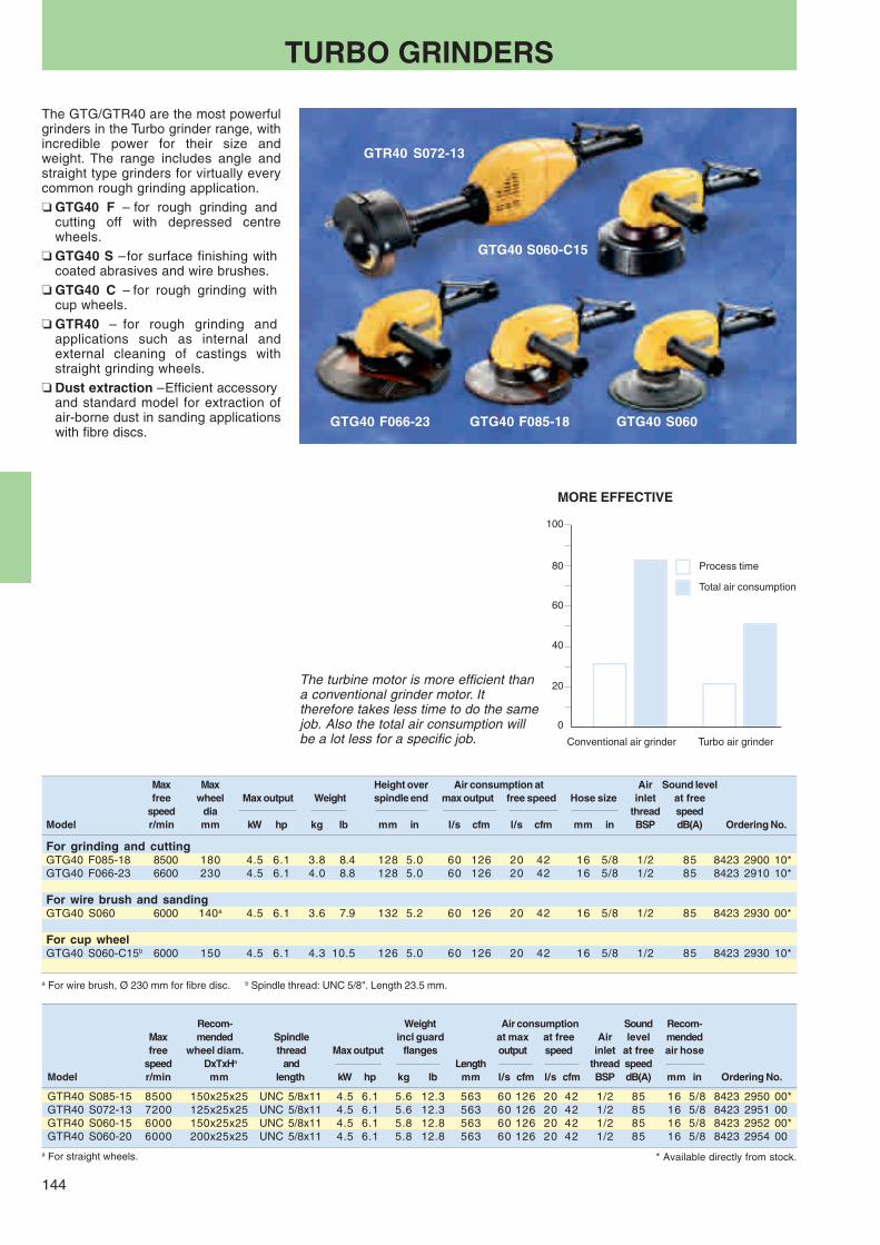
144
GTR40 S072-13
GTG40 F066-23 GTG40 S060GTG40 F085-18
GTG40 S060-C15
TURBO GRINDERS
Max Max Height over Air consumption at Air Sound levelfree wheel Max output Weight spindle end max output free speed Hose size inlet at free
speed dia thread speedModel r/min mm kW hp kg lb mm in l/s cfm l/s cfm mm in BSP dB(A) Ordering No.
For grinding and cuttingGTG40 F085-18 8500 180 4.5 6.1 3.8 8.4 128 5.0 60 126 20 42 16 5/8 1/2 85 8423 2900 10*GTG40 F066-23 6600 230 4.5 6.1 4.0 8.8 128 5.0 60 126 20 42 16 5/8 1/2 85 8423 2910 10*
For wire brush and sandingGTG40 S060 6000 140a 4.5 6.1 3.6 7.9 132 5.2 60 126 20 42 16 5/8 1/2 85 8423 2930 00*
For cup wheelGTG40 S060-C15b 6000 150 4.5 6.1 4.3 10.5 126 5.0 60 126 20 42 16 5/8 1/2 85 8423 2930 10*
Recom- Weight Air consumption Sound Recom-Max mended Spindle incl guard at max at free Air level mendedfree wheel diam. thread Max output flanges output speed inlet at free air hose
speed DxTxHa and Length thread speedModel r/min mm length kW hp kg lb mm l/s cfm l/s cfm BSP dB(A) mm in Ordering No.
GTR40 S085-15 8500 150x25x25 UNC 5/8x11 4.5 6.1 5.6 12.3 563 60 126 20 42 1/2 85 16 5/8 8423 2950 00*GTR40 S072-13 7200 125x25x25 UNC 5/8x11 4.5 6.1 5.6 12.3 563 60 126 20 42 1/2 85 16 5/8 8423 2951 00GTR40 S060-15 6000 150x25x25 UNC 5/8x11 4.5 6.1 5.8 12.8 563 60 126 20 42 1/2 85 16 5/8 8423 2952 00*GTR40 S060-20 6000 200x25x25 UNC 5/8x11 4.5 6.1 5.8 12.8 563 60 126 20 42 1/2 85 16 5/8 8423 2954 00
* Available directly from stock.a For straight wheels.
a For wire brush, Ø 230 mm for fibre disc. b Spindle thread: UNC 5/8". Length 23.5 mm.
The GTG/GTR40 are the most powerfulgrinders in the Turbo grinder range, withincredible power for their size andweight. The range includes angle andstraight type grinders for virtually everycommon rough grinding application.❏ GTG40 F – for rough grinding and
cutting off with depressed centrewheels.
❏ GTG40 S – for surface finishing withcoated abrasives and wire brushes.
❏ GTG40 C – for rough grinding withcup wheels.
❏ GTR40 – for rough grinding andapplications such as internal andexternal cleaning of castings withstraight grinding wheels.
❏ Dust extraction – Efficient accessoryand standard model for extraction ofair-borne dust in sanding applicationswith fibre discs.
Process time
Total air consumption
The turbine motor is more efficient thana conventional grinder motor. Ittherefore takes less time to do the samejob. Also the total air consumption willbe a lot less for a specific job. Conventional air grinder Turbo air grinder
MORE EFFECTIVE

145
1
3
2c
2a
2b
1 2
1
2
ACCESSORIES INCLUDED – GTG40Adjustable wheel guardSupport handleAttachments flanges for 1.5-7 mm thick cut-off wheels and 2.5-8 mmthick depressed centre wheelsWhip hose 0.7 m long, 16 mm dia complete with nipple and ErgoNIP 10Gear box oil, one tubeHex key for wheel change
OPTIONAL ACCESSORIES – GTG40
GTR40
ACCESSORIES INCLUDED – GTR40Wheel guardAttachments flanges for grinding wheels 20-32 mm thick and withhole Ø 25 mmWhip hose 0.7 m long, 16 mm dia complete with nipple and ErgoNIP 10Gear box oil, one tubeKey and spanner for wheel change
OPTIONAL ACCESSORIES – GTR40
Thickness x Hole diamm Ordering No.
2 Rear flange TxH 20-32x 16 2a 4150 0619 00x 20 2b 4150 1650 00x 32 2c 4150 0620 00
3 Spacer for cone wheel 3 4150 0787 00
OPTIONAL ACCESSORIES GTG40 and GTR40Air hose sets for maximum performance
Air hose set Length Air pressure Ordering No.
Fixed installation 5 m, Ø 16 mmTURBO 16/5 M/CLAW 5 m <6 bar 8202 1181 95
Flexible installation 5 m, Ø 16 mmb
TURBO 16/5 M/EQ 10 5 m >6 bar 8202 1181 80
Flexible installation 20 m, Ø 19 mmb
TURBO 20/20 M/EQ 10 20 m >6 bar 8202 1181 75
Air preparation unit, including MAXI F/R 25 with ball valveand claw coupling 8202 0845 74
b Whip hose 0.5 m included as standard in GTG/GTR40.
For technical details and other dimensions, see page 241.
TURBO GRINDERSTwice the power. Half the weight
SERVICE KITS
GTG40 4081 0153 90GTR40 4081 0153 91
Adapter
Hand shield
Back-up pad
Turbine motor.
Servo-controlled governor andoverspeed shut-off valve. Speed marking clearly visible.
Silencer.
Wheel guard, easily adjustable.
Quick release flange for easy changeof wheel.
Throttle handle withsolft rubber for
comfortable grip andtemperature
insulation.
Gear lubricated with oil forlonger service life.
Vibration damping withAuto Balancing.
Ordering No.
Wire brush Ø 140 mm 4170 0685 00Wire brush attachment set 4170 0550 82Adjustable support handle 4170 0619 81Heavy duty backing pad for sanding Ø 180 mm (7") 4170 1192 90
Ø 230 mm (9") 4170 1193 90Hand shield 4175 0165 90Adaptor for positioning support handle 120/135o
between handles 4175 0164 90*Dust extraction kita for 180 mm fiber disc GTG40 S060 3780 4090 10Hose kit including 1.8 m vacuum hose, Ø 38 mm andair hose Ø 13 mm 3780 2724 41Friction plate complete 4175 0186 90
a Incl flow chamber, suction cap and support pad.* Included as standard in GTG40 S060-C15.

146
LSF27 ST-E
LSF37 E
LSF17 E
LSF17
LSF27
LSV17-1 HD
LSF27 E
DIE GRINDERS
The Atlas Copco governed die grindersoffer the very best of productivity, reli-ability and ergonomics.❏ Best performance, low weight – The
speed governor keeps the rotationalspeed close to the maximum freespeed when feed-force is applied.The use of a speed governor enablesa smaller and smoother design whilemaintaining access to power.
❏ Built-in ergonomics for the bestworking environment – The uniquesuspension of motor and spindle ofthe LSF series prevent unpleasant vi-brations from being transferred to theoperator’s hand. Well tuned motors andair outlet keep sound levels very low.
❏ Minimized burr consumption – Asuspension of the spindle preventsthe burr from chattering. Apart from asmoother die grinding operation, theburr consumption is minimized, inmany applications by 20%.
❏ Wide range – You can choose thesuitable model for your application –from heavy duty versions to small, an-gle die grinders. Short and extendedmodels (E).
❏ LSF27 ST030 is lubrication-free – forclean environment.
❏ LSF-R, these models have a rigid shaftsuspension. Recommended for moun-ted points.
❏ LSF37 – 1000 Watt powerful motorfor the toughest applications. Twomodels are lubrication-free.
Rec max dia of
Tungsten Air consumption Recom- SoundMax car- Mount- Max at max at free mended Air level Ordering No.free bide ed output Weight output speed air hose inlet at free with collet
speed burrs point Length thread speedModel r/min mm mm kW hp kg lb mm l/s cfm l/s cfm mm in BSP dB(A) 6 mm 1/4"
Die grinders – Straight modelsLSF17 S430 43000 9 16 0.30 0.40 0.4 0.9 170 9 19 10 21 8 5/16 1/4 75 8423 1224 27* 8423 1224 50LSF17 S430E 43000 9 16 0.30 0.40 0.6 1.3 270 9 19 10 21 8 5/16 1/4 75 8423 1225 26*LSF17 S430E/R 43000 9 16 0.30 0.40 0.6 1.3 270 9 19 10 21 8 5/16 1/4 75 8423 3111 03*LSF17 S300 30000 12 20 0.28 0.38 0.4 0.9 170 9 19 6 13 8 5/16 1/4 73 8423 1224 19* 8423 1224 43*LSF17 S300-1/R 30000 12 20 0.28 0.38 0.4 0.9 170 9 19 6 13 8 5/16 1/4 73 8423 1231 69*LSF17 S300E 30000 12 20 0.28 0.38 0.6 1.3 270 9 19 6 13 8 5/16 1/4 73 8423 1225 18*LSF17 S300E/R 30000 12 20 0.28 0.38 0.6 1.3 270 9 19 6 13 8 5/16 1/4 73 8423 3111 01*LSF17 S200 20000 12 20 0.25 0.34 0.4 0.9 170 8 17 4 8 8 5/16 1/4 64 8423 1224 01* 8423 1224 35*LSF17 S200E 20000 12 20 0.25 0.34 0.6 1.3 270 8 17 4 8 8 5/16 1/4 64 8423 1225 00*LSF27 S250 25000 12 32 0.65 0.87 0.7 1.5 205 18 38 13 27 10 3/8 3/8 75 8423 1235 10* 8423 1235 36LSF27 S250/R 25000 12 32 0.65 0.87 0.7 1.5 205 18 38 13 27 10 3/8 3/8 75 8423 1235 51*LSF27 S250E 25000 12 32 0.65 0.87 1.2 2.6 330 18 38 13 27 13 1/2 3/8 75 8423 1236 19*LSF27 S250E/R 25000 12 32 0.65 0.87 1.2 2.6 330 18 38 13 27 13 1/2 3/8 75 8423 1235 50*LSF27 S180 18000 16 40 0.65 0.87 0.7 1.5 205 16 34 7 15 10 3/8 3/8 69 8423 1235 02* 8423 1235 28LSF27 S180/R 18000 16 40 0.65 0.87 0.7 1.5 205 16 34 7 15 10 3/8 3/8 69 8423 1235 44*LSF27 S180E 18000 16 40 0.65 0.87 1.2 2.6 330 16 34 7 15 13 1/2 3/8 69 8423 1235 03* 8423 1235 27LSF27 S180E/R 18000 16 40 0.65 0.87 1.2 2.6 330 16 34 7 15 13 1/2 3/8 69 8423 1235 43*LSF27 S150 15000 16 40 0.60 0.80 0.7 1.5 205 15 32 6 13 10 3/8 3/8 66 8423 1235 76*LSF27 S150E 15000 16 40 0.60 0.80 1.2 2.6 330 15 32 6 13 13 1/2 3/8 66 8423 1235 84*LSF27 S120 12000 16 40 0.60 0.80 0.7 1.5 205 14 30 4 8 10 3/8 3/8 65 8423 1235 68*LSF37 S250E 25000 12 32 1.0 1.3 1.9 4.2 346 23 49 21 45 13 1/2 3/8 84 8423 1232 25*LSF37 S180E-LF 18000 16 40 1.0 1.3 1.9 4.2 346 22 49 13 27 13 1/2 3/8 78 8423 1232 17*LSF37 S180E-LF/R 18000 16 40 1.0 1.3 1.9 4.2 346 22 47 13 28 13 1/2 3/8 78 8423 1232 16*LSF37 S150E-LF 15000 16 40 1.0 1.3 1.9 4.2 346 20 42 9 19 13 1/2 3/8 78 8423 1232 15*
Angle grindersLSV17 S200-1HD 20000 12 20 0.25 0.34 0.7 1.5 197 9 19 7 15 8 5/16 1/4 75 8423 0111 17*LSV27 S150 15000 16 40 0.57 0.76 1.1 2.4 245 15 32 8 17 10 3/8 3/8 78 8423 0125 56*
Die grinders for polishingLSF27 ST070 7000 – – 0.65 0.87 1.0 2.2 270 17 36 10 42 10 3/8 3/8 75 8423 1235 69*LSF27 ST070-E 7000 – – 0.65 0.87 1.7 2.2 395 17 36 10 42 10 3/8 3/8 75 8423 1235 70*LSF27 ST030-LF 3000 – – 0.60 0.80 1.0 2.2 270 16 34 10 42 10 3/8 3/8 73 8423 1235 79*LSF27 ST030LF-E 3000 – – 0.60 0.80 1.7 2.2 395 16 34 10 42 10 3/8 3/8 73 8423 1235 80*
E = Extended version, flexible spindleR = Rigid model
* Available directly from stock.HD = Heavy dutyLF = Lubrication-free

147
LSF17
LSF17 E
LSF27
LSF27 E
1
1
1
1
3
3
3
3
2
2
4
4
4
4
LSF07
1
2
3 4OPTIONAL collets
Dia Ordering No.
LSF17/27/36 3 mm 4150 0081 00 6 mm 4150 0075 00 8 mm 4150 0074 001/8" 4150 0082 005/32" 4150 0648 003/16" 4150 0649 001/4" 4150 0076 005/16" 4150 0074 00Collet nut 4150 0760 00
LSF37 6 mm 4150 1453 00 8 mm 4150 0706 0010 mm 4150 0681 001/4" 4150 1754 00Collet nut 4150 0849 00
Spindle extension for R-modelsSpindle extensionis optional Ordering No.
Length 75 mm / 3 inches 4150 0674 00
OPTIONALFor machining reinforced plastics
For die grinders LSF17 Dia mm LSF27 Dia mm
Diamond burr 3780 5013 70 6 3780 5014 20 8Diamond drum 3780 5033 00 27 3780 5035 00 50Spot suction kit for burr 3780 3015 20 3780 4007 41Spot suction kit for drum 3780 4011 60 6 (shaft) 3780 4011 71 8 (shaft)
ACCESSORIES INCLUDEDSpannerCollet 6 mm (LSF37 6- and 8 mm)Air hose, air hose nipple and clampExhaust hose
Front exhaust – Modification kitModel Ordering No.
LSF17 short model 4150 1031 91
ACCESSORIES
SERVICE KITS
07 series 4081 0243 9017 series 4081 0026 9027 series 4081 0130 9037 series 4081 0249 90
DIE GRINDERS
❏ High speed model – LSF07 is a newhigh speed model for precise grindingand polishing at die making and e.g.renovation of air craft engines.
ACCESSORIES INCLUDEDAir hose and ErgoNIP 08 included Ø 3 mmcollet and collet wrench. Exhaust withsilencer (LSF07).
Rec max dia of
Tungsten Air consumption Recom- SoundMax car- Mount- Max at max at free mended Air levelfree bide ed output Weight output speed air inlet at free
speed burrs point Length hoseb thread speed Ordering No.Model r/min mm mm kW hp kg lb mm l/s cfm l/s cfm mm BSP dB(A) with colleta
High speed modelLSF07 S850 88000 4 6 0.10 0.13 0.4 0.9 170 2.2 4.9 2.3 4.6 4.5 – 79 8423 1222 03*
OPTIONAL ACCESSORIESØ 1/8" collet 4150 1822 00
a Ø 3 mm collet standard.b Air hose and ErgoNIP included.
* Available directly from stock.

148
LSR27 CW
LSR43-30C
LSR37 CW
STRAIGHT GRINDERSFor cone wheels, plugs and collet
Internal grinding of holes and cavities incastings, etc. require rough abrasives,which must be attached to the tool with arigid shank or be mounted directly on thespindle.❏ Rigid and powerful for best produc-
tivity – The rigid LSR43 series givesyou the outmost power for the rough-est tasks of internal grinding.
❏ Built-in ergonomics for workingcomfort – Lighter jobs are success-fully done with LSR27/37. These lightand handy tools offer low sound andvibration levels and will spare your op-erator.
❏ Lubrication-free – The LSR37-modelsare lubrication-free.
a LSR27/37 measured with exhaust hose (incl. accessories). For LSR43, the sound level can be reduced8-12 dB(A) by using a silencer (optional accessories).
-CW indicates use for cone wheel or collet, thread M12x1 to be combined with adaptor for wheel thread.-LF = Lubrication-free motor.-30C, 6 mm collet is included.-30 indicates use for cone wheel or collet, thread M12x1 to be combined with adaptor for wheel thread.
* Available directly from stock.
Air consumption Recom- SoundMax Max at max at free Air mended levela
free output Weight output speed inlet air hose at freespeed Length thread speed
Model r/min kW hp kg lb mm l/s cfm l/s cfm BSP mm in dB(A) Ordering No.
Straight grindersLSR27 S150-CW 15000 0.60 0.80 1.1 2.4 300 15 32 6 13 3/8 13 1/2 72 8423 1325 45*LSR27 S120-CW 12000 0.60 0.80 1.1 2.4 300 14 30 4 8 3/8 13 1/2 65 8423 1325 37*LSR37 S180-CW LF 18000 1.0 1.3 1.9 4.2 346 22 47 13 28 3/8 13 1/2 78 8423 1232 22*LSR37 S150-CW LF 15000 1.0 1.3 1.9 4.2 346 22 47 13 28 3/8 13 1/2 78 8423 1232 23*LSR37 S120-CW LF 12000 1.0 1.3 1.9 4.2 346 22 47 13 28 3/8 13 1/2 78 8423 1232 24*LSR43 S150-30 15000 1.0 1.3 2.0 4.4 438 23 49 10 21 1/2 13 1/2 87 8423 1432 32*LSR43 S150-30C 15000 1.0 1.3 2.1 4.6 503 23 49 10 21 1/2 13 1/2 87 8423 1432 33*LSR43 S120-30 12000 0.9 1.2 2.0 4.4 438 20 42 7 15 1/2 13 1/2 84 8423 1432 24*LSR43 S090-30 9000 0.8 1.1 2.0 4.4 438 18 38 5 11 1/2 13 1/2 81 8423 1432 57LSR43 S072-30 7200 0.8 1.1 2.0 4.4 438 17 36 4 8 1/2 13 1/2 80 8423 1432 40

149
LSR27/37-CW
LSR43, -30, -30C
1a1b
1c
2a
2b
7a
7b
7c
6b
6a6c
7d
2c
1a1b
1c
2a
2b
2c
3
5
4
2
1
5
6
3 4
7
ACCESSORIES
ACCESSORIES INCLUDED-30C versions
Ordering No.
1a Nut 4150 0849 00
1b Collet (6 mm) 4150 1453 001c Holder 4150 0680 00
Air hose nipple and clamp
Wrenches
CW versionsAir hose nipple and clamp
Exhaust hose and whip hose (27/37)
Wrenches
30 versionsAir hose nipple and clampWrenches
OPTIONAL ACCESSORIES-30C and CW, -30 versions
1b Collet dia mm Ordering No.
6 4150 1453 00 8 4150 0706 00 9 4150 0765 0010 4150 0681 001/4" 4150 1754 00
Adapter for cone wheel
3 LSR27/37 CW 4 LSR43 -30Thread Ordering No. Ordering No.
UNC/W 3/8" 4150 0318 00 4150 0943 00
UNF 3/8" 4150 0318 01 4150 0943 01
UNC 1/2" 4150 1357 00 4150 0944 00
W 1/2" – 4150 0942 00
UNC/W 5/8" 4150 0767 00 4150 0945 00
Adapter for LSR43 S072-30,-S090-30, -S120-30, -S150-30
Ordering No.
Adapter 4150 0861 00
Silencer/lubricator for LSR43
6a Silencer 6b Adapter for 6c Lubricatorsilencer
4150 1005 80 4150 0938 80 4150 1405 80
Wheel dimension Ordering No.
DxTxH 7a Nut 7b Flange 7c Holder 7d Wheel guard
50x19x10 0266 2111 00 4106 5938 00 4150 0212 00 4150 1299 81
50x13x10 0266 2111 00 4106 5938 00 4150 1145 00 4150 1299 81
Assembly parts for alternative straight wheel dimensions
SERVICE KITS
27 series 4081 0130 9037 series 4081 0210 9043 series 4081 0020 90
For versions CWOrdering No.
1a Nut 4150 0849 00
1b Collet (6 mm) 4150 1453 001c Holder 4150 0680 00
For versions CW and -30C, -30Ordering No.
2a Nut 4150 0221 002b Collet 6 mm 4150 0222 00
8 mm 4150 0325 00
1/4" 4150 0223 002c Extended holder 4150 0441 00
Short holder 4150 0211 00

150
GTR40
LSR43
LSR53
LSR27
STRAIGHT GRINDERSFor straight wheels
High rate of material removal in openspaces is achieved with a straightgrinder equipped with a straight sidedwheel.❏ Rigid and powerful for best produc-
tivity – The LSR43/53/64 series aresturdy and powerful enough for theroughest conditions. The length ofthese grinders can preferably beused as a lever for higher feed force.
❏ Built-in ergonomics for workingcomfort – Smaller jobs for straightsided wheels suit the LSR27 serieswell. Low sound and vibration levels,thermally insulated throttle handleand piped-away exhaust air are prod-uct features to spare the operator.
❏ GTR straight turbo grinder, seepage 144.
Recom- Weight Air consumption Sound Recom-Max mended Spindle incl guard at max at free Air level mendedfree wheel diam. thread Max output flanges output speed inlet at free air hose
speed DxTxHa and Length thread speedModel r/min mm length kW hp kg lb mm l/s cfm l/s cfm BSP dB(A)b mm in Ordering No.
Straight grindersLSR27 S180-05 18000 50x13x9.5/10 UNF 3/8x42 0.65 0.87 1.8 3.9 335 16 32 7 15 3/8 76 13 1/2 8423 1325 29*LSR27 S150-10 15000 100x13x20 UNC 1/2x42 0.60 0.8 2.1 4.6 335 15 38 6 15 3/8 67 13 1/2 8423 1325 01*LSR27 S110-08 11000 80x13x9.5/10 UNF 3/8x42 0.53 0.71 1.9 4.2 335 13 30 3 8 3/8 68 13 1/2 8423 1325 11*LSR43 S150-10 15000 100x25x25 UNC 1/2x49 1.0 1.4 2.8 6.2 438 23 49 10 21 1/2 87 13 1/2 8423 1430 34LSR43 S120-08 12000 80x25x13 UNC 1/2x49 0.9 1.2 2.5 5.5 438 20 42 7 15 1/2 84 13 1/2 8423 1430 26*LSR43 S090-10 9000 100x25x13 UNC 1/2x49 0.8 1.1 2.4 5.3 438 18 38 5 11 1/2 81 13 1/2 8423 1430 18*LSR53 S120-13 12000 125x25x25 UNC 5/8x53 1.6 2.1 3.9 8.6 485 33 70 17 36 1/2 84 13 1/2 8423 1520 36*LSR53 S090-10 9000 100x25x16 UNC 5/8x53 1.4 1.8 3.6 7.9 485 29 61 11 23 1/2 82 13 1/2 8423 1520 28*LSR53 S072-13 7200 125x25x16 UNC 5/8x53 1.3 1.7 3.7 8.2 485 27 57 8 17 1/2 80 13 1/2 8423 1520 20*LSR64 S100-15 10000 150x25x25 UNC 5/8x55 2.9 4.0 5.8 2.8 535 53 112 26 55 1/2 88 16 5/8 8423 1640 55LSR64 S072-13 7200 125x25x16 UNC 5/8x55 2.5 3.4 5.4 11.9 535 45 95 14 30 1/2 84 16 5/8 8423 1640 30LSR64 S060-15 6000 150x25x16 UNC 5/8x55 2.3 3.1 5.4 11.9 535 41 87 11 23 1/2 82 16 5/8 8423 1640 22*
Spindle Air consumption Recom- SoundMax thread at max at free mended Air levelfree and Max output Weight output speed air hose inlet at free
speed length Length thread speedModel r/min UNC mm kW hp kg lb mm l/s cfm l/s cfm mm in BSP dB(A)a Ordering No.
Straight grinders for wire brushesLSR43 S072 7200 1/2x49 0.8 1.1 2.0 4.4 438 17 36 4 8 13 1/2 1/2 80 8423 1430 00*LSR53 S060 6000 5/8x53 1.2 1.6 3.8 8.4 485 28 59 7 15 13 1/2 1/2 80 8423 1520 02*LSR64 S041 4100 5/8x55 1.6 2.5 5.4 11.9 535 29 61 7 15 16 5/8 1/2 81 8423 1640 14*
* Available directly from stock.
a DxTxH = Diameter x Thickness x Hole.b LSR27 measured with exhaust hose (incl accessories). For LSR43, -53 and -64 the sound level can be reduced 8-12 dB(A) by using a silencer (optional accessories).
a The sound level can be reduced 8-12 dB(A) by using a silencer (optional accessories).

151
1
Service Kit 4081 0130 90
for LSF/LSV/LSR 26
2d
1
2b
2c
2a
2d
1
2b
2c
2a
3
1
2
3
ACCESSORIES INCLUDEDLSR27Wheel guard, size according to typeNut, flangesAir hose, air hose nipple and clampExhaust hoseWrenches
OPTIONAL ACCESSORIESLSR43
Model LSR43
2a Flange TxH 25x20 4150 0881 00
2b Silencer 4150 1005 80
2c Exhaust guard 4150 0938 80
2d Lubricator 4150 1405 80
LSR53/64
Spacers for threaded cone wheels and plugs 5/8" thread
LSR53 LSR64Model S120-13 S100-15
3 Spacer 4150 1723 00 4150 0787 00
OPTIONAL ACCESSORIESFor wire brushes – Radial type for straight grinders
LSR43/53/64Wheel guard, size according to typeNut, flangesAir hose nipple and clampWrenches
SERVICE KITS
27 series 4081 0130 90 53 series 4081 0021 90
64 series 4081 0138 90 43 series 4081 0020 90
ACCESSORIES
LSR27 straight wheel
LSR43 straight wheel
LSR53/LSR64 straight wheel
Radial wire brush
Model LSR53 LSR64
2a Flange TxH 25x32 4150 0620 00 4150 0620 00
2b Silencer 4150 1005 80 4150 1006 80
2c Exhaust guard 4150 0938 80 4150 0968 80
2d Lubricator 4150 1405 80 4150 1405 80
DiameterModel mm LSR43 S072 LSR53 LSR64
Brush 100 4000 8771 00 4000 8771 01 –
Brush 150 – – 4000 8764 01
Attachment set – included 4150 0619 84 4150 0619 80

152
LSS64
LSS53
VERTICAL GRINDERSFor depressed centre, cut-off and cup wheels
Rough material removal and cutting-offrequires lots of power. 180 mm and230 mm depressed centre and cut-offwheels need the power of the AtlasCopco LSS series.❏ A grinder for every application –
The wide power and model range,from 1.4 to 3.8 kW provides a selec-tion for any amount of material remo-val with depressed centre, cut-off orcup wheel.
❏ Rigid and powerful for best produc-tivity – The LSS53/64/84 range ispowerful and sturdy enough for theroughest grinding jobs. All LSS grind-ers have a nodular cast iron cylinderfor longest service life.
Height Air consumption SoundMax Max Max over at max at free Air Hose levelfree wheel output Weight spindle output speed Spindle inlet size at free
speed dia end thread thread speedModel r/min mm kW hp kg lb mm l/s cfm l/s cfm UNC BSP mm in dB(A) Ordering No.
Vertical grindersLSS53 S120-13 12000 125 1.6 2.2 2.7 6.0 180 31 66 16 34 5/8 1/2 13 1/2 80 8423 2530 88*LSS53 S085-18 8500 180 1.4 1.9 2.9 6.4 180 27 57 10 21 5/8 1/2 13 1/2 79 8423 2530 72*LSS64 S085-18 8500 180 2.6 3.5 4.7 10.4 201 50 106 13 28 5/8 1/2 16 5/8 86 8423 2641 38*LSS53 S072-C13a 7200 125 1.3 1.8 3.1 6.8 180 26 55 8 17 5/8 1/2 13 1/2 77 8423 2534 12LSS64 S060-C15a 6000 150 2.2 3.0 5.0 11.0 201 40 85 9 19 5/8 1/2 16 5/8 82 8423 2641 04LSS64 S060-23 6000 230 2.2 3.0 5.7 12.6 201 40 85 9 19 5/8 1/2 16 5/8 82 8423 2641 46*LSS84 S060-23 6000 230 3.8 5.1 6.0 13.2 217 65 138 17 36 5/8 1/2 19 3/4 88 8423 2840 26*
a For cup wheel. * Available directly from stock.

153
LSS53
2a 2b1
4
3
LSS64/84
2a 2b1
4
ACCESSORIES INCLUDEDAttachment according to EN 68Wheel guardFlange 4170 0758 01Nut 4170 0220 01Wrenches
OPTIONAL ACCESSORIESTraditional flange assembly for allmodelsRear flangeOuter flangeNutPin wrench
Depressed Cut offcentre wheel (2a) wheel (2b)
Ordering No. Ordering No.
4170 0219 87 4170 1133 87
Spot suction kit, see page 155Flow chamberWheel guard 180 mmCapWasherEN 68 flangeNut
Wheeldia
Model mm Ordering No.
LSS53 S085 180 3780 4011 10
For cup wheel(incl in C13 and C15 models)Wheel guard Ø 125 mm 4170 0664 80Wheel guard Ø 150 mm 4170 0652 80Flange 4170 1128 01
1
2
3
ACCESSORIES
SERVICE KITS
LSS53 4081 0132 90
LSS64 4081 0133 90
LSS84 4081 0136 90
4

154
LSS64
LSS53
VERTICAL GRINDERSFor sanding
Recom- Air consumption Recom-Max mended Max at max at free Air mendedfree pad output Weight output speed Spindle inlet air hose Sound
speed size dia Height thread thread levelModel r/min mm kW hp kg lb mm l/s cfm l/s cfm UNC BSP mm in dB(A) Ordering No.
Rotary sanders. Vertical typeLSS53 S060 6000 180 1.2 1.6 2.3 5.1 180 24 51 7 15 5/8 1/2 13 1/2 76 8423 2530 23*LSS53 S060-M14 6000 180 1.2 1.6 2.3 5.1 180 24 51 7 15 M14 1/2 13 1/2 76 8423 2530 27*LSS64 S060 6000 180 2.2 3.0 4.1 9.0 201 40 85 9 19 5/8 1/2 16 5/8 82 8423 2640 12*LSS64 S045 4500 230 1.8 2.4 4.1 9.0 201 35 74 7 15 5/8 1/2 16 5/8 79 8423 2640 04
* Available directly from stock.
Surface grinding jobs with coarse grit fi-bre disc on stiff pads or with wire brushrequires high power and torque. A verti-cal grinder is a good choice of tool whereaccessibiblity is of minor importance.❏ High productivity – The speed gover-
nor keeps rotational speed constantwhen applying feed-force, whichspeeds up the material removal rateand increases productivity.
❏ Ergonomic – Sound and vibrationlevels are low for the best comfort ofthe operator.
❏ Wide range – The range covers anyrequirement on power for surfacegrinding abrasives.
❏ Turbo sander – Ideal for rough sand-ing, see page 126.

155
1
2
3
4
LSS53
LSS64
Ø 115 mmØ 145 mm
Ø 140 mm5
OPTIONAL ACCESSORIES
Backing set combination typewasher – hub – pad 125, 180 and 230 mm – nut – wrench
Backing set heavy duty typewasher – rubber hub – back-up pad – nut
Spot suction kit for fibre disc, dia 180 mmflow chamber – cap – washers – backing pad – nut
Wire brushes – Cup type5
Ordering No.All models dia
mm Soft Stiff
125 4170 0768 80 –180 4170 0756 80 4170 0757 80
All models diamm Ordering No.
125-180 4170 0258 80125-230 4170 0259 80
Ordering No.All models dia
mm Soft Medium Stiff
125 – 4170 0659 82 –180 4170 0660 81 4170 0660 82 4170 0660 83230 – 4170 0661 82 4170 0661 83
DiaModel mm Ordering No.
LSS53 180 3780 4011 00
Brush Brush BrushØ 115 mm Ø 140 mm Ø 145 mm
For vertical Ordering No. Ordering No. Ordering No.
Attachment set 4170 0459 81 4170 0550 80 4170 0337 80Brush 4170 0491 00 4170 0685 00 4006 8938 03Suitable for LSS53 S060 LSS64 S060 LSS64 S060
GTG40 S060
SERVICE KITSLSS53 4081 0132 90
LSS64 4081 0133 90
ACCESSORIES
3
4
2
1 Backing set standard typewashers – backing pad – nut – wrench

156
LSV27
LSV37
LSV17
ANGLE GRINDERSFor depressed centre and cut-off wheels
Smooth, precise grinding with demandson accessibility will guide your choiceto an angle grinder with depressed cen-tre or cut-off wheel.
The span between LSV17 to LSV37offers you the right size of tool between80 to 125 mm diameter wheel respec-tively and power of 0.25 to 1.1 kW. All thegrinders have sealed angle heads whichavoids greasy nipples or oil leakage.❏ High productivity, good accessibility
– The speed governor keeps rota-tional speed close to free speed for ahigh material removal rate. The lowangle head gives access to crampedspaces with increased productivity asthe result.
❏ Ergonomics – Thermal isolation ofhandles, low sound and vibration lev-els and sealed angle heads makethese tools the best for the comfort ofthe operator.
❏ LSV37 – Excellent power in relationto weight for best productivity, evenwith long hoses. Lubrication-free mo-tor for best result when grinding instainless steel, aluminium and grin-ding in high quality welds. Adjustablewheel guard and small size, a trueone-hand grinder for best accessibilityin close areas. SA-model has auto-balancer incorporated as standard.
Recom- Height Air consumption SoundMax mended Max over at max at free Air Hose level b
free wheel output Weight spindle output speed Spindle inlet size at freespeed mm end thread thread speed
Model r/min DxTxHa kW hp kg lb mm l/s cfm l/s cfm UNC BSP mm in dB(A) Ordering No.
Angle grindersLSV17 S170-08 HD 17000 80x7x9.5/10 0.25 0.3 0.8 1.7 71 8 17 6 13 3/8f 1/4 8 5/16 74 8423 0111 09*LSV27 ST12-10 12000 100x7x16 0.62 0.83 1.6 3.5 80 17 36 13 27 3/8f 3/8 10 3/8 75 8423 0125 23*LSV27 ST12-12 12000 115x7x22 0.62 0.83 1.6 3.5 80 17 36 13 27 3/8f 3/8 10 3/8 75 8423 0125 24*LSV27 ST12-13 12000 125x7x22 0.62 0.83 1.6 3.5 80 17 36 13 27 3/8f 3/8 10 3/8 75 8423 0125 25*LSV37 SA12-125/Be 12000 125x7x22 1.0g 1.3 1.6 3.5 77 22 46 12 25 M14 3/8 13 1/2 78 8423 0131 03*LSV37 SA13-115/Be 13300 115x7x22 1.0g 1.3 1.6 3.5 77 22 46 12 25 M14 3/8 13 1/2 78 8423 0131 05*LSV27 S060-18 6000 180d 0.60 0.80 2.4 5.3 87 18 38 8 17 5/8 3/8 10 3/8 75 8423 0135 54*LSV37 ST12-125/B 12000 125x7x22 1.1 1.3 1.6 3.5 77 22 46 12 25 M14 3/8 13 1/2 78 8423 0131 00*LSV37 ST13-115/B 13300 115x7x22 1.1 1.3 1.6 3.5 77 22 46 12 25 M14 3/8 13 1/2 78 8423 0131 01*LSV37 ST15-100/B 15000 100x7x16 1.1 1.3 1.6 3.5 77 22 46 12 25 3/8f 3/8 13 1/2 78 8423 0131 02*LSV50 S085-18 7700 180x7x22 1.2 1.6 3.3 7.2 105 31 66 14 30 5/8 1/2 13 1/2 86 8423 0326 09*LSV50 S085-18Sc 7700 180x7x22 1.1 1.5 3.4 7.5 105 31 66 14 30 5/8 1/2 13 1/2 80 8423 0326 26*
With wheel guard for disc –08 = Ø 75 mm–12 = Ø 115 mm–13 = Ø 125 mm–18 = Ø 180 mm
a DxTxH = Diameter x Thickness x Hole.b For LSV17/27/37 with exhaust hose.c With built-in silencer.d Specially for flexible depressed centre wheel, see
page 157.e SA = Autobalancer.f UNF.g 1.1 kW with oil.
* Available directly from stock.
❏ LSV37 ALU-Cut – This is a new at-tachment in our accessory range formaterial removal and cutting offoperations in aluminium.

157
1 2 3
LSV27/37
LSV17 S170-08 HD
21
4
ACCESSORIES INCLUDEDWheel guardFlanges 4150 1160 80Support handle 4150 1521 80Air hose, air hose nipple, clampWrenchesExhaust hose set
OPTIONAL ACCESSORIESSpot suction kit for depressed centrewheel 125 mm, see page 163Flow chamberWheel guardCapWasherEN 68 flangeNut
Parts for fitting flexible depressed centrewheel especially for LSV27 S060-18.Backing pads and disc are available fromabrasive suppliers. Wheel guard must beused (incl in LSV27 S060-18).
1
Model Ordering No.
LSV27 ST12-12 3780 4008 70LSV27 ST12-13 3780 4008 70LSV37 ST/SA12-125 3780 4008 72a
Adapter Nut Washer
For 5/8" spindle– 4170 0759 00 4170 0311 00
For 3/8" spindle4150 1159 00 4150 1410 00 –
SERVICE KITSLSV17 4081 0026 90
LSV27 4081 0130 90
LSV37 4081 0210 90
ACCESSORIES
OPTIONAL ACCESSORIES
ACCESSORIES INCLUDEDWheel guard 80 mmFlanges 4150 1158 80Air Hose nipple, clampWrenchesExhaust hose set
1
2
Support handle Ordering No.
LSV17 S170-08 HD 4110 1355 85
a Use with adapter 4150 1662 91.
2
3
4Alu-Cut Ordering No.
Guard kit 4112 1161 90Carbide tipped cutter,dia 125 mm, t = 4 mm 4112 1162 00
t = 2 mm 4112 1164 00
LSV37 ALU-Cut

158
LSV27
LSV27
LSV37
LSV17
LSV17
LSV27-01
ANGLE SANDERSFor sanding and polishing
Surface grinding and polishing opera-tions of various grit require a virtually un-limited number of combinations of rota-tional speeds and fittings for accessories.❏ Wide range – The Atlas Copco LSV27
series represents a competitive rangeof angle sanders with rotationalspeeds, from the finest polishing op-eration to coarse grit sanding.
❏ Special features for special appli-cations – Different speed versionswith water supply are well suited forfinishing at car body workshops or inthe stone industry. Versions of bothcentral and peripheral water supplycan be found in the range.
❏ Torque ranges for any kind of sand-ing/polishing – Planetary gears incombination with the angle gearenables a bigger reduction of speedwhich in turn gives the extra torqueneeded. The angle grinders markedST are equipped with a planetary gear.
❏ Lubrication-free models, LF – Avoidscontamination of workpiece. No oil inthe exhaust air.
* Available directly from stock.ACCESSORIES INCLUDEDAir hose nippleClampExhaust hose (LSV17/27)Support handle (LSV27/41)Wrenches
Recom- Air consumption Recom- SoundMax mended Max at max at free mended Air levelfree pad size output Weight output speed Spindle air hose inlet at free
speed max dia Length Height thread thread speedModela r/min mm kW hp kg lb mm mm l/s cfm l/s cfm UNC mm in BSP dB(A)b Ordering No.
With colletLSV17 S200-1/B 20000 50 0.25 0.30 0.5 1.1 158 75 8 17 6 13 – c 8 5/16 1/4 73 8423 0111 20*LSV17 S120-1/B 12000 75 0.25 0.30 0.5 1.1 158 75 8 17 6 13 – c 8 5/16 1/4 73 8423 0111 28*LSV17 S080-1/B 8000 75 0.20 0.27 0.5 1.1 158 75 8 17 6 13 – c 8 5/16 1/4 73 8423 0111 32*
With threaded spindleLSV17 S080-M/B 8000 75 0.20 0.27 0.5 1.1 158 75 8 17 6 13 1/4"-20 8 5/16 1/4 73 8423 0111 31*LSV17 S200-M/B 20000 50 0.25 0.30 0.5 1.1 158 53 8 17 6 13 1/4"-20 8 5/16 1/4 73 8423 0111 22*LSV17 S120-M/B 12000 75 0.25 0.30 0.5 1.1 158 53 8 17 6 13 1/4"-20 8 5/16 1/4 73 8423 0111 30*
Rotary sanders. Angle type. Dry sandingLSV27 S060 6000 180 0.62 0.83 1.4 3.1 260 87 16 34 7 15 5/8 10 3/8 3/8 73 8423 0125 31*LSV27 S060-M14 6000 180 0.62 0.83 1.4 3.1 260 87 16 34 7 15 M14 10 3/8 3/8 73 8423 0125 63*LSV27 S040 4000 180 0.55 0.73 1.4 3.1 260 87 13 27 3 16 5/8 10 3/8 3/8 73 8423 0126 23*LSV27 ST034 3400 180 0.61 0.81 1.6 3.5 300 87 18 38 14 30 5/8 10 3/8 3/8 77 8423 0135 79*LSV27 S021 2100 180 0.55 0.73 1.8 3.9 280 87 16 34 6 13 5/8 10 3/8 3/8 74 8423 0125 15*LSV27 S021-M14 2100 180 0.55 0.73 1.8 3.9 280 87 16 34 6 13 M14 10 3/8 3/8 74 8423 0125 71LSV27 ST018 1800 180 0.60 0.80 1.6 3.5 300 87 18 38 7 15 5/8 10 3/8 1/2 78 8423 0135 71
Wet sandingLSV27 ST018-01 1800 180 0.60 0.80 1.9 4.2 280 87 18 38 7 15 5/8 10 3/8 3/8 78 8423 0125 89*LSV27 ST018-01-M14 1800 180 0.60 0.80 1.9 4.2 280 87 18 38 7 15 M14 10 3/8 3/8 78 8423 0125 97*LSV27 S010-00 1000 180 0.30 0.40 1.8 3.9 280 87 13 28 3 6 5/8 10 3/8 3/8 67 8423 0125 07LSV27 S060-01 6000 180 0.62 0.83 1.8 3.9 260 87 16 34 7 15 5/8 10 3/8 3/8 73 8423 0135 87LSV27 S060-01-M14 6000 180 0.62 0.83 1.8 3.9 260 87 16 34 7 15 M14 10 3/8 3/8 73 8423 0135 89LSV27 S040-01-M14 4000 180 0.55 0.73 1.4 3.1 260 87 13 27 3 6 M14 10 3/8 3/8 73 8423 0125 13
Lubrication-free, dry and wet sandingLSV27 ST013-LF 1300 180 0.60 0.80 1.6 3.5 280 87 16 34 7 15 5/8 10 3/8 3/8 74 8423 0126 25*LSV27 ST013-M14-LF 1300 180 0.60 0.80 1.6 3.5 280 87 16 34 7 15 M14 10 3/8 3/8 74 8423 0125 27LSV27 ST008-01-LF 800 200 0.55 0.74 1.9 4.2 280 87 16 34 6 13 5/8 10 3/8 3/8 74 8423 0125 50*LSV37 S085 8500 180 1.0 1.3 1.4 3.1 211 85 22 46 12 25 5/8 13 1/2 3/8 78 8423 0130 94*LSV37 S066 6600 180 1.0 1.3 1.4 3.1 211 85 22 46 12 25 5/8 13 1/2 3/8 78 8423 0130 95*LSV37 S085-M14 8500 180 1.0 1.3 1.4 3.1 211 85 22 46 12 25 M14 13 1/2 3/8 78 8423 0130 98*LSV37 S066-M14 6600 180 1.0 1.3 1.4 3.1 211 85 22 46 12 25 M14 13 1/2 3/8 78 8423 0130 99*
❏ LSV37 – Excellent power in relation toweight for best productivity. The bestchoice for rough sanding of sensitivematerials like stainless steel and alu-
minium due to powerful and lubrication-free motor. The rear exhaust is pipedaway.
a -00 = wet sander, peripherical water supply.-01 = wet sander, centre water supply.
b LSV17/27 measured with exhaust hose.c Ø 6 mm collet.-1 = 6 mm Collet-M = Male 1/4" thread

159
1
2
3
4
5
6
7
8
LSV27
LSV27-00/01
2
Silencer
Backing set for abrasive paper and wet grindingwashers – backing pad – foam rubber pad
Backing set for polishingwasher – backing pad – nut
Spot suction kit for fibre disc, sanders with UNC 5/8"spindle (see page 163)flow chamber – cap – washers – backing pad – nut
Backing set heavy duty typewasher – rubber pad – back-up pad – nut
Backing set combination typewasher – hub – pad 125, 180 and 230 mm – nut – wrench
OPTIONAL ACCESSORIESBacking set standard typewashers – backing pad – nut – wrench
5
6
7
8
1
3
4
ACCESSORIES
For all models Ordering No.diamm Soft Stiff
125 4170 0768 80 –180 4170 0756 80 4170 0757 80
180 (M14 Models) 4932 3457 58 –125 (M14 Models) 4932 3457 61 –
For all models diamm Ordering No.
125-180 4170 0258 80125-230 4170 0259 80
For all models Ordering No.diamm Soft Medium Stiff
125 – 4170 0659 82 –180 4170 0660 81 4170 0660 82 4170 0660 83230 – 4170 0661 82 4170 0661 83
DiaModel mm Ordering No.
LSV27 S060 125 3780 4007 80LSV27 S040/S060 180 3780 4007 90LSV37 S060/S085 180 3780 4008 81LSV37 S060/S085 125 3780 4008 80Adapter for LSV37 4150 1662 90
For all models Lamb's wool bonnet Backing setdia mm Ordering No. Ordering No.
180 4106 6935 00 4170 0756 80
Medium MaxDia mm Ordering No. r/min
180 4170 0428 83 2500
Silencer Adapter for silencerModel Ordering No. Ordering No.
LSV41 4150 1005 80 4150 0938 80
SERVICE KITSLSV17 4081 0026 90LSV27 4081 0130 90LSV37 4081 0210 90LSV41 4081 0029 90
Backing pad with ribbed surface for cooler process, fits bothUNC5/8"-11 and M14 spindel threadbacking pad – rear washer – front nut
For all models dia Pad Pin key for front nuta
mm Ordering No. Ordering No.
125 4150 1962 80 4080 1169 00180 4150 1962 81 4080 1169 00
a Optional, order separately.

160
LSO-series
LST 20 LST 21
LST 30-series
LST 22
ORBITAL AND RANDOM ORBITAL SANDERS
❏ The new series of random orbitalsanders combine all the importantcustomer and application require-ments in a very competitive range ofproducts. Applications like sandingbefore painting and surface coating,polishing with wax and surfaceconditioner are all quickly done withthe small and easily operated LST20-range of sanders. Vibration level isbelow 2.5 m/s2 on all models.
All models are lubrication free andhave silicone free components. Theyhave two grip options in the samehandle and one extra grip mold forsmall grip option is standard. The fullrange includes standard models andextraction models. There are also twoorbit diameters to choose from in themodel range.
❏ Lubrication-free – Avoids contami-nation of workpiece. No oil in the ex-haust air.
Air con- Recom- Air Sound levelMax free Orbit Max output Weight sumption mended inlet at free
speed Pad size diam Height Length air hose thread speedModel r/min mm mm kW hp kg lb mm mm l/s cfm mm BSP dB(A) Ordering No.
Random orbital – StandardLST30 H090-11 9000 110 5 0.3 0.4 1.2 2.6 120 255 7.5 16 8 1/4 81 8423 0361 64*LST30 H090-15 9000 150 5 0.3 0.4 1.2 2.6 120 275 7.5 16 8 1/4 81 8423 0361 72*LST30 S090-15 9000 150 5 0.3 0.4 1.1 2.4 120 175 7.5 16 8 1/4 80 8423 0361 98*Self suctiona
LST31 H090-15 9000 150 5 0.3 0.4 1.4 3.0 120 300 7.5 16 8 1/4 84 8423 0363 19*LST31 S090-15 9000 150 5 0.3 0.4 1.3 2.9 120 200 7.5 16 8 1/4 82 8423 0363 35*Central suctionb
LST32 H090-15 9000 150 5 0.3 0.4 1.4 3.0 120 300 7.5 16 8 1/4 82 8423 0362 55*LST32 S090-15 9000 150 5 0.3 0.4 1.3 2.9 120 200 7.5 16 8 1/4 83 8423 0362 71*Orbital – StandardLSO30 S070-3 7000 93x170 5 0.3 0.4 1.6 3.5 125 185 7.5 16 8 1/4 80 8423 0360 16*LSO30 H070-3 7000 93x170 5 0.3 0.4 1.7 3.7 125 285 7.5 16 8 1/4 81 8423 0360 24*Self suctiona
LSO31 S070-3 7000 93x170 5 0.3 0.4 1.6 3.5 125 210 7.5 16 8 1/4 82 8423 0362 79*LSO31 H070-3 7000 93x170 5 0.3 0.4 1.7 3.7 125 310 7.5 16 8 1/4 81 8423 0363 03*Central suctionb
LSO32 S070-3 7000 93x170 5 0.3 0.4 1.6 3.5 125 210 7.5 16 8 1/4 78 8423 0360 99*LSO32 H070-3 7000 93x170 5 0.3 0.4 1.8 4.0 125 310 7.5 16 8 1/4 79 8423 0361 07*Standard modelLST20 R350 12 000 90 5 0.2 0.27 0.85 1.85 95 127 8 17 8 1/4 76 8423 0361 65*LST20 R550 12 000 125 5 0.2 0.27 0.85 1.85 83 127 8 17 8 1/4 76 8423 0361 69*LST20 R650 12 000 150 5 0.2 0.27 0.85 1.85 83 127 8 17 8 1/4 76 8423 0361 73*LST20 R325 12 000 90 2.4 0.2 0.27 0.85 1.85 95 127 8 17 8 1/4 76 8423 0361 76*LST20 R525 12 000 125 2.4 0.2 0.27 0.85 1.85 83 127 8 17 8 1/4 76 8423 0361 81LST20 R625 12 000 150 2.4 0.2 0.27 0.85 1.85 83 127 8 17 8 1/4 76 8423 0361 84*Extraction model – self suctionLST21 R350 12 000 90 5 0.2 0.27 0.85 1.85 95 133c 8 17 8 1/4 85 8423 0361 66LST21 R550 12 000 125 5 0.2 0.27 0.85 1.85 83 133c 8 17 8 1/4 85 8423 0361 70*LST21 R650 12 000 150 5 0.2 0.27 0.85 1.85 83 133c 8 17 8 1/4 85 8423 0361 74*LST21 R325 12 000 90 2.4 0.2 0.27 0.85 1.85 95 133c 8 17 8 1/4 85 8423 0361 77LST21 R525 12 000 125 2.4 0.2 0.27 0.85 1.85 83 133c 8 17 8 1/4 85 8423 0361 82LST21 R625 12 000 150 2.4 0.2 0.27 0.85 1.85 83 133c 8 17 8 1/4 85 8423 0361 85*Extraction model – central suctionLST22 R350 12 000 90 5 0.2 0.27 0.85 1.85 95 133c 8 17 8 1/4 78 8423 0361 67LST22 R550 12 000 125 5 0.2 0.27 0.85 1.85 83 133c 8 17 8 1/4 78 8423 0361 71*LST22 R650 12 000 150 5 0.2 0.27 0.85 1.85 83 133c 8 17 8 1/4 78 8423 0361 75*LST22 R325 12 000 92 2.4 0.2 0.27 0.85 1.85 95 133c 8 17 8 1/4 78 8423 0361 78LST22 R525 12 000 125 2.4 0.2 0.27 0.85 1.85 83 133c 8 17 8 1/4 78 8423 0361 83LST22 R625 12 000 150 2.4 0.2 0.27 0.85 1.85 83 133c 8 17 8 1/4 78 8423 0361 86*
H = With handle
S = Without handle
All data at 6.3 bar.a Includes dust collecting bag.b Required air flow 60 m3/h or 35 cfm.c 186 mm (7.3") included suction hose connector.
* Available directly from stock.

161
LSO
93
3030
47
68
47
68
172
93
170
3434
22 22
55 55
∅ 10
∅ 10
LST
Ø85
Ø 120 Ø146
Ø 71Ø80
60˚Ø12
72˚Ø 12LST20/21/22, 30/31/32
R3 R5 R6
MODELS / ACCESSORIES LSOACCESSORIES INCLUDEDBase pad
Perforating plate
Hose nipple for 8 mm hose
LSO31 including dust collection kit
OPTIONAL ACCESSORIES
For LSO Ordering No.
Base pad, vinyl for -3F-type 4112 0787 01
Hose setDust hose, Ø 32 mm, 3780 2724 34a
L=1.8 m including air hose
Suspension yoke 4112 0975 00
a LSO32
LST 20/21/22ACCESSORIES INCLUDEDPad for velcro back paper
U-wrench for pad change
Air hose nipple
Dust hose and bag (LST21)
Large and small grip cover
OPTIONAL ACCESSORIESPad for self stick paper
Ordering No.
Dia 89 mm Dia 125 mm Dia 150 mm
For LST20
4112 1231 00 4112 1233 00 4112 1235 00
For LST21/22
4112 1232 00 4112 1234 00
Hole pattern dimensions for sanding paper, dust extraction models
ACCESSORIES
Standard Self suctionCentral suction
Standard Central suction
LS031/32/33 S/H070-3 LSO31/32-3R-type pad F-type pad
SERVICE KITLST20/21/22 4112 1300 90
Self suction
LST 30/31/32ACCESSORIES INCLUDED
Pad for self stick papers
Bar for changing pad
Hose nipple for 8 mm hose
LST31 incl dust collection kit
OPTIONAL ACCESSORIES
For LST Ordering No.
Pad velcro, Ø 150 mm 4112 0795 01a
Pad velcro, Ø 110 mm 4112 0792 02b
Pad velcro, Ø 150 mm, 6 holes 4112 0796 00c
Hose setDust hose Ø 32 mm, 3780 2724 34d
L=1.8 m including air hose
Suspension yoke 4112 0975 00
a LST30-15 b LST30/32-11 c LST31/32-15d LST32
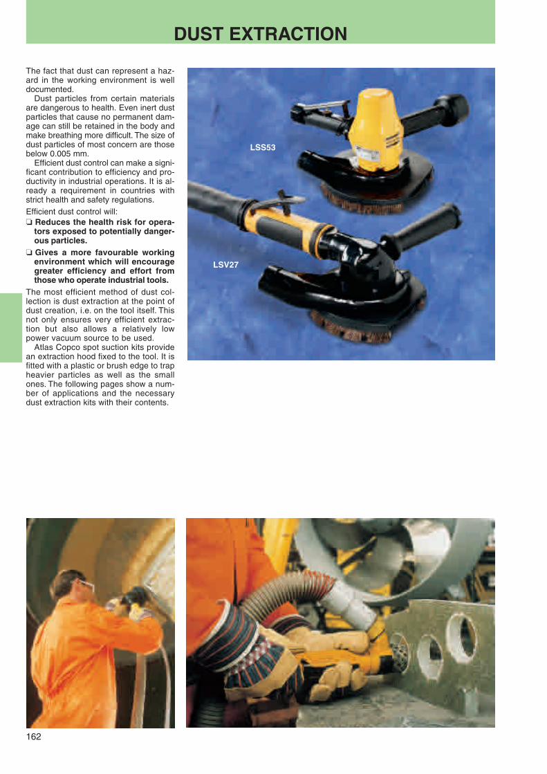
162
LSV27
LSS53
DUST EXTRACTION
The fact that dust can represent a haz-ard in the working environment is welldocumented.
Dust particles from certain materialsare dangerous to health. Even inert dustparticles that cause no permanent dam-age can still be retained in the body andmake breathing more difficult. The size ofdust particles of most concern are thosebelow 0.005 mm.
Efficient dust control can make a signi-ficant contribution to efficiency and pro-ductivity in industrial operations. It is al-ready a requirement in countries withstrict health and safety regulations.Efficient dust control will:❏ Reduces the health risk for opera-
tors exposed to potentially danger-ous particles.
❏ Gives a more favourable workingenvironment which will encouragegreater efficiency and effort fromthose who operate industrial tools.
The most efficient method of dust col-lection is dust extraction at the point ofdust creation, i.e. on the tool itself. Thisnot only ensures very efficient extrac-tion but also allows a relatively lowpower vacuum source to be used.
Atlas Copco spot suction kits providean extraction hood fixed to the tool. It isfitted with a plastic or brush edge to trapheavier particles as well as the smallones. The following pages show a num-ber of applications and the necessarydust extraction kits with their contents.

163
1
1a
2
4 5
3
1
2
4
5
3
6
7
ACCESSORIES
Spot suction accessories for die grindersSuction requirement: 125 m3/h (LSF17), 200 m3/h (LSF27)
Ordering No.LSF17 S 1 Chamber for burr 3780 3015 20
Optional 2 Diamond burr 6 mm 3780 5013 70
LSF17 S KIT FOR DRUM 3780 4011 60Includes 1 Chamber 3780 3015 20
3 Shaft dia 6 mm 3780 5090 304 Locking screw 3780 5090 60
Optional 5 Diamond drum 27 mm 3780 5033 00
LSF17 S E 1 Chamber for burr 3780 4007 30
Hose kits including 1.8 m vacuum hose and air hoseLSF17, hose Ø 25 mm 3780 2724 20LSF27, hose Ø 32 mm 3780 2724 30
Collets6 mm 4150 0075 008 mm 4150 0074 00
LSF27 S KIT FOR BURR 3780 4007 41
Includes 1 Chamber 3780 3300 511a Nozzle 3780 2730 10
Optional 2 Diamond burr 8 mm 3780 5014 20
LSF27 S KIT FOR DRUM 3780 4011 71Includes 1 Chamber 3780 3300 51
3 Shaft 8 mm 3780 5091 00Distance nut 3780 5091 50
4 Locking nut 3780 5092 00Hook wrench 3780 5092 50
Optional 5 Diamond drum, Ø 50 mm 3780 5035 00
DIE GRINDERS
ROUGH GRINDERS FORDEPRESSED CENTRE ANDCUT OFF WHEEL
Spot suction accessories for depressed centre and cut off wheelsSuction requirement: 250 m3/h
Ordering No.LSV27 ST12 125 mm wheel KIT 3780 4008 70
Includes 1 Chamber 3780 3101 102 Wheel guard 125 mm 3780 2726 433 Suction cap 125 mm 3780 2500 204 Distance washer 4150 1364 005 Adaptor UNF 3/8" UNC 5/8" 4021 0457 006 Nut UNC 5/8" 3780 2722 00
LSV37 ST/SA12-125 125 mm wheel KIT 3780 4008 72Includes 1 Chamber 3780 3101 11
2 Wheel guard 125 mm 3780 2726 433 Suction cap 125 mm 3780 2500 204 Distance washer (t =12.5 mm) 3780 2727 206 Nut M14 3780 2726 90
Optional Adapter 4150 1662 91
LSV50 S085 18 180 mm wheel KIT 3780 4021 50Includes 1 Chamber 3780 3133 10
2 Wheel guard 180 mm 3780 2726 503 Suction cap 180 mm 3780 2500 10
LSS53 S085 18 180 mm wheel KIT 3780 4011 10Includes 1 Chamber 3780 3101 00
2 Wheel guard 180 mm 3780 2726 503 Suction cap 180 mm 3780 2500 107 Flange EN 68 4170 0758 006 Nut 5/8" 3780 2722 00
Hose kits including 1.8 m vacuum hose Ø 38 mm and air hose Ø 13 mm (Ø 10 mm for LSV27)LSV27 3780 2724 40LSV37 3780 2724 41LSV50 3780 2724 41LSS53 3780 2724 41

164
1
72
46 3
5
SANDERS FOR FIBRE DISC Spot suction accessories for sanding with fibre disc. Sanders with UNC 5/8"spindle.Suction requirement: 250 m3/h
Ordering No.LSV27 S040/S060/S085 125 mm fibre disc KIT 3780 4007 80
Includes 1 Chamber 3780 3100 402 Suction cap 125 mm with brush 3780 2650 203 Backing pad 125 mm 3780 2710 304 Distance washer 12 mm 3780 2721 605 Nut 5/8" 3780 2722 00
LSV27 ST12-13 125 mm fibre disc KIT 3780 4008 60Includes 1 Chamber 3780 3101 10
2 Suction cap 125 mm with brush 3780 2650 203 Backing pad 125 mm 3780 2710 306 Distance washer 9 mm 3780 2721 507 Adaptor UNF 3/8" UNC 5/8" 4021 0457 005 Nut 5/8" 3780 2722 00
LSV27 S040/S060 180 mm fibre disc KIT 3780 4007 90Includes 1 Chamber 3780 3100 40
2 Suction cap 180 mm with brush 3780 2675 003 Backing pad 180 mm 3780 2710 606 Distance washer 9 mm 3780 2721 505 Nut 5/8" 3780 2726 70
LSV27 S021 180 mm fibre disc KIT 3780 4031 60Includes 1 Chamber 3780 6101 50
2 Suction cap 180 mm with brush 3780 2675 003 Backing pad 3780 2710 606 Distance washer 9 mm 3780 2721 605 Nut 5/8" 3780 2726 70
LSV37 S085/S066 125 mm fibre disc KIT 3780 4008 80Includes 1 Chamber 3780 3101 10
2 Suction cap 125 mm with brush 3780 2650 203 Backing pad 3780 2710 304 Distance washer 12 mm 3780 2721 605 Nut 5/8" 3780 2722 00
Optional Adapter 4150 1662 90
LSV37 S085/S066 180 mm fibre disc KIT 3780 4008 81Includes 1 Chamber 3780 3101 10
2 Suction cap 180 mm with brush 3780 2675 003 Backing pad 3780 2710 604 Distance washer 12 mm 3780 2721 605 Nut 5/8" 3780 2722 006 Distance washer 3 mm 3780 2721 30
Optional Adapter 4150 1662 90
LSV41 S025/S042 180 mm fibre disc KIT 3780 4018 20Includes 1 Chamber 3780 3132 80
2 Suction cap 180 mm with brush 3780 2675 003 Backing pad 180 mm 3780 2710 606 Distance washer 9 mm 3780 2721 505 Nut 5/8" 3780 2726 70Exhaust guard 4150 0938 80Silencer 4150 1005 80
LSS53 S060 180 mm fibre disc KIT 3780 4011 00Includes 1 Chamber 3780 3101 00
2 Suction cap 180 mm with brush 3780 2675 003 Backing pad 180 mm 3780 2710 604 Distance washer 12 mm 3780 2721 605 Nut 5/8" 3780 2726 70
GTG40 S060 180 mm fibre disc KIT 3780 4090 10Includes 1 Chamber 3780 3180 10
2 Suction cap 180 mm with brush 3780 2675 303 Backing pad 180 mm 3780 2710 304 Distance washer 3 mm 3780 2721 305 Flange nut 5/8" 3780 2722 00
Hose kits including 1.8 m vacuum hose,Ø 38 mm and air hose Ø 13 mm LSV27 3780 2724 40(Ø 10 mm for LSV27) LSV37/41, LSS53, GTG21/40 3780 2724 41
Brush for suction capSeparate brush for cap Ø 125 mm 3780 2678 00Separate brush for cap Ø 180 mm 3780 2677 50Separate brush (30 mm high) for cap Ø 180 mm 3780 2677 30
ACCESSORIES
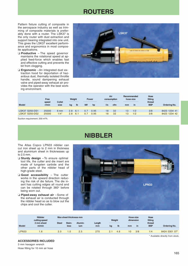
165
LSK37
LPN33
ROUTERS
Pattern fixture cutting of composite inthe aerospace industry as well as trim-ming of composite materials is prefer-ably done with a router. The LSK37 isthe only router with dust extraction andsupport bearing integrated into one unit.This gives the LSK37 excellent perform-ance and ergonomics in most compos-ite applications.❏ Productive – The speed governor
maintains the rotational speed at ap-plied feed-force which enables fastand effective cutting and prevents thebit from clogging.
❏ Ergonomic – An integrated dust ex-traction hood for deportation of haz-ardous dust, thermally isolated throttlehandle, sound dampening exhaustvalve and piped-away exhaust air pro-vides the operator with the best work-ing environment.
Air Recommended HoseFree Weight Power consumption hose size fitting
speed Collet threadModel r/min size kg lb kW hp l/s cfm mm in BSP Ordering No.
LSK37 S250-DS1 25000 6 mm 2.8 6.1 0.7 0.95 18 32 13 1/2 3/8 8423 1234 41LSK37 S250-DS2 25000 1/4" 2.8 6.1 0.7 0.95 18 32 13 1/2 3/8 8423 1234 42
NIBBLERThe Atlas Copco LPN33 nibbler cancut iron sheet up to 2 mm in thicknessand aluminium sheet in thicknesses upto 2.5 mm.❏ Sturdy design – To ensure optimal
tool life, the cutter and die insert aremade of tungsten carbide and theother parts of the nibbler head ofhigh-grade steel.
❏ Good accessibility – The cutterworks in the upward direction reduc-ing the risk of die failure. The die in-sert has cutting edges all round andcan be rotated through 360o beforebeing worn out.
❏ Piped-away exhaust air – Some ofthe exhaust air is conducted throughthe nibbler head so as to blow out thechips and cool the cutter.
Nibbler Max sheet thickness mm Hose size Hosecutting speed Weight dimension fitting2 mm sheet Steel Stain- Alumin- Length thread
Model m/min less ium mm kg lb mm in BSP Ordering No.
LPN33 1.6 2.0 1.0 2.5 270 2.1 4.6 10 3/8 1/4 8424 0301 07*
* Available directly from stock.
ACCESSORIES INCLUDED3 mm hexagon wrench
Hose fitting for 10 mm air hose
Suction requirement: 200 m3/h.

166
LCS37
LCS10
CIRCULAR CUTTERS
Cutting operations in glass and carbonfibre as well as metal sheet, wood andsteel can successfully be performedwith a circular cutter.❏ Effective – LCS10 and -37 cut to a
depth of 10 and 26 mm respectively.❏ LCS37 is suitable for diamond coated
blades only.❏ Dust extraction – Cutting of compos-
ite materials generates dust contain-ing particles hazardous to health. Thedust must be deported in order to pre-vent the operator from inhaling them.
LCS37 is equipped with a cutter bladeguard with integrated dust extractionhood for external vacuum source.
OPTIONAL ACCESSORIESSuction hose set, L=1.8 m, Dia 32 mm (1 1/4")
Designation Ordering No.
LCS37 3780 2724 31
MaxMax cutter Air con- Hose
Free Max cutting blade Weight Hose sumption fittingspeed outut depth dia size thread
Model r/min kW mm mm kg lb mm l/s cfm BSP Ordering No.
Circular cuttersLCS10 3000 0.3 10 50 1.4 3.1 6.3 7.6 16 1/4 8424 1161 38*LCS37 S150Da 15000 1.0 26 100 1.6 3.5 13.0 23.0 48.7 3/8 8424 1125 05*
ACCESSORIES INCLUDEDLCS10Cutter blade, 62 teeth
Hexagon wrench
Hose nipple for 6.3 mm air hose
LCS37Flanges for diamond blade
Hose nipple for 13 mm air hose
a Suction requirement: 200 m3/h.b 1.1 kW with oil.
OPTIONAL ACCESSORIES. Cutter blades
* Available directly from stock.
Maxthickness No. of
of material teeth Dia HoleModel Application mm mm mm mm Ordering No.
LCS10 Steel sheet 1.0 92 50 10 4190 0394 00Steel sheet 1.0 62 50 10 4190 0395 00 (std)Aluminium 2.5 34 50 10 4190 0396 00Wood 10.0 34 50 10 4190 0396 00
LCS37 Glassfibre 25.0 44/60 (Grain) 75 12 3780 5073 00Glassfibre 25.0 44/60 (Grain) 100 12 3780 5074 00

Percussivetools
Choose Atlas Copco andyou’ve cracked it!
Chipping hammers, riveting hammers, rammers,scalers and bucking bars – our percussive tools makelight of the toughest jobs. The vibration-damped Ergo-line range includes sophisticated ergonomic featuresdesigned to minimize operator fatigue.
Contents PageRules for safer operation .............................. 168
Chipping hammers – vibration-dampedand silenced ................................................ 169
Chipping hammers ....................................... 170
Scaler – vibration-controlled ........................ 171
Chipping hammers/scalers ........................... 172
Needle scaler ............................................... 173
Rust and weld scalers .................................. 174
Riveting system ........................................... 175
Riveting hammers – vibration-damped ......... 176
Bucking bars – vibration-damped ................. 178
Riveting hammers – conventional type ........ 180
Chisels ......................................................... 181
Rammers ..................................................... 184

168
RULES FOR SAFER OPERATIONIMPORTANT: All local safety regulations with respect to installation, operation and overhaul must always be followed.
AVOID ACCIDENTS
The chisel, die or punch may fall out or may be shot outof the tool accidentally causing serious injury.
AND
❏ Be aware that the chisel maybreak during operation.
❏ Never trigger a hammer unlessheld against a work piece.
❏ Remove chisel, die or punchfrom tool when work is over.
❏ When finishing a job, discon-nect the tool from its air supply.
❏ Before changing accessories,chisel or die – disconnect thetool from the air supply.
Chips and sparks shall be prevented from striking aneye or another worker.
To prevent vision loss:❏ Always wear eye protection.❏ Isolate work of this kind by
using barriers between workstations.
❏ Do not use the tool for otherpurposes than it is intendedfor.
Gloves protect fingers from pinching, scuffing andscraping.
❏ Protectives shoes may prevent your feet from being injured.
Explosive atmosphere must not be ignited.
To prevent injury and propertyloss from fires:❏ Use other technique.❏ Use accessories of non spark-
ing material (e.g. needle at-tachment of Beryllium copperfor a needle scaler).
Electric shock may be fatal.❏ Avoid chiseling into electric wiring hidden inside walls etc.
LONG TERM RISKS
Always use ear protection.
Vibration may be harmful to hands and arms.
Dust generated during operation may be harmful.❏ Use spot suction or a breathing
apparatus.
PROPER USE AND MAINTENANCE
Do not perform idle blows with a hammer.
❏ They will cause high internalstresses and shorten the life ofthe tool.
❏ Note the risk of shooting out thechisel, die or punch if the retain-er is not in order or damaged.
Quick coupling.
Follow the tool manual and the lubrication instructions.
Make overhaul at regular intervals.
1
2
3
4
5
6
7
8
9
10
11
12
❏ Use vibration dampened toolsif available.
❏ Reduce the total time of expo-sure to vibrations, particularly ifthe operator has to guide thechisel by hand.
To prevent gradual loss of hear-ing due to exposure to high noiselevel – wear ear protection.
To prevent injury from a flyingchisel:❏ Always use a retainer.❏ Inspect the retainer for wear or
damage regularly.
❏ If a coupling is used on a per-cussive tool, it shall be sepa-rated from the tool by a whiphose (length 0.5 m).

169
RRD57
RRF21
RRF31
RRF21/31
RRD37/57
* Available directly from stock.
Retainer, open type
Model Ordering No.
RRF21 3512 0290 90
RRF31 3512 0305 90
Equipment forspot suction Ordering No.
Suction cap 3510 0477 80
Hose cap 3510 0536 00
Suction hose Ø 40 mm,length 15 m 3780 1602 02
RRD37, RRD57The RRD37 and RRD57 can be equipped withspot suction.
CHIPPING HAMMERSVibration-damped and silenced
Tough on the job – easy on youChoose the tools that give the best re-sults in the toughest working conditions,yet are easy on the operator. These areeffective, reliable tools for fettling ofcastings, chipping operations in the me-chanical industry, hole making and lightdemolition of concrete.❏ RRF21/31 have a sturdy D-handle in
light metal alloy for a high power-to-weight ratio and steady grip. The com-pact, vibration-controlled (2.5 m/s2)design offers good accessibility andease of use.
❏ RRD37/57 are light, quiet and havea long service life. They have lightalloy tool casings, very low vibration(below 2.5 m/s2) and noise levels,vibration damping in both hand grips,and piped away exhaust.
ACCESSORIES INCLUDEDRRF models Chisel retainer and a hose fittingRRD models Flat chisel
Silencer completeHand gripKey
DIMENSIONS (mm)
OPTIONAL ACCESSORIESA selection of chiselsRRF21/31 ISO 12.7 mmRRD37/57 ISO with splines
For a wide choice of chisels, see page 181.
Power regulator
Model Ordering No.
RRF21 and -31 3512 0273 80
a Effective piston dia 19 mm, 0.75 in.b Effective piston dia 21.5 mm, 0.85 in.c ISO.d Spline.e Integrated hose barb.
Energy AirPiston dia Stroke per blow Weight Bushing consumption Hose size
Blows Length Air inletModel Hz mm in mm in J ft lb mm kg lb mm in l/s cfm mm in BSP Ordering No.
Chipping hammers vibration dampedRRF21-01 57 18 0.7 33 1.3 2.0 1.5 245 1.75 3.3 12.7c 0.50 6.5 13.8 10.0 3/8 3/8 8425 1104 05*RRF31-01 38 22 0.9 43 1.7 4.4 3.2 265 2.5 5.3 12.7c 0.50 7.5 15.9 10.0 3/8 3/8 8425 1104 15*RRD37-11 35 27/19a 1.1/0.8 70 2.8 6.8 5.0 418 3.0 6.6 17.3d 0.68 7.2 15.3 12.5 1/2 speciale 8425 1101 22*RRD37-12 35 27/19a 1.1/0.8 70 2.8 6.8 5.0 418 3.0 6.6 17.3d 0.68 7.2 15.3 12.5 1/2 speciale 8425 1101 30*RRD57-11 31 28/18b 1.1/0.8 92 3.6 9.3 6.9 458 3.4 7.5 17.3d 0.68 9.5 20.1 12.5 1/2 speciale 8425 1103 20*RRD57-12 31 28/18b 1.1/0.8 92 3.6 9.3 6.9 458 3.4 7.5 17.3d 0.68 9.5 20.1 12.5 1/2 speciale 8425 1103 38*
Model L H D
RRF21 245 160 33RRF31 265 170 36RRD37 418 175 –RRD57 458 190 –
-01 and -11: Guided models,-02 and -12: Non guided models.

170
∅∅DD
∅
L
H
RRC75B
RRC34B
RRC22F
CHIPPING HAMMERS
Atlas Copco chipping hammers of typeRRC are used mainly in foundries, inheavy industry and for hole-making andlight demolition in the building industry.❏ Dependable – Their robust construc-
tion makes them highly dependable.❏ Efficient – RRC65 and RRC75 have
a blow rate which makes them par-ticularly suitable for roughening.
❏ Chisel retainer – for safer jobs –RRC22-RRC75 are delivered with achisel retainer as standard. For thesame reason, choose a tool that youcan guide via the machine itself andnot by holding the chisel.
As standard, Atlas Copco chippinghammers of series RRC are deliveredwith a standard, guided ISO hexagonnozzle (-01) or a round, non guidedshank nozzle (-02).
OPTIONAL ACCESSORIESA selection of chisels fitting -01, -02 type,see page 181.
ACCESSORIES INCLUDEDRRC22FRRC34B Chisel retainer andRRC65B hose fittingRRC75B
Energy AirPiston dia Stroke per blow Weight Bushing consumption Hose size
Blows Length Air inletModel Hz mm in mm in J ft lb mm kg lb mm in l/s cfm mm in BSP Ordering No.
Chipping hammers including chisel retainerRRC22F-01 62 15 0.6 52 2.0 2.7 2.0 260 2.2 4.9 12.7a 0.50 6.2 13.1 10 3/8 3/8 8425 0202 22*RRC22F-02 62 15 0.6 52 2.0 2.7 2.0 260 2.2 4.9 12.7a 0.50 6.2 13.1 10 3/8 3/8 8425 0202 30RRC34B-01 45 24 0.9 67 2.6 5.5 4.1 330 4.5 9.9 17.3a 0.68 8.0 14.0 12.5 1/2 specialb 8425 0212 53*RRC34B-02 45 24 0.9 67 2.6 5.5 4.1 330 4.5 9.9 17.3a 0.68 8.0 17.0 12.5 1/2 specialb 8425 0212 61RRC65B-01 40 29 1.1 50 2.0 10.0 7.3 335 5.9 13.0 17.3a 0.68 10.8 22.9 12.5 1/2 specialb 8425 0225 33*RRC65B-02 40 29 1.1 50 2.0 10.0 7.3 335 5.9 13.0 17.3a 0.68 10.8 22.9 12.5 1/2 specialb 8425 0225 41*RRC75B-01 30 29 1.1 75 3.0 16.0 11.8 390 6.5 14.3 17.3a 0.68 14.0 29.6 12.5 1/2 specialb 8425 0225 58*RRC75B-02 30 29 1.1 75 3.0 16.0 11.8 390 6.5 14.3 17.3a 0.68 14.0 29.6 12.5 1/2 specialb 8425 0225 66*
* Available directly from stock.a ISO.b Integrated hose barb.
DIMENSIONS (mm)Model L H D
RRC22 260 155 34RRC34 330 160 43RRC65 335 170 54RRC75 390 170 54
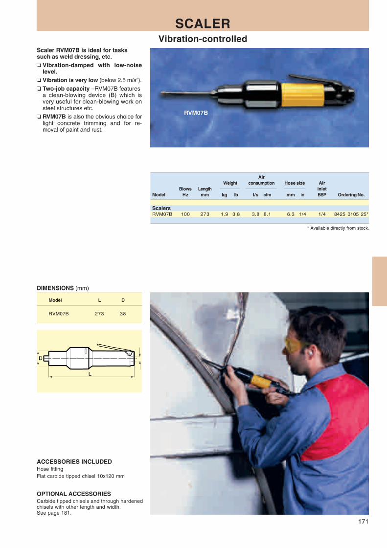
171
D
L
RVM07B
SCALERVibration-controlled
Scaler RVM07B is ideal for taskssuch as weld dressing, etc.❏ Vibration-damped with low-noise
level.❏ Vibration is very low (below 2.5 m/s2).❏ Two-job capacity – RVM07B features
a clean-blowing device (B) which isvery useful for clean-blowing work onsteel structures etc.
❏ RVM07B is also the obvious choice forlight concrete trimming and for re-moval of paint and rust.
ACCESSORIES INCLUDEDHose fittingFlat carbide tipped chisel 10x120 mm
OPTIONAL ACCESSORIESCarbide tipped chisels and through hardenedchisels with other length and width.See page 181.
* Available directly from stock.
AirWeight consumption Hose size Air
Blows Length inletModel Hz mm kg lb l/s cfm mm in BSP Ordering No.
ScalersRVM07B 100 273 1.9 3.8 3.8 8.1 6.3 1/4 1/4 8425 0105 25*
DIMENSIONS (mm)
Model L D
RVM07B 273 38

172
L
DH
1 2D
RRC13B
CHIPPING HAMMERS / SCALERS
Choose between two different modelsfor heavy slag chipping and for instanttrimming of concrete.❏ High removal rate – RRC13 is very
effective and has a high removal ratein relation to its low weight.
❏ Well proven percussive mechanismand retainer.
❏ Two-job capacity – RRC13B withextra clean-blowing device.
❏ Improved back head – Throttle valveand lever with really Heavy Duty per-formance for long service life. Cleanblowing system with twice the previ-ous blow capacity. Big blow button foreasy operation and sturdy valve stemto resist rough handling.
Energy AirPiston dia Stroke per blow Weight consumption Hose size
Blows Length Air inletModel Hz mm in mm in J ft lb mm kg lb l/s cfm mm in BSP Ordering No.
ScalersRRC13 73 15 0.6 35 1.4 1.4 1.0 221 1.4 3.1 4.0 8.0 10 3/8 3/8 8425 0101 30*RRC13B 73 15 0.6 35 1.4 1.4 1.0 231 1.6 3.5 4.0 8.0 10 3/8 3/8 8425 0101 33*
* Available directly from stock.
OPTIONAL ACCESSORIESACCESSORIES INCLUDEDHose fittingScaling chisel
DIMENSIONS (mm)
Model L H D1 D2
RRC13 221 65 45 41.5RRC13B 231 65 45 41.5
RRC13 / RRC13B Ordering No.
Hand guard 3510 0246 90
All steel retainer 3510 0245 80
Silencer 3510 0366 80
Chisels for RRC13 and -13B:Square shank 13.0 mm.
For a wide choice of chisels,see page 181.
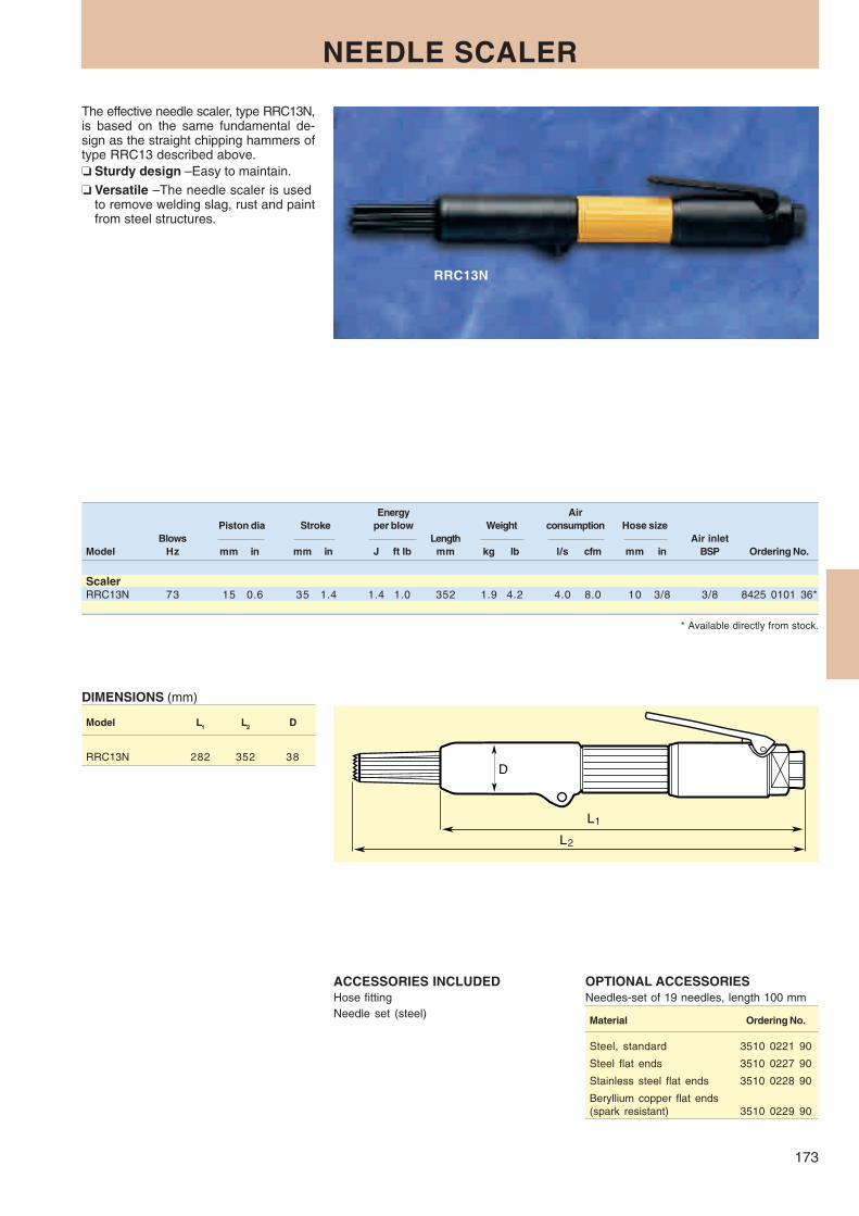
173
RRC13N
L
L
1
2
D
NEEDLE SCALER
The effective needle scaler, type RRC13N,is based on the same fundamental de-sign as the straight chipping hammers oftype RRC13 described above.❏ Sturdy design – Easy to maintain.❏ Versatile – The needle scaler is used
to remove welding slag, rust and paintfrom steel structures.
Energy AirPiston dia Stroke per blow Weight consumption Hose size
Blows Length Air inletModel Hz mm in mm in J ft lb mm kg lb l/s cfm mm in BSP Ordering No.
ScalerRRC13N 73 15 0.6 35 1.4 1.4 1.0 352 1.9 4.2 4.0 8.0 10 3/8 3/8 8425 0101 36*
* Available directly from stock.
OPTIONAL ACCESSORIESNeedles-set of 19 needles, length 100 mm
Material Ordering No.
Steel, standard 3510 0221 90
Steel flat ends 3510 0227 90
Stainless steel flat ends 3510 0228 90
Beryllium copper flat ends(spark resistant) 3510 0229 90
ACCESSORIES INCLUDEDHose fittingNeedle set (steel)
DIMENSIONS (mm)
Model L1 L2 D
RRC13N 282 352 38

174
RP3
RP1
H
L
C
RUST AND WELD SCALERS
The RP rust and weld scaler is designedfor removal of rust, paint and other coatingfrom steel structures, steam boilers etc.❏ Easy to maintain – The 4-point bit,
with cemented carbide insert, is re-placeable.
❏ Two models for flexible work – Therust and weld scaler is available inversions with 1 impact head (RP1)and with 3 impact pistons (RP3).
AirWeight consumption Hose size
Blows Length Air inletModel Hz mm kg lb l/s cfm mm in BSP Ordering No.
ScalersRP1 69 485 2.0 4.4 3.2 6.8 10 3/8 3/8 8425 0301 06*RP3 69 515 3.9 8.6 9.6 20.3 10 3/8 3/8 8425 0301 14*
ACCESSORIES INCLUDEDHose fittingFour-point carbide bit, length 55 mm
* Available directly from stock.
OPTIONAL ACCESSORIES
RP1 and RP3 Ordering No.
Vibration-damped supporthandle 3550 0079 80
DIMENSIONS (mm)
Model L H C
RP1 485 80 –RP3 515 80 180

175
RIVETING SYSTEMS
The Atlas Copco riveting system includes vibration-dampedhammers RRH and bucking bars RBB – as well as conven-tional riveting hammer RRN.
The vibration-damped riveting hammers – RRH – areavailable in different sizes, RRH04P, RRH06P, RRH08P,RRH10P and RRH12P.
Each size is available in “Trigger start” and '“Push to start”models.
The conventional riveting hammer – RRN – is available inone size: RRN11P.
The number of blows and the power are critical factorswhich determine the strength of a riveted joint. A few powerful
blows are needed to fill out the hole and form a head whenupsetting the rivet. The impact force is critical to some extentwhen working with aluminium alloys, as too many blows canembrittle the metal.
In terms of capacity, the tools overlap. The table on page177 helps you to find the right tool for your particular applica-tion of riveting.
The vibration-damped bucking bars RBB are available intwo versions – the simple spring damped – SP type and theair servo assisted SA type. There are three sizes RBB04,RBB10 and RBB16.
How to find a suitable hammer and bucking bar
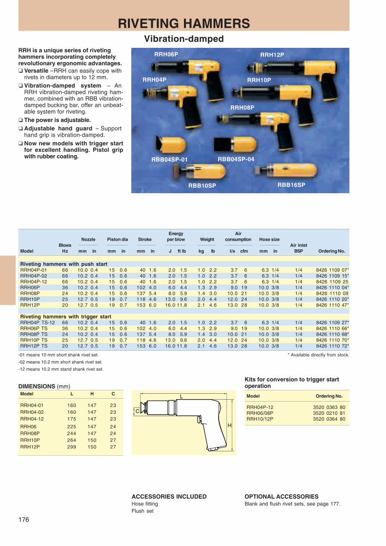
176
L
C
H
RRH06P
RRH10P
RBB04SP-01 RBB04SP-04
RBB16SP
RRH08P
RRH12P
RRH04P
RBB10SP
RIVETING HAMMERSVibration-damped
RRH is a unique series of rivetinghammers incorporating completelyrevolutionary ergonomic advantages.❏ Versatile – RRH can easily cope with
rivets in diameters up to 12 mm.❏ Vibration-damped system – An
RRH vibration-damped riveting ham-mer, combined with an RBB vibration-damped bucking bar, offer an unbeat-able system for riveting.
❏ The power is adjustable.❏ Adjustable hand guard – Support
hand grip is vibration-damped.❏ Now new models with trigger start
for excellent handling. Pistol gripwith rubber coating.
-01 means 10 mm short shank rivet set.
-02 means 10.2 mm short shank rivet set.
-12 means 10.2 mm stand shank rivet set.
* Available directly from stock.
DIMENSIONS (mm)Model L H C
RRH04-01 160 147 23RRH04-02 160 147 23RRH04-12 175 147 23
RRH06 225 147 24RRH08P 244 147 24RRH10P 264 150 27RRH12P 299 150 27
Energy AirNozzle Piston dia Stroke per blow Weight consumption Hose size
Blows Air inletModel Hz mm in mm in mm in J ft lb kg lb l/s cfm mm in BSP Ordering No.
Riveting hammers with push startRRH04P-01 66 10.0 0.4 15 0.6 40 1.6 2.0 1.5 1.0 2.2 3.7 6 6.3 1/4 1/4 8426 1109 07*RRH04P-02 66 10.2 0.4 15 0.6 40 1.6 2.0 1.5 1.0 2.2 3.7 6 6.3 1/4 1/4 8426 1109 15*RRH04P-12 66 10.2 0.4 15 0.6 40 1.6 2.0 1.5 1.0 2.2 3.7 6 6.3 1/4 1/4 8426 1109 25RRH06P 36 10.2 0.4 15 0.6 102 4.0 6.0 4.4 1.3 2.9 9.0 19 10.0 3/8 1/4 8426 1110 04*RRH08P 24 10.2 0.4 15 0.6 137 5.4 8.0 5.9 1.4 3.0 10.0 21 10.0 3/8 1/4 8426 1110 09RRH10P 25 12.7 0.5 19 0.7 118 4.6 13.0 9.6 2.0 4.4 12.0 24 10.0 3/8 1/4 8426 1110 20*RRH12P 20 12.7 0.5 19 0.7 153 6.0 16.0 11.8 2.1 4.6 13.0 28 10.0 3/8 1/4 8426 1110 47*
Riveting hammers with trigger startRRH04P TS-12 66 10.2 0.4 15 0.6 40 1.6 2.0 1.5 1.0 2.2 3.7 6 6.3 1/4 1/4 8426 1109 27*RRH06P TS 36 10.2 0.4 15 0.6 102 4.0 6.0 4.4 1.3 2.9 9.0 19 10.0 3/8 1/4 8426 1110 66*RRH08P TS 24 10.2 0.4 15 0.6 137 5.4 8.0 5.9 1.4 3.0 10.0 21 10.0 3/8 1/4 8426 1110 68*RRH10P TS 25 12.7 0.5 19 0.7 118 4.6 13.0 9.6 2.0 4.4 12.0 24 10.0 3/8 1/4 8426 1110 70*RRH12P TS 20 12.7 0.5 19 0.7 153 6.0 16.0 11.8 2.1 4.6 13.0 28 10.0 3/8 1/4 8426 1110 72*
OPTIONAL ACCESSORIESBlank and flush rivet sets, see page 177.
ACCESSORIES INCLUDEDHose fittingFlush set
Kits for conversion to trigger startoperation
Model Ordering No.
RRH04P-12 3520 0363 80RRH06/08P 3520 0210 81RRH10/12P 3520 0364 80

177
28
∅12.7R19
29.5
∅10.2ISO
R13
17.5
∅10.2
R1.5
17.5
∅10.0
R1.5
Ø13
175
Nominal Max. Rivet Diameter Capacity
Dural Steel Titanium
Hammer modela mm in mm in mm in Bucking bar model requiredb
RRH04 2- 5 3/32 - 3/16 1- 4 3/21 - 5/32 RBB04 RBB10
RRN11 2- 5 3/32 - 3/16 1- 4 3/32 - 5/32
RRH06 4- 7 5/32 - 1/4 3- 6 1/8 - 1/4 2- 4 3/32 - 5/32 RBB10 RBB16
RRH08 5- 8 3/16 - 5/16 4- 7 5/32 - 1/4 3- 6 1/8 - 1/4 RBB10 RBB16
RRH10 5- 9 3/16 - 3/8 6- 8 1/4 - 5/16 4- 7 5/32 - 1/4 RBB16
RRH12 8-11 7-10 1/4 - 3/8 6- 9 1/4 - 1/8 RBB16
SELECTION GUIDE
RIVET SETS. RRH and RRN
Shank Flush set Blank rivet setHammer type Model mm Ordering No. Ordering No.
RRH04P-01 (–01) 10.0 spec 3085 0347 00 3006 0983 00RRN11P-01
RRH04P-02 (–02) 10.2 spec 3085 0352 00 3085 0353 00RRN11P-02
RRH04P-12 (–12) 10.2 std 3085 0324 00 3085 0022 00RRH06P 10.2 stdRRH08P 10.2 stdRRN18P 10.2 stdRRN24P 10.2 std
RRH10P/s 12.7 std 3085 0323 00 3085 0021 00RRH12P 12.7 stdRRN34P 12.7 std
Mandrel blankRRH04P-12 10.2 std 3085 0212 00RRH06PRRH08P
a Hammer capacity depends on direct/indirect riveting as well as Panel density and stiffness.b Bucking bar capacity is dependent on dolly weight.

178
RBB04 SP-01 – SP-02 – SP-03 – SP-04 – SP-05Ø 60 43
30
26
46
60
40
40
40
40
Ø 46
88
126
15o
RBB04SP-01
RBB16SP
RBB16SA
RBB04SP-04
RBB10SP
RBB10SA
C
H
L
BUCKING BARSVibration-damped
An efficient riveting system consists of vi-bration-damped bucking bars togetherwith vibration-damped riveting hammers.❏ Self-adjustable – RBB10SA and
RBB16SA feature a self-adjustingdamping system which requires acompressed air supply. RBB04SP,RBB10SP and RBB16SP use a springas damping element and conse-quently do not require an air supply.
❏ Flexible – The bucking bars can befitted with several different inter-changeable dolly configurations via aquick change retainer for maximumflexibility.
❏ Cramped spaces – Mini buckingbars RBB04SP are ideal for work inconfined spaces. The large masstypes -04, -05 will in most applicationsset the rivet faster than the smallermodels.
Weight Diameter Air consumption
Model kg lb mm in l/s cfm Ordering No.
Bucking bars with standard dollya
RBB10SA 1.3 2.9 48 2.0 0.5 1.1 8426 9101 77RBB10SP 1.1 2.4 48 2.0 – – 8426 9101 74RBB16SA 1.9 4.2 48 2.0 0.5 1.1 8426 9101 78RBB16SP 1.7 3.7 48 2.0 – – 8426 9101 76
Bucking bars without dolly and rodRBB10SA-U 1.0 2.2 48 2.0 0.5 1.1 8426 9101 73RBB10SP-U 0.9 2.0 48 2.0 – 1.1 8426 9101 86RBB16SA-U 1.7 3.7 48 2.0 0.5 1.1 8426 9101 75RBB16SP-U 1.5 3.3 48 2.0 – – 8426 9101 94
Mini bucking barsRBB04SP-01 0.8 1.8 46 1.8 – – 8426 9101 10*RBB04SP-02 0.8 1.8 46 1.8 – – 8426 9101 11RBB04SP-03 0.8 1.8 46 1.8 – – 8426 9101 12RBB04SP-04 1.3 2.9 46 1.8 – – 8426 9101 13*RBB04SP-05 1.4 3.1 46 1.8 – – 8426 9101 14
a Standard dolly assy (3085 0335 93). * Available directly from stock.
ACCESSORIES INCLUDEDAll SA-models Hose and hose fittingAll 10/16 models Plastic cover
DIMENSIONS (mm)Model L H C
RBB10SA/SP 165 49 140RBB16SA/SP 200 49 198
Dollies other than standard, see page 179.
OPTIONAL ACCESSORIESDesignation Ordering No.
Rod 5 mm 3085 0365 03Rod 50 mm 3085 0365 04Rod 100 mm 3085 0365 05
Swivel for SA models,complete kit incl hose 3520 0312 80
Plastic cover forRBB10SA 3520 0317 00RBB10SP 3520 0315 00RBB16SA 3520 0318 00RBB16SP 3520 0316 00
Dollies other than standard, see page 179.
Dimensions in mm

179
Ø16
.0 u
5
5 3085 0365 03
100 3085 0365 05
50 3085 0365 04
3015
2550
Ø16
.0 J
S7
20
25
25
25
3015
60
12.525
1020
25
1530
60
22.545
20
10
15
2040
20
1530
94
2040
20
13
50
50
15o
50
3015
65
12.525
35
40
15
3015
65
35
15
12
15
3046
2540
12.5
A
B
C
G
H
D
F J
E
DIMENSIONAL DRAWING of dollies available
Other than Atlas Copco’s dollies can also be used and press fitted onto a rod. Please see rod (i.e. hole) specification in thebelow drawing. Custom design dollies are recommended to be manufactured locally and fitted on to Atlas Copco rods.
Dollies for RBB10 and RBB16, all models
Weight Ordering No. Weight Ordering No. Weight Ordering No.With rod With rod With rod
Dolly type kg lb 5 mm kg lb 50 mm kg lb 100 mm
A 0.37 0.8 3085 0335 93a 0.47 1.0 3085 0335 94 0.67 1.5 3085 0335 95B 0.25 0.55 3085 0363 93 0.35 0.8 3085 0363 94 0.55 1.3 3085 0363 95C 0.36 0.8 3085 0364 93 0.46 1.0 3085 0364 94 0.66 1.5 3085 0364 95D 0.43 0.9 3085 0337 93 0.53 1.2 3085 0337 94 0.73 1.6 3085 0337 95
E 0.35 0.8 3085 0339 93 0.45 1.0 3085 0339 94 0.65 1.5 3085 0339 95F 0.57 1.3 3085 0336 93 0.67 1.5 3085 0336 94 0.87 1.9 3085 0336 95G 1.00 2.2 3085 0338 93 1.10 2.4 3085 0338 94 1.30 2.9 3085 0338 95H 0.62 1.4 3085 0340 93 0.72 1.6 3085 0340 94 0.92 2.0 3085 0340 95
J 0.62 1.4 3085 0341 93 0.72 1.6 3085 0341 94 0.92 2.0 3085 0341 95
a Standard dolly assy.
ACCESSORIES

180
L
H
C
RRN11
RIVETING HAMMERSConventional type
Energy AirNozzle Piston dia Stroke per blow Weight consumption Hose size
Blows Air inletModel Hz mm in mm in mm in J ft lb kg lb l/s cfm mm in BSP Ordering No.
Riveting hammersRRN11P-01 66 10.0 0.4 15 0.6 40 1.6 2.0 1.5 1.2 2.6 3.4 7.2 6.3 1/4 1/8 8426 1101 05*RRN11P-02 66 10.2 0.4 15 0.6 40 1.6 2.0 1.5 1.2 2.6 3.4 7.2 6.3 1/4 1/8 8426 1101 13*
ACCESSORIES INCLUDEDRRN11PHose fitting and retainer
OPTIONAL ACCESSORIESBlank and flush rivet sets, see page 177.
For riveting in confined spaces we re-commend our RRN11 riveting hammer.❏ RRN11 – is the smallest riveting
hammer available on the market, withunique accessibility.
❏ Adjustable – The RRN11 has a built-in adjustment knob with which youcan set the power for different rivetmaterials and sizes.
❏ Controllable – The trigger is easily op-erated and provides excellent control.
-01 means 10 mm short shank rivet set.-02 means 10.2 mm short shank rivet set.
* Available directly from stock.
DIMENSIONS (mm)
Model L H C
RRN11P 100 170 23

181
CHISELS
Chisels for Chipping Hammers. All chisels are normally through hardened. Otherwise, see tables.
Square shank 13.0 mm RRC13, RRC13B 1
Extended square shank ISO, 12.7 mm RRC15 1
Hexagon and round shank ISO, RRC22F-01, RRC22F-02 2round collar 12.7 mm RRF21, RRF31
Hexagon shank ISO RRC34B-01, RRC65B-01, 3round collar 17.3 mm RRC75B-01
Round shank ISO, RRD37, RRD57 3with splines 17.3 mm
Hexagon shank ISO RRC34-01, RRC65-01, 4without round collar 17.3 mm RRC75-01
Round shank ISO, RRC34-02, RRC65-02, 4without collar 17.3 mm RRC75-02
Special shank RVM07B 5
Figure Shank type Tools Table

182
A B
A B
A B
A B
Width Length Square ISO Extended square13 mm (1/2") 12.7 mm (1/2")
Chisel type Designation mm in mm in Ordering No. Ordering No.
Chisel blank 15 0.59 155 6.1 3085 0020 00 3085 0228 0215 0.59 200 7.9 3085 0020 0115 0.59 300 11.8 3085 0020 02
Flat chisel 15 0.59 165 6.1 3085 0227 00 3085 0230 0115 0.59 200 7.9 3085 0227 01
Wide flat chisel 35 1.38 165 6.5 3085 0032 00 3085 0232 0135 1.38 200 7.9 3085 0032 0135 1.38 300 11.8 3085 0032 0255 2.17 165 6.5 3085 0332 00
Angle scraper chisel 35 1.38 165 6.5 3085 0176 00 3085 0362 0035 1.38 200 7.9 3085 0176 0155 2.17 165 6.5 3085 0333 00
Scaling chisel 15 0.59 155 6.1 3085 0018 00 3085 0229 0115 0.59 200 7.9 3085 0018 0215 0.59 300 11.8 3085 0018 01
Width Length Hex ISO Round ISO12.7 mm (1/2") 12.7 mm (1/2")
Chisel type Designation mm in mm in Ordering No. Ordering No.
Chisel blank 13 0.51 200 7.9 3085 0182 0013 0.51 350 13.8 3085 0182 0113 0.51 400 15.7 3085 0182 0413 0.51 500 19.7 3085 0182 05
Flat chisel 13 0.51 200 7.9 3085 0183 00 3085 0184 0035 1.38 300 11.8 3085 0376 00
Sharp chisel 15 0.59 200 7.9 3085 0170 0015 0.59 300 11.8 3085 0170 01
Spot weld chisel 17 0.69 200 7.9 3085 0301 00
Angle scraper chisel 30 1.18 200 7.9 3085 0262 00
Pipe cutting chisel 20 0.78 200 7.9 3085 0302 0035 1.38 200 7.9 3085 0303 00
Plate cutting chisel 14.5 0.57 200 7.9 3085 0263 00
Plate cutting chisel 16 0.62 200 7.9 3085 0173 00
Moil point chisel 13 0.51 200 7.9 3085 0297 0013 0.51 305 12.0 3085 0297 01
2A.Chisels with hexagon shank ISO, round collar 12.7 mm 2B.Chisels with round shank ISO, round collar 12.7 mm
1A.Chisels with square shank 13.0 mm 1B.Chisels with square shank ISO 12.7 mm

183
A B
A B
A B
4A.Chisels with ISO shank without collar, round 4B.Chisels with ISO shank without collar, hexagon
Round HexagonWidth Length 17.3 mm (0.68") 17.3 mm (0.68")
ISO ISOChisel type Designation mm in mm in Ordering No. Ordering No.
Chisel blank 23 0.91 200 7.9 3085 0150 00 3085 0140 0023 0.91 560 22.0 3085 0140 01
Flat chisel 23 0.91 225 8.9 3085 0225 00 3085 0224 00
3A.Chisels with hexagon shank ISO, round collar 17.3 mm 3B.Chisels with round ISO shank with splines 17.3 mm
Round ISOWidth Length Hex ISO Width Length with splines
17.3 mm (0.68") 17.3 mm (0.68")Chisel type Designation mm in mm in Ordering No. mm in mm in Ordering No.
Chisel blank 22 0.86 335 13.1 3085 0220 00 22 0.86 250 9.8 3085 0242 00 22 0.86 560 22.0 3085 0220 01 22 0.86 340 13.4 3085 0242 01 22 0.86 1060 41.7 3085 0220 02 22 0.86 550 21.7 3085 0242 02
22 0.86 800 31.5 3085 0242 03 22 0.86 1200 47.2 3085 0242 04
Flat chisel 22 0.86 200 10.2 3085 0221 00 22 0.86 215 8.5 3085 0236 00 22 0.86 335 13.1 3085 0221 01 22 0.86 250 9.8 3085 0236 01 22 0.86 560 41.9 3085 0221 02 22 0.86 340 13.4 3085 0236 02
22 0.86 550 21.7 3085 0236 03
Flat chisel 32 1.26 335 13.1 3085 0989 00 32 1.26 340 13.4 3085 0252 00
Wide flat chisel 50 1.97 335 13.1 3085 0235 00 50 1.97 340 13.4 3085 0250 00Extra wide flat chisel 130 5.12 400 15.7 3085 0342 00 130 5.12 400 15.7 3085 0998 00
Angle scraper chisel 50 1.97 335 13.1 3085 0349 00 50 1.97 335 13.2 3085 0350 00
Moil point chisel 22 0.86 335 13.1 3085 0223 00 22 0.86 340 13.4 3085 0249 00 22 0.86 560 15.7 3085 0223 01
Hollow chisel 33 1.36 340 13.4 3085 0354 00
Shank rod for – – 180 7.1 3085 0257 00 – – 195 7.7 3085 0254 00roughing head
Roughing head for 39 1.53 – – 3085 0255 00 39 1.53 – – 3085 0255 00shank rod(tungsten carbide)
Roughing head for 40 1.57 – – 3085 0253 00 40 1.57 – – 3085 0253 00shank rod
A B

184
∅D
1
∅D
3
∅D
2
L
L∅D1 ∅D2
RAM06/12
RAM20A
RAM20A
RAM06
RAM12
5.Chisels with special shank
Width Length
Chisel type Designation Material mm in mm in Ordering No.
Flat chisel Tungsten carbide 10 0.39 120 4.7 3085 0321 00Through hardened steel 10 0.39 120 4.7 3085 0325 00
Tungsten carbide 10 0.39 200 7.9 3085 0321 01Tungsten carbide 10 0.39 300 11.8 3085 0321 02Tungsten carbide 20 0.79 120 4.7 3085 0345 00
Through hardened steel 20 0.79 120 4.9 3085 0346 00
Wide chisel Tungsten carbide 35 1.38 120 4.7 3085 0322 00Through hardened steel 35 1.38 120 4.7 3085 0327 00
Model Ordering No.
RAM06Rubber peen, 18x50 mm 3086 0006 00Rubber peen, 60 mm dia 3086 0009 00
RAM12Rubber peen, 19x61 mm dia 3512 0216 00
RAM20ARubber peen, 75 mm dia 3086 0013 00
OPTIONAL ACCESSORIES
ACCESSORIES INCLUDEDRAM06 Cast iron butt, 60 mm dia, hose nipple
RAM12 Rubber butt, 63 mm dia, hose nipple
RAM20A Cast iron butt, 75 mm dia, hoseattachment
RAMMERSThe Atlas Copco dependable andsimple floor and bench rammers areintended for ramming of casting sand incylinders, core boxes, large moulds andcasting pits, or for stamping work, forinstance with filling sand, and stampingof refractory furnace linings.
* Available directly from stock.
Piston dia Stroke Weight Air consumption Hose size Air inletBlows Length thread
Model Hz mm in mm in mm kg lb l/s cfm mm in BSP Ordering No.
RammersRAM06 20 20/10 0.8/0.5 84 3.3 415 2.5 5.5 3.0 6.4 6.3 1/4 1/4 8467 0105 29*RAM12 11 27 1.1 102 4.0 457 4.2 9.3 6.0 12.7 12.5 1/2 1/4 8467 0106 51*RAM20A 12 34 1.3 203 8.0 1315 10.9 24.0 10.5 22.2 12.5 1/2 special 8467 0108 18*
DIMENSIONS (mm)Model L D1 D2 D3
RAM06 415 39 48 –RAM12 480 51 51 –RAM20A 1315 57 70 32

167
Contents PageSelection guide ............................................ 186
Pistol-grip drills ............................................ 187
Micro stop drills ........................................... 188
Straight drills ................................................ 189
Angle drills ................................................... 192
Tappers ........................................................ 196
Screw-feed drills .......................................... 198
Pick up any Atlas Copco drill…
It fits snugly in your hand. The anatomic designof the grip keeps the arm and wrist straight, re-ducing the risk of injury. The perfect balance ofthe tool enables you to guide it smoothly andeasily. The high power-to-weight ratio meansmaximum stock removal in the shortest possibletime. The chuck guard protects fingers, allowing atwo-handed grip and comfortable guiding of thedrilling operation.
Drills

186
CD
L
HE
Chuck guard allowing two-handedgrip, as well as protecting fingersand chuck sleeve during drillingoperation.
The classic wing of the pistol-gripdrill was designed more than 30years ago. Its many ergonomicfeatures still make it outstandingon the market in terms of userbenefits.
Unique, lubrication-free design fora cleaner working environment.
The rubber covered housingprovides a comfortable soft grip.Prevents the tool from slipping inthe hand and it improves theinsulation.
Wide range of speedalternatives offersthe right model forevery application.
Rugged and reliabledesign offers lowservice andmaintenance costs.
The design and angle ofthe pistol grip keeps the
wrist and arm straight dueto better precision and
less risk of injury.
Efficient silencing for aquieter working environment.
Exhaust discharge can be aimed awayfrom the operator in any direction,eliminating the risk of airborne chips ordust whirling near the operator's face.
Easy, sensitive trigger action, withbuilt-in throttling capability, reducesthe risk of “trigger finger” symptoms.
Material/cutting speed
Aluminium Wood Com-Mild steel Alloy steel Cast iron and bronze and board posite
20-30 5-15 15-20 50-80 80-150 50-100Model m/min m/min m/min m/min m/min m/min
LBB16 200 – – – 1.0 - 2.0 1.0 - 4.0 1.0 - 4.0EP/EPX 060 – – – 1.0 - 5.0 2.0 - 5.0 2.0 - 5.0
045 1.0 - 2.5 – 1.0 - 2.0 2.0 - 8.0 a 4.0 -10.0a 4.0 - 10.0a
033 2.0 - 4.0 1.0 - 1.5 1.5 - 2.5 5.0 - 10.0a 5.0 -12.0a 5.0 - 12.0a
024 2.5 - 5.0 1.0 - 2.0 2.0 - 4.0 – – –010 6.0 - 8.0 1.5 - 5.0 5.0 - 8.0 – – –
LBB34 H060 1.0 - 2.0 – – 2.5 - 5.0 4.0 - 8.0 1.0 - 5.0H033 2.0 - 4.0 – 1.5 - 3.0 5.0 - 10.0 8.0 - 13.0a 5.0 - 10.0H026 2.5 - 6.0 1.0 - 3.0 2.0 - 4.0 8.0 - 13.0a 8.0 - 13.0a –H013 5.0 - 10.0 1.0 - 5.5 4.0 - 8.0 – – –H007 8.0 - 13.0 3.0 - 8.0 7.0 - 13.0 – – –
LBB36 H060 1.0 - 2.0 – – 2.5 - 5.0 4.0 - 8.0 1.0 - 5.0H033 2.0 - 4.0 – 1.5 - 3.0 5.0 - 10.0 8.0 - 13.0 5.0 - 10.0H026 2.5 - 6.0 1.0 - 3.0 2.0 - 4.0 8.0 - 13.0a 8.0 - 13.0a 8.0 - 13.0a
H013 5.0 - 10.0 1.0 - 5.5 4.0 - 8.0 – – –H007 8.0 - 13.0 3.0 - 8.0 7.0 - 13.0 – – –H005 14.0 - 19.0b – – – – –
LBB45 H017 – – – 10.0 - 16.0 16.0 -50.0a 10.0 - 16.0H006 10.0 - 16.0 4.0 - 10.0 8.0 - 16.0 16.0 - 23.0a – 16.0 - 23.0a
H004 16.0 - 23.0a 6.0 - 16.0 13.0 - 23.0a – – –
Choose the right drill for the right material
SELECTION GUIDEQuality and ergonomics
Dril
l dim
ensi
on /
mm
Model L H C D ELBB34 H013 238 156 23 41.5 50.0LBB34 H007 238 156 23 41.5 50.0LBB24 HF045165 156 25 35.9 14.8LBB24 HF020165 156 25 35.9 14.8LBB36 H060 217 157 23 41.5 16.5LBB36 H033 217 157 23 41.5 16.5LBB36 H026 217 157 23 41.5 16.5LBB36 H013 256 157 23 41.5 64.0LBB36 H007 256 157 23 41.5 64.0LBB36 H005 256 157 23 41.5 64.0LBB45 H006 360 185 33 60 113
Model L H C D ELBB16 EP/EPX-200 177 131 16.5 31.4 13.8LBB16 EP/EPX-060 177 131 16.5 31.4 13.8LBB16 EP/EPX-045 177 131 16.5 31.4 13.8LBB16 EP/EPX-033 177 131 16.5 31.4 13.8LBB16 EP/EPX-024 177 131 16.5 31.4 13.8LBB16 EP/EPX-020 177 131 16.5 31.4 13.8LBB16 EP/EPX-010 190 131 16.5 31.4 27.0LBB16 EP/EPX-005 190 131 16.5 31.4 27.0LBB16 EP-003 190 131 16.5 31.4 27.0LBB34 H060 199 156 23 41.5 16.5LBB34 H033 199 156 23 41.5 16.5LBB34 H026 199 156 23 41.5 16.5
DIMENSIONS LBB EP/EPX/H (mm)
a This bit size is larger than the standard chuck capacity of the machine.b To be used with No. 2 Morse socket adapter, see Optional Accessories.
The hose is connectedinside the handle whichmakes it possible to keepthe coupling on the floorand to use the tool incramped spaces.The "Flex connect" isonly available to LBB16.

187
LBB45
COMBI24
LBB34LBB16
LBB36
PISTOL-GRIP DRILLS
Atlas Copco pistol-grip drills are suitablefor most drilling tasks in virtually everysector of industry.❏ Comfortable grip for high precision.❏ Cost-saving.❏ Two-hand grip available.❏ Lubrication-free.
The new LBB16 is the answer to marketdemands for:
– Improved ergonomics.– Increased power.– Smaller size.
a Including chuck guard.b Including support handle.c 79 dB(A) with silencer set 4112 0863 80.
OPTIONAL ACCESSORIESSee page 190-191
Chuck Air consumption Air Sound levelFree capa- Weight at free speed Hose size inlet at free Without chuck
speed city thread speed With chuckModel r/min mm kg lb l/s cfm mm in BSP dB(A) Ordering No. Model Ordering No.
Non-reversible drills with air supply through handleLBB16 EP-200a 20000 6.5 0.6 1.2 8.0 17.0 6.3 1/4 1/4 75 8421 0108 60* 200-U 8421 0108 61*LBB16 EP-060a 6000 6.5 0.6 1.2 8.0 17.0 6.3 1/4 1/4 75 8421 0108 50* 060-U 8421 0108 51*LBB16 EP-045a 4500 6.5 0.6 1.2 8.0 17.0 6.3 1/4 1/4 75 8421 0108 40* 045-U 8421 0108 41*LBB16 EP-033a 3300 6.5 0.6 1.2 8.0 17.0 6.3 1/4 1/4 75 8421 0108 30* 033-U 8421 0108 31*LBB16 EP-024a 2400 6.5 0.6 1.2 8.0 17.0 6.3 1/4 1/4 75 8421 0108 20* 024-U 8421 0108 21*LBB16 EP-010 1000 10.0 0.7 1.5 8.0 17.0 6.3 1/4 1/4 75 8421 0108 10* 010-U 8421 0108 11*LBB16 EP-005b 500 10.0 0.7 1.5 8.0 17.0 6.3 1/4 1/4 75 8421 0108 06* 005-U 8421 0108 07*LBB16 EP-003b 300 10.0 0.7 1.5 8.0 17.0 6.3 1/4 1/4 75 8421 0108 01* 003-U 8421 0108 02*LBB16 EPX-200a 20000 6.5 0.6 1.2 9.5 20.0 6.3 1/4 1/4 78 8421 0108 82* 200-U 8421 0108 63*LBB16 EPX-060a 6000 6.5 0.6 1.2 9.5 20.0 6.3 1/4 1/4 78 8421 0108 52* 060-U 8421 0108 53*LBB16 EPX-045a 4500 6.5 0.6 1.2 9.5 20.0 6.3 1/4 1/4 78 8421 0108 42* 045-U 8421 0108 43*LBB16 EPX-033a 3300 6.5 0.6 1.2 9.5 20.0 6.3 1/4 1/4 78 8421 0108 32* 033-U 8421 0108 33*LBB16 EPX-024a 2400 6.5 0.6 1.2 9.5 20.0 6.3 1/4 1/4 78 8421 0108 22* 024-U 8421 0108 23*LBB16 EPX-010b 1000 10.0 0.7 1.5 9.5 20.0 6.3 1/4 1/4 78 8421 0108 12* 010-U 8421 0108 03*LBB16 EPX-005b 500 10.0 0.7 1.5 9.5 20.0 6.3 1/4 1/4 78 8421 0108 08* 050-U 8421 0108 09*LBB34 H060a 6000 10.0 1.1 2.4 9.5 20.0 10.0 3/8 1/4 77 8421 0308 47* -H060U 8421 0308 96*LBB34 H033a 3300 10.0 1.1 2.4 9.5 20.0 10.0 3/8 1/4 77 8421 0308 39* -H033U 8421 0308 88*LBB34 H026a 2600 10.0 1.1 2.4 9.5 20.0 10.0 3/8 1/4 77 8421 0308 21* -H026U 8421 0308 70*LBB34 H013a 1300 10.0 1.5 3.3 9.5 20.0 10.0 3/8 1/4 77 8421 0308 13* -H013U 8421 0308 62*LBB34 H007b 700 13.0 1.6 3.5 9.5 20.0 10.0 3/8 1/4 77 8421 0308 05* -H007U 8421 0308 54*LBB36 H200a 20000 6.5 1.0 2.2 16.5 34.9 10.0 3/8 3/8 81 8421 0408 55 -H200U 8421 0408 53LBB36 H060a 6000 6.5 1.2 2.5 16.5 34.9 10.0 3/8 3/8 81 8421 0408 49* -H060U 8421 0408 47*LBB36 H033a 3300 10.0 1.2 2.5 16.5 34.9 10.0 3/8 3/8 81 8421 0408 41* -H033U 8421 0408 39*LBB36 H026a 2600 10.0 1.2 2.5 16.5 34.9 10.0 3/8 3/8 81 8421 0408 33* -H026U 8421 0408 31*LBB36 H013a 1300 10.0 1.5 3.3 16.5 34.9 10.0 3/8 3/8 81 8421 0408 15* -H013U 8421 0408 13*LBB36 H007b 700 13.0 1.6 3.5 16.5 34.9 10.0 3/8 3/8 81 8421 0408 07* -H007U 8421 0408 05*LBB36 H005b 500 – 1.2 3.3 16.5 34.9 10.0 3/8 3/8 81 – -H005U 8421 0408 03*LBB45 H017b 1700 16.0 4.2 9.3 10.0 21.0 10.0 3/8 1/4 85c 8421 0501 32* – –LBB45 H006b 600 16.0 4.3 9.3 10.0 21.0 10.0 3/8 1/4 85c 8421 0501 24* – –LBB45 H004b 400 16.0 4.3 9.3 10.0 21.0 10.0 3/8 1/4 85c 8421 0501 16* – –Reversible drills with drill chuck and quick change 1/4" bit holderCOMBI24 HR36 3600 6.5 0.9 2.0 7.0 15.0 6.3 1/4 1/4 75 8431 0255 88 – –COMBI24 HR16 1600 10.0 0.9 2.0 7.0 15.0 6.3 1/4 1/4 75 8431 0255 79* – –COMBI24 HR08 800 10.0 1.1 2.4 7.0 15.0 6.3 1/4 1/4 75 8431 0255 61 – –COMBI34 HR16 1600 10.0 1.0 2.2 8.0 17.0 10.0 3/8 1/4 79 8431 0311 36 – –COMBI34 HR08 800 10.0 1.3 2.9 8.0 17.0 10.0 3/8 1/4 79 8431 0311 34 – –COMBI34 HR04 400 13.0 1.5 3.3 8.0 17.0 10.0 3/8 1/4 79 8431 0311 32 – –
LBB16 EP 290 W (0.4 hp)a
LBB16 EPX 340 W (0.45 hp)a
LBB34 400 W (0.6 hp)a
LBB36 700 W (0.9 hp)a
LBB45 700 W (0.9 hp)b
a Lubrication-free motor.b Conventional motor (pistol-grip drill only).
ACCESSORIES INCLUDEDChuck, chuck key, hose nipple.
LBB16, 34 and -36 with suspension yokeand with chuck guard where possible.
16, 34 and -36-models have a 3/8" -24 UNFspindle thread LBB36 H005 has a 1/2"thread, LBB45 has a JT3 taper mount.
* Available directly from stock.

188
LBS24
Ø19Ø24
++
Ø64
6.5
2
28
22
Ø14.5Ø12.5
M20x1M20x1
M35x1
21
27
M20x1
24
30
Ø40
Ø29
3
Ø22
42
Ø51C
H
L
Fig 1
Fig 2
Fig 3
Fig 4 Fig 5
LBS36
MICRO STOP DRILLSWith integrated micro stop for higher accuracy
The LBS24 drill is equipped with anintegrated micro stop intended for theaerospace industry where high precisiondrilling, reaming and countersinking isimportant.❏ Accurate – The integrated micro stop
function makes the LBS24 unique forhigh precision drilling of rivet holesand other fasteners. Minimized spin-dle run out is induced by eliminatingstandard drill chuck.
❏ Ergonomic – The handle is from ourwell-known Ergoline drills. The inte-grated micro stop function makes thetool shorter and lighter in weight.
❏ Flexible – Can be used for drilling,reaming, countersinking and in certainapplications a combined operationusing a form bit.
❏ Dust extraction – A specially de-signed spot suction is developed forworking in composite.
❏ Lubrication-free – For clean workingenvironment and operator comfort.
Setting range Air con- AirFree Spindle Stroke + Weight Hose size sumption Sound inlet
speed thread level threadModel r/min in/mm mm in mm in kg lb mm in l/s cfm dB(A) BSP Ordering No.
LBS24 H045-40M 4500 M6x1 40 1.6 6 1/4 1.1 2.4 6.3 1/4 5.9 12.5 74 1/4 8421 0220 10LBS24 H045-40 4500 1/4"-28 40 1.6 6 1/4 1.1 2.4 6.3 1/4 5.9 12.5 74 1/4 8421 0220 30*LBS24 H010-40M 1000 M6x1 40 1.6 6 1/4 1.2 2.8 6.3 1/4 5.9 12.5 73 1/4 8421 0220 50LBS24 H010-40 1000 1/4"-28 40 1.6 6 1/4 1.2 2.8 6.3 1/4 5.9 12.5 73 1/4 8421 0220 70LBS36 H033-40 3300 1/4"-28 40 1.6 6 1/4 1.2 2.6 10 3/8 16.5 34.9 81 3/8 8421 0220 80LBS36 H013-40 1300 1/4"-28 40 1.6 6 1/4 1.5 3.3 10 3/8 16.5 34.9 81 3/8 8421 0220 90
OPTIONAL ACCESSORIESACCESSORIES INCLUDEDHose nipple
2x2 mm Allen wrenches
SERVICE KIT4081 0005 90
Model L H C
LBS24 H045-40M 247 154 20LBS24 H045-40 247 154 20LBS24 H010-40M 278 154 20LBS24 H010-40 278 154 20LBS36 H033-40 281 157 21LBS36 H013-40 314 157 21
DIMENSIONS LBS H (mm)* Available directly from stock.
Designation Attachment Ordering No.
Plain base, dia 24 mm Fig 1 M 20x1 4110 1521 00
Plain base for nylon ring(attached with thread M35x1) Fig 2 M 20x1 4110 1522 00
Separate nylon ring for abovebase, outer dia 40 mm, thread M35x1 Fig 3 M 20x1 4110 1523 00
Plain base, dia 14.5 mm Fig 4 M 20x1 4110 1520 00
Tripod, nylon supported Fig 5 Dia 22 mm 4110 1524 00
Spot suction attachment for drilling incomposite, to be used in combinationwith plain base, dia 24 mm See photo above 4110 1529 90

189
DC
H
L
E
LBB34
LBB24 S020
LBB24
STRAIGHT DRILLS
Air SoundChuck consumption Air level
Free capa- Weight at free speed Hose size inlet at free Without chuckspeed city thread speed With chuck
Model r/min mm kg lb l/s cfm mm in BSP dB(A) Ordering No. Model Ordering No.
Drills with rear exhaustLBB24 S200B 19000 6.5 0.8 1.7 6.0 13.0 6.3 1/4 1/4 75 8421 0205 15* -S200U 8421 0205 56LBB24 S060B 6000 6.5 0.8 1.7 6.0 13.0 6.3 1/4 1/4 75 8421 0205 17* -S060U 8421 0205 19*LBB24 S045B 4500 6.5 0.8 1.7 6.0 13.0 6.3 1/4 1/4 75 8421 0205 23* -S045U 8421 0205 64*LBB24 S033B 3300 6.5 0.8 1.7 6.0 13.0 6.3 1/4 1/4 75 8421 0205 31* -S033U 8421 0205 72*LBB24 S020B 2000 6.5 0.8 1.7 6.0 13.0 6.3 1/4 1/4 75 8421 0205 49* -S020U 8421 0205 80
Drills with side exhaustLBB34 S060 6000 10.0 1.1 2.4 10.0 21.0 10.0 3/8 1/4 88 8421 0309 41* -S060U 8421 0309 74*LBB34 S026 2600 10.0 1.1 2.4 10.0 21.0 10.0 3/8 1/4 88 8421 0309 25* -S026U 8421 0309 82*LBB34 S013 1300 10.0 1.5 3.3 10.0 21.0 10.0 3/8 1/4 87 8421 0309 17* -S013U 8421 0309 90*
24- and 34-models have a 3/8" -24 UNF spindle thread. * Available directly from stock.
ACCESSORIES INCLUDEDChuck, chuck key, hose nipple
Suspension yoke and chuck guard
Push button set
Exhaust hose (-24 models)
OPTIONAL ACCESSORIESSee page 190-191
Model L H C D E
LBB24 S200 183 38 19 35.9 14.8LBB24 S060 198 38 19 35.9 14.8LBB24 S045 183 38 19 35.9 14.8LBB24 S033 183 38 19 35.9 14.8LBB24 S020 183 38 19 35.9 14.8LBB34 S060 192 43 21 41.5 16.5LBB34 S026 192 43 21 41.5 16.5LBB34 S013 200 43 21 41.5 16.5
DIMENSIONS LBB S (mm)
The straight drills are intended mainlyfor vertical drilling operations and fordrilling in cramped and confined spaces.❏ Quiet – They have a very low noise
level, just like all our drills.❏ Side exhaust (LBB34) – The air can
be directed for your convenience.❏ Rear exhaust (LBB24) – The air is
piped away through a pliant hose andprevents whirls of dust.
❏ Lubrication-free – 24- and 34-seriesof drills are lubrication-free for cleanworking environment and operatorcomfort.
LBB24 210 W (0.3 hp) Lubrication-free motorLBB34 400 W (0.6 hp) Lubrication-free motor

190
OPTIONAL ACCESSORIES
Key chucks
Ordering No.Body Chuck
diameter capacity Chuck Key KeyMount mm mm (key incl) only designation
3/8-24UNF 30 0.0- 6.5 4021 0283 00 4021 0293 00 S13/8-24UNF 36 2.0-10.0 4021 0416 00 4021 0449 00 S83/8-24UNF 46 2.0-13.0 4021 0289 00 4021 0465 00 S2JT3 59 3.0-16.0 4021 0423 00 4021 0301 00 S3
For model Ordering No.
LBB34 H Exhaust pipe away set 4210 2052 00LBB45 External silencer 4112 0863 80
Chuck guardsMax chuck
For model dia mm Ordering No.
LBB16a 30 4110 1619 04LBB34/-36b 36 4110 1415 00
a The guards do not fit 1000 r/min models, 500 r/min and 300 r/min models.b The guards do not fit 700 r/min models.
Support handles
For model Ordering No.
LBB16 4110 1355 92LBB34/-36 4110 1355 82LBV34 4110 1355 87LBB45 4110 1355 84
Quick chucks
Chuck dia Chuck capacityMount mm mm Ordering No.
3/8-24UNF 34 0.0- 6.5 4021 0400 003/8-24UNF 34 0.0- 8.0 4021 0401 003/8-24UNF 36 0.0-10.0 4021 0402 003/8-24UNF 36 2.0-13.0 4021 0403 00
Key chuck
Chuck guard
Support handle
Quick chuck
Silencer set
Silencer sets

191
SERVICE KITS
LBB16 4081 0271 90LGB24 4081 0005 90LBB/LGB/LBV34 4081 0035 90LBB36 4081 0194 90LBB45 4081 0139 90
Flex connect
Spot suction attachment
Other standard sizes of front nozzle available.
Collet chuck and collets
Capacity
Designation mm in Ordering No.
Collet 3 4150 0081 006 4150 0075 008 5/16 4150 0074 00
1/8 4150 0082 005/32 4150 0648 003/16 4150 0649 001/4 4150 0076 00
Collet holder 4110 0844 90Collet nut 4150 0760 00
Collet chuck and collets
OPTIONAL ACCESSORIES – LBB45
Designation Ordering No.
Feed screw 4110 0976 80No. 2 Morse socket 4130 1080 00Ratchet wrench for feed screw 4130 2000 00Breast plate 4110 0974 80Silencer set 4112 0863 80
Spot suction attachment
OPTIONAL ACCESSORIES
Power feed arm for extra feed force – LBB36 H005
Ordering No.
Adapter piece (SR295), lever arm (SR201), chain (SR202) 4110 1416 80and No. 2 Morse socket (SR206)
Two extension pieces (SR204-1 and SR204-2), 370 and 750 mm long 4110 1417 80
No. 2 Morse socket 4110 1416 01
Power feed arm
Hose size Spot suction kit Hose kitFor model in Ordering No. Ordering No.
LBB34/-36 1 1/4 3780 4018 50 3780 2724 34
Flex connectFor model Ordering No.
LBB16 4110 1601 80

192
LBV34
LBV11-90
LBV25-30
LBV24-90
LBV36-90
LBV25-90
LBV25-90Z
36
10
65
10
65
41
9
44 ( - S90 )
84 ( - 90 )
30
30
9
44 ( - S91 )
84 ( - 91 )
9
59 ( - S32 )
98 ( - 32 )
9
59 ( - S30 )
98 ( - 30 )
9
98
86
39
31
100
86
34,5
39
9
ANGLE DRILLS
The perfect drill for cramped spacesThe angle drills are available inversions with 30o, 90o and 360o angleheads and are designed for drilling inconfined and awkward spaces.
Just like other Atlas Copco handdrills, they are based on motors fromthe 25-, 34-, and 36-series.
The angle drills are operated with alever throttle. The series feature:❏ Low noise level.❏ Low air consumption.❏ Side exhaust/rear exhaust.❏ Lubrication-free design.❏ Collet chuck or threaded spindle.❏ Multiple lever options.
LBV11 110W (0.16 hp)LBV25 -30/32,-90/92,-91/93 210W (0.3 hp)a
LBV34 400W (0.6 hp)LBV36 -30,-90/92,-91/93 510W (0.73 hp)
30-type
32-type
90-type
92-type
90Z-type
92Z-type
91-type
93-type
Collet capacity up to 5 mm,standard 3 mm Collet capacity up to 6.6 mm,
standard 6 mm
Internal thread 1/4"-28
Internal thread 1/4"-28
Internal thread 1/4"-28
Internal thread 1/4"-28
Collet capacity up to 5 mm,standard 3 mm
Collet capacity up to 5 mm,standard 3 mm
a Maximum power.

193
Setting Collet or Air consumption Hose Air inlet Sound levelFree speed range chuck capacity Weight at free speed dimension thread at free speed
Model r/min rpm mm kg lb l/s cfm mm in BSP dB(A) Ordering No.
30o angle head – Collet chuck models – small angle headLBV11 S027-S30 2700 – 5.0 0.5 1.1 3.2 6.8 5.0 1/8 1/4 71 8421 0108 70LBV25 EA032-S30 3200 1500-4000 5.0 0.6 1.3 3.2 6.8 6.3 1/4 1/4 70 8421 0218 00*LBV25 EA032-30 3200 1500-4000 5.0 0.7 1.5 3.2 6.8 6.3 1/4 1/4 70 8421 0218 01*LBV25 EA032-S32 3200 1500-4000 c 0.6 1.3 3.2 6.8 6.3 1/4 1/4 70 8421 0218 02LBV25 EA032-32 3200 1500-4000 c 0.7 1.5 3.2 6.8 6.3 1/4 1/4 70 8421 0218 03LBV36 S030-30d 3000 – 5.0 1.0 2.2 17.0 36.0 10.0 3/8 1/4 82 8421 0414 70LBV36 S030-S30d 3000 – 5.0 0.9 2.0 17.0 36.0 10.0 3/8 1/4 82 8421 0414 71LBV36 S045-30d 4500 – 5.0 1.0 2.2 17.0 36.0 10.0 3/8 1/4 82 8421 0414 72*LBV36 S045-S30d 4500 – 5.0 0.9 2.0 17.0 36.0 10.0 3/8 1/4 82 8421 0414 73
90o angle headLBV11 S025-S90 2500 – 5.0 0.5 1.1 3.2 6.8 5.0 1/8 1/4 71 8421 0109 79*LBV25 EA032-S90 3200 1500-4000 5.0 0.6 1.3 3.2 6.8 6.3 1/4 1/4 70 8421 0218 04*LBV25 EA032-90 3200 1500-4000 5.0 0.7 1.5 3.2 6.8 6.3 1/4 1/4 70 8421 0218 05*LBV25 EA032-S92 3200 1500-4000 c 0.6 1.3 3.2 6.8 6.3 1/4 1/4 70 8421 0218 06*LBV25 EA032-92 3200 1500-4000 c 0.7 1.5 3.2 6.8 6.3 1/4 1/4 70 8421 0218 07*LBV36 S030-90d 3000 – 5.0 1.0 2.2 17.0 36.0 10.0 3/8 1/4 82 8421 0414 60*LBV36 S030-S90d 3000 – 5.0 0.9 2.0 17.0 36.0 10.0 3/8 1/4 82 8421 0414 61LBV36 S045-90d 4500 – 5.0 1.0 2.2 17.0 36.0 10.0 3/8 1/4 82 8421 0414 62*LBV36 S045-S90d 4500 – 5.0 0.9 2.0 17.0 36.0 10.0 3/8 1/4 82 8421 0414 63LBV36 S030-92d 3000 – c 1.0 2.2 17.0 36.0 10.0 3/8 1/4 82 8421 0414 64*LBV36 S030-S92d 3000 – c 0.9 2.0 17.0 36.0 10.0 3/8 1/4 82 8421 0414 65LBV36 S045-92d 4500 – c 1.0 2.2 17.0 36.0 10.0 3/8 1/4 82 8421 0414 66*LBV36 S045-S92d 4500 – c 0.9 2.0 17.0 36.0 10.0 3/8 1/4 82 8421 0414 67
360o angle headLBV25 EA032-90Z 3200 1500-4000 5.0 0.7 1.5 3.2 6.8 6.3 1/4 1/4 70 8421 0218 08*LBV25 EA032-92Z 3200 1500-4000 c 0.7 1.5 3.2 6.8 6.3 1/4 1/4 70 8421 0218 09
90o angle head – Collet chuck models – large angle headLBV25 EA045-91 4500 1500-4500 6.6 0.8 1.7 5.4 11.4 6.3 1/4 1/4 73 8421 0218 10*LBV25 EA020-91 2000 800-2000 6.6 0.8 1.7 5.4 11.4 6.3 1/4 1/4 72 8421 0218 11*LBV25 EA010-91 1000 500-1000 6.6 0.9 2.0 5.4 11.4 6.3 1/4 1/4 71 8421 0218 12LBV25 EA045-93 4500 1500-4500 c 0.8 1.7 5.4 11.4 6.3 1/4 1/4 73 8421 0218 13LBV25 EA020-93 2000 800-2000 c 0.8 1.7 5.4 11.4 6.3 1/4 1/4 72 8421 0218 14*LBV25 EA010-93 1000 500-1000 c 0.9 2.0 5.4 11.4 6.3 1/4 1/4 71 8421 0218 15LBV36 S030-91d 3000 – 6.6 1.0 2.2 17.0 36.0 10.0 3/8 1/4 82 8421 0414 50*LBV36 S060-91d 6000 – 6.6 1.0 2.2 17.0 36.0 10.0 3/8 1/4 82 8421 0414 51*LBV36 S030-93d 3000 – c 1.0 2.2 17.0 36.0 10.0 3/8 1/4 82 8421 0414 52LBV36 S060-93d 6000 – c 1.0 2.2 17.0 36.0 10.0 3/8 1/4 82 8421 0414 53
90o angle head – Key chuck modelsLBV25 EA020 2000 800-2000 6.5 a 0.8 1.7 5.4 11.4 6.3 1/4 1/4 72 8421 0218 60*LBV34 S040 4000 – 6.5 a 1.5 3.3 7.5 15.9 10.0 3/8 1/4 88 8421 0309 46*b
LBV34 S010 1000 – 10.0a 2.0 4.4 7.5 15.9 10.0 3/8 1/4 88 8421 0309 12*b
LBV34 S005 500 – 13.0 a 2.1 4.6 7.5 15.9 10.0 3/8 1/4 87 8421 0309 04*b
a Spindle thread, male 3/8"-24 UNF.b Side exhaust.c Internal thread 1/4"-28.d Short lever as standard.
* Available directly from stock.
ANGLE DRILLS
ACCESSORIES INCLUDEDCollet or chuck with key
Push button set
Hose nipple
3 mm collet (5.0 collet capacity head)
6 mm collet (6.6 collet capacity head)
OPTIONAL ACCESSORIESPage 194-195

194
1.5 8.
510
.5
4
7.3
BSF 9/32-40Ø 6.2
Ø 4.8
Ø 0
15o
0.3
15o
H
LA
B
C
BC
AL
H
A
B
C
L
H
C
A
B
Angle drill dimensions – Drilling capacity
Angle head mm Drilling capacity mm
Mild AluminumModel A B C L H steel and bronze
LBV11 S027-S30 59 25 18 224 30 4.0 5.0LBV25 EA032-S30 59 25 18 236 45.5 4.0 5.0LBV25 EA032-30 98 25 18 275 45.5 4.0 5.0LBV25 EA032-S32 59 25 18 236 45.5 4.0 5.0LBV25 EA032-32 98 25 18 275 45.5 4.0 5.0
LBV11 S025-S90 44 30 18 204 30 4.0 5.0LBV25 EA032-S90 44 30 18 221 45.5 4.0 5.0LBV25 EA032-90 84 30 18 261 45.5 4.0 5.0LBV25 EA032-S92 44 30 18 221 45.5 4.0 5.0LBV25 EA032-92 84 30 18 261 45.5 4.0 5.0
LBV25 EA045-91 65 41 20 239 45.5 3.0 6.6LBV25 EA045-93 65 36 20 239 45.5 3.0 6.6LBV25 EA020-91 65 41 20 239 45.5 5.0 6.6LBV25 EA020-93 65 36 20 239 45.5 5.0 6.6LBV25 EA010-91 65 41 20 271 45.5 6.6 6.6LBV25 EA010-93 65 36 20 271 45.5 6.6 6.6LBV25 EA032-90Z 100 48 18 276 45.5 4.0 5.0LBV25 EA032-92Z 98 48 18 273 45.5 4.0 5.0
LBV25 EA020 68 82 15 239 45.5 5.0 6.5LBV34 S045 92 97 20 255 43 3.0 6.5LBV34 S010 92 114 20 290 43 10.0 10.0LBV34 S005 92 120 20 290 43 13.0 13.0
LBV36 S030-91 92 41 10 252 43 4.0 6.6LBV36 S060-91 92 41 10 252 43 2.0 6.6LBV36 S030-93 92 36 10 252 43 4.0 6.6LBV36 S060-93 92 36 10 252 43 2.0 6.6LBV36 S030-30 122 26 9 281 43 4.0 5.0LBV36 S030S-30 82 26 9 241 43 4.0 5.0LBV36 S045-30 122 26 9 281 43 3.0 5.0LBV36 S045S-30 82 26 9 241 43 3.0 5.0LBV36 S030-90 112 30 9 272 43 4.0 5.0LBV36 S030S-90 72 30 9 232 43 4.0 5.0LBV36 S045-90 112 30 9 272 43 3.0 5.0LBV36 S045S-90 72 30 9 232 43 3.0 5.0LBV36 S030-92 112 30 9 272 43 4.0 5.0LBV36 S030S-92 72 30 9 232 43 4.0 5.0
Collets for 5.0 mm capacity head LBV11, LBV25 S032 – (-30, -90, -90Z)and LBV36 (-30, -90)
Capacity Capacity Capacitymm Ordering No. mm Ordering No. in Ordering No.
1.0 4110 0438 01 3.4 4110 0438 33 1/16 4110 0438 191.5 4110 0438 02 3.5 4110 0438 13 3/32 4110 0438 201.8 4110 0438 28 3.6 4110 0438 24 1/8 4110 0438 212.0 4110 0438 03 3.7 4110 0438 34 5/32 4110 0438 22
2.1 4110 0438 29 3.8 4110 0438 14 3/16 4110 0438 232.2 4110 0438 04 3.9 4110 0438 352.3 4110 0438 30 4.0 4110 0438 152.4 4110 0438 05 4.1 4110 0438 25
2.5 4110 0438 06 4.2 4110 0438 262.6 4110 0438 07 4.3 4110 0438 362.7 4110 0438 31 4.4 4110 0438 372.8 4110 0438 32 4.5 4110 0438 16
2.9 4110 0438 08 4.6 4110 0438 383.0 4110 0438 09 4.7 4110 0438 393.1 4110 0438 10 4.8 4110 0438 183.2 4110 0438 11 4.9 4110 0438 40
3.3 4110 0438 12 5.0 4110 0438 27
Angle head dimensions
Collets for 5.0 mm (Thread BSF 9/32 -40)
OPTIONAL ACCESSORIES
LBV11, -2530o
LBV11, -2590o
LBV25360o
LBV3490o

195
1.5
9
Ø D
15o
Ø 10.2Ø 7.9Ø 6.4
1.8
1.2
Collets for 6.6 mm
OPTIONAL ACCESSORIES
Collets for 6.6 mm capacity head LBV25 (-91) and LBV36 (-91)
Capacity Capacitymm Ordering No. mm Ordering No.
1.6 4110 1411 01 4.2 4110 1411 141.8 4110 1411 02 4.4 4110 1411 152.0 4110 1411 03 4.6 4110 1411 162.2 4110 1411 04 4.8 4110 1411 17
2.4 4110 1411 05 5.0 4110 1411 182.6 4110 1411 06 5.2 4110 1411 192.8 4110 1411 07 5.4 4110 1411 203.0 4110 1411 08 5.6 4110 1411 21
3.2 4110 1411 09 5.8 4110 1411 223.4 4110 1411 10 6.0 4110 1411 233.6 4110 1411 11 6.2 4110 1411 243.8 4110 1411 12 6.4 4110 1411 25
4.0 4110 1411 13 6.6 4110 1411 26
Collet nut 4110 1410 00, to be ordered separately.
Push button set
For model Ordering No.
LBB24 S 4110 1427 90LBV25 EA 4110 1427 90LBB34 S 4110 1427 91LBV34 S 4110 1427 91
Push button set
SERVICE KITS
LBB/LGB/LBV24 4081 0005 90LBV25 4081 0272 90LBB/LGB/LBV34 4081 0035 90LBV36 (30, 90/92) 4081 0263 90LBV36 (91/93) 4081 0251 90
Safety leversFor model Ordering No.
LBB24 S Rear exhaust 4210 2306 80LBB34 S 4150 1035 90LBV25 EA 4210 2306 81LBV34 S 4150 1035 90LBV36 4150 1594 97
Safety lever
Short levers
For model Ordering No.
LBV25 4210 2306 04LBV36 4110 1581 01
Short lever

196
C
L
H
LGB34 Q
LGB24
LGB36
TAPPERS
Atlas Copco tappers are designed fortapping and thread cleaning operationswith thread taps. As standard, the toolsare fitted with a tap chuck.❏ Comfortable and effective – The er-
gonomic design of the handle givesyou a comfortable grip and maximumperformance.
❏ Higher productivity – Thanks to thedouble speed when you withdraw themachine.
❏ Low noise level – Rearward-directedexhaust gives a lower noise level.
❏ Lubrication-free.❏ Quick change system – Equip your
old tool or order a new one with thissystem. Various tap holders can beused to change a broken tap or tochange to a different tap size.
❏ Lower cost – The efficient air motortogether with interchangeable com-ponents from our standard drills cutyour cost.
Free speed Hose Air Air con-Tapping Weight dimension inlet sumption With chuck Without chuck
Forward Reverse capacity threadModel r/min r/min mm kg lb mm in BSP l/s cfm Ordering No. Model Ordering No.
Pistol-grip tappers with air supply through handleLGB24 H007 700 1400 6 1.1 2.4 6.3 1/4 1/4 5.5 11.5 8421 0210 67* -U 8421 0210 69LGB24 H007Qa 700 1400 6 1.1 2.4 6.3 1/4 1/4 5.5 11.5 8421 0210 75* – –LGB34 H007 700 1400 10 1.8 4.0 10.0 3/8 1/4 7.5 15.9 8421 0311 66* -U 8421 0311 68*LGB34 H007Qa 700 1400 10 1.8 4.0 10.0 3/8 1/4 7.5 15.9 8421 0311 76* – –LGB36 H007Qa 700 1400 12 2.0 4.4 10.0 3/8 3/8 16.5 34.9 8421 0311 76* – –
Pistol-grip tappers with air supply on topLGB24 HF007 700 1400 6 1.2 2.6 6.3 1/4 1/4 6.0 12.7 8421 0210 80 – –LGB24 HF007Qa 700 1400 10 1.2 2.6 6.3 1/4 1/4 6.0 12.7 8421 0210 82 – –
Straight tappersLGB24 S007 700 1400 6 1.1 2.4 6.3 1/4 1/4 5.5 11.6 8421 0210 71 -U 8421 0210 73LGB34 S007 700 1400 10 1.8 4.0 10.0 3/8 1/4 7.5 15.9 8421 0311 72 -U 8421 0311 74
a Quick change system.Taper: Jacob 1
* Available directly from stock.
DIMENSIONS LGB (mm)
Model L H C
LGB24 H007 260 154 18
LGB34 H007 300 156 20
LGB24 HF007 235 200 20
LGB24 S007 253 38 19
LGB34 S007 293 43 21
LGB36 H007 335 157 20
ACCESSORIES INCLUDEDNon Quick change systemLGB24 Chuck complete with collet
4.5-6.5 mm 4021 0410 00
LGB34 Chuck complete with collet6.4-10 mm 4021 0469 00
Quick change systemChuck plus one tap holder with collet for M6shank Ø 6.3 mm.

197
SERVICE KITS
LGB24 4081 0005 90LGB34 4021 0035 90LGB36 4081 0194 90
Collets for non Quick change system Collets for Quick change system
Collets for tap size Shank diamm mm Ordering No.
M2.2/M2.5 2.8 4021 0414 01M3 3.15 4021 0414 02M3.5 3.5 4021 0414 03M4 4.0 4021 0414 04
M4.5 4.5 4021 0414 05M5 5.0 4021 0414 06M5.5 5.6 4021 0414 07M6 6.3 4021 0414 08M6 (DIN) 6.0 4021 0414 13
M7 7.1 4021 0414 09M8/M11 8.0 4021 0414 10M9/M12 9.0 4021 0414 11M10 10.0 4021 0414 12
CapacityModel mm Ordering No.
LGB24 2.5- 4.5 4021 0412 004.5- 6.5 4021 0413 00
LGB34 3.5- 6.5 4021 0337 004.5- 8.0 4021 0336 006.4-10.0 4021 0456 00
Completing existing equipment withQuick change system
LengthAccessories mm Ordering No.
Quick change chuck 47 4021 0406 90Tap holder 58 4021 0408 00
OPTIONAL ACCESSORIES
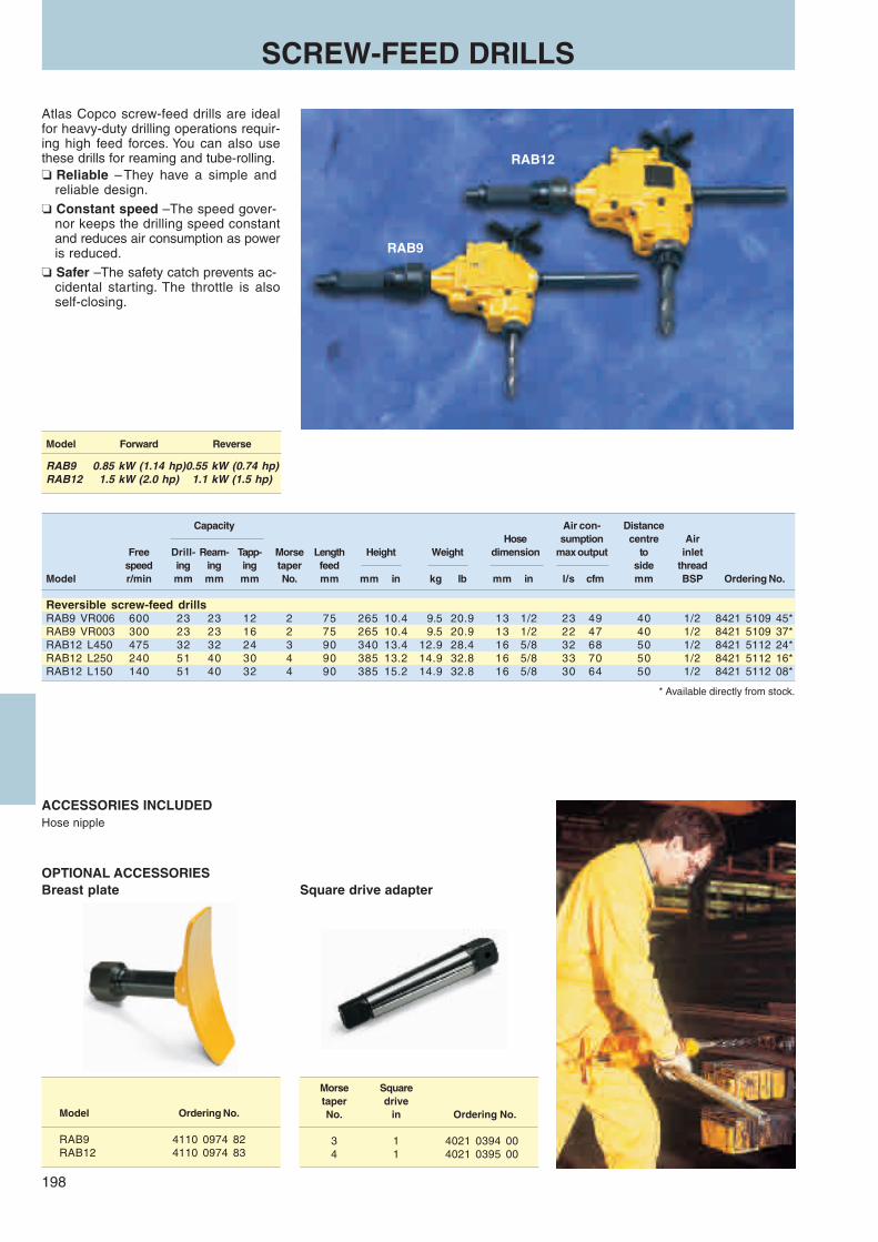
198
RAB12
RAB9
SCREW-FEED DRILLS
Atlas Copco screw-feed drills are idealfor heavy-duty drilling operations requir-ing high feed forces. You can also usethese drills for reaming and tube-rolling.❏ Reliable – They have a simple and
reliable design.❏ Constant speed – The speed gover-
nor keeps the drilling speed constantand reduces air consumption as poweris reduced.
❏ Safer – The safety catch prevents ac-cidental starting. The throttle is alsoself-closing.
* Available directly from stock.
Model Ordering No.
RAB9 4110 0974 82RAB12 4110 0974 83
Morse Squaretaper driveNo. in Ordering No.
3 1 4021 0394 004 1 4021 0395 00
Model Forward Reverse
RAB9 0.85 kW (1.14 hp)0.55 kW (0.74 hp)RAB12 1.5 kW (2.0 hp) 1.1 kW (1.5 hp)
Capacity Air con- DistanceHose sumption centre Air
Free Drill- Ream- Tapp- Morse Length Height Weight dimension max output to inletspeed ing ing ing taper feed side thread
Model r/min mm mm mm No. mm mm in kg lb mm in l/s cfm mm BSP Ordering No.
Reversible screw-feed drillsRAB9 VR006 600 23 23 12 2 75 265 10.4 9.5 20.9 13 1/2 23 49 40 1/2 8421 5109 45*RAB9 VR003 300 23 23 16 2 75 265 10.4 9.5 20.9 13 1/2 22 47 40 1/2 8421 5109 37*RAB12 L450 475 32 32 24 3 90 340 13.4 12.9 28.4 16 5/8 32 68 50 1/2 8421 5112 24*RAB12 L250 240 51 40 30 4 90 385 13.2 14.9 32.8 16 5/8 33 70 50 1/2 8421 5112 16*RAB12 L150 140 51 40 32 4 90 385 15.2 14.9 32.8 16 5/8 30 64 50 1/2 8421 5112 08*
ACCESSORIES INCLUDEDHose nipple
OPTIONAL ACCESSORIESBreast plate Square drive adapter

199
Automaticdrilling and
tapping units
More mechanization in yourdrilling operations
Simple, cost effective. Atlas Copco automaticdrilling and tapping units cut costs by reducingmachining time in ancillary equipment, or inhighly automated special machines. Modulardesigns allow the units to be easily replaced,transferred to other machines, or combined toform new special-purpose machines.
Contents PageAutomatic drilling and tapping units ............. 200
Dimension sketches .................................... 204
!199.pmd 11/20/2003, 3:51 PM199

200
LBL45
LBL35
LBL25
AUTOMATIC DRILLING AND TAPPING UNITS
These units are available in three sizes,LBL25, LBL35 and LBL45, each sizecovering a specific diameter range, to-tally up to 20 mm in steel.
The basic units can be fitted with dif-ferent chucks, twin heads for simultane-ous drilling of two holes and attachmentsfor chip removal and tapping.❏ Highly dependable – LBL drilling and
tapping units feature quick and pre-cise clamping, making them highlydependable.
❏ Easy to build together – Several holescan be drilled in a single operationsince several of these compact unitscan easily be built together.
❏ Low noise level – The units have alow noise level as the exhaust air isdischarged through silencers insidethe protective casing.
CapacityMax Air consumption
Alumi- Feed output Feed Free WeightSteel nium force stroke speed Max output Free speed
Model mm mm N kW hp mm r/min kg lb l/s cfm l/s cfm Ordering No.
Automatic drilling and tapping unitsLBL25E 220 1.2 2.0 350 0.22 0.3 80 21000 3 6.6 5.2 11 5.8 12 8421 9208 47LBL25E 049 3.2 5.0 350 0.22 0.3 80 4600 3 6.6 5.2 11 5.8 12 8421 9208 55LBL25E 022 5.0 6.5 350 0.22 0.3 80 2100 3 6.6 5.2 11 5.8 12 8421 9208 63LBL25E 011 8.0 10.0 350 0.22 0.3 80 1100 3 6.6 5.2 11 5.8 12 8421 9208 71LBL35E 190 – 2.0 1050 0.33 0.5 80 19000 7 15.0 9.5 21 10.6 22 8421 9308 53LBL35E 054 3.0 5.0 1050 0.33 0.5 80 5400 7 15.0 9.5 21 10.6 22 8421 9308 46LBL35E 030 5.0 7.0 1050 0.33 0.5 80 3000 7 15.0 9.5 21 10.6 22 8421 9308 38LBL35E 014 8.0a 10.0b 1050 0.33 0.5 80 1400 7 15.0 9.5 21 10.6 22 8421 9308 12LBL35E 007 11.0c 13.0d 1050 0.33 0.5 80 700 16 15.0 9.5 21 10.6 22 8421 9308 04LBL45E 025 – 10.0 2500 0.80 1.1 120 2500 16 35.0 20.0 44 9.0 19 8421 9408 52LBL45E 015 7.0 14.0 2500 0.80 1.1 120 1500 16 35.0 20.0 44 9.0 19 8421 9408 45LBL45E 010 10.0 16.0 2500 0.80 1.1 120 1000 16 35.0 20.0 44 9.0 19 8421 9408 37LBL45E 007 14.0c 22.0d 2500 0.80 1.1 120 700 16 35.0 20.0 44 9.0 19 8421 9408 29LBL45E 005 16.0d 22.0e 2500 0.80 1.1 120 550 16 35.0 20.0 44 9.0 19 8421 9408 11LBL45E 003 20.0e 32.0f 2500 0.80 1.1 120 320 16 35.0 20.0 44 9.0 19 8421 9408 03
Recommended max tappping size: a M4 b M5 c M8 d M10 e M12 f M16

201
LBL45
14.010.0 16.0 22.0 (M12) 32.0 (M16)
010 007 005 003
— 7.0 14.0 (M8)10.0 16.0 (M10) 20.0 (M12)
025 015
LBL35
5.02.0 7.0 10.0 (M5) 13.0 (M10)
030 014 007— 3.0 5.0 8.0 (M4) 11.0 (M8) 190 054
5.02.0 6.5 10.0
022 0111.2 3.2 5.0 8.0220 049
LBL25
SELECTION GUIDE
AluminiumSteel

202
Model Ordering No.
LBL35 4130 1950 81LBL45 4130 1950 82
LBL25
Designation Ordering No.
Hydraulic damper 4130 1844 80(feed stroke 65 mm)
Key chuck (0-6.5 mm) 4021 0283 00Key chuck (2-10 mm) 4021 0416 00
LBL35
Designation Ordering No.
Hydraulic damper 4130 1844 80(feed stroke 65 mm)
Key chuck (2.0-13.0 mm) 4021 0452 00
Sleeve chuck (2.0-9.5 mm) 4021 0459 00
Twin spindle head, speed ratio 1:1,centre to centre adjustmentrange12.7-63.5 mm 4130 1363 84
Other multiple heads on requestTapping unit, M2-M7SPD3, Taper socket J33 4130 1938 00Holder for tapping unit SPD3 4130 1787 00Collet 2.5-5 mm 4021 0412 00Collet 5-6.3 mm 4021 0413 00Tapping unit, M3-M12SPD5, Tapping Socket J33 4130 1939 00Holder for tapping unit SPD5 4130 1860 00Collet 3.3-6.8 mm 4021 0337 00Collet 4.5-8.7 mm 4021 0336 00Collet 6-10 mm 4021 0456 00
Model Ordering No.
LBL35, -45 4130 1961 80
To be used together with the hydraulic damper.
LBL45Designation Ordering No.
Hydraulic damper 4130 1895 80(feed stroke 110 mm)
Key chuck (3.2-16.0 mm) 4021 0423 00
Sleeve chuck (2.0-9.5 mm) 4021 0458 00No. 2 Morse taper socket 4130 1080 00
No. 3 Morse taper socket 4130 1079 00Twin spindle head, speed ratio 1:1,centre to centre adjustmentrange19-95 mm 4130 1364 82
Other multiple heads on request
Tapping unit, M15-M18SPD7, Taper socket, J3 4130 1940 00Holder for tapping unit SPD7 4130 1773 00Collet 6-10 mm 4023 1059 00
Hydraulic damperProgrammed damping device
OPTIONAL ACCESSORIES
Chip removal attachments
Key chuck
Sleeve chuck
Morse taper socket
Tapping unit
Twin spindle head

203
L
M ØD
C D
FE
B A
D C
E
B
I
H
E
HF
G D
DC
A
AA
A
Collets for Twin head LBL35Size Size Size Size Sizemm Ordering No. mm Ordering No. mm Ordering No. mm Ordering No. mm Ordering No.
1.0 4130 1367 00 2.2 12 3.4 24 4.6 36 5.8 481.1 01 2.3 13 3.5 25 4.7 37 5.9 491.2 02 2.4 14 3.6 26 4.8 381.3 03 2.5 15 3.7 27 4.9 39 6.0 4130 1367 501.4 04 2.6 16 3.8 28 6.1 511.5 05 2.7 17 3.9 29 5.0 4130 1367 40 6.2 521.6 06 2.8 18 5.1 41 6.3 531.7 07 2.9 19 4.0 4130 1367 30 5.2 42 6.4 541.8 08 4.1 31 5.3 43 6.5 551.9 09 3.0 4130 1367 20 4.2 32 5.4 44
3.1 21 4.3 33 5.52.0 4130 1367 10 3.2 22 4.4 34 5.62.1 11 3.3 23 4.5 35 5.7
Collets for Sleeve chuck LBL35/45 Twin head LBL45
Size Size Size Size Sizemm Ordering No. mm Ordering No. mm Ordering No. mm Ordering No. mm Ordering No.
2.0 4130 1561 00 3.6 16 5.1 31 6.7 47 8.2 622.1 01 3.7 17 5.2 32 6.8 48 8.3 632.2 02 3.8 18 5.3 33 6.9 49 8.4 642.3 03 3.9 19 5.4 34 8.5 652.4 04 5.5 35 7.0 4130 1561 50 8.6 662.5 05 4.0 4130 1561 20 5.6 36 7.1 51 8.7 672.6 06 4.1 21 5.7 37 7.2 52 8.8 682.7 07 4.2 22 5.8 38 7.3 53 8.9 692.8 08 4.3 23 5.9 39 7.4 542.9 09 4.4 24 7.5 55 9.0 4130 1561 70
4.5 25 6.0 4130 1561 40 7.6 56 9.1 713.0 4130 1561 10 4.6 26 6.1 41 7.7 57 9.2 723.1 11 4.7 27 6.2 42 7.8 58 9.3 733.2 12 4.8 28 6.3 43 7.9 59 9.4 743.3 13 4.9 29 6.4 44 9.5 753.4 14 6.5 45 8.0 4130 1561 603.5 15 5.0 4130 1561 30 6.6 46 8.1 61
TIP MOUNTDimensions, mm
MaxModel stroke L D M Ordering No.
LBL35 73 159 60 M56x1.5L 4140 0090 80LBL45 110 215 80 M56x1.5L 4140 0092 80
DRILL GUIDE (Screw mount)A B C D E F G H I Ordering No.
4a, 5, 6, M56x 60 39 25 6.2 4140 0044 04,7, 8, 10, 1.5L (2.36) (1.54) (0.98) (0.24) -05, -06, -07,12, -08, -10, -12,18, 22, -18, -22,26 -26
a Dimensions mentioned under A refer to the outside diameter for drill guide bushings.
DRILL GUIDE (Bayonet mount)
A B C D E F G H I Ordering No.
4a, 5, 6, M56x 60 30 37 40h8 6.2 4140 0058 04,7, 8, 10, 1.5L (2.36) (1.18) (1.46) (1.57) (0.31) -05, -06, -0712, -08, -10, -12,18, 22, 26 -18, -22, -26
56 36 15 6.5 67 40F8 4140 0059 80(2.20) (1.50) (0.59) (0.26) (2.64) (1.57)
a Dimensions mentioned under A refer to the outside diameter for drill guide bushings.
ACCESSORIES

204
1
2
3
4
5
6
7
5
Ø 3
0
Ø 3
7
UNF 3/8" -24-2A Ø 4
5H10
14.1 2.6159.2
280
32257.6
30.1
8
1/8" BSP 1/8" BSP1/4" BSP
5.5
550
+ 0,0
2
121.
5
137.
5
55
20
M5
8
5039
14H9
7
347 min. 50
M520
MOUNTINGSOrdering No.
Ref. No. Designation LBL25, LBL35 LBL45
1 Base plate 4140 0077 80 4140 0081 80
2 Base plate 4140 0080 80 4140 0084 80
3 Column mount 4140 0050 00
4 Side mount 4140 0047 80 4140 0018 80
5 Crossmount 4140 0048 80 4140 0029 80
6 Column socket500 mm long 4140 0051 01250 mm long 4140 0051 02600 mm long 4140 0019 02300 mm long 4140 0019 01
7 Column500 mm long 4140 0052 01600 mm long 4140 0020 02300 mm long 4140 0020 01
8 Locking bar 4140 0078 00a 4140 0082 00a
9 Locking bar 4140 0079 00a 4140 0083 00a
a Two per unit.
Dimensions available on Auto-Cad diskette. Please contact Atlas Copco.
DIMENSION SKETCH – LBL25
DIMENSION SKETCHES
Max stroke 80

205
100
80
131360
Ø6.
5Ø
12.5
3
4120
9
Ø59
.7H
9
15
Ø6H
6
103
5
68
1313 M6
4
44.8 6H6
14Ø
59.7
1008010
100
Ø59.770
Ø59
.7
4261
42
3.8
10
Ø6.
5
Ø11
21js10
Ø6P
9
1040
4010
0
10 1313100
2
5.5
14 H958 ± 0.02
69
11
M6
9
Ø 1
20
10 -01 = 500-02 = 250
Ø59
.7H
11Ø
59.7
H11
6
7
500
3.8
10
1
8
Ø6.
5
Ø6P
9Ø
11
1010021
js10
70 1313
80
11
5.5
14 H958 ± 0.2
69
58 ± 0.298
Ø6.
5
13 13
85
4040
63
Ø26
3980
∅46
~82
2.5∅55
H100
44
144159.2
347.5
100 77
82.8
∅12
.5 14~188
Ø69
~16348~5
Ø27
Ø52
.5
~3 39~124
SPD 5 SPD 3
145
50
70
25255
25±0
.02
55
M6
8
4000
82.8
M6
M6M
M6M
14H9H14H9
Max
63.
5
Min. 50
77m
m
23.6 mm ∅
18.6 mm ∅
7 mm
43.6
mm
Dimensions available on Auto-Cad diskette. Please contact Atlas Copco.
DIMENSION SKETCH – LBL35
DIMENSION SKETCH – Mountings for LBL25E and -35E
DIMENSION SKETCHES
Spanner 19Spanner 20
Hydraulic damper
Max stroke 80Taperedmountkona33JT
Sleeve chuck
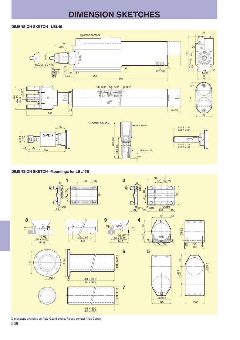
206
1 2
3535
80 30
95
Ø14
6
Ø8.
5Ø
6P9
2915 js10
Ø14
6
Ø8.
5
2915 js10
4040
35 3570
100
140Ø6P9
8
14
14 H980 ± 0.02
94.5
5.5
102±0.02138
80 ± 0.0294.5
14
9
14 H9
5.5
M6
4
454.7
59
14
35 35
6H9
98
Ø14
2915 js10
4040
3570
140
M6
98
Ø89
.5
1008010
118
Ø8.5
Ø 1
40
12 -01 = 300-02 = 600
Ø89
.5H
11
6
-01 = 300-02 = 600
Ø89
.5H
11
7
Ø89
.5
59+0
.191
-0
100Ø 89.5
100
5
Ø59
Ø65
7
1/8" BSP
30
50822558.5
3.7Ø
~10172.5
Min 70
124
Max
95
Min
19
247
1/8" BSP 1/8" BSP3/8" BSP
18.7
24
SPD 7
Ø75
.5Ø
37
200~5 64
55 MK 2 ~146MK 3 ~166
MK 2 ~117MK 3 ~137
185
69
70±
14H9H
124
A-A-
35
10
60
M6
95
83.5
mm
26.8 mm ∅
18.6 mm ∅
7 mm
Dimensions available on Auto-Cad diskette. Please contact Atlas Copco.
DIMENSION SKETCH – LBL45
DIMENSION SKETCH – Mountings for LBL45E
DIMENSION SKETCHES
Hydralic damper
Max stroke 120TaperedmountkonaJT3
Sleeve chuck
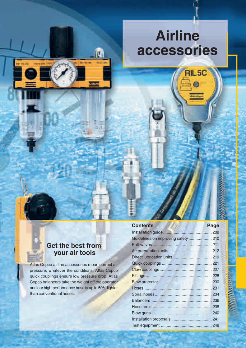
189
Airlineaccessories
Get the best from your air tools
Atlas Copco airline accessories mean correct airpressure, whatever the conditions. Atlas Copcoquick couplings ensure low pressure drop. AtlasCopco balancers take the weight off the operatorand our high-performance hose is up to 50% lighterthan conventional hoses.
Contents PageInstallation guide .......................................... 208
Guidelines on improving safety .................... 210
Ball valves ................................................... 211
Air preparation units ..................................... 212
Direct lubrication units ................................. 219
Quick couplings ........................................... 221
Claw couplings ............................................. 227
Fittings ......................................................... 228
Blow protector .............................................. 230
Hoses .......................................................... 231
Spiral hoses ................................................. 234
Balancers .................................................... 236
Hose reels ................................................... 238
Blow guns .................................................... 240
Installation proposals ................................... 241
Test equipment ............................................ 248

208
INSTALLATION GUIDE
AIR PREPARATION UNITS, MINI 1/4", MIDI 1/2" and MAXI 1"The most common way to choose between these three typesis to select MIDI wherever possible (this will cover approxi-mately 90% of all the applications). MIDI is suitable for allkinds of assembly tools, percussive tools, drills, nibblers andsaws. MIDI can also be used for small grinders.
MAXI can be used as an alternative when necessary. If thetools are major air consumers, large grinders for instance, 80 %require MAXI units, and it might be a good idea to install MAXIon all work sites.
MINI can be used as an alternative to the MIDI when usingtools with low air consumption. MINI is also the usual systemchosen for use with pneumatic components.
FILTER / REGULATORF/R units are recommended in every case where both filtersand regulators are needed. Combined units work as well asseparate units, filtering and regulating properties are almostthe same as for individual units.
BALL VALVESBall valves are required when servicing airpreparation units. When claw couplings areused, ball valves are the only way to shut offthe air flow. There are two types available:BAL and BAL-1A.
Both are lubricated with silicone-freegrease, which is important when spray-paint-ing. BAL type valves can be used in any po-sition from fully open to fully closed. BAL-1Ais designed to operate either fully open orfully closed.
REGULATORThe regulator (REG) is designed to ensure the right workingpressure to the tool. A regulator is needed when high accuracyis required on the tools working pressure, this is normally thecase when using torque controlled tools, i.e. assembly tools.Too high working pressure also means unnecessarily high airconsumption.
METAL BOWL GUARDThe metal bowl guard is recommended for extra safety when apolycarbonate bowl is used (MINI and MIDI only). The guardhelps avoid accidents if the polycarbonate bowl is damagedunder pressure. MAXI units have a metal bowl as standard.
OIL-FOG LUBRICATORThe oil fog lubricator (DIM) is usedto lubricate air tools which have anormal operation time and is thestandard method of lubricating airtools. (It is not needed with lubrica-tion-free tools.)

209
DIRECT LUBRICATORIf the operation time is very short, direct lubrication at the toolis recommended. The direct lubrication unit (DOS) is con-nected to the air tool by a nylon tube which is placed insidethe air hose. This makes it possible to supply oil at theprecise point of operation.
FILTERThe filter (FIL) is used to remove water and dirt from the com-pressed air. Clean air prevents corrosion damage and wearof the air tools.
The usual type of drainage on filters is semi-automatic. Allfilters are accompanied by a kit enabling them to be convertedfrom semi-automatic to manual drainage.
By manual drainage we mean drainage by hand when thefilter bowl is full. Semi-automatic drainage takes place whenthe pressure in the bowl drops below 0.2 bar (providing theair supply is switched off regularly).
QUICK AND CLAW COUPLINGSSix different types exist: ErgoQIC 08, ErgoQIC 10, QIC 08, QIC10, QIC 15 and CLAW.
The ErgoQIC system is a ball valve coupling system offeringa higher air flow than ordinary coupling systems. The QIC systemis a normal quick coupling system with high air flows. The CLAWsystem is a large bore claw coupling system offering a veryhigh air flow.
For assembly tools, riveting hammers and drills it is recom-mended that a smaller sized coupling such as QIC 10 andErgoQIC 08 is used, but for assembly tools and drills with higherair consumption than 20 l/s it is recommended that QIC 15 orErgoQIC 10 are used.
For grinders and percussive tools it is recommended that thebigger sized couplings such as QIC 15, ErgoQIC 10 and CLAWare used. For smaller grinders with air consumption below 10 l/sErgoQIC 08 and QIC 10 can be used.
HOSESChoose hoses depending on the working environment. Whenit is hot, dirty and the hoses are laying on the floor, chooserubber hoses. For bench operations and a clean environment,use the CABLAIR. For all general operations, light grinding toheavy assembly, ordinary PVC or the POLUR hoses will do fine.
WHIP HOSESWhip hoses are recommended for use on percussive toolssuch as impact wrenches, chipping hammers and on grinderswith high levels of vibration. Couplings which are connecteddirectly to a percussive tool will be in need of replacementsooner if a whip hose is not used.
INSTALLATION GUIDE
PRESSURE CLAMPSA single lugged medium pressure clamp is recommended foruse on CABLAIR. A medium pressure clamp with screw lock-ing is recommended for PVC and POLUR hoses and smallerrubber hoses up to 16 mm. Heavy duty clamp is recommendedfor rubber hoses above 16 mm.
BLOW PROTECTORWhen a fitting comes loose from a pressurised hose,the hose starts to blow compressed air in anuncontrolled way, whipping around. This caninjure people, damage the work-piece anddestroy the environment. A way to ensurethis does not happen is to use blowprotector BLOCK.

210
GUIDELINES ON IMPROVING SAFETY
Please read the separate instructionsregarding safety which are suppliedwith all products in order to improveyour own safety!
BALL VALVE❏ Switch off the compressed air with the
ball valve when you are not working.❏ Open all ball valves gently in order to
discover improperly tightened devices.
AIR PREPARATION UNITS❏ Please check for solvents which change
the structure of polycarbonatea bowls.These solvents make the polycarbonatebrittle so it can break. Normally polycar-bonate is not easy to break. If you needto use aggressive solvents, please con-tact us and we will help you in choosingthe right equipment.
❏ Use bowl guard.An easy way to eliminate this type ofaccident is to use a bowl guard on MINIand MIDI units. The MAXI unit has a metalbowl as standard.Check that the bowls are properly tight-ened and that all units are fit togetherbefore switching on the compressed airwith the ball valve.
QUICK COUPLINGS❏ Use safety nipples if the hose is longer
than 3 metres.Quick couplings are normally very safedevices. The only time you need to im-prove the safety is when you are workingwith hoses from 16 mm diameter and up-wards or if the hose is longer than 3 me-tres. In such cases we recommend that youuse the safety nipples in order to ventilatethe air from the hose in a controlled way.Never open a quick coupling with ascrew-driver in order to ventilate the air.
CLAW COUPLINGS❏ Be very careful.Are always open and must be used verycarefully. Follow this order when workingwith claw couplings.
How to open a claw coupling:
❏ Release the claw coupling.
How to close a claw coupling:
❏ Make sure that the two claw cou-plings are mounted together.
Use claw couplings with lock nut (LNH)or use a lock spring for safer locking.
❏ Open the ball valve gently.
CLAMPS AND CONNECTIONS❏ Avoid screwdrivers when tightening.Check that they are properly tightened.Avoid screwdrivers when tightening, theycan easily slip and damage your hand.Use a wrench. If you need to use a screw-driver then mount the clamp in a vice.
HOSESWhen mounting hoses on hose nipples,use water and soap in order to make thehose slip on to the nipple.
Do not use oil. Water and soap will dryup. Remove leaking hoses. A small leak-age can quickly become a big hole.
❏ This dangerous situation can beavoided by using a blow protector.
❏ BLOCK blow protector shuts off theair flow so the risk of personal injuriesis minimized.
❏ Close the ball valve.
❏ We strongly recommend the use ofblow protector BLOCK when usingclaw couplings.
❏ When the hose has been repairedand the compressed air is switchedon again the BLOCK is automaticallyreset.
BLOW GUNS❏ Use the safety version. It eliminates
the risk of high pressure coming intodirect contact with skin.
BLOW PROTECTORA dangerous situation can arise with ahose that is accidently blowing com-pressed air in an uncontrolled way,causing it to whip.
a Polycarbonate has good chemical resistance to allsolvents except chemicals containing acetone,benzol, glycerine, some hydraulic and syntheticoils, chloroform, methyl alcohol, carbon tetrachloride(and similar solvents), carbon disulphide, per-chloroethylene, toluene, trichloroethylene, xylene(nitrocellulose, thinner), acetic acid.
❏ Run the tool so the air ventilates out.

211
H
L
D
L
H
I
D
Connection Borethread D L H
Model in BSP mm mm mm Ordering No.
BAL 08 1/4 9.5 50 41 8202 0301 05*BAL 10 3/8 9.5 50 41 8202 0302 04*BAL 15 1/2 12.5 60 43 8202 0303 03*BAL 20 3/4 19 75 55 8202 0304 02*BAL 25 1 24.5 90 64 8202 0305 01*
Connection Borethread D L H I
Model in BSP mm mm mm mm Ordering No.
BAL-1A 08 1/4 8 43 44 73 8202 0306 03*BAL-1A 10 3/8 10 50 47 73 8202 0306 11*BAL-1A 15 1/2 15 61 53 94 8202 0306 29*BAL-1A 20 3/4 20 70 57 94 8202 0306 37*BAL-1A 25 1 25 83 67.5 122 8202 0306 45*BAL-1A 32 11/4 32 100 83 150 8202 0306 52*BAL-1A 40 11/2 38 107 87 150 8202 0306 60*BAL-1A 50 2 50 129 103 193 8202 0306 78*
BALL VALVES
VALVES – BAL AND BAL-1AThe Atlas Copco valves BAL and BAL-1Aare both suitable for air, water and manyother liquids and gases due to the choiceof material.
❏ Silicone-free grease – Both are lubri-cated with silicone-free grease whichis important when spray-painting.
❏ Maximum through flow – Full borevalve to DIN standards.
❏ Housing and ball made of chrome-plated hot-stamped brass MS 58.
❏ Handle of enamelled aluminium.
DOUBLE CONNECTION
From Tothread thread
in in Ordering No.
1/8 BSPT 1/8 BSPT 9090 0100 00*1/8 BSPT 1/4 BSPT 9090 0110 00*1/4 BSPT 1/4 BSPT 9090 0120 00*1/4 BSPT 3/8 BSPT 9090 0130 00*3/8 BSPT 3/8 BSPT 9090 0140 00*3/8 BSPT 1/2 BSPT 9090 0150 00*1/2 BSPT 1/2 BSPT 9090 0160 00*1/2 BSPT 3/4 BSPT 9090 0170 003/4 BSPT 3/4 BSPT 9090 0180 003/4 BSPT 1 BSPT 9090 0190 00 1 BSPT 1 BSPT 9090 0200 00*
BUSHING
Male thread – female thread
Male Femalethread thread
in in Ordering No.
1/4 BSP 1/8 BSP 9090 0799 00*3/8 BSP 1/4 BSP 9090 0798 00*1/2 BSP 1/4 BSP 9090 1469 00*1/2 BSP 3/8 BSP 9090 0797 00*3/4 BSP 1/2 BSP 9090 0796 00*
1 BSP 3/4 BSP 9090 0795 00*
Fibre gasketFor coupling between materialwith thread and nipple
in/mm Ordering No.
M5 0657 5710 001/8 BSP 0657 5742 00*1/4 BSP 0657 5764 00*3/8 BSP 0657 5785 00*1/2 BSP 0653 0500 01*3/4 BSP 0657 5823 00*
1 BSP 0657 5830 00*
BAL – VALVES WITH NITRILE RUBBER SEALSThe BAL valves can be used in all settings between fully open and fully closed.
The balls and the seals can be replaced without the body being removed from thepiping.
Maximum working pressure: 16 bar. Working temperature range: –2 0oC to +90oC.
BAL-1A – VALVES WITH TEFLON SEALSIntended for operating either fully open or fully closed.
Maximum working pressure 16 bar (BAL-1A 40 and 50: max. 16 bar up to +100oC).Working temperature range: –30 oC to +200oC. (BAL-1A 40 and 50: at +200oC
max. working pressure is reduced to 8 bar).
* Available directly from stock.
GASKETS
For more fittings see page 228-229.
* Available directly from stock.
Male taper thread – male taper thread
* Available directly from stock.

212
A
SA
M
+
AIR PREPARATION UNITSA correct air treatment guarantees a good total economy
The only way to ensure maximum capacityand increased service life for your com-pressed air equipment is to make surethat the air you use is correctly processed.This is where Atlas Copco's MINI, MIDIand MAXI air preparation units come in.They are designed to correctly processthe air for all types of pneumatic equip-ment used in industry today. And a correctair treatment guarantees a good totaleconomy of the system.
To guarantee that the machine at theend of the airline delivers its optimumpower, each unit is designed to allow thesmallest possible pressure drop.❏ Easy to install – a modern compact
design with small installation dimen-sions.
❏ Direct assembly – which eliminatesbulky couplings.
❏ Easy to handle – simple installationand simple dismantling.
Catalogue symbols
Important standards for air preparation units
European standard EN 983 Safety of machineryAtlas Copco fulfils all of these demands regarding air preparation units MINI-K,MINI-B, MIDI-C and MAXI.International standard ISO 4414The contents of ISO 4414 are the same regarding air preparation units as thoseof EN 983, which Atlas Copco fulfils for the following air preparation units MINI-K, MINI-B, MIDI-C and MAXI.
Manual drainage Pressure gauge0-10 bar
Semi-automatic drainage
Automatic drainage
Polycarbonate bowl
Polycarbonate bowl and bowl guard
Metal bowl
Oil free outlet

213
5 10 15 25 3020 35
0.4
0.3
0.1
0.2
100
90
80
90
80
40
50
5 10 15 20 25 30 35
MIDI FIL
2
6
4
0.5 1.0 1.5 2.0 2.5
4
6
1
5
10 20 30 40 50 60 70 80
3
2
8 - 6
8 - 4
6 - 48 - 2
5 10 15 20 25 30 35
0.4
0.3
0.1
0.2
FILTER – FILWater and dirt in your compressed air sys-tem will cause extensive corrosiondamage and wear.❏ Cleaner air – Atlas Copco filters are
designed to give clean air with minimalpressure loss and a very high degreeof water separation.
❏ Longer life for your tool – Using airfilters will result in a noticeable de-crease in maintenance costs for thepneumatic equipment used.
The MIDI FIL 15C removes 97% of thewater present in the air line at 6 bar and33 l/s with a minimum pressure drop (seefig. 1 and 2). Competitors fall within theshaded field.
Fig. 1. MIDI FIL 15C – Water separation
Fig. 2. MIDI FIL 15C – Pressure drop
REGULATOR – REGAtlas Copco regulators reduce a variableprimary pressure to a practically constantsecondary pressure.❏ Good operation economy – By in-
stalling a pressure regulator you canbe assured of maintaining a good op-erating economy.
❏ No unnecessary air consumption –Many pneumatic applications do notrequire full airline pressure to operateefficiently.
Fig. 3. MIDI REG 15C-S – Secondarypressure versus flow
Flow characteristic, if the regulator is setfor a secondary pressure of 6 bar at aconstant air line pressure of 8 bar with noair flow, the secondary pressure will dropwhen air consumption starts. At a flow rateof 10 l/s for instance, the secondary pres-sure will be 5.5 bar and will remain thesame even if the air flow increases up to50 l/s (see fig. 3).
Combined air preparationunits.
LUBRICATOR – DIMAtlas Copco oil-fog lubricators ensure along, efficient and trouble-free life for yourpneumatic tools and components.❏ Correct proportion oil to air flow –
Oil fog lubrication is recommended fortools in continuous operation. The lu-bricator automatically delivers oil tothe working pneumatic unit in correctproportion to the air consumption.
Fig. 4. MIDI DIM 15C – Oil delivery
The MIDI DIM 15C begins delivering oilwhen the air flow is as low as 0.3 l/s at6 bar. Competitors fall within the shadedfield (see fig. 4).The figure shows that MIDI DIM 15C hasthe advantage of a very low pressuredrop. Competitors fall within the shadedfield (see fig. 5).
The combination unitsMINI F/R, MIDI F/R andMAXI F/R have the samefunction as FIL and REGtogether.
AIR PREPARATION UNITS
Water separation%
Air flow l/s Air flow l/s
Secondary pressurebar
Air flow l/s
Primary pressurebar
Pressure dropbar
Air flow l/s
Pressure dropbar
Air flow l/s
Fig. 5. MIDI DIM 15C – Pressure drop

214
~94 14
5
BS
P 1
/4"
40
BS
P 1
/4"
40
43
BS
P 1
/4"
~104
~115
BS
P 1
/4"
M
M
M
BS
P 1
/4"
~88
43
17
40
BS
P 1
/4"
M30x1.5
~32 BS
P 1
/4"
BS
P 1
/4"
~175
80
M30x1.5
~104
4310 ~32
BS
P 1
/4"
BS
P 1
/4"
~175
40
M30x1.5
~104
43 ~32
MINI-K – 1/4" BSP
Air preparation unit MINI-K main appli-cation is to prepare the air for pneumaticcomponents. MINI-K has a 1/4" BSPconnection thread and the housing isof plastic.
All separate units, mounting brackets,assembly kits and pressure gauges needto be ordered separately. Please refer topage 218 for accessories. Combinationunits are delivered complete.
MINI-K Pressure1/4" BSP Max rec Filter Type of gaugeModel air flow drainage bowl (thread)
12 l/s 1/8" BSP
MINI F/R 08Ka
Ordering No. 9092 0001 21*
9 l/s
MINI F/RD 08Kb
Ordering No. 9092 0001 51*
MINI-K Pressure1/4" BSP Max rec Filter Type of gaugeModel air flow drainage bowl (thread)
12 l/s
MINI FIL 08K-Ba
Ordering No. 9092 0000 01
10 l/s 1/8" BSP
MINI REG 08Ka
Ordering No. 9092 0000 61*
9 l/s
MINI DIM 08Ka
Ordering No. 9092 0000 91
a Accessories page 218.b Mounting bracket, assembly kit and gauge are included.
* Available directly from stock.
LUB
RIC
ATO
RR
EG
ULA
TOR
FIL
TE
R
FIL
TE
R/R
EG
ULA
TOR
+LU
BR
ICAT
OR
FIL
TE
R/R
EG
ULA
TOR

215
M
M
BS
P 1
/4"
BS
P 1
/4"
~185
145
Ø 35.5
~115
50 ~32
29
M
SA
Max. 30x1.5
79
40
40
BS
P 1
/4"
~32
BS
P 1
/4"
50
50
BS
P 1
/4"
~115
~140
BS
P 1
/4"
BS
P 1
/4"
~92
50
22.5
50
BS
P 1
/4"
35.5
~32
~97 13
6
BS
P 1
/4"
BS
P 1
/4"
50
50
BS
P 1
/4"
~185
35.5
~115
50 ~32
50
BS
P 1
/4"
BS
P 1
/4"
~185
95
Ø 35.5
~115
50 ~32
29
M
MSA
SA
SA
MINI-B – 1/4" BSP
Air preparation unit MINI-B main appli-cation is to prepare the air for pneumaticcomponents and can also be used as acomplement for pneumatic tools with lowair consumption, i.e. smaller screwdrivers.MINI-B has a 1/4" BSP connection threadand the housing is of metal.
All separate units, mounting brackets,assembly kits and pressure gauges needto be ordered separately. Please refer topage 218 for accessories. Combinationunits are delivered complete.
MINI-B Pressure1/4" BSP Max rec Filter Type of gaugeModel air flow drainage bowl (thread)
12 l/s
MINI FIL 08B-Ba
Ordering No. 9093 0032 11*
12 l/s
MINI FIL 08B-Ca
Ordering No. 9093 0032 41*
13 l/s
MINI FIL 08B-Da
Ordering No. 9093 0032 71*
9 l/s 1/8" BSP
MINI REG 08Ba
Ordering No. 9093 0033 01*
9 l/s 1/8" BSP
Regulator with lock pin
MINI REG 08B-LPa
Ordering No. 9093 0073 21*
8 l/s 1/8" BSP
Regulator, panel mounted
MINI REG 08Pa
Ordering No. 9093 0000 31*
MINI-B Pressure1/4" BSP Max rec Filter Type of gaugeModel air flow drainage bowl (thread)
12 l/s
MINI DIM 08Ba
Ordering No. 9093 0033 31*
12 l/s
MINI DIM 08B-Da
Ordering No. 9093 0033 61*
9 l/s 1/8" BSP
MINI F/R 08B-Ba
Ordering No. 9093 0033 91*
9 l/s 1/8" BSP
MINI F/R 08B-Ca
Ordering No. 9093 0034 21*
9 l/s
MINI F/RD 08B-Bb
Ordering No. 9093 0034 51*
9 l/s
MINI F/RD 08B-Cb
Ordering No. 9093 0034 81*
9 l/s
MINI FRD 08B-Bb
Ordering No. 9093 0062 11*
9 l/s
MINI FRD 08B-Cb
Ordering No. 9093 0062 41*
RE
GU
LATO
RR
EG
ULA
TOR
FIL
TE
R
FIL
TE
R+
RE
GU
LATO
R+
LUB
RIC
ATO
RF
ILT
ER
/RE
GU
LATO
R+
LUB
RIC
ATO
RF
ILT
ER
/RE
GU
LATO
RLU
BR
ICAT
OR
* Available directly from stock.a Accessories page 218. b Mounting bracket, assembly kit and gauge are included.
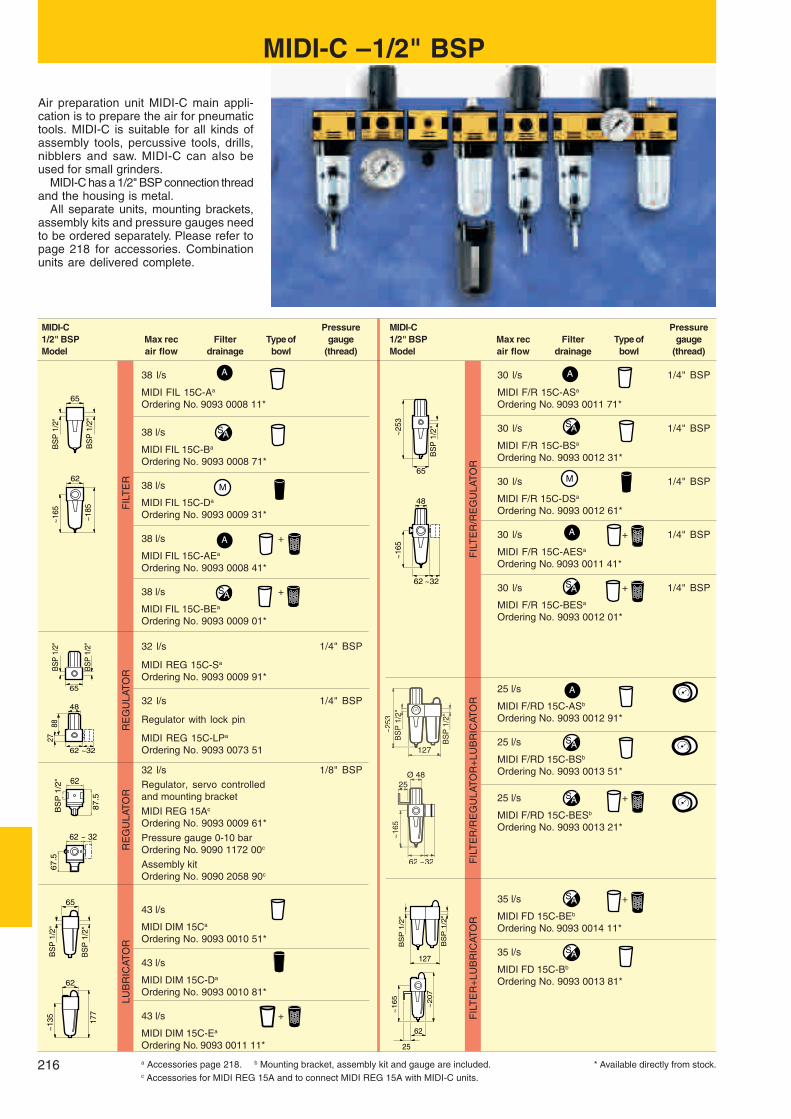
216
65
62
BS
P 1
/2"
~165
~185
BS
P 1
/2"
MM
62
BS
P 1
/2"
67.5
~ 32
62
87.5
BS
P 1
/2"
62
8827
65
BS
P 1
/2"
48
~32
BS
P 1
/2"
~253
127
~165
62 ~32
BS
P 1
/2"
BS
P 1
/2"
~2
07
127
~1
65
62
25
BS
P 1
/2"
~253
48
~165
62 ~32
65
~135 17
7
BS
P 1
/2"
BS
P 1
/2"
65
62
A
SA
A
A
A
A
SA
SA
SA
SA
SA
SA
SA
MIDI-C – 1/2" BSP
Air preparation unit MIDI-C main appli-cation is to prepare the air for pneumatictools. MIDI-C is suitable for all kinds ofassembly tools, percussive tools, drills,nibblers and saw. MIDI-C can also beused for small grinders.
MIDI-C has a 1/2" BSP connection threadand the housing is metal.
All separate units, mounting brackets,assembly kits and pressure gauges needto be ordered separately. Please refer topage 218 for accessories. Combinationunits are delivered complete.
MIDI-C Pressure1/2" BSP Max rec Filter Type of gaugeModel air flow drainage bowl (thread)
30 l/s 1/4" BSP
MIDI F/R 15C-ASa
Ordering No. 9093 0011 71*
30 l/s 1/4" BSP
MIDI F/R 15C-BSa
Ordering No. 9093 0012 31*
30 l/s 1/4" BSP
MIDI F/R 15C-DSa
Ordering No. 9093 0012 61*
30 l/s + 1/4" BSP
MIDI F/R 15C-AESa
Ordering No. 9093 0011 41*
30 l/s + 1/4" BSP
MIDI F/R 15C-BESa
Ordering No. 9093 0012 01*
25 l/s
MIDI F/RD 15C-ASb
Ordering No. 9093 0012 91*
25 l/s
MIDI F/RD 15C-BSb
Ordering No. 9093 0013 51*
25 l/s +
MIDI F/RD 15C-BESb
Ordering No. 9093 0013 21*
35 l/s +
MIDI FD 15C-BEb
Ordering No. 9093 0014 11*
35 l/s
MIDI FD 15C-Bb
Ordering No. 9093 0013 81*
MIDI-C Pressure1/2" BSP Max rec Filter Type of gaugeModel air flow drainage bowl (thread)
38 l/s
MIDI FIL 15C-Aa
Ordering No. 9093 0008 11*
38 l/s
MIDI FIL 15C-Ba
Ordering No. 9093 0008 71*
38 l/s
MIDI FIL 15C-Da
Ordering No. 9093 0009 31*
38 l/s +
MIDI FIL 15C-AEa
Ordering No. 9093 0008 41*
38 l/s +
MIDI FIL 15C-BEa
Ordering No. 9093 0009 01*
32 l/s 1/4" BSP
MIDI REG 15C-Sa
Ordering No. 9093 0009 91*
32 l/s 1/4" BSP
Regulator with lock pin
MIDI REG 15C-LPa
Ordering No. 9093 0073 51
32 l/s 1/8" BSPRegulator, servo controlledand mounting bracket
MIDI REG 15Ac
Ordering No. 9093 0009 61*Pressure gauge 0-10 barOrdering No. 9090 1172 00c
Assembly kitOrdering No. 9090 2058 90c
43 l/s
MIDI DIM 15Ca
Ordering No. 9093 0010 51*
43 l/s
MIDI DIM 15C-Da
Ordering No. 9093 0010 81*
43 l/s +
MIDI DIM 15C-Ea
Ordering No. 9093 0011 11*
LUB
RIC
ATO
RR
EG
ULA
TOR
RE
GU
LATO
RF
ILT
ER
FIL
TE
R+
LUB
RIC
ATO
RF
ILT
ER
/RE
GU
LATO
R+
LUB
RIC
ATO
RF
ILT
ER
/RE
GU
LATO
R
* Available directly from stock.a Accessories page 218. b Mounting bracket, assembly kit and gauge are included.c Accessories for MIDI REG 15A and to connect MIDI REG 15A with MIDI-C units.

217
BS
P 1
/2"
BS
P 1
/2"
~253
189
A Ø 48
~165
62 ~32
25
90
90
BS
P 1
"
~315
~345
BS
P 1
"B
SP
1"
~ 180
90
42.5
90
BS
P 1
"
62
~32
~190 25
5
BS
P 1
"
BS
P 1
"
90
90
BS
P 1
"
~450
62
~313
90 ~32
BS
P 1
"
BS
P 1
"~4
50
18040 40
BS
P 1
"
BS
P 1
"~4
50
27040 40
SA
A
SA
SASA
SA
SA
MIDI-C Pressure1/2" BSP Max rec Filter Type of gaugeModel air flow drainage bowl (thread)
43 l/s
MIDI FRD 15C-ASb
Ordering No. 9093 0014 71*
43 l/s
MIDI FRD 15C-BSb
Ordering No. 9093 0015 31*
MIDI-C Pressure1/2" BSP Max rec Filter Type of gaugeModel air flow drainage bowl (thread)
43 l/s +
MIDI FRD 15C-AESb
Ordering No. 9093 0014 41*
43 l/s +
MIDI FRD 15C-BESb
Ordering No. 9093 0015 01*
MAXI – 1" BSPAir preparation unit MAXI main applica-tion is to prepare the air for pneumatictools which are large air consumers. MAXIcan be used for large air consumers, i.e.big grinders. MAXI has a 1" BSP connec-tion thread and the housing is metal.
All separate units, mounting brackets,assembly kits and pressure gauges needto be ordered separately. Please refer topage 218 for accessories. Combinationunits are delivered complete.
MIDI-C – 1/2" BSP
MAXI Pressure1" BSP Max rec Filter Type of gaugeModel air flow drainage bowl (thread)
80 l/s 1/4" BSP
MAXI F/R 25A-Ba
Ordering No. 9093 0019 51*
67 l/s
MAXI F/RD 25A-Bb
Ordering No. 9093 0019 81*
67 l/s
MAXI FRD 25A-Bb
Ordering No. 9093 0020 11*
MAXI Pressure1" BSP Max rec Filter Type of gaugeModel air flow drainage bowl (thread)
105 l/s
MAXI FIL 25A-Ba
Ordering No. 9093 0018 31*
85 l/s 1/4" BSP
MAXI REG 25Aa
Ordering No. 9093 0018 91*
85 l/s 1/4" BSP
Regulator with lock pinMAXI REG 25A-LPa
Ordering No. 9093 0073 81*
45 l/s
MAXI DIM 25Aa
Ordering No. 9093 0019 21*
FIL
TE
R+
RE
GU
LATO
R+
LUB
RIC
ATO
R
FIL
TE
R+
RE
GU
LATO
R+
LUB
RIC
ATO
R
LUB
RIC
ATO
RR
EG
ULA
TO
RF
ILT
ER
* Available directly from stock.a Accessories page 218. b Mounting bracket, assembly kit and gauge are included.
FIL
TE
R+
RE
GU
LAT
OR
+F
ILT
ER
/RE
GU
LAT
OR
+F
ILT
ER
/LU
BR
ICAT
OR
LUB
RIC
ATO
RR
EG
ULA
TOR

218
MINI-K MINI-B MIDI-C MAXICOMMON ACCESSORIES Are included in combination units (FD, FTD, F/RD and FRD).
Common accessories have to be ordered separately for separate units.
Mounting Mounting Mounting Mountingbracket kit bracket kit bracket kit bracket kit9090 1902 00* 9092 0063 01* 9090 1655 80* 9090 1852 90*
Assembly kit Assembly kit Assembly kit Assembly kit9090 1901 90* 9092 0062 71* 9090 1654 00* 9090 1849 90*
FILTER (FIL) ACCESSORIES 30 µm filter element is included with all filters.
30 µm filter 30 µm filter 30 µm filterelement element element9092 0063 31 9090 2064 00* 9090 1841 00*(FIL)
9092 0025 81*(F/R)
30 µm filter 5 µm filter 5 µm filter 5 µm filterelement element element element9090 1898 00 9092 0063 61 9090 2065 00* 9090 1846 00*(FIL)
9092 0026 11*(F/R)
Bowl guard Bowl guard9092 0063 91* 9090 1717 00*
REGULATOR (REG) ACCESSORIES Pressure gauge 0-10 bar is included in the combination units (F/RD and FRD).Pressure gauge has to be ordered separately for separate units.
Pressure gauge:0-10 bar Ø 40 mm9090 1907 00* Pressure gauge: Pressure gauge:
0-10 bar Ø 50 mm 0-10 bar Ø 50 mm 0-10 bar Ø 63 mmPressure gauge: 9090 1172 00* 9090 2052 00* 9090 0238 00*
0-10 bar Ø 40 mm 0-16 bar Ø 50 mm 0-16 bar Ø 50 mm 0-16 bar Ø 63 mm9090 1907 00* 9090 1657 00* 9090 2053 00* 9090 0239 00*
Panel mounting Panel mounting Panel mountingpressure gauge: pressure gauge: pressure gauge:0-10 bar 0-10 bar 0-10 bar9090 1173 00* 9090 1173 00* 9090 1173 00*
For regulator -LP For regulator -LP For regulator -LPKey lock Key lock Key lock9092 0074 11* 9092 0074 11* 9092 0074 11*
LUBRICATOR (DIM) ACCESSORIES
Air distribution Air distribution Air distribution Air distribution block kit block kit block kit block kit 9090 1900 90 9092 0064 51* 9090 1719 00* 9090 1851 90*
Bowl guard Bowl guard9092 0063 91* 9090 1717 00*
Glass sight dome Glass sight dome Glass sight dome9090 1121 00* 9090 1121 00* 9090 1873 00
FIL/REG (F/R) ACCESSORIES Please see filter (FIL) and regulator (REG) accessories for appropriate accessories.
* Available directly from stock.

219
DIRECT LUBRICATION UNITS
SINGLE-POINT LUBRICATOR DOSOLAccurate lubrication for tools in intermit-tent service.
The Atlas Copco DOSOL system for di-rect lubrication is based on an injectorpump which meters out the oil in exactdoses, actuated by pulses of compressedair. The oil dosage can be regulated froma fraction of a drop to a full drop.❏ Exact amount – Precision injector
adjustable for exact amount of oil.❏ Adjustable dosing – Counter allows
lubrication every first, fifth or tenth start.❏ Oil directly at the tool – The oil is
conveyed through a capillary tube di-rectly to the lubrication point.
For supplying lubricant to a single tool.Counter included as standard.
A single-point lubricator (SPL) consistsof an injector pump fitted to a valve body,converting interruptions in compressed airflow into pulses. In the majority of cases,an oil bowl is fitted on each lubricator. Apossible arrangement also consists of ashared oil container for several lubrica-tors, each of which supplies oil to one tool,for example on an assembly line.
Every DOSOL SPL-unit can be finelytuned to inject from 1 to 1/10 th of a drop
of oil in 40 steps (30 to 3 mm3). This helpsto minimize the oil dose. Every DOSOLSPL unit includes as standard a counterwith a switch that allows the lubricator tooperate every first, fifth or tenth toolcycles.
The adjusting knob features a positive
stop at both maximum and minimum set-tings which means that a zero setting isnot possible.
The preset quantity of oil is supplied tothe tool through a smallbore nylon tubeinside the air hose. 7.5 m of oil-filled ny-lon tubing is included as standard.
DOUBLE CONNECTION
From Tothread thread
in in Ordering No.
1/2 BSPT 1/2 BSPT 9090 0160 00*1/2 BSPT 3/4 BSPT 9090 0170 00*
For more fittings see page 228-229.
a At 6 bar and DP = 0.2 bar.b With counter and 7.5 m oil-filled nylon tubing.c With 0.3 l oil container counter and 7.5 m oil-filled nylon tubing.
Male taper thread – male taper thread
OPTIONAL ACCESSORIES
Designation Ordering No.
Nylon tubing 3.2 mmoutside diameter–7.5 m, oil-filled 9090 1418 00*–7.5 m, without oil 9090 1419 00*–100 m, with oil 9090 1420 00*
Barbed nipple for joining of3.2 mm tubes 9090 1423 00*
Check valve for outer end of nylon tubingdia ext. 3.2 mm 9090 2050 00
Connection Working Temperaturethread Air flow l/s pressure bar range oCBSP
Model in min maxa min max min max Ordering No.
DOS 15B-Cb 1/2 2.3 45 3.2 10 –30 o +60o 8202 4201 73*DOS 15B-CRc 1/2 2.3 45 3.2 10 –30 o +60o 8202 4202 72*DOS 20B-Cb 3/4 2.3 53 3.2 10 –30 o +60o 8202 4201 81*DOS 20B-CRc 3/4 2.3 53 3.2 10 –30 o +60o 8202 4202 80*
Single-point lubricator, DOS
* Available directly from stock.

220
1
2 3
4
41432
3
3
11
12
13
5 6 7 8
9
5
13
10
11
12
12
15
16
22
19
63.5115
NOTE: When the counterTEN is used in MPLinstallations an in-termediate, blackplastic part is used(supplied with allTEN counters) be-tween BASE andTEN.
MULTIPLE-POINT LUBRICATORDOSOLFor supplying lubricant to an unlimitednumber of lubrication points on a ma-chine or in a pneumatic system.
The DOSOL multiple-point lubricator(MPL) consists of a number of JECT 01oil metering pumps assembled into a“package” with a common BASE base-plate. A stack may contain up to ten JECT01 units. Several such assemblies maybe used together.❏ All oil pumps are supplied with oil via
the BASE from an oil container or cen-tral oil reservoir. A line for pneumaticsignals from the equipment to be lubri-cated is also connected to the BASE.
❏ The lubricant is conveyed throughsmall-bore nylon tubing which shouldbe ended with check valves.
❏ With the TEN counter the lubricatorcan be actuated every first, fifth ortenth tool cycle.
Every DOSOL MPL unit can be finelytuned to inject from 1 to 1/10 drop of oil in40 steps (30 to 3 mm3). This helps to mini-mize the oil dose. The adjusting knob fea-tures a positive stop at both maximumand minimum settings, which means thatzero setting is not possible.
Connection threadDesignation BSP in Ordering No.
BASE baseplate Plate 8202 4205 04*– Oil port 1/4– Air port 1/4Clamp– Oil port 1/4– Air port 1/4
JECT 01 oil pump Oil delivery port 1/8 8202 4203 10*
OPTIONAL ACCESSORIESRef No.in figure Designation Ordering No.
1 Oil container 0.3 l for direct mounting 9090 1415 00* 1 Oil container 0.95 l for wall mounting (1/4" BSP female) 9090 1416 00* 1 Oil container 1.9 l for wall mounting (1/4" BSP female) 9090 1417 00* 2 Check valve 1/8" BSPT 90o elbow male x 1/8" BSP female 9090 1427 00* 2 Check valve 1/8" BSPT, straight male x 1/8" BSP female 9090 1426 00* 3 Male adapter 1/8" BSPT, straight for tube outer diameter 3.2 mm 9090 1425 00* 3 Male adapter 1/8" BSPT, elbow for tube outer diameter 3.2 mm 9090 1436 00*
4 7.5 m capillary tubing outer diameter 3.2 mm prefilled with oil 9090 1418 00* 4 7.5 m capillary tubing outer diameter 3.2 mm without oil 9090 1419 00* 4 100 m capillary tubing outer diameter 3.2 mm with oil 9090 1420 00* 5 JECT 01 kita 8202 4203 10* 6 Side-ported air block kit 9090 1424 00*
7 Fibre packing for 1/8" BSP 0657 5742 00* 8 Male adapter 1/8" BSP, straight for tube outer diameter 5 mm 9090 0714 00* 9 Nylon tube outer diameter 5 mm (sold by the metre) 9030 0059 00*
10 Counter TEN kit 8202 4206 03*11 Fibre packing for 1/4" BSP 0657 5764 00*12 Male adapter 1/4" BSP, straight for tube outer diameter 8 mm 9090 0715 00*
13 BASE kit 8202 4205 04*14 Nylon tube, outer diameter 8 mm (sold by the metre) 9030 0060 00*15 Barbed nipple for joining of nylon tubes outer diameter 3.2 mm 9090 1423 00*
OPTIONAL ACCESSORIES
Designation Ordering No.
TEN-counter 8202 4206 03*When lubricating equipmentwith a very low air consumptionor very short time in operationit may be difficult to set a suffi-ciently small dose of oil. In suchcases a counter is connectedunderneath the base plateBASE. The oil pumps will thenbe actuated only on each, everyfifth or every tenth air pulse. Theair signal is connected to theclamp underneath the counter.
Side-ported air block kit 9090 1424 00*If all pumps are not to be actu-ated simultaneously, a signalblock is installed between theoil pumps in the stack. Thepumps below the signal blockwill then be actuated via thebase plate BASE and thoseabove it from a separate signalvia the signal block.
DIRECT LUBRICATION UNITS
Multiple-point lubricator, BASE, JECT 01
* Available directly from stock.
Dimensions in mm
a With high temperature Viton seals 8202 4203 15.

221
QUICK COUPLINGS
ERGOQIC and QICQuick couplings are the simple and defi-nite answer whenever tools have to bechanged or for making quick connectionsof hoses to an air outlet. Atlas Copco quickcouplings are the outstanding alternative.
The valve in each individual coupling istested for leakage prior to delivery.
Carefully selected material is used inthe couplings. This permits the use of thinmaterial which ensures maximum flowand slim outside dimensions.
Atlas Copco ErgoQIC full flow couplingsare available in two different sizes andthe QIC type in three, depending on theair flow rate. The couplings are made ofsteel and nipples of hardened and zinc-chromated steel.
All types and sizes feature❏ Exceptionally high air flow with mini-
mum pressure drop, a guarantee forhigh productivity.
❏ Built for heavy duty applications.❏ Compact dimension and low weight.❏ Long service life.❏ One-hand operation for fast and easy
tool changing.❏ Many end connections.❏ Safety feature – Safety nipples both
for QIC and ErgoQIC give no bang orrecoil when dismounting according toEN 983 and ISO 4414.
ErgoQIC 10 ErgoQIC 08 QIC 15 QIC 10 QIC 08
Valve body steel hardened X X X X X
One hand operation X X X X X
Single shut off X X X X X
Ergonomic design X X
Full flow – no restrictions X X
Extremely high air flow X
ErgoQIC 10 ErgoQIC 08 QIC 15 QIC 10 QIC 08
ErgoNIP 10
ErgoNIP 08NIP 15
NIP 10 NIP 08

222
ErgoQIC 08 and ErgoNIP 08, 18 l/s (recommended air flow at 6 bar pressure)
Size SizeConnection Coupling Connection Nippletype ErgoQIC 08 Ordering No. mm in type ErgoNIP 08 Ordering No. mm in
H – Hose H06 8202 1110 04* 6.3 1/4 H – Hose H06 8202 1210 37* 6.3 1/4H08 8202 1110 12* 8 5/16 H08 8202 1210 45* 8 5/16H10 8202 1110 38* 10 3/8 H10 8202 1210 52* 10 3/8H13 8202 1110 40* 12.5 1/2 H13 8202 1210 54* 12.5 1/2
SH – Safety Hose a SH06 8202 1210 39* 6.3 1/4SH08 8202 1210 47* 8 5/16SH10 8202 1210 50* 10 3/8SH13 8202 1210 55* 12.5 1/2
M – Male M08 8202 1110 61* 1/4 BSP M – Male M06 8202 1210 03* 1/8 BSPM10 8202 1110 79* 3/8 BSP M08 8202 1210 11* 1/4 BSPM15 8202 1110 87* 1/2 BSP M10 8202 1210 29* 3/8 BSP
M15 8202 1210 31* 1/2 BSP
F – Female F08 8202 1110 90* 1/4 BSP F – Female F08 8202 1210 60* 1/4 BSPF10 8202 1110 95* 3/8 BSP F10 8202 1210 62* 3/8 BSP
Protective cover 9090 1940 00*
a For joining hoses longer than 3 metres. * Available directly from stock.
ERGOQICThe ErgoQIC is a totally new approach toquick couplings. Upgrading any air sys-tem with ErgoQIC will give the benefit ofmore power. This leads to higher produc-tivity and to energy savings.
ErgoQIC is effective in operation andeasy to handle. Flipping the air flow on oroff is literally a pushover. The ball valveswivels through 75o for quick connection/disconnection and safe operation.
ErgoQIC 08and ErgoNIP 08
QUICK COUPLINGS
2 Straighten out 4 Bend back
1 Slot in 3 Press together
CONNECTION DISCONNECTION
Four easy steps to connect and disconnect

223
0.5
0.4
0.3
0.2
0.1
∆ bar
12 14 16 18 20 22 24 26 28 30 l/s
0.6
30 35 40 45 50 55 60 65 70 75 l/s
0.5
0.4
0.3
0.2
0.1
∆ bar0.6
TECHNICAL DATAErgoQIC 08 and ErgoQIC 10
Temperature rangeoCMax working
min max pressure bar
–10 +70 16
ErgoQIC 10 and ErgoNIP 10, 47 l/s (recommended air flow at 6 bar pressure)
Size SizeConnection Coupling Connection Nippletype ErgoQIC 10 Ordering No. mm in type ErgoNIP 10 Ordering No. mm in
H – Hose H06 8202 1120 30* 6.3 1/4 H – Hose H06 8202 1220 35* 6.3 1/4H08 8202 1120 40* 8 5/16 H08 8202 1220 43* 8 5/16H10 8202 1120 02* 10 3/8 H10 8202 1220 50* 10 3/8H13 8202 1120 10* 12.5 1/2 H13 8202 1220 68* 12.5 1/2H16 8202 1120 50* 16 5/8 H16 8202 1220 76* 16 5/8H20 8202 1120 60* 19 3/4 H20 8202 1220 77* 19 3/4
SH – Safety Hose a SH06 8202 1220 37* 6.3 1/4SH08 8202 1220 45* 8 5/16SH10 8202 1220 52* 10 3/8SH13 8202 1220 70* 12.5 1/2SH16 8202 1220 74* 16 5/8SH20 8202 1220 75* 19 3/4
M – Male M08 8202 1120 85* 1/4 BSP M – Male M08 8202 1220 01* 1/4 BSPM10 8202 1120 93* 3/8 BSP M10 8202 1220 19* 3/8 BSPM15 8202 1120 97* 1/2 BSP M15 8202 1220 27* 1/2 BSP
F – Female F08 8202 1121 00* 1/4 BSP F – Female F08 8202 1220 84* 1/4 BSPF10 8202 1121 05* 3/8 BSP F10 8202 1220 86* 3/8 BSP
F15 8202 1220 88* 1/2 BSP
Protective cover 9090 1931 00*
a For joining hoses longer than 3 metres.
ERGOQIC also feature❏ Full flow with no restrictions in the cou-
pling, which saves energy.❏ Ergonomic design, minimized connec-
tion force.❏ Automatic venting as a tool connector.❏ Safety nipple for automatic venting
when disconnecting hoses.❏ Protective cover as optional accessory
to avoid scratches.
QUICK COUPLINGS
* Available directly from stock.
FLOW CHART. ErgoQIC 08 M15 and ErgoNIP 08 M10
Air flow at an inlet pressure of 6 bar.
FLOW CHART. ErgoQIC 10 M15 and ErgoNIP 10 M15
Air flow at an inlet pressure of 6 bar.

224
QIC 08 and NIP 08, 11 l/s (recommended air flow at 6 bar pressure)
*Available directly from stock.
QICQIC couplings are the traditional but sureanswer when hoses have to be changedfrom one air tool to another or for makingfast connections to an air outlet. The smallsize of the QIC couplings makes themeasy and convenient to work with in com-bination with air tools.
QIC 08 and NIP 08
QIC 08 standard according to AmericanMilitary Standard MIL-C 4109C, inter-changeable with ARO, HANSEN, etc.
Size SizeConnection Coupling Connection Nippletype QIC 08 Ordering No. mm in type NIP 08 Ordering No. mm in
H – Hose H06 8202 1300 04* 6.3 1/4 H – Hose H06 8202 1205 18* 6.3 1/4H08 8202 1300 12* 8 5/16 H08 8202 1205 26* 8 5/16H10 8202 1300 20* 10 3/8 H10 8202 1205 34* 10 3/8
M – Male thread M08 8202 1300 38* 1/4 BSP M – Male thread M06 8202 1205 42* 1/8 BSPM10 8202 1300 46* 3/8 BSP M08 8202 1205 59* 1/4 BSP
M10 8202 1205 67* 3/8 BSP
F – Female thread F08 8202 1300 53* 1/4 BSP F – Female thread F08 8202 1205 83* 1/4 BSPF10 8202 1300 61* 3/8 BSP F10 8202 1205 91* 3/8 BSP
QUICK COUPLINGS
Four easy steps to connect and disconnect
CONNECTION DISCONNECTION
1 Slot in 3 Pull locking sleeve back
2 Press together 4 Disconnect gently
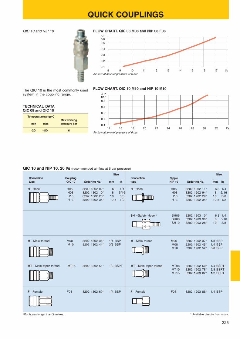
225
0.5
0.4
0.3
0.2
0.1
∆ Pbar
8 9 10 11 12 13 14 15 16 17 l/s
0.1
0.2
0.3
0.4
0.5
∆ Pbar
14 16 18 20 22 24 26 28 30 32 l/s
TECHNICAL DATAQIC 08 and QIC 10
Temperature rangeoCMax working
min max pressure bar
–20 +80 16
QIC 10 and NIP 10, 20 l/s (recommended air flow at 6 bar pressure)
Size SizeConnection Coupling Connection Nippletype QIC 10 Ordering No. mm in type NIP 10 Ordering No. mm in
H – Hose H06 8202 1302 02* 6.3 1/4 H – Hose H06 8202 1202 11* 6.3 1/4H08 8202 1302 10* 8 5/16 H08 8202 1202 94* 8 5/16H10 8202 1302 28* 10 3/8 H10 8202 1202 29* 10 3/8H13 8202 1302 34* 12.5 1/2 H13 8202 1202 34* 12.5 1/2
SH – Safety Hose a SH06 8202 1203 10* 6.3 1/4SH08 8202 1203 36* 8 5/16SH10 8202 1203 28* 10 3/8
M – Male thread M08 8202 1302 36* 1/4 BSP M – Male thread M06 8202 1202 37* 1/8 BSPM10 8202 1302 44* 3/8 BSP M08 8202 1202 45* 1/4 BSP
M10 8202 1202 52* 3/8 BSP
MT – Male taper thread MT15 8202 1302 51* 1/2 BSPT MT – Male taper thread MT08 8202 1202 60* 1/4 BSPTMT10 8202 1202 78* 3/8 BSPTMT15 8202 1203 02* 1/2 BSPT
F – Female F08 8202 1302 69* 1/4 BSP F – Female F08 8202 1202 86* 1/4 BSP
a For hoses longer than 3 metres. * Available directly from stock.
QIC 10 and NIP 10
The QIC 10 is the most commonly usedsystem in the coupling range.
QUICK COUPLINGS
FLOW CHART. QIC 08 M08 and NIP 08 F08
Air flow at an inlet pressure of 6 bar.
FLOW CHART. QIC 10 M10 and NIP 10 M10
Air flow at an inlet pressure of 6 bar.

226
0.1
0.2
0.3
0.4
0.5
∆ Pbar
30 33 36 39 42 45 48 51 54 57 l/s
Size SizeConnection Coupling Connection Nippletype QIC 15 Ordering No. mm in type NIP 15 Ordering No. mm in
H – Hose H10 8202 1304 00* 10 3/8 H – Hose H06 8202 1251 03* 6.3 1/4H13 8202 1304 18* 12.5 1/2 H08 8202 1252 28* 8 5/16H16 8202 1304 26* 16 5/8 H10 8202 1251 11* 10 3/8
H13 8202 1251 29* 12.5 1/2H16 8202 1251 37* 16 5/8
SH – Safety Hose a SH10 8202 1203 44* 10 3/8SH13 8202 1203 51* 12.5 1/2SH16 8202 1203 69* 16 5/8
M – Male thread M08 8202 1304 34* 1/4 BSP M – Male thread M10 8202 1251 45* 3/8 BSPM10 8202 1304 42* 3/8 BSP M15 8202 1251 52* 1/2 BSPM15 8202 1304 59* 1/2 BSP
MT – Male taper thread MT08 8202 1251 60* 1/4 BSPTMT10 8202 1251 78* 3/8 BSPTMT15 8202 1251 86* 1/2 BSPT
F – Female thread F15 8202 1304 67* 1/2 BSP F – Female thread F08 8202 1251 94* 1/4 BSPF10 8202 1252 02* 3/8 BSPF15 8202 1252 10* 1/2 BSP
a For hoses longer than 3 metres. * Available directly from stock.
QIC 15 and NIP 15
TECHNICAL DATAQIC 15
Temperature rangeoCMax working
min max pressure bar
–20 +80 10
European standard EN 983 Safety of machineryAtlas Copco fulfils all these demands regarding quick action couplingsQIC 10/NIP 10, QIC 15/NIP 15, ErgoQIC 08/ErgoNIP 08 and ErgoQIC 10/ErgoNIP 10.
International standard ISO 4414The contents of ISO 4414 are the same regarding quick action couplings asthose of EN 983, which Atlas Copco fulfils for the following quick couplingsQIC 10/NIP 10, QIC 15/NIP 15, ErgoQIC 08/ErgoNIP 08 and ErgoQIC 10/ErgoNIP 10.
Military Specification MIL-C-4109CAtlas Copco fulfils all these demands regarding QIC 08/NIP 08 and isinterchangeable with ARO, HANSEN, etc.
QUICK COUPLINGS
QIC 15 and NIP 15, 37 l/s (recommended air flow at 6 bar pressure)
Important standards for quick couplings
FLOW CHART. QIC 15 M15 and NIP 15 F15
Air flow at an inlet pressure of 6 bar.

227
0
0.05
0.10
0.15
0.20
∆ Pbar
0 50 100 150 200l/s
250 300
CLAWSize
Connection Coupling Boretype CLAW Ordering No. mm in B, mm
H – Hose H06 9000 0308 00* 6.3 1/4 5.0H10 9000 0309 00* 10 3/8 8.0H13 9000 0310 00* 12.5 1/2 10.5H16 9000 0311 00* 16 5/8 13.5H20 9000 0312 00* 19 3/4 17.0H25 9000 0313 00* 25 1 22.0
LNH – Lock nut, Hose LNH10 9000 0260 00* 10 3/8 8.0LNH13 9000 0261 00* 12.5 1/2 10.5LNH16 9000 0262 00* 16 5/8 13.5LNH20 9000 0263 00* 19 3/4 17.2LNH25 9000 0264 00* 25 1 22.0
M – Male thread M10 9000 0300 00* 3/8 BSP 11.2M15 9000 0301 00* 1/2 BSP 14.8M20 9000 0302 00* 3/4 BSP 19.0M25 9000 0303 00* 1 BSP 25.5
F – Female thread F10 9000 0304 00* 3/8 BSP 15.0F15 9000 0305 00* 1/2 BSP 18.6F20 9000 0306 00* 3/4 BSP 24.0F25 9000 0307 00* 1 BSP 25.0
Extra packing for For type H, M and F 9000 0000 00* (+80oC), 9000 0000 01* (+200oC)a
CLAW couplings For LNH10, -13 and -16 9000 0015 00*For LNH20 and -25 9000 0268 00* (+80oC), 9000 0319 00 (+200oC)a
Safety lock spring 3176 8640 90 25 pieces
a Viton-green. * Available directly from stock.
CLAW COUPLINGS
CLAW couplings made of dropforged, hardened steel whichcan withstand rough treatment and ensures a long life evenunder difficult conditions.The coupling head is the same for all sizes, which can thereforebe freely combined.The recommended maximum working pressure is 10 bar.❏ Large bore – machined surfaces give low air resistance and
minimum pressure drop.❏ Robust claws – withstand rough handling without deforma-
tion.❏ Locking lugs – precision-made to provide a reliable lock.❏ Special rubber packings – resistant to oil and temperature
changes. Max temperature 80oC (176oF).❏ Packing seats – lathe-turned grooves ensure a leak-proof
seal.❏ Couplings are zinc-plated and thus effectively treated against
corrosion.
ORDERING INFORMATIONThe coupling head is the same for all sizes, which can there-fore be freely combined. One packing is required for eachcoupling.
Improved working safety1. The LNH-type (CLAW coupling with lock nut) will always
give a safe locking. Use one LNH coupling with either H,M or F type of coupling
OR
2. Use safety lock spring for safe locking of H, M and F type.
For each pair of couplings one safe lock spring is required.
FLOW CHART. For 2 pieces of CLAW
Air flow at an inlet pressure of 6 bar.

228
Medium clampFor For worm drive
CABLAIR PVC, POLUR mm Ordering No.– – 8.0-14.0 0347 6102 00*– 08 11.0-17.0 0347 6103 00*– 10 11.0-17.0 0347 6103 00*– – 13.0-20.0 0347 6104 00*
16 13 15.0-24.0 0347 6105 00*20 16 19.0-28.0 0347 6106 00*– 20 22.0-32.0 0347 6107 00*
25 25 26.0-38.0 0347 6109 00*– – 32.0-44.0 0347 6111 00*– – 38.0-50.0 0347 6112 00– – 50.0-65.0 0347 6113 00*
MEDIUM PRESSURE CLAMPS FOR RUBBER HOSES
Heavy-dutyFor For clamp
TURBO RUBAIR mm Ordering No.
– – 22.0-25.0 9000 0194 00*20 16 25.0-28.0 9000 0195 00*– 20 29.0-32.0 9000 0196 00*– 25 34.0-38.0 9000 0197 00*
HOSE CONNECTION
SIMPLE PRESSURE CLAMPS FOR PVC HOSES
One-luggedFor For steel clamp
CABLAIR PVC mm Ordering No.– – 5.2- 6.2 0347 0122 18*– – 5.9- 7.0 0347 0122 19*– 03 7.0- 8.5 0347 0122 05*
06 05 8.5-10.0 0347 0122 06*08 06 9.8-11.8 0347 0122 07*– 08 11.3-13.3 0347 0122 08*
10 – 12.8-14.8 0347 0122 09*– 10 14.6-16.8 0347 0122 10*
13 – 16.5-18.8 0347 0122 11*– 13 18.0-20.3 0347 0122 12*
16 – 20.2-22.8 0347 0122 13*– – 22.0-24.8 0347 0122 14*
20 – 23.3-26.3 0347 0122 15*– – 26.5-30.0 0347 0122 16*
25 – 29.8-33.1 0347 0122 22*
Medium clampFor For worm drive
TURBO RUBAIR mm Ordering No.
– 06 11.0-17.0 0347 6103 00*13 10 13.0-20.0 0347 6104 00*16 13 15.0-24.0 0347 6105 00*– 16 19.0-28.0 0347 6106 00*
20 – 22.0-32.0 0347 6107 00*– 20 26.0-38.0 0347 6109 00*
GASKETS
For couplings Fibre gasket betweenwith parallel material and nipple
thread Ordering No.
M5 0657 5710 00*1/8" BSP 0657 5742 00*1/4" BSP 0657 5764 00*3/8" BSP 0657 5785 00*1/2" BSP 0653 0500 01*3/4" BSP 0657 5823 00*
1" BSP 0657 5830 00*
FITTINGS
Hose sizeThread
in mm in Ordering No.
1/8 BSP 3.2 1/8 9000 0523 00*1/8 BSPT 5 3/16 4010 0031 00*1/8 BSPT 6.3 1/4 9000 0240 00*1/4 BSP 3.2 1/8 9000 0524 00*1/4 BSPT 6.3 1/4 9000 0241 00*1/4 BSPT 8 5/16 9090 1715 00*1/4 BSPT 10 3/8 9000 0247 00*3/8 BSPT 10 3/8 9000 0242 00*3/8 BSPT 12.5 1/2 9000 0248 00*1/2 BSPT 12.5 1/2 9000 0243 00*1/2 BSPT 16 5/8 9000 0244 00*1/2 BSPT 20 3/4 4150 0429 00*3/4 BSPT 20 3/4 9000 0245 00* 1 BSPT 25 1 9000 0246 00*
Male thread – hose nipple
MEDIUM PRESSURE CLAMPS FOR PVC HOSES
HEAVY-DUTY PRESSURE CLAMPS FOR RUBBER HOSES
* Available directly from stock.

229
1
1
2
FITTINGS
Air outlet Max SwivelAir Male bend from
inlet BSP centre line Ordering No.
1/4 BSPa 1 / 4 45° 4210 3135 00*5/16" hose 1/4 30° 4210 3134 80*
SWIVELS
Male thread – female threadMale Female
thread threadin in Ordering No.
1/4 BSP 1/8 BSP 9090 0799 00*3/8 BSP 1/4 BSP 9090 0798 00*1/2 BSP 1/4 BSP 9090 1469 00*1/2 BSP 3/8 BSP 9090 0797 00*3/4 BSP 1/2 BSP 9090 0796 00*
1 BSP 3/4 BSP 9090 0795 00*
REDUCING NIPPLE
In brass
BUSHING
Female thread Male threadin in Ordering No.
1/4 BSP 1/8 BSP 9721 4000 94*3/8 BSP 1/4 BSP 9721 4000 92*1/2 BSP 3/8 BSP 9721 4000 93*
Recommended flow max 10 l/s
a Female thread. * Available directly from stock.
DOUBLE CONNECTION
Male taper thread – male taper threadFrom Tothread thread
in in Ordering No.
1/8 BSPT 1/8 BSPT 9090 0100 00*1/8 BSPT 1/4 BSPT 9090 0110 00*1/4 BSPT 1/4 BSPT 9090 0120 00*1/4 BSPT 3/8 BSPT 9090 0130 00*3/8 BSPT 3/8 BSPT 9090 0140 00*3/8 BSPT 1/2 BSPT 9090 0150 00*1/2 BSPT 1/2 BSPT 9090 0160 00*1/2 BSPT 3/4 BSPT 9090 0170 00*3/4 BSPT 3/4 BSPT 9090 0180 00*3/4 BSPT 1 BSPT 9090 0190 00* 1 BSPT 1 BSPT 9090 0200 00*
HOSE CONNECTION WITH CLAMP NUTAND SPRING GUARD
Clamp nut, brass. See fig.
Hose diameterOutside/Inside Male thread
mm in Ordering No.
10/8a 1/4 BSP 9721 4002 89*10/8a 3/8 BSP 9721 4002 90*12/9 1/4 BSP 9721 4000 8612/10b 3/8 BSP 9721 4000 8815/12.5c 1/2 BSP 9721 4000 89*
Male threaded hose nipple with clamp nut should be used with female threadedquick couplings.
Spring guard in steel. See fig.
Hose diameterOutside/Inside
mm Ordering No.
10/8a 9721 4002 88*12/10b 9721 4000 9115/12c 9721 4002 85*
The spring guard should be used with the clamp nut above.a CABLAIR 08 b CABLAIR 10 c CABLAIR 13
fig.
fig.
fig.
1
2
DOUBLE ADJUSTABLE CONNECTION
Male thread – male thread
From Tothread thread
in in Ordering No.
1/2 BSP 1/2 BSP 9090 0806 00* 1 BSP 1 BSP 9090 0810 00*
SEALING RINGS
For Rubber sparecoupling sealing ring
with for adjustablethread connections
in Ordering No.
1/2 BSP 9090 0884 00* 1 BSP 9090 0886 00*
* Available directly from stock.

230
FemaleAir flow First hose Second hose Shut off threadair tool length size length size air flow BSP
l/s m mm m mm l/s Product in Ordering No.
0- 5 1- 5 6.3 0 – 7.8 BLOCK 08L 1/4 8202 0100 50*0- 5 6-10 8 0 – 13 BLOCK 08H 1/4 8202 0100 52*0- 8 1- 5 8 0 – 13 BLOCK 08H 1/4 8202 0100 52*0- 8 6-10 10 0 – 13 BLOCK 08H 1/4 8202 0100 52*0-10 1-10 10 0 – 13 BLOCK 08H 1/4 8202 0100 52*0-10 11-20 12.5 0 – 13 BLOCK 08H 1/4 8202 0100 52*0-14 1- 5 10 0 – 18 BLOCK 10L 3/8 8202 0100 54*0-14 6-10 13 0 – 18 BLOCK 10L 3/8 8202 0100 54*0-15 11-20 16 0 – 32 BLOCK 10H 3/8 8202 0100 56*0-25 1- 5 12.5 0 – 32 BLOCK 10H 3/8 8202 0100 56*0-25 6-10 16 0 – 32 BLOCK 10H 3/8 8202 0100 56*0-35 1- 5 12.5 0 – 45 BLOCK 15H 1/2 8202 0100 58*0-35 6-10 16 0 – 45 BLOCK 15H 1/2 8202 0100 58*0-35 11-20 19 0 – 45 BLOCK 15H 1/2 8202 0100 58*0-60 1-10 19 0 – 75 BLOCK 20H 3/4 8202 0100 60*0-60 1-10 19 20 25 75 BLOCK 20H 3/4 8202 0100 60*0-70 1- 7 19 0 25 86 BLOCK 25H 1 8202 0100 62*0-70 8-20 25 0 25 86 BLOCK 25H 1 8202 0100 62*0-70 1-20 25 20 25 86 BLOCK 25H 1 8202 0100 62*
Spiral hose or balancer FemaleAir flow Hose Hose Shut off threadair tool length size air flow BSP
l/s Model m mm l/s Product in Ordering No.
0- 4 SPI 06-3 2.5 6 8.3 BLOCK 08L 1/4 8202 0100 50*0- 6 HRIL 3 1.4 – 8.3 BLOCK 08L 1/4 8202 0100 50*0- 6 SPI 1S 2.0 6 8.3 BLOCK 08L 1/4 8202 0100 50*0- 6 SPI 2L 6.0 8 8.3 BLOCK 08L 1/4 8202 0100 50*0- 8 HRIL 4 1.1 – 14 BLOCK 08H 1/4 8202 0100 52*0- 8 SPI 09-3 2.5 9 14 BLOCK 08H 1/4 8202 0100 52*0- 8 SPI 2M 4.0 8 14 BLOCK 08H 1/4 8202 0100 52*0-11 SPI 2S 3.0 8 14 BLOCK 08H 1/4 8202 0100 52*0-11 SPI 2L 6.0 11 14 BLOCK 08H 1/4 8202 0100 52*0-15 SPI 3M 4.0 11 19 BLOCK 10L 3/8 8202 0100 54*0-20 SPI 3S 3.0 11 32 BLOCK 10H 3/8 8202 0100 56*
* Available directly from stock.
When a fitting comes loose from a pres-surized hose, the hose starts blowingcompressed air in an uncontrolled way.The blow protector shuts off the airflowand thus minimizes the risk of personalinjuries and any damage of the workpieceand surrounding.
The selection parameters are the airpressure and the air flow. For proper func-tion the air pressure should be set on 7bar in order to reach 6 bar at the air tool.The air flow is determined by the air con-sumption of the tool and the hose length.
When working with impact wrenchesand pulse tools care must be taken inthe choice of blow protector. The value ofair flow under full load must be increased
by 50% when selecting blowprotector of impact wrenchesand pulse tools as there willotherwise be a risk for shut-offat free running.
BLOCK has automatic reset.When the air is switched onagain the valve in BLOCKopens and is automaticallyreset.
Selection from the tables; Thereare two tables below, the first is forchoosing a blow protector for standardhoses, the other for choosing a blowprotector for spiral hoses and hosebalancers.
Selecting table using standard hosesThe air flow, hose length and hose
sizes must all be within the recommendedrange in order to choose the right modelof blow protector. The second hose is onlyused when hoses longer than 20 m areused. The second hose will always be 20 mand the first hose will be cut to the rightlength.
Use couplings in your installation withhigh air flow capacity such as QIC 10,QIC 15, ErgoQIC 08, ErgoQIC 10 andCLAW or simular couplings to ensureproper use of the blow protector.
BLOW PROTECTORBLOCK
First hose Second hose
BLOCK
Spiral hose 16 mm hose
BLOCK

231
-
PVC HOSESStrong for heavy-duty applicationsThe PVC hose has high resistance toabrasion, which makes it the ideal hosefor tough working conditions such asworkshops, factories, garages, etc. It ismainly recommended for indoor use.
The PVC hose is available in 9 diam-eters ranging from 3 mm to 25 mm (1/8"to 1" inside diameter) to suit a wide vari-ety of fittings.❏ Transparent – facilitates inspection.❏ Pliable – easily follows working move-
ments.❏ Long service life.❏ Inside diameter according to ISO 4397.❏ Working temperature between –25 oC
and +60oC.❏ Easy to handle – supplied in 30 metre
coils.❏ Blue colour – The international identi-
fication colour for compressed air.The PVC hose can also be used in manyother fields to carry fluids.Complete hose sets, see installation pro-posals page 241-247.
CABLAIR HOSESSuperlight flexible PVC-hoseCABLAIR is made of high-strength, high-performance PVC-material in combinationwith optimum braid angle polyester-reinforced fibres. CABLAIR can withstandthe same pressures and temperatures asstandard hoses. CABLAIR is recom-mended for indoor use.❏ Low weight – Extremely low weight,
30-50% less than conventional hoses– in combination with low-weight toolsthis makes an ideal ergonomic solu-tion.
❏ Soft and flexible – Extremely flexible– softer than ordinary PVC-hoses.
❏ Easy to handle – supplied in 30 metrecoils wrapped in shrink film.
❏ Working temperature –25 oC to +60oC.❏ Inside diameter according to ISO 4397.❏ Patents pending.❏ Blue colour – The international iden-
tification colour for compressed air.Complete hose sets, see installation pro-posals page 241-247.
PVC hoseMax Weight
Inside dia Outside working Max rec perdia pressurea air flowb 30 m coil
Model mm in mm bar l/s kg Ordering No.
PVC 03 3.2 1/8 7 20 0.7 1.4 9093 0037 21PVC 05c 5 3/16 9 18 2.1 1.9 9093 0037 51PVC 06d 6.3 1/4 11 18 4 2.5 9093 0037 81*PVC 08 8 5/16 12 18 7.5 2.9 9093 0038 11*PVC 10 10 3/8 14 14 13 3.7 9093 0038 41*PVC 13 12.5 1/2 18 13 21 5.9 9093 0038 71*PVC 16 16 5/8 22 12 43 7.2 9093 0039 01*PVC 20 19 3/4 25 12 75 8.3 9093 0039 31PVC 25 25 1 32 11 125 12.5 9093 0039 61
CABLAIR hose
a Working temperature range: –25 oC to +60oC. With asafety factor of 3 at 20oC (at the max temp of +60oCthe working pressure should be reduced by 50%).
b The pressure drop will be 0.2 bar on a hose length of 5 m,including 2 nipples and at an inlet pressure of 7 bar.
c PVC 05 – 100 m, Ordering No. 8202 0501 05.d PVC 06 – ESD, (Antistatic hose, see page 74)
Ordering No. 8202 0501 06.
* Available directly from stock.
HOSES
Max WeightInside dia Outside working Max rec per
dia pressurea air flowb 30 m coilModel mm in mm bar l/s kg Ordering No.
CABLAIR 06 6.3 1/4 9 18 4 1.2 9093 0035 11*CABLAIR 08 8 5/16 10.5 18 7.5 1.7 9093 0035 41*CABLAIR 10 10 3/8 13 14 13 2.1 9093 0035 71*CABLAIR 13 12.5 1/2 16.5 13 21 3.0 9093 0036 01*CABLAIR 16 16 5/8 21 11 43 5.4 9093 0036 31CABLAIR 20 19 3/4 24 11 75 5.8 9093 0036 61CABLAIR 25 25 1 31 10 125 10.4 9093 0036 91

232
RUBAIR – RUBBER HOSEA double reinforced strong hoseRUBAIR is a special developed rubberhose for compressed hand-held air tools.The hose fulfils all general heavy dutydemands. RUBAIR is recommended forindoor and outdoor applications e.g. infoundries, shipyards, engineering work-shops as well as on construction sites.The wall thickness is thin which makesRUBAIR light and flexible to work with.❏ Double-reinforced makes it extra strong
and tough.❏ Durable – for rugged environmental
conditions.❏ The hose is antistatic.❏ Supplied in 20 metre coils wrapped
in shrink film.❏ Long service life.❏ Working temperature between –40 oC
and +90oC.❏ Inside diameter according to ISO 4397.
RUBAIR rubber hose
Max WeightInside dia Outside working Max rec per
dia pressurea air flowb 20 m coilModel mm in mm bar l/s kg Ordering No.
RUBAIR 06 6.3 1/4 11.3 16 4 2.0 8202 0401 06*RUBAIR 10 10 3/8 16.0 16 13 3.6 8202 0402 10*RUBAIR 13 12.5 1/2 19.1 16 21 4.7 8202 0403 13*RUBAIR 16 16 5/8 23.0 16 43 6.1 8202 0404 16*RUBAIR 20 20 3/4 26.6 16 75 7.8 8202 0405 20*RUBAIR 25 25 1 34.0 16 125 11.8 8202 0406 25*
a Working temperature range: –40 oC to +90oC. With a safety factor of 5 at 20°C.b The pressure drop will be 0.2 bar on a hose length of 5 m, including 2 nipples and at an inlet pressure of 7 bar.
TURBO rubber hose
Max WeightInside dia Outside working Max rec per
dia pressurea air flowb 20 m coilModel mm in mm bar l/s kg Ordering No.
TURBO 13 12.5 1/2 18.6 16 21 3.9 9093 0057 91*TURBO 16 16.5 5/8 22.5 16 43 4.8 9093 0057 31*TURBO 20 20.1 3/4 26.1 16 75 5.4 9093 0057 61*
a Working temperature range: –40 oC to +90oC. With a safety factor of 4 at 20°C.b The pressure drop will be 0.2 bar on a hose length of 5 m, including 2 nipples and at an inlet pressure of 7 bar.
* Available directly from stock.
TURBO – RUBBER HOSESuper-light flexible rubber hoseTURBO is recommended for indoor andoutdoor use.❏ The ideal hose for a wide variety of
applications, such as foundries, ship-yards, engineering workshops aswell as on construction sites.
❏ Supplied in 20 metre coils wrappedin shrink film.
❏ Extremely low weight, 30-40% lessthan conventional rubber hoses.
❏ Soft and flexible – Extremely flexible,softer than ordinary rubber hoses.
❏ The hose is antistatic.
* Available directly from stock.
HOSES

233
POLUR – POLYURETHANEPOLUR has high resistance to abrasion.The hose is oil-resistant. POLUR has amuch longer lifetime compared with PVChoses. The polyurethane hose is an idealhose in tough working conditions suchas workshops, factories, garages, ship-yards and construction sites. The POLURis recommended for indoor and outdoorapplications. The POLUR is also veryflexible and it keeps its flexibility evenwhen working at minus degrees. The hosewill when stressed, always retract to itsnormal shape and keeps its performanceduring its entire life.❏ Working temperature between –30 o C to
+80o C.❏ Easy to handle – supplied in 25 m coils.❏ Hardness – 68/90 Shore A.❏ Tested according to ISO 1402.
Recom-Hose diameter mended Weight
Working Burst air flow for perinside outside pressure pressure 5 m hosea 25 m coil
Model mm in mm bar bar l/s kg Ordering No.
POLUR 08 8 5/16 12 20 60 7.5 2.2 8202 0601 08*POLUR 10 10 3/8 14 16 50 13 2.5 8202 0602 10*POLUR 13 13 1/2 18 13 40 21 4.0 8202 0603 13*
HOSES
* Available directly from stock.
POLUR polyurethane hose
a The pressure drop will be 0.2 bar on a hose length of 5 m, including 2 nipples and at an inlet pressure of 7 bar.

234
0.1 m0.5 m
1
D
2
b
D1 2
SPIRAL HOSES
SPIRAL HOSES – SPIThe elastic hose for vertical and hori-zontal applicationsThe SPI elastic spiral hose is ideal for airtools used at varying distances from afixed air outlet. It is easily stretched andretracts immediately when released. Asthe hose is flexible, the two smallest sizescan be connected directly to the tool.
When used with hand tools, self-storageprinciple ensures that the hose is kept offthe floor and out of the way of the operator.This boosts productivity and reduces theaccident hazard. The SPI is the ideal hosein combination with a balancer.❏ Self-retractable.❏ Safer – Makes the worksite safer and
congenial.❏ Easy to install – SPI hose is supplied
complete with connections and is thusvery easy to install.
Materials performance guide
Keeps Direct Temperature rangeoC Max.workingmeasurements Spiral connected pressure
Material in length size to tool min. max. bar
Soft Polyurethane Good Small Yes –30 +60 10Hard Polyurethane Better Small Yes –40 +80 10PEBAX Better Medium Yes –30 +50 10Nylon Best Big No –30 +70 15
Max. Max.Hose Hose rec. Working range spiral Male threadsinside outside Air dia. in BSPdia. dia. flowa rec. Max
Model mm mm l/s m m mm Ordering No.
SPI 1SP-S 6.5 10 7 < 2.0 2.5 45 1/4 1/4 8202 0508 70*SPI 1SP-M 6.5 10 5 < 4.0 4.5 45 1/4 1/4 8202 0508 72*SPI 2SP-S 8 12 13 < 2.0 2.5 50 3/8 3/8 8202 0508 74*SPI 2SP-M 8 12 10 < 4.0 4.5 50 3/8 3/8 8202 0508 76*SPI 2SP-L 8 12 9 < 6.0 7.0 50 3/8 3/8 8202 0508 78*SPI 2SP-XL 8 12 6 < 8.0 9.0 50 3/8 3/8 8202 0508 80*SPI 3SP-S 11 16 25 < 2.0 2.5 80 3/8 3/8 8202 0508 82*SPI 3SP-M 11 16 22 < 4.0 4.5 80 3/8 3/8 8202 0508 84*SPI 3SP-L 11 16 17 < 6.0 7.0 80 3/8 3/8 8202 0508 86*SPI 3SP-XL 11 16 13 < 8.0 9.0 80 3/8 3/8 8202 0508 88*SPI 4SP-XXL13 19 25 <10.0 11.0 85 3/8 3/8 8202 0508 90*
Extra fittings
Description Ordering No.
Spring guard and fittings for SPI 1SP 9090 2083 00*Spring guard and fittings for SPI 2SP 9090 2084 00Fittings for SPI 3SP 9090 2085 00Fittings for SPI 4SP 9090 2086 00
Description
SOFT POLYURETHANE
a At inlet pressure 6 bar and pressure drop 0.5 bar.b 0.5 m for SPI 4SP-XXL.
SOFT POLYURETHANE
* Available directly from stock.

235
0.7 m 0.1 m1 2
D
A
10.1 m0.7 m
A
D2
0.1 m
A
2
D
1
D A1 2
D1 2
Max. Max.Hose Hose rec. Working range spiral Male threadsinside outside Air dia. in BSPdia. dia. flow a rec. Max
Model mm mm l/s m m mm Ordering No.
SPI 1 HP-S 6.5 10 6 1.5-2.0 2.5 48 1/4 1/4 8202 0508 50*SPI 2 HP-S 8 12 11 1.5-3.0 4.0 65 1/4 1/4 8202 0508 52*SPI 2 HP-M 8 12 9 2.0-4.0 6.0 65 1/4 1/4 8202 0508 54*SPI 2 HP-L 8 12 6 3.0-6.0 8.0 65 1/4 1/4 8202 0508 56*SPI 3 HP-S 11 16 20 1.5-3.0 5.5 90 3/8 3/8 8202 0508 58*SPI 3 HP-M 11 16 15 2.5-4.0 6.0 90 3/8 3/8 8202 0508 60*SPI 3 HP-L 11 16 11 4.0-6.0 10.0 90 3/8 3/8 8202 0508 62*
Max. Max. Max.Hose Hose rec. spiral working Male threadsinside outside Air dia. range in BSPdia. dia. flowb
Model mm mm l/s mm m Ordering No.
PEBAXSPI 06-3 6 8 4 75 3 1/8 1/4 8202 0508 06*SPI 09-3 9 12 11 120 3 1/4 1/4 8202 0508 14*
NYLONSPI 12-3 12 16 18 190 3 1/4 3/8 8202 0508 22*SPI 12-6 12 16 14 190 6 1/4 3/8 8202 0508 30*SPI 19-6 19 25 50 295 6 3/4 3/4 8202 0508 48*
Description
HARD POLYURETHANE
Description
PEBAX
NYLON
SPIRAL HOSES
a At inlet pressure 6 bar and pressure drop 0.5 bar.
HARD POLYURETHANEHard polyurethane is supplied withschratching protection.
Male thread – female thread
Male thread Female threadin in Ordering No.
1/4 BSP 1/8 BSP 9090 0799 00*3/8 BSP 1/4 BSP 9090 0798 00*1/2 BSP 1/4 BSP 9090 1469 00*1/2 BSP 3/8 BSP 9090 0797 00*3/4 BSP 1/2 BSP 9090 0796 00*1 BSP 3/4 BSP 9090 0795 00*
REDUCING NIPPLE
In brass
BUSHING
Female thread Male threadin in Ordering No.
1/4 BSP 1/8 BSP 9721 4000 94*3/8 BSP 1/4 BSP 9721 4000 92*1/2 BSP 3/8 BSP 9721 4000 93*
PEBAX
For more fittings see page 228-229.
b At inlet pressure 6 bar ∆P = 0.4 bar.
* Available directly from stock.
NYLON
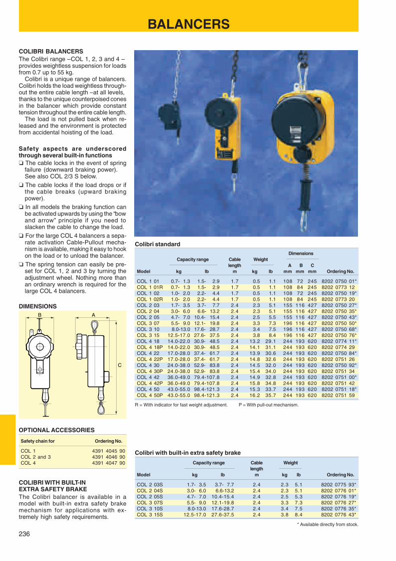
236
B A
C
BALANCERS
COLIBRI BALANCERSThe Colibri range – COL 1, 2, 3 and 4 –provides weightless suspension for loadsfrom 0.7 up to 55 kg.
Colibri is a unique range of balancers.Colibri holds the load weightless through-out the entire cable length – at all levels,thanks to the unique counterpoised conesin the balancer which provide constanttension throughout the entire cable length.
The load is not pulled back when re-leased and the environment is protectedfrom accidental hoisting of the load.
Colibri standardDimensions
Capacity range Cable Weightlength A B C
Model kg lb m kg lb mm mm mm Ordering No.
COL 1 01 0.7- 1.3 1.5- 2.9 1.7 0.5 1.1 108 72 245 8202 0750 01*COL 1 01R 0.7- 1.3 1.5- 2.9 1.7 0.5 1.1 108 84 245 8202 0773 12COL 1 02 1.0- 2.0 2.2- 4.4 1.7 0.5 1.1 108 72 245 8202 0750 19*COL 1 02R 1.0- 2.0 2.2- 4.4 1.7 0.5 1.1 108 84 245 8202 0773 20COL 2 03 1.7- 3.5 3.7- 7.7 2.4 2.3 5.1 155 116 427 8202 0750 27*COL 2 04 3.0- 6.0 6.6- 13.2 2.4 2.3 5.1 155 116 427 8202 0750 35*COL 2 05 4.7- 7.0 10.4- 15.4 2.4 2.5 5.5 155 116 427 8202 0750 43*COL 3 07 5.5- 9.0 12.1- 19.8 2.4 3.3 7.3 196 116 427 8202 0750 50*COL 3 10 8.0-13.0 17.6- 28.7 2.4 3.4 7.5 196 116 427 8202 0750 68*COL 3 15 12.5-17.0 27.6- 37.5 2.4 3.8 8.4 196 116 427 8202 0750 76*COL 4 18 14.0-22.0 30.9- 48.5 2.4 13.2 29.1 244 193 620 8202 0774 11*COL 4 18P 14.0-22.0 30.9- 48.5 2.4 14.1 31.1 244 193 620 8202 0774 29COL 4 22 17.0-28.0 37.4- 61.7 2.4 13.9 30.6 244 193 620 8202 0750 84*COL 4 22P 17.0-28.0 37.4- 61.7 2.4 14.8 32.6 244 193 620 8202 0751 26COL 4 30 24.0-38.0 52.9- 83.8 2.4 14.5 32.0 244 193 620 8202 0750 92*COL 4 30P 24.0-38.0 52.9- 83.8 2.4 15.4 34.0 244 193 620 8202 0751 34COL 4 42 36.0-49.0 79.4-107.8 2.4 14.9 32.8 244 193 620 8202 0751 00*COL 4 42P 36.0-49.0 79.4-107.8 2.4 15.8 34.8 244 193 620 8202 0751 42COL 4 50 43.0-55.0 98.4-121.3 2.4 15.3 33.7 244 193 620 8202 0751 18*COL 4 50P 43.0-55.0 98.4-121.3 2.4 16.2 35.7 244 193 620 8202 0751 59
R = With indicator for fast weight adjustment. P = With pull-out mechanism.
Colibri with built-in extra safety brake
Capacity range Cable Weightlength
Model kg lb m kg lb Ordering No.
COL 2 03S 1.7- 3.5 3.7- 7.7 2.4 2.3 5.1 8202 0775 93*COL 2 04S 3.0- 6.0 6.6-13.2 2.4 2.3 5.1 8202 0776 01*COL 2 05S 4.7- 7.0 10.4-15.4 2.4 2.5 5.3 8202 0776 19*COL 3 07S 5.5- 9.0 12.1-19.8 2.4 3.3 7.3 8202 0776 27*COL 3 10S 8.0-13.0 17.6-28.7 2.4 3.4 7.5 8202 0776 35*COL 3 15S 12.5-17.0 27.6-37.5 2.4 3.8 8.4 8202 0776 43*
OPTIONAL ACCESSORIES
Safety chain for Ordering No.
COL 1 4391 4045 90COL 2 and 3 4391 4046 90COL 4 4391 4047 90
COLIBRI WITH BUILT-INEXTRA SAFETY BRAKEThe Colibri balancer is available in amodel with built-in extra safety brakemechanism for applications with ex-tremely high safety requirements.
Safety aspects are underscoredthrough several built-in functions❏ The cable locks in the event of spring
failure (downward braking power).See also COL 2/3 S below.
❏ The cable locks if the load drops or ifthe cable breaks (upward brakingpower).
❏ In all models the braking function canbe activated upwards by using the “bowand arrow” principle if you need toslacken the cable to change the load.
❏ For the large COL 4 balancers a sepa-rate activation Cable-Pullout mecha-nism is available, making it easy to hookon the load or to unload the balancer.
❏ The spring tension can easily be pre-set for COL 1, 2 and 3 by turning theadjustment wheel. Nothing more thanan ordinary wrench is required for thelarge COL 4 balancers.
* Available directly from stock.
DIMENSIONS
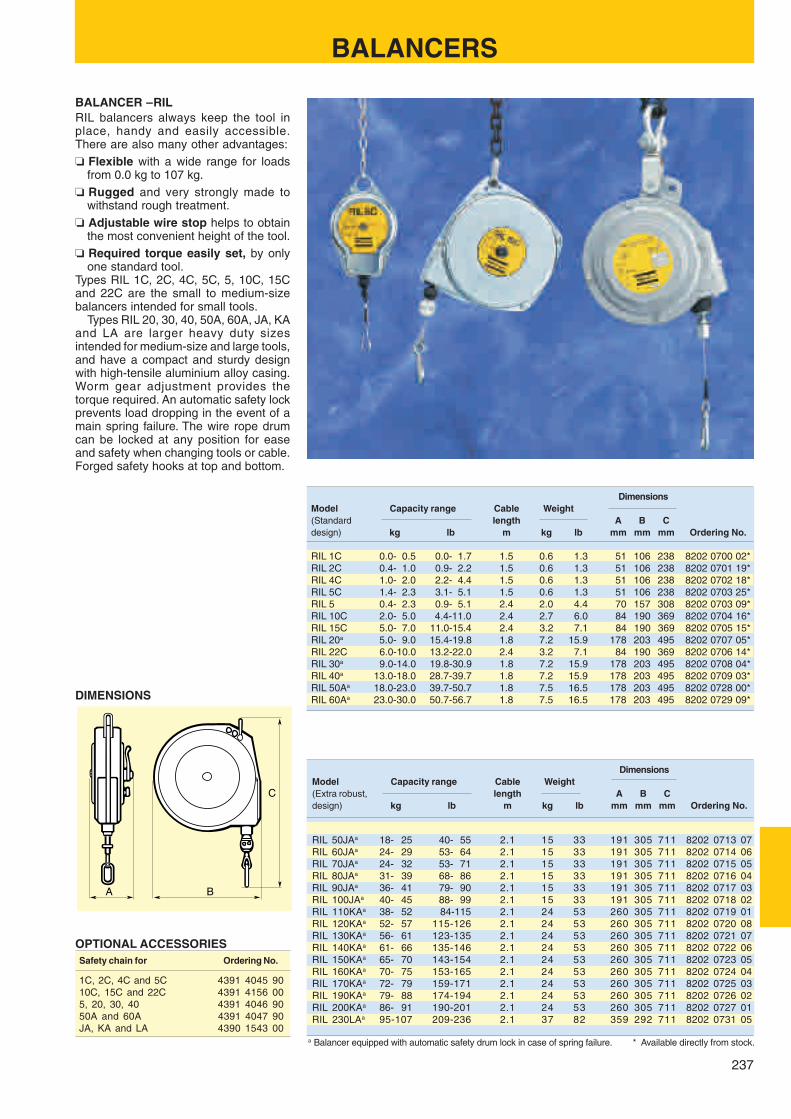
237
A B
C
BALANCER – RILRIL balancers always keep the tool inplace, handy and easily accessible.There are also many other advantages:❏ Flexible with a wide range for loads
from 0.0 kg to 107 kg.❏ Rugged and very strongly made to
withstand rough treatment.❏ Adjustable wire stop helps to obtain
the most convenient height of the tool.❏ Required torque easily set, by only
one standard tool.Types RIL 1C, 2C, 4C, 5C, 5, 10C, 15Cand 22C are the small to medium-sizebalancers intended for small tools.
Types RIL 20, 30, 40, 50A, 60A, JA, KAand LA are larger heavy duty sizesintended for medium-size and large tools,and have a compact and sturdy designwith high-tensile aluminium alloy casing.Worm gear adjustment provides thetorque required. An automatic safety lockprevents load dropping in the event of amain spring failure. The wire rope drumcan be locked at any position for easeand safety when changing tools or cable.Forged safety hooks at top and bottom.
OPTIONAL ACCESSORIESSafety chain for Ordering No.
1C, 2C, 4C and 5C 4391 4045 9010C, 15C and 22C 4391 4156 005, 20, 30, 40 4391 4046 9050A and 60A 4391 4047 90JA, KA and LA 4390 1543 00
DimensionsModel Capacity range Cable Weight(Standard length A B Cdesign) kg lb m kg lb mm mm mm Ordering No.
RIL 1C 0.0- 0.5 0.0- 1.7 1.5 0.6 1.3 51 106 238 8202 0700 02*RIL 2C 0.4- 1.0 0.9- 2.2 1.5 0.6 1.3 51 106 238 8202 0701 19*RIL 4C 1.0- 2.0 2.2- 4.4 1.5 0.6 1.3 51 106 238 8202 0702 18*RIL 5C 1.4- 2.3 3.1- 5.1 1.5 0.6 1.3 51 106 238 8202 0703 25*RIL 5 0.4- 2.3 0.9- 5.1 2.4 2.0 4.4 70 157 308 8202 0703 09*RIL 10C 2.0- 5.0 4.4-11.0 2.4 2.7 6.0 84 190 369 8202 0704 16*RIL 15C 5.0- 7.0 11.0-15.4 2.4 3.2 7.1 84 190 369 8202 0705 15*RIL 20a 5.0- 9.0 15.4-19.8 1.8 7.2 15.9 178 203 495 8202 0707 05*RIL 22C 6.0-10.0 13.2-22.0 2.4 3.2 7.1 84 190 369 8202 0706 14*RIL 30a 9.0-14.0 19.8-30.9 1.8 7.2 15.9 178 203 495 8202 0708 04*RIL 40a 13.0-18.0 28.7-39.7 1.8 7.2 15.9 178 203 495 8202 0709 03*RIL 50Aa 18.0-23.0 39.7-50.7 1.8 7.5 16.5 178 203 495 8202 0728 00*RIL 60Aa 23.0-30.0 50.7-56.7 1.8 7.5 16.5 178 203 495 8202 0729 09*
DimensionsModel Capacity range Cable Weight(Extra robust, length A B Cdesign) kg lb m kg lb mm mm mm Ordering No.
RIL 50JAa 18- 25 40- 55 2.1 15 33 191 305 711 8202 0713 07RIL 60JAa 24- 29 53- 64 2.1 15 33 191 305 711 8202 0714 06RIL 70JAa 24- 32 53- 71 2.1 15 33 191 305 711 8202 0715 05RIL 80JAa 31- 39 68- 86 2.1 15 33 191 305 711 8202 0716 04RIL 90JAa 36- 41 79- 90 2.1 15 33 191 305 711 8202 0717 03RIL 100JAa 40- 45 88- 99 2.1 15 33 191 305 711 8202 0718 02RIL 110KAa 38- 52 84-115 2.1 24 53 260 305 711 8202 0719 01RIL 120KAa 52- 57 115-126 2.1 24 53 260 305 711 8202 0720 08RIL 130KAa 56- 61 123-135 2.1 24 53 260 305 711 8202 0721 07RIL 140KAa 61- 66 135-146 2.1 24 53 260 305 711 8202 0722 06RIL 150KAa 65- 70 143-154 2.1 24 53 260 305 711 8202 0723 05RIL 160KAa 70- 75 153-165 2.1 24 53 260 305 711 8202 0724 04RIL 170KAa 72- 79 159-171 2.1 24 53 260 305 711 8202 0725 03RIL 190KAa 79- 88 174-194 2.1 24 53 260 305 711 8202 0726 02RIL 200KAa 86- 91 190-201 2.1 24 53 260 305 711 8202 0727 01RIL 230LAa 95-107 209-236 2.1 37 82 359 292 711 8202 0731 05
a Balancer equipped with automatic safety drum lock in case of spring failure.
DIMENSIONS
BALANCERS
* Available directly from stock.

238
A
C
B
HOSE REEL BALANCER – HRILThe HRIL range of hose reel balancersare specifically designed for use withsmall pneumatic hand tools.
The integrated air hose and supportcable ensures the work area is kept tidyand the tool is easy to control.❏ Ergonomics – The retraction force over
hose travel remains almost constantwhich minimizes load on the operatorand ensures smooth operation.An easily adjusted rubber stop is fittedon the hose which allows the tool to beset at the optimum position.The retraction force is easily adjustableby means of a hand wheel on the rearcasing (this can be removed if desired,once the retraction force is set).
❏ Long service life – The design fea-tures a rugged casing, self lubricatingspindle bearing bushes and a 360 de-grees rotary inlet connector.A durable hose is fitted with additionalprotection to prevent excessive bend-ing around air connectors.
❏ Low pressure drop – The HRIL bal-ancers have very good flow character-istics.
DIMENSIONS
Air line fittingsAll models have a BSP 1/4" inlet fitting.HRIL 1 supplied with M5 and BSP 1/8" outlet fittings.HRIL 3 supplied with BSP 1/8" and BSP 1/4" outlet fittings.HRIL 4 supplied with BSP 1/4" outlet fitting.
Recom- Max DimensionsCapacity range mended Hose Weight working
air flow a travel pressure A B CModel kg lb l/s m kg lb bar mm mm mm Ordering No.
HRIL 1 0.2-0.5 0.4-1.1 3.5 1.40 1.2 2.6 10 92 132 173 8202 0600 03*HRIL 3 0.5-1.4 1.1-3.1 5.5 1.40 1.2 2.6 10 92 132 173 8202 0600 11*HRIL 4 0.7-2.4 1.5-5.3 6.5 1.10 1.4 3.1 10 92 132 173 8202 0600 29*
OPTIONAL ACCESSORIES
Designation Ordering No.
Conversion kit for air inlet from below - HRIL 3, HRIL 4 4390 1687 90*
Safety chain 4391 4045 90*
HOSE REELS
Conversion kit for air inlet from below. Air inlet from above.
a At inlet pressure of 6 bar pressure drop is 0.4 bar.
* Available directly from stock.

239
220
470195
490
HOSE REEL – HMThe HoseMaster hose reel has a highquality compound hose (externally PVC,internally Polyurethane) for handling ofair and water. Movable brackets give achoice between wall, floor and ceilingmounting.
Other advantages are:❏ Safer, smooth and kink-free reeling.❏ Reduces hose wear.❏ Improves the working environment.
Max working pressure is 15 bar.Working temperature: –10 oC – +60 oC.
Hose reelHose dimensions Max
Inside dia recommended WeightLength air flowa
Model mm in m l/s kg lb Ordering No.
HM 10 10 3/8 10 12 17 37 8202 1181 40*HM 13 12.5 1/2 8 22 16 35 8202 1181 57*
a Air flow at an inlet pressure of 6 bar and a pressure drop of 0.5 bar.
OPTIONAL ACCESSORIES
Designation Ordering No.
Pivoting wall bracket, 120o 4390 1676 90*Spring for max 15 m 3/8" hose or 10 m 1/2" hose 4390 1751 00
DIMENSIONS (mm)
Do you need more information?Ask your Atlas Copco representativefor a copy of our Airline Accessories
Catalogue.
HOSE REELS
* Available directly from stock.

240
BLOW GUNS
Transparent guard Holder for suspension Star-tip nozzle – B2602 ACCESSORIES FOR GUN
Designation Ordering No.
Transparent guard 9090 1886 90*Holder for suspension 9090 1808 80*Hose nipple 9000 0241 00*Safety/Silencer nozzle 9090 1809 81*Safety nozzle 9090 1809 80*
BLOW GUN – GUNFor safer and more efficient cleaning
The Atlas Copco blow gun GUN is avail-able in different models.❏ GUN F06A – the bare blow gun.❏ GUN F06A-S – with a safety nozzle.❏ GUN F06A-SS – with a combined
safety/silencer nozzle.
The safety nozzle reduces the danger ofhigh pressure air coming into directcontact with the skin.
The safety nozzles deflect the air side-ways if the forward air flow is blocked. Inthis way they meet the U.S. OSHA stand-ard which specifies a maximum of 2 barin case of direct contact.
Blow guns – GUN, B2602
Back pressure Soundat 6 bar when Blow level Air
the nozzle is blocked force at 6 bar flow WeightModel bar N dB(A) l/s kg Ordering No.
GUN F06A-SS with safety/silencer nozzle 0.8 2 82 3.8 0.16 8202 1005 69*GUN F06A-S with safety nozzle 0.8 4 90 7.0 0.15 8202 1005 51*GUN F06A without nozzle 6 4 90 7.0 0.14 8202 1005 28*B2602 0.0 1.8 79 2.9 0.13 8202 1006 01*
* Available directly from stock.
The combined safety/silencer nozzlealso greatly reduces the noise caused bythe air current.❏ For cleaning operations.❏ Sturdy design with a light ergonomic
and convenient pistol-grip. The triggermechanism allows you to vary the airflow to suit the job you are doing.
❏ Max working pressure 10 bar.❏ Max working temperature +50oC.❏❏❏❏❏ Internal connecting thread 1/4" BSP.
BLOW GUN – B2602❏ Ultra-slim “star-tip” design that reduces
noise level.❏ The “Star-tip” nozzle reduces the dan-
ger of high pressure air coming into di-rect contact with the skin. In this wayB2602 meets the U.S. OSHA standardwhich specifies a maximum of 2 bar incase of direct contact.
❏ Bent tube reaches extremely tight areas.❏ Adjustable trigger regulates flow.❏ Handy, built-in hook for hanging.❏ Ribbed handle for better grip.❏ Brass button and inlet insert for added
strength at key stress points.❏ Internal connecting thread 1/4" BSP.

241
IP1
IP1
IP2
IP3
ErgoNIP 10 5 m PVC 10
8202 1180 18*
ERGONIP 10 0.7 m CABLAIR 10ErgoQIC 10+ ErgoNIP 10 M08
8202 1180 19*
ErgoNIP 10 5 m PVC 105 m RUBAIR 10
8202 1180 18* / 8202 1180 43*
ErgoNIP 10 0.7 m CABLAIR 100.7 m RUBAIR 10
ErgoQIC 10+ ErgoNIP 10 M08
8202 1180 19* / 8202 1180 42*
ErgoNIP 10 5 m RUBAIR 10
8202 1180 44*8202 1180 20*
ErgoNIP 10 0.7 m RUBAIR 10ErgoQIC 10+ ErgoNIP 10 M10
Optional for LSO and LST.
Choosing the correct couplings, hose and clamps can be atroublesome digging into details. To save your time and toensure correct capacity of the airline installation, from thetapping point to the tool, we offer you installation proposals foreach tool.
The installation proposals, IP, are divided into material
INSTALLATION PROPOSALSSaving you time and trouble
Material removal tools
Installation proposal for LSO / LST / LBB24 / LBS24 / LBB34 / LBB45 / LGB24 / LGB34 / LBV25 / LBV34.Filtered and regulated air for a maximum air flow of 10 l/s.
BALL VALVE +MIDI F/R 15 +ERGOQIC 108202 0845 48
Installation proposal for LSV27 / LSF27 / LSR27 / RRF21/31 / RRC13 / RRC13B / RRC13N /RRC22 / RP1 / RP3. Filtered, regulated and oil fog lubricated air for a maximum air flow of 15 l/s.
BALL VALVE +MIDI F/RD 15 +ERGOQIC 108202 0829 11
removal tools and assembly tools and they are marked withthe maximum air flow for the installation. When you havefound the installation proposal for your tool, there is only anordering number for the air preparation units, hose kit andwhip hose kit required. Ordering airline accessories for yourtools has never been easier.
This allows you to order all the parts needed for an efficient installation of the actualtool, using two or three ordering numbers.Installation proposals
Whip hose included in the 27 series.
BALL VALVE +MIDI F/RD 15 +ERGOQIC 108202 0829 11
Installation proposal for LSF17 / LSV17 / RVM07B / RRC22 / RP1 / RP3.Filtered, regulated and oil fog lubricated air for a maximum air flow of 10 l/s.
NippleMale 1/4" BSPT
NippleMale 1/4" BSPT
NippleMale 3/8" BSPT
* Available directly from stock.

242
CLAW 5 m TURBO 16
8202 1181 80*
ErgoQIC 10
CLAW 20 m TURBO 20
8202 1181 75*
ErgoQIC 10
ErgoNIP 10 5 m RUBAIR 13
8202 1180 21*
ErgoNIP 10 0.7 m RUBAIR 13ErgoQIC 10
IP4
IP6
IP8
ErgoNIP 10 5 m RUBAIR 13
8202 1180 23*8202 1180 22*
ErgoNIP 10 0.7 m RUBAIR 13ErgoQIC 10
CLAW 5 m TURBO 16
8202 1181 95*
IP7
IP5
INSTALLATION PROPOSALSMaterial removal tools
Installation proposal for RRC34 / RRC65 / RRC75 / RRD37 / RRD57.Filtered, regulated and oil fog lubricated air for a maximum air flow of 15 l/s (1/2" tool nipple).
BALL VALVE +MIDI F/RD 15 +ERGOQIC 108202 0829 11
Installation proposal for LSS53 / LSR53 / LBB36 / LSV37 / LSF36 / LSR43 / RAB9 / RAB12.Filtered, regulated and oil fog lubricated air for a maximum air flow of 31 l/s.
BALL VALVE +MIDI F/RD 15 +ERGOQIC 108202 0829 11
Installation proposal for GTG40 / GTR40 – When the inlet pressure to the F/R unit is below 6 bar.Filtered and regulated air for a maximum air flow of 60 l/s.
BALL VALVE +MAXI F/R 25 +CLAW8202 0845 55
Installation proposal for GTG40 / GTR40 – When the inlet pressu re to the F/R unit is below 6 bar.Filtered and regulated air for a maximum air flow of 60 l/s.
BALL VALVE +MAXI F/R 25 +CLAW8202 0845 55
BALL VALVE +MAXI F/R 25 +CLAW8202 0845 55
Installation proposal for GTG40 / GTR40 – When the inlet pressu re to the F/R unit is below 6 bar.Filtered and regulated air for a maximum air flow of 60 l/s.
Whip hose for LSS53, LSR53 and LSR43.Whip hose included in LSV37.
Nipple is includedwith the tool.
Whip hose included in the 40 series.
Whip hose included in the 40 series.
NippleMale 1/2" BSPT
NippleMale 1/2" BSPT
* Available directly from stock.
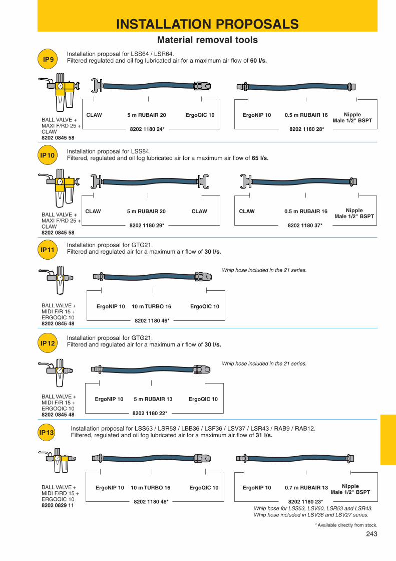
243
ErgoNIP 10 5 m RUBAIR 13
8202 1180 22*
ErgoQIC 10
IP10
ErgoNIP 10 10 m TURBO 16
8202 1180 46*
ErgoQIC 10
IP11
IP12
ErgoNIP 10 10 m TURBO 16
8202 1180 23*8202 1180 46*
ErgoNIP 10 0.7 m RUBAIR 13ErgoQIC 10
CLAWCLAW 5 m RUBAIR 20
8202 1180 37*8202 1180 29*
0.5 m RUBAIR 16CLAW
CLAW 5 m RUBAIR 20
8202 1180 28*8202 1180 24*
ErgoNIP 10 0.5 m RUBAIR 16ErgoQIC 10
IP13
IP9
BALL VALVE +MAXI F/RD 25 +CLAW8202 0845 58
Installation proposal for LSS64 / LSR64.Filtered regulated and oil fog lubricated air for a maximum air flow of 60 l/s.
BALL VALVE +MAXI F/RD 25 +CLAW8202 0845 58
Installation proposal for LSS84.Filtered, regulated and oil fog lubricated air for a maximum air flow of 65 l/s.
BALL VALVE +MIDI F/R 15 +ERGOQIC 108202 0845 48
Installation proposal for GTG21.Filtered and regulated air for a maximum air flow of 30 l/s.
BALL VALVE +MIDI F/R 15 +ERGOQIC 108202 0845 48
Installation proposal for GTG21.Filtered and regulated air for a maximum air flow of 30 l/s.
Installation proposal for LSS53 / LSR53 / LBB36 / LSF36 / LSV37 / LSR43 / RAB9 / RAB12.Filtered, regulated and oil fog lubricated air for a maximum air flow of 31 l/s.
BALL VALVE +MIDI F/RD 15 +ERGOQIC 108202 0829 11
INSTALLATION PROPOSALSMaterial removal tools
Whip hose included in the 21 series.
Whip hose included in the 21 series.
Whip hose for LSS53, LSV50, LSR53 and LSR43.Whip hose included in LSV36 and LSV27 series.
NippleMale 1/2" BSPT
NippleMale 1/2" BSPT
NippleMale 1/2" BSPT
* Available directly from stock.

244
IP21A
IP22
IP23
IP21
IP22A
8202 1180 67*
ErgoNIP 10 5 m CABLAIR 06 ErgoQIC 08
ErgoNIP 08 5 m CABLAIR 06 ErgoQIC 08
8202 1182 01*
ErgoNIP 10 5 m CABLAIR 08 ErgoQIC 08
8202 1180 77*
ErgoNIP 08 5 m CABLAIR 08 ErgoQIC 08
8202 1182 02*
ErgoNIP 10 5 m PVC 10 ErgoQIC 08
8202 1180 30*
INSTALLATION PROPOSALS Assembly tools
Installation proposal for LUM10 / LUM12 / LUM21 / LUF10 / LUF20 / LTV08.Filtered and regulated air for a maximum air flow of 5 l/s.
BALL VALVE +MIDI F/R 15 +ERGOQIC 108202 0845 48
Installation proposal for EP5 / EP6 / EP8 / EP10 / LUM25 / TWIST / LMS06 / LTV08 / LTV18.Filtered and regulated air for a maximum air flow of 8 l/s.
BALL VALVE +MIDI F/R 15 +ERGOQIC 108202 0845 48
Installation proposal for EP7 / EP8 / EP10 / EP12 PT / EP12 XS / LUF34 / LMP24.Filtered and regulated air for a maximum air flow of 14 l/s.
BALL VALVE +MIDI F/R 15 +ERGOQIC 108202 0845 48
ErgoNIP 08Male 1/8" BSP
ErgoNIP 08Male 1/4" BSP
ErgoNIP 08Male 1/4" BSP
Installation proposal for LUM10 / LUM12 / LUM21 / LUF10 / LUF20 / LTV08.Filtered and regulated air for a maximum air flow of 5 l/s.
BALL VALVE +MIDI F/R 15 +ERGOQIC 088202 0845 49
ErgoNIP 08Male 1/8" BSP
Installation proposal for EP5 / EP6 / EP8 / EP10 / LUM25 / TWIST / LMS06 / LTV08 / LTV18.Filtered and regulated air for a maximum air flow of 8 l/s.
BALL VALVE +MIDI F/R 15 +ERGOQIC 088202 0845 49
ErgoNIP 08Male 1/4" BSP
* Available directly from stock.

245
IP25
IP24
IP23A
IP24A
IP25A
ErgoNIP 08 5 m PVC 10 ErgoQIC 08
8202 1182 03*
ErgoNIP 10 5 m PVC 10 ErgoQIC 08
8202 1180 31*
ErgoNIP 08 5 m PVC 10 ErgoQIC 08
8202 1182 04*
ErgoNIP 10 5 m PVC 10 ErgoQIC 08 + ErgoNIP 08 M08
8202 1180 30* 8202 1180 47*
ErgoNIP 08 0.7 m PVC 10
ErgoNIP 08 5 m PVC 10 ErgoQIC 08 + ErgoNIP 08 M08
8202 1182 03* 8202 1180 47*
ErgoNIP 08 0.7 m PVC 10
INSTALLATION PROPOSALS Assembly tools
Installation proposal for EP14 XS.Filtered and regulated air for a maximum air flow of 14 l/s.
BALL VALVE +MIDI F/R 15 +ERGOQIC 108202 0845 48
Installation proposal for LTS17 / LTS27 / LTS37 / LTS57.Filtered, regulated and oil fog lubricated air for a maximum air flow of 14 l/s.
BALL VALVE +MIDI F/RD 15 +ERGOQIC 108202 0829 11
ErgoNIP 08Male 3/8" BSP
NippleMale 1/4" BSPT
Installation proposal for EP7 / EP8 / EP10 / EP12 PT / EP12 XS / LUF34 / LMP24.Filtered and regulated air for a maximum air flow of 14 l/s.
BALL VALVE +MIDI F/R 15 +ERGOQIC 088202 0845 49
ErgoNIP 08Male 1/4" BSP
Installation proposal for EP14 XS.Filtered and regulated air for a maximum air flow of 14 l/s.
BALL VALVE +MIDI F/R 15 +ERGOQIC 088202 0845 49
ErgoNIP 08Male 3/8" BSP
Installation proposal for LTS17 / LTS27 / LTS37 / LTS57.Filtered, regulated and oil fog lubricated air for a maximum air flow of 14 l/s.
BALL VALVE +MIDI F/RD 15 +ERGOQIC 088202 0829 13
NippleMale 1/4" BSPT
* Available directly from stock.

246
7.6 m CABLAIR 10
8202 1180 38
IP29
IP28
5 m RUBAIR 13
8202 1180 21*
ErgoQIC 10 ErgoNIP 10 0.7 m RUBAIR 13ErgoNIP 10
IP27
IP26
IP26A
ErgoNIP 10 5 m PVC 10 ErgoQIC 08 + ErgoNIP 08 M08
8202 1180 30* 8202 1180 50*
ErgoNIP 08 0.7 m PVC 10
ErgoNIP 08 5 m PVC 10 ErgoQIC 08 + ErgoNIP 08 M08
8202 1182 03* 8202 1180 50*
ErgoNIP 08 0.7 m PVC 10
5 m RUBAIR 16
8202 1180 32*
ErgoQIC 10 ErgoNIP 10 0.7 m RUBAIR 16ErgoNIP 10
INSTALLATION PROPOSALS Assembly tools
Installation proposal for LTV28.Filtered, regulated and injection lubricated air for a maximum air flow of 10 l/s.
BALL VALVE +MIDI F/R 15 +DOS 15B8202 0845 66
Nipple 3/8" BSPT+Bushing 1/2" – 3/8"
Nipple 1/4" BSPT
Installation proposal for LMS17 / LMS27.Filtered, regulated and oil fog lubricated air for a maximum air flow of 14 l/s.
BALL VALVE +MIDI F/RD 15 +ERGOQIC 108202 0829 11
Installation proposal for LMS37 / LMS47 / LMS57 / LMS61 / LMS64.Filtered, regulated and oil fog lubricated air for a maximum air flow of 22 l/s.
BALL VALVE +MIDI F/RD 15 +ERGOQIC 108202 0829 11
Installation proposal for LMS86.Filtered, regulated and oil fog lubricated air for a maximum air flow of 30 l/s.
BALL VALVE +MIDI F/RD 15 +ERGOQIC 15B8202 0829 11
NippleMale 3/8" BSPT
Nipple is included with
the tool
Nipple is included with
the tool
Installation proposal for LMS17 / LMS27.Filtered, regulated and oil fog lubricated air for a maximum air flow of 14 l/s.
BALL VALVE +MIDI F/RD 15 +ERGOQIC 088202 0829 13
NippleMale 3/8" BSPT
* Available directly from stock.

247
7.6 m CABLAIR 13
8202 1180 39*
IP33
IP34
ErgoQIC 08 ErgoNIP 10
8202 1180 78*
5 m CABLAIR 10
ErgoQIC 08 ErgoNIP 10
8202 1180 79*
5 m CABLAIR 13
7.6 m CABLAIR 16
8202 1180 40
IP30
IP31
Installation proposal for EP8 / EP10 / EP12.Filtered and regulated air for a maximum air flow of 14 l/s.
BALL VALVE +MIDI F/R 15 +ERGOQIC 108202 0845 48
Installation proposal for EP12 PTS / EP14 / EP16 / EP20.Filtered and regulated air for a maximum air flow of 22 l/s.
BALL VALVE +MIDI F/R 15 +ERGOQIC 108202 0845 48
ErgoNIP 08Male 1/4" BSP
ErgoNIP 08Male 3/8" BSP
Installation proposal for LMP51 / LTV38.Filtered, regulated and injection lubricated air for a maximum air flow of 19 l/s.
BALL VALVE +MIDI F/R 15 +DOS 15B8202 0845 66
Installation proposal for LTV46 / LTV48.Filtered, regulated and injection lubricated air for a maximum air flow of 30 l/s.
BALL VALVE +MIDI F/R 15 +DOS 15B8202 0845 66
Nipple male 3/8" BSPT+Reduction 3/8" – 1/4" BSP
Nipple 1/2" BSPT
Nipple male1/2" BSPT
Nipple 1/2" BSPT
INSTALLATION PROPOSALS Assembly tools
* Available directly from stock.

248
PRESSURE CONTROL UNITThe unit consists of a quality pressure gauge and the necessarycouplings for checking the air pressure at the air inlet of themachine.Ordering No. 4145 0699 81*.
AIR TOOL SIMULATORIn order to check whether the pressure or the flow is sufficientthe air tool simulator can be connected instead of the tool. Thesimulator is delivered with different connections.Ordering No. 4145 0698 81*.
TEST EQUIPMENT
* Available directly from stock.
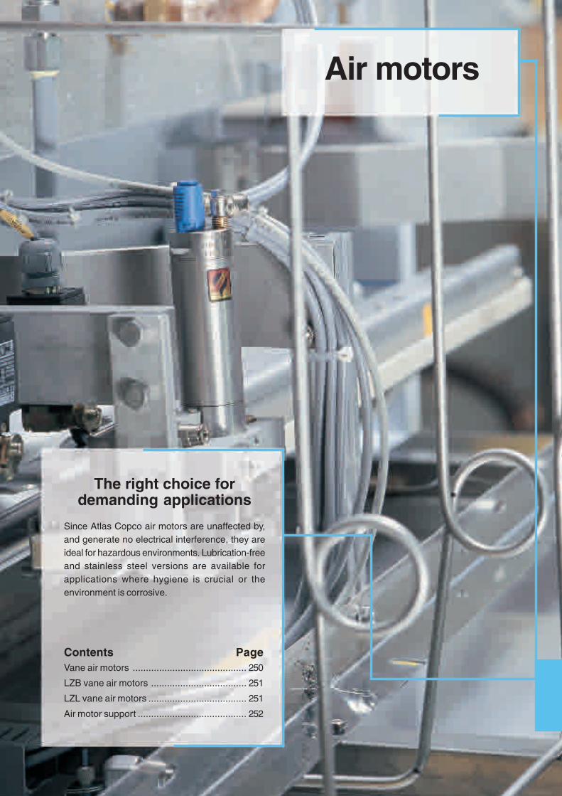
Air motors
The right choice fordemanding applications
Since Atlas Copco air motors are unaffected by,and generate no electrical interference, they areideal for hazardous environments. Lubrication-freeand stainless steel versions are available forapplications where hygiene is crucial or theenvironment is corrosive.
Contents PageVane air motors ........................................... 250
LZB vane air motors .................................... 251
LZL vane air motors ..................................... 251
Air motor support ......................................... 252

250
VANE AIR MOTORS
Air motors from Atlas Copco – the reli-able, cost-effective solution when apply-ing power to rotating machines. Considerthe air motor features and characteristicsgiving large benefits to the designer.
❏ Power-to-weight performance that issuperior to most other motors, in fact,75% lighter and 85% smaller than anasynchronous electric motor with thesame output.
❏ Can be held stalled at full torque in-definitely, and accepts repeatedstarting and stopping without limitation.
❏ Torque, speed and direction of rotationcan be changed easily using simplecontrol methods.
❏ Output that automatically adjusts tomatch the applied load.
❏ Controllable over a wide speed range.❏ Ideal for many applications in hazard-
ous or hostile environments.❏ Smooth start-up to minimize “shock”
loading on transmission components.❏ Unaffected by, and will not generate,
electrical interference.
Customized air motors to your individual specificationsWhatever the requirement, Atlas Copco is always happy to help customers find solutions to their special needs.For OEMs, for instance, a customized air motor can be the most efficient solution when integrating an air motorinto a machine or a tool. Special motors may have unique casings or mounting arrangements. They may utilizenon-standard materials or surface coatings and be designed to achieve a specific output.
Unique features for LZB motors
Lubrication-free air motors forsensitive processes where hygienicoperation is crucialEquipped with low friction vanes andsealed bearings the lubrication-free mo-tors release no lubricants into the air.They offer a viable drive solution for sen-sitive processes and hygienic environ-ments where oil contamination would beat best a problem and, at worst, a catas-trophe.
Stainless steel air motors for harshand aggressive environmentsThe stainless steel air motors are idealfor harsh or even aggressive environ-ments where hygiene is essential. Theyhave a “clean” design with no pocketswhere dirt can collect. They are fitted withdouble shaft seals to prevent water fromentering the gears. Lubrication-freeversions are also available.
High torque air motors when a realworkhorse is neededFitted with extra strong planetary gears thehigh torque air motors provide torquesup to 680 Nm. The gears are dimensionedto stand being loaded at full stall torqueindefinitely. Despite their strength thehigh torque air motors are compactcompared to solutions with helical orworm gears. Lubrication-free versions arealso available.

251
LZB AND LZL VANE AIR MOTORS
0.1 – 1.2 kWThe LZB vane air motors are compact indesign, light in weight and available in ahost of different gear ratios to meet a va-riety of speed requirements. They areparticularly suited to be built into handheld machines and also many differenttypes of industrial equipment.
The LZB14, LZB22 and LZB33 models are available in lubrication-free versions. LZB14, LZB22 and LZB33 can be obtained in a stainless steelversion. The standard non-reversible motors have clockwise rotation but can also be obtained with anti-clockwise rotation.
MotorMax output Speed at Torque at max output Min start torque Free No. of diameter
max output speed gearModel kW hp r/min Nm ft lb Nm ft lb r/min ratios mm inNon-reversibleLZB14 0.16 0.22 330 - 9100 0.17 - 4.7 0.12 - 3.4 0.26 - 7 0.19 - 5.1 690 - 19500 5 27 1.1LZB22 0.25 0.34 235 - 9600 0.25 - 9.9 0.18 - 7.3 0.45 - 17 0.33 -12.5 510 - 21500 7 36 1.4LZB33 0.39 0.52 10 - 9400 0.40 - 340 0.30 - 251 0.76 - 680 0.56 - 501 21 - 20000 17 42 1.6LZB42 0.65 0.87 25 -10500 0.59 - 236 0.44 - 174 1.10 - 430 0.80 - 315 50 - 21000 12 46 1.8LZB46 0.84 1.13 25 -10800 0.74 - 300 0.55 - 220 1.20 - 490 0.88 - 360 50 - 21000 12 46 1.8LZB54 1.20 1.60 65 - 9300 1.20 - 175 0.88 - 129 1.80 - 250 1.30 - 180 125 - 18000 10 60 2.4ReversibleLZB14 0.10 0.14 230 - 6500 0.15 - 4.1 0.11 - 3.0 0.19 - 5 0.14 - 3.7 460 - 13000 5 27 1.1LZB22 0.16 0.22 5 - 6500 0.24 -10.8 0.18 - 8 0.35 -13.4 0.26 - 9.9 5 - 13800 9 36 1.4LZB33 0.24 0.32 7 - 7000 0.34 - 305 0.25 - 225 0.46 - 412 0.34 - 304 5 - 14000 21 42 1.6LZB42 0.53 0.71 19 - 8100 0.62 - 250 0.46 - 184 0.70 - 270 0.52 - 200 37 - 16000 12 46 1.8LZB46 0.62 0.83 20 - 8600 0.68 - 275 0.50 - 200 0.75 - 300 0.55 - 220 40 - 17000 12 46 1.8LZB54 0.82 1.10 45 - 6800 1.20 - 165 0.88 - 122 1.20 - 165 0.88 - 122 90 - 13000 10 60 2.4
For more information on Atlas Copco vane motors see our air motor catalogue, Ordering No. 9833 8998 01.
Max output Speed at Torque at max output Min start torque Free No. ofmax output speed gear
Model kW hp r/min Nm ft lb Nm ft lb r/min ratios
Motor onlyLZL05 1.6 2.1 4670 3.2 2.4 5.3 3.9 9300 –LZL15 2.6 3.5 3380 7.3 5.4 12.2 9.0 7100 –LZL25 3.7 5.0 2800 12.7 9.4 20.8 15.3 5900 –LZL35 5.2 7.0 2380 20.5 15.1 32.0 23.6 4800 –With helical gear unitLZL05 1.6 2.1 19 - 495 28 - 730 20 - 538 40 - 1090 30 - 804 37 - 990 11LZL15 2.6 3.5 17 - 375 62 -1360 46 -1000 105 - 2330 78 - 1720 35 - 785 11LZL25 3.7 5.0 14 - 305 112 -2430 82 -1800 185 - 4050 138 - 3000 29 - 635 11LZL35 5.2 7.0 18 - 470 100 -2540 75 -1870 160 - 4110 120 - 3035 37 - 950 9With worm gear unitLZL05 1.2 1.6 65 - 515 22 - 140 16 - 100 – – 125 - 1020 7LZL15 2.2 3.0 54 - 395 54 - 325 40 - 240 – – 110 - 840 7LZL25 3.4 4.6 43 - 350 91 - 624 67 - 460 – – 85 - 730 7
1.6 – 5.2 kWThe LZL vane motors are reversible airmotors which have been designed to offeroutstanding starting and low speed per-formance. These general purpose motorsare powerful, durable and offer longservice life.

252
AIR MOTOR SUPPORT
Customized air motors to your individual specificationsWhatever the requirement, Atlas Copco is always happy tohelp customers find solutions to their special needs. For OEMs,for instance, a customized air motor can be the most efficientsolution when integrating an air motor into a machine or tool.
Special motors may have unique casings or mounting arrange-ments. They may utilize non-standard materials or surfacecoatings and be designed to achieve a specific output.
Air motor drawing libraryCAD-drawings of any of the hundreds of different Atlas Copcoair motors are available to designers on CD or to download fromInternet (in both .DXF and .IGS formats) from the Atlas Copco AirMotor Draw Library. These CAD-drawings can then be quicklyand easily inserted into the designer's machine drawing.Ordering No. 9833 1139 00
Select your air motor in 30 seconds!Designed for Windows-based PCs, Atlas Copco has developedan Air Motor Selection Guide. It stores data on all of Atlas Copco'sair motors.
The designer specifies the required torques and speed of themotor and within seconds the program chooses the optimummotor. It also supplies complete documentation with perform-ance curves and motor data.Ordering No. 9833 9093 00
When more information is requiredFor further information on Atlas Copco vane motors please ask for acopy of our Air Motor catalogue, Ordering No. 9833 8998 01.
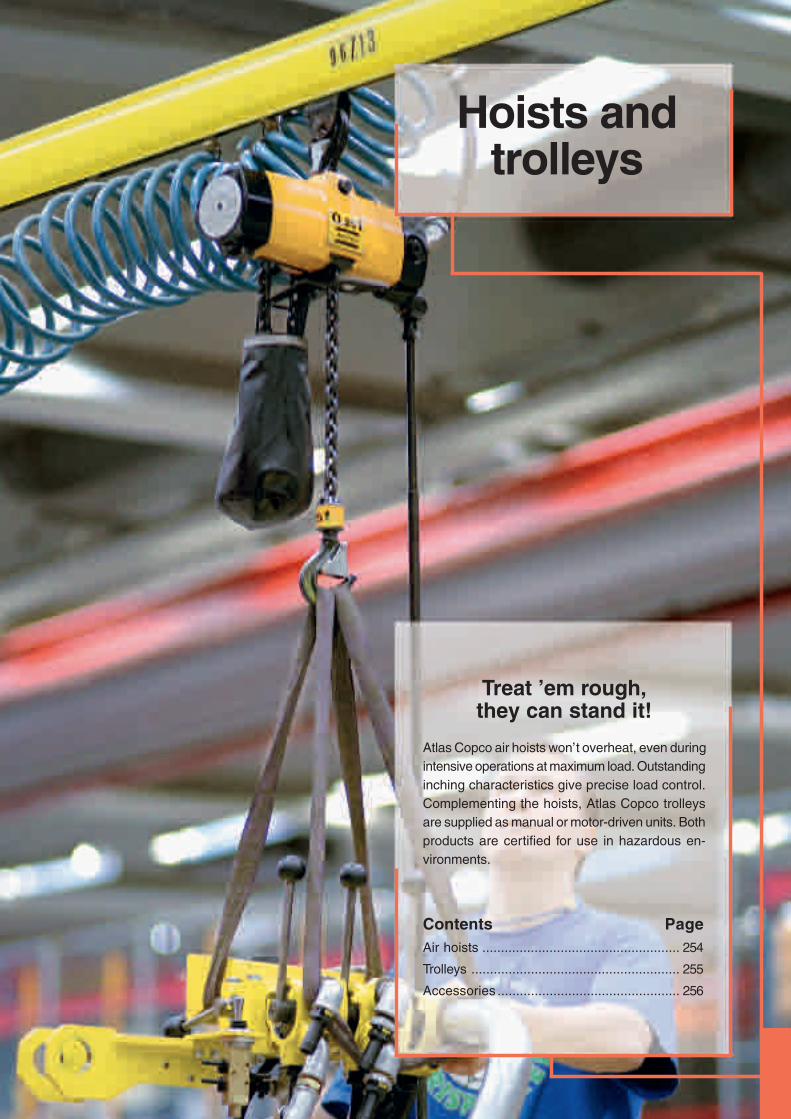
253
Hoists andtrolleys
Treat ’em rough,they can stand it!
Atlas Copco air hoists won’t overheat, even duringintensive operations at maximum load. Outstandinginching characteristics give precise load control.Complementing the hoists, Atlas Copco trolleysare supplied as manual or motor-driven units. Bothproducts are certified for use in hazardous en-vironments.
Contents PageAir hoists ..................................................... 254
Trolleys ........................................................ 255
Accessories ................................................. 256

254
DIMENSIONS
ACCESSORIES INCLUDEDWooden handle for pull chain hose nippleBSP 1/2"
Suspension hook and load hook
OPTIONAL ACCESSORIESPage 256
AIR HOISTS
Explosion proof for safe operationOur air hoists and trolleys are ideal for liftapplications in hazardous environments,where sparks or high outer temperaturescould ignite explosive gases, vapour ordust. All are certified Explosion-proof, tostringent European standards, in com-pliance with the EU ATEX Directive. Avail-able in six sizes, they offer lift capacitiesfrom 200 kg to 5 tons. All hoists andtrolleys are certified to level Ex II 2G T5 IIB D100°C. The SR types are even certi-fied to Ex II 2G T5 IIC D100°C.❏ Precise and stepless speed control
– Through effective stepless controlwith excellent creep characteristics theLLA air hoists are fast to use over theentire speed range.
❏ Heavy duty performance – These airhoists can continually operate at maxi-mum load with frequent start and stopcycles without risk of damage.
❏ Elimination of load sink – The patentedbrake mechanism eliminates loadsinkwhen starting lifting, and automaticallyholds the load if the air supply fails.
❏ Compact size – The small dimensionsmake the LLA hoists easy to install,even in the most restricted space. Alsothe low weight means the hoists caneasily be moved for maintenance orrelocation purposes.
Max lifting Lifting speed Weight Chain Air con- Hosecapacity at full load Chain excl chain weight Required Sound sumption Hose dia fitting
strands chain-length level threadModel kg ton m/min ft/min qty kg lb kg/m lb/ft metre dB(A) l/s cfm mm in BSP Ordering No.
LLA200 EX 200 0.2 20.2 66.3 1 12.7 28.0 0.9 0.6 Lifting height + 0.5 84 38 81 12.5 1/2 1/2 8451 1540 02*LLA250 EX 250 0.25 18.6 61.0 1 12.7 28.0 0.9 0.6 Lifting height + 0.5 84 37 78 12.5 1/2 1/2 8451 1540 10*LLA500 EX 500 0.5 12.6 41.3 1 12.7 28.0 0.9 0.6 Lifting height + 0.5 83 38 81 12.5 1/2 1/2 8451 1540 28*LLA1000 U EXa 1000 1.0 6.3 20.7 2 14.5 32.0 0.9 0.6 2 x lifting height + 0.5 83 38 81 12.5 1/2 1/2 8451 1540 69*LLA1000 EXb 1000 1.0 6.3 20.7 2 14.5 32.0 0.9 0.6 2 x lifting height + 0.5 83 38 81 12.5 1/2 1/2 8451 1540 36*LLA2500 EXb 2500 2.5 3.2 10.5 1 42.5 93.7 2.9 1.9 Lifting height + 0.6 79 40 85 20.0 3/4 1/2 8451 1540 44*LLA5000 EXb 5000 5.0 1.6 5.2 2 65.5 144.4 2.9 1.9 2 x lifting height + 0.9 79 40 85 20.0 3/4 1/2 8451 1540 51*
Spark-resistant modelLLA250-SR 250 0.25 17.0 55.8 1 12.7 28.0 0.9 0.6 Lifting height + 0.5 83 45 95 12.5 1/2 1/2 8451 1510 08LLA500-SR 500 0.5 8.5 27.9 2 14.5 32.0 0.9 0.6 2 x lifting height + 0.5 83 45 95 12.5 1/2 1/2 8451 1510 16LLA1250-SR 1250 1.25 5.0 16.4 1 42.5 93.7 2.9 1.9 Lifting height + 0.6 79 50 106 20.0 3/4 1/2 8451 1510 24
a Without overload protection device, not to be used within the European Community.b Overload protection device included as standard.
NOTE: The load chain and pull chain must be ordered separately.
* Available directly from stock.
A B C DModel mm in mm in mm in mm in
LLA200 / 250 EX 377 14.8 122 4.8 390 15.4 29 1.1LLA500 EX / 250-SR 377 14.8 122 4.8 390 15.4 29 1.1LLA1000 U EX / 500-SR 445 17.5 122 4.8 390 15.4 29 1.1LLA1000 EX 495 19.4 122 4.8 390 15.4 29 1.1LLA2500 EX / 1250-SR 575 22.6 212 8.3 546 21.5 50 2.0LLA5000 EX 785 30.9 249 9.8 546 21.5 60 2.4

255
C
B
A D
EF
Max Max speed Air Beam width Beam width Curvecapacity with full load consumption standard optional radius min Weight
Model kg ton m/min ft/min l/s cfm mm in mm in mm in kg lb Ordering No.
ManualTLT1000 1000 1 – – – – 50-165 2 - 6.5 134-265 5.3-10.4 1250 50 9.4 21 8451 1520 06TLT2500 2500 2.5 – – – – 136-334 5.2-13.1 60-172 2.3- 6.7 2200 88 32.0 70 8451 1520 55LLT1000-SR 1000 1 – – – – 54-173 2.1- 6.8 140-273 5.5-10.7 1200 47 9.5 21 8451 1500 00LLT2500-SR 2500 2.5 – – – – 133-332 5.2-13.1 58-170 2.3- 6.7 1400 55 24.5 54 8451 1500 26
Motor-drivenTLT1000Ma 1000 1 14.0 45.9 4.0 8.5 50-155 2 - 6.1 134-255 5.3-10.0 1250 50 11.0 24 8451 1520 14LLT2500Mb 2500 2.5 17.8 58.4 42.0 89.0 133-306 5.2-12.0 58-144 2.4- 5.7 1400 55 41.0 90 8451 1491 19LLT5000Mb 5000 5 16.2 53.1 42.0 89.0 145-300 5.7-11.8 70-148 2.8- 5.8 1800 71 91.0 200 8451 1491 27LLT1000(M)-SRac 1000 1 14.0 45.9 4.5 9.5 54-153 2.1- 6.0 140-253 5.5-10.0 1200 47 11.0 24 8451 1500 42LLT2500M-SRbc 2500 2.5 17.8 58.4 42.0 89.0 133-306 5.2-12.0 58-144 2.3- 5.7 1400 55 41.0 90 8451 1500 34
Sound level: TLT1000M and LLT1000(M) = 85 dBLLT2500M and LLT5000M = 81 dB
Performance figures are at 6 bar working pressure.
Motor-driven trolleys have 1/2" BSP air connection.
12.5 mm (1/2") hose size recommended for LLT1000M,20 mm for LLT2500M and 5000M.
a Pendant control must be ordered separately.b Includes handle for control chain. Control chain
must be ordered separately.c The pendant controls are not spark resistant.
DIMENSIONSC C
A B standard (opt) D E F
Model mm in mm in mm in mm in mm in mm in mm in
ManualTLT1000 22.0 0.9 52 2.0 212 8.3 312 12.2 – – 264 10.4 – –TLT2500 37.0 1.5 75 2.9 400 15.7 238 9.4 – – 370 12.8 – –LLT1000-SR 23.5 0.9 55 2.2 212 8.3 312 12.3 – – 250 9.8 – –TLT2500-SR 37.0 1.5 57 2.2 400 15.7 238 9.4 – – 364 14.3 – –
Motor-drivenTLT1000M 22.0 0.9 52 2.0 212 8.3 312 12.2 224 8.8 264 10.4 – –LLT1000(M)/-SR 23.5 0.9 55 2.2 212 8.3 312 12.3 225 8.9 250 9.8 – –LLT2500M/-SR 39.0 1.5 82 3.2 400 15.7 238 9.4 161 6.3 364 12.8 126 5.0LLT5000M 61.0 2.4 118 4.6 424 16.7 282 11.1 181 7.1 422 16.6 79 3.1
ACCESSORIES INCLUDEDLLT2500M/5000M Wooden handle for pullchain
OPTIONAL ACCESSORIESPage 256
Atlas Copco trolleys are available in 3sizes, for maximum loads of 1, 2.5 and 5tonnes. All models can be offered with airmotor drive. The 1 tonne trolley includesmotor without pedant control. The 2.5 and5 tonne includes handle for control chain(control chain must be ordered separ-ately). The 1 and 2.5 tonne trolleys arealso available in manual versions.
Simple installationThe trolleys are easy to install. The wheelsare designed so that the trolley is equallysuitable on both parallel and taperedI-beam section beams. The distance be-tween the wheels is easily adjusted tosuit the beam width by turning the sus-pension yoke.
TROLLEYS
NOTE: Suspension yoke for optional beam widthmust be ordered separately. See page 256.

256
OPTIONAL ACCESSORIES. Hoists
Ordering No. Ordering No. Ordering No. Ordering No.Designation LLA200/250/500/1000 EX LLA2500/5000 EX LLA250/500-SR LLA1250-SR
Load chain, zinc plated, per m 4310 2293 00 4310 2296 00Load chain, stainless steel, per m 4310 2211 00 4310 2219 00Control chain, zinc plated, per m 4310 0748 00 4310 0748 00Control chain, stainless steel, per m 4310 2221 00 4310 2221 00
2 button pendant controlHandle and actuators only 4310 2261 90 4310 2262 90 4310 2261 90 4310 2262 90Hose set per m 4380 0576 91 4380 0576 91 4380 0576 91 4380 0576 91
4 button pendant controlHandle and actuators only 4310 2263 90 4310 2264 90 4310 2263 90 4310 2264 90Hose set per m 4380 0576 94 4380 0576 93 4380 0576 94 4380 0576 93
Twist rod controlComplete (1.1-2.0 m) 4310 0774 91 4310 0774 91 4310 0774 91 4310 0774 91Extension set (1.1-1.9 m) 4310 0780 91 4310 0780 91 4310 0780 91 4310 0780 91Articulating link 4310 0876 91 4310 0876 91 4310 0876 91 4310 0876 91
Chain collectors PVC for length of chain – 4 m 4310 0742 04 4310 0742 04– 7 m 4310 0742 07 4310 2291 07 4310 0742 07 4310 2291 07–12 m 4310 0742 12 4310 0742 12–18 m 4310 0742 18 4310 0742 18–25 m 4310 0742 25 4310 0742 25
Chain collectors Steel for length of chain –12 m 4310 2102 80 4310 2102 80–18 m 4310 2109 80 4310 2109 80
Overload protection deviceLLA200 EX / 250 EX / 250-SR 4310 0812 83 4310 2233 90LLA500 EX / 500-SR 4310 0812 84 4310 2233 91LLA1000 U EX 4310 0812 85LLA1000 EX / 1250-SR / 2500 EX / 5000 EX incl as standard incl as standard incl as standard
Safety hooks, zinc plated 4310 0739 01Chain stop, zinc plated 4310 0740 91 4310 2097 91Chain stop, stainless steel 4310 2231 90 4310 2232 90
NOTE: For items specified per metre, the required length should be indicated by multiplying the Ordering No. by the required length, ie. to order 12 m of chain for anLLA250-SR the order should be 12 x 4310 2211 00.
When ordering load chain, follow the recommendations on chain given in the technical data for LLA hoists.
OPTIONAL ACCESSORIES. Trolleys
Ordering No. Ordering No. Ordering No. Ordering No. Ordering No.Designation TLT1000/LLT1000-SR LLT2500/-SR TLT1000M/LLT1000(M)-SR LLT2500M/M-SR LLT5000M
Suspension yoke 4380 0640 02 4380 0608 00 4380 0640 02 4380 0608 00 4380 0628 00
Zinc plated control chain per m 4310 0748 00 4310 0748 00
Stainless steel control chain per m 4310 2221 00
2 button pendant controlHandle and actuator only 4310 0835 91 4310 2262 90 4310 2262 90
Hose kit per m 4380 0576 92 4380 0576 91 4380 0576 91
ACCESSORIES FOR HOISTS AND TROLLEYS
Air hoist selection programThe fastest way to choose correct hoistsand accessories is by using theWindows based computer programavailable on CD-rom.Ordering No. 9833 1087 00
EXAMPLE: To order a 500 kg hoist with motor driven trolley, four buttonfive-metre long pendant control and a load chain fora ten-metre lift, send the following:
Order to be sent Comments
1 x 8451 1540 28 LLA500 EX Hoist block
11 x 4310 2293 00 Load chain for hoist = Required height of lift
+ 0.5 m, (see technical data for LLA Hoists)
1 x 8451 1520 14 TLT1000M Motor driven trolley
1 x 4310 2263 90 4 button handle + hoist actuator
5 x 4380 0576 94 Hose set for 4 button pendant control
1 x 8990 0001 00 Instruction to assemble above items
To order your hoist or trolley with accessories factory fitted,simply list all items required and add theOrdering No. 8990 0001 00, to order.

Rec
ycla
ble
pap
er. P
rin
ted
in S
wed
en. S
tro
kirk
-Lan
dst
röm
s, L
idkö
pin
g 2
003:
1S
ub
ject
to
alt
erat
ion
wit
ho
ut
pri
or
no
tice
.98
37 3
000
01
In
du
st
ria
l P
ow
er
T
oo
ls
2
00
4
www.atlascopco.com
Industrial Power Tools