Embed Size (px)
Citation preview

Industrial Modem RF115RS-485 RF Modem Modules
Optional RF Antennas
APRIL 2003MDR151-0050-R2MDR151-0100-R2MDR152-0025-R3MDR152-0050-R3MDR152-0100-R3
MDR153MDR154
MDR100A-R4MDR100AE-R4MDR100AE-AUS-R4MD3310-R2MD3311-R2MDR151-0010-R2MDR151-0025-R2
CUSTOMERSUPPORT
INFORMATION
Order toll-free in the U.S. 24 hours, 7 A.M. Monday to midnight Friday: 877-877-BBOXFREE technical support, 24 hurs a day, 7 days a week: Call 724-746-5500 or fax 724-746-0746Mail order: Black Box Corporation, 1000 Park Drive, Lawrence, PA 15055-1018Web site: www.blackbox.com E-mail: [email protected]

1
TRADEMARKS USED IN THIS MANUAL
Microsoft and Windows are registered trademarks of Microsoft Corporation.
pcANYWHERE is a registered trademark of Dynamic Microprocessor Associates, Inc.
UL is a registered trademark of Underwriters Laboratories, Incorporated.
Any other trademarks used in this manual are acknowledged to be the property of the trademarkowners.
TRADEMARKS

2
INDUSTRIAL MODEMRF115
This equipment generates, uses, and can radiate radio frequency energy and if not installed and used properly, thatis, in strict accordance with the manufacturer’s instructions, may cause interference to radio communication. It hasbeen tested and found to comply with the limits for a Class A computing device in accordance with thespecifications in Subpart B of Part 15 of FCC rules, which are designed to provide reasonable protection againstsuch interference when the equipment is operated in a commercial environment. Operation of this equipment in aresidential area is likely to cause interference, in which case the user at his own expense will be required to takewhatever measures may be necessary to correct the interference.
Changes or modifications not expressly approved by the party responsible for compliance could void the user’sauthority to operate the equipment.
This digital apparatus does not exceed the Class A limits for radio noise emission from digital apparatus set out inthe Radio Interference Regulation of the Canadian Department of Communications.
Le présent appareil numérique n’émet pas de bruits radioélectriques dépassant les limites applicables auxappareils numériques de la classe A prescrites dans le Règlement sur le brouillage radioélectrique publié par leministère des Communications du Canada.
FEDERAL COMMUNICATIONS COMMISSIONAND
CANADIAN DEPARTMENT OF COMMUNICATIONSRADIO FREQUENCY INTERFERENCE STATEMENTS

3
NORMAS OFICIALES MEXICANAS (NOM)ELECTRICAL SAFETY STATEMENTINSTRUCCIONES DE SEGURIDAD
1. Todas las instrucciones de seguridad y operación deberán ser leídas antes de que el aparato eléctrico sea operado.
2. Las instrucciones de seguridad y operación deberán ser guardadas para referencia futura.
3. Todas las advertencias en el aparato eléctrico y en sus instrucciones de operación deben ser respetadas.
4. Todas las instrucciones de operación y uso deben ser seguidas.
5. El aparato eléctrico no deberá ser usado cerca del agua—por ejemplo, cerca de la tina de baño, lavabo, sótano mojado o cerca de una alberca, etc.
6. El aparato eléctrico debe ser usado únicamente con carritos o pedestales que sean recomendados por el fabricante.
7. El aparato eléctrico debe ser montado a la pared o al techo sólo como sea recomendado por el fabricante.
8. Servicio—El usuario no debe intentar dar servicio al equipo eléctrico más allá a lo descrito en las instrucciones de operación. Todo otro servicio deberá ser referido a personal de servicio calificado.
9. El aparato eléctrico debe ser situado de tal manera que su posición no interfiera su uso. La colocación del aparato eléctrico sobre una cama, sofá, alfombra o superficie similar puede bloquea la ventilación, no se debe colocar en libreros o gabinetes que impidan el flujo de aire por los orificios de ventilación.
10. El equipo eléctrico deber ser situado fuera del alcance de fuentes de calor como radiadores, registros de calor, estufas u otros aparatos (incluyendo amplificadores) que producen calor.
11. El aparato eléctrico deberá ser connectado a una fuente de poder sólo del tipo descrito en el instructivo de operación, o como se indique en el aparato.
12. Precaución debe ser tomada de tal manera que la tierra fisica y la polarización del equipo no sea eliminada.
13. Los cables de la fuente de poder deben ser guiados de tal manera que no sean pisados ni pellizcados por objetos colocados sobre o contra ellos, poniendo particular atención a los contactos y receptáculos donde salen del aparato.
14. El equipo eléctrico debe ser limpiado únicamente de acuerdo a las recomendaciones del fabricante.
15. En caso de existir, una antena externa deberá ser localizada lejos de las lineas de energia.
NOM STATEMENT

4
INDUSTRIAL MODEMRF115
16. El cable de corriente deberá ser desconectado del cuando el equipo no sea usado por un largo periodo de tiempo.
17. Cuidado debe ser tomado de tal manera que objectos liquidos no sean derramados sobre la cubierta u orificios de ventilación.
18. Servicio por personal calificado deberá ser provisto cuando:
A: El cable de poder o el contacto ha sido dañado; u
B: Objectos han caído o líquido ha sido derramado dentro del aparato; o
C: El aparato ha sido expuesto a la lluvia; o
D: El aparato parece no operar normalmente o muestra un cambio en su desempeño; o
E: El aparato ha sido tirado o su cubierta ha sido dañada.

5
CONTENTS
Chapter Page
Introduction.................................................................................................... ....................................6Loop Back Bench Test................................................................................... ....................................7
Modem Configuration........................................................................................................................ 9Main Menu Option (0): Set Operation Mode......................................................................................10Main Menu Option (1): Set Baud Rate...............................................................................................12Main Menu Option (2): Edit Call Book..............................................................................................14Main Menu Option (3): Edit Radio Transmission Characteristics.......................................................16Main Menu Option (4): Show Rado Statistics................................................ ....................................22Main Menu Option (5): Edit Multi-Point Parameters..........................................................................25Main Menu Option (8): Password...................................................................................................... 29
Modem Location................................................................................................................................ 33Using an External Antenna.................................................................................................................33Modem Front Panel LED’s.................................................................................................................35Sample Data Communication Links............................................................... ....................................36
Specifications......................................................................................................................................39
Troubleshooting..................................................................................................................................40
Technical Support...............................................................................................................................42Return Material Authorization............................................................................................................ 42Contact Information............................................................................................................................42
Appendix AEnclosure Dimensions........................................................................................................................ 43
Contents

6
INDUSTRIAL MODEMRF115
Introduction
The transceiver modems are high performance wireless radio modems designed for heavy-duty industrial datacommunications in the 902-928 MHz license-free band. It employs advanced spread spectrum frequency hoppingand error detection technology to achieve very reliable, noise and interference immune operation. A high data RFrate of 144Kbps and superior sensitivity provide ultra reliable data integrity at data rates from 1200 to 230.4Kbps.Full duplex operation at data rates up to 57.6Kbps provide the fast response times needed for pollingcommunications. The modem has a rated range of up to 25 miles (40 km) and an installed range of up to 35 miles(56 km) in optimal conditions with line-of-sight and an omni directional antenna. This can also be extended furtherwith repeaters or higher gain antenna.
The Modem can be operated in a number of different modes to satisfy a broad range of communicationsrequirements. It can be configured for point-to-point or multi-point operation with a unlimited number of remotesites on a single master depending on data throughput requirements. Repeaters can be used in the system to extendrange and eliminate dead RF zones that are blocked by obstructions.
External antennas can be used with up to two hundred feet of coax. This provides a boost in signal strength anddecreases induced noise levels. With external antennas, radio modems can be located inside buildings or metallicenclosures.
The Modem will operate in virtually any environment where RS232 data communications are required. Thetransceiver RS232 interface is a standard DB9-F connector that is configured for Data CommunicationsEquipment (DCE) operation. The Modem will connect with a straight through RS232 cable to a deviceconfigured for Data Terminal Equipment (DTE) operation.
The user guide covers the operating modes and configurations that are available to users of the Modem. It alsoprovides the user with bench testing instructions, technical information and specifications for the Modem.
In most applications, the Modem’s come from Black Box pre-configured for the application in which they aregoing to be used. Generally no other configuration is required. If you are unsure if the modem needs furtherconfiguration, please contact Data-Linc Group.

7
Loop Back Bench Test
This procedure provides a simple and easy demonstration of proper operation of the Black Box Radio Modems.This Loopback bench test should be conducted to ensure system functionality prior to actual installation, and toallow the installer to become familiar with operation of the radio modems. A few minutes on the bench can savetime in the field.
1. The Modems that you have received are typically pre-configured by Black Box to function as a system. No changes in configuration should be made with out first consulting the factory.
2. Attach the bench test antenna included with the radio modem.
3. Locate the Modem labeled “MASTER.” Using a standard RS-232 cable, connect the radio modem to a communication port on a computer that has a communications utility such as HyperTerminal, ProComm Plus or Terminal for Win3.x. Set the data rate (BPS) of the terminal program to match the port rate of the Modem Plug the power supply into an AC outlet of the correct voltage, and connect the power supply to the Modem. The red LED marked “P” (power) on the radio modem front panel should turn on.
4. If your system is configured to use a repeater(s), find the Modem(s) marked “REPEATER,” and connect its power supply as with the master above. The red LED marked “P” (power) on the radio modem should turn on. If your system does not have a repeater, skip this step.
5. Locate the Modem(s) labeled “REMOTE.” Connect the power supply to the Modem. The red LED marked “P” (power) on the “REMOTE” radio modem should turn on. If it is a point-to-point system the amber LED “C” (carrier detect) should turn on for both the remote and master. If it is a point to multi-point system the “C” LED will turn on for the remote only. Attach a Loopback test jumper on the RS232 data DB9F connector of the remote Modem. The jumper shorts pins 2 and 3 of the data connector.
6. Using the terminal that is connected to the “MASTER” Modem, hold down a key, “A” for example. The letter “A” should begin to scroll across the terminal screen. This indicates that the data (the letter “A” in this case) is being transmitted from the terminal through the “MASTER” Modem. Then through the “REPEATER” (if applicable), on to the “REMOTE” Modem, through the loop back test jumper, back through the “REPEATER” (if applicable) to the “MASTER,” and then the terminal. This establishes that the Modems are functioning in full duplex mode and are operating properly. Note: If something appears scrolling across the terminal screen other than the correct character for the key being pressed, it indicates that the terminal’s settings and data rate may not be set to match that of the Modem.
LOOP BACK BENCH TEST

8
INDUSTRIAL MODEMRF115
7. While continuing to press the letter “A,” the yellow LED marked “I” (Input) and the green LED marked “O” (Output) should both be flashing rapidly on the master radio modem and the remote with the jumper attached. Remove the jumper from the “REMOTE” radio modem. The letter display scrolling across the screen should stop, and the “O” LED will stop flashing at the “MASTER.” The “I” LED will flash each
time the key is pressed; indicating that the radio modem is receiving a data input signal on the RS232 port. The “O” LED on the “REMOTE” will flash each time a key is pressed; indicating that the radio modem is outputting a data input signal on the RS232 port. The “I” LED on the “REMOTE” will remain off with no data loop back. Replace the Loopback test jumper in the “REMOTE” radio modem. Hold down the key again, and the letter should once again scroll across the computer screen. If there is a “REPEATER” in the system its “C” (carrier detect) LED will flash rapidly when data is being passed. The “REPEATER” “I” and “O” LED’s remain off during normal operation. for your system.
Black Box strongly recommends that once these tests have been successfully completed, all devices that will beused in the system (PLC, RTU, software, computers, etc.) be connected to the system and bench tested to assurefull functionality before final installation. If the radios will not function in the system on the bench, remove theradio modems from the system and confirm that the equipment will communicate with a direct hard wire link. Ifthe devices will not communicate directly without the radio modems, then they will not communicate with them.The radio modems emulate a direct asynchronous communication link.
Once the preceding bench tests have established that the system is fully functional, site installation should proceed.However, before connecting the entire system hardware, Black Box recommends that steps 3 through 7 above beperformed on-site to confirm radio modem operation and adequate line of sight between the antennas.

9
Modem Configuration
The Modem allows you to set several parameters to suit your particular application. All adjustments are donethrough the Modem setup program, a user interface that eliminates the need for setup diskettes, DIP switch settingsor custom software.
To access the configuration menu, connect the radio modem to any terminal program with port settings of19.2Kbaud, 8 data bits, no parity and one stop bit. With the modem connected to the PC running the terminalprogram, press the Configure button located behind the pinhole next to the DB-9 connector on the front of themodem. While any terminal program that can be set to 19200 baud will work, examples for this user guide weregenerated using the Microsoft Windows 2000 application “HyperTerminal.”
Note: When using HyperTerminal, set Handshaking to none.
Table 1:Terminal Settings
When the setup program is invoked, the “O” LED on the Modem front panel will flash once when the Configurebutton is pressed and the “C” LED will remain on for the entire time the radio modem is in setup mode.
The main menu provides the radio modem’s unique call book number and the set of choices for editing theoperational parameters and viewing the performance data.
MODEM CONFIGURATION
retamaraP gnitteS
etaRduaB 00291
stiBataD 8
ytiraP enoN
stiBpotS 1
lortnoCwolF enoN

10
INDUSTRIAL MODEMRF115
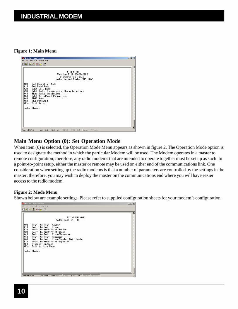
Figure 1: Main Menu
Main Menu Option (0): Set Operation ModeWhen item (0) is selected, the Operation Mode Menu appears as shown in figure 2. The Operation Mode option isused to designate the method in which the particular Modem will be used. The Modem operates in a master toremote configuration; therefore, any radio modems that are intended to operate together must be set up as such. Ina point-to-point setup, either the master or remote may be used on either end of the communications link. Oneconsideration when setting up the radio modems is that a number of parameters are controlled by the settings in themaster; therefore, you may wish to deploy the master on the communications end where you will have easieraccess to the radio modem.
Figure 2: Mode MenuShown below are example settings. Please refer to supplied configuration sheets for your modem’s configuration.
11
(0) Point-to-point MasterThe Modem operates in a master/remote configuration. When designated as a master in point-to-point mode, theradio modem will call any or all remotes it is instructed to call in the call book. The master determines the settingsused for all Radio Transmission Characteristics, regardless of the settings in the remotes and/or repeaters.
(1) Point-to-Point RemoteWhen set up as a point-to-point remote, an Modem will communicate with any master in its call book, eitherdirectly or through one or two repeaters. When functioning as a remote, the Entry to Call feature in the radiomodem’s call book (Figure 3) is not operational. The remote will communicate with any master on the list thatcalls.
(2) Point-to-Multi-Point MasterThe Modem may be set to run in multi-point mode, which allows one master to simultaneously be incommunication with numerous remotes. A point-to-multi-point master will communicate only with other radiomodems designated as point-to-multi-point remotes or point-to-multi-point repeaters.
3) Point-to-Multi-Point RemoteSetting (3) allows the radio modem to operate as a remote in a multi-point network. Please refer to the sectionentitled multi-point Operation, for more information on running a multi-point network.
(4) Point-to-Point Remote/RepeaterOption 4 allows you to designate the radio modem to act as either a remote or a repeater, depending upon theinstructions received from the master for the specific communications session. When a radio modem is placed inan ideal location, this setting offers the flexibility of using that radio modem as an end point in the communicationslink (remote) or to extend the link to a point further (repeater). These functions are not, however, availablesimultaneously (the radio modem cannot act as both a remote and a repeater at the same time).
A word of caution: Configured as a repeater, a radio modem has no security features as explained below.When a radio modem is designated as a point-to-point remote/repeater, it will allow any master to use it asa repeater.
(5) Point-to-Point RepeaterRadio Modems allow the use of up to two repeaters in a communications link, significantly extending theoperating range. When designated as a repeater, a radio modem behaves as a pass-through link. All settings for thecall book, baud rates, and radio transmission characteristics are disabled. A repeater will connect with any masterthat calls it (the repeater must still be set up in the master’s call book).
The use of one repeater in a communications link will reduce the top data throughput available when comparedto a direct master to remote link (generally on the order of 50%). This impact is generally noticed only when usingthe radio modems at 115.2 Kbaud. The throughput does not decrease further if two repeaters are used.
MODEM CONFIGURATION

12
INDUSTRIAL MODEMRF115
(6) Point-to-Point Remote/Master SwitchableMode 6 is a versatile option that allows the radio modem to be controlled entirely through software commands.When in mode 6, a number of key parameters in the radio modem’s user interface may be changed either directly(as if using the Windows Terminal program) or through the use of script files. In addition, when the radio modemis in mode 6 and not calling a remote, it will be a remote itself and accept any appropriate calls from other radiomodems.
In mode 6:
· The radio modem remains in remote mode until called by another radio modem in its Call Book orinstructed to call another radio modem through an ATDT command. The master will disconnect whenDTR goes low..
· The user may change settings in the user interface without using the reset button (this may be ofparticular value if the radio modem is not in an easily accessible location).
· Predetermined script files may be used which allow some of the radio modem’s settings to be changedupon execution of that file. This, in turn, allows the user to establish command sets that will instruct theradio modem to call a predetermined remote.
Note: For a detailed explanation covering the features of Mode 6, please contact the factory.
(7) Point-to-Multi-Point RepeaterSetting (7) allows the radio modem to operate as a repeater in a multi-point network. Please refer to the sectiontitled, “Multi-Point Operation”, for more information on running a multi-point network.
(F) Ethernet OptionsThis menu is only needed for the SRM6210E Ethernet modems. When using the Modem, this setting should beleft at factory default.
Main Menu Option (1): Set Baud RateWhen option (1) is selected you will be able to change the radio modem’s RS232 baud rate. This is thecommunication rate between the radio modem and the instrument to which it is connected. It is important to notethat this is independent of the baud rate for the other radio modem(s) in the communication loop. For example,Modems may be used in an application to send data from remote process instrumentation to an engineer’scomputer. In this application, the baud rate for the radio modem on the instrumentation might be set to 9600, andthe radio modem on the computer might be set to 57,600 or 115,200.
In general, it is desirable to set the baud rate to the highest level supported by the device to which it is connected.However, please note that this may actually result in slower data communications if the UART chipset of theconnected device does not support higher data rates.

13
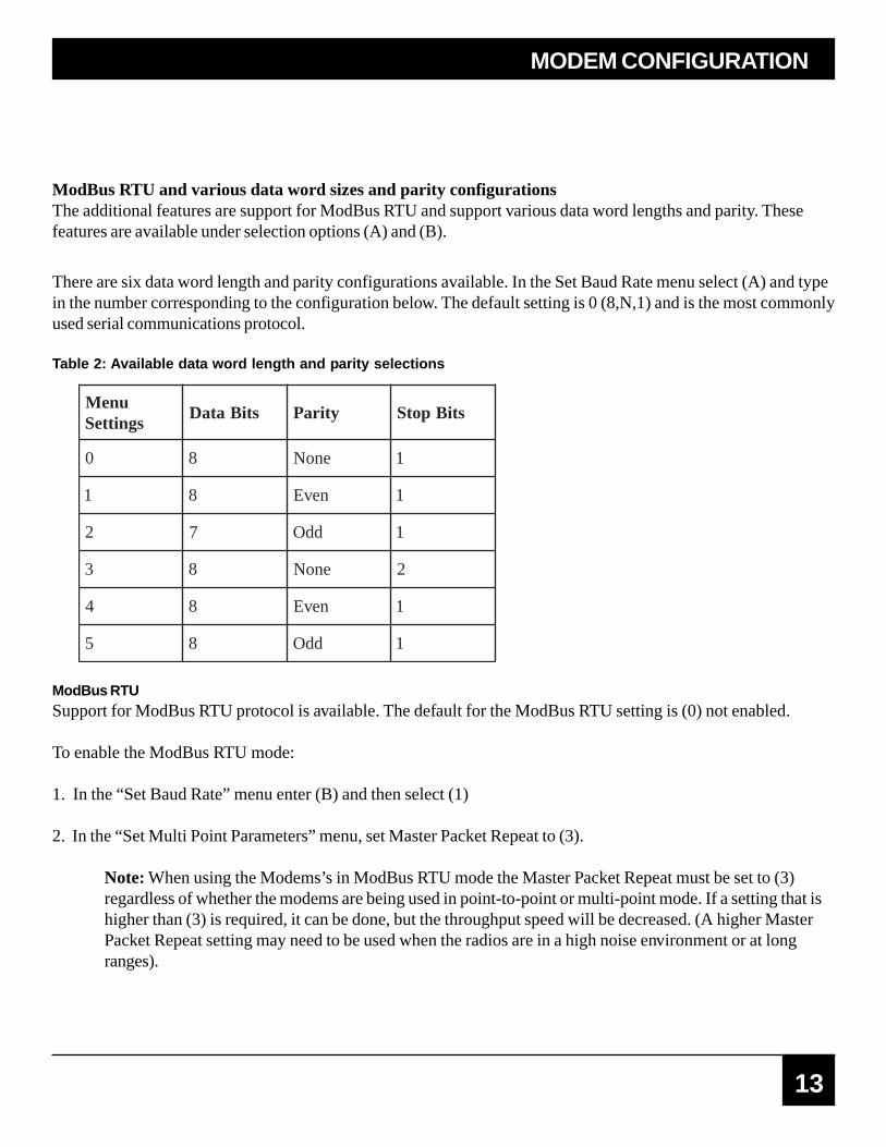
ModBus RTU and various data word sizes and parity configurationsThe additional features are support for ModBus RTU and support various data word lengths and parity. Thesefeatures are available under selection options (A) and (B).
There are six data word length and parity configurations available. In the Set Baud Rate menu select (A) and typein the number corresponding to the configuration below. The default setting is 0 (8,N,1) and is the most commonlyused serial communications protocol.
Table 2: Available data word length and parity selections
uneMsgnitteS
stiBataD ytiraP stiBpotS
0 8 enoN 1
1 8 nevE 1
2 7 ddO 1
3 8 enoN 2
4 8 nevE 1
5 8 ddO 1
ModBus RTUSupport for ModBus RTU protocol is available. The default for the ModBus RTU setting is (0) not enabled.
To enable the ModBus RTU mode:
1. In the “Set Baud Rate” menu enter (B) and then select (1)
2. In the “Set Multi Point Parameters” menu, set Master Packet Repeat to (3).
Note: When using the Modems’s in ModBus RTU mode the Master Packet Repeat must be set to (3)regardless of whether the modems are being used in point-to-point or multi-point mode. If a setting that ishigher than (3) is required, it can be done, but the throughput speed will be decreased. (A higher MasterPacket Repeat setting may need to be used when the radios are in a high noise environment or at longranges).
MODEM CONFIGURATION
14
INDUSTRIAL MODEMRF115
RS232/485 and Turnoff delayThese settings do not pertain to the Modem.
Flow controlThis setting allows for the use of hardware handshaking. Most applications do not require handshaking whenusing the Modem. The default setting is 0 (no handshaking).
gnitteSuneM troP
0 enoN
1 STR
2 RTD
Main Menu Option (2): Edit Call BookThe Call Book is an innovative feature in the Modemthat offers both security and flexibility in use. The Call Bookaccomplishes this by allowing the user to determine with which other Modems a given radio modem willcommunicate, based on the Call Book numbers for both the master and remote. The radio modem’s Call Booknumber is encoded in the microprocessor and identified on a label on the modem. The instructions provided in thissection are for point-to-point mode only. Use of the Call Book for multi-point systems is explained later in thischapter. For two Radio Modems to communicate in point-to-point mode, three events must occur:
1. The call book number for the master must be listed in the remote’s Call Book.2. The call book number for the remote must be listed in the master’s Call Book.3. The master must be programmed to call the remote.
As shown in figure 3, the Call Book allows users to set up a list of up to 10 Modems to communicate with.Designate up to 2 repeaters to be used in communicating with a given radio modem, and tell the master whichremote to call. To direct the master to call a remote, the Remote must be in the Call Book Menu. A specific remotemay be called by entering (C) at the prompt, followed by the menu number corresponding to that remote. To callany available remote in the list, the user should enter C and then A (for All).
Note: To call a remote through one or two repeaters, you must call that remote directly (as opposed tousing the Call All option). When Call All is selected the master is not able to connect with any remotesthrough repeaters. This is because the master calls every remote in the list when instructed to call all andwill connect with the first remote to respond. When calling through a repeater, the master must first callthat repeater and establish a communications link with it prior to making contact with the remote.

15
Figure 3: Call Book MenuShown below are example settings. Please refer to supplied configuration sheets for your modem’s configuration.
Entering or Modifying Numbers in the Call BookEntering or modifying call book numbers in the Call Book is a straightforward process. When in the Call Bookmenu, select the entry number (0 – 9) you wish to edit. You will be prompted for the new number (formatting isautomatic, you do not need to enter the dash). Once the number is entered (unless it is 000-0000) you will beasked for the call number of the first repeater to be used. If no repeater is to be used, enter the escape key; yourentry will be complete and you will be back in the Call Book menu screen. If you enter a repeater number, youwill then be prompted for the call number of the second repeater to use. If a second repeater is being used, enterthe call number at this time; if not, enter the escape key. Once again, the radio modem will retain your entries, asshown in the updated Call Book menu screen.
Note: It is important that the Call Book slots (0 – 9) are filled sequentially beginning with 0, the first slotin the book. Call Book numbers do not need to be entered in numerical order; however, there must not beany 000-0000 numbers in the middle of the list of good Call Book numbers. The reason for this is thatwhen a master is instructed to Call All available remotes, it will call all remotes listed until it reaches thefirst number of 000-0000. If a valid call book number is entered after the all zero number, it will not berecognized as a valid number to be called by the master.
M O D E M C O N F I G U R AT I O N

16
INDUSTRIAL MODEMRF115
Edit Call Book in Multi-Point SystemsIn a multi-point system, the remotes and repeaters are not listed in the master’s Call Book. When establishing sucha system, it is necessary only to have the master’s Call Book number in each remote’s and repeater’s Call Book,and to have each repeater’s Call Book number in the Call Book of each remote which may potentiallycommunicate through it.
The following example shows the Call Books of a multi-point system comprised of a master, repeater and remotein which the remote can communicate either through the repeater or directly to the master:
Multi-Point Master Call Book (Unit Call Book number 555-0001)
yrtnE rebmuN 1retaepeR 2retaepeR
)0( 0000-000
)1( 0000-000
No call book number entries are necessary in the master’s Call Book. The master’s Call Book may beprogrammed to call any entry
Multi-Point Repeater Call Book (Unit Call Book number 555-0002)
yrtnE rebmuN 1retaepeR 2retaepeR
)0( 1000-555
)1( 0000-000
Multi-Point Remote Call Book (Unit Call Book number 555-0003)
yrtnE rebmuN 1retaepeR 2retaepeR
)0( 1000-555
)1( 2000-555
)2( 0000-000
Main Menu Option (3): Edit Radio Transmission CharacteristicsWhen option (3) is selected in the main menu the screen in figure 4 appears, which allows the user to modify theradio transmission characteristics of the radio modems. As stated in the warning, these parameters are for theexperienced user who has a good understanding of the principles of radio data transmission. They should bechanged only after consulting this user guide.

17
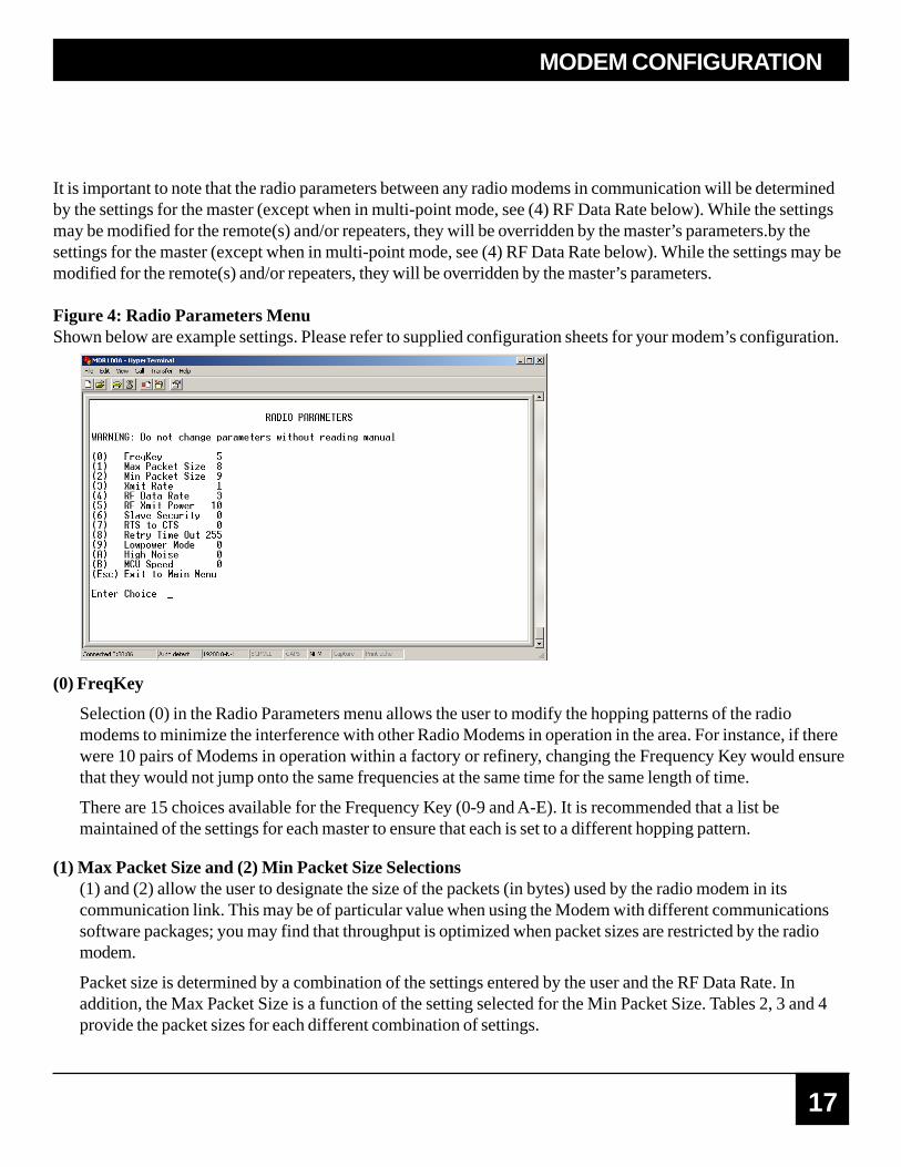
It is important to note that the radio parameters between any radio modems in communication will be determinedby the settings for the master (except when in multi-point mode, see (4) RF Data Rate below). While the settingsmay be modified for the remote(s) and/or repeaters, they will be overridden by the master’s parameters.by thesettings for the master (except when in multi-point mode, see (4) RF Data Rate below). While the settings may bemodified for the remote(s) and/or repeaters, they will be overridden by the master’s parameters.
Figure 4: Radio Parameters MenuShown below are example settings. Please refer to supplied configuration sheets for your modem’s configuration.
(0) FreqKey
Selection (0) in the Radio Parameters menu allows the user to modify the hopping patterns of the radiomodems to minimize the interference with other Radio Modems in operation in the area. For instance, if therewere 10 pairs of Modems in operation within a factory or refinery, changing the Frequency Key would ensurethat they would not jump onto the same frequencies at the same time for the same length of time.
There are 15 choices available for the Frequency Key (0-9 and A-E). It is recommended that a list bemaintained of the settings for each master to ensure that each is set to a different hopping pattern.
(1) Max Packet Size and (2) Min Packet Size Selections(1) and (2) allow the user to designate the size of the packets (in bytes) used by the radio modem in itscommunication link. This may be of particular value when using the Modem with different communicationssoftware packages; you may find that throughput is optimized when packet sizes are restricted by the radiomodem.
Packet size is determined by a combination of the settings entered by the user and the RF Data Rate. Inaddition, the Max Packet Size is a function of the setting selected for the Min Packet Size. Tables 2, 3 and 4provide the packet sizes for each different combination of settings.
MODEM CONFIGURATION
18
INDUSTRIAL MODEMRF115
Table2: Minimum Packet Size Settings (bytes)
Table3: Maximum Packet Size Settings where RF Data Rate=3
gnitteStekcaPniMataDFReziS
2=etaRgnitteS
tekcaPniMeziS
ataDFR3=etaR
0 61 0 8
1 12 1 21
2 62 2 61
3 23 3 02
4 73 4 42
5 24 5 82
6 84 6 23
7 35 7 63
8 85 8 04
9 46 9 44
0 1 2 3 4 5 6 7 8 9
0 8 42 04 65 27 88 401 021 631 251
1 21 82 44 06 67 29 801 421 041 651
2 61 23 84 46 08 69 211 821 441 061
3 02 63 25 86 48 001 611 231 841 461
4 42 04 65 27 88 401 021 631 251 861
5 82 44 06 67 29 801 421 041 651 271
6 23 84 46 08 69 211 821 441 061 671
7 63 25 86 48 001 611 231 841 461 081
8 04 65 27 88 401 021 631 251 861 481
9 44 06 67 29 801 421 041 651 271 881

19
Table 4: Maximum Packet Size Settings where RF Data Rate=2
0 1 2 3 4 5 6 7 8 9
0 51 63 85 97 001 121 341 461 581 602
1 02 24 36 48 501 721 841 961 091 212
2 62 74 86 09 111 231 351 571 691 712
3 13 25 47 59 611 731 951 081 102 222
4 63 85 97 001 121 341 461 581 602 822
5 24 36 48 501 721 841 961 091 212 332
6 74 86 09 111 231 351 571 691 712 832
7 25 47 59 611 731 951 081 102 222 442
8 85 97 001 121 341 461 581 602 822 942
9 36 48 59 721 841 961 091 212 332 452
(3) Xmit RateThere are two settings for the Transmit Rate parameter. For normal operation the Modem should be set atTransmit Rate 1. Transmit Rate 0 is useful to qualitatively gauge signal strength. When set to Transmit Rate 0the radio modems will transmit data back and forth continuously, and the strength of the signal may be gaugedby viewing the Show Radio Statistics option.
Due to the fact that the radio modems transmit continuously when Transmit Rate is set to 0 (whether or notthey have data to send) they use radio frequency spectrum unnecessarily. Therefore, Transmit Rate 0 should beused only as a diagnostic tool and not for normal operation.
(4) RF Data RateThe Modem has two settings for the RF Data Rate (not to be confused with the RS232 Baud Rate). Setting 2should be used when the radio modems are close together and data throughput is to be optimized. Setting 3should be used when the radio modems are farther away and a solid data link is preferred over datathroughput.
Note: The RF Data Rate setting must be identical for all units in the system. Any radio modem with adifferent RF Data Rate than the master will not establish a communication link.
MODEM CONFIGURATION

20
INDUSTRIAL MODEMRF115
(5) RF Xmit PowerThe Modem offers users the ability to modify the Transmission Power of the radio modem. There are 10power settings available (1-10) which are roughly linear. Therefore a setting of 10 is full power (or 1 Watt)and 1 is 10% power (or 100 mw). The following guidelines should be followed when setting the RFTransmission Power:
(6) Remote SecurityWith option 6 the user may disable the radio modem’s security so it will accept a call from any other Modem.The default setting is 0 where security is enforced (the caller’s call book number must be in the remote’s CallBook). With a setting of 1 security is disabled.
As mentioned in mode 6, Remote Security must be set to 1 when the unit is operating in a point-to-pointsystem where it may need to accept calls from more than 10 different Modems. However, it is important tonote that when Remote Security is set to 1, the radio modem will accept calls from any other Modem, andadditional system security measures should be taken to prevent unauthorized access.
(7) RTS to CTSMenu selection 7 in the Radio Parameters provides the option of allowing the RTS line (pin 7) on the masterradio modem to control the CTS line (pin 8) of the remote. This pass-through control can be enabled in point-to-point mode as well as point-to-multi-point. In the latter, the master RTS line will control all remotes’ CTSlines. When this mode is enabled the CTS line ceases to function as flow control. Therefore it is notrecommended to enable this feature when operating at RS-232 speeds above 38.4 KB.
To enable this mode, enter 7 in the Radio Parameters menu. An entry of (1) will enable the RTS-CTS control a(0) will disable it.
gnitteS leveLrewoP nehWdesU
3-1 woLemasnihtiwgnitareposmedomoidarfo)s(riaP
.smoorgniniojdaro
6-4 muideMgnitareposmedomoidarforiapenonahteroM
.ytilicafemasehtnihtiw
01-7 lluF ytilicafadnoyebgnidnetxenoitarepolamroN

21
(8)Retry Time OutThe Retry Time Out parameter allows the use to determine when a remote will drop a connection to a master orrepeater in multi-point mode. The default setting is 255, meaning that if one packet in 255 from the master is sentsuccessfully to the remote, it will maintain a link. The lowest setting is 8, at which a remote will drop a connectionmuch faster.
The Retry Time Out parameter is useful when a multi-point system is used with a moving master or remotes. Asthe link gets weaker, a lower setting will allow a remote to drop it’s link and search for a stronger connection.
While intended primarily for multi-point systems, the Retry Time Out parameter may also be modified in point-to-point systems. In point-to-point mode the Retry Time Out should not be set to a value of less than 151.
(9) Lowpower ModeThe Lowpower Mode is an option that, when enabled, allows the Modem to use less power when set as a multi-point remote.
With a setting of 2 through 63, the Modem will sleep between slots. For example, at a setting of 2, the Modemsleeps 1 out of 2 slots, at a setting of 3, the Modem sleeps 2 out of 3 slots, and so on.
Note:
1. The Lowpower mode is for use only in point to multi-point systems and only on the multi-pointremotes. The power savings occur when the option is enabled and the remote has a link to its master orrepeater. There are no power consumption savings when the remote is transmitting data back to the master.Designed primarily for SCADA systems, the Lowpower Mode is of little value when significant amountsof data is being sent from the remote to the master.
2. Because the Lowpower mode puts the transceiver to sleep, a latency will be introduced before itbecomes fully linked to the master. This latency can range from 6 ms to 2.5 seconds.
3. To communicate to the RS232 port of a Modem that is in Lowpower Mode, the RTS line must be heldhigh to wake it up. The Modem will wake up within approximately 20 milliseconds or when CTS goeshigh.
4. If the RTS line on the remote is held high, the Modem will remain in normal operation regardless of theLowpower Mode setting.
MODEM CONFIGURATION

22
INDUSTRIAL MODEMRF115
(A) High NoiseUse the menu to indicate if the modem will be operated in an environment with a high degree of radio noise andinterference.
With a setting of 1, the rejection of interference is improved, at the cost of reduced range and/or throughput.
(B) MCU speed Use this menu to set the speed of the MCU (processor) in the modem.
Note: Only needed when the Modem is set to 115.2Kbaud (or above).
gnitteS noitpircseD setoN
0 deepswoL noitpmusnoctnerrucsecudeR
1 deepshgiH duabK032rofderiuqeR
Main Menu Option (4): Show Radio StatisticsOption (4) in the main menu allows the user to view data transmission statistics, which have been gathered by theTransceiver during the most recent session. Statistics are gathered during each data link and are reset when thenext link begins. Ideally, noise levels should be below 30, and the difference between the average signal level andaverage noise level should be 30 or more. High noise levels tend to indicate other sources of RF interference,while low signal levels indicate a weak link. The “Local” stats are the statistics that are being gathered by themodem you are connected to while “Remote1, Remote2, and Remote3” are the stats of the repeater(s) that themodem you are attached to is using to get back to the master modem. The following sections provide informationuseful to the process of troubleshooting and improving radio links.
Average Noise LevelThe average noise level indicates the level of background noise and interference at this modem and at each of themodems used as repeaters in the link. The number is an average of the noise levels measured at each frequency inthe modems’ frequency hop table. The individual measurement values at each frequency hop channel are shownin the frequency table. The frequency table is accessed by pressing the ENTER key on the computer when theradio statistics menu is displayed. Average noise levels will typically fall in the range of 15 to 30. Average noiselevels significantly higher than this are an indication of a high level of interference that may degrade theperformance of the link. High noise levels can often be improved with bandpass filters, antenna placement orantenna polarization. Please contact Black Box for more information.

23
leveLlangiSegarevA 14 94 06 55 58
mBdnileveL 011- 001- 09- 08- 07-
Overall Rcv Rate (%)The Overall Rcv Rate measures the percentage of data packets that were successfully transmitted from the masterto the remote on the first attempt without requiring retransmission. A number of 75 or higher indicates a robust linkthat will provide very good performance even at high data transmission rates. A number of 25 or lower indicates aweak or marginal link that will provide lower data throughput. An Overall Rcv Rate of 100% will provideapproximately 100 Kbaud of bandwidth with an RF data rate of 3 (Radio Transmission Parameters Menu) andapproximately 150 Kbaud of bandwidth with an RF Data Rate of 2. These numbers are reduced approximately50% if there are one or more repeaters in the network.
Number of DisconnectsIf, during the course of performing a link test, the link between the master and the remote is broken, and the radioslose carrier detect, the occurrence is recorded in the Number of Disconnects value. The value indicates the totalnumber of disconnects that have occurred from the time the link test started until the radio was put into configmode. Under normal operating conditions, the number of disconnects should be 0. One or more disconnects mayindicate a very weak link, the presence of severe interference problems or loss of DC power to the Master orRepeater if one is present.
Note: a remote and/or repeater will record a disconnect if the system master is placed into configurationmode or has power interrupted while the remote and/or repeater is linked to the master
MODEM CONFIGURATION
Average Signal LevelThe average signal level indicates the level of received signal at this modem and at each of the modems used asrepeaters in the link. For each of these, the signal source is the modem that transmits to it. The number is anaverage of the received signal levels measured at each frequency in the modem’s frequency hop table. Theindividual measurement values at each frequency hop channel are shown in the frequency table. The frequencytable is accessed by pressing the ENTER key on the computer when the radio statistics menu is displayed.
For a reliable link, the average signal level should be at least 30 greater than the average noise level reading. Thetable below provides an approximate conversion of average signal level values into the more common dBm(decibel milliwatts). Low Average Signal Levels can often be corrected with higher gain antennas, antennaplacement, and use of repeaters. Contact Black Box for more information.

24
INDUSTRIAL MODEMRF115
Radio TemperatureThe radio temperature value is the current operating temperature of the radio in degrees C (Celsius.) For properoperation, the Radio Modems must be in the range of –400 to 750 C.
Multi-Point OperationIn a multi-point system, a radio modem designated as a master is able to simultaneously be in communication withnumerous remotes. In its simplest form, a multi-point network functions with the master broadcasting its messagesto all remotes and the remotes responding to the master as appropriate.
Traditionally, a multi-point network is used in applications where data is collected from many instruments andreported back to one central site. As such, the architecture of such a system is completely different from point-to-point applications. The theoretical maximum number of remotes that can be configured into a multi-point networkis a function of the data throughput needed from each of the remotes. For example, if the network will be pollingremotes once a day to retrieve sparse data, several hundred remotes could be configured to a single master. If, onthe other hand, each remote will be transmitting data at greater levels then fewer remotes may be connected to themaster (the overall system will be closer to capacity with fewer remotes).
The theoretical limit of a multi-point system is influenced by the following parameters:
· Size of the blocks of data—the longer the data blocks the greater the system capacity· RS232 baud rate· The amount of contention between remotes· Use of repeaters—a single repeater in a multi-point network will decrease overall system capacity by 50%; more than one repeater does not further decrease network capacity.

25
Main Menu Option (5): Edit Multi-Point Parameters
Figure 5: Multi-Point ParametersShown below are example settings. Please refer to supplied configuration sheets for your modem’s configuration.
In a multi-point network, it is critical to know how many radio modems are being used as repeaters. Any radiomodem that is used as a repeater essentially becomes a master to the remotes and other repeaters to which it iscommunicating. Therefore, the user must first identify how many repeaters are connected to the master byassigning a value in parameter (0) Number Repeaters. This parameter must also be set for each repeater in thesystem (i.e., in the event that a repeater is connected to one or more other repeaters). This parameter does need tobe set for multi-point remotes.
In point-to-point operation, the Radio Modems acknowledge every data packet transmitted. In a multi-pointnetwork, the remotes do not acknowledge transmissions from a master to the remotes. This is to prevent systemoverload. If the remotes acknowledged all data transmissions from the master in a large multi-point system, then allsystem capacity would be spent having the master listen for acknowledgments from the remotes. Because thetransmission is not acknowledged by the remotes, 100% confidence does not exist that every remote has receivedevery message from the master. To address this issue, the user may modify option (1) Master Packet Repeat,assigning a value between 0 (the packet is transmitted once) to 9 (the packet is repeated 9 times). For networkswith solid RF links, this parameter would be set at the lower end of the scale (0-1). If the network has some weakor marginal links, it would be set toward the higher values. If a remote receives a packet from a master more thanonce, it will discard the repeated packets received.
While packets transmitted from the master to the remotes in a multi-point network are not acknowledged, packetstransmitted from remotes to the master are. However, it is possible that more than one remote will attempt totransmit to the master at the same time, and it is therefore important that a protocol exists to resolve contention forthe master between remotes.
MODEM CONFIGURATION

26
INDUSTRIAL MODEMRF115
This is addressed through parameters (2) Max Remote Retry and (3) Retry Odds. The Max Remote Retrysetting defines how many times (0 to 9) the remote will attempt to retransmit a packet to the master beforebeginning to use a back-off algorithm. Once the remote has unsuccessfully attempted to transmit the packet thenumber of times specified in Max Remote Retry, it will attempt to transmit to the master on a random basis.
The Retry Odds parameter determines the probability that the remote will attempt to retransmit the packet to themaster; a low setting will assign low odds to the remote attempting to transmit and conversely a high setting willassign high odds. An example of how this parameter might be used would be when considering two differentremotes in a multi-point network, one close in with a strong RF link and the other far from the master with a weaklink. It may be desirable to assign a higher Retry Odd to the remote with the weaker link to give it a better chanceof competing with the closer remote for the master’s attention.
Another parameter in a multi-point network is (4) DTR Connect. When set at (1), the remote will connect to themaster if it is free when the DTR line goes high on the 9-pin RS232 connector. In setting (2), the radio modemwill accumulate data in its buffer and transmit in a burst when the buffer is full. This mode is valuable when anetwork has many low data rate devices and it is desirable to increase overall network capacity. In setting (0), theradio modem will transmit when RS232 data is received.
The repeater’s hopping pattern must also be set in a multi-point network; this is accomplished with parameter (5)Repeater Frequency. Setting this parameter is in contrast with point-to-point mode where the repeaterautomatically uses the master’s hopping pattern. The repeater may be programmed to either use the master’shopping pattern selection (0) or its own selection (1).
Option (6) NetWork ID allows multi-point networks to be established without the use of the Call Book. If theNetWork ID is set to any value lower than the default (255), the remotes in the multi-point network willcommunicate with the first multi-point master or repeater heard with the same NetWork ID. When the NetWorkID is used, multi-point masters and repeaters may be replaced without reprogramming all of the remotes in thenetwork. In addition, this allows a remote to establish communications with different masters (though not at thesame time) without having the call book numbers in the Call Book. This is very useful in mobile multi-pointapplications. (8) MultiMaster Synch is reserved for multi-point applications with concentrations of master unitswhere it is necessary to reduce interference between the masters. Please contact the factory for more informationon the use of this feature. The (9) 1PPS Enable/Delay This setting should not be changed from its default of 255.Contact the factory for further information.

27
(A) Remote/RepeaterThe remote/repeater mode allows a Modem in a multi-point system to simultaneously act as a remote and arepeater. When in this mode, a Modem will repeat any packets sent from a master as well as send them out theRS232 port. This allows a Modem set as a repeater to act as a remote at the same time. 0 disables this mode, 1enables it. For this feature to work, the modem must be configured as a point-to-multipoint repeater.
(B) DiagnosticsThe Modem has the ability to run a diagnostic program while in normal operations. Contact the factory foradditional information.
(C) SubNet IDThe default setting is “Disabled.” Please see the SubNet ID section of this user guide.
(D) Radio IDUsed with the Diagnostics. Contact the factory for additional information.
SubNet IDThis series of modems offer a SubNet ID system for use in multi-point networks using Network ID. This featureallows the users to dictate what path a given repeater or remote will use to achieve a link to the network master.For example, if a remote modem in a given network has line of sight to the network master and one or morerepeaters, but only one repeater is close to that remote, SubNet ID can be used to link that master with the properrepeater only.
Note: This feature can only be used in networks using Network ID with one or more repeaters.
There are two components to SubNet ID. The first is the Xmit (transmit) SubNet ID, and the second is Rcv(receive) SubNet ID. The Xmit SubNet ID is used only by repeaters and is the ID that a repeater sends out whensending data to other repeaters or remotes. The Rcv SubNet ID is the ID that repeaters or remotes look for toreceive data.
Note: The master is not affected by these settings. Only repeaters and remotes use these settings. Remotesonly use Rcv SubNet ID
MODEM CONFIGURATION

28
INDUSTRIAL MODEMRF115
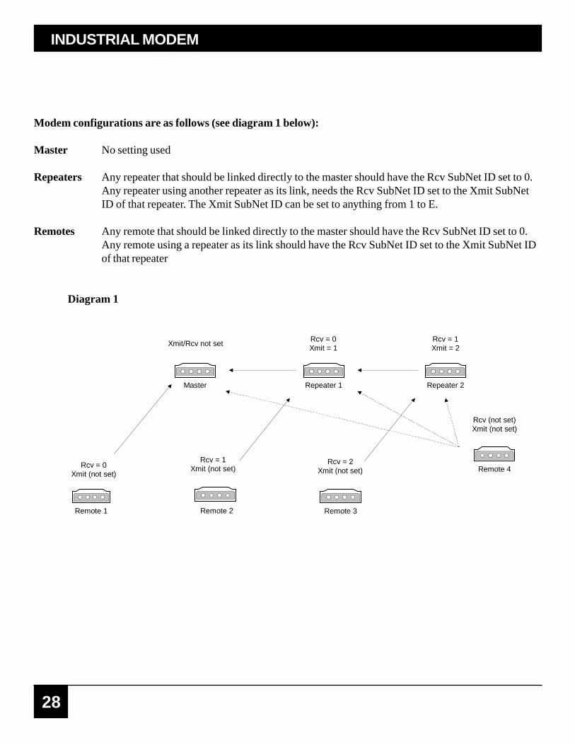
Modem configurations are as follows (see diagram 1 below):
Master No setting used
Repeaters Any repeater that should be linked directly to the master should have the Rcv SubNet ID set to 0.Any repeater using another repeater as its link, needs the Rcv SubNet ID set to the Xmit SubNetID of that repeater. The Xmit SubNet ID can be set to anything from 1 to E.
Remotes Any remote that should be linked directly to the master should have the Rcv SubNet ID set to 0.Any remote using a repeater as its link should have the Rcv SubNet ID set to the Xmit SubNet IDof that repeater
Diagram 1
Master Repeater 1 Repeater 2
Xmit/Rcv not setRcv = 0Xmit = 1
Rcv = 1Xmit = 2
Remote 1
Rcv = 0Xmit (not set)
Remote 2
Rcv = 1Xmit (not set)
Remote 3
Rcv = 2Xmit (not set) Remote 4
Rcv (not set)Xmit (not set)
29
Main Menu Option (8): PasswordCaution: If the password feature is enabled and you want cannot remember the password, the radio modem willhave to be returned to Black Box to have the password disabled. Use with caution.
Option (8) in the Main Menu allows the user to set a password, which will prevent un-authorized users to changethe configuration of the modem.
Setting a PasswordTo enable the Password feature choose (8) from the Main Menu. You will be prompted with “New PW?” (<esc>to exit)
To back out of the process and not enable the password, hit escape. To set a password, type in exactly 4characters. At any point in the process you can cancel by hitting the escape key. Once the 4 characters have beenentered, you will be prompted with “<enter> to accept, <esc> to quit”.
At this point, if you wish to accept the password entered and enable the feature, press the enter key. The passwordthat you have chosen is displayed on the line above (please note that the password is case sensitive). To quit theprocess and not enable the password, press escape.
Changing a PasswordOnce the password feature has been enabled, it is possible to change to a new password. To enter a new passwordselect (8) from the Main Menu. You will be prompted with “Enter Security Code”. Enter the current password.Once the password has been entered correctly (it is case sensitive) you will be prompted to enter the newpassword. At any point this process may be cancelled by pressing escape.
Disabling PasswordThe process to disable the password is similar to the process to change the password. However, when prompted toenter the new password, the following procedure needs to be followed:
1. Hold the “Alt” key down and using the number key pad (not the numbers across the top of the key board) type “0255”
2. Release the “Alt” key
3. Repeat steps 1 and 2 three more times (this will enter 0255 a total of four times).
4. You will be prompted with “<Enter> to accept, <esc> to quit.
5. Hit the “Enter” key to disable the password or hit the escape key to keep the password
MODEM CONFIGURATION

30
INDUSTRIAL MODEMRF115
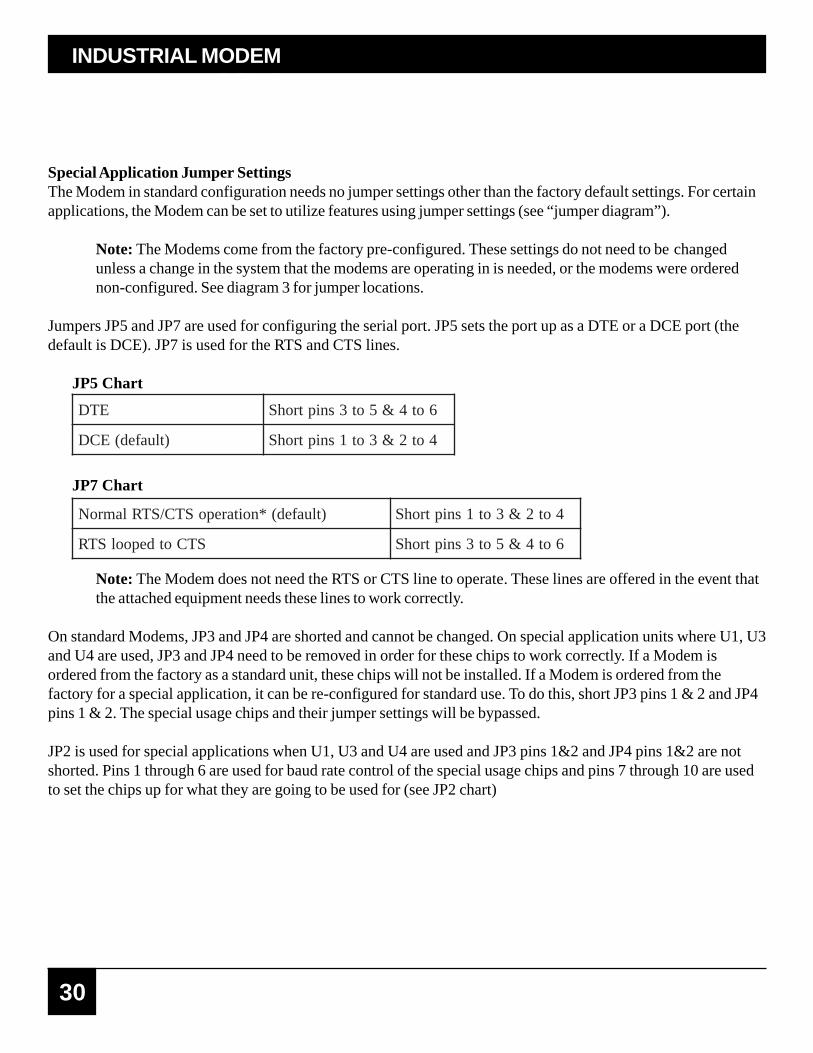
Special Application Jumper SettingsThe Modem in standard configuration needs no jumper settings other than the factory default settings. For certainapplications, the Modem can be set to utilize features using jumper settings (see “jumper diagram”).
Note: The Modems come from the factory pre-configured. These settings do not need to be changedunless a change in the system that the modems are operating in is needed, or the modems were orderednon-configured. See diagram 3 for jumper locations.
Jumpers JP5 and JP7 are used for configuring the serial port. JP5 sets the port up as a DTE or a DCE port (thedefault is DCE). JP7 is used for the RTS and CTS lines.
JP5 Chart
JP7 Chart
ETD 6ot4&5ot3sniptrohS
)tluafed(ECD 4ot2&3ot1sniptrohS
Note: The Modem does not need the RTS or CTS line to operate. These lines are offered in the event thatthe attached equipment needs these lines to work correctly.
On standard Modems, JP3 and JP4 are shorted and cannot be changed. On special application units where U1, U3and U4 are used, JP3 and JP4 need to be removed in order for these chips to work correctly. If a Modem isordered from the factory as a standard unit, these chips will not be installed. If a Modem is ordered from thefactory for a special application, it can be re-configured for standard use. To do this, short JP3 pins 1 & 2 and JP4pins 1 & 2. The special usage chips and their jumper settings will be bypassed.
JP2 is used for special applications when U1, U3 and U4 are used and JP3 pins 1&2 and JP4 pins 1&2 are notshorted. Pins 1 through 6 are used for baud rate control of the special usage chips and pins 7 through 10 are usedto set the chips up for what they are going to be used for (see JP2 chart)
)tluafed(*noitarepoSTC/STRlamroN 4ot2&3ot1sniptrohS
STCotdepoolSTR 6ot4&5ot3sniptrohS
31
JP2 Chart/Baud Rate
JP2 Chart/Chip Operation
2-1sniP 4-3sniP 6-5sniP etarduaB
ffO ffO ffO 2.91
ffO ffO nO 2.511
ffO nO ffO 6.75
ffO nO nO 4.83
nO ffO ffO 0069
nO ffO nO 0084
nO nO ffO 0042
nO nO nO 0021
8-7sniP 01-9sniP noitarepopihC
ffO ffO )drowtib01syawla(retsamstcennoC
ffO nO drowtib01eslupkaerB
nO nO drowtib11esulpkaerB
MODEM CONFIGURATION

32
INDUSTRIAL MODEMRF115
Diagram 2

33
Modem Location
MODEM LOCATION
Placement of your Modem is likely to have a significant impact on its performance. In general, the rule of thumbwith the Modem is that the higher the placement of the antenna, the better the communication. In practice youshould also place the radio modem itself away from computers, telephones, answering machines, and other similarequipment. A 6-foot RS232 cable will usually provide ample room for placement away from other equipment. Toimprove the data link, Black Box offers directional and omni directional antennas with cable lengths ranging from10 to 250 feet.
When using an external antenna, placement of that antenna is critical to a solid data link. Other antennas in closeproximity are a potential source of interference. It is also possible that slight adjustments in antenna placement (aslittle as 2 feet) will solve noise problems. In extreme cases, such as when the radio modem is located close topager or cellular telephone transmission towers, Black Box offers a band pass filter to reduce the out of bandnoise.
Using an External AntennaIn certain circumstances it may be desirable to extend the range of the Modem radio modem by using an externalantenna in place of the standard whip antenna. The radio modem is equipped with a standard SMA external jack.This allows the use of external omni directional or yagi antennas. These are part of kits provided by Black Boxand include coax cable. These antennas allow versatility in the Modems deployment, extending its range andallowing it to get around obstructions.
The use of an external antenna may radically improve the results obtained with radio modems. It is imperative toobtain line of sight with the antennas, and changes in placement height of as few as a couple of feet may make thedifference between no link and one that is solid and reliable.
Choose from the following:Omni directional with Bracket Mount and 10ft of cable (MDR151-0010-R2)Omni directional with Bracket Mount and 25ft of cable (MDR151-0025-R2)Omni directional with Bracket Mount and 50ft of cable (MDR151-0050-R2)Omni directional with Bracket Mount and 100ft of cable (MDR151-0100-R2)Yagi (Unidirectional) with Bracket Mount and 25ft of cable (MDR152-0025-R3)Yagi (Unidirectional) with Bracket Mount and 50ft of cable (MDR152-0050-R3)Yagi (Unidirectional) with Bracket Mount and 100ft of cable (MDR152-0100-R3)
If external directional antennas are used, FCC regulations concerning effective radiated power limitations must befollowed.

34
INDUSTRIAL MODEMRF115
Caution: Any antenna placed outdoors must be properly grounded. It is required by FCC regulations thatqualified personnel experienced in antenna installation and familiar with local codes and regulationscomplete the antenna installation. It is also required by FCC regulations that only approved antennas beused. Use extreme caution when installing antennas and follow all instructions included with the antennas.
The use of an external antenna subjects the radio modem to greater exposure to direct lightning strikes. It isstrongly recommended that a lightning arrestor be used on all outdoor antenna installations.Long RS232 cable runs should also be avoided in areas with increased lightning activity or static electricity unlessthey are properly isolated from the radio modem. Nearby lightning strikes or elevated levels of static electricitymay lead to voltage spikes on the line, causing failure in the radio modem’s RS232 interface. It is alsorecommended that the RS232 data cable not be located near high voltage power lines as this can causeinterference in data communications, damage the Modem as well as an increase in risk of personal injury.
35
The LEDs on the Modem’s front panel provide important information on the operation of the radio modem.Compare the status of a radio modem’s LEDs with the tables below to aid you in the troubleshooting process.
Table 6: LED Status in Point-to-PointP=power C=carrier detect I=data in O=data out
Modem Front Panel LEDs
RS deRdiloS
AF rebmAgnihsalF
YF wolleYgnihsalF
GF neerGgnihsalF
GM neerGyratnemoM
O ffO
AS rebmAdiloS
Data out LED lightsmomentarily when theconfiguration button isdepressed.
Table 7: LED Status in Multi-Point Mode
Legend
Data out LED lightsmomentarily when theconfiguration button isdepressed.
MODEM FRONT PANEL LEDS
noitarugifnoC retsaM etomeR retaepeR
srotacidnIDELP C I O P C I O P C I O
FRon,derewoPknil
RS O O O RS O O O RS O O O
knilFRdehsilbatse
RS O O O RS AS O O RS O O O
wolfataDotretsam
etomerRS AF YF O RS AS O GF RS AS O O
otetomerataDretsam
RS AF O GF RS AS YF O RS AS O O
noitarugifnoCedoM
RS AS O GM RS AS O GM RS AS O GM
noitarugifnoC retsaM etomeR retaepeR
srotacidnIDELP C I O P C I O P C I O
FRon,derewoPknil
RS O O O RS O O O RS O O O
knilFRdehsilbatse
RS AS O O RS AS O O RS O O O
wolfataDotretsam
etomerRS AS YF O RS AS O GF RS AS O O
otetomerataDretsam
RS AS O GF RS AS YF O RS AS O O
noitarugifnoCedoM
RS AS O GM RS AS O GM RS AS O GM

36
INDUSTRIAL MODEMRF115
RS232 Pin Assignments
Table 8: RS232 Pin Assignments
niP tnemngissA
1 tceteDreirraC
2 ataDtimsnarT
3 ataDevieceR
4 RTD
5 dnuorG
6 ydaeRteSataD
7 STR
8 dneSotraelC
9 C/NDB9 Female
5 4 3 2 1
9 8 7 6
Sample Data Communication LinksThe Modem’s versatility allows data communication links to be established using a variety of differentconfigurations. This, in turn, makes it possible to extend the range of the Modem and get around obstacles.Diagram 3 shows the most common and straightforward link, a master communicating to a remote in a dedicatedlink.
Diagram 3
�������
���� ��
����

37
Diagram 4 depicts how a link might be set up using a repeater. The repeater may be sitting on a hilltop or otherelevated structure to link the master to the remote. In this setup, it may be desirable to use an external omnidirectional antenna on the repeater; to extend the range Yagi antennas could be used on either or both of the masterand remote.
Diagram 4
�������
���� ��
����
MODEM FRONT PANEL LEDS

38
INDUSTRIAL MODEMRF115
When a repeater is used the RF speed is cut in half, making 115,200 KBaud uncompressed throughputunachievable. The baud rate, however, may still be set at 115,200.
Diagram 5 depicts an example of a point-to-multi-point system. In this example, any data sent from the master isbroadcast to all three remotes, two of which receives it through a multi-point repeater. The data is in turn sent outof the RS232 port of each of the three remotes.
Diagram 5
�������
���� ��
����

39
egnaR53:dellatsni;)mk04(selim52:*detaR
)mk65(selim
tuphguorhTataD232SR**)desserpmocnu(
duabK2.511-duaB0021
ecafretnI232SR xelpudlluf,suonorhcnysA
niaGmetsyS Bd041
leveLedoceDrevieceRmuminiM REBwar6-01@mBd801-
ycneuqerFgnitarepO zHM829-209
epyTnoitaludoM KSFG,murtcepSdaerpS
edoCgnidaerpS gnippoHycneuqerF
snrettaPpoH )elbatcelesresu(51
rewoPtuptuO )mBd03+(mumixamttaW1
noitceteDrorrE timsnartertekcaphtiwCRCtiB23
annetnAAMSdradnatS.dedivorppihwtsethcneB
rolanoitceridlanretxefoesuswollarotcennocsannetnalanitceridinmo
stnemeriuqeRrewoPCDV81-5.01
evitisoPniPretneCdedivorPretpadAllaWCA
noitpmusnoCrewoPtimsnarTam056
evieceRam001egarevAam081
rotcennoCelamefnip9otelamnip9.elamefnip9232SR
dedivorpelbachguorhtthgiarts
sserddAtinU tesyrotcaf,euqinU
sedoMgnitarepOtnioP-ot-tnioP
tniopitluM-ot-tnioPretaepeRdrawoFdnaerotS
tnemnorivnEgnitarepO 04- 0 761+ot 0 04-(F 0 57+ot 0 )C
inmognisuecnatsidthgisfoeniL*sannetnalanoitcerid
%57gnimussaderusaemtuphguorhT**ytilbaliavaycneuqerf
detcapmisinoitpmusnocrewopeurtehT***tnesgniebatadfotnuomaehtyb
Technical Specifications
TECHNICAL SPECIFICATIONS

40
INDUSTRIAL MODEMRF115
Troubleshooting
“I have two radio modems, one configured as a master and the other as a remote. When they areplugged in, the LEDs indicate they are receiving power, and yet they will not connect. Why not?”
There are several reasons why this may occur: 1. The radio modems are running at full power and are too close to each other. If the radio modems are within 5-10 feet of each other and will not link, try either reducing the RF power to 0 on each or moving one unit to another room. (This problem occurred on the initial generation of product with the 555-call book number prefix. It has been addressed in radio modems with call book numbers 556 and higher).
2. The radio modems are not in each other’s Call Books.
3. The number of the remote is in the master’s Call Book, but the master’s menu is not set to call that number.
4. The master is set to Call All and a setting of 000-0000 precedes the phone number of the radio modem with which you are trying to communicate.
“I am able to link to a remote unit within line of sight when the Modem I have is outside. However, assoon as I walk inside with it I lose the link, even if I place the radio modem by the window which facesthe remote unit.”
Many modern buildings use energy efficient glass that wreaks havoc on RF signals. This glass contains ametal film that is very effective in blocking all radio waves. If your situation is as described above, thepreferable solution is to install an antenna outdoors.
“I have several radio modems set up to communicate with each other in a point-to-multi-point mode,yet they are not establishing contact.”
In a multi-point system there are two critical parameters which must be set correctly to establish acommunications link:
1. The remote’s Call Book must contain the call book number or Network ID of the master and/or repeaters to which it will be communicating.
2. All radios must be set to run at the same RF data rate. Remote modems must match the Masters RF data rate.
41
“In bench testing several units in a multi-point system, it appears that they are not communicating throughthe multi-point repeater. When all units are powered, the remotes’ Carrier Detect lights are on, indicatinga connection, yet when I unplug the repeater, those remotes set up to communicate through that repeaterremain connected.”
In a multi-point system, a remote will attempt to communicate with any master or repeater (which looks like amaster in a multi-point system) that is in its call book. Therefore, it may be that the remotes are communicatingwith the repeater when it is powered, and when it is unplugged they are establishing a link with the master. To testwhether or not this is what is occurring, go into the call book of the remotes which are set up to communicatethrough the repeater and remove the master’s call book number. When all units are powered, the remotes’ CarrierDetect lights should be green. When the repeater is unplugged, the remotes should lose contact and Carrier Detectshould turn red.
“My radio modems have established a solid connection as indicated by the LEDs, yet the application I amrunning is not transmitting and/or receiving data correctly.”
In most cases this is due to an incompatible port setting on one or both ends of the system. Ensure that each radiomodem port setting and the device that it is connected to are set up the same.It is also possible that the devices are not properly configured to communicate with each other. The quickest acidtest in a situation like this is to try to get the application up and running using an RS232 null modem cable beforedeploying the Modem in the field. The Modem essentially functions as a null modem cable. If the application willnot work with a hard wire connection then it will not work with the Modem, and the problem lies within theapplication or other hardware (such as the computer or PLC serial ports).
TROUBLESHOOTING
42
INDUSTRIAL MODEMRF115
Technical SupportBlack Box maintains a fully trained staff of service personnel who are capable of providing complete productassistance. They can provide you with technical and application troubleshooting, spare parts and warrantyassistance.
Return AuthorizationIf a device needs to be sent to the factory for repair, contact Black Box’s corporate office and request a ReturnAuthorization (RA) number. The RA number identifies the unit and the owner and must be included with the partwhen shipped to the factory.
Contact InformationCorporate Office Black Box
1000 Park DriveLawrence, PA 15055-1018
FREE technical support, 24 hours a day, 7 days a weekTelephone: (724) 746-5500Fax: (724) 746-0746Email: [email protected] site: www.BlackBox.com

43
Appendix A
APPENDIX A
Enclosure Dimensions
18-gauge steel enclosure
2.45 in6.22 cm
Reference
9.00 in22.86 cm
4.90 in12.45 cm
2.75 in6.99 cm
Slot CenterReference
1.08 in2.74 cm4 Places
Ø 0.25 in64 cm
Two Places
1.00 in2.54 cm4 Places
8.30 in
Center Reference
1.54 in3.94 cm
0.06 in.15 cm
7.75 in19.69 cm
0.35 in.89 cm4 Places
21.08 cm
BLACK BOX


C Copyright 2003. Black Box Corporation. All rights reserved.
1000 Park Drive Lawrence, PA 15055-1018 724-746-5500 Fax 724-746-0746...