Embed Size (px)
Citation preview

8/7/2019 INDUSTRIAL FILE
http://slidepdf.com/reader/full/industrial-file 1/64
1
ROCKWELL AUTOMATION
Company Overview
Rockwell Automation is a global provider of industrialautomation, power, control and information solutions. Brands inindustrial automation include Allen-Bradley and RockwellSoftware.
At Rockwell Automation, helping manufacturers succeed andgrow is what it does best — with industrial automation controland information solutions designed to give its customers acompetitive advantage. From stand-alone, industrialcomponents to enterprise-wide integrated systems, itssolutions have proven themselves across a wide range of industries and in some of the most demanding manufacturingenvironments.
End users and machine builders (OEMs) alike rely on itscomprehensive portfolio of products, software and services todeliver value and help them meet their objectives:
• Faster time to market — through the speed,responsiveness and flexibility of automatedmanufacturing
• Lower total cost of ownership — through scalable,modular, energy-efficient and open automation controland information systems
• Better asset management/optimization — throughdiagnostics, condition-based monitoring, failureanalysis and storage management
• Broader manufacturing business risk management — through process variability analysis,regulatory compliance and safety solutions
Around the world, it is committed to putting its customers'needs first. Its global capabilities extend across 80 countriesand include a Partner Network of more than 5,600 regional andglobal specialists in distribution, system integration andproduct referencing. Simply put, it is there with the right
solution when and where its customers need it.

8/7/2019 INDUSTRIAL FILE
http://slidepdf.com/reader/full/industrial-file 2/64
2
And it is well-positioned to provide leading edge solutions foryears to come. Backed by a strong financial base, RockwellAutomation continues to acquire expertise and invest in theaggressive research and development that fuels innovation.
A BRIEF HISTORY
1903:
Lynde Bradley and Dr. Stanton Allen form the Compression Rheostat Company with
an initial investment of $1,000.
1904:
One of the first commercially manufactured Allen-Bradley brand of cranecontrollers is shipped for exhibition at the 1904 St. Louis World's Fair.
1914:
Allen-Bradley's first sales office established in New York.
1944:
Eighty percent of company's orders are war related and center on two broad lines
of products, industrial controls and electrical components.
1969:
Allen-Bradley U.K. Ltd., located in Bletchley England, becomes the company's first
operation outside North America.
1985:
Allen-Bradley sets a new fiscal record with sales of $1 billion.
Allen-Bradley purchases Electronics Corporation of America and acquires the
Photoswitch line of photoelectric sensors.
Rockwell International purchases Allen-Bradley, the North American leader in the
industrial automation equipment market, for $1.651 billion, marking the largest
acquisition in Wisconsin's history. (February 20, 1985).
2001:
Rockwell Automation becomes an independent, publicly traded company using the
New York Stock Exchange symbol ROK.
Sequencia acquisition is completed, adding batch control software, services and

8/7/2019 INDUSTRIAL FILE
http://slidepdf.com/reader/full/industrial-file 3/64
3
support.
2004:
Rockwell Automation and Intel Corporation begin working together to expand theuse of Intel's new high-performance network processor technology in industrial
automation applications.
Allen-Bradley
The Allen-Bradley brand is known for superior reliability in
industrial control and automation products including:
controllers and I/O systems, operator interface devices,
industrial computers, relays, terminal blocks, push buttons,
sensors, starters, contactors, drives, motion control, network
communication products and power quality monitoring devices.
Rockwell Software Through innovative Rockwell Software products, Rockwell

8/7/2019 INDUSTRIAL FILE
http://slidepdf.com/reader/full/industrial-file 4/64
4
Automation increases connectivity and productivity from shop
floor machinery to top floor enterprise systems. Rockwell
Software programming and communications packages utilize
the latest open commercial software platforms from leadingcompanies like Microsoft®. Our software programs enable
seamless integration of information, visualization, design and
control.
Sprecher + Schuh
A world class Swiss brand in low voltage Controlgear is
manufactured, sold and supported by RA India.
Sprecher+Schuh products are sold through RockwellAutomation Channels and other S+S Channels. For details,
contact your nearest RA Sales office.
Rockwell Automation Global Manufacturing Solutions applies its
expertise to help you increase enterprise-wide productivitythrough:

8/7/2019 INDUSTRIAL FILE
http://slidepdf.com/reader/full/industrial-file 5/64
5
• Asset Management• Consulting• Customer Support• Engineering Solutions
• Process Solutions• Training
PLC
PROGRAMMABLE LOGIC CONTROLLERControl engineering has evolved over time. In the past humanswere the main method for controlling a system. More recentlyelectricity has been used for control and early electrical control
was based on relays. These relays allow power to be switchedon and off without a mechanical switch. It is common to userelays to make simple logical control decisions. Thedevelopment of low cost computer has brought the most recentrevolution, the Programmable Logic Controller (PLC). Theadvent of the PLC began in the 1970s, and has become themost common choice for manufacturing controls.
PLCs have been gaining popularity on the factory floor and will
probably remain predominant for some time to come. Most of this is because of the advantages they offer.
• Cost effective for controlling complex systems.• Flexible and can be reapplied to control other systems quicklyand easily.• Computational abilities allow more sophisticated control.• Trouble shooting aids make programming easier and reducedowntime.
• Reliable components make these likely to operate for yearsbefore failure.

8/7/2019 INDUSTRIAL FILE
http://slidepdf.com/reader/full/industrial-file 6/64
6
A PLC is an example of a real time system since output resultsmust be produced in response to input conditions within abounded time, otherwise unintended operation will result.
Ladder LogicLadder logic is the main programming method used for PLCs. As mentioned before, ladder
logic has been developed to mimic relay logic. The decision to use the relay logic diagrams
was a strategic one. By selecting ladder logic as the main programming method, the amount
of retraining needed for engineers and trades people was greatly reduced.
Modern control systems still include relays, but these are rarely used for logic. A relay is a
simple device that uses a magnetic field to control a switch. When a voltage is applied to the
input coil, the resulting current creates a magnetic field. The magnetic field pulls a metal
switch (or reed) towards it and the contacts touch, closing the switch. The contact that closes
when the coil is energized is called normally open. The normally closed contacts touch when
the input coil is not energized. Relays are normally drawn in schematic form using a circle to
represent the input coil. The output contacts are shown with two parallel lines. Normally open
contacts are shown as two lines, and will be open (non-conducting) when the input is not
energized. Normally closed contacts are shown with two lines with a diagonal line through
them. When the input coil is not energized the normally closed contacts will be closed
(conducting).

8/7/2019 INDUSTRIAL FILE
http://slidepdf.com/reader/full/industrial-file 7/64
7
Relays are used to let one power source close a switch for another (often high current) power
source, while keeping them isolated. In this system the first relay on the left is used as
normally closed, and will allow current to flow until a voltage is applied to the input A. The
second relay is normally open and will not allow current to flow until a voltage is applied to
the input B. If current is flowing through the first two relays then current will flow through
the coil in the third relay, and close the switch for output C. This circuit would normally be
drawn in the ladder logic form. This can be read logically as C will be on if A is off and B ison.
The example in Figure does not show the entire control system, but only the logic. When weconsider a PLC there are inputs, outputs, and the logic. Figure 2.3 shows a more complete

8/7/2019 INDUSTRIAL FILE
http://slidepdf.com/reader/full/industrial-file 8/64
8
representation of the PLC. Here there are two inputs from push buttons. We can imagine the
inputs as activating 24V DC relay coils in the PLC. This in turn drives an output relay that
switches 115V AC, that will turn on a light. Note, in actual PLCs inputs are never relays, but
outputs are often relays. The ladder logic in the PLC is actually a computer program that the
user can enter and change. Notice that both of the input push buttons are normally open, but
the ladder logic inside the PLC has one normally open contact, and one normally closedcontact. Do not think that the ladder logic in the PLC needs to match the inputs or outputs.
Many beginners will get caught trying to make the ladder logic match the input types.
1. Basic Instruction of RS Logix 5000About the Basic Instructions
These instructions, when used in ladder programs, representhardwired logic circuits used for the control of a machine orequipment. The basic instructions are separated into threegroups: bit, timer, and counter. Before you learn about theinstructions in each of these groups, we suggest that you readthe overview that precedes the group:
• Bit Instructions Overview• Timer Instructions Overview
• Counter Instructions Overview
Bit Instructions Overview These instructions operate on a single bit of data. Duringoperation, the processor may set or reset the bit, based onlogical continuity of ladder rungs. You can address a bit asmany times as your program requires.

8/7/2019 INDUSTRIAL FILE
http://slidepdf.com/reader/full/industrial-file 9/64
9
Note Using the same address with multiple output instructionsis not recommended. Bit instructions are used with thefollowing data files:
Output and Input Data Files (Files O0: and I1:) These represent external outputs and inputs. Bits in file 1 areused to represent external inputs. In most cases, a single 16-bitword in these files will correspond to a slot location in yourcontroller, with bit numbers corresponding to input or outputterminal numbers. Unused bits of the word are not available foruse. The table below explains the addressing format for outputsand inputs. Note that the format specifies e as the slot numberand s as the word number. When you are dealing with file
instructions, refer to the element as e.s,. (slot and word), takentogether.
Status File (File S2:) You cannot add to or delete from the status file. The MicroLogix1000 controller status file is explained in appendix A and theSLC 500 processor status file is explained in appendix B. Youcan address various bits and words as follows:

8/7/2019 INDUSTRIAL FILE
http://slidepdf.com/reader/full/industrial-file 10/64
10
Bit Data File (B3:)File 3 is the bit file, used primarily for bit (relay logic)instructions, shift registers, and sequencers. The maximum sizeof the file is 256 1-word elements, a total of 4096 bits. You canaddress bits by specifying the element number (0 to 255) andthe bit number (0 to 15) within the element. You can alsoaddress bits by numbering them in sequence, 0 to 4095.
You can also address elements of this file.

8/7/2019 INDUSTRIAL FILE
http://slidepdf.com/reader/full/industrial-file 11/64
11
Timer and Counter Data Files (T4: and C5:)
Control Data File (R6:) These instructions use various control bits. These are 3-wordelements, used with Bit Shift, FIFO, LIFO, Sequencerinstructions, and ASCII instructions ABL, ACB, AHL, ARD, ARL,AWA, and AWT. Word 0 is the status word, word 1 indicates thelength of stored data, and word 2 indicates position. This isshown in the following figure. In the control element there areeight status bits and an error code byte. A fixed controller andan SLC 5/01 control element has six bits. Bits EU and EM are
not used by the processor.

8/7/2019 INDUSTRIAL FILE
http://slidepdf.com/reader/full/industrial-file 12/64
12
Integer Data File (N7:)Use these addresses (at the bit level) as your program requires.
These are 1-word elements, addressable at the element and bitlevel.Assign integer addresses as follows:

8/7/2019 INDUSTRIAL FILE
http://slidepdf.com/reader/full/industrial-file 13/64
13
Examine if Closed (XIC)
Examine if Open (XIO)

8/7/2019 INDUSTRIAL FILE
http://slidepdf.com/reader/full/industrial-file 14/64
14
Output Energize (OTE)
Output Latch (OTL) and Output Unlatch (OTU)

8/7/2019 INDUSTRIAL FILE
http://slidepdf.com/reader/full/industrial-file 15/64
15
Using OTLWhen you assign an address to the OTL instruction thatcorresponds to the address of a physical output, the outputdevice wired to this screw terminal is energized when the bit isset (turned on or enabled).When rung conditions become false (after being true), the bitremains set and the corresponding output device remains
energized.When enabled, the latch instruction tells the controller to turnon the addressed bit. Thereafter, the bit remains on, regardlessof the rung condition, until the bit is turned off (typically by aOTU instruction in another rung).
Using OTUWhen you assign an address to the OTU instruction thatcorresponds to the address of a physical output, the output
device wired to this screw terminal is de–energized when thebit is cleared (turned off or disabled).
The unlatch instruction tells the controller to turn off theaddressed bit. Thereafter, the bit remains off, regardless of therung condition, until it is turned on (typically by a OTLinstruction in another rung).
One–Shot Rising (OSR)

8/7/2019 INDUSTRIAL FILE
http://slidepdf.com/reader/full/industrial-file 16/64
16
Timer Instructions Overview
Each timer address is made of a 3-word element. Word 0 is thecontrol word, word 1 stores the preset value, and word 2 storesthe accumulated value.
Entering ParametersAccumulator Value (.ACC)
This is the time elapsed since the timer was last reset. Whenenabled, the timer updates this continually.
Preset Value (.PRE) This specifies the value which the timer must reach before thecontroller sets the done bit. When the accumulated valuebecomes equal to or greater than the preset value, the done bitis set. You can use this bit to control an output device. Presetand accumulated values for timers range from 0 to +32,767. If a timer preset or accumulated value is a negative number, aruntime error occurs.
Timebase The timebase determines the duration of each timebaseinterval. For Fixed and SLC 5/01 processors, the timebase is setat 0.01 second. For SLC 5/02 and higher processors andMicroLogix 1000 controllers, the timebase is selectable as 0.01(10 ms) second or 1.0 second.
Timer Accuracy
Timer accuracy refers to the length of time between themoment a timer instruction is enabled and the moment the

8/7/2019 INDUSTRIAL FILE
http://slidepdf.com/reader/full/industrial-file 17/64
17
timed interval is complete. Inaccuracy caused by the programscan can be greater than the timer timebase. You must alsoconsider the time required to energize the output device.
Timing accuracy is -0.01 to +0 seconds, with a program scan of
up to 2.5 seconds. The 1-second timer maintains accuracy witha program scan of up to 1.5 seconds. If your programs canexceed 1.5 or 2.5 seconds, repeat the timer instruction rung sothat the rung is scanned within these limits.
Note:Timing could be inaccurate if Jump (JMP), Label (LBL), Jump to Subroutine(JSR), or Subroutine (SBR) instructions skip over the rung containing atimer instruction while the timer is timing. If the skip duration is less than2.5 seconds, no time will be lost; if the skip duration exceeds 2.5 seconds,
an undetectable timing error occurs. When using subroutines, a timer must be executed at least every 2.5 seconds to prevent a timing error .
Timer On–Delay (TON)
When the processor changes from the REM Run or REM Testmode to the REM Program mode or user power is lost while theinstruction is timing but has not reached its preset value, thefollowing occurs:
• Timer Enable (EN) bit remains set.

8/7/2019 INDUSTRIAL FILE
http://slidepdf.com/reader/full/industrial-file 18/64
18
• Timer Timing (TT) bit remains set.
• Accumulated value (ACC) remains the same.
On returning to the REM Run or REM Test mode, the following
can happen:
Timer Off–Delay (TOF)
When processor operation changes from the REM Run or REM Test mode to the REM Program mode or user power is lostwhile a timer off-delay instruction is timing but has not reachedits preset value, the following occurs:
• Timer Enable (EN) bit remains set.

8/7/2019 INDUSTRIAL FILE
http://slidepdf.com/reader/full/industrial-file 19/64
19
• Timer Timing (TT) bit remains set.
• Timer Done (DN) bit remains set.
• Accumulated value (ACC) remains the same.
NOTE: The Reset (RES) instruction cannot be used with the TOF
instruction because RES always clears the status bits as well asthe accumulated value.
Retentive Timer (RTO)

8/7/2019 INDUSTRIAL FILE
http://slidepdf.com/reader/full/industrial-file 20/64
20
Note To reset the retentive timer’s accumulated value and status bits after the RTO rung goes false, you must program a
reset (RES) instruction with the same address in another rung.
When the processor changes from the REM Run or REM Testmode to the REM Program or REM Fault mode, or user power islost while the timer is timing but not yet at the preset value,the following occurs:
• Timer Enable (EN) bit remains set.
• Timer Timing (TT) bit remains set.
• Accumulated value (ACC) remains the same.

8/7/2019 INDUSTRIAL FILE
http://slidepdf.com/reader/full/industrial-file 21/64
21
Entering Parameters
Accumulator Value (.ACC) This is the number of false-to-true transitions that haveoccurred since the counter was last reset.
Preset Value (PRE)Specifies the value which the counter must reach before thecontroller sets the done bit. When the accumulator valuebecomes equal to or greater than the preset value, the donestatus bit is set. You can use this bit to control an outputdevice. Preset and accumulated values for counters range from–32,768 to +32,767, and are stored as signed integers.Negative values are stored in two’s complement form.

8/7/2019 INDUSTRIAL FILE
http://slidepdf.com/reader/full/industrial-file 22/64
22
Count Up (CTU)
When rung conditions for a CTU instruction have made a false-to-true transition, the accumulated value is incremented by onecount, provided that the rung containing the CTU instruction isevaluated between these transitions. The ability of the counter
to detect false–to–true transitions depends on the speed(frequency) of the incoming signal.
Note The on and off duration of an incoming signal must not be faster than the scan time 2x (assuming a 50% duty cycle).
The accumulated value is retained when the rung conditionsagain become false. The accumulated count is retained untilcleared by a reset (RES) instruction that has the same address
as the counter reset.

8/7/2019 INDUSTRIAL FILE
http://slidepdf.com/reader/full/industrial-file 23/64
23
The accumulated value is retained after the CTU instructiongoes false, or when power is removed from and then restoredto the controller. Also, the on or off status of counter done,overflow, and underflow bits is retentive. The accumulatedvalue and control bits are reset when the appropriate RESinstruction is enabled. The CU bits are always set prior toentering the REM Run or REM Test modes.
Count Down (CTD)
When rung conditions for a CTD instruction have made a false-to-true transition, the accumulated value is decremented byone count, provided that the rung containing the CTD
instruction is evaluated between these transitions. Theaccumulated counts are retained when the rung conditionsagain become false. The accumulated count is retained untilcleared by a reset (RES) instruction that has the same addressas the counter reset.

8/7/2019 INDUSTRIAL FILE
http://slidepdf.com/reader/full/industrial-file 24/64
24
The accumulated value is retained after the CTD instructiongoes false, or when power is removed from and then restoredto the controller. Also, the on or off status of counter done,overflow, and underflow bits is retentive. The accumulatedvalue and control bits are reset when the appropriate RESinstruction is executed. The CD bits are always set prior toentering the REM Run or REM Test modes.
Reset (RES)

8/7/2019 INDUSTRIAL FILE
http://slidepdf.com/reader/full/industrial-file 25/64
25
NoteWhen resetting a counter, if the RES instruction is enabled andthe counter rung is enabled, the CU or CD bit is reset.
If the counter preset value is negative, the RES instruction setsthe accumulated value to zero. This in turn causes the done bitto be set by a countdown or count up instruction.
Because the RES instruction resets the accumulatedvalue, and the done, timing, and enabled bits, do not
use the RES instruction to reset a timer address used ina TOF instruction. Otherwise, unpredictable machineoperation or injury to personnel may occur.

8/7/2019 INDUSTRIAL FILE
http://slidepdf.com/reader/full/industrial-file 26/64
26
2. Comparison Instructions
About the Comparison Instructions
Comparison instructions are used to test pairs of values tocondition the logical continuity of a rung. As an example,suppose a LES instruction is presented with two values. If thefirst value is less than the second, then the comparisoninstruction is true.
Comparison Instructions Overview The following general information applies to comparisoninstructions.
Using Indexed Word AddressesWhen using comparison instructions, you have the option of using indexed word addresses for instruction parametersspecifying word addresses.
Using Indirect Word Addresses You have the option of using indirect word-level and bit-leveladdresses for instructions specifying word addresses when
using an SLC 5/03 OS302, SLC 5/04 OS401, or SLC 5/05processors.
Equal (EQU)
Not Equal (NEQ)

8/7/2019 INDUSTRIAL FILE
http://slidepdf.com/reader/full/industrial-file 27/64
27
Less Than (LES)
Less Than or Equal (LEQ)
Greater Than (GRT)
Greater Than or Equal (GEQ)

8/7/2019 INDUSTRIAL FILE
http://slidepdf.com/reader/full/industrial-file 28/64
28
Masked Comparison for Equal (MEQ)
Entering Parameters• Source is the address of the value you want to compare.
• Mask is the address of the mask through which theinstruction moves data. The mask can be a hexadecimal value.
• Compare is an integer value or the address of thereference.If the 16 bits of data at the source address are equal to the 16bits of data at the compare address (less masked bits), theinstruction is true. The instruction becomes false as soon as itdetects a mismatch. Bits in the mask word mask data whenreset; they pass data when set.
Limit Test (LIM)

8/7/2019 INDUSTRIAL FILE
http://slidepdf.com/reader/full/industrial-file 29/64
29
Entering Parameters
The Low Limit, Test, and High Limit values can be wordaddresses or constants, restricted to the following
combinations:
• If the Test parameter is a program constant, both the LowLimit and High Limit parameters must be word addresses.
• If the Test parameter is a word address, the Low Limit andHigh Limit parameters can be either a program constant or aword address.
True/False Status of the Instruction

8/7/2019 INDUSTRIAL FILE
http://slidepdf.com/reader/full/industrial-file 30/64
30
3. Math Instructions
About the Math Instructions The majority of the instructions take two input values, performthe specified arithmetic function, and output the result to anassigned memory location.For example, both the ADD and SUB instructions take a pair of input values, add or subtract them, and place the result in thespecified destination. If the result of the operation exceeds theallowable value, an overflow or underflow bit is set.
Math Instructions Overview The following general information applies to math instructions.
Entering Parameters• Source is the address of the value on which themathematical, logical, or move operation is to be performed.
This can be word addresses or program constants. An
instruction that has two source operands does not acceptprogram constants in both operands.
• Destination is the address of the result of the operation.Signed integers are stored in two’s complementary form andapply to both source and destination parameters.When using either an SLC 5/03 (OS301 and higher), SLC 5/04,or SLC 5/05 processor; floating point and string values(specified at the word level) are supported.
Add (ADD)

8/7/2019 INDUSTRIAL FILE
http://slidepdf.com/reader/full/industrial-file 31/64
31
Subtract (SUB)
Multiply (MUL)

8/7/2019 INDUSTRIAL FILE
http://slidepdf.com/reader/full/industrial-file 32/64
32
Divide (DIV)

8/7/2019 INDUSTRIAL FILE
http://slidepdf.com/reader/full/industrial-file 33/64
33
Clear (CLR)
Square Root (SQR)
Cosine (COS)

8/7/2019 INDUSTRIAL FILE
http://slidepdf.com/reader/full/industrial-file 34/64
34
Sine (SIN)
Tangent (TAN)

8/7/2019 INDUSTRIAL FILE
http://slidepdf.com/reader/full/industrial-file 35/64
35
Natural Log (LN)
Log to the Base 10 (LOG)

8/7/2019 INDUSTRIAL FILE
http://slidepdf.com/reader/full/industrial-file 36/64
36
X to the Power of Y (XPY)

8/7/2019 INDUSTRIAL FILE
http://slidepdf.com/reader/full/industrial-file 37/64
37
1. ON a lamp with START push button and OFF the same lampwith STOP push button.
8/7/2019 INDUSTRIAL FILE
http://slidepdf.com/reader/full/industrial-file 38/64
38
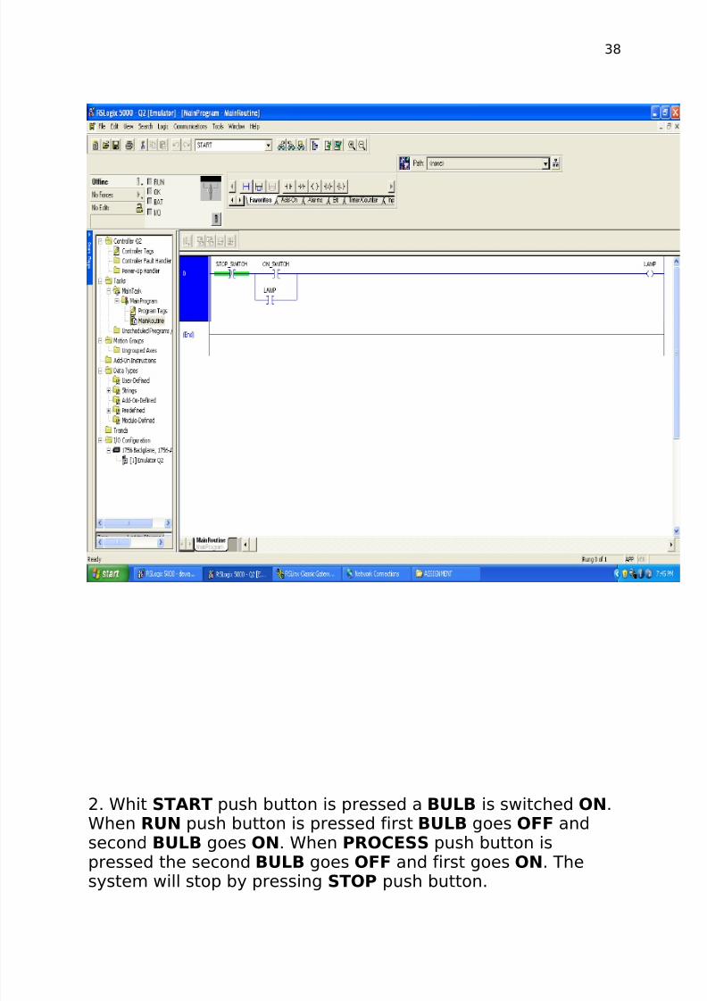
2. Whit START push button is pressed a BULB is switched ON.When RUN push button is pressed first BULB goes OFF andsecond BULB goes ON. When PROCESS push button ispressed the second BULB goes OFF and first goes ON. The
system will stop by pressing STOP push button.

8/7/2019 INDUSTRIAL FILE
http://slidepdf.com/reader/full/industrial-file 39/64
39
3.There are three lamps, first lamp should go ON when STARTpush button is pressed, when again the same push button ispressed first lamp should go OFF and second lamp shouldswitch ON, when again the same push button is pressed the
second lamp should go OFF and third should go ON, whenagain the same push button is pressed the third lamp go OFF

8/7/2019 INDUSTRIAL FILE
http://slidepdf.com/reader/full/industrial-file 40/64
40
and again the first lamp goes ON. The system will stop bypressing the OFF push button.
4. When START toggle switch is pressed a lamp should go ON for10second, after 10 second the lamp should go OFF while theSTART toggle switch is ON.

8/7/2019 INDUSTRIAL FILE
http://slidepdf.com/reader/full/industrial-file 41/64
41
5. A lamp should go ON after 10second of pressing the STARTpush button and it will go OFF by pressing the STOP pushbutton.

8/7/2019 INDUSTRIAL FILE
http://slidepdf.com/reader/full/industrial-file 42/64
42
6. A high to low pulse is generated after every 10second of pressing START push button.

8/7/2019 INDUSTRIAL FILE
http://slidepdf.com/reader/full/industrial-file 43/64
43
7. There are two lamps, the first lamp should go ON for 10secondby pressing the START push button, after 10second the firstlamp should go OFF and the second lamp should go ON. TheON bulb should go OFF on pressing STOP push button.

8/7/2019 INDUSTRIAL FILE
http://slidepdf.com/reader/full/industrial-file 44/64
44
8. There are two lamps, on pressing the START push buttonfirst lamp should go ON and when start push button ispressed again the first lamp goes OFF and second lampshould go ON. If any lamp is ON for more than 15secondthen both the lamps will interchange their status i.e. the ONlamp goes OFF and OFF lamp goes ON. The process willstop by pressing the STOP push button.

8/7/2019 INDUSTRIAL FILE
http://slidepdf.com/reader/full/industrial-file 45/64
45
SCADAINTRODUCTION:
SCADA stands for supervisory control and dataacquisition.

8/7/2019 INDUSTRIAL FILE
http://slidepdf.com/reader/full/industrial-file 46/64
46
SCADA is the Software tool in which you can able toview/Monitor/Control your Process Variable data andGraphical representation of your plant etc. It's anoperator front end display. Example of few SCADA S/W is
Wonderware, IFix, RS View, WinCC etc.
SCADA is a software used to gather data from fieldinstruments with the help of DCS or PLC depending onthe applications by the server and making it available inanimated form. This is usually found in control rooms.
This is a software that control two or more PLCs.
SCADA SUBSYSTEM
1. A Human-Machine Interface or HMI is the apparatuswhich presents process data to a human operator, andthrough this, the human operator monitors and controlsthe process.
2. A supervisory (computer) system, gathering(acquiring) data on the process and sending commands(control) to the process.
3. Remote Terminal Units (RTUs) connecting to sensors inthe process, converting sensor signals to digital data andsending digital data to the supervisory system.
4. Programmable Logic Controller (PLCs) used as fielddevices because they are more economical, versatile,flexible, and configurable than special-purpose RTUs.
5. Communication infrastructure connecting thesupervisory system to the Remote Terminal Units.
RSView32
It is a ROCKWELL software for SCADA.

8/7/2019 INDUSTRIAL FILE
http://slidepdf.com/reader/full/industrial-file 47/64
47
It is an integrated windows based software, used tocontrol and monitor automation machines andprocesses.
This software is divided into two packages:
1. RSView32 Works Software2. RSView32 Runtime Software
1. RSView32 Works Software:Contains editors for developing an entire project it alsodevelops software for running graphic displays of anoperation.
2. RSView32 Runtime Software:
Contains a subset of editor for editing certain parts of aproject.
PROJECT CREATION
RSView32 Project:A set of files created in RSView32 Software that
are
used to automate an industrial process to enablean
operator to control and monitor an operation.RSView32 Software initially creates a folder with
thename of the project.
• Activity Log:Contains activity log files.
• Project Name:Can be up to 255 characters.The RSView32 project file has .rsv.
• Project Manager:Contains the tools or the editors for creating andediting the components that make up a project.
The
project manager is divided into two panes:

8/7/2019 INDUSTRIAL FILE
http://slidepdf.com/reader/full/industrial-file 48/64
48
1. Left Pane:Contains following five folders, which containeditors to create and configure project
components.a) Systemb) Graphicsc) Alarmsd) Data Loge) Logic and Control
2. Right Pane:Displays the project components.
CONFIGURING AN RSView32 PROJECT
It is used to enable a programmer to control or monitor anoperation. A computer with RSView32 Software installedconnects to other communication devices using followingcomponents:
1. Communication Device2. Communication Channel3. Network4. Node5. Communication Driver
1. Communication Device:

8/7/2019 INDUSTRIAL FILE
http://slidepdf.com/reader/full/industrial-file 49/64
49
Hardware device that connect the communicationchannel to
RSView32 station.
2. Communication Channel:Link that sends data between an RSView32 station and
one ormore processor on a network.
3. Network:Group of devices that are connected by a medium forCommunications such as a cable systems.
4. Node:Physical device, such as processor, computer etc on acommunication network.
5. Communication Driver:The communication driver is the software that permits
theComputer to communicate with the communication
device.
For communication with most Allen–Bradleyprogrammable

8/7/2019 INDUSTRIAL FILE
http://slidepdf.com/reader/full/industrial-file 50/64
50
controllers, use RSLinx.
GRAPHICS DISPLAY A graphic display represents the operator’s view of plant
activity. The display can show system or process data andprovide operators with a way to write values to an externaldevice such as a programmable controller. Operators can alsoprint the display at runtime to create a visual record of tagvalues.
GRAPHICS DISPLAY EDITOR To open the Graphic Display editor:1. In the Project Manager, open the Graphics folder.
2. Open the Graphic Display editor by doing one of thefollowing:
• double–click the Display icon
• right–click the Display icon and then click New
The editor’s main components The figure below shows the main components of the GraphicDisplay editor. Each component is briefly described in the tableon the following page.

8/7/2019 INDUSTRIAL FILE
http://slidepdf.com/reader/full/industrial-file 51/64
51
To rotate an object:

8/7/2019 INDUSTRIAL FILE
http://slidepdf.com/reader/full/industrial-file 52/64
52
1. Click the Rotate tool.2. Click the mouse button. A small circle with a crosshairappears.
This is the anchor point that is used as the center of rotation.
To move the center of rotation, drag the crosshair.3. Place the pointer on an edge of the object and drag theobject to rotate it.
To rotate the object in five–degree increments, press Ctrl whileyou drag.4. When the object is in the desired position, release the mousebutton.
Types of graphic objects:
You can create the following types of objects:
Simple objects: geometric and freehand objects, and text.
These objects are created in the RSView32 Graphic Displayeditor.
Advanced objects: complex objects that typically require dataconfiguration.
OLE objects: objects such as spreadsheets, charts, or textproduced by other Windows applications. The types of OLEobjects that are available depend on the software installed onyour system.
ActiveX objects (formerly called OLE custom controls orOCXs): control objects such as gauges, sliders, and buttons,and objects you create yourself using a tool like Visual Basic
8/7/2019 INDUSTRIAL FILE
http://slidepdf.com/reader/full/industrial-file 53/64
53
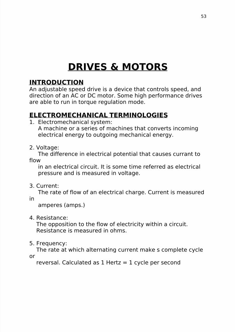
DRIVES & MOTORS
INTRODUCTIONAn adjustable speed drive is a device that controls speed, anddirection of an AC or DC motor. Some high performance drivesare able to run in torque regulation mode.
ELECTROMECHANICAL TERMINOLOGIES1. Electromechanical system:
A machine or a series of machines that converts incomingelectrical energy to outgoing mechanical energy.
2. Voltage:The difference in electrical potential that causes currant to
flowin an electrical circuit. It is some time referred as electrical
pressure and is measured in voltage.
3. Current:The rate of flow of an electrical charge. Current is measured
inamperes (amps.)
4. Resistance:The opposition to the flow of electricity within a circuit.
Resistance is measured in ohms.
5. Frequency:The rate at which alternating current make s complete cycle
orreversal. Calculated as 1 Hertz = 1 cycle per second

8/7/2019 INDUSTRIAL FILE
http://slidepdf.com/reader/full/industrial-file 54/64
54
DC Drives
DC Drive Control SystemA basic DC drive control system generally contains a drivecontroller and DC motor.
The controls allow the operator to start, stop, and changedirection and speed of the motor by turning potentiometers or
other operator devices. These controls may be an integral partof the controller or may be remotely mounted. The drivecontroller converts a 3-phase AC voltage to an adjustable DCvoltage, which is then applied to a DC motor armature.
The DC motor converts power from the adjustable DC voltagesource to rotating mechanical force. Motor shaft rotation anddirection are proportional to the magnitude and polarity of theDC voltage applied to the motor. The tachometer (feedback
device) converts actual speed to an electrical signal that issummed with the desired reference signal. The output of thesumming junction provides an error signal to the controller anda speed correction is made.
DC Motors The following are the four basic types of DC motors and their
operating characteristics:

8/7/2019 INDUSTRIAL FILE
http://slidepdf.com/reader/full/industrial-file 55/64
55
Shunt WoundShunt-wound motors have the field controlled separately fromthe armature winding. With constant armature voltage andconstant field excitation, the shunt-wound motor offers
relatively flat speed-torque characteristics. The shunt-woundmotor offers simplified control for reversing, especially forregenerative drives.
Series Wound The series-wound motor has the field connected in series with
the armature. Although the series wound motor offers highstarting torque, it has poor speed regulation. Series-woundmotors are generally used on low speed, very heavy loads.
Compound Wound The compound-wound DC motor utilizes a field winding in
series with the armature in addition to the shunt field, to obtain

8/7/2019 INDUSTRIAL FILE
http://slidepdf.com/reader/full/industrial-file 56/64
56
a compromise in performance between a series and a shuntwound type motor. The compound-wound motor offers acombination of good starting torque and speed stability.
Permanent Magnet The permanent magnet motor has a conventional woundarmature with commutator and brushes. Permanent magnetsreplace the field windings. This type of motor has excellentstarting torque, with speed regulation slightly less than that of the compound motor. Peak starting torque is commonly limited
to 150% of rated torque to avoid demagnetizing the field poles. Typically these are low horsepower.
Armature voltage controlled DC drives are capable of providingrated current and torque at any speed between zero and thebase (rated) speed of the motor. These drives use a fixed field

8/7/2019 INDUSTRIAL FILE
http://slidepdf.com/reader/full/industrial-file 57/64
57
supply and give motor characteristics. The motor outputhorsepower is directly proportional to speed (50% horsepowerat 50% speed).
The term constant torque describes a load type where thetorque requirement is constant over the speed range.Horsepower at any given operating point can be calculated withthe following equation:
Where:
Torque is measured in Lb-FtSpeed is measured in RPM.

8/7/2019 INDUSTRIAL FILE
http://slidepdf.com/reader/full/industrial-file 58/64
58
pulse width modulated “PWM” technique. With this method, aDC voltage is applied to the motor windings in time controlled
pulses in order to achieve current that approximates a sinewave of the desired frequency. IGBTs or Isolated Gate Bipolar
Transistors are the latest technology and offer the ability toswitch the PWM pulses very fast. This allows several thousandpulses to be applied in one cycle of the applied motorfrequency. More pulses in a given cycle result in a smoothercurrent waveform and better motor performance.
AC Motor TypesAC motors can be divided into two main types: induction andsynchronous. Induction motors are most common in industry.Synchronous motors are special purpose motors that do notrequire any slip and operate at synchronous speed.
The induction motor is the simplest and most rugged of allelectric motors. The induction motor is generally classified by aNEMA design category. Before a meaningful discussion onNEMA type motors can be had, we should first look at what
makes up a torque speed curve.

8/7/2019 INDUSTRIAL FILE
http://slidepdf.com/reader/full/industrial-file 59/64
59
Anatomy of a Speed Torque CurveGenerally speaking the following can be said about a speedtorque curve when starting across the line. Starting torque is
usually around 200% even though current is at 600%. This iswhen slip is the greatest. (Starting torque is also called BlockedRotor Torque, Locked Rotor Torque or Breakaway Torque.) Sucha large inrush of current may cause the supply voltage to dipmomentarily, affecting other equipment connected to the samelines. To prevent this, large motors will connect extra resistorsto inductors in series with the stator during starting. Extraprotective devices are also required to remove the motor fromthe supply lines if an excessive load causes a stalled condition.
As the motor begins to accelerate, the torque drops off,reaching a minimum value, called Pull-up Torque, between 25-
40% of synchronous speed (Point B). Pull-up Torque is causedby harmonics that result from the stator windings being

8/7/2019 INDUSTRIAL FILE
http://slidepdf.com/reader/full/industrial-file 60/64
60
concentrated in slots. If the windings are uniformly distributedaround the stator periphery, Pull-up Torque is greatly reduced.Some motor design curves show no actual Pull-up Torque andfollow the dashed line between points A and C.
As acceleration continues, rotor frequency and inductivereactance decrease. The rotor flux moves more in phase withthe stator flux and torque increases. Maximum Torque (orBreakdown Torque) is developed at point C where inductivereactance becomes equal to the rotor resistance.
Beyond point C, (points D, E and F) the inductive reactancecontinues to drop off but rotor current also decreases at thesame rate, reducing torque.
Point G is synchronous speed and proves that if rotor and statorare at the same speed, rotor current and torque are zero.
At running speed, the motor will operate between points F andD, depending on load. However temporary load surges maycause the motor to slip all the way back near point C on the“knee” of the curve.
Beyond point C, the power factor decreases faster than current
increases causing torque to drop off. On the linear part of themotor curve (points C to G), rotor frequency is only 1 to 3 hertz– almost DC. Inductive reactance is essentially zero and rotorpower factor approaches unity.
Torque and current now become directly proportional – 100%current produces 100% torque. If a 1HP motor has a nameplatecurrent of 3.6 amps, then when it draws 3.6 amps (at propervoltage and frequency) it must be producing 100% of itsnameplate torque. Torque and current remain directlyproportional up to approximately 10% slip.
Notice that as motor load increases from zero (point F) to 100%(point E), the speed drops only 45-55 RPM, about 3% of synchronous speed. This makes the squirrel cage inductionmotor very suitable for most constant speed applications (suchas conveyors) where, in some cases, 3% speed regulationmight be acceptable. If better speed regulation is required, thesquirrel cage motor may be operated from a closed loop

8/7/2019 INDUSTRIAL FILE
http://slidepdf.com/reader/full/industrial-file 61/64
61
regulator such as a Rockwell Automation variable frequencydrive.
The locked rotor torque and current, breakdown torque, pull-up
torque and the percent slip, determine the classifications forNEMA design motors. The speed-torque curve andcharacteristics of each design are as follows:
Design A — motors have a low resistance, low inductance rotorproducing low starting torque and high breakdown torque. Thelow resistance characteristic causes starting current to be high.It is a high efficiency design; therefore the slip is usually 3% orless.
Design B — motors have a higher impedance rotor producing aslightly higher starting torque and lower current draw. For thisreason, design B motors are a general-purpose type motor andaccount for the largest share of induction motors sold. The slipof a Design B motor is approximately 3-5% or less.
8/7/2019 INDUSTRIAL FILE
http://slidepdf.com/reader/full/industrial-file 62/64
62
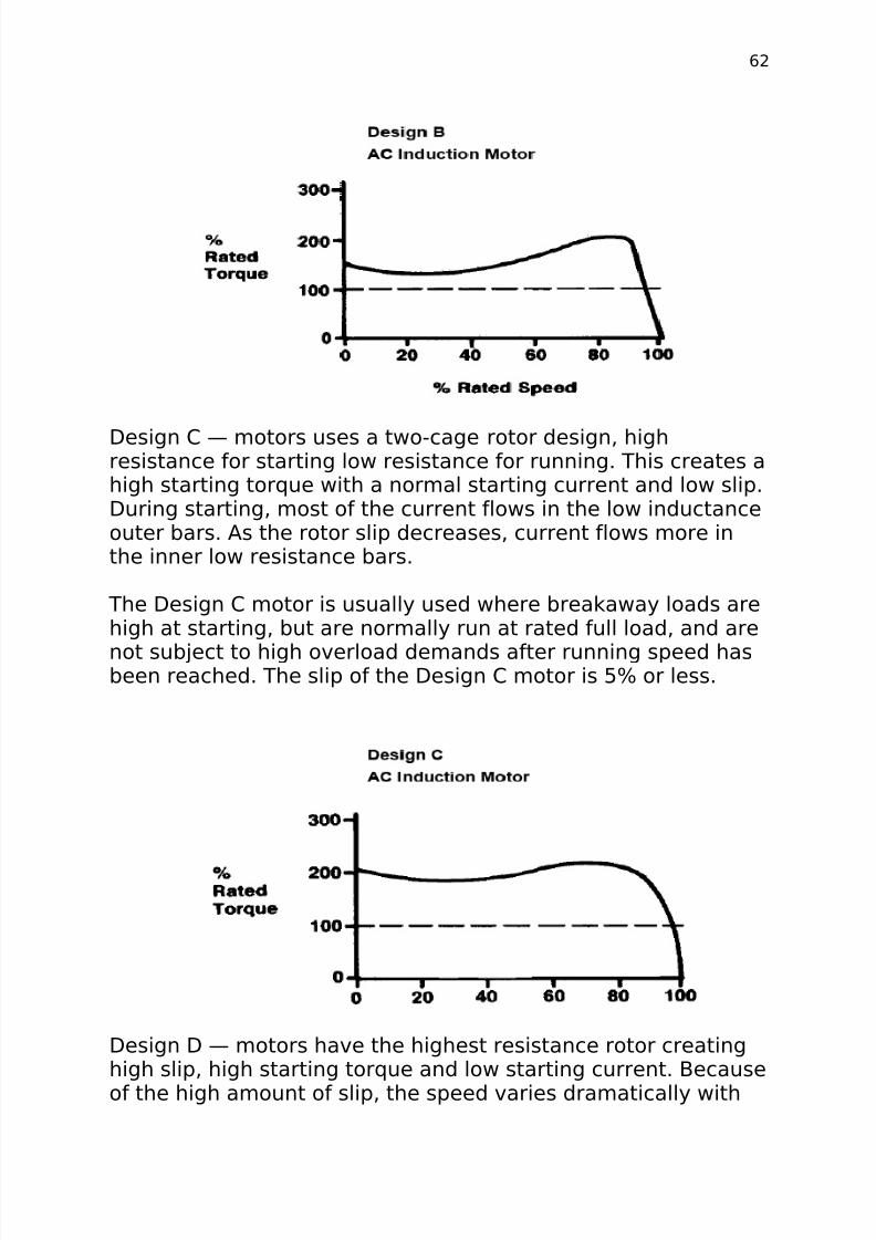
Design C — motors uses a two-cage rotor design, highresistance for starting low resistance for running. This creates ahigh starting torque with a normal starting current and low slip.During starting, most of the current flows in the low inductanceouter bars. As the rotor slip decreases, current flows more inthe inner low resistance bars.
The Design C motor is usually used where breakaway loads arehigh at starting, but are normally run at rated full load, and are
not subject to high overload demands after running speed hasbeen reached. The slip of the Design C motor is 5% or less.
Design D — motors have the highest resistance rotor creatinghigh slip, high starting torque and low starting current. Because
of the high amount of slip, the speed varies dramatically with

8/7/2019 INDUSTRIAL FILE
http://slidepdf.com/reader/full/industrial-file 63/64
63
load. The slip of this type motor is approximately 5 to 8%. Thishigh slip characteristic relates to a low efficiency design and amotor that runs hot.
Synchronous MotorsSynchronous motors operate at synchronism with the linefrequency and maintain a constant speed regardless of loadwithout sophisticated electronic control. The two most commontypes of synchronous motors are reluctance and permanentmagnet. The synchronous motor typically provides up to amaximum of 140% of rated torque. These designs start like aninduction motor but quickly accelerate from approximately 90%sync speed to synchronous speed. When operated from an acdrive they require boost voltage to produce the required torqueto synchronize quickly after power application.

8/7/2019 INDUSTRIAL FILE
http://slidepdf.com/reader/full/industrial-file 64/64
64
Also available in high horsepower motors is the separatelyexcited synchronous motor. This design requires a LoadCommutated Inverter (LCI) which is not presently availablefrom Allen- Bradley.