Embed Size (px)
Citation preview

Cover
Industrial Ethernet Communication: Data Exchange S7-200 <-> S7-1200
SIMATIC S7 -1200
Configuration Example X20 October 2010
Applications & Tools
Answers for industry.

Warranty, Liability and Support
S7 Communication: Data Exchange S7-200 <-> S7-1200 V1.0, Entry ID: 40622389 2
Warranty, Liability and Support Note The application examples are not binding and do not claim to be complete
regarding configuration, equipment and any eventuality. The application examples do not represent customer-specific solutions. They are only intended to provide support for typical applications. You are responsible for ensuring that the described products are used correctly. These application examples do not relieve you of the responsibility to use sound practices in application, installation, operation and maintenance. When using these Application Examples, you recognize that we cannot be made liable for any damage/claims beyond the liability clause described. We reserve the right to make changes to these Application Examples at any time without prior notice. If there are any deviations between the recommendations provided in these application examples and other Siemens publications – e.g. Catalogs – the contents of the other documents have priority.
We accept no liability for information contained in this document. Any claims against us – based on whatever legal reason – resulting from the use of the examples, information, programs, engineering and performance data etc., described in this Application Example shall be excluded. Such an exclusion shall not apply in the case of mandatory liability, e.g. under the German Product Liability Act (“Produkthaftungsgesetz”), in case of intent, gross negligence, or injury of life, body or health, guarantee for the quality of a product, fraudulent concealment of a deficiency or breach of a condition which goes to the root of the contract (“wesentliche Vertragspflichten”). However, claims arising from a breach of a condition which goes to the root of the contract shall be limited to the foreseeable damage which is intrinsic to the contract, unless caused by intent or gross negligence or based on mandatory liability for injury of life, body or health. The above provisions do not imply a change in the burden of proof to your detriment. It is not permissible to transfer or copy these Application Examples or excerpts thereof without express authorization from Siemens Industry Sector. If you have any questions about this document, please contact us at the following e-mail address: [email protected]
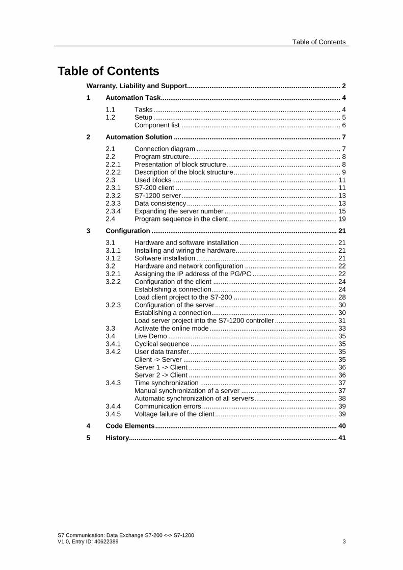
Table of Contents
S7 Communication: Data Exchange S7-200 <-> S7-1200 V1.0, Entry ID: 40622389 3
Table of Contents Warranty, Liability and Support.................................................................................. 2 1 Automation Task................................................................................................ 4
1.1 Tasks.................................................................................................... 4 1.2 Setup .................................................................................................... 5
Component list ..................................................................................... 6 2 Automation Solution ......................................................................................... 7
2.1 Connection diagram ............................................................................. 7 2.2 Program structure................................................................................. 8 2.2.1 Presentation of block structure............................................................. 8 2.2.2 Description of the block structure......................................................... 9 2.3 Used blocks........................................................................................ 11 2.3.1 S7-200 client ...................................................................................... 11 2.3.2 S7-1200 server................................................................................... 13 2.3.3 Data consistency ................................................................................ 13 2.3.4 Expanding the server number ............................................................ 15 2.4 Program sequence in the client.......................................................... 19
3 Configuration ................................................................................................... 21 3.1 Hardware and software installation .................................................... 21 3.1.1 Installing and wiring the hardware...................................................... 21 3.1.2 Software installation ........................................................................... 21 3.2 Hardware and network configuration ................................................. 22 3.2.1 Assigning the IP address of the PG/PC ............................................. 22 3.2.2 Configuration of the client .................................................................. 24
Establishing a connection................................................................... 24 Load client project to the S7-200 ....................................................... 28
3.2.3 Configuration of the server................................................................. 30 Establishing a connection................................................................... 30 Load server project into the S7-1200 controller ................................. 31
3.3 Activate the online mode.................................................................... 33 3.4 Live Demo .......................................................................................... 35 3.4.1 Cyclical sequence .............................................................................. 35 3.4.2 User data transfer............................................................................... 35
Client -> Server .................................................................................. 35 Server 1 -> Client ............................................................................... 36 Server 2 -> Client ............................................................................... 36
3.4.3 Time synchronization ......................................................................... 37 Manual synchronization of a server ................................................... 37 Automatic synchronization of all servers............................................ 38
3.4.4 Communication errors ........................................................................ 39 3.4.5 Voltage failure of the client................................................................. 39
4 Code Elements................................................................................................. 40 5 History............................................................................................................... 41
Automation TaskTasks
S7 Communication: Data Exchange S7-200 <-> S7-1200 V1.0, Entry ID: 40622389 4
Cop
yrig
ht ©
Sie
men
s A
G 2
010
All
right
s re
serv
ed
4062
2389
_CE
-X20
_v1d
0_en
.doc
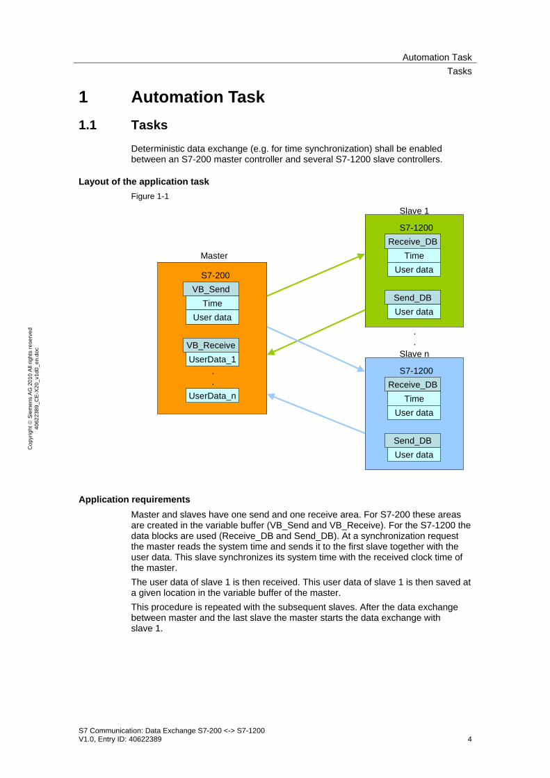
1 Automation Task 1.1 Tasks
Deterministic data exchange (e.g. for time synchronization) shall be enabled between an S7-200 master controller and several S7-1200 slave controllers.
Layout of the application task Figure 1-1
S7-200VB_Send
VB_Receive
TimeUser data
UserData_1
UserData_n
.
.
S7-1200
Send_DB
Receive_DBTime
User data
User data
S7-1200
Send_DB
Receive_DBTime
User data
User data
Master
Slave 1
Slave n
.
.
Application requirements Master and slaves have one send and one receive area. For S7-200 these areas are created in the variable buffer (VB_Send and VB_Receive). For the S7-1200 the data blocks are used (Receive_DB and Send_DB). At a synchronization request the master reads the system time and sends it to the first slave together with the user data. This slave synchronizes its system time with the received clock time of the master. The user data of slave 1 is then received. This user data of slave 1 is then saved at a given location in the variable buffer of the master. This procedure is repeated with the subsequent slaves. After the data exchange between master and the last slave the master starts the data exchange with slave 1.

Automation TaskSetup
S7 Communication: Data Exchange S7-200 <-> S7-1200 V1.0, Entry ID: 40622389 5
Cop
yrig
ht ©
Sie
men
s A
G 2
010
All
right
s re
serv
ed
4062
2389
_CE
-X20
_v1d
0_en
.doc
1.2 Setup
For data transfer via Industrial Ethernet the SIMATIC S7-200 provides the expansion modules Ethernet-CP 243-1 and Internet-CP 243-1 IT. The real-time cock is supported by the S7-200 as follows: Table 1-1
CPU Real-time clock
221 222
Optimal plug-in module (6ES7297-1AA23-0XA0)
224 224XP/224XPsi
226
Integrated
The automation task is demonstrated at the example of data exchange between a CPU 224 with Ethernet CP 243-1 as a master and two slave S7-1200 controllers (slave 1 and slave 2).
Schematic layout Figure 1-2
STEP 7Basic V10.5
9STEP 7-Micro/WIN
10
CPU 1212CPM 1207
5 6
CPU 1214CPM 1207
5 7
CSM 1277
4
8
IP address:192.168.0.1
IP address:192.168.0.2
IP address:192.168.0.3
IP address:192.168.0.241
CPU 224 CP 243-1
2 31
LOGO!POWER
11
Master Slave 1
Slave 2
Figure 1-2 shows the principal setup. The communicating CPUs as well as the programming device with the software “STEP 7 Basic V10.5” for programming the S7-1200 and “STEP 7-Micro/WIN” for programming the S7-200, are each connected with the CSM 1277 switch via Ethernet cable. Configuring the Ethernet CPs 243-1 requires an additional connection (i.e. via the USB/PPI cable) between PG and CPU 224.

Automation TaskSetup
S7 Communication: Data Exchange S7-200 <-> S7-1200 V1.0, Entry ID: 40622389 6
Cop
yrig
ht ©
Sie
men
s A
G 2
010
All
right
s re
serv
ed
4062
2389
_CE
-X20
_v1d
0_en
.doc
Component list Table 1-2
No. Component Qty. MLFB / order number
1. LOGO!POWER 24V / 5A 1 6EP1331-1SH02 2. CPU224, DC PS, 14DE DC/10DA DC 1 6ES7214-1AD23-0XB0 3. COMMUNICATION PROCESSOR CP 243-1 1 6GK7243-1EX00-0XE0 4. COMPACT SWITCH MODULE CSM 1277 1 6GK7277-1AA00-0AA0 5. POWER SUPPLY S7-1200 PM1207 2 6EP1332-1SH71 6. S7-1200 CPU1212C 1 6ES7212-1AD30-0XB0 7. S7-1200 CPU1214C 1 6ES7214-1AE30-0XB0 8. PC/PG 1 9. STEP7-MICRO/WIN V4.0 1 6ES7810-2CC03-0YX0 10. STEP 7 BASIC V10.5 1 6ES7822-0AA00-0YA0 11. S7-200, USB/PPI CABLE 1 6ES7901-3DB30-0XA0 12. STEP 7 Micro/WIN V4.0 Service Pack (SP7) 1 Entry ID: 3300523213. STEP 7 Basic V10.5 Service Pack 2 1 Entry ID:39741113
Automation SolutionConnection diagram
S7 Communication: Data Exchange S7-200 <-> S7-1200 V1.0, Entry ID: 40622389 7
Cop
yrig
ht ©
Sie
men
s A
G 2
010
All
right
s re
serv
ed
4062
2389
_CE
-X20
_v1d
0_en
.doc
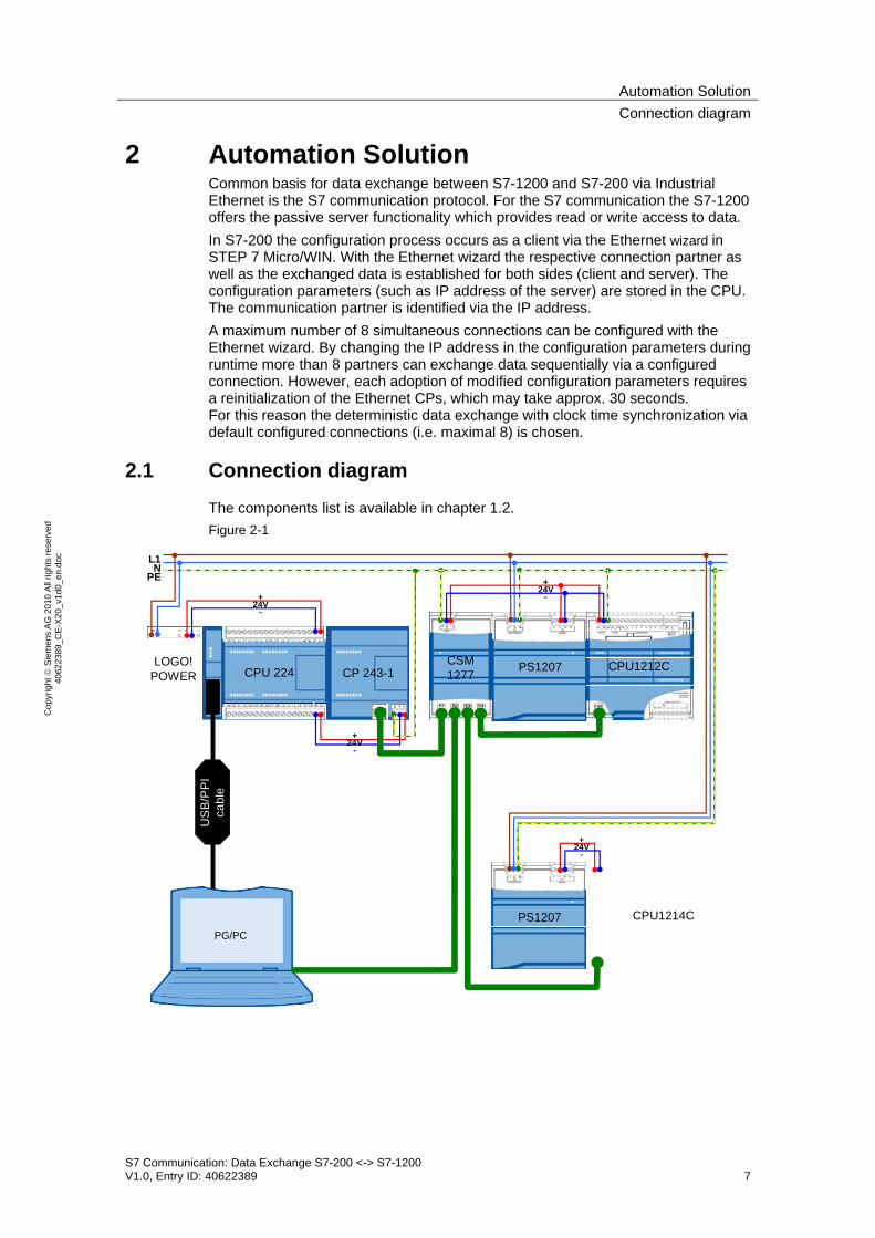
2 Automation Solution Common basis for data exchange between S7-1200 and S7-200 via Industrial Ethernet is the S7 communication protocol. For the S7 communication the S7-1200 offers the passive server functionality which provides read or write access to data. In S7-200 the configuration process occurs as a client via the Ethernet wizard in STEP 7 Micro/WIN. With the Ethernet wizard the respective connection partner as well as the exchanged data is established for both sides (client and server). The configuration parameters (such as IP address of the server) are stored in the CPU. The communication partner is identified via the IP address. A maximum number of 8 simultaneous connections can be configured with the Ethernet wizard. By changing the IP address in the configuration parameters during runtime more than 8 partners can exchange data sequentially via a configured connection. However, each adoption of modified configuration parameters requires a reinitialization of the Ethernet CPs, which may take approx. 30 seconds. For this reason the deterministic data exchange with clock time synchronization via default configured connections (i.e. maximal 8) is chosen.
2.1 Connection diagram
The components list is available in chapter 1.2. Figure 2-1
US
B/P
PI
cabl
e
L1N
PE +24V
-
PG/PC
PS1207CSM1277
CPU1212C
PS1207 CPU1214C
+24V
-
LOGO!POWER CP 243-1CPU 224
+24V
-
+24V
-

Automation SolutionProgram structure
S7 Communication: Data Exchange S7-200 <-> S7-1200 V1.0, Entry ID: 40622389 8
Cop
yrig
ht ©
Sie
men
s A
G 2
010
All
right
s re
serv
ed
4062
2389
_CE
-X20
_v1d
0_en
.doc
2.2 Program structure
This chapter describes the program structure of the example on the function and data block level of the automation system.
2.2.1 Presentation of block structure
Figure 2-2 and Figure 2-3 show the call hierarchy of the used subprograms/blocks as well as the access to the used data areas or data blocks for the S7-200 client and the S7-1200 server. Figure 2-2
SBR0“Client_1200”
SBR1“ETH0_CTRL”
M_IDSYNCTUser_data
VB1000 “SEND_Struct”
DB1 ”VB”
M_IDsynchronizedUser_data
VB1100 “RCV_Struct_1”
VB1200 “RCV_Struct_2”
sync_byte
.
.
.
S7-200
OB1“MAIN”
SBR2“ETH0_XFR”
Chan_IDData
SBR2“ETH0_XFR”
Chan_IDData
index0
index1
SBR3“Pointer”
IndexindexOut synchronized
VB0 “STATUS_Struct”
Server: 87654321
VB2000 “ETH0_DATA”...
M_ID_unequal
Figure 2-3
S7-1200
OB1“MAIN”
M_IDsync_CLKREAD_CLK_CDTUser_data
DB1201 ”Receive_DB”
M_IDsynchronizedUser_data
DB1202 ”Send_DB”
FC1200“DnT_DTL”
DB1200“Data_DB”
“WR_SYS_T”

Automation SolutionProgram structure
S7 Communication: Data Exchange S7-200 <-> S7-1200 V1.0, Entry ID: 40622389 9
Cop
yrig
ht ©
Sie
men
s A
G 2
010
All
right
s re
serv
ed
4062
2389
_CE
-X20
_v1d
0_en
.doc
2.2.2 Description of the block structure
S7-200 has only one data block (“DB1”) which stores all the variables. DB1 contains: Table 2-1
Variable buffer area Description
VB 0 – VB 23 Status and monitoring information
VB 1000 – VB 1099 Send data VB 1100 – VB 1199 Receive data of server 1 VB 1200 – VB 1299 Receive data of server 2 VB 2000 – VB 2268 Configuration data of the Ethernet wizard
Amongst other things the status and monitoring information contain the synchronization byte “sync_byte”. Each bit of this byte contains the synchronization request for on of the maximal 8 servers to be synchronized. OB1 cyclically calls the subprogram SBR0 “Client_1200”. The control block “ETH0_CTRL” generated by the Ethernet wizard is called cyclically by the “Client_1200” and accesses the configuration data. In the SBR0 “Client_1200” the system time “T” is read cyclically and compared with a synchronization time which is given daily. If it agrees the synchronization request bits of all servers are set. The clock synchronization can also be executed individually for each server via the status table. Setting the synchronization request bit of the first S7-1200 server in the synchronization byte “sync_byte” causes setting the synchronization request “SYNC“ in the send data. Sub-program ETH0_XFR causes the CP 243-1 to transfer the send data to the DB1201 “Receive_DB” of the first server (defined by the “index” variable) (“Data” = “1”). Apart from the clock time synchronization information, “User_data” and a message ID “M_ID” are also transferred. OB1 “MAIN” of the server calls the FC1200 “DnT_DTL” function for the synchronization request “sync_CLK”. It transforms the clock time of the S7-200 client “T” of “DATE_AND_TIME” type into data type “DTL”. All variables are stored in DB1200 “Data_DB”. The transformed time is written to the system time of the S7-1200 via the “WR_SYS_T” function. After successful clock synchronization the “synchronized” bit is set in the send DB1202 “Send_DB”. The received message ID “M_ID” from DB1201 “Receive_DB” is mirrored to the send data block DB1202 “Send_DB”. After the data has been transferred to the server using subprogram ETH0_XFR (“Data” = “1”) the content of send data block DB1202 “Send_DB” is called again by the first server using subprogram ETH0_XFR (“Data” = “0”) and written to the preconfigured receive buffer (represented as “RCV_STRUCT_1”) in the variable buffer VB1100 – VB1199. Using the subprogram SBR3 “Pointer” and depending on the respective server (“index”) the received message ID “M_ID” is read from its receive data and compared with the sent data. Any deviation is stored in variable “M_ID_unequal”. In byte “M_ID_unequal” each bit corresponds to one of the maximal 8 servers equivalent to the synchronization byte.

Automation SolutionProgram structure
S7 Communication: Data Exchange S7-200 <-> S7-1200 V1.0, Entry ID: 40622389 10
Cop
yrig
ht ©
Sie
men
s A
G 2
010
All
right
s re
serv
ed
4062
2389
_CE
-X20
_v1d
0_en
.doc
After successful synchronization of server 1 (signaled by the “synchronized” variable) the synchronization request bit 0 (for server 1) is reset in synchronization byte “sync_byte”. The message ID “M_ID” is increased and the data exchange with server 2 is handled in the same way.

Automation SolutionUsed blocks
S7 Communication: Data Exchange S7-200 <-> S7-1200 V1.0, Entry ID: 40622389 11
Cop
yrig
ht ©
Sie
men
s A
G 2
010
All
right
s re
serv
ed
4062
2389
_CE
-X20
_v1d
0_en
.doc
2.3 Used blocks
The following tables give an overview of the used blocks on the client and server side.
2.3.1 S7-200 client
Table 2-2
Object name
Symbolic name Description
OB1 MAIN Cyclic organization block SBR0 Client_1200 Subprogram for deterministic data exchange
with several S7-1200 servers using the Ethernet wizard
SBR3 Pointer Subprogram for value reading values of an integer via a pointer
SBR1 ETH0_CTRL Control subprogram for the Ethernet CP on slot 0 (generated by the Ethernet wizard)
SBR2 ETH0_XFR Ethernet wizard generated by the subprogram for sending data (parameter “Data” = “0”) or receiving data (“Data” = “1”)

Automation SolutionUsed blocks
S7 Communication: Data Exchange S7-200 <-> S7-1200 V1.0, Entry ID: 40622389 12
Cop
yrig
ht ©
Sie
men
s A
G 2
010
All
right
s re
serv
ed
4062
2389
_CE
-X20
_v1d
0_en
.doc
Client_1200 (SBR0) The subprogram for deterministic data exchange with several S7-1200 servers using the Ethernet wizard is called cyclically in OB1. Figure 2-4
As the only input the maximal number of servers “server_max” must be specified. A maximum number of 8 connections per Ethernet CP can be configured with the Ethernet wizard. The data exchange with the servers occurs sequentially depending on the “server” variable. The following variables provide configuration options of the SBR0 “Client_1200” via the initial value in the data block or via the status table: Table 2-3
Name Data type Description
hour Int Hour specification of the daily synchronization time (value range: 0 – 23)
minute Int Minute specification of the daily synchronization time (value range: 0 – 59)
Timeout Int Maximum wait time in 0.1s until the step chain in SBR0 is automatically switched further (default: 0.5 s)
Status information The following variables provide status information of the maximal 8 connected S7-1200 servers. Each bit represents information of a server (Bit0 = Server1 … Bit7 = Server8). Table 2-4
Name Data type Description
sync_byte Byte Clock synchronization request Timeout_byte Byte Maximum processing time exceeded M_ID_unequal Byte Sent and received M_ID unequal Ch_Ready Word The 1st byte specifies the connected server.

Automation SolutionUsed blocks
S7 Communication: Data Exchange S7-200 <-> S7-1200 V1.0, Entry ID: 40622389 13
Cop
yrig
ht ©
Sie
men
s A
G 2
010
All
right
s re
serv
ed
4062
2389
_CE
-X20
_v1d
0_en
.doc
2.3.2 S7-1200 server
Table 2-5
Object name
Symbolic name Description
OB1 Main Cyclic organization block FC1200 DnT_DTL Function for converting data type
“DATE_AND_TIME” into data type “DTL” DB1200 Data_DB Variable data block DB1201 Receive_DB Data block for received data from the client DB1202 Send_DB Data block for the send data to the client
2.3.3 Data consistency
Figure 2-5 illustrates the data exchange between client and both S7-1200 servers. Figure 2-5
S7-1200S7-200
ClientVB1000-VB1099
Server 1DB1201 Byte0 – DB1201 Byte99
VB1100-VB1199 DB1202 Byte0 – DB1202 Byte99
Write data
Read data
VB1200-VB1299
Server 2DB1201 Byte0 – DB1201 Byte99
DB1202 Byte0 – DB1202 Byte99
Client -> Server The send area of the client and the receive block of the server must have the same length and structure. In the application example they consist of 100 bytes and have the following structure: Table 2-6
Name Data type Description
M_ID Int Message ID SYNC Bool Clock synchronization request T DATE_AND_TIME or
array of 8 bytes Synchronization time of the master (S7-200)
User_data 88 bytes User data (S7-200 -> S7-1200)

Automation SolutionUsed blocks
S7 Communication: Data Exchange S7-200 <-> S7-1200 V1.0, Entry ID: 40622389 14
Cop
yrig
ht ©
Sie
men
s A
G 2
010
All
right
s re
serv
ed
4062
2389
_CE
-X20
_v1d
0_en
.doc
Server -> Client The client receive area for each server and the send block of the server must be identical. The receive areas and the send DB 1202 consist of 100 bytes and are structured as follows: Table 2-7
Name Data type Description
M_ID Int Mirrored message ID for acknowledgement synchronized Bool Clock synchronization acknowledgement User_data 96 bytes User data (S7-1200 -> S7-200)
The user data “User_data” can be changed individually. However, the data structure must be identical on the sending and receiving side. Data consistency is on the program side guaranteed by the sequential processing of the send and receive jobs. Due to the continued data exchange between client and servers the data consistency can only be provided for one cycle. Consistent data must therefore be written into the send data blocks by the user within one cycle or be read from the receive data blocks.
Automation SolutionUsed blocks
S7 Communication: Data Exchange S7-200 <-> S7-1200 V1.0, Entry ID: 40622389 15
Cop
yrig
ht ©
Sie
men
s A
G 2
010
All
right
s re
serv
ed
4062
2389
_CE
-X20
_v1d
0_en
.doc
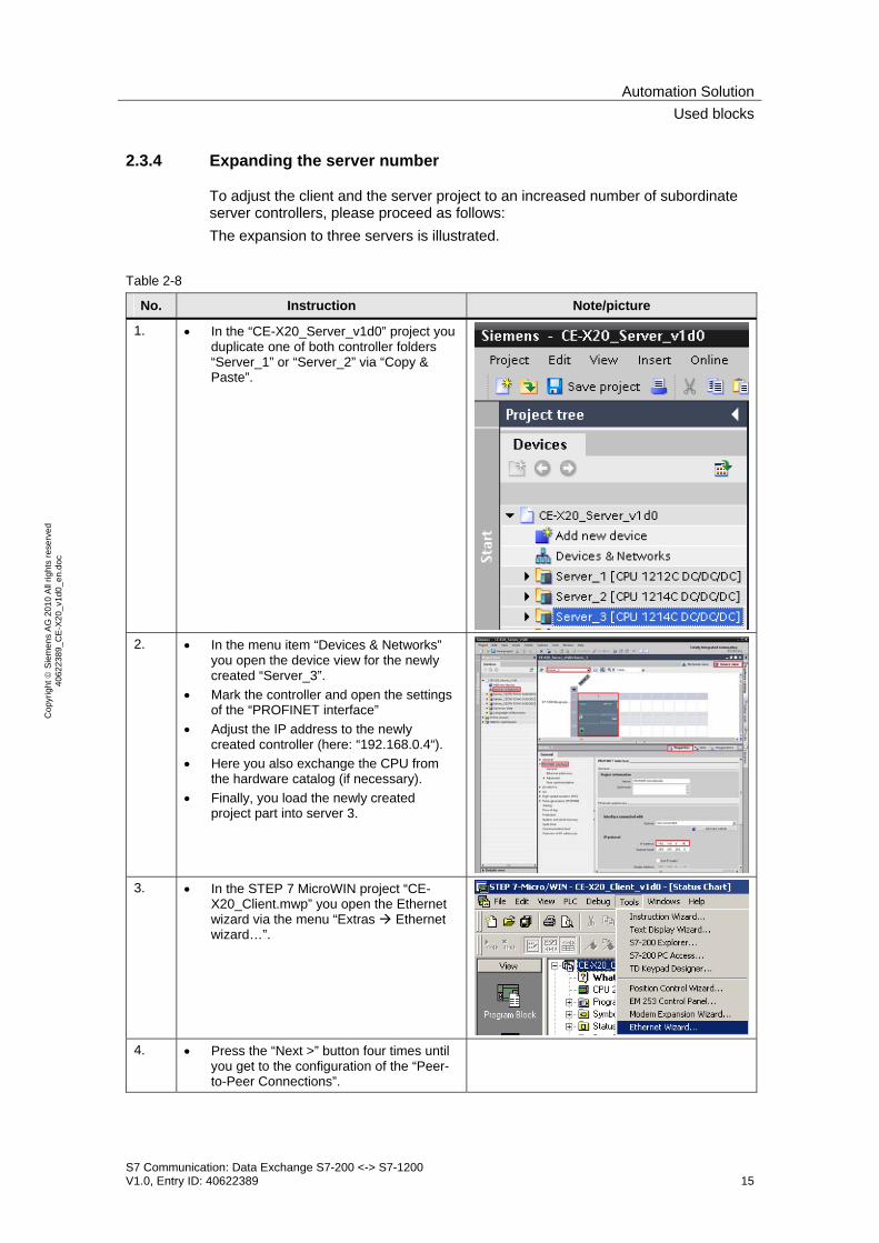
2.3.4 Expanding the server number
To adjust the client and the server project to an increased number of subordinate server controllers, please proceed as follows: The expansion to three servers is illustrated.
Table 2-8
No. Instruction Note/picture
1. • In the “CE-X20_Server_v1d0” project you duplicate one of both controller folders “Server_1” or “Server_2” via “Copy & Paste”.
2. • In the menu item “Devices & Networks”
you open the device view for the newly created “Server_3”.
• Mark the controller and open the settings of the “PROFINET interface”
• Adjust the IP address to the newly created controller (here: “192.168.0.4“).
• Here you also exchange the CPU from the hardware catalog (if necessary).
• Finally, you load the newly created project part into server 3.
3. • In the STEP 7 MicroWIN project “CE-
X20_Client.mwp” you open the Ethernet wizard via the menu “Extras Ethernet wizard…”.
4. • Press the “Next >” button four times until
you get to the configuration of the “Peer-to-Peer Connections”.
Automation SolutionUsed blocks
S7 Communication: Data Exchange S7-200 <-> S7-1200 V1.0, Entry ID: 40622389 16
Cop
yrig
ht ©
Sie
men
s A
G 2
010
All
right
s re
serv
ed
4062
2389
_CE
-X20
_v1d
0_en
.doc
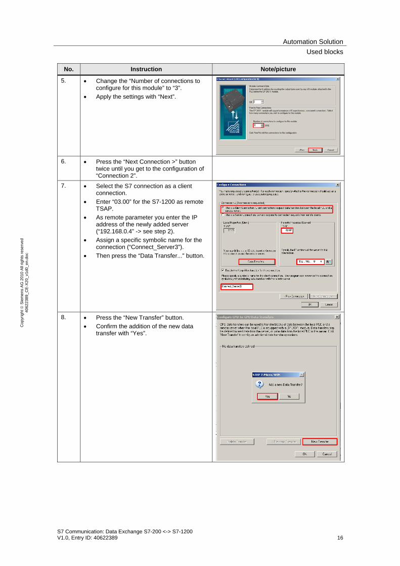
No. Instruction Note/picture
5. • Change the “Number of connections to configure for this module” to “3”.
• Apply the settings with “Next”.
6. • Press the “Next Connection >” button
twice until you get to the configuration of “Connection 2”.
7. • Select the S7 connection as a client connection.
• Enter “03.00” for the S7-1200 as remote TSAP.
• As remote parameter you enter the IP address of the newly added server (“192.168.0.4” -> see step 2).
• Assign a specific symbolic name for the connection (“Connect_Server3”).
• Then press the “Data Transfer...” button.
8. • Press the “New Transfer” button.
• Confirm the addition of the new data transfer with “Yes”.

Automation SolutionUsed blocks
S7 Communication: Data Exchange S7-200 <-> S7-1200 V1.0, Entry ID: 40622389 17
Cop
yrig
ht ©
Sie
men
s A
G 2
010
All
right
s re
serv
ed
4062
2389
_CE
-X20
_v1d
0_en
.doc
No. Instruction Note/picture
9. Create the data transmission to server 3 according to the transmissions to the other two servers: • Select the function “This data transfer
should: Write data to the remote server connection.”
• Please enter the number and start addresses of the data: – 100 data bytes – Local: VB1000 – Server: DB1201.DBB0
• Assign a symbolic name for the data transmission (“Write_Server3”).
• Press the “New Transfer...” button to read data from server 3.
• Confirm the addition of the new data transfer with “Yes”.
10. • Select the function “This data transfer
should: Read data from the remote server connection.”
• Please enter the number and start addresses of the data: – 100 data bytes – Local: VB1300 – Server: DB1202.DBB0
• Assign a symbolic name for the data transmission (“Read_Server3”).
• Click “OK” twice to accept the configured data transfer.
11. • Pres the “Next>” button twice.
12. • Press the “Finish” button and confirm the termination of the Ethernet wizard with “Yes”.
Automation SolutionUsed blocks
S7 Communication: Data Exchange S7-200 <-> S7-1200 V1.0, Entry ID: 40622389 18
Cop
yrig
ht ©
Sie
men
s A
G 2
010
All
right
s re
serv
ed
4062
2389
_CE
-X20
_v1d
0_en
.doc
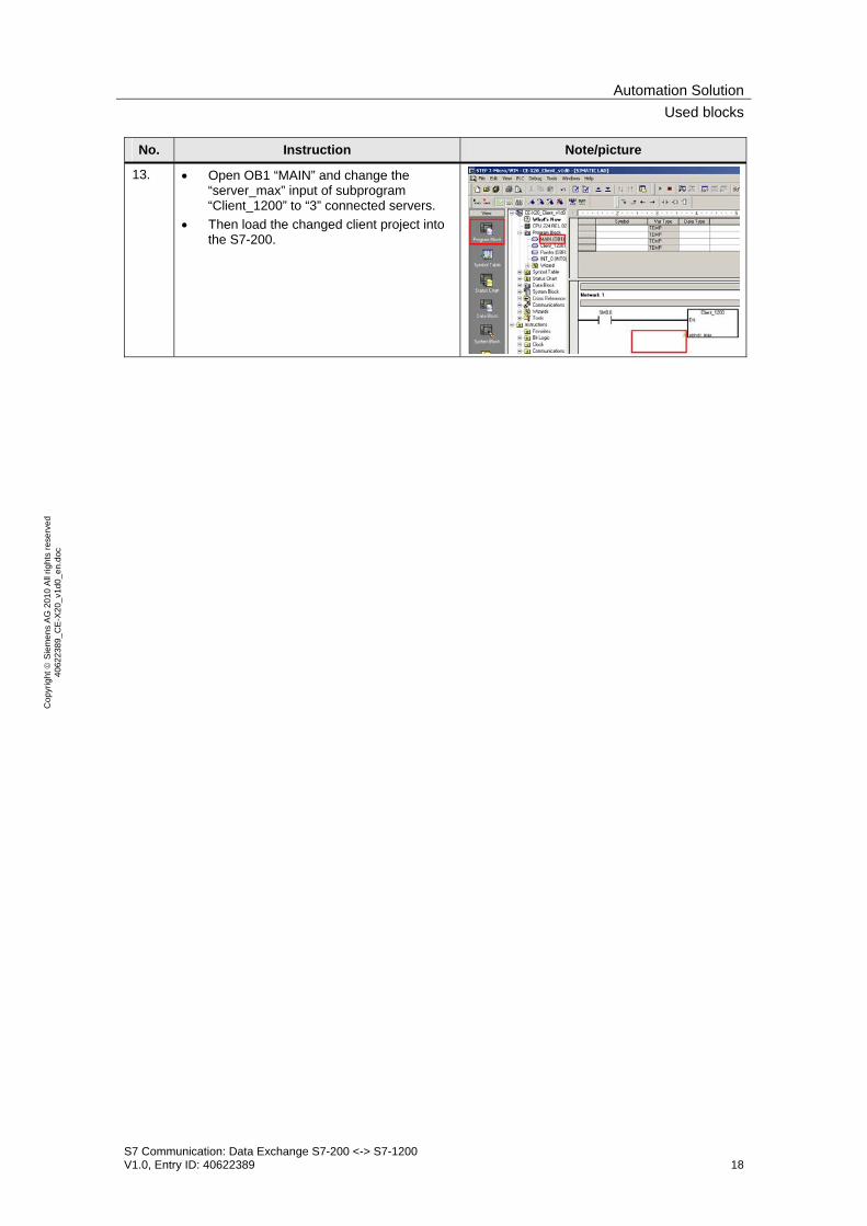
No. Instruction Note/picture
13. • Open OB1 “MAIN” and change the “server_max” input of subprogram “Client_1200” to “3” connected servers.
• Then load the changed client project into the S7-200.
Automation SolutionProgram sequence in the client
S7 Communication: Data Exchange S7-200 <-> S7-1200 V1.0, Entry ID: 40622389 19
Cop
yrig
ht ©
Sie
men
s A
G 2
010
All
right
s re
serv
ed
4062
2389
_CE
-X20
_v1d
0_en
.doc
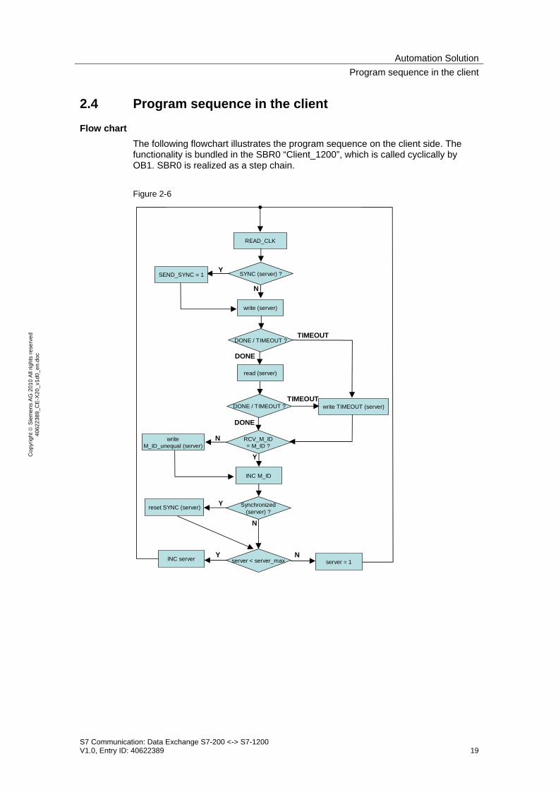
2.4 Program sequence in the client
Flow chart The following flowchart illustrates the program sequence on the client side. The functionality is bundled in the SBR0 “Client_1200”, which is called cyclically by OB1. SBR0 is realized as a step chain. Figure 2-6
SYNC (server) ?
READ_CLK
write (server)
DONE / TIMEOUT ?
read (server)
writeM_ID_unequal (server)
RCV_M_ID= M_ID ?
reset SYNC (server)
write TIMEOUT (server)DONE / TIMEOUT ?
Synchronized(server) ?
INC M_ID
server < server_maxINC server server = 1
Y
N
DONE
TIMEOUT
DONE
TIMEOUT
N
Y
N
Y N
SEND_SYNC = 1
Y

Automation SolutionProgram sequence in the client
S7 Communication: Data Exchange S7-200 <-> S7-1200 V1.0, Entry ID: 40622389 20
Cop
yrig
ht ©
Sie
men
s A
G 2
010
All
right
s re
serv
ed
4062
2389
_CE
-X20
_v1d
0_en
.doc
Description of the flow chart The system time is read cyclically (“READ_CLK”) and written to the send data block. Depending on the server (“server” variable) the synchronization request “SYNC” is read from the synchronization byte “sync_byte”. For a synchronization request it is transferred to the send data (SEND_SYNC = 1). The content of the send data area is transferred to the server (“server”) using the subprogram “ETH0_XFR” (parameter “Data” = 1). Apart from the clock time synchronization information, a message ID “M_ID” is also transferred. If the “server” cannot be reached the maximal processing time “Timeout” elapses and the reception is jumped by the server. For a positive feedback of the send job data is also read from the server (“server”) via the subprogram “ETH0_XFR” (parameter “Data” = 0). The maximal processing time “Timeout” is also checked here. An exceeded “Timeout” time is also stored in the bit for the respective server in the “Timeout_byte”. From the receive data the message ID “M_ID” mirrored by the server is compared with the sent “M_ID”. Any deviation is marked in the bit of the server in the “M_ID_unequal” byte. The message ID is increased (“INC M_ID”). The successful synchronization is read and checked (“synchronized”) from the receive data of the server using the subprogram “Pointer”. In the positive case the synchronization request bit “SYNC” is reset for the respective server in the “sync_byte”. Otherwise, the clock synchronization is repeated at the next communication with this server. The server number “server” is compared with the maximum server number “server_max”. As long as “server_max” has not been reached, the server number is increased (“INC server”). Otherwise, the data exchange with the first server is repeated (“server = 1”).
ConfigurationHardware and software installation
S7 Communication: Data Exchange S7-200 <-> S7-1200 V1.0, Entry ID: 40622389 21
Cop
yrig
ht ©
Sie
men
s A
G 2
010
All
right
s re
serv
ed
4062
2389
_CE
-X20
_v1d
0_en
.doc
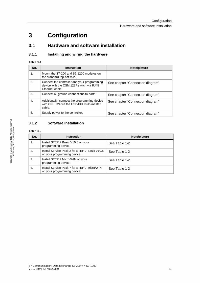
3 Configuration 3.1 Hardware and software installation
3.1.1 Installing and wiring the hardware
Table 3-1
No. Instruction Note/picture
1. Mount the S7-200 and S7-1200 modules on the standard top-hat rails.
2. Connect the controller and your programming device with the CSM 1277 switch via RJ45 Ethernet cable.
See chapter “Connection diagram”
3. Connect all ground connections to earth. See chapter “Connection diagram”
4. Additionally, connect the programming device with CPU 224 via the USB/PPI multi-master cable.
See chapter “Connection diagram”
5. Supply power to the controller. See chapter “Connection diagram”
3.1.2 Software installation
Table 3-2
No. Instruction Note/picture
1. Install STEP 7 Basic V10.5 on your programming device.
See Table 1-2
2. Install Service Pack 2 for STEP 7 Basic V10.5 on your programming device.
See Table 1-2
3. Install STEP 7 Micro/WIN on your programming device.
See Table 1-2
4. Install Service Pack 7 for STEP 7 Micro/WIN on your programming device.
See Table 1-2

ConfigurationHardware and network configuration
S7 Communication: Data Exchange S7-200 <-> S7-1200 V1.0, Entry ID: 40622389 22
Cop
yrig
ht ©
Sie
men
s A
G 2
010
All
right
s re
serv
ed
4062
2389
_CE
-X20
_v1d
0_en
.doc
3.2 Hardware and network configuration
3.2.1 Assigning the IP address of the PG/PC
Your PG/PC must have an IP address assigned to it in the same subnet as the controllers. The IP addresses of the individual nodes are displayed in Figure 1-2. In order to assign the IP address for your network card in the Windows XP operating system please proceed as follows:
Table 3-3
No. Instruction Note/picture
1. Select the “Network Connections” option in the Control Panel.
2. Select the network card to be used and open the properties via right-click.

ConfigurationHardware and network configuration
S7 Communication: Data Exchange S7-200 <-> S7-1200 V1.0, Entry ID: 40622389 23
Cop
yrig
ht ©
Sie
men
s A
G 2
010
All
right
s re
serv
ed
4062
2389
_CE
-X20
_v1d
0_en
.doc
No. Instruction Note/picture
3. Select the element “Internet Protocol (TCP/IP)” and open its properties.
4. • Select “Use the following IP address”
• Enter “192.168.0.241” as an IP address (see Figure 1-2).
• Enter “255.255.255.0” as the subnet mask.
• Click on “OK” to confirm the settings.

ConfigurationHardware and network configuration
S7 Communication: Data Exchange S7-200 <-> S7-1200 V1.0, Entry ID: 40622389 24
Cop
yrig
ht ©
Sie
men
s A
G 2
010
All
right
s re
serv
ed
4062
2389
_CE
-X20
_v1d
0_en
.doc
3.2.2 Configuration of the client
Establishing a connection Configuring the connection, defining the send and receive side occurs unilaterally for the S7-200. STEP 7 Micro/WIN provides the Ethernet wizard for this. Using the Ethernet wizard the Ethernet-CP 243-1 is configured at the same time. The Ethernet wizard has been preconfigured according to the following procedure.
Table 3-4
No. Instruction Note/picture
1. • In STEP 7 MicroWIN you open the Ethernet wizard via the menu “Extras Ethernet wizard…”.
2. In the first step of the Ethernet wizard
you find a description of the Ethernet wizard. • Click the “Next” button to start with
the configuration.
3. • With the selected USB/PPI cable
you can now automatically have the module position of the CP243-1 determined via the “Read Modules” button. However, you can also enter the module position manually.
• Then you click the “Next” button.
ConfigurationHardware and network configuration
S7 Communication: Data Exchange S7-200 <-> S7-1200 V1.0, Entry ID: 40622389 25
Cop
yrig
ht ©
Sie
men
s A
G 2
010
All
right
s re
serv
ed
4062
2389
_CE
-X20
_v1d
0_en
.doc
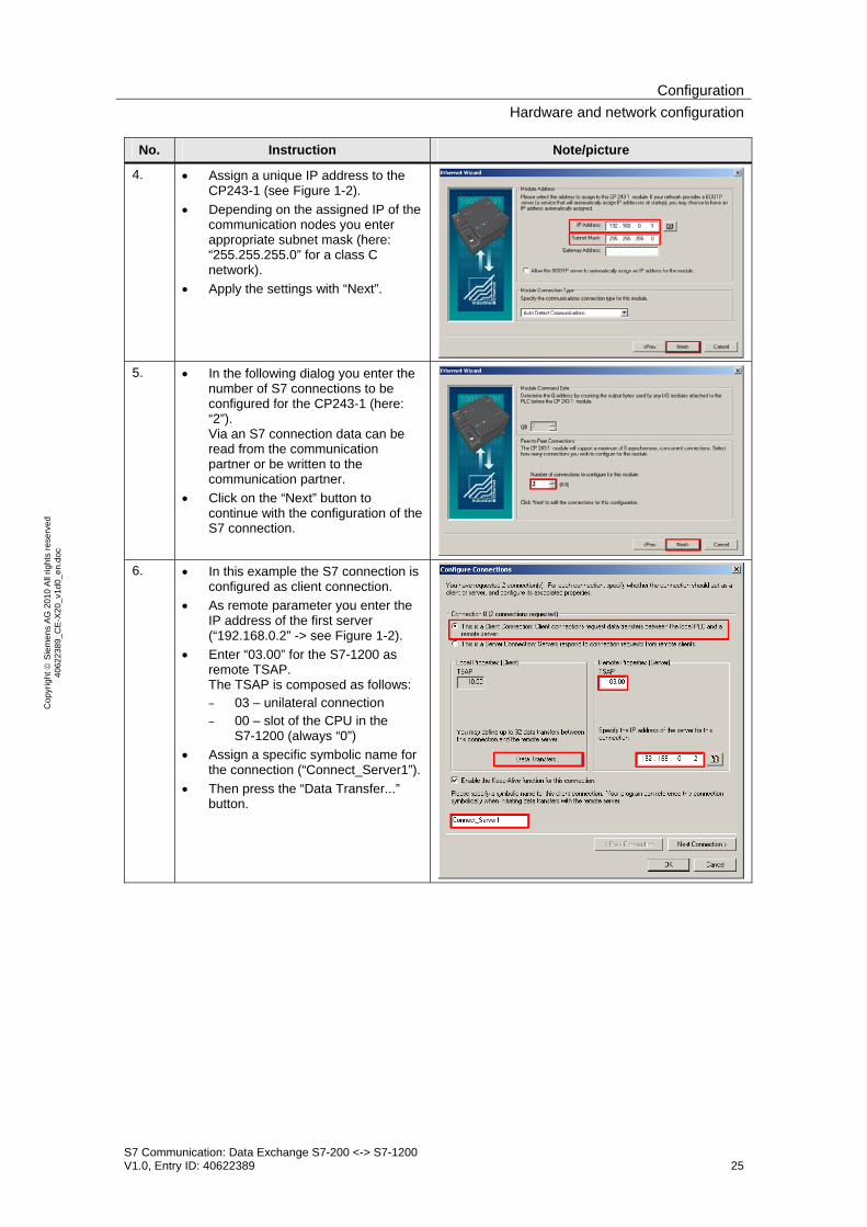
No. Instruction Note/picture
4. • Assign a unique IP address to the CP243-1 (see Figure 1-2).
• Depending on the assigned IP of the communication nodes you enter appropriate subnet mask (here: “255.255.255.0” for a class C network).
• Apply the settings with “Next”.
5. • In the following dialog you enter the
number of S7 connections to be configured for the CP243-1 (here: “2”). Via an S7 connection data can be read from the communication partner or be written to the communication partner.
• Click on the “Next” button to continue with the configuration of the S7 connection.
6. • In this example the S7 connection is
configured as client connection. • As remote parameter you enter the
IP address of the first server (“192.168.0.2” -> see Figure 1-2).
• Enter “03.00” for the S7-1200 as remote TSAP. The TSAP is composed as follows: – 03 – unilateral connection – 00 – slot of the CPU in the
S7-1200 (always “0”) • Assign a specific symbolic name for
the connection (“Connect_Server1”). • Then press the “Data Transfer...”
button.

ConfigurationHardware and network configuration
S7 Communication: Data Exchange S7-200 <-> S7-1200 V1.0, Entry ID: 40622389 26
Cop
yrig
ht ©
Sie
men
s A
G 2
010
All
right
s re
serv
ed
4062
2389
_CE
-X20
_v1d
0_en
.doc
No. Instruction Note/picture
7. • To transfer data to the first server select the function “This data transfer should: Write data to the remote server connection.”
• Specify the volume of data to be written to the server. In this example 100 bytes of data (variables bytes 1000-1099) are send by the S7-200. The data is stored in DB1201 (byte 0-99) of the S7-1200 (see Figure 2-5).
• Assign a symbolic name for the data transmission (“Read_Server1”).
• Assign the “New Transfer...” button to read data from the S7-1200.
8. • To read data from the S7-1200
select the function “This data transfer should: Read data from the remote server connection.”
• Specify the volume of data to be read from the server. In this example 100 bytes of data (byte 0 to 99) are read from the DB1202 of the first server. The data is stored in variable buffer VB1100 to VB1199 of the S7-200 (see Figure 2-5).
• Assign a symbolic name for the data transmission (“Read_Server1”).
• Click “OK” to accept the configured data transfer.
ConfigurationHardware and network configuration
S7 Communication: Data Exchange S7-200 <-> S7-1200 V1.0, Entry ID: 40622389 27
Cop
yrig
ht ©
Sie
men
s A
G 2
010
All
right
s re
serv
ed
4062
2389
_CE
-X20
_v1d
0_en
.doc
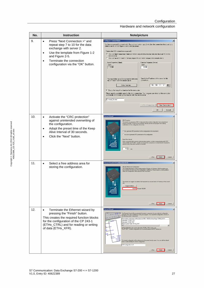
No. Instruction Note/picture
9. • Press “Next Connection >” and repeat step 7 to 10 for the data exchange with server 2.
• Use the template from Figure 1-2 and Figure 2-5.
• Terminate the connection configuration via the “OK” button.
10. • Activate the “CRC protection”
against unintended overwriting of the configuration.
• Adopt the preset time of the Keep Alive Interval of 30 seconds.
• Click the "Next" button.
11. • Select a free address area for
storing the configuration.
12. • Terminate the Ethernet wizard by
pressing the “Finish” button. This creates the required function blocks for the configuration of the CP 243-1 (ETHx_CTRL) and for reading or writing of data (ETHx_XFR).

ConfigurationHardware and network configuration
S7 Communication: Data Exchange S7-200 <-> S7-1200 V1.0, Entry ID: 40622389 28
Cop
yrig
ht ©
Sie
men
s A
G 2
010
All
right
s re
serv
ed
4062
2389
_CE
-X20
_v1d
0_en
.doc
No. Instruction Note/picture
13. • The control block ETH0_CTRL must be called cyclically (in the example in SBR0 “Client_1200” in network 2).
14. • Function block ETH0_XFR is called
for any data direction in SBR0 “Client_1200” (input “Data” = “0” for writing and “Data” = “1” for reading from the communication node.
Load client project to the S7-200 Unzip the example program “CE-X20_Client_v1d0.zip” into any directory on your hard drive.
Table 3-5
No. Instruction Note/picture
1. • In the Windows Explorer you navigate to the S7-200 project “CE-X20_Client_v1d0.mwp” and open it via double-click.

ConfigurationHardware and network configuration
S7 Communication: Data Exchange S7-200 <-> S7-1200 V1.0, Entry ID: 40622389 29
Cop
yrig
ht ©
Sie
men
s A
G 2
010
All
right
s re
serv
ed
4062
2389
_CE
-X20
_v1d
0_en
.doc
No. Instruction Note/picture
2. If the configured IP address as well as the subnet mask of the CP 243-1 are not known, you require an additional communication path to CPU 224 in order to configure the CP 243-1. • Connect your programming device with
CPU 224 via the USB/PPI cable. • In STEP 7 Micro/WIN you open the “Set
PG/PC Interface” view. • Select the used interface configuration
“PC/PPI cable(PPI)” as access path. • Confirm your selection with “OK”.
3. • Load the project into the S7-200 via the “Download to CPU” button.
4. • Select the transfer options: – Program block – Data block – System block
• Press the “Download” button to start the download.
5. • Set your CPU to “STOP” mode for the
download.
6. • Set the CPU back to “Run” mode after the transfer.
ConfigurationHardware and network configuration
S7 Communication: Data Exchange S7-200 <-> S7-1200 V1.0, Entry ID: 40622389 30
Cop
yrig
ht ©
Sie
men
s A
G 2
010
All
right
s re
serv
ed
4062
2389
_CE
-X20
_v1d
0_en
.doc
3.2.3 Configuration of the server
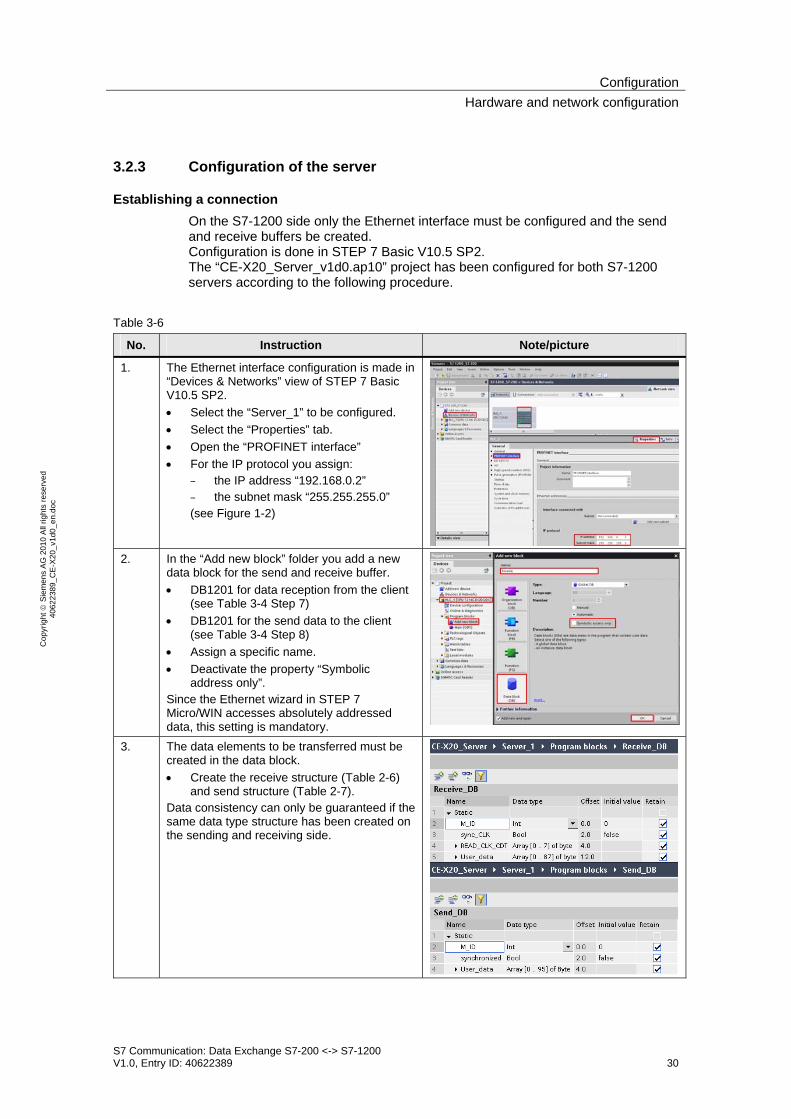
Establishing a connection On the S7-1200 side only the Ethernet interface must be configured and the send and receive buffers be created. Configuration is done in STEP 7 Basic V10.5 SP2. The “CE-X20_Server_v1d0.ap10” project has been configured for both S7-1200 servers according to the following procedure.
Table 3-6
No. Instruction Note/picture
1. The Ethernet interface configuration is made in “Devices & Networks” view of STEP 7 Basic V10.5 SP2. • Select the “Server_1” to be configured. • Select the “Properties” tab. • Open the “PROFINET interface” • For the IP protocol you assign:
– the IP address “192.168.0.2” – the subnet mask “255.255.255.0” (see Figure 1-2)
2. In the “Add new block” folder you add a new
data block for the send and receive buffer. • DB1201 for data reception from the client
(see Table 3-4 Step 7) • DB1201 for the send data to the client
(see Table 3-4 Step 8) • Assign a specific name. • Deactivate the property “Symbolic
address only”. Since the Ethernet wizard in STEP 7 Micro/WIN accesses absolutely addressed data, this setting is mandatory.
3. The data elements to be transferred must be created in the data block. • Create the receive structure (Table 2-6)
and send structure (Table 2-7). Data consistency can only be guaranteed if the same data type structure has been created on the sending and receiving side.

ConfigurationHardware and network configuration
S7 Communication: Data Exchange S7-200 <-> S7-1200 V1.0, Entry ID: 40622389 31
Cop
yrig
ht ©
Sie
men
s A
G 2
010
All
right
s re
serv
ed
4062
2389
_CE
-X20
_v1d
0_en
.doc
Load server project into the S7-1200 controller Unzip the example program “CE-X20_Server_v1d0.zip” into any directory on your hard drive. The unzipped file contains the “CE-X20_Server_v1d0.ap10” project for both S7-1200 controllers.
Table 3-7
No. Instruction Note/picture
1. • In the Windows Explorer you navigate to the S7-1200 project “CE-X20_Server_v1d0.ap10” and open it via double-click.
2. The project is opened in STEP 7 Basic. • Open the Project view.
3. • Select both controller folders “Server_1
[CPU 1212C DC/DC/DC]” and “Server_2 [CPU 1214C DC/DC/DC]”.
• Press the “Extended download to device” button for downloading the entire projects to the controller.
4. • Select the used network card. • Activate the display of all accessible
nodes. • Identify the controller “Server_1” from the
list of accessible nodes via the MAC address or via “Flash LED”.
• Mark the selected controller and press the “Load” button.
Repeat those two points for the download of “Server_2”.

ConfigurationHardware and network configuration
S7 Communication: Data Exchange S7-200 <-> S7-1200 V1.0, Entry ID: 40622389 32
Cop
yrig
ht ©
Sie
men
s A
G 2
010
All
right
s re
serv
ed
4062
2389
_CE
-X20
_v1d
0_en
.doc
No. Instruction Note/picture
5. • Activate the consistent loading for both controllers.
• Press the “Load” button.
6. After transferring all program blocks to the controller a window appears with the “Download result”. • Select the “Start all” fields to set both
controllers to “Run” mode. • Terminate the download via the “Finish”
button.

ConfigurationActivate the online mode
S7 Communication: Data Exchange S7-200 <-> S7-1200 V1.0, Entry ID: 40622389 33
Cop
yrig
ht ©
Sie
men
s A
G 2
010
All
right
s re
serv
ed
4062
2389
_CE
-X20
_v1d
0_en
.doc
3.3 Activate the online mode
For control and monitoring of the communication your PG/PC must be switched online to S7-200 and S7-1200 via the status table / watch table.
Activate table status for the S7-200 client
Table 3-8
No. Instruction Note/picture
1. In the STEP 7 Micro/WIN project “CE-X20_Client_v1d0.mwp” you press the “Table status” button.
2. The status table “USER1” opens. It contains (row numbers in brackets): • Monitoring information (2-17)
– Default synchronization time (2-3) – Maximum processing time (4) – Step detail (5) – Currently addressed server (6)
• Status information per server (8-13) – Synchronization request (8-10) – Exceeding of processing time (11) – Unequal message ID (12) – Channel check (13)
• Communication error (15-18) – Error status of the control block (15) – Error status during writing (16) – Error status during reading (17) – Ready message of the CP (18)
• Send data (20-30) – Message ID (20) – Synchronization request (21) – Client system time in
DATE_AND_TIME format (22-29) – First byte of the user data (30)
• Receive data of server 1 (32-34) – Message ID (32) – Synchronization
acknowledgement (33) – First byte of the user data (34)
• Receive data of server 2 (36-38)
ConfigurationActivate the online mode
S7 Communication: Data Exchange S7-200 <-> S7-1200 V1.0, Entry ID: 40622389 34
Cop
yrig
ht ©
Sie
men
s A
G 2
010
All
right
s re
serv
ed
4062
2389
_CE
-X20
_v1d
0_en
.doc
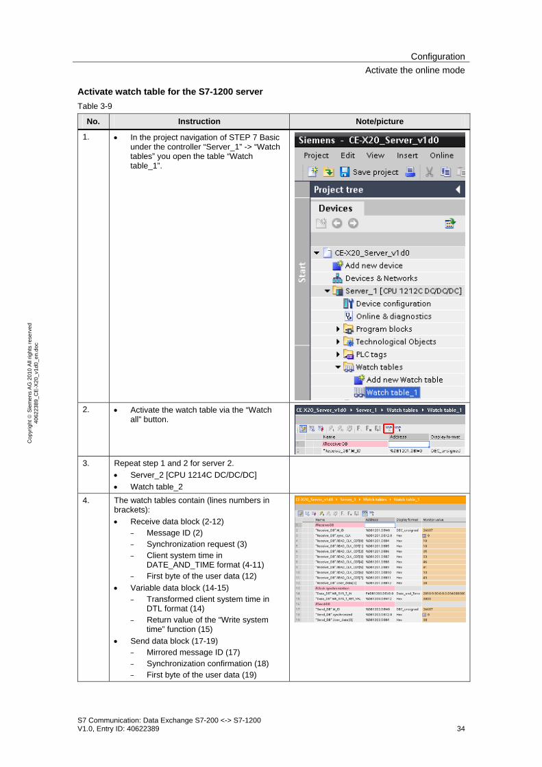
Activate watch table for the S7-1200 server Table 3-9
No. Instruction Note/picture
1. • In the project navigation of STEP 7 Basic under the controller “Server_1” -> “Watch tables” you open the table “Watch table_1”.
2. • Activate the watch table via the “Watch all” button.
3. Repeat step 1 and 2 for server 2.
• Server_2 [CPU 1214C DC/DC/DC] • Watch table_2
4. The watch tables contain (lines numbers in brackets): • Receive data block (2-12)
– Message ID (2) – Synchronization request (3) – Client system time in
DATE_AND_TIME format (4-11) – First byte of the user data (12)
• Variable data block (14-15) – Transformed client system time in
DTL format (14) – Return value of the “Write system
time” function (15) • Send data block (17-19)
– Mirrored message ID (17) – Synchronization confirmation (18) – First byte of the user data (19)

ConfigurationLive Demo
S7 Communication: Data Exchange S7-200 <-> S7-1200 V1.0, Entry ID: 40622389 35
Cop
yrig
ht ©
Sie
men
s A
G 2
010
All
right
s re
serv
ed
4062
2389
_CE
-X20
_v1d
0_en
.doc
3.4 Live Demo
3.4.1 Cyclical sequence
Table 3-10
No. Instruction Note/picture
1. • The subprogram SBR0 “Client_1200” of S7-200 is called cyclically (apparent by the changed step display in line 5)
• It communicates continuously with server 1 and 2 (apparent by the change in server number in row 6).
• Reaching both servers is signaled by bit 0 and 1 of VB12 in row 13.
• Writing to the server alternates with reading from the server which is why the inactive direction gives the status “16#82” (row 16/17).
• The odd message IDs are sent to server 1, where they are mirrored and received again.
• The even message IDs are sent to server 2, where they are mirrored and received again.
3.4.2 User data transfer
Client -> Server
Table 3-11
No. Instruction Note/picture
1. As an example for the user data transmission from the client to the servers the send byte 0 of the user data in row 30 shall be modified: • Enter a value in row 30 of the “New Value”
column. • Accept the value with the “Write all”
button. 2. The value is transferred to both slaves and
written to the receive byte 0 of the user data field in the receive data block 1201 (apparent in rows 12 of the server watch table).

ConfigurationLive Demo
S7 Communication: Data Exchange S7-200 <-> S7-1200 V1.0, Entry ID: 40622389 36
Cop
yrig
ht ©
Sie
men
s A
G 2
010
All
right
s re
serv
ed
4062
2389
_CE
-X20
_v1d
0_en
.doc
Server 1 -> Client
Table 3-12
No. Instruction Note/picture
1. As an example for the user data transmission from server 1 to the client, the send byte 0 of the user data field in row 19 shall be modified: • In the monitoring table “Watch table_1”
you enter a value in row 19 of the “Modify value” column.
• Accept the value by right-clicking “Modify” -> “Modify now”.
2. The value is transferred to the client and written to the first user data byte of the receive area for server 1 (apparent in row 34 of the client status table).
Server 2 -> Client
Table 3-13
No. Instruction Note/picture 1. As an example for the user data transmission
from server 2 to the client, the send byte 0 of the user data field in row 19 shall be modified: • In the monitoring table “Watch table_2”
you enter a value in row 19 of the “Modify value” column.
• Accept the value by right-clicking “Modify” -> “Modify now”.
2. The value is transferred to the client and written to the first user data byte of the receive area for server 2 (apparent in row 38 of the client status table).
ConfigurationLive Demo
S7 Communication: Data Exchange S7-200 <-> S7-1200 V1.0, Entry ID: 40622389 37
Cop
yrig
ht ©
Sie
men
s A
G 2
010
All
right
s re
serv
ed
4062
2389
_CE
-X20
_v1d
0_en
.doc
3.4.3 Time synchronization
The synchronization time written to the system time of the S7-1200 server is the UTC time. The real-time clock of the S7-200 client must be set to UTC time. The time is set in STEP 7 Micro/WIN under menu item “PLC” -> “Time of Day Clock…”.
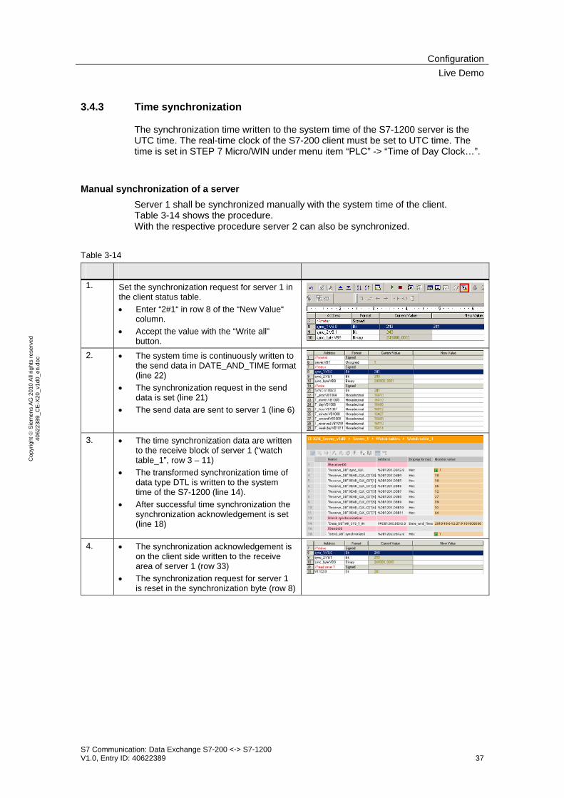
Manual synchronization of a server Server 1 shall be synchronized manually with the system time of the client. Table 3-14 shows the procedure. With the respective procedure server 2 can also be synchronized.
Table 3-14
1. Set the synchronization request for server 1 in
the client status table. • Enter “2#1“ in row 8 of the “New Value“
column. • Accept the value with the “Write all”
button.
2. • The system time is continuously written to the send data in DATE_AND_TIME format (line 22)
• The synchronization request in the send data is set (line 21)
• The send data are sent to server 1 (line 6)
3. • The time synchronization data are written
to the receive block of server 1 (“watch table_1”, row 3 – 11)
• The transformed synchronization time of data type DTL is written to the system time of the S7-1200 (line 14).
• After successful time synchronization the synchronization acknowledgement is set (line 18)
4. • The synchronization acknowledgement is
on the client side written to the receive area of server 1 (row 33)
• The synchronization request for server 1 is reset in the synchronization byte (row 8)

ConfigurationLive Demo
S7 Communication: Data Exchange S7-200 <-> S7-1200 V1.0, Entry ID: 40622389 38
Cop
yrig
ht ©
Sie
men
s A
G 2
010
All
right
s re
serv
ed
4062
2389
_CE
-X20
_v1d
0_en
.doc
Automatic synchronization of all servers The daily synchronization time of all slaves can be set via the initial default value in the data block of the S7-200 project “CE-X20_Client_v1d0.mwp” or via the status table. The respective parameters “hour” and “minute” are kept remnant.
Table 3-15
No. Instruction Note/picture
1. The current system time of the S7-200 client can be read via row 25 and 26 (here: 13:22). • Set the daily synchronization time to one
minute in the future via row 2 and 3 (here: 13:22) and accept the settings with the “Write all” button.
2. The successful time synchronization of the servers can be checked via the written system time of the server (line 14 in the watch tables “Watch table_1” and “Watch table_2”).

ConfigurationLive Demo
S7 Communication: Data Exchange S7-200 <-> S7-1200 V1.0, Entry ID: 40622389 39
Cop
yrig
ht ©
Sie
men
s A
G 2
010
All
right
s re
serv
ed
4062
2389
_CE
-X20
_v1d
0_en
.doc
3.4.4 Communication errors
Pulling the Ethernet cable from server 1 the communication error evaluation shall be demonstrated. Table 3-16 shows the procedure. With the respective procedure a communication interruption with server 2 can be simulated and evaluated.
Table 3-16
No. Instruction Note/picture
1. Pull the Ethernet cable from the LAN connection of server 1.
2. • The interruption with server 1 is initially not recognized (row 13: Bit12.0 = “1”).
• However, exceeding the maximum processing time of 500ms (row 4) is displayed in row 11 (Bit10.0 = “1”).
• Additionally, bit 11.0 in row 12 indicates that the sent message ID (row 20) is not identical with the one last received by server 1 (row 32).
3. • After approx. 40 seconds the interrupted
connection with server 1 is recognized and represented in row 13 (Bit12.0 = “0”) .
• Data exchange with server 1 is jumped. There is no check of the maximum processing time (row 11: V10.0 = “0”).
• The deviation between the sent message ID (row 20) and the one last received by server 1 (row 32) is detected and output in row 12 (Bit11.0 = “1”).
4. Reconnect the Ethernet cable with the LAN
connection of server 1.
5. • After detecting the recurring connection of server 1 (row 13: Bit12.0 = “1”), data exchange occurs with server 1 and checking the message ID is positive (row 12 Bit11.0 = “0”).
3.4.5 Voltage failure of the client
After recurring voltage of the S7-200 client the step chain of subprogram SBR0 “Client_1200” continues from the last performed position.

Code Elements
S7 Communication: Data Exchange S7-200 <-> S7-1200 V1.0, Entry ID: 40622389 40
Cop
yrig
ht ©
Sie
men
s A
G 2
010
All
right
s re
serv
ed
4062
2389
_CE
-X20
_v1d
0_en
.doc
4 Code Elements In the example on hand the following program codes are used. Table 4-1
No. File name Content
1. CE-X20_Client_v1d0.zip • CE-X20_Client_v1d0.mwp
Zip-file with the S7-1200 client project for the deterministic S7 communication with S7-1200 servers
2. CE-X20_Server_v1d0.zip • CE-X20_Server_v1d0.ap10
Zip-file with the S7-1200 server project for the deterministic S7 communication with S7-200 client
History
S7 Communication: Data Exchange S7-200 <-> S7-1200 V1.0, Entry ID: 40622389 41
Cop
yrig
ht ©
Sie
men
s A
G 2
010
All
right
s re
serv
ed
4062
2389
_CE
-X20
_v1d
0_en
.doc
5 History Table 5-1
Version Date Changes
V1.0 07.10.2010 First publication