Embed Size (px)
Citation preview

Visit our Website for more information on this product
www.diversitech.ca
1200 55th Avenue, Montreal, Quebec H8T 3J8Tel: 1.800.361.3733 | Fax: 1.514.631.9480 | [email protected]
READ AND SAVE THESE INSTRUCTIONS
DD-4X4, DD-4X6 DD-4X8, DD-5X10
Multi Workstation Tables
DD-3X4, DD-3X6, DD-3X8Single Workstation Tables
Operation & Maintenance Manual
INDUSTRIAL DOWNDRAFT TABLES
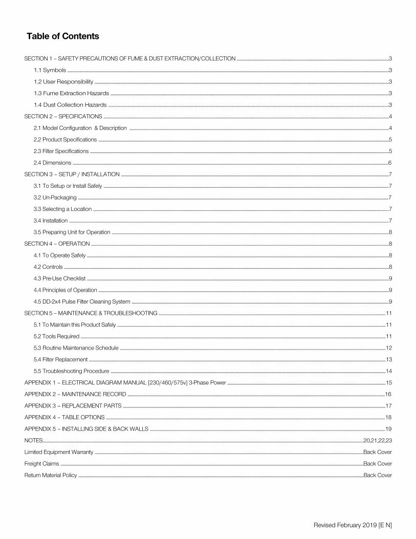
Table of Contents
SECTION 1 – SAFETY PRECAUTIONS OF FUME & DUST EXTRACTION/COLLECTION ..................................................................................................................................................3
1.1 Symbols ...........................................................................................................................................................................................................................................................................................3
1.2 User Responsibility ...................................................................................................................................................................................................................................................................3
1.3 Fume Extraction Hazards .....................................................................................................................................................................................................................................................3
1.4 Dust Collection Hazards .......................................................................................................................................................................................................................................................3
SECTION 2 – SPECIFICATIONS ..................................................................................................................................................................................................................................................................................4
2.1 Model Configuration & Description .........................................................................................................................................................................................................................................................4
2.2 Product Specifications .......................................................................................................................................................................................................................................................................................5
2.3 Filter Specifications ...............................................................................................................................................................................................................................................................................................5
2.4 Dimensions ...............................................................................................................................................................................................................................................................................................................6
SECTION 3 – SETUP / INSTALLATION .................................................................................................................................................................................................................................................................7
3.1 To Setup or Install Safely ..................................................................................................................................................................................................................................................................................7
3.2 Un-Packaging ..........................................................................................................................................................................................................................................................................................................7
3.3 Selecting a Location ............................................................................................................................................................................................................................................................................................7
3.4 Installation ...................................................................................................................................................................................................................................................................................................................7
3.5 Preparing Unit for Operation ..........................................................................................................................................................................................................................................................................8
SECTION 4 – OPERATION ..............................................................................................................................................................................................................................................................................................8
4.1 To Operate Safely ..................................................................................................................................................................................................................................................................................................8
4.2 Controls ........................................................................................................................................................................................................................................................................................................................8
4.3 Pre-Use Checklist ..................................................................................................................................................................................................................................................................................................9
4.4 Principles of Operation .......................................................................................................................................................................................................................................................................................9
4.5 DD-2x4 Pulse Filter Cleaning System .......................................................................................................................................................................................................................................................9
SECTION 5 – MAINTENANCE & TROUBLESHOOTING ..........................................................................................................................................................................................................................11
5.1 To Maintain this Product Safely ..................................................................................................................................................................................................................................................................11
5.2 Tools Required .....................................................................................................................................................................................................................................................................................................11
5.3 Routine Maintenance Schedule ...............................................................................................................................................................................................................................................................12
5.4 Filter Replacement .............................................................................................................................................................................................................................................................................................13
5.5 Troubleshooting Procedure ........................................................................................................................................................................................................................................................................14
APPENDIX 1 – ELECTRICAL DIAGRAM MANUAL [230/460/575v] 3-Phase Power ........................................................................................................................................................15
APPENDIX 2 – MAINTENANCE RECORD .......................................................................................................................................................................................................................................................16
APPENDIX 3 – REPLACEMENT PARTS ............................................................................................................................................................................................................................................................17
APPENDIX 4 – TABLE OPTIONS ............................................................................................................................................................................................................................................................................18
APPENDIX 5 – INSTALLING SIDE & BACK WALLS ..................................................................................................................................................................................................................................19
NOTES....................................................................................................................................................................................................................................................................................................................20,21,22,23
Limited Equipment Warranty ..................................................................................................................................................................................................................................................................Back Cover
Freight Claims ...................................................................................................................................................................................................................................................................................................Back Cover
Return Material Policy ..................................................................................................................................................................................................................................................................................Back Cover
Revised February 2019 [E N]

!!!
!
!
3
• Dusts from many welding, cutting, grinding, painting, or deburring applications can be combustible. • Do not use or install equipment where any potential for combustible fumes or dusts are present, until a qualified person has indicated it is safe to do so.• Never use or install equipment where the potential for combustible fumes or dusts are present without a fire/explosion protection system.• If you are unsure if the product you purchased is correct for your application, call Diversitech at 1-800-361-3733.
1.4 Dust Collection Hazards
• Breathing smoke, fumes, or dusts produced in applications such as welding, cutting, grinding, painting, deburring are hazardous to user’s health. Proper ventilation or use of well maintained fume extraction and/or dust collection equipment helps the user avoid these hazards. • Breathable contaminants may not be visible or have an odor. • Stop operation and leave the area immediately if 1) breathing becomes difficult, 2) experience dizziness, impaired vision, 4) or eye/nose/mouth irritation.
1.3 Fume Extraction Hazards
• Improper use can be hazardous.• It is your responsibility to follow all applicable ANSI, OSHA, UL, CSA, National & Local Fire Codes, and other regulatory guidelines covering the safe use of equipment that extracts fumes, collects dusts, and exhausts filtered air either indoors or outdoors. • Before use, inspect the unit for damage and verify it is working properly. • Only qualified persons should install, operate, maintain, or repair this unit.• Do not modify or repair the unit with parts or accessories not supplied by the manufacturer.• Consult filter manufacturer’s instructions for filter use and reuse, including instructions for cleaning.
1.2 Users Responsability
1.1 Symbols
HOT
PARTS
MOVING
PARTS
ELECTRIC
SHOCK
WARNING!
DANGER!
DO
NOT
USE
READ
BEFORE
USE
SECTION 1 - SAFETY PRECAUTIONS OF FUME & DUST EXTRACTION/COLLECTION
This manual contains specific cautionary statements related to worker safety. To protect yourself and others, read this manual thoroughly and follow as directed before use. Not all hazards of fume & dust control are listed in this manual, and no hazards related to welding, cutting, grinding, painting, deburring or other applications are listed. Consult a qualified safety professional.
This manual uses several symbols to highlight specific hazards. Be familiar with these symbols and when you see them in this manual, read adjoining warning text to avoid the hazard.
Do not use this equipment:• To extract combustible dusts, liquid vapors, aggressive fumes such as acids.• To extract smoke or fumes above 180°F / 82°C.• If the power cord has been damaged or ground (third prong) removed.• Without a filter.

Model Open Works surface Side/Back Walls Clean Air Workstation
DD-3X4
DD-3X6
DD-3X8
DD-4X4
DD-4X6
DD-4X8
DD-5X10
4
SECTION 2 - SPECIFICATIONS
2.1 Model Configurations & Description
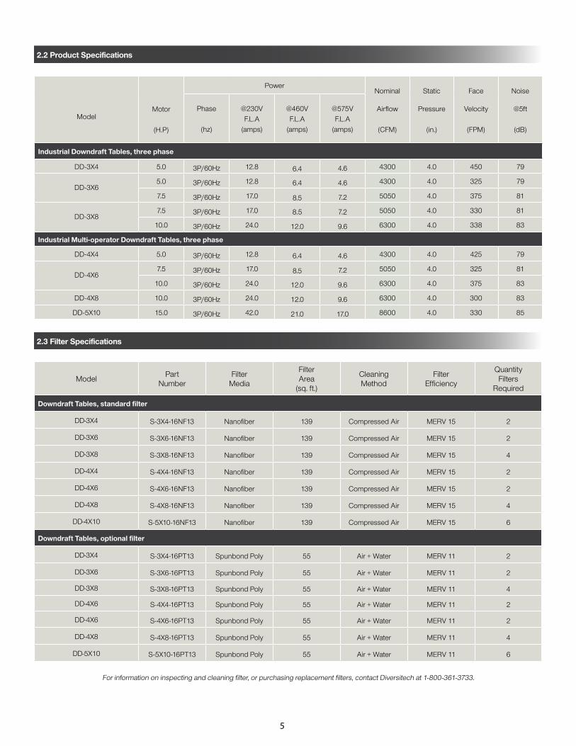
2.2 Product Specifications
ModelMotor
(H.P)
PowerNominal
Airflow
(CFM)
Static
Pressure
(in.)
Face
Velocity
(FPM)
Noise
@5ft
(dB)
Phase
(hz)
@230VF.L.A
(amps)
@460VF.L.A
(amps)
@575VF.L.A
(amps)
Industrial Downdraft Tables, three phase
DD-3X4 5.0 3P/60Hz 12.8 6.4 4.6 4300 4.0 450 79
DD-3X65.0 3P/60Hz 12.8 6.4 4.6 4300 4.0 325 79
7.5 3P/60Hz 17.0 8.5 7.2 5050 4.0 375 81
DD-3X87.5 3P/60Hz 17.0 8.5 7.2 5050 4.0 330 81
10.0 3P/60Hz 24.0 12.0 9.6 6300 4.0 338 83
Industrial Multi-operator Downdraft Tables, three phase
DD-4X4 5.0 3P/60Hz 12.8 6.4 4.6 4300 4.0 425 79
DD-4X67.5 3P/60Hz 17.0 8.5 7.2 5050 4.0 325 81
10.0 3P/60Hz 24.0 12.0 9.6 6300 4.0 375 83
DD-4X8 10.0 3P/60Hz 24.0 12.0 9.6 6300 4.0 300 83
DD-5X10 15.0 3P/60Hz 42.0 21.0 17.0 8600 4.0 330 85
ModelPart
NumberFilter
Media
FilterArea
(sq. ft.)
CleaningMethod
FilterEfficiency
QuantityFilters
Required
Downdraft Tables, standard filter
DD-3X4 S-3X4-16NF13 Nanofiber 139 Compressed Air MERV 15 2
DD-3X6 S-3X6-16NF13 Nanofiber 139 Compressed Air MERV 15 2
DD-3X8 S-3X8-16NF13 Nanofiber 139 Compressed Air MERV 15 4
DD-4X4 S-4X4-16NF13 Nanofiber 139 Compressed Air MERV 15 2
DD-4X6 S-4X6-16NF13 Nanofiber 139 Compressed Air MERV 15 2
DD-4X8 S-4X8-16NF13 Nanofiber 139 Compressed Air MERV 15 4
DD-4X10 S-5X10-16NF13 Nanofiber 139 Compressed Air MERV 15 6
Downdraft Tables, optional filter
DD-3X4 S-3X4-16PT13 Spunbond Poly 55 Air + Water MERV 11 2
DD-3X6 S-3X6-16PT13 Spunbond Poly 55 Air + Water MERV 11 2
DD-3X8 S-3X8-16PT13 Spunbond Poly 55 Air + Water MERV 11 4
DD-4X6 S-4X4-16PT13 Spunbond Poly 55 Air + Water MERV 11 2
DD-4X6 S-4X6-16PT13 Spunbond Poly 55 Air + Water MERV 11 2
DD-4X8 S-4X8-16PT13 Spunbond Poly 55 Air + Water MERV 11 4
DD-5X10 S-5X10-16PT13 Spunbond Poly 55 Air + Water MERV 11 6
For information on inspecting and cleaning filter, or purchasing replacement filters, contact Diversitech at 1-800-361-3733.
2.3 Filter Specifications
5

Model
Exhaust
Diameter
(in.)
Footprint
(in.)
Work surface
(in.)
Table
Height
[f/S&B/CAW]
Net
Weight
(lbs.)
Exhaust
[g]
Overhang
[h]
(in.)
Length[b]
Width[a]
Height[C]
Length[e]
Width[d]
Downdraft Tables, Standard Size
DD-3X4 10 x 2 43 62 68.5 42 48 36/69/84 258 14 6
DD-3X6 10 x 2 43 87 68.5 42 72 36/69/84 329 14 6
DD-3X8 10 x 2 43 111 68.5 42 96 36/69/84 421 14 6
DD-4X4 10 x 2 49 63 68.5 48 48 36/69/84 621 14 6 x 2
DD-4X6 10 x 2 49 87 68.5 48 72 36/69/84 729 14 6 x 2
DD-4X8 10 x 2 49 111 68.5 48 96 36/69/84 875 14 6 x 2
DD-5X10 10 x 2 61 155 68.5 60 120 36/69/84 1107 34 12 x 2
Downdraft Tables, extended overhang
DD-3X4-EO 10 x 2 49 63 68.5 48 48 36/69/84 258 14 12
DD-3X6-EO 10 x 2 49 87 68.5 48 72 36/69/84 329 14 12
DD-3X8-EO 10 x 2 49 111 68.5 48 96 36/69/84 421 14 12
DD-4X4-EO 10 x 2 61 63 68.5 60 48 36/69/84 621 14 12 x 2
DD-4X6-EO 10 x 2 61 87 68.5 60 72 36/69/84 729 14 12 x 2
6
2.4 Dimensions

!
7
3.1 To Setup or Install Safely
• Do not place unit near flammables or combustible surface.• Refer to SECTION 2: Specifications, to know the electrical requirements of the unit you are installing and ensure adequate input power that is properly sized, rated, and protected.• This unit must be grounded for safe operation.
3.2 Un-Packaging
3.3 Selecting a Location
• Choose a location where the unit will be used, near the operator.• Choose a location sufficiently close to a grounded power source.
3.4 Installation
SECTION 3 - SETUP / INSTALLATION
1. Immediately upon receiving the unit, carefully examine the carton for damage during transit. 2. Remove packing material.3. Avoid tipping or inverting during handling.4. The item serial number, model, and electrical ratings are listed on the nameplate. Record this information in the Maintenance Record provided in APPENDIX 2: Maintenance Record, or your own preventative maintenance system.
• Electrical Connection for units requiring: 3-phase (230/460/575V) direct connection.: - See APPENDIX 1: Electrical Diagram for wiring instructions. - Have a certified electrician install electrical connection according to local regulations. - All three power leads must be connected to L1, L2 and L3 on the contactor. - This unit must be grounded for safe operation. - If on start-up the downdraft table seems to be lacking performance or the table sounds very loud, the motor is most likely running in the reverse direction. Reversing leads L1 and L3 will reverse motor rotation in the right direction. - Correct direction of BLOWER WHEEL ROTATION = CLOCKWISE.
• For units requiring Compressed Air: - Supply 80-90 PSI of CLEAN, DRY, compressed air to the bulkhead bushing on the side of the unit. - The air tank in the downdraft table is fabricated to allow a maximum of 90 PSI, DO NOT attempt to supply air pressure greater than 90 PSI without a properly installed pressure regulator. - Moisture in airline can damage filter(s); use an air dryer if required.• Special Installation steps for table options: - Side & Back Walls Installation – See APPENDIX 4A: Installing Side & Back Walls - Plasma Cutting Packages & Kits - Spray Painting Packages & Kits

!
8
4.2 Controls
• Read and understand SECTION 1: Safety Precautions and SECTION 4: Operation before use• Read and understand all Material Safety Data Sheets and Manufacturer’s instructions of all process materials, consumables, and equipment used in conjunction with this equipment.• Keep away from all mechanical moving parts including motor, gears, and other pinch points.• Do not use product without first confirming if a Spark Arrestor is required and installed for the type of dust, or fumes you are extracting and/or collection. If you are unsure, call a Diversitech representative at 1-800-361-3733.
3.5 Preparing Unit for Operation
• Remove all packaging and shipping protection before use, in accordance with SECTION 3.2: Un-Packaging• Select a location appropriate for use that complies with all safety instructions contained herein, and SECTION 3.3: Selecting a Location• Confirm installation of correct input power source, compressed air, and any special installation requirements, in accordance with SECTION 3.3: Installation. Look at the manufacturer’s label located on the exterior of the unit and ensure the source is correctly sized in terms of Voltage and Amperes. • Prior to use in your application, turn the unit ON, and perform a function test. To do so: - Turn switch to ON position - LOOK: Is the unit level, stable, and that nothing is obstructing the extraction path? - LISTEN: Does the motor and suction sound smooth and within expected volumes? - FEEL: Place your hand on top of the unit and sense for unexpected vibration. Place your hand in front of the intake surface and sense for expected level(s) of suction.• Inform all potential users of this equipment where they may find and review this manual.
4.1 Operate Safely
SECTION 4 - OPERATION

9
4.5 Reverse Pulse Filter Cleaning System
4.4 Principles of Operation
• Prior to use in your application, turn the unit ON, and perform a function test. To do so: - Turn switch to ON position - LOOK: Is the unit level, stable, and that nothing is obstructing the extraction path? - LISTEN: Does the motor and suction sound smooth and within expected volumes? - FEEL: Place your hand on top of the unit and sense for unexpected vibration. Place your hand in front of the intake surface and sense for expected level(s) of suction.• Inform all potential users of this equipment where they may find and review this manual.
This product is designed to capture and clean smoke and dust from medium & heavy duty welding, soldering, and grinding applications. When operating, air is drawn in through the table surface grating, passes through spark-arrestor baffling, then through the table’s filtration system, and exhausted through the side exhaust.
This product consists of seven basic components:
1. Protective table surface grating(s)
2. Multi-stage spark-Arrestance baffling
3. Table cabinet
4. Cartridge Filter(s)
5. Motor/Blower Assembly
6. Reverse pulse filter cleaning system
7. Dust Drawer
4.3 Pre-Use Checklist
The downdraft table is equipped with a reverse pulse automatic filter cleaning system. This system is controlled by a PC board inside the control box (Labelled “AVP-Z”). Changing the dip switch settings on the AVP-Z board, allows you to control:
1. Pulsing online or offline
2. Number of pulses
3. Pulse duration
Solenoid operated air valves discharge large blasts of air through the filter cartridges thus dislodging particles embedded in the filter media. The particles fall into a dust drawer located below the cartridge. The angled v-shaped baffles above the drawer prevent the dust from re-entering the cabinet when the machine is turned on.
Neglecting to pulse the filter regularly will reduce filter life.
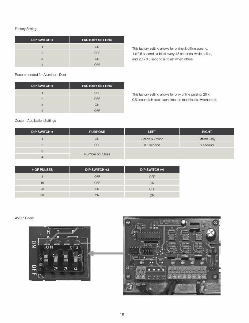
DIP SWITCH # FACTORY SETTING
1 ON
2 OFF
3 ON
4 OFF
DIP SWITCH # FACTORY SETTING
1 OFF
2 OFF
3 ON
4 OFF
# OF PULSES DIP SWITCH #3 DIP SWITCH #4
5 OFF OFF
10 OFF ON
20 ON OFF
30 ON ON
DIP SWITCH # PURPOSE LEFT RIGHT
1 ON Online & Offline Offline Only
2 OFF 0.5 second 1 second
3Number of Pulses
4
10
Factory Setting
Recommended for Aluminum Dust
Custom Application Settings
AVP-Z Board
This factory setting allows for online & offline pulsing.
1 x 0.5 second air blast every 45 seconds, while online,
and 20 x 0.5 second air blast when offline.
This factory setting allows for only offline pulsing, 20 x
0.5 second air blast each time the machine is switched off.
!
!
!
11
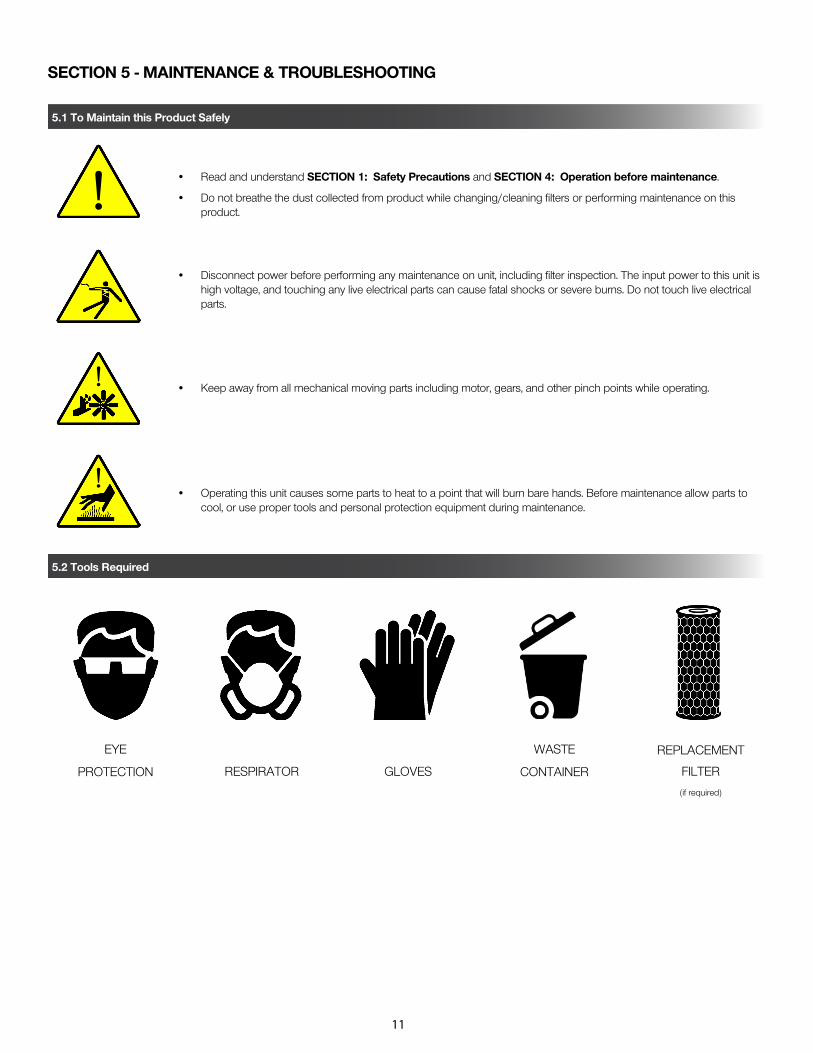
SECTION 5 - MAINTENANCE & TROUBLESHOOTING
5.1 To Maintain this Product Safely
5.2 Tools Required
EYE
PROTECTION RESPIRATOR GLOVES
WASTE
CONTAINER
REPLACEMENT
FILTER
(if required)
• Read and understand SECTION 1: Safety Precautions and SECTION 4: Operation before maintenance.
• Do not breathe the dust collected from product while changing/cleaning filters or performing maintenance on this product.
• Disconnect power before performing any maintenance on unit, including filter inspection. The input power to this unit is high voltage, and touching any live electrical parts can cause fatal shocks or severe burns. Do not touch live electrical parts.
• Keep away from all mechanical moving parts including motor, gears, and other pinch points while operating.
• Operating this unit causes some parts to heat to a point that will burn bare hands. Before maintenance allow parts to cool, or use proper tools and personal protection equipment during maintenance.
!
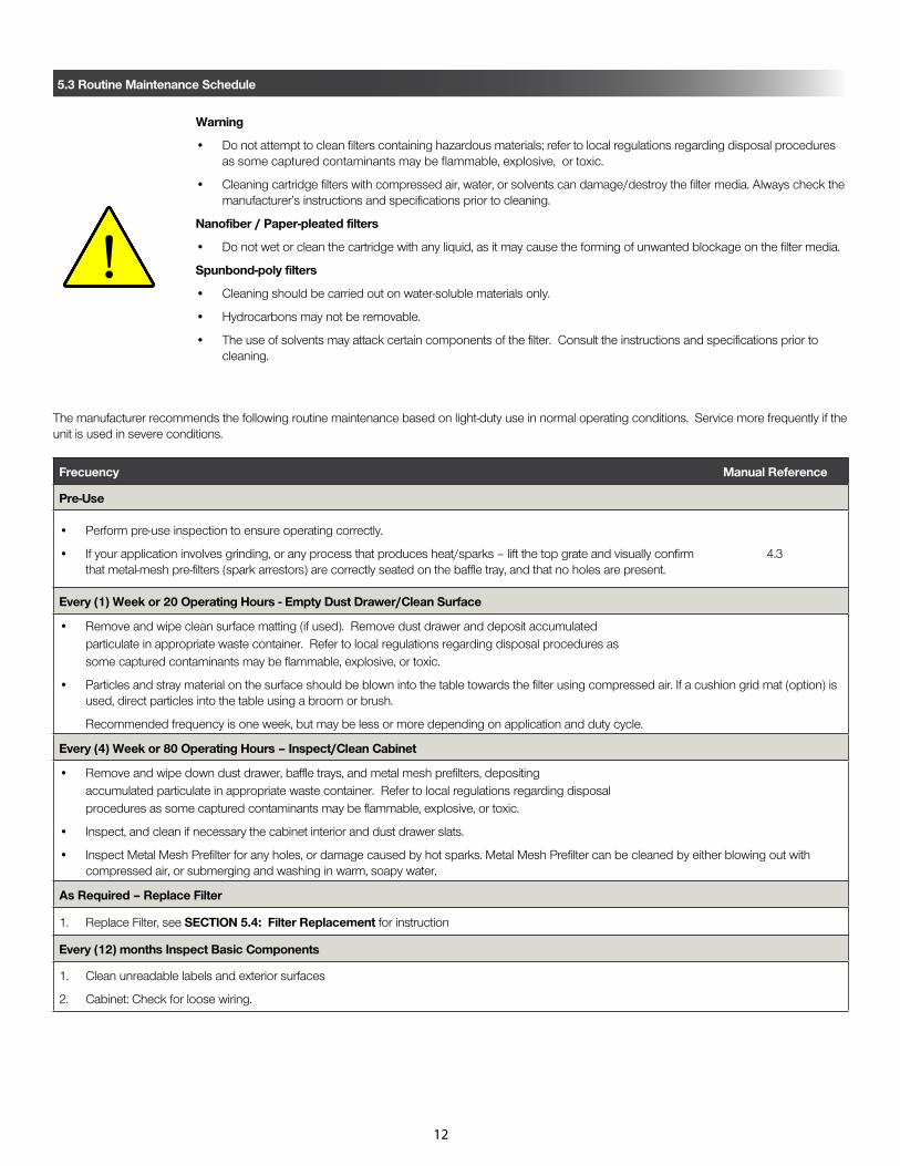
Frecuency Manual Reference
Pre-Use
• Perform pre-use inspection to ensure operating correctly.
• If your application involves grinding, or any process that produces heat/sparks – lift the top grate and visually confirm 4.3 that metal-mesh pre-filters (spark arrestors) are correctly seated on the baffle tray, and that no holes are present.
Every (1) Week or 20 Operating Hours - Empty Dust Drawer/Clean Surface
• Remove and wipe clean surface matting (if used). Remove dust drawer and deposit accumulated particulate in appropriate waste container. Refer to local regulations regarding disposal procedures as some captured contaminants may be flammable, explosive, or toxic.
• Particles and stray material on the surface should be blown into the table towards the filter using compressed air. If a cushion grid mat (option) is used, direct particles into the table using a broom or brush.
Recommended frequency is one week, but may be less or more depending on application and duty cycle.
Every (4) Week or 80 Operating Hours – Inspect/Clean Cabinet
• Remove and wipe down dust drawer, baffle trays, and metal mesh prefilters, depositing accumulated particulate in appropriate waste container. Refer to local regulations regarding disposal procedures as some captured contaminants may be flammable, explosive, or toxic.
• Inspect, and clean if necessary the cabinet interior and dust drawer slats.
• Inspect Metal Mesh Prefilter for any holes, or damage caused by hot sparks. Metal Mesh Prefilter can be cleaned by either blowing out with compressed air, or submerging and washing in warm, soapy water.
As Required – Replace Filter
1. Replace Filter, see SECTION 5.4: Filter Replacement for instruction
Every (12) months Inspect Basic Components
1. Clean unreadable labels and exterior surfaces
2. Cabinet: Check for loose wiring.
12
Warning
• Do not attempt to clean filters containing hazardous materials; refer to local regulations regarding disposal procedures as some captured contaminants may be flammable, explosive, or toxic.
• Cleaning cartridge filters with compressed air, water, or solvents can damage/destroy the filter media. Always check the manufacturer’s instructions and specifications prior to cleaning.
Nanofiber / Paper-pleated filters
• Do not wet or clean the cartridge with any liquid, as it may cause the forming of unwanted blockage on the filter media.
Spunbond-poly filters
• Cleaning should be carried out on water-soluble materials only.
• Hydrocarbons may not be removable.
• The use of solvents may attack certain components of the filter. Consult the instructions and specifications prior to cleaning.
5.3 Routine Maintenance Schedule
The manufacturer recommends the following routine maintenance based on light-duty use in normal operating conditions. Service more frequently if the unit is used in severe conditions.

8. Close the cabinet door.
13
7. Hook barrel bol t latch.
5.4 Filter Replacement
The table’s reverse-pulse filter system works to extend the life expectancy of your filter(s). The actual usable life of the filter varies greatly on application, density, particle size, humidity, oil, but the typical range when pulsed regularly is 6-18 months.
As part of routine maintenance, it is important to visually inspect the filter. Replace the filter if you see:
1. Overloading or accumulation of particles
2. Rips, tears, or warping of filter media
3. Decreased table performance due to excessive static build up
To remove the filter, follow this 8-step procedure:
1. Open the cabinet door 2. Unhook barrel bol t latch.
3. S l ide f i l ter car t r idge(s) out
4. Inspect cabinet interior for debris.
6. Insert clean replacement filter.
5. Open dust drawer and remove material.

MotorOperatingNO INTERMITTENTLY
PerformBi Weekly
Maintenance(Section 5.3)
Turn UnitOn
MotorOperating
MotorOperating
LowAir Flow
Check InputPower
Air FlowRestricted
Check Motor Rotation/Reverse Phase
NO
Air FlowRestricted
Check Filter LoadReplace if required
Unit OperatesProperly
Call for Service1(800)361-3733
Call for Service1(800)361-3733
Call for Service1(800)361-3733
YES
YES YES
YES
YES
YES
NONO
NO
14
5.5 Troubleshooting Procedure

15
[230/460/575v] 3-Phase Power
Disconnect power before performing any maintenance on unit, including filter inspection. The input power to this unit is high voltage, and touching any live electrical parts can cause fatal shocks or severe burns. Do not touch live electrical parts.
APPENDIX 1 - ELECTRICAL DIAGRAM MANUAL
ELECTRICSHOCK
HAZARD

16
APPENDIX 2 - MAINTENANCE RECORD
Diversitech Inc. authorizes this page to be photocopied or otherwise reproduced as needed for management of maintenance records.
MANUFACTURER: DIVERSITECH INC. MODEL N° DOWNDRAFT SERIAL N°
SERVICE LOCATION: CONTROL N°
Date Description of Service Serviced By Location Comments
Only use manufacturer approved replacement parts on this unit.

ITEM NUMBER DESCRIPTION DD-3X4 DD-3X6 DD-3X8 DD-4X4 DD-4X6 DD-4X8 DD-5X10
S-DXD-0907 3/4" Air Valve, DD
S-DXD-0808 Solenoid Valve 12V AC 60Hz
S-DXD-0106 AVP-Z Pulse Cleaning Control Board
S-C ONE-0074 5.0HP Motor Cone, Plastic
S-C ONE-0063 7.5/10HP Motor Cone, Steel
S-C ONE-0064 15.0HP Motor Cone, Steel
S-WHEL-0003 5.0HP Composite Blower Wheel, Backward Inclined
S-WHEL-0010 7.5HP Aluminum Blower Wheel, Backward Inclined
S-WHEL-0011 10.0HP Aluminum Blower Wheel, Backward Inclined
S-WHEL-0012 15.0HP Aluminum Blower Wheel, Backward Inclined
S-184T-050T2 5.0HP TEFC MOTOR [230/3/60]
S-184T-050T4 5.0HP TEFC MOTOR [460/3/60]
S-184T-050T5 5.0HP TEFC MOTOR [575/3/60]
S-213T-075T2 7.5HP TEFC MOTOR [230/3/60]
S-213T-075T4 7.5HP TEFC MOTOR [460/3/60]
S-213T-075T5 7.5HP TEFC MOTOR [575/3/60]
S-215T-100T2 10.0HP TEFC Motor [230/3/60]
S-215T-100T4 10.0HP TEFC Motor [460/3/60]
S-215T-100T5 10.0HP TEFC Motor [575/3/60]
S-254T-150T2 15.0HP TEFC Motor [230/3/60]
S-254T-150T4 15.0HP TEFC Motor [460/3/60]
S-254T-150T5 15.0HP TEFC Motor [575/3/60]
17
Industrial Downdraft Tables
APPENDIX 3 - REPLACEMENT PARTS

PART NUMBER DESCRIPTION DD-3X4 DD-3X6 DD-3X8 DD-4X4 DD-4X6 DD-4X8 DD-5X10
Enclosure Options
A-#X#-SBW-01 Side & back walls, powder coated mild steel
A-#X#-SBW-02 Hinged right side & fixed back/left side walls, powder coated mild steel
A-#X#-SBW-04 Hinged left/right side walls & fixed back wall, powder coated mild steel
A-#X#-SBW-11 Side & back walls, 4" steel frame with clear lexan insert
A-#X#-SBW-12 Hinged right wall & fixed back/left walls, 4" steel frame w/ clear lexan insert
A-#X#-SBW-14 Hinged left/right side walls & fixed back, 4" steel frame w/ clear lexan insert
A-#X#-SMW-01 Side walls & middle separator, powder coated mild steel
A-#X#-SMW-11 Side walls & middle separator, 4" steel frame with clear lexan insert
Build Options
O-#X#-LK-24L 24" Dust & Vapor Proof LED Light Kit
O-#X#-LK-48L 48" Dust & Vapor Proof LED Light Kit
O-#X#-BDH Backdraft hood w/sliding gates
O-#X#-XA Extractor Arm w/bracket, flexhose, and blast gate (6" x 10')
O-#X#-MH Minihelic gauge
O-#X#-SC 3" Swivel caster set
O-#X#-MR Mirror table
Build Options
O-#X#-CC Odor Kit Adds: Carbon Canister module w/activated carbon granules
A-#X#-HEPA2 Dual HEPA afterfilters w/frames, MERV 17
A-#X#-OPT Set of Opti-Flow grates
A-#X#-C GM-B Blue cushion grid matting
A-#X#-GL Grounding lug
18
Industrial Downdraft Tables
APPENDIX 4 - TABLE OPTIONS
19
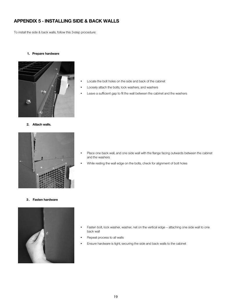
APPENDIX 5 - INSTALLING SIDE & BACK WALLS
To install the side & back walls, follow this 3-step procedure:
3 . Fasten hardware
1. Prepare hardware
2. Attach walls.
• Locate the bolt holes on the side and back of the cabinet
• Loosely attach the bolts, lock washers, and washers
• Leave a sufficient gap to fit the wall between the cabinet and the washers
• Place one back wall, and one side wall with the flange facing outwards between the cabinet and the washers
• While resting the wall edge on the bolts, check for alignment of bolt holes
• Fasten bolt, lock washer, washer, net on the vertical edge – attaching one side wall to one back wall
• Repeat process to all walls
• Ensure hardware is tight, securing the side and back walls to the cabinet

20
NOTES

NOTES
21

NOTES
22

NOTES
23

Visit our Website for more information on this productwww.diversitech.ca
1200 55th Avenue Montreal, Quebec H8T 3J8Email: [email protected]
LIMITED EQUIPMENT WARRANTYFor a period of 2 years from the date of purchase, all Diversitech products are warranted to be free from defects in material, workmanship, and construction, when used in accordance with installation, maintenance instructions, and expressly stated proper use application(s). Diversitech Inc. will repair or replace, at our option, any defective parts which fail during the warranty period. This warranty is limited to replacement parts ONLY, and does not cover personal liability, property loss, normal wear; and does not cover losses resulting from (or due to) improper installation, inadaqueate maintenance, misapplication, misuse, or use above rated capacities.
FREIGHT CLAIMS Shipments must be inspected upon arrival. All Diversitech units are sold ex-plant. Therefore, it is the receiver’s responsibility to file any freight claims with the carrier for obvious or concealed damages. Damaged shipments must be refused at time of receipt, by consignee.
RETURN MATERIAL POLICY Prior to the return of material, for whatever reason, a return manufacturing authorization number (RMA#) is required from the Diversitech customer service department. This procedure is necessary for proper control and handling of returned materials. Call 1-800-361-3733 or email [email protected] to obtain an RMA.
All material must be returned prepaid. Credit will be given for returns for warranty repair or replacement. Freight collect shipments, or freight without an RMA, will not be accepted. It is the shipper’s responsibility to ensure that material being returned to Diversitech is adequately packaged for shipment to preclude damages.


![Research Article ExposureAssessmentinNailSalons ...tional Safety and Health has developed guidance for local exhaust ventilation via downdraft ventilation in nail tables [22]. Our](https://img.dokumen.tips/doc/110x75/609fffc4c65d8b5f0171bebd/research-article-exposureassessmentinnailsalons-tional-safety-and-health-has.jpg)