Embed Size (px)
Citation preview
Vol-3 Issue-3 2017 IJARIIE-ISSN(O)-2395-4396
5742 www.ijariie.com 3682
INDUSTRIAL AND POWER PLANT
WASTE HEAT RECOVERY SYSTEMS
FOR COMBINED COOLING-HEATING
AND POWER GENERATION
Kaushalendra Kumar Dubey#*1
, R. S. Mishra*2
#D/o Mechanical Engineering, Sharda University, UP-201306, India
*D/o Mechanical Engineering, Delhi Technological University, Delhi-110046, India
Abstract- Energy Intensive industries like, cement, steel, glass and metal, etcare responsible for environment‘s severe
impact and high energy prices. Approximately 20-50% of total energy input is dumped into atmosphere from
different industrial process, and this industrial waste heat (IWH) may reuse for clean power generation.
Numerous technologies have been proposed for waste heat recovery (WHR) like Tri-Generation (combined
power, heating and refrigeration effect) system, organic rankine cycle (ORC) based systems, co-generation
systems with solar integrated also. This paper focuses on combined heating-cooling and power generation by
WHR systems with role of new trends of refrigerants.The key benefits of WHRtechnologies are reduce
environment impact, generation of process heating, power and cooling effect with low operating cost and the
employment of renewable energy systems for heat recovery in energy efficient manner for conventional power
plants and industries like steel,cementetc.The waste heat recovery from industries and power plant have
tremendous potential for re-powering of plant and new market opportunities for employment of efficient heat
recovery technology in terms of energy conservation and environment aspect.
Keywords- Tri-Generation, ORC, GWP, ODP, Solar Energy,HRSG,CCHP
I. INTRODUCTION
Nowadays due to 40% predicted increase in energy consumption of the world, more
environmental concerns form of global warming, acid rains, air, water and soil pollution,
ozone depletion, forest devastation and radioactive substances emissions. Utilizing waste heat
attempts to derive energy out of renewable resources as low grade thermal heat sources have
motivated the use of advanced energy recovery systems.The present research issue provides
the concept and employment of low global warming potential (GWP) and ozone depletion
potential (ODP)values type chemicals (refrigerants) based utilities for IWH recovery
application.
II. WASTE HEAT RECOVERY THERMAL SYSTEMS
A. COMBINED AND COGENERATION SYSTEM (HEATING-POWER GENERATION
CONCEPT)-Cogeneration or combined heat and power (CHP) is use to
generate electricity and useful heat or process heat at the same time through coupling
of two different power cycles like gas turbine and steam turbine systems. In power
generation,the production of electricity, some energy must be discarded as waste heat,
but in cogeneration this thermal energy is put to use. Bazques and Strom And
Maidment and Tozer have reviewed a number of combined energy production plants
operating in supermarkets. TheyAnalyzed different schemes of combined energy

Vol-3 Issue-3 2017 IJARIIE-ISSN(O)-2395-4396
5742 www.ijariie.com 3683
production including different cooling and engine technologies [1-2]. BEE [4]
summarized the popularity of topping and bottoming cycle concept of co-generation
system which are suitable for manufacturing processes that require heat at high
temperature in furnaces and kilns, and reject heat at significantly high temperatures.
Typical areas of application include cement, steel, ceramic, gas and petrochemical
industries. Bottoming cycle plants are much less common than topping cycle plants.
The waste gases coming out of the furnace is utilized in a boiler to generate steam,
which drives the turbine to produce electricity.[4,55]
Fig-1: Thermodynamic concept of power-cooling system Fig-2: Combined Power Cycle [55]
B. TRIGENERATION SYSTEM -Tri-generation technology provide simultaneously three
forms of output energy; electrical power, heating and cooling. Trigeneration is also
known as CCHP (Combined Cooling, Heating and Power) or CHRP (Combined
Heating, Refrigeration and Power). In essence, trigeneration systems are CHP
(Combined Heat and Power) or co-generation systems, integrated with a thermally
driven refrigeration system to provide cooling as well as electrical power and heating.
Trigeneration systems can have overall efficiencies as high as 90% compared to 33%-
35% for electricity generated in central power plants. [4,59]
Fig-3: Trigneration System layout [4] Fig-4: ORC components[7]
C. ORGANIC RANKINE CYCLE (ORC)-Chen and Goswami [5] reviewed the different
thermodynamic systems for utilization of discard heat, like Organic Rankine Cycle
(ORC ).The ORC applies the principle of the steam Rankine cycle, but uses organic
working fluid with low boiling points, instead of steam, to recover heat from a lower
temperature source. The cycle consists of an expansion turbine, condenser, a pump, a
boiler and a superheated (provide superheat is needed).Different form of combined
with ORC as a bottoming cycle,ORC with different pure working fluids such as
HCFC123 (CHCl2CF3), PF5050 (CF3(CF2)3CF3), HFC-245fa (CH3CH2CHF2), HFC-

Vol-3 Issue-3 2017 IJARIIE-ISSN(O)-2395-4396
5742 www.ijariie.com 3684
245ca (CF3CHFCH2F), isobutene ((CH3)2C=CH2), n-pentane and aromatic
hydrocarbons, have been studied for organic Rankine cycles. for power plants, cement
industry, desalination, process industry,and manufacturing industry. Working fluid
classified as a Dry fluid, wet fluid or isentropic fluid.Isentropic or dry fluid was
suggested for ORC to avoid liquid droplet impingement in turbine blade during the
expansion. If the fluid is too dry the expanded vapor will leave the turbine with
substantial superheat, which is a waste and add to the cooling load in . The cycle
efficiency can be increased using this superheat to preheat the liquid after it leaves the
feed pump and before it enters the boilers [5,7-10] .All components of ORC shown in
fig-4.
D. BINARY FLUID POWER SYSTEM( KALINAMODEL)-AleksanderKalina developed
binary fluid based power and cooling system in between 1970 and 1980.Kalina cycles
system (KCS) uses ammonia-water (Binary fluid) mixture based working fluidused as
source for power and cooling. In this cycle ammonia is the refrigerent and water as is
the absorbent due to the high difference in their boiling point and high enthalpy. In the
Kalinacycle,the used binary fluid mixture results in a good thermal match in the
boiler due to the non-isothermal boiling created by the shifting mixture
composition.Several studies have shown that the kalina cycle performs substantially
better than a steam Rankine cycle system.A second law analysis showed that by using
a binary fluid,theKalina cycle reduced irreversibility in the boiler,resulting in
improved efficiency of the cycle.One drawback of the Kalina cycle is the fact that
high vapor fraction is needed in the boiler, however, the heat exchanger surface is
easy to dry out at high vapor fractionas,resulting in lower overall heat transfer
coefficients and a larger heat exchange area.Another drawback relates to the
corrosivity ofammonia.Impurities in liquid ammonia such as air or carbon dioxide can
cause stress corrosion cracking of mild steel and also ammonia is highly corrosive
towards copper and zinc [5,29]. Goswami proposed in 1998 [5]a novel
thermodynamic cycle that uses binary mixture to produce power and refrigeration
simultaneously in one loop. This cycle,Fig-5a is a combination of Rankine power and
absorption cooling cycle. The binary mixture first used was ammonia-water and later
on new binary fluids were proposed and studied.
Fig-5a: Goswami Cycle [5] Fig-5b: Schematic of the power-cooling cycle [5]
III. WASTE HEAT ENERGY SOURCES AND TECHNOLOGICAL DEVELOPMENT (Study by TURBODEN, project of centre of science and environment,GOI)

Vol-3 Issue-3 2017 IJARIIE-ISSN(O)-2395-4396
5742 www.ijariie.com 3685
Three categories of wastage heat sources are distinguished with respect to the temperature
level, low (<2300C),medium (230-650 0C) and high (>6500C)[3].Waste heat sites and
thermal levels are listed in table I, and table II explain Indian industrial sector waste heat
recovery survey by TURBODEN.
Table-I: Energy recovery and its sources [3,6]
Heat Categories Heat Sources Temperature in 0C Suggested recovery technology
High Grade (>6500C)
Solid waste 650-1000 Air preheating
Nickel refining furnace 1370-1650 Steam generation for heating
Copper reverberatory furnace 760-815 Thermoelectric and thermal PV
Glass melting furnace 1000-1550 Heat exchanger for preheating
Hydrogen plant 650-1000 Thermal PV
Medium Grade (230-
6500C)
Steam boiler exhaust 230-480 Steam rankine cycle
Gas turbine exhaust 370-540 Organic rankine cycle
Drying and baking ovens 230-600 Thermal PV
Catalytic crackers 425-650 Thermal PV
Reciprocating engine exhaust 315-600 Thermoelectric
Low Grade (>2300C)
Welding and injection molding 32-88 Kalina cycle
Hot processed liquids and solids 32-233 Organic rankine cycle
Drying,Baking and Curing ovens 93-230 Absorption and adsorption cooling
Bearing 32-88 Piezoelectric
Table-II: Waste Heat Energy recovery in Indian Industrial Sector survey[3]
Cement Industry Glass Industry
Iron and Steel Industry
According to a study done by TURBODEN
(one of the market leaders in ORC technology), a 2,500 ton per day plant of
cement can be used to set up a 1.6 MW.
waste heat recovery plant using the Organic Rankine Cycle. Based on this assumption
and projected manufacturing capacity of
cement industry in India, a rough potential of the electricity production from waste heat
by ORC technology is estimated to be 574
MW
Typically, a 500 ton per day glass
manufacturing plant will have potential for a 1 MW Organic Rankine Cycle waste heat
recovery plant. The projected waste heat
recovery potential through ORC in the glass industry in India is total potential estimated
at around 36 MW by 2017
Typically, a 6,000 ton per day steel rolling
mill has a potential of generating 2.4 MW of electricity through an Organic Rankine
Cycle waste heat recovery plant. The
projected waste heat recovery potential through ORC in the Iron and Steel sector is
total potential estimated to be around 148.4
MW by 2017
3.1 GLOBAL AND INDIA MARKET OF WHR
There are over 850 WHR power installations in the world shown in Fig-6. China leads in the
number of WHR installations—739, followed by India (26 WHR installations) and Japan (24
installations) [61].
Fig-6: Global WHR Power Stations Fig-7: WHR in Eleven countries
(Source File-http://www.iipnetwork.org/62730%20WRH_Report.pdf2)

Vol-3 Issue-3 2017 IJARIIE-ISSN(O)-2395-4396
5742 www.ijariie.com 3686
The eleven countries were selected based on the robustness of their respective cement
industries and cement markets, relative prospects for near and mid-term growth in their
economies and cement consumption, and market factors that would drive consideration of
WHR such as power reliability concerns, industrial electricity tariffs and environmental and
sustainability initiatives. Figure-7 provides a summary of the market review of eleven
countries in terms of WHR potential [61].
3.2 WHR COMPANIES WORKS IN INDIA
Transparent Energy Systems Private Limited is an Indian engineering and construction
firm that has developed and patented an in-house technology for waste heat recovery systems
for the cement industry. Tecpro Systems Limited is an Indian engineering, procurement and
construction contractor active in the power sector including captive power plants for the
Indian cement industry. In February 2011 Tecpro entered into a collaborative agreement with
Nanjing Triumph Kaineng Environment and Energy Company to develop waste heat power
projects for the Indian market. Thermax is an Indian supplier and engineering/constructor of
energy systems including boilers and steam systems. Thermax entered into an agreement with
Taiheiyo Engineering Corp ofJapan (a subsidiary of Taiheiyo Cement) to offer waste heat
recovery power generation systems in India. The collaborative has two systems at JK
Cement, Nimbahera and at JK Lakshmi [60-61].The installed capacity of heat recovery power
generation systems for industry and renewable energy sources both in India using ORC
described in table-III. Table-III:ORC Development in India [61]
Sector Capacity (MW)
1. Wastage Heat Recovery In Major Industry
a. Cement 574.2
b. Glass 35.7
c. Iron and steel 148.4
Total 758.3
2.Renewable Energy
a. Solar thermal energy storage 1440
b. Biogas plant 2208
c. Geothermal NA
Total 3648
Grand Total 4406.3
IV. RESEARCH OVERVIEW ON WHR SYSTEMS
Present Literature review focus on low grade energy recovery systems, working fluid and
their selection criteria with fluid properties and technological development. The working
fluid is one of the most important components of a Rankine cycle power system. Intense
research of non-geothermal ORC use took place in this country during the early 1970‘s
through the early 1980‘s. ORC heat engines were reconsidered for utilizing solar resources
and conserving other resources by recovering energy from waste heat. In one an ORC was
integrated with a large truck engine to recover heat from the exhaust and save on fuel costs
with the idea of replacing the automobile internal combustion engine with an ORC system
was explored [16-17]. Mechanical cooling systems were one of the more productive research
areas that dealt with the conversion of solar thermal energy. A significant amount of the
publishedliterature regarding ORC conversion of solar thermal energy comes from this and
related work [18]. The concept started as an alternative to solar-driven, absorption, air
conditioning cycles which have a limited coefficient of performance. Essentially, mechanical

Vol-3 Issue-3 2017 IJARIIE-ISSN(O)-2395-4396
5742 www.ijariie.com 3687
work produced by a solar-driven ORC would be used to drive vaporcompression air
conditioning equipment, with the potential of a higher COP than absorption equipment [18-
20]. As for ORC technology today, it has found some niche successes in geothermal
utilization, biomass utilization, some industrial heat recovery, and cathodic protection of
pipelines, as judged by a few manufacturer‘sportfolios. More recent research in the area has
largely taken place internationally [21-24]. Two approaches have been noted: one is to
develop and design systems around high-speed turbo-machinery with a shaft integral
generator and circulation pump , thus reducing costs by simpler design, and the other, more
recent idea is to adapt mass-produced (cheap) displacement compressors for use as
reasonably efficient expanders [24-27]. The lineage that the power cooling cycle is derived
from initially intended for utility-scale bottoming cycle duty. The first study of an absorption
based power cycle was performed by Maloney and Robertson who concluded no significant
advantage to the configuration. Several decades later, Kalina reintroduced the idea of an
ammonia-water power cycle as a superior bottoming cycle option over steam Rankine cycles
[28-31].Theammonia-water based power cycles have been proposed for solar utilization,
geothermal, ocean thermal energy conversion, and other forms of heat recovery. While it was
the interest brought about by Kalina‘s proposal that led to the introduction of the power-
cooling cycle, it is somewhat ironic that the original suggestion for its implementation is
more similar to the original Maloney-Robertson implementation [7,8].Referring to Fig-
5a&5b of power-cooling cycle, basic solution fluid is drawn from the absorber and pumped
to high pressure via the solution pump. Before entering the boiler, the basic solution recovers
heat from the returning weak solution in the recovery heat exchanger.In the boiler, the basic
solution is partially boiled to produce a two-phase mixture; a liquid, which is relatively weak
in ammonia, and a vapor with a high concentration of ammonia. This two-phase mixture is
separated and the weak liquid is throttled back to the absorber. The vapor‘s ammonia
concentration is increased by cooling and condensate separation in the rectifier. Heat can be
added in the superheater as the vapor proceeds to the expander, where energy is extracted
from the high-pressure vapor as it is throttled to the system low-pressure. The vapor rejoins
the weak liquid in the absorber where, with heat rejection, the basic solution is regenerated.
[32-34]. Later studies concluded that the cycle could be optimized for work or cooling
outputs and even for efficiency. Optimization studies began to appear, optimizing on the
basis of various efficiency definitions, minimum cooling temperature, working fluid
combination, and system configuration. Also, an experimental study was described byTamm
and Goswami [10] which generally verified the expected boiling and absorption processes.
Goswami and Xu [33] presented the first theoretical analysis of the power-coolingcycle.
Turbine inlet temperatures of 400 – 500 K were considered along with absorption
temperatures of 280 – 320 K. Cooling production suffered with increased turbine inlet and
absorption temperatures, and benefited with increased boiler pressure. Many of the operating
trends of importance in this work were introduced here. Optimization studies began to appear
following this work, which identified the balance of effects that dictate cycle operation. Lu
and Goswami [8] optimized the ideal cycle conditions using various objectives, work output,
cooling output, first and second law efficiencies. All operating parameters, efficiencies,
power/cooling output, etc., were found to decrease with increasing heat rejection
temperatures. At high heat source temperatures, 440 K, no cooling was possible at conditions
optimized for second lawefficiency. A contrast between work optimized and cooling
optimized cases was provided. Important differences in the cooling optimized case versus the
work optimized one were higher vapor concentration, lower turbine inlet temperature, low
vaporization fraction (16.5 % vs. 91.2 %), and a lower basic solution concentration.
Minimum cooling temperatures were also optimized, and a minimum turbine exhaust
temperature of 205 K was identified under the assumptions considered [35]. The appropriate
Vol-3 Issue-3 2017 IJARIIE-ISSN(O)-2395-4396
5742 www.ijariie.com 3688
efficiency expressions for the cycle was tackled by Vijayaraghavan and Goswami [36].
Vijayaraghavan, et al introduced a satisfactory second law efficiency definition based upon
ideal Lorenz cycle performance which accounts for sensible heat addition and rejection
behavior. However, they concede that ultimately the value of work and cooling will be
decided by the end application .Both first and second law efficiency analyses were performed
for the cycle. A second law efficiency of 65.8 % was determined [36-38].The idealized model
considered for largest source of irreversibility was found to be the absorber at all conditions
considered; while at higher heat source temperatures the rectifier also contributed
significantly less-than-ideal modeling began with Tamm et al, in preparation for the initial
experimental studies [10,39-40]. The largest deviation from idealized simulations was due to
the non-isentropic performance of the turbine. This relates well to the findings of Badr et al.
,who identified the expander isentropic efficiency as the single-most influential factor
affecting overall ORC engine performance. Initial experimentation was reported [41-42];
however, turbine operation was simulated by an expansion valve and a heat exchanger.
General boiling condition trends were demonstrated, for example vapor mass flow fraction,
vapor concentration, and boiler heat transfer. Vapor production was less than expected and
improvements to the setup were identified and implemented. Performance of the new
configuration, still having a simulated turbine, was also reported [10].Vapor production and
absorption processes were experimentally shown, and independent study of the power-
cooling concept has been provided by Vidal et al [43].
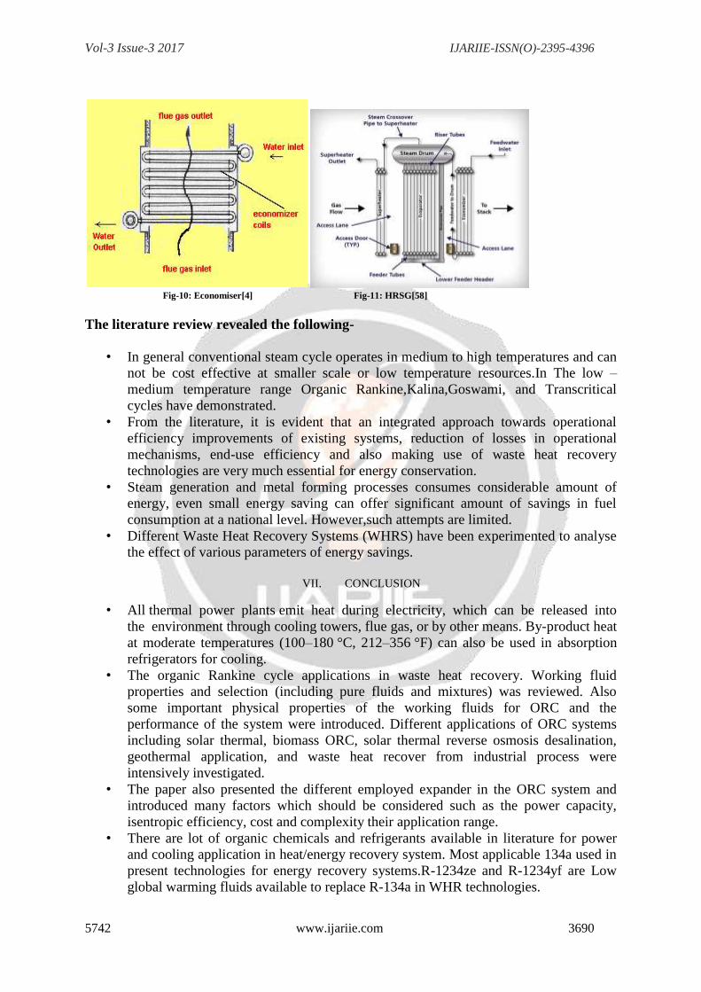
V. OVERVIEW ON WORKING FLUIDS
Steam has shown its ability to serve as working fluid in high temperature power plants. In
low temperature ( ≤200 ºC) or low-output power plants ( ≤10 kW), the use of water is not
economically feasible [44-45]. Therefore, other fluids should be sought. Interest was found
for refrigerants and some other fluids. These fluids are: Halons, hydrocarbons (HCs),
hydrofluorocarbons (HFCs), chlorofluorocarbons (CFCs), hydrochlorofluorocarbons
(HCFCs) and natural fluids like carbon dioxide, ammonia, air, etc. Unfortunately, some of the
above categories of fluids were phased-out or are to be banned soon by the international
regulations, manufacturers of refrigerants, and researchers to look for new environmentally
friendly fluids. So, new categories of fluids like zeotropes, azeotropes and other multi
component fluids were born [46-47,56,57].The choice of the working fluid is very important
as it determines the efficiency and the economics of WHR technological development on the
basis of thermal properties like critical pressure, boiling point, specific volume, molecular
weight,compatibility with material and environment safety tools GWP and ODP values [48-
53].There are different sets of experiment done by the different scientist or scholars and they
find the property of the working fluid which is shown in table-IV.
Table IV: Summary of Commercialized Working fluids [36,44-45,48-54]
S.N
o
Chemicals Physical Data Safety Data Environmental Data
Molecular
Mass
(Kg/K
mol)
Normal
Boiling Point
Temp (Tbp)
in 0C
Critical
Temp
(Tcriti) in 0C
Critical
Pressur
e (Pcriti)
in MPa
ASHRAE
Group
Atmospheri
c Life Time
(ALT) in
years
Ozone
Depletion
potential
(ODP)
Global Warming
Potential (GWP)
of 100 years
1 RC118 200.03 -6.0 115.2 2.778 A1 3200 0 10225
2 R600a 58.12 -11.7 135 3.647 A3 0.017 0 ˜˜20
3 R114 170.92 3.6 145.7 3.289 A1 300 1.00 10040
4 R600 58.12 -0.5 152 3.796 A3 0.018 0 ˜˜20
5 R601 72.15 36.1 196.5 3.364 NA 0.01 0 ˜˜20
6 R113 187.38 47.6 214.1 3.439 A1 85 1.000 6130
7 Cyclohexane 84.16 80.7 280.5 4.075 A3 NA NA NA

Vol-3 Issue-3 2017 IJARIIE-ISSN(O)-2395-4396
5742 www.ijariie.com 3689
`
8 R290 44.10 -42.1 96.68 4.247 A3 0.041 0 ~20
9 R407C 86.20 -43.6 86.79 4.597 A1 NA 0 1800
10 R32 52.02 -51.7 78.11 5.784 A2 4.9 0 675
11 R500 99.30 -33.0 105.5 4.455 A1 NA 0.738 8100
12 R152a 66.05 -24.0 113.3 4.520 A2 1.40 0 124
13 R717
(Amonia)
17.03 -33.3 132.3 11.333 B2 0.1 0 <1
14 Ethanol 46.07 78.4 240.8 6.148 NA NA NA NA
15 Methanol 32.04 64.4 240.2 8.104 NA NA NA NA
16 R718
(Water)
10.2 100 374 22.064 A1 NA 0 <1
17 R134a 102.03 -26.1 101 4.059 A1 14.0 0 1430
18 R12 120.91 -29.8 112 4.114 A1 100 1.000 10890
19 R123 152.93 27.8 183.7 3.668 B1 1.3 0.02 77
20 R141b 116.95 32.0 204.2 4.249 NA 9.3 0.120 725
21 R245fa 134.05 15.3 154.1 3.64 B1 8.8 0 820
22 R236fa 152.0 -1.5 124.0 3.20 - 209 0 6300
23 R227ea 170.0 -17.5 102.0 2.95 - 36.5 0 2900
24 R1234yf 114.02 -29.45 94.7 3.382 A1 NA ~0 4
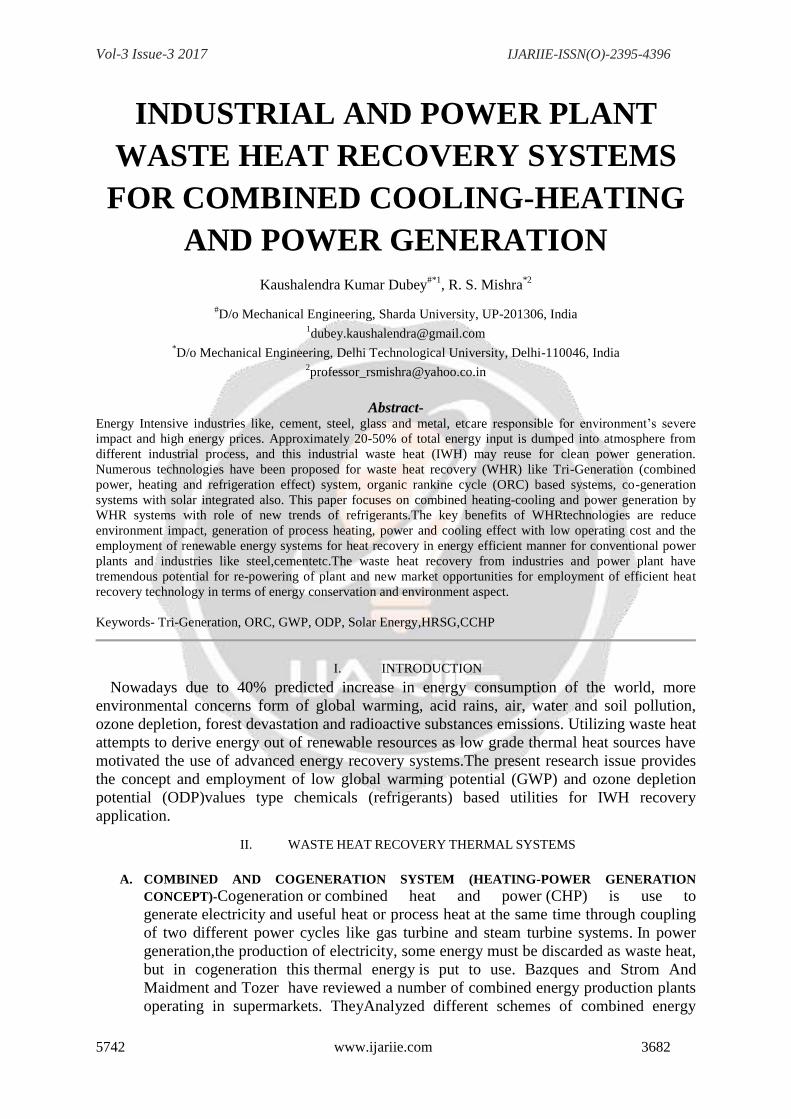
VI. COMMERCIAL WASTE HEAT RECOVERY SYSTEM
A recuperator, recovering waste heat from flue gases, the heat exchange takes place
between the flue gases and the air through metallic or ceramic walls. Duct or tubes carry the
air for combustion to be pre-heated, the other side contains the waste heat stream. Heat pipe
is a thermal energy absorbing and transferring system and have no moving parts and hence
require minimum maintenance. Heat pipe can transfer up to 100 times more thermal energy
than copper. The heat pipe heat recovery systems are capable of operating at 315o
C with 60%
to 80% heat recovery capability. Economizer provides to utilize the flue gas heat for pre-
heating the boiler feed water in boiler. On the other hand, in an air pre-heater, the waste heat
is used to heat combustion air. In both the cases, there is a corresponding reduction in the fuel
requirements of the boiler. For every 220
C reduction in flue gas temperature by passing
through an economiser or a pre-heater, there is 1% saving of fuel in the boiler. For every 60
C
rise in feed water temperature through an economiser or 200
C rise in combustion air
temperature through an air pre-heater, there is 1% saving of fuel in the boiler unit. Heat
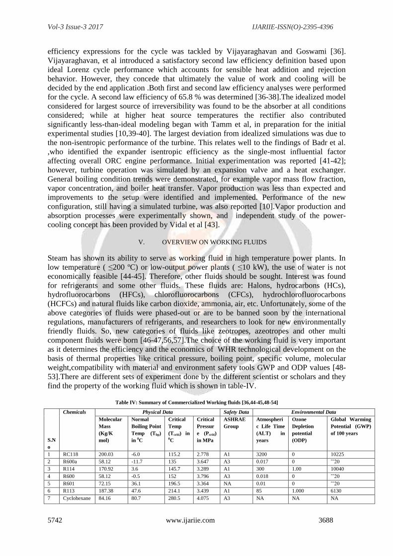
Recovery Steam Generator is an energy recovery heat exchanger that recovers heat from a
hot gas stream. It produces steam that can be used in a process (cogeneration) or used to drive
a steam turbine (combined cycle). HRSG provides the thermodynamic link between the gas
turbines and steam turbines in a combined-cycle power plant. All units shown in fig-
8,9,10,11.
Fig-8: Heat Pipe Exchanger [4] Fig-9: Recuperator [4]
Vol-3 Issue-3 2017 IJARIIE-ISSN(O)-2395-4396
5742 www.ijariie.com 3690
Fig-10: Economiser[4] Fig-11: HRSG[58]
The literature review revealed the following-
• In general conventional steam cycle operates in medium to high temperatures and can
not be cost effective at smaller scale or low temperature resources.In The low –
medium temperature range Organic Rankine,Kalina,Goswami, and Transcritical
cycles have demonstrated.
• From the literature, it is evident that an integrated approach towards operational
efficiency improvements of existing systems, reduction of losses in operational
mechanisms, end-use efficiency and also making use of waste heat recovery
technologies are very much essential for energy conservation.
• Steam generation and metal forming processes consumes considerable amount of
energy, even small energy saving can offer significant amount of savings in fuel
consumption at a national level. However,such attempts are limited.
• Different Waste Heat Recovery Systems (WHRS) have been experimented to analyse
the effect of various parameters of energy savings.
VII. CONCLUSION
• All thermal power plants emit heat during electricity, which can be released into
the environment through cooling towers, flue gas, or by other means. By-product heat
at moderate temperatures (100–180 °C, 212–356 °F) can also be used in absorption
refrigerators for cooling.
• The organic Rankine cycle applications in waste heat recovery. Working fluid
properties and selection (including pure fluids and mixtures) was reviewed. Also
some important physical properties of the working fluids for ORC and the
performance of the system were introduced. Different applications of ORC systems
including solar thermal, biomass ORC, solar thermal reverse osmosis desalination,
geothermal application, and waste heat recover from industrial process were
intensively investigated.
• The paper also presented the different employed expander in the ORC system and
introduced many factors which should be considered such as the power capacity,
isentropic efficiency, cost and complexity their application range.
• There are lot of organic chemicals and refrigerants available in literature for power
and cooling application in heat/energy recovery system. Most applicable 134a used in
present technologies for energy recovery systems.R-1234ze and R-1234yf are Low
global warming fluids available to replace R-134a in WHR technologies.

Vol-3 Issue-3 2017 IJARIIE-ISSN(O)-2395-4396
5742 www.ijariie.com 3691
• Increased reliability and security of energy supply. Lower energy cost: the 75 %
saving ofoperation cost compared to conventional unit and higher overall efficiency:
24 % higher than conventional unit.Fuel energy losses reduced to approximately 4 %
as against around 28 % in case ofconventional system.
• The waste heat recovery from industries and power plant have huge potential for re-
powering of plant and new market scope for employment of efficient heat recovery
technology in respect of energy conservation and environment aspect.
ABBREVIATIONS
CHP-Combined Heat and Power
CCHP- Combined Cooling-Heat and Power
CHRP- Combined Heat Refrigeration and Power
GWP-Global Warming Potential
HRSG-Heat Recovery Steam Generator
IWH-Industrial Waste Heat
KCS-Kalina Cycle System
ORC-Organic Rankine Cycle
ODP-Ozone Depletion Potential
WHR-Waste Heat Recovery
REFERENCES
[1] E. Bazques, D. Strom, Cogeneration and interconnection technologies for industrial and
commercial use, in:Proceedings of 18th IECEC American Institute of Chemical Engineers,
1983, pp. 2060–2065.
[2] G.G. Maidment, R.M. Tozer, Combined cooling heat and power in supermarkets, Applied
Thermal Engineering22 (2002) 653–665.
[3]TURBDONE report 2013, Govt of India.
[4] https://beeindia.gov.in/sites/default/files/2Ch8.pdf
[5] Chen H, Goswami DY, Stefanakos EK. A review of thermodynamic cycles and working
fluids for the conversion of low-grade heat. Renewable and Sustainable Energy Reviews
2010;14:3059–67.
[6] http://www.ormat.com.
[7] Goswami, D. Y., 1995, ―Solar Thermal Power: Status of Technologies and Opportunities
for Research,‖ Heat and Mass Transfer ’95, Proceedings of the 2nd
ASME-ISHMT Heat and
Mass Transfer Conference, Tata-McGraw Hill Publishers, New Delhi, India, pp. 57-60.
[8] Lu, S., and D. Y. Goswami, 2003, ―Optimization of a Novel Combined
Power/Refrigeration Thermodynamic Cycle,‖ Journal of Solar EnergyEngineering, 125, pp.
212-217.
[9] Tamm, G., D. Y. Goswami, S. Lu, and A. A. Hasan, 2003, ―Novel Combined Power and
Cooling Thermodynamic Cycle for Low Temperature Heat Sources, Part I: Theoretical
Investigation,‖ Journal of Solar Energy Engineering, 125, pp. 218-222.
[10] Tamm, G., and D. Y. Goswami, 2003, ―Novel Combined Power and Cooling
Thermodynamic Cycle for Low Temperature Heat Sources, Part II: Experimental
Investigation,‖ Journal of Solar Energy Engineering, 125, pp. 223-229.
[11] Vijayaraghavan, S., 2003, ―Thermodynamic Studies on Alternate Binary Working Fluid
Combinations and Configurations for a Combined Power and Cooling Cycle,‖ Ph.D.
dissertation, University of Florida, Gainesville, FL.
[12] Dunn, S., 2000, ―Micropower: The Next Electrical Era,‖ Worldwatch Paper, 151,July,
94p.
[13] Thermally Activated Technologies: Technology Roadmap—Developing New Ways to
Use Thermal Energy to Meet the Needs of Homes, Offices, Factories, and Communities,
2003, Office of Energy Efficiency and Renewable Energy, U. S. Dept. of Energy, 46p.

Vol-3 Issue-3 2017 IJARIIE-ISSN(O)-2395-4396
5742 www.ijariie.com 3692
Available at: http://www.eere.energy.gov/de/pdfs/tat_roadmap.pdf, last accessed October
23,2004.
[14] Butti, K., and J. Perlin, 1980, A Golden Thread, Van Nostrand Reinhold Co.New York.9
[15] Wahl, E. F., 1977, Geothermal Energy Utilization, John Wiley & Sons, New York.
[16] Patel, P. S., and E. F. Doyle, 1976, ―Compounding the Truck Diesel Engine with an
Organic Rankine-Cycle System,‖ SAE publication 760343, 12p.150
[17] Lindsley, E. F., 1970, ―New: Minto‘s Unique Steamless ‗Steam‘ Car,‖ Popular Science,
Oct, pp. 51-53.
[18] Curran, H. M., 1988, ―Mechanical Systems and Components,‖ Active Solar Systems,
Vol. 6, G. Löf ed. MIT Press, Cambridge, MA.
[19] Prigmore, D., and R. E. Barber, 1975, ―Cooling with the Sun‘s Heat: Design
Considerations and Test Data for a Rankine Cycle Prototype,‖ Solar Energy, 17,pp. 185-192.
[20] Barber, R. E., 1978, ―Current Costs of Solar Powered Organic Rankine Cycle Engines,‖
Solar Energy, 20, pp.1-6.
[21] Yamamoto, T. T. Furuhata, N. Arai, and K. Mori, 2001, ―Design and Testing of the
Organic Rankine Cycle,‖ Energy, 26, pp. 239-251.
[22] Angelino, M., M. Gaia, and E. Macchi, 1984, ―A Review of Italian Activity in the Field
of Organic Rankine Cycles,‖ VDI Berichte 539, pp. 465-482.
[23] Nguyen, T., P. Johnson, A. Akbarzadeh, K. Gibson, and M. Mochizuki, 1995, ―Design,
Manufacture and Testing of a Closed Cycle ThermosyphonRankine Engine,‖ Heat Recovery
Systems & CHP, 15 (4), pp. 333-346.
[24] Kane, M., D. Larrain, D. Favrat, and Y. Allani, 2003, ―Small Hybrid Solar Power
System,‖ Energy, 28, pp. 1427-1443.
[25] Larjola, J, 1995, ―Electricity From Industrial Waste Heat Using High-Speed Organic
Rankine Cycle (ORC),‖ International Journal of Production Economics, 41, pp. 227-235.
[26] Smith, T. C. B., 2003, ―Low Cost Organic Rankine Cycles for Grid Connected Power
Generation,‖ Proceedings of the ISES Solar World Congress, Göteborg, Sweden,
International Solar Energy Society, 8 p.
[27] Wells, D. N., 2000. ―Scroll Expansion Machines for Solar Power and Cooling Systems,‖
Proceedings of Solar 2000, Madison, WI, American Society of Mechanical Engineers, 7p.
[28] Maloney, J. D., and R. C. Robertson, 1953, ―Thermodynamic Study of Ammonia- Water
Heat Power Cycles,‖ ORNL Report CF-53-8-43, Oak Ridge, TN.
[29] Kalina, A. I., 1984, ―Combined Cycle System with Novel Bottoming Cycle,‖ ASME
Journal of Engineering for Gas Turbines and Power, 106, pp. 737-742.
[30] Marston, C. H., 1990, ―Parametric Analysis of the Kalina Cycle,‖ Journal of
Engineering for Gas Turbines and Power, 112, pp. 107-116.151
[31] Ibrahim, O. M., and S. A. Klein, 1996, ―Absorption Power Cycles,‖ Energy, 21, (1), pp.
21 27.
[32] Xu, F., and D. Y. Goswami, 1999, ―Thermodynamic Properties of Ammonia-Water
Mixtures for Power-Cycle Applications,‖ Energy, 24, pp. 525-536.
[33] Goswami, D. Y., and F. Xu, 1999, ―Analysis of a New Thermodynamic Cycle for
Combined Power and Cooling Using Low and Mid Temperature Solar Collectors,‖ Journal
of Solar Energy Engineering, 121, pp. 91-97.
[34] Xu, F., D. Y. Goswami, and S. S. Bhagwat, 2000, ―A Combined Power/Cooling Cycle,‖
Energy, 25, pp. 233-246.
[35] Lu, S., and D. Y. Goswami, 2002, ―Theoretical Analysis of Ammonia-Based
Combined Power/Refrigeration Cycle at Low Refrigeration Temperatures,‖ Reno, NV,
Proceedings of SOLAR 2002, American Society of Mechanical Engineers, 9p.

Vol-3 Issue-3 2017 IJARIIE-ISSN(O)-2395-4396
5742 www.ijariie.com 3693
[36] Vijayaraghavan, S., and D. Y. Goswami, 2002, ―On Evaluating Efficiency of a
Combined Power and Cooling Cycle,‖ New Orleans, LA, Proceedings of IMECE2002,
American Society of Mechanical Engineers, 9 p.
[37] Hasan, A. A., D. Y. Goswami, and S. Vijayaraghavan, 2002, ―First and Second Law
Analysis of a New Power and Refrigeration Thermodynamic Cycle Using a Solar Heat
Source,‖ Solar Energy, 73 (5), pp. 385-393.
[38] Hasan, A. A., and D. Y. Goswami, 2003, ―Exergy Analysis of a Combined Power and
Refrigeration Thermodynamic Cycle Driven by a Solar Heat Source,‖ Journalof Solar
Energy Engineering, 125, pp. 55-60.
[39] Tamm, G., D. Y. Goswami, S. Lu, and A. A. Hasan, 2004, ―Theoretical and
Experimental Investigation of an Ammonia-Water Power and Refrigeration Thermodynamic
Cycle,‖ Solar Energy, 76, pp. 217-228.
[40] Tamm, G., D. Y. Goswami, S. Lu, and A. A. Hasan, 2003, ―Novel Combined Power and
Cooling Thermodynamic Cycle for Low Temperature Heat Sources, Part I: Theoretical
Investigation,‖ Journal of Solar Energy Engineering, 125, pp. 218-222.
[41] Badr, O., P. W. O‘Callaghan, and S. D. Probert, 1984, ―Performances of Rankine- Cycle
Engines as Functions of Their Expander‘s Efficiencies,‖ Applied Energy, 18, pp.15-27.
[42] Tamm, G., D. Y. Goswami, S. Lu, and A. A. Hasan, 2001, ―Theoretical and
Experimental Investigation of an Ammonia-Water Power and Refrigeration Thermodynamic
Cycle,‖ Adelaide, Australia, Proceedings of ISES 2001 SolarWorld Congress, International
Solar Energy Society, pp. 893-906.
[43] Vidal, A., R. Best, R. Rivero, and J. Cervantes, 2004, ―Analysis of a Combined Power
and Refrigeration Cycle by the Exergy Method,‖ Energy-Efficient, Cost-Effective, and
Environmentally-Sustainable Systems and Processes (Proceedings of ECOS 2004), R.
Rivero, L. Monroy, R. Pulido, and G. Tsatsaronis, eds.,InstitutoMexicano del Petroleo, 3, pp.
1207-1218.
[44] O. Badr, S.D Probert and P.W. O‘Callaghan, Selecting a working fluid for a Rankine-
cycle engine, Applied Energy 21 (1985) 1-42.
[45] W. B. Stine and M. Geyer, Power cycles for electricity generation, In power from the
sun, 2001. <http://www.powerfromthesun.net/chapter12/chapter12.new.htm> [July 2008]
[46] R.L. Powell, CFC phase-out: Have we met the challenge? Journal of Fluorine Chemistry
114 (2002)237-250.
[47] G. Angelino and P. Colonna di Paliano, Multicomponent working fluids for organic
Rankine cycles(ORCs), Energy 23 (1998) 449-463.
[48] M.J. Lee, D.L. Tien, C.T. Shao, Thermophysical capability of ozone-safe working fluids
for anorganicrankine cycle system, Heat Recovery Systems & CHP 13 (1993) 409-418.
[49] V. Maizza, A. Maizza, Working fluids in non-steady flows for waste energy recovery
systems,Applied Thermal Energy 16 (1996) 579-590.
[50] H. Yamaguchi, X.R. Zhang, K. Fujima, M. Enomoto, N. Sawada, Solar energy powered
Rankinecycle using supercritical CO2, Applied Thermal Engineering 26 (2006) 2345-2354.
[51] EzzatWali, Working fluids for solar, rankine cycle cooling systems, Energy 5 (1980)
631-639.
[52] L. Calderazzi and P. Colonna di Paliano, Thermal stability of R-134a, R141b, R13I1,
R7146, R125assiociated with stainless steel as a containing material, International Journal of
Refrigeration 20 (1997) 381-389.
[53] G. Angelino, C. Invernizzi, Experimental investigation on the thermal stability of some
new zero- ODP refrigerants, International Journal of Refrigeration 26 (2003) 51-58.
[54] Kyoto Protocol to the United Nations Framework Convention on Climate Change,
United Nations,1998.

Vol-3 Issue-3 2017 IJARIIE-ISSN(O)-2395-4396
5742 www.ijariie.com 3694
[55]Yunus A. Cengel, Michael A. Boles, Thermodynamics: An Engineering Approach, 4th
edition,McGraw-Hill, 2002.
[56]U. Drescher, D. Bruggemann, Fluid selection for the organic Rankine cycle (ORC) in
biomasspower and heat plants, Applied Thermal Engineering 27 (2007) 223-228.
[57]H. D. MadhawaHettiarachchi, MihaljoGolubovic, William M. Worek, Yasuyuki Ikegami,
Optimum design criteria for an organic Rankine cycle using low-temperature geothermal heat
sources,Energy 32 (2007) 1698-1706.
[58] https://powergen.gepower.com/products/hrsg.html
[59]Renewable Energy Institute: Trigeneration Technologies Available. [online], [cited: June
2011], Available on internet< http://www.trigeneration.com/ >
[60] http://www.iipnetwork.org/62730%20WRH_Report.pdf2.
[61] Indian Ministry of Industry and Commerce (IMIC), 2011, Report of the Working Group
on Cement Industry for XII Five Year Plan, December 2011
Authors Detail-
Prof.(Dr.) R.S. Mishra Ph.D-SOLAR ENERGY IIT DELHI-
1986., HOD Mechanical Engg in Delhi Technological
University,Delhi,India . He has published more than 250
research papers in repute journals & conferences and also
written 55 books on ASTROLOGY, VADIC Sciences, FENG
SHUAI. Professor Mishra is dynamic personality of area of
solar thermal system design-development and advanced
refrigeration techniques.
Kaushalendra K Dubey is associated with is
the Dept of Mechanical
Engineering,ShardaUniversity,Greater Noida,India as
assistant professor. He is a research fellow of Delhi
Technological University,Delhi,India. Author qualification is
Master of technology in Thermal Engineering with honor's
from Jamia Millia Islamia, Delhi, India..He has faculty
research fellowship from Indian Institute of
Technology,Delhi in 2016 in Energy and Heat Recovery
Research. Author has published more than 25 research
papers in repute journals and conferences and active
volunteer for work on energy research and technology
through industrial and academic project