Embed Size (px)
Citation preview

Part Number 02250118---200eSullair Corporation
OPERATOR’SMANUAL ANDPARTS LIST
KEEP FORFUTURE
REFERENCE
25, 30 & 40 HP
INDUSTRIAL AIRCOMPRESSOR
LS---10
STANDARD & 24 KT18, 22 & 30 KW
AIR---COOLED AND WATER---COOLED
AIR CARESEMINAR TRAINING
Sullair Air Care Seminars are 3--day courses that provide hands--on instructionin the proper operation, maintenance and service of Sullair equipment.Individual seminars on Industrial compressors and compressor electricalsystems are presented at regular intervals throughout the year at a dedicatedtraining facility at Sullair’s corporate headquarters in Michigan City, Indiana.
Instruction includes discussion of the function and installation of Sullair serviceparts, troubleshooting of the most common problems, and actual equipmentoperation. The seminars are recommended for maintenance and servicepersonnel.
For detailed course outlines, schedule and cost information contact:
Sullair Corporate Training Department1--888--SULLAIR or 219--879--5451 (ext. 5363)
-- Or Write --Sullair Corporation3700 E. Michigan Blvd.Michigan City, IN 46360Attn: Service Training Department

TABLE OF CONTENTS
Section 1 PAGE
SAFETY 1 1.1 GENERAL
1 1.2 PERSONAL PROTECTIVE EQUIPMENT
1 1.3 PRESSURE RELEASE
2 1.4 FIRE AND EXPLOSION
2 1.5 MOVING PARTS
2 1.6 HOT SURFACES, SHARP EDGES AND SHARP CORNERS
2 1.7 TOXIC AND IRRITATING SUBSTANCES
3 1.8 ELECTRICAL SHOCK
3 1.9 LIFTING
4 1.10 ENTRAPMENT
Section 2DESCRIPTION 5 2.1 INTRODUCTION
5 2.2 DESCRIPTION OF COMPONENTS
5 2.3 SULLAIR COMPRESSOR UNIT,FUNCTIONAL DESCRIPTION
6 2.4 COMPRESSOR COOLING AND LUBRICATIONSYSTEM, FUNCTIONAL DESCRIPTION
9 2.5 COMPRESSOR DISCHARGE SYSTEM,FUNCTIONAL DESCRIPTION
9 2.6 CONTROL SYSTEM, FUNCTIONAL DESCRIPTION--STANDARD ELECTRO-MECHANICAL
11 2.7 CONTROL SYSTEM, FUNCTIONAL DESCRIPTION--SUPERVISOR II
12 2.8 AIR INLET SYSTEM, FUNCTIONAL DESCRIPTION
12 2.9 INSTRUMENT PANEL GROUP, FUNCTIONALDESCRIPTION-- STANDARD ELECTRO-MECHANICALCONTROLLER
Section 3SPECIFICATIONS 15 3.1 TABLE OF SPECIFICATIONS
16 3.2 LUBRICATION GUIDE
16 3.3 APPLICATION GUIDE
17 3.4 LUBRICATION CHANGE RECOMMENDATIONS ANDMAINTENANCE
Section 4INSTALLATION 21 4.1 MOUNTING OF COMPRESSOR
21 4.2 VENTILATION AND COOLING
21 4.3 SERVICE AIR PIPING
22 4.4 COUPLING ALIGNMENT CHECK
22 4.5 FLUID LEVEL CHECK
22 4.6 ELECTRICAL PREPARATION-- STANDARD ELECTRO-MECHANICAL

TABLE OF CONTENTS(CONTINUED)
Section 4 PAGE
INSTALLATION 23 4.7 ELECTRICAL PREPARATION-- SUPERVISOR II
(CONTINUED) 23 4.8 MOTOR ROTATION DIRECTION CHECK
Section 5OPERATION- 25 5.1 GENERAL
ELECTRO-MECHANICAL 25 5.2 PURPOSE OF CONTROLS-- STANDARD ELECTRO-MECHANICAL
27 5.3 INITIAL START--UP PROCEDURE-- STANDARD ELECTRO-MECHANICAL
27 5.4 SUBSEQUENT START--UP PROCEDURE-- STANDARD ELECTRO-MECHANICAL
27 5.5 SHUTDOWN PROCEDURE-- STANDARD ELECTRO-MECHANICAL
Section 6OPERATION- 29 6.1 INTRODUCTION
SUPERVISOR II 29 6.2 KEYPAD
29 6.3 STATUS DISPLAYS
30 6.4 LAMP INDICATORS
31 6.5 OPERATION INTRODUCTION
31 6.6 SUPERVISOR II PARAMETER SETUP
32 6.7 OPERATING THE COMPRESSOR
33 6.8 PURPOSE OF CONTROLS-- SUPERVISOR II
34 6.9 SUPERVISOR II OUTPUT RELAYS
34 6.10 INITIAL START--UP PROCEDURE-- SUPERVISOR II
35 6.11 SUBSEQUENT START--UP PROCEDURE-- SUPERVISOR II
35 6.12 SHUTDOWN PROCEDURE-- SUPERVISOR II
Section 7MAINTENANCE 37 7.1 GENERAL
37 7.2 DAILY OPERATION
37 7.3 MAINTENANCE AFTER INITIAL 50 HOURS OFOPERATION
37 7.4 MAINTENANCE EVERY 1000 HOURS
37 7.5 FLUID MAINTENANCE
37 7.6 FILTER MAINTENANCE
37 7.7 SEPARATOR MAINTENANCE
37 7.8 PARTS REPLACEMENT AND ADJUSTMENT PROCEDURES
40 7.9 TROUBLESHOOTING-- STANDARD ELECTRO-MECHANICAL

TABLE OF CONTENTS(CONTINUED)
Section 7 PAGE
MAINTENANCE 42 7.10 TROUBLESHOOTING-- SUPERVISOR II
(CONTINUED) 44 7.11 CALIBRATION
Section 8ILLUSTRATIONS ANDPARTS LIST 49 8.1 PROCEDURE FOR ORDERING PARTS
49 8.2 RECOMMENDED SPARE PARTS LIST
50 8.3 MOTOR, COMPRESSOR, FRAME AND PARTS
54 8.4 COOLER ASSEMBLY
56 8.5 AIR INLET SYSTEM
58 8.6 COOLING AND LUBRICATION SYSTEM-AIR-COOLED
62 8.7 COOLING AND LUBRICATION SYSTEM-WATER-COOLED 25-303HP/ 18-22KW
66 8.8 COOLING AND LUBRICATION SYSTEM-WATER-COOLED 40HP/ 30KW
70 8.9 DISCHARGE SYSTEM
74 8.10 CONTROL SYSTEM AND ELECTRICAL PARTS
78 8.11 INSTRUMENT PANEL
80 8.12 ENCLOSURE
82 8.13 DECAL GROUP
88 8.14 DECAL LOCATIONS
92 8.15 DECAL LOCATIONS- ENCLOSURE
94 8.16 WIRING DIAGRAM-- ELECTRO-MECHANICAL(AIR-COOLED/WATER-COOLED)
95 8.17 WIRING DIAGRAM-- SUPERVISOR II DELUXE(AIR-COOLED/WATER-COOLED)
96 8.18 WIRING DIAGRAM- WYE--DELTA ELECTRO-MECHANICAL(AIR-COOLED/WATER-COOLED)
97 8.19 WIRING DIAGRAM- WYE--DELTA SUPERVISOR II DELUXE(AIR-COOLED/WATER-COOLED)
98 8.20 WIRING DIAGRAM- WYE-DELTA ELECTRO-MECHANICAL(EUROPEAN) (AIR-COOLED/WATER-COOLED)
99 8.21 WIRING DIAGRAM- SUPERVISOR II (EUROPEAN)(AIR-COOLED/WATER-COOLED)
Section 1SAFETY
1.1 GENERALSullair Corporation and its subsidiaries design andmanufacture all of their products so they can be op-erated safely. However, the responsibility for safeoperation rests with those who use and maintainthese products. The following safety precautionsare offered as a guide which, if conscientiously fol-lowed, will minimize the possibility of accidentsthroughout the useful life of this equipment.
The compressor should be operated only by thosewho have been trained and delegated to do so, andwho have read and understood this Operator’sManual. Failure to follow the instructions, proce-dures and safety precautions in this manual can re-sult in accidents and injuries. Read this manual priorto startup.
NEVER start the compressor unless it is safe to doso. DO NOT attempt to operate the compressor witha known unsafe condition. Tag the compressor andrender it inoperative by disconnecting and lockingout all power at source or otherwise disabling itsprime mover, so others who may not know of the un-safe condition, cannot attempt to operate it until thecondition is corrected.
Install, use and operate the compressor only in fullcompliance with all pertinent regulations and all ap-plicable Federal, State, and Local codes, standardsand regulations.
DO NOT modify the compressor and/or controls inany way except with written factory approval.
While not specifically applicable to all types of com-pressors with all types of prime movers, most of theprecautionary statements contained herein are ap-plicable to most compressors and the concepts be-hind these statements are generally applicable to allcompressors.
1.2 PERSONAL PROTECTIVE EQUIPMENTPrior to installing or operating the compressor, own-ers, employers and users should become familiarwith, and comply with, all applicable regulations andany applicable Federal, State and Local codes,standards, and regulations relative to personal pro-tective equipment, such as eye and face protectiveequipment, respiratory protective equipment,equipment intended to protect the extremities, pro-tective clothing, protective shields and barriers andelectrical protective equipment, as well as noise ex-posure administrative and/or engineering controlsand/or personal hearing protective equipment.
1.3 PRESSURE RELEASEA. Install an appropriate flow--limiting valve betweenthe service air outlet and the shut--off (throttle)valve, either at the compressor or at any other pointalong the air line, when an air hose exceeding 1/2”(13mm) inside diameter is to be connected to theshut--off (throttle) valve, to reduce pressure in case
of hose failure, per all applicable Federal, State andLocal codes, standards and regulations.
B. When the hose is to be used to supply a manifold,install an additional appropriate flow--limiting valvebetween the manifold and each air hose exceeding1/2” (13mm) inside diameter that is to be connectedto the manifold to reduce pressure in case of hosefailure.
C. Provide an appropriate flow--limiting valve at thebeginning of each additional 75 feet (23m) of hose inruns of air hose exceeding 1/2” (13mm) inside diam-eter to reduce pressure in case of hose failure.
D. Flow--limiting valves are listed by pipe size andrated CFM. Select appropriate valves accordingly,in accordance with their manufacturer’s recommen-dations.
E. DO NOT use air tools that are rated below themaximum rating of the compressor. Select air tools,air hoses, pipes, valves, filters, and other fittings ac-cordingly. DO NOT exceed manufacturer’s ratedsafe operating pressures for these items.
F. Secure all hose connections by wire, chain or oth-er suitable retaining devices to prevent tools or hoseends from being accidentally disconnected and ex-pelled.
G. Open fluid filler cap only when compressor is notrunning and is not pressurized. Shut down thecompressor and bleed the sump (receiver) to zerointernal pressure before removing the cap.
H. Vent all internal pressure prior to opening anyline, fitting, hose, valve, drain plug, connection orother component, such as filters and line oilers, andbefore attempting to refill optional air line anti--icersystems with antifreeze compound.
I. Keep personnel out of line with and away from thedischarge opening of hoses or tools or other pointsof compressed air discharge.
J. Use air at pressures less than 30 psig (2.1 bar) forcleaning purposes, and then only with effective chipguarding and personal protective equipment.
K. DO NOT engage in horseplay with air hoses asdeath or serious injury may result.
L. DO NOT tamper with sump and unit (if provided)relief valves. Check the relief valve as recom-mended in the Maintenance Section of this manualor at a minimum of at least weekly to make sure it isnot blocked, clogged, obstructed or otherwise dis-abled. DO NOT change the factory setting of the re-lief valve.
M. If the compressor is installed in an enclosedarea, it is necessary to vent the relief valve to theoutside of the structure or to an area of non--expo-sure.
1
Section 1SAFETY
2
-y
s-
md
1.4 FIRE AND EXPLOSION
WARNING!
When installing a Base Load Transfer (BLT) Sys-tem, remove jumpers between 16--17 & 18--19(Dual Control Compressors) so the other com-pressor does not backfeed defeating the shut-down circuitry.
A. Clean up spills of lubricant or other combustiblesubstances immediately, if such spills occur.
B. Shut off the compressor and allow it to cool. Thenkeep sparks, flames and other sources of ignitionaway and DO NOT permit smoking in the vicinitywhen checking or adding lubricant or when refillingair line anti--icer systems with antifreeze compound.
C. DO NOT permit fluids, including air line anti--icersystem antifreeze compound or fluid film to accu-mulate on, under, or around acoustical material, oron any external surfaces of the air compressor or oninternal surfaces of the enclosure. Wipe down usingan aqueous industrial cleaner or steam--clean as re-quired. If necessary, remove acoustical material,clean all surfaces and then replace acoustical mate-rial. Any acoustical material with a protective cover-ing that has been torn or punctured should be re-placed immediately to prevent accumulation of liq-uids or fluid film within the material. DO NOT useflammable solvents for cleaning purposes.
D. Disconnect and lock out all power at source priorto attempting any repairs or cleaning of the com-pressor or of the inside of the enclosure, if any.
E. Keep electrical wiring, including all terminals andpressure connectors in good condition. Replace anywiring that has cracked, cut abraded or otherwisedegraded insulation, or terminals that are worn, dis-colored or corroded. Keep all terminals and pres-sure connectors clean and tight.
F. Keep grounded and/or conductive objects suchas tools away from exposed live electrical partssuch as terminals to avoid arcing which might serveas a source of ignition.
G. Remove any acoustical material or other materialthat may be damaged by heat or that may supportcombustion and is in close proximity, prior to at-tempting weld repairs.
H. Keep suitable fully charged fire extinguisher orextinguishers nearby when servicing and operatingthe compressor.
I. Keep oily rags, trash, leaves, litter or other com-bustibles out of and away from the compressor.
J. DO NOT operate the compressor without properflow of cooling air or water or with inadequate flow oflubricant or with degraded lubricant.
K. DO NOT attempt to operate the compressor inany classification of hazardous environment unlessthe compressor has been specially designed andmanufactured for that duty.
1.5 MOVING PARTSA. Keep hands, arms and other parts of the bodyand also clothing away from couplings, fans and oth-er moving parts.
B. DO NOT attempt to operate the compressor withthe fan, coupling or other guards removed.
C. Wear snug--fitting clothing and confine long hairwhen working around this compressor, especiallywhen exposed to hot or moving parts.
D. Keep access doors, if any, closed except whenmaking repairs or adjustments.
E. Make sure all personnel are out of and/or clear ofthe compressor prior to attempting to start or oper-ate it.
F. Disconnect and lock out all power at source andverify at the compressor that all circuits are de--en-ergized to minimize the possibility of accidentalstart--up or operation, prior to attempting repairs oradjustments. This is especially important whencompressors are remotely controlled.
G. Keep hands, feet, floors, controls and walkingsurfaces clean and free of fluid, water, or other liq-uids to minimize the possibility of slips and falls.
1.6 HOT SURFACES, SHARP EDGES AND SHARPCORNERSA. Avoid bodily contact with hot fluid, hot coolant,hot surfaces and sharp edges and corners.
B. Keep all parts of the body away from all points ofair discharge.
C. Wear personal protective equipment includinggloves and head covering when working in, on oraround the compressor.
D. Keep a first aid kit handy. Seek medical assis-tance promptly in case of injury. DO NOT ignoresmall cuts and burns as they may lead to infection.
1.7 TOXIC AND IRRITATING SUBSTANCESA. DO NOT use air from this compressor for respiration (breathing) except in full compliance with anFederal, State or Local Codes or regulations.
DANGER!
Death or serious injury can result from inhalingcompressed air without using proper safetyequipment.
B. DO NOT use air line anti--icer systems in air linesupplying respirators or other breathing air utilization equipment and DO NOT discharge air frothese systems in unventilated or other confineareas.

Section 1SAFETY
C. Operate the compressor only in open or ade-quately ventilated areas.
D. Locate the compressor or provide a remote inletso that it is not likely to ingest exhaust fumes or othertoxic, noxious or corrosive fumes or substances.
E. Coolants and lubricants used in this compressorare typical of the industry. Care should be taken toavoid accidental ingestion and/or skin contact. Inthe event of ingestion, seek medical treatmentpromptly. Wash with soap and water in the event ofskin contact. Consult the compressor operator’smanual lubrication section for information pertainingto compressor fluid fill.
F. Wear goggles or a full face shield when adding an-tifreeze compound to air line anti--icer systems.
G. If air line anti--icer system antifreeze compoundenters the eyes or if fumes irritate the eyes, theyshould be washed with large quantities of clean wa-ter for 15 minutes. A physician, preferably an eyespecialist, should be contacted immediately.
H. DO NOT store air line anti--icer system antifreezecompound in confined areas.
I. The antifreeze compound used in air line anti-freeze systems contains methanol and is toxic,harmful, or fatal if swallowed. Avoid contact with theskin or eyes and avoid breathing the fumes. If swal-lowed, induce vomiting by administering a table-spoon of salt, in each glass of clean, warm water un-til vomit is clear, then administer two teaspoons ofbaking soda in a glass of clean water. Have patientlay down and cover eyes to exclude light. Call a phy-sician immediately.
1.8 ELECTRICAL SHOCKA. This compressor should be installed and main-tained in full compliance with all applicable Federal,State and Local codes, standards and regulations,including those of the National Electrical Code, andalso including those relative to equipment groundingconductors, and only by personnel that are trained,qualified and delegated to do so.
B. Keep all parts of the body and any hand--heldtools or other conductive objects away from ex-posed live parts of electrical system. Maintain dryfooting, stand on insulating surfaces and DO NOTcontact any other portion of the compressor whenmaking adjustments or repairs to exposed live partsof the electrical system. Make all such adjustmentsor repairs with one hand only, so as to minimize thepossibility of creating a current path through theheart.
C. Attempt repairs in clean, dry and well lighted andventilated areas only.
D. DO NOT leave the compressor unattended withopen electrical enclosures. If necessary to do so,then disconnect, lock out and tag all power at sourceso others will not inadvertently restore power.
E. Disconnect, lock out, and tag all power at sourceprior to attempting repairs or adjustments to rotatingmachinery and prior to handling any ungroundedconductors.F. Dry test all shutdown circuits prior to starting thecompressor after installation.
1.9 LIFTINGA. If the compressor is provided with a lifting bail,then lift by the bail provided. If no bail is provided,then lift by sling. Compressors to be air lifted by heli-copter must not be supported by the lifting bail but byslings instead. In any event, lift and/or handle only infull compliance with Federal, State and Local codes.
B. Inspect points of attachment for cracked weldsand for cracked, bent, corroded or otherwise de-graded members and for loose bolts or nuts prior tolifting.C. Make sure entire lifting, rigging and supportingstructure has been inspected, is in good conditionand has a rated capacity of at least the weight of thecompressor. If you are unsure of the weight, thenweigh compressor before lifting.D. Make sure lifting hook has a functional safetylatch or equivalent, and is fully engaged and latchedon the bail or slings.E. Use guide ropes or equivalent to prevent twistingor swinging of the compressor once it has been liftedclear of the ground.F. DO NOT attempt to lift in high winds.G. Keep all personnel out from under and away fromthe compressor whenever it is suspended.H. Lift compressor no higher than necessary.I. Keep lift operator in constant attendance whenev-er compressor is suspended.J. Set compressor down only on a level surface ca-pable of safely supporting at least its weight and itsloading unit.K. When moving compressors by forklift truck, uti-lize fork pockets if provided. Otherwise, utilize palletif provided. If neither fork pockets or pallet are pro-vided, then make sure compressor is secure andwell balanced on forks before attempting to raise ortransport it any significant distance.L. Make sure forklift truck forks are fully engagedand tipped back prior to lifting or transporting thecompressor.M. Forklift no higher than necessary to clear ob-stacles at floor level and transport and corner atminimum practical speeds.N. Make sure pallet--mounted compressors arefirmly bolted or otherwise secured to the pallet priorto attempting to forklift or transport them. NEVERattempt to forklift a compressor that is not secured toits pallet, as uneven floors or sudden stops maycause the compressor to tumble off, possibly caus-ing serious injury or property damage in the process.
3
Section 1SAFETY
4
O. DO NOT use the lifting eye bolt on the compres-sor motor, if supplied, to lift the entire compressorpackage.
1.10 ENTRAPMENTA. If the compressor enclosure is large enough tohold a person and if it is necessary to enter it to per-form service adjustments, inform other personnel
before doing so, or else secure and tag the accessdoor in the open position to avoid the possibility ofothers closing and possibly latching the door withpersonnel inside.
B. Make sure all personnel are out of compressorbefore closing and latching enclosure doors.
Section 2DESCRIPTION
2.1 INTRODUCTIONYour new Sullair flood--lubricated rotary screw aircompressor will provide you with a unique experi-ence in improved reliability and greatly reducedmaintenance.Compared to other types of compressors, the Sull-air rotary screw is unique in mechanical reliability,with “no wear” and “no inspection” required of theworking parts within the compressor unit.Read Sec t ion 7 ( Maintenanc e) to s ee how s ur pr is -ingly easy it is to keep your air compressor in top op-erating condition.
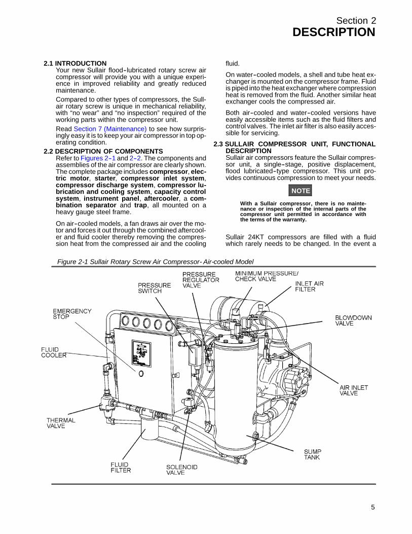
2.2 DESCRIPTION OF COMPONENTSRefer t o F igur es 2 -- 1 and 2 -- 2. T he c omponents andassemblies of the air compressor are clearly shown.The complete package includes compressor, elec-tric motor, starter, compressor inlet system,compressor discharge system, compressor lu-brication and cooling system, capacity controlsystem, instrument panel, aftercooler, a com-bination separator and trap, all mounted on aheavy gauge steel frame.
On air--cooled models, a fan draws air over the mo-tor and forces it out through the combined aftercool-er and fluid cooler thereby removing the compres-sion heat from the compressed air and the cooling
fluid.
On water--cooled models, a shell and tube heat ex-changer is mounted on the compressor frame. Fluidis piped into the heat exchanger where compressionheat is removed from the fluid. Another similar heatexchanger cools the compressed air.
Both air--cooled and water--cooled versions haveeasily accessible items such as the fluid filters andcontrol valves. The inlet air filter is also easily acces-sible for servicing.
2.3 SULLAIR COMPRESSOR UNIT, FUNCTIONALDESCRIPTIONSullair air compressors feature the Sullair compres-sor unit, a single--stage, positive displacement,flood lubricated--type compressor. This unit pro-vides continuous compression to meet your needs.
NOTE
With a Sullair compressor, there is no mainte-nance or inspection of the internal parts of thecompressor unit permitted in accordance withthe terms of the warranty.
Sullair 24KT compressors are filled with a fluidwhich rarely needs to be changed. In the event a
Figure 2-1 Sullair Rotary Screw Air Compressor- Air-cooled Model
5

Section 2DESCRIPTION
6
change of fluid is required, use only Sullair 24KTfluid.
WARNING!
Mixing of other lubricants within the compressorunit will void all warranties!
Sullair recommends that a 24KT sample be taken atthe first filter change and sent to the factory for anal-ysis. This is a free service. The sample kit with in-structions and self--addressed container is to besupplied by your Sullair dealer at start--up. The userwill receive an analysis report with recommenda-tions.
Fluid is injected into the compressor unit in largequantities and mixes directly with the air as the ro-tors turn, compressing the air. The fluid flow hasthree basic functions:1. As coolant, it controls the rise of air temperature
normally associated with the heat of compres-sion.
2. Seals the leakage paths between the rotors andthe stator and also between the rotors them-
selves.3. Acts as a lubricating film between the rotors al-
lowing one rotor to directly drive the other, whichis an idler.
After the air/fluid mixture is discharged from thecompressor unit, the fluid is separated from the air.At this time, the air flows through an aftercooler andseparator then to your service line while the fluid isbeing cooled in preparation for reinjection.
2.4 COMPRESSOR COOLING AND LUBRICATIONSYSTEM, FUNCTIONAL DESCRIPTIONRefer t o F igur es 2 -- 3A and 2 -- 3B. T he C ooling andLubrication System (air--cooled version) consists ofa fan, double shaft drive motor, radiator--type af-tercooler and fluid cooler, full flow fluid filter,thermal valve, and interconnecting piping andtubing. For water--cooled models, two shell andtube heat exchangers and a water--flow regulat-ing valve are substituted for the radiator--type cool-er listed above.
The pressure in the receiver/sump causes fluid flowby forcing the fluid from the high pressure area of thesump to an area of lower pressure in the compres-sor unit.
Figure 2-2 Sullair Rotary Screw Air Compressor- Water-cooled Model

Section 2DESCRIPTION
Figure 2-3A Compressor Fluid Cooling/Lubrication and Discharge System- Air-cooled Model
7

Section 2DESCRIPTION
Figure 2-3B Compressor Fluid Cooling/Lubrication and Discharge System- Water-cooled Model
8
Section 2DESCRIPTION
Fluid flows from the bottom of the receiver/sump tothe thermal valve. The thermal valve is fully openwhen the fluid temperature is below 170_F (77_C).The fluid passes through the thermal valve, the mainfilter and directly to the compressor unit where it lu-bricates, cools and seals the rotors and the com-pression chamber.
As the discharge temperature rises above 170_F(77_C), due to the heat of compression, the thermalvalve begins to close and a portion of the fluid thenflows through the cooler. From the cooler the fluidflows to the main filter and then on to the compres-sor unit.
A portion of the fluid flowing to the compressor isrouted to the anti--friction bearings which supportthe rotors inside the compressor unit. Prior to enter-ing the compressor unit, this fluid is taken throughthe fluid filter, thus assuring properly filtered lubri-cant for bearing supply.
The fluid filter has a replacement element and an in-tegral pressure bypass valve. A gauge on the instru-ment panel shows red when the filter needs servic-ing. This gauge has a pressure setting lower thanthat of the bypass valve. The gauge should bechecked with compressor running at full systempressure.
Water--cooled versions of the compressor have awater--flow regulating valve (not shown) which oper-ates to conserve water during periods of varyingload on the compressor. This same valve automati-cally shuts off the water supply when the compres-sor is shut down. In addition, water--cooled modelshave a water pressure switch to prevent operationwith inadequate water pressure.
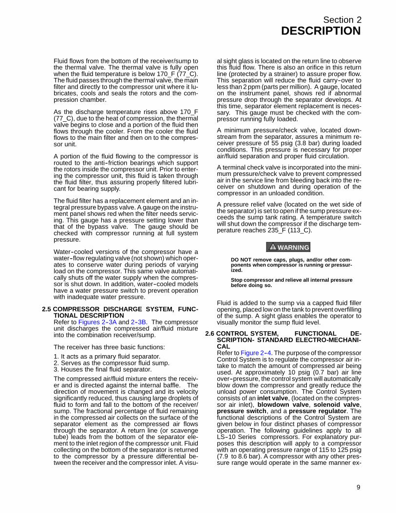
2.5 COMPRESSOR DISCHARGE SYSTEM, FUNC-TIONAL DESCRIPTIONRefer t o F igur es 2 -- 3A and 2 -- 3B. T he c ompr es s orunit discharges the compressed air/fluid mixtureinto the combination receiver/sump.
The receiver has three basic functions:1. It acts as a primary fluid separator.2. Serves as the compressor fluid sump.3. Houses the final fluid separator.The compressed air/fluid mixture enters the receiv-er and is directed against the internal baffle. Thedirection of movement is changed and its velocitysignificantly reduced, thus causing large droplets offluid to form and fall to the bottom of the receiver/sump. The fractional percentage of fluid remainingin the compressed air collects on the surface of theseparator element as the compressed air flowsthrough the separator. A return line (or scavengetube) leads from the bottom of the separator ele-ment to the inlet region of the compressor unit. Fluidcollecting on the bottom of the separator is returnedto the compressor by a pressure differential be-tween the receiver and the compressor inlet. A visu-
al sight glass is located on the return line to observethis fluid flow. There is also an orifice in this returnline (protected by a strainer) to assure proper flow.This separation will reduce the fluid carry--over toless than 2 ppm (parts per million). A gauge, locatedon the instrument panel, shows red if abnormalpressure drop through the separator develops. Atthis time, separator element replacement is neces-sary. This gauge must be checked with the com-pressor running fully loaded.
A minimum pressure/check valve, located down-stream from the separator, assures a minimum re-ceiver pressure of 55 psig (3.8 bar) during loadedconditions. This pressure is necessary for properair/fluid separation and proper fluid circulation.
A terminal check valve is incorporated into the mini-mum pressure/check valve to prevent compressedair in the service line from bleeding back into the re-ceiver on shutdown and during operation of thecompressor in an unloaded condition.
A pressure relief valve (located on the wet side ofthe separator) is set to open if the sump pressure ex-ceeds the sump tank rating. A temperature switchwill shut down the compressor if the discharge tem-perature reaches 235_F (113_C).
WARNING!
DO NOT remove caps, plugs, and/or other com-ponents when compressor is running or pressur-ized.
Stop compressor and relieve all internal pressurebefore doing so.
Fluid is added to the sump via a capped fluid filleropening, placed low on the tank to prevent overfillingof the sump. A sight glass enables the operator tovisually monitor the sump fluid level.
2.6 CONTROL SYSTEM, FUNCTIONAL DE-SCRIPTION- STANDARD ELECTRO-MECHANI-CALRefer t o F igur e 2 -- 4. T he pur pos e of t he c ompr es s orControl System is to regulate the compressor air in-take to match the amount of compressed air beingused. At approximately 10 psig (0.7 bar) air lineover--pressure, the control system will automaticallyblow down the compressor and greatly reduce theunload power consumption. The Control Systemconsists of an inlet valve, (located on the compres-sor air inlet), blowdown valve, solenoid valve,pressure switch, and a pressure regulator. Thefunctional descriptions of the Control System aregiven below in four distinct phases of compressoroperation. The following guidelines apply to allLS--10 Series compressors. For explanatory pur-poses this description will apply to a compressorwith an operating pressure range of 115 to 125 psig(7.9 to 8.6 bar). A compressor with any other pres-sure range would operate in the same manner ex-
9

Section 2DESCRIPTION
Figure 2-4 Control System
10

Section 2DESCRIPTION
cepting stated pressures.
START - 0 TO 50 PSIG (0 TO 3.5 BAR)When the compressor START button is depressed,the sump pressure will quickly rise from 0 to 50 psig(0 to 3.5 bar). During this period both the pressureregulator and the solenoid valve are closed, the inletvalve is fully open due to inlet air flow, and the com-pressor pumps at full rated capacity. The rising com-pressor air pressure is isolated from the service linein this phase by the minimum pressure valve, set atapproximately 50 psig (3.5 bar).
NORMAL OPERATING MODE - 50 TO 115 PSIG(3.5 TO 7.9 BAR )When the pressure air rises above 50 psig (3.5 bar),the minimum pressure/check valve opens and deliv-ers compressed air to the service line. From thispoint on, the line air pressure is continually moni-tored by a line pressure gauge and a pressureswitch usually set at 125 psig (8.6 bar). The pres-sure regulator and the solenoid valve remain closedduring this phase. The inlet valve remains fully openfor maximum capacity.
MODULATING MODE - 115 TO 125 PSIG (7.9 TO8.6 BAR)If less than the rated capacity of compressed air isbeing used, the service line pressure will rise above115 psig (7.9 bar). The pressure regulator valvegradually opens, applying air pressure through thecontrol line to the inlet valve piston. This causes theinlet valve to partially close reducing the amount ofair entering the compressor until it matches theamount of air being used. The control system func-tions continually in this manner, between the limitsof 115 to 125 psig (7.9 to 8.6 bar), in response tovarying demands from the service line.
The pressure regulator has an orifice which vents asmall amount of air to the atmosphere when thepressure regulator controls the inlet valve. The ori-fice also bleeds any accumulated moisture from thecontrol lines.
UNLOAD - IN EXCESS OF 125 PSIG (8.6 BAR)LINE PRESSUREWhen no air is being used,the service line pressurerises to the setting (cut--out pressure) of the pres-sure switch. the pressure switch opens, interruptingthe electrical power to the solenoid valve. At thistime, the solenoid valve allows dry sump tank airpressure or service air pressure through a shuttlevalve to be applied directly to the inlet valve pistonand keep it closed. Simultaneously, the solenoidvalve sends a pneumatic signal to the blowdownvalve. The blowdown valve opens the sump to thecompressor intake reducing the sump pressure toapproximately 25 to 27 psig (1.7to 1.9 bar). Thecheck valve in the air service line pressure preventsline pressure from returning to the sump.
When the line pressure drops to the low setting (cut--in pressure) of the pressure switch (usually 115 psig
[7.9 bar]), the pressure switch closes, re--energizingthe 3--way solenoid valve and allowing the blow-down valve to close. The re--energized solenoidvalve again prevents pressure from reaching the in-let valve. The inlet valve is fully open and the com-pressor delivers full rated capacity. Should the pres-sure begin to rise, the pressure regulator will resumeits normal function as previously described.
To accommodate varied periods of time when thereare not any air requirements, “Dual--Control” is uti-lized. This feature allows you to set the compressorin an automatic position whereby the compressorwill shut down when no compressed air requirementis present and restart as compressed air is needed.
2.7 CONTROL SYSTEM, FUNCTIONAL DE-SCRIPTION- SUPERVISOR II
Refer t o F igur e 2 -- 4. T he pur pos e of t he c ompr es s orControl System is to regulate the amount of air beingcompressed to match the amount of compressed airbeing used. The Capacity control system consists ofa solenoid valve, regulator valve and an inletvalve. The functional description of the Control Sys-tem is described below in four distinct phases of op-eration. The following description text applies to allLS--10 Series compressors with optional SupervisorII. For explanatory purposes, this description will ap-ply to a compressor with an operating range of 100to 110 psig (6.9 to 7.6 bar). A compressor with anyother pressure range would operate in the samemanner except stated pressures.START MODE - 0 TO 50 PSIG (0 TO 3.5 BAR)When the compressor “I” (START) pad is de-pressed, the sump pressure will quickly rise from 0to 50 psig (0 -- 3.4 bar). The compressor initiallystarts unloaded, then switches to full load when fullrpm has been achieved. During this period, both thepressure regulator and the solenoid valve areclosed, the inlet valve is fully open and the compres-sor pumps at full rated capacity. The rising compres-sor air pressure is isolated from the service line inthis phase by the minimum pressure valve set atapproximately 50 psig (3.4 bar).FULL LOAD MODE - 50 TO 100 PSIG (3.4 TO 6.9BAR)When the compressed air pressure rises above 50psig (3.4 bar), the minimum pressure valve opensallowing compressed air to flow into the service line.From this point on, the line air pressure is continuallymonitored by the Supervisor. The pressure regula-tor and the solenoid valve remain closed during thisphase. The inlet valve is in the fully open position aslong as the compressor is running at 100 psig ( 6.9bar) or below.MODULATING MODE -- 100 TO 110 PSIG (6.9 TO7.6 BAR)If less than the rated capacity of compressed air isbeing used, the service line pressure will rise above100 psig (6.9 bar). The pressure regulator valvegradually opens, directing air pressure to the inlet
11

Section 2DESCRIPTION
12
control valve, reducing air entering the compressoruntil it matches the amount of air being used. Thecontrol system functions continually in this mannerbetween the limits of 100 to 110 psig (6.9 to 7.6 bar)in response to varying demands from the serviceline.
The pressure regulator has an orifice which vents asmall amount of air to the atmosphere when thepressure regulator controls the inlet control valve.The orifice also bleeds any accumulated moisturefrom the pressure regulator.UNLOAD MODE - IN EXCESS OF 110 PSIG (7.6BAR)When a relatively small amount or no air is beingused, the service line pressure continues to rise.When it exceeds 110 psig (7.6 bar), the SupervisorControl System de--energizes the solenoid valve al-lowing sump air pressure to be supplied directly toclose the inlet valve. Simultaneously, the solenoidvalve sends a pneumatic signal to the blowdownvalve. The blowdown valve opens to the atmo-sphere, reducing the sump pressure to approxi-mately 25 to 27 psig (1.7 to 1.9 bar). The check valvein the air service line prevents line pressure from re-turning to the sump.When the line pressure drops to the low setting (cut--in pressure; usually 100 psig [6.9 bar] on low pres-sure [“L”] compressors and 115 psig [8.0 bar] onhigh pressure [“H”] compressors, 140 psig [9.7 bar]on [“HH”] compressors, 175 psig [12.0 bar] [“XH”] .Supervisor energizes the solenoid valve and allowsthe blowdown valve to close. The re--energized so-lenoid valve again prevents line pressure fromreaching the inlet control valve. Should the pressurebegin to rise, the pressure regulator will resume itsnormal function as previously described.AUTOMATIC OPERATIONFor applications with varied periods of time whenthere are no air requirements, Supervisor’s AUTO-MATIC mode allows the compressor to shutdown(time delayed) when no compressed air require-ment is present and restart as compressed air isneeded.
2.8 AIR INLET SYSTEM, FUNCTIONAL DE-SCRIPTIONRefer t o F igur e 2 -- 5. T he C ompr es s or I nlet Sy s t emconsists of a dry--type air filter, a restrictiongauge and an air inlet valve.
The restriction gauge (located on the instrumentpanel), indicates the condition of the air filter byshowing red when filter maintenance is required.
The poppet--type modulating air inlet valve directlycontrols the amount of air intake to the compressorin response to the operation of the pressure regula-tor ( s ee Modulating Mode, Sec t ion 2.6 [Standar dElec tor / Mec hanic al] or Sec t ion 2.7 [O ptional Su-pervisor Il]). The inlet valve also acts as a checkvalve, thus preventing reverse rotation when the
compressor is shut down.
WARNING!
“The Plastic Pipe Institute recommends against theuse of thermoplastic pipe to transport compressedair or other compressed gases in exposed aboveground locations, e.g. in exposed plant piping.” (I)
Sullube should not be used with PVC piping sys-tems. It may affect the bond at cemented joints. Cer-tain other plastic materials may also be affected.
(I) Plastic Pipe Institute, Recommendation B,Adopted January 19, 1972.
2.9 INSTRUMENT PANEL GROUP, FUNCTIONALDESCRIPTION- STANDARD ELECTRO-ME-CHANICAL CONTROLLERThe electro-mechanical controller responds to sig-nals from traditional pressure switch sensors andprovides stop/start, common fault indication ,sensor bypass timing, wye--delta transition tim-ing, and facilitates selectable automatic restart af-ter power failure. Two--wire remote Stop/Start inputis provided.Refer t o F igur e 2 -- 6 f or s pec ific loc ation of par ts de-scribed.S The sump pressure gauge continually monitorsthe sump pressure at the various load and/or unloadconditions.S The discharge temperature gauge monitors thetemperature of the air leaving the compressor unit.For both air--cooled and water--cooled compressorsthe normal reading is approximately 180_F to 205_F(82_C to 96_C).S The separator maintenance gauge monitorscondition of the separator element and shows in the
Figure 2-5 Air Inlet System

Section 2DESCRIPTION
red zone when the element restriction is excessive.S The fluid filter maintenance gauge monitors thecondition of the bearing lube filter element andshows in the red zone when the element should bechanged.S The START (I) pad turns the compressor on.S The STOP (O) pad turns the compressor off.S The hourmeter records accumulative hours of op-eration for the compressor and is useful for planning
and logging service operations.
S The POWER ON ( ) LED on the instrumentpanel indicates when power to the compressor issupplied.
S The ON LED indicates when the compressor isrunning.
S The AUTO ( ) pad is used to enable automaticcontrol.
13

Section 2DESCRIPTION
Figure 2--6 Instrument Panel Group and Controller Panel (Electro-Mechanical)
14
Section 3SPECIFICATIONS
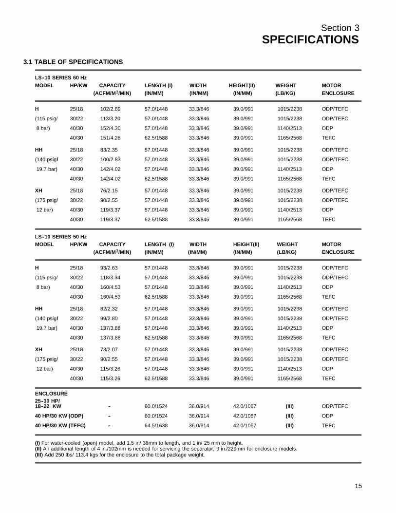
3.1 TABLE OF SPECIFICATIONS
LS--10 SERIES 60 HzMODEL HP/KW CAPACITY LENGTH (I) WIDTH HEIGHT(II) WEIGHT MOTOR
(ACFM/M3/MIN) (IN/MM) (IN/MM) (IN/MM) (LB/KG) ENCLOSURE
H 25/18 102/2.89 57.0/1448 33.3/846 39.0/991 1015/2238 ODP/TEFC
(115 psig/ 30/22 113/3.20 57.0/1448 33.3/846 39.0/991 1015/2238 ODP/TEFC
8 bar) 40/30 152/4.30 57.0/1448 33.3/846 39.0/991 1140/2513 ODP
40/30 151/4.28 62.5/1588 33.3/846 39.0/991 1165/2568 TEFC
HH 25/18 83/2.35 57.0/1448 33.3/846 39.0/991 1015/2238 ODP/TEFC
(140 psig/ 30/22 100/2.83 57.0/1448 33.3/846 39.0/991 1015/2238 ODP/TEFC
19.7 bar) 40/30 142/4.02 57.0/1448 33.3/846 39.0/991 1140/2513 ODP
40/30 142/4.02 62.5/1588 33.3/846 39.0/991 1165/2568 TEFC
XH 25/18 76/2.15 57.0/1448 33.3/846 39.0/991 1015/2238 ODP/TEFC
(175 psig/ 30/22 90/2.55 57.0/1448 33.3/846 39.0/991 1015/2238 ODP/TEFC
12 bar) 40/30 119/3.37 57.0/1448 33.3/846 39.0/991 1140/2513 ODP
40/30 119/3.37 62.5/1588 33.3/846 39.0/991 1165/2568 TEFC
LS--10 SERIES 50 HzMODEL HP/KW CAPACITY LENGTH (I) WIDTH HEIGHT(II) WEIGHT MOTOR
(ACFM/M3/MIN) (IN/MM) (IN/MM) (IN/MM) (LB/KG) ENCLOSURE
H 25/18 93/2.63 57.0/1448 33.3/846 39.0/991 1015/2238 ODP/TEFC
(115 psig/ 30/22 118/3.34 57.0/1448 33.3/846 39.0/991 1015/2238 ODP/TEFC
8 bar) 40/30 160/4.53 57.0/1448 33.3/846 39.0/991 1140/2513 ODP
40/30 160/4.53 62.5/1588 33.3/846 39.0/991 1165/2568 TEFC
HH 25/18 82/2.32 57.0/1448 33.3/846 39.0/991 1015/2238 ODP/TEFC
(140 psig/ 30/22 99/2.80 57.0/1448 33.3/846 39.0/991 1015/2238 ODP/TEFC
19.7 bar) 40/30 137/3.88 57.0/1448 33.3/846 39.0/991 1140/2513 ODP
40/30 137/3.88 62.5/1588 33.3/846 39.0/991 1165/2568 TEFC
XH 25/18 73/2.07 57.0/1448 33.3/846 39.0/991 1015/2238 ODP/TEFC
(175 psig/ 30/22 90/2.55 57.0/1448 33.3/846 39.0/991 1015/2238 ODP/TEFC
12 bar) 40/30 115/3.26 57.0/1448 33.3/846 39.0/991 1140/2513 ODP
40/30 115/3.26 62.5/1588 33.3/846 39.0/991 1165/2568 TEFC
ENCLOSURE25--30 HP/18--22 KW -- 60.0/1524 36.0/914 42.0/1067 (III) ODP/TEFC
40 HP/30 KW (ODP) -- 60.0/1524 36.0/914 42.0/1067 (III) ODP
40 HP/30 KW (TEFC) -- 64.5/1638 36.0/914 42.0/1067 (III) TEFC
(I) For water-cooled (open) model, add 1.5 in/ 38mm to length, and 1 in/ 25 mm to height.(II) An additional length of 4 in./102mm is needed for servicing the separator; 9 in./229mm for enclosure models.(III) Add 250 lbs/ 113.4 kgs for the enclosure to the total package weight.
15

Section 3SPECIFICATIONS
16
COMPRESSOR: STANDARD MODELSType: Rotary ScrewStandard Operating Pressure (IV): 100 psig (6.9bar) (L) 140 psig (9.7 bar) (HH)
115 psig (7.9bar) (H) (XH) 175 psig (12 bar) (XH)Bearing Type: Anti--FrictionAmbient Temperature (Max.) (V): 105_F (41_C)Cooling: Pressurized FluidCompressor Fluid: Sullair SullubeSump Capacity: 3.5 U.S. gallons (14.8 liters)Control: Electro--Pneumatic
Supervisor II (optional)
MOTOR (VI): STANDARD MODELSSize: 25, 30 and 40HPType: C--Flanged, Open Dripproof, Premium Efficiency
Three Phase, 230/460 60 Hz, 380/415 50 Hz40_C Maximum Ambient TemperatureOptions Available: 200V and 575VT.E.F.C. Also Available: IP54
Starter: Full Voltage Magnetic or Wye DeltaOptions Available: 200V and 575V
Speed: 60 Hz: 1770 RPM50 Hz: 1475 RPM40HP: 3000 RPM
(IV) Special compressors are available for operation at higher pressures.(V) Special compressors are available for operation in higher ambient temperature.(VI) Multi--frequency and voltage motors are used. The compressors must be used only with the specified electrical frequency and voltage.
3.2 LUBRICATION GUIDE
For best value and longest uninterrupted service,the LS--10 Series compressors are factory filledand tested with a long life lubricant.
WARNING!
Mixing of other lubricants within the compres-sor unit will void all warranties!
If, due to availability or other reasons, other fluidsar e r equir ed, follow Lubr ic ation G uide 3.4 below.
WARNING!
“The Plastic Pipe Institute recommendsagainst the use of thermoplastic pipe to trans-port compressed air or other compressedgases in exposed above ground locations, e.g.in exposed plant piping.” (I)
Sullube should not be used with PVC pipingsystems. It may affect the bond at cementedjoints. Certain other plastic materials may alsobe affected.
(I) Plastic Pipe Institute, Recommendation B,Adopted January 19, 1972.
Maintenance of all other components is still rec-ommended as indicated in the Operator’s Manu-al.
For light--duty high--humidity service where con-densed moisture and emulsification (mayon-naise) may occur, the fluid change interval mustbe reduced to 300 hours maximum. A non--deter-gent fluid with rust, oxidation and foam inhibitorsand good water separation characteristics shouldbe used.
DO NOT MIX DIFFERENT TYPES OF FLUIDS.Contamination of non--detergent mineral fluidswith traces of detergent motor fluids may lead tooperational problems such as foaming, filter plug-ging, orifice or line plugging.
NOTE
Flush system when switching lubricantbrands.
When ambient conditions exceed those noted orif conditions warrant use of “extended” life lubri-cants contact Sullair for recommendation.
3.3 APPLICATION GUIDESullair encourages the user to participate in afluid analysis program with the fluid suppliers.This could result in a fluid change interval differ-ing from that stated in the manual. Contact yourSullair dealer for details.
Section 3SPECIFICATIONS
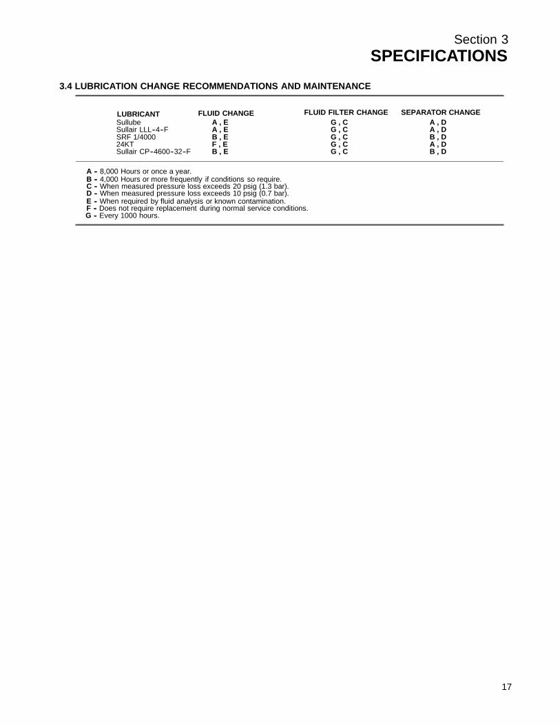
3.4 LUBRICATION CHANGE RECOMMENDATIONS AND MAINTENANCE
LUBRICANT FLUID CHANGE SEPARATOR CHANGE
B -- 4,000 Hours or more frequently if conditions so require.
FLUID FILTER CHANGE
C -- When measured pressure loss exceeds 20 psig (1.3 bar).D -- When measured pressure loss exceeds 10 psig (0.7 bar).E -- When required by fluid analysis or known contamination.F -- Does not require replacement during normal service conditions.
A -- 8,000 Hours or once a year.
G -- Every 1000 hours.
Sullube A , E G , C A , DSullair LLL--4--F A , E G , C A , DSRF 1/4000 B , E G , C B , D24KT F , E G , C A , DSullair CP--4600--32--F B , E G , C B , D
17

Section 3SPECIFICATIONS
Figure 3-1 Identification- Air-cooled Models
18

Section 3SPECIFICATIONS
Figure 3-2 Identification- Water-cooled 25-30HP/ 18-22KW Models
19

Section 3SPECIFICATIONS
Figure 3-2 Identification- Water-cooled 40HP/ 30KW Model
20

Section 4INSTALLATION
4.1 MOUNTING OF COMPRESSORA foundation or mounting capable of supporting theweight of the compressor, and rigid enough to main-tain the compressor frame level and the compressorin alignment is required. The compressor framemust be leveled and secured with foundation bolts,and full uniform contact must be maintained be-tween the frame and foundation. No piping loadsshall be transmitted to the compressor at the exter-nal connections.
4.2 VENTILATION AND COOLINGFor air--cooled compressors, select a location topermit sufficient unobstructed air flowing in and outto the compressor to keep the operating tempera-ture stable. The minimum distance that the com-pressor should be from surrounding walls is three(3) feet (1m). To prevent excessive ambient temper-ature rise, it is imperative to provide adequate ven-tilation.
For water--cooled compressors, it is necessary tocheck the cooling water supply. The water systemmus t be c apable of s upply ing the f lows s hown inTable I -- Water Supply R equir ements ( Water --cooled), and must be maintained at all times. Thesefigures apply to a compressor running at full loadwith an aftercooler. For cooler water or a partiallyloaded compressor, slightly less water is required.However, for hotter water the flow requirements aresignificantly greater.
Table 2 -- Ventilation Requir ements indic ates t heventilation requirements necessary to keep thecompressor running at a normal operating tempera-
ture. The fan air requirement is the volume of airwhich must flow through the compressor for properventilation. The specified heat rejection requirementis the amount of heat that is radiated by the com-pressor. This heat must be removed to assure a nor-mal operating temperature. With air--cooled com-pressors it is possible to use this heat for spaceheating, providing no additional pressure drop iscreated across the fan. Consult a Sullair office forassistance in utilizing this heat.
DO NOT install a water--cooled or an air--cooled/af-tercooled compressor where it will be exposed totemperatures less than 32_F(0_C).
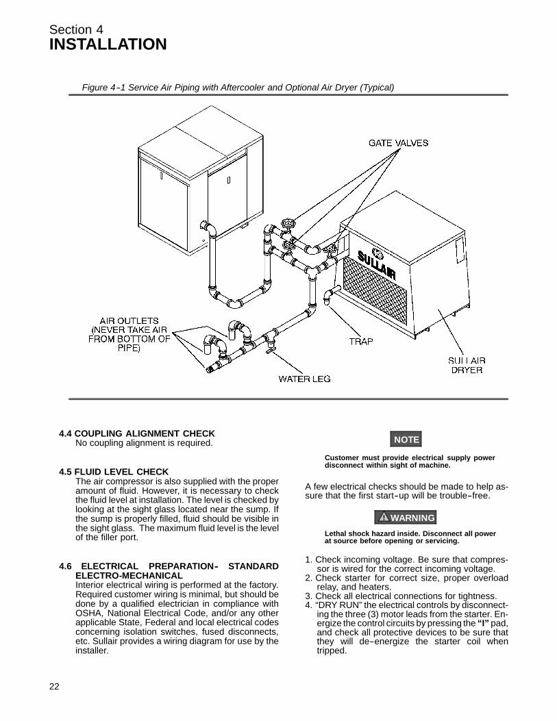
4.3 SERVICE AIR PIPINGService air piping should be installed as shown inF igur e 4 -- 1. A s hut -- off v alv e s hould be ins talled t oisolate the compressor from the service line if re-quired. Also notice that the service line should beequipped with water legs and condensate drainsthroughout the system.
WARNING!
“The Plastic Pipe Institute recommends against theuse of thermoplastic pipe to transport compressedair or other compressed gases in exposed aboveground locations, e.g. in exposed plant piping.” (I)
Sullube should not be used with PVC piping sys-tems. It may affect the bond at cemented joints. Cer-tain other plastic materials may also be affected.
(I) Plastic Pipe Institute, Recommendation B,Adopted January 19, 1972.
(I) Water pressure should be between 25 and 75 psig/ 1.7 and 5.2 bar.
TABLE 1--WATER SUPPLY REQUIREMENTS (WATER--COOLED)WATER FLOW (I)
WATER TEMP. GPM/ LPM0_F/ _C 25HP/ 18KW 30HP/ 22KW 40HP/ 30KW70/ 21 3.75/ 14.2 4.50 /17.0 5.75/ 21.8
80/ 26.6 5.00/ 18.9 6.00/ 22.7 7.50 /28.4
Cooling Type Air-cooled with Aftercooler Water-cooled
Motor HP/KW 25/18 30/22 40/30 25/18 30/22 30/40
Fan Air CFM 2500/4250 2500/4250 3500/5950 720/1220 720/1220 720/1220M3/Hr (II)
Ventilating Air/Heat RejectionBTU/Hour 76980/ 88800/ 118320/ 8500/ 10000/ 13000KCal/Hour 19500 22500 29900 2150 2550 3300Cooling Water/Heat RejectionBTU/Hour 76980/ 88800/ 118320/Kcal/Hour 19500 22500 29900
(II) Applies to compressor with canopy only (vent fan).(I) Values based on: 100% RH, 85_F/ 29_C Ambient
TABLE 2--VENTILATION REQUIREMENTS (I)
21
Section 4INSTALLATION
22
4.4 COUPLING ALIGNMENT CHECKNo coupling alignment is required.
4.5 FLUID LEVEL CHECKThe air compressor is also supplied with the properamount of fluid. However, it is necessary to checkthe fluid level at installation. The level is checked bylooking at the sight glass located near the sump. Ifthe sump is properly filled, fluid should be visible inthe sight glass. The maximum fluid level is the levelof the filler port.
4.6 ELECTRICAL PREPARATION-- STANDARDELECTRO-MECHANICALInterior electrical wiring is performed at the factory.Required customer wiring is minimal, but should bedone by a qualified electrician in compliance withOSHA, National Electrical Code, and/or any otherapplicable State, Federal and local electrical codesconcerning isolation switches, fused disconnects,etc. Sullair provides a wiring diagram for use by theinstaller.
NOTE
Customer must provide electrical supply powerdisconnect within sight of machine.
A few electrical checks should be made to help as-sure that the first start--up will be trouble--free.
WARNING!
Lethal shock hazard inside. Disconnect all powerat source before opening or servicing.
1. Check incoming voltage. Be sure that compres-sor is wired for the correct incoming voltage.
2. Check starter for correct size, proper overloadrelay, and heaters.
3. Check all electrical connections for tightness.4. “DRY RUN” the electrical controls by disconnect-
ing the three (3) motor leads from the starter. En-ergize the control circuits by pressing the “I” pad,and check all protective devices to be sure thatthey will de--energize the starter coil whentripped.
Figure 4--1 Service Air Piping with Aftercooler and Optional Air Dryer (Typical)
Section 4INSTALLATION
5. Reconnect the motor leads and jog the motor fora dir ec tion of r otation c hec k as ex plained in Sec -tion 4.8.
NOTE
Wiring diagram for standard compressors is sup-plied on the inside cover of the Control Center.Optional compressor wiring diagrams will vary.
4.7 ELECTRICAL PREPARATION-- SUPERVISOR IIInterior electrical wiring is performed at the factory.Required customer wiring is minimal, but should bedone by a qualified electrician in compliance withOSHA, National Electric Code and/or any applica-ble local electrical code concerning isolationswitches, fused disconnects, etc. Sullair provides awiring diagram for use by the installer.
An electrical check should be made to help assurethat the first start--up will be trouble--free.
DANGER!
Lethal shock hazard inside. Disconnect all powerat source, before opening or servicing.
1. Check incoming voltage. Be sure that the incom-ing voltage is the same voltage that the compres-sor was wired for.
2. Check starter and overload heater sizes.3. Check all electrical connections for tightness.4. “DRY RUN” the electrical controls by disconnect-
ing the three (3) motor leads from the starter. En-ergize the control circuits by pushing the “I”(START) pad and check all protective devices to
be sure that they will de--energize the starter coilwhen tripped.
5. Reconnect the three (3) motor leads and jog themotor for a direction of rotation check, as ex-plained in Sec t ion 4 .9.
4.8 MOTOR ROTATION DIRECTION CHECK
NOTE
Motor rotation check must be made at compressorstart--up. Remove compressor panel as needed toview motor rotation.
After the electrical wiring has been done, it is neces-sary to check the direction of the motor rotation.Pull out the EMERGENCY STOP button and pressonce, quickly and in succession, the “I” (START)and “O” (STOP) pads. This action will bump startthe motor for a very short time. When looking at themotor from the end opposite the compressor unit,the shaft should be turning clockwise. If the re-versed rotation is noted, disconnect the power to thestarter and exchange any two of the three power in-put leads, then re--check rotation. A “Direction ofRotation” decal is located on the motor to showproper motor/compressor rotation.An alternative to this procedure is to set the Supervi-sor to display P1. Pull out the EMERGENCY STOPbutton and press once, quickly and in succession,the “I” (START) and “O” (STOP) pads. This actionwill bump start the motor for a very short time. If mo-tor rotation is correct there will be immediate pres-sure shown. If no pressure is present, reverse rota-tion is occurring. Disconnect the power to the starterand exchange any two of the three power inputleads. Recheck rotation as outlined above.
23

24
NOTES
Section 5OPERATION- ELECTRO-MECHANICAL
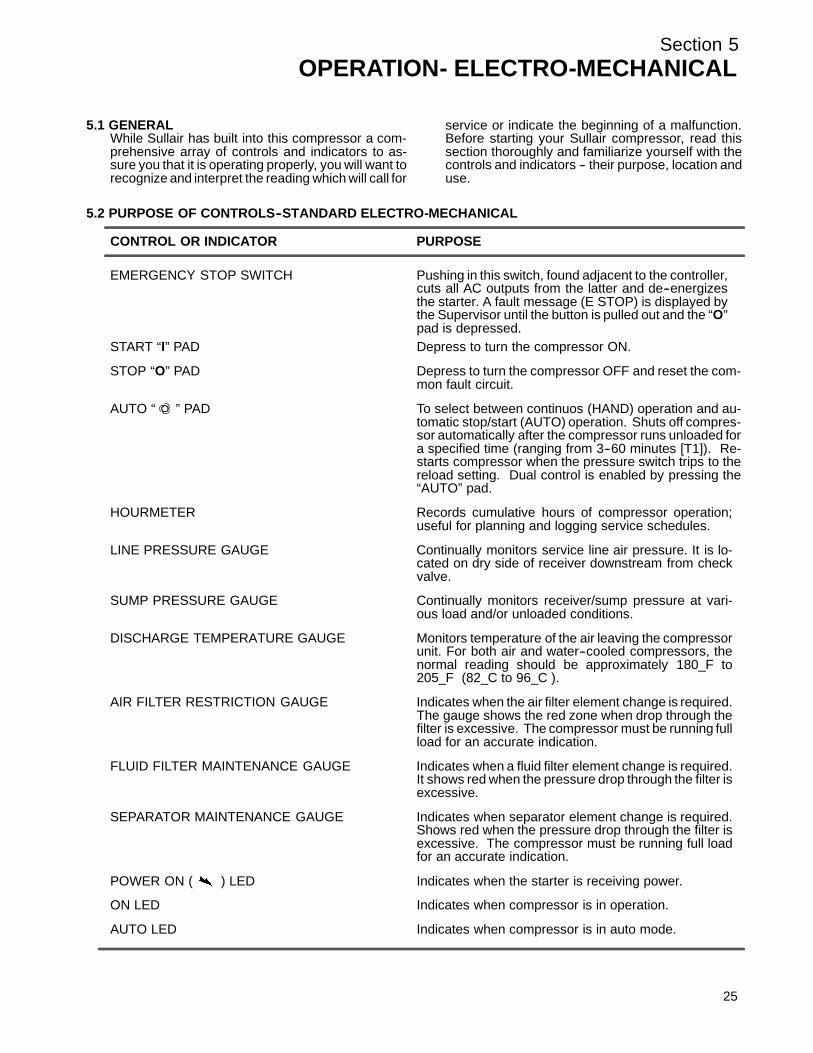
5.1 GENERALWhile Sullair has built into this compressor a com-prehensive array of controls and indicators to as-sure you that it is operating properly, you will want torecognize and interpret the reading which will call for
service or indicate the beginning of a malfunction.Before starting your Sullair compressor, read thissection thoroughly and familiarize yourself with thecontrols and indicators -- their purpose, location anduse.
5.2 PURPOSE OF CONTROLS--STANDARD ELECTRO-MECHANICAL
CONTROL OR INDICATOR PURPOSE
EMERGENCY STOP SWITCH Pushing in this switch, found adjacent to the controller,cuts all AC outputs from the latter and de--energizesthe starter. A fault message (E STOP) is displayed bythe Supervisor until the button is pulled out and the “O”pad is depressed.
START “I” PAD Depress to turn the compressor ON.
STOP “O” PAD Depress to turn the compressor OFF and reset the com-mon fault circuit.
AUTO “ ” PAD To select between continuos (HAND) operation and au-tomatic stop/start (AUTO) operation. Shuts off compres-sor automatically after the compressor runs unloaded fora specified time (ranging from 3--60 minutes [T1]). Re-starts compressor when the pressure switch trips to thereload setting. Dual control is enabled by pressing the“AUTO” pad.
HOURMETER Records cumulative hours of compressor operation;useful for planning and logging service schedules.
LINE PRESSURE GAUGE Continually monitors service line air pressure. It is lo-cated on dry side of receiver downstream from checkvalve.
SUMP PRESSURE GAUGE Continually monitors receiver/sump pressure at vari-ous load and/or unloaded conditions.
DISCHARGE TEMPERATURE GAUGE Monitors temperature of the air leaving the compressorunit. For both air and water--cooled compressors, thenormal reading should be approximately 180_F to205_F (82_C to 96_C ).
AIR FILTER RESTRICTION GAUGE Indicates when the air filter element change is required.The gauge shows the red zone when drop through thefilter is excessive. The compressor must be running fullload for an accurate indication.
FLUID FILTER MAINTENANCE GAUGE Indicates when a fluid filter element change is required.It shows red when the pressure drop through the filter isexcessive.
SEPARATOR MAINTENANCE GAUGE Indicates when separator element change is required.Shows red when the pressure drop through the filter isexcessive. The compressor must be running full loadfor an accurate indication.
POWER ON ( ) LED Indicates when the starter is receiving power.
ON LED Indicates when compressor is in operation.
AUTO LED Indicates when compressor is in auto mode.
25

Section 5OPERATION- ELECTRO-MECHANICAL
5.2 PURPOSE OF CONTROLS--STANDARD ELECTRO-MECHANICAL (CONTINUED)
CONTROL OR INDICATOR PURPOSE
FLUID LEVEL SIGHT GLASS Monitors fluid level in the sump. The fluid must be vis-ible in the glass. Check the level when the compressoris shut down. Maximum fill level is the level of the fillport, minimizing the risk of overfilling.
SEPARATOR RETURN LINE SIGHT GLASS Used to indicate fluid flow in the return line. When thecompressor is running at full load, fluid flow should bevisible in this sight glass. There may be little or no flowwhen the compressor is running unloaded, but a slug-gish flow at full load indicates a need to clean the returnline strainer.
THERMAL VALVE Regulates flow of fluid to and around the cooler. It is de-signed to maintain a minimum operating temperature of180_F (82_C); use for fast warm--up on start--up.
MINIMUM PRESSURE/CHECK VALVE Maintains minimum of 55 psig (3.8 bar) in the compres-sor sump. Valve piston restricts receiver air dischargefrom receiver/sump when pressure falls to 55 psig (3.8bar). Also prevents backflow into the sump during un-load conditions and after shutdown.
COMPRESSOR DISCHARGE Designed to shut the compressor down when theTEMPERATURE SWITCH discharge temperature reaches 235_F (113_C).
WATER PRESSURE SWITCH It prevents operation when water pressure of(water--cooled compressors only) compressor is inadequate.
PRESSURE RELIEF VALVE Opens sump pressure to the atmosphere should pres-sure inside the sump become too high. Operation of thisvalve indicates that the high pressure switch is eitherfaulty or out of adjustment.
MODULATING INLET VALVE Regulates the amount of air allowed to enter the aircompressor. This regulation is determined by theamount of air being used at the service line. Also acts asa check valve to prevent reverse compressor rotation atshut down.
PRESSURE REGULATOR Allows a pressure signal to reach the air inlet valve tocontrol air delivery according to demand.
SOLENOID VALVE Bypasses the pressure regulator valve causing the inletvalve to close when the compressor reaches maximumoperating pressure. Also activates blow--down valve.
PRESSURE SWITCH Senses service line pressure. When line pressurereaches maximum setting the pressure switch signalsthe pilot valves to unload the compressor.
BLOWDOWN VALVE Vents sump pressure to the atmosphere during unloadconditions and shutdown.
WATER REGULATING VALVE Regulates the amount of cooling water used to keep(water--cooled only) the compressor running at a normal operating temp--
erature.
T1 (AUTOMATIC STOP TIMER) Adjustable from three (3) to 60 minutes. Located onrear of the controller.
26
Section 5OPERATION- ELECTRO-MECHANICAL
5.2 PURPOSE OF CONTROLS--STANDARD ELECTRO-MECHANICAL (CONTINUED)
CONTROL OR INDICATOR PURPOSE
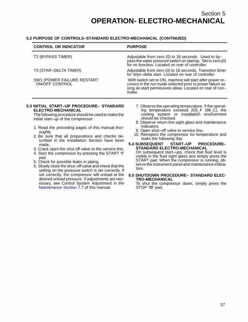
T2 (BYPASS TIMER) Adjustable from zero (0) to 16 seconds. Used to by--pass the water pressure switch on startup. Set to zero (0)for no function. Located on rear of controller.
T3 (STAR--DELTA TIMER) Adjustable from zero (0) to 16 seconds. Transition timerfor Wye--delta start. Located on rear of controller.
SW1 (POWER FAILURE RESTART With switch set to ON, machine will start after power re--ON/OFF CONTROL covery in the run mode selected prior to power failure as
long as start permissives allow. Located on rear of con--troller.
5.3 INITIAL START--UP PROCEDURE-- STANDARDELECTRO-MECHANICALThe following procedure should be used to make theinitial start--up of the compressor:
1. Read the preceding pages of this manual thor-oughly.
2. Be sure that all preparations and checks de-scribed in the Installation Section have beenmade.
3. Crack open the shut off valve to the service line.4. Start the compressor by pressing the START “I”
pad.5. Check for possible leaks in piping.6. Slowly close the shut--off valve and check that the
setting on the pressure switch is set correctly. Ifset correctly, the compressor will unload at thedesired unload pressure. If adjustments are nec-essary, see Control System Adjustment in theMaintenanc e Sec tion 7.7 of t his manual.
7. Observe the operating temperature. If the operat-ing temperature exceeds 205_F (96_C), thecooling system or installation environmentshould be checked.
8. Observe return line sight glass and maintenanceindicators.
9. Open shut--off valve to service line.10. Reinspect the compressor for temperature and
leaks the following day.
5.4 SUBSEQUENT START--UP PROCEDURE--STANDARD ELECTRO-MECHANICALOn subsequent start--ups, check that fluid level isvisible in the fluid sight glass and simply press theSTART pad. When the compressor is running, ob-serve the instrument panel and maintenance indica-tors.
5.5 SHUTDOWN PROCEDURE-- STANDARD ELEC-TRO-MECHANICALTo shut the compressor down, simply press theSTOP “O” pad.
27

Section 6OPERATION- SUPERVISOR II
Figure 6-1 Supervisor II Panel
28

Section 6OPERATION- SUPERVISOR II
6.1 INTRODUCTIONRefer t o F igur e 6 -- 1 f or infor mation r egar ding y ourcompressor with Supervisor II. The Supervisor IIhas a two line display to show temperature, pres-sure and status. It has a keypad for operating thecompressor, programming the control points andselecting displays. There is a graphic illustrationwith lamps that light to show the item being dis-played. The lamps flash if that component is in analarm condition.
6.2 KEYPADThe keypad is used to control the machine as well asdisplay status and change setpoints. Refer to figure6--1 for following key descriptions.
S Stop -- Used to put the machine into manu-al stop. It is also used to clear alarm condi-tions.
OS Continuous -- Starts machine if no alarmconditions are present. Also used to clearalarm conditions while machine is running.
IS Auto -- Starts machine and selects automode if no alarm conditions are present.Also used to clear alarm conditions whilemachine is running.
S Display -- Used to display pressures, tem-peratures and other status information (Seesection on STATUS DISPLAYS).
DSP
S Logo -- Used for various functions de-scribed in later sections.
S Program -- Used to enter the parameterchange mode where control parametersmay be displayed and changed (See PA-RAMETER SETUP).
PRG
S Up arrow -- Used in status displays tochange displays and in parameter setupmode to increment a value.
S Down arrow, lamp test -- Used in statusdisplays to change displays and in parame-ter setup mode to increment a value. Whenin the default display the key will light all thelamps for three seconds.
6.3 STATUS DISPLAYSBy default the line pressure (P2) and discharge tem-perature (T1) are shown on the bottom line of thedisplay, and machine status on the top line.The following are the various machine status mes-sages that indicate the state of the compressor withLCD graphics listed below:
S STOP -- Compressor is off.
S STANDBY -- Compressor is off but armedto start. This state may be entered becauseof a power up, or the unload timer had ex-pired and stopped the machine. NOTE :The machine may start at any time.
S STARTING -- Machine is trying to start.
S OFF LOAD -- Machine is running and offloaded.
S ON LOAD -- Machine is running andloaded.
S FULL LD -- Machine is running and fullyloaded. This state is only displayed if themachine has a full load valve and under se-quence control.
S RMT STOP -- Compressor is off but armedto start. The machine will start when the re-mote start contact is closed. NOTE : themachine may start at any time.
S SEQ STOP -- Compressor is off but armedto start. The machine will start when the se-quencing conditions meet the criteria tostart. NOTE : the machine may start at anytime.
This default display appears as follows:
If there are alarms active they will alternately beshown with the default display. The machine statuswill be displayed for two seconds, then the alarms
29

Section 6OPERATION- SUPERVISOR II
30
STOP110 180
for two seconds each. For example:
T1 HI110 180
To view other status press the DSP key. All tempera-tures and pressures may be displayed as well asother status information. To scroll through the dis-plays press the up arrow or down arrow keys. Up ar-row moves to the next display, down arrow the pre-vious display. To return to the default display pressthe display key.
S Separator differential pressure and themaximum limit. If the limit is exceeded, aseparator maintenance warning will be dis-played.
nMAX 10
P1 4
S Sump pressure and line pressure.
P1 113P2 108
S Pressure after (P3) oil filter.
P3 108
S Oil differential pressure and the minimumlimit. If the pressure goes below the limit aP3 LOW shutdown will occur. Oil differential(dP3) is defined as P3--P1/2
dP3 40MIN 1
S Unit discharge temperature and the maxi-mum limit. If the temperature exceeds thelimit a T1 HI shutdown will occur.
T1 210MAX 235
S Total hours that the compressor has beenrunning.
HRS RUN001234.0
S Total hours that the compressor has beenloaded.
HRS LOAD000987.0
S Last fault log. This shows the fault on thefirst line and the run hours when the fault oc-curred.
T1 HI@1 234
S Next to last fault log. This shows the faulton the first line and the run hours when thefault occurred.
T1 HI@2 204
6.4 LAMP INDICATORSEmbedded into the front panel schematic of thecompressor are several lamps. Pressing the lamptest key will light all the lamps for three seconds.Each LED lamp has the following purpose.
P1 -- If lit steady, signifies that P1 is being displayed;if flashing denotes the presence of an alarm.
P2 -- If lit steady, signifies that P2 is being displayed;if flashing denotes the presence of an alarm.
ΔP1 -- If lit steady, signifies that ΔP1 is being dis-played; if flashing denotes replacement of separatoris needed.
ΔP2 -- If lit, indicates replacement of fluid filter isneeded.
T1 -- If lit steady, signifies that T1 is being displayed;if flashing denotes the presence of an alarm.
INLET FILTER -- Same as ΔP2.
MOTOR -- If flashing, indicates the motor overloadcontact has opened.
POWER ON -- Lit if 120VAC power is applied to theSupervisor II.
ON -- If lit steady, the compressor is running. If flash-ing, indicates that the compressor is armed butstopped because of restart timer not expired, re-mote stop or sequence stop. The compressor maystart at any time.
AUTO -- If lit steady, the compressor is running andin auto mode. If flashing, indicates that the compres-sor is armed but stopped because of restart timernot expired, remote stop or sequence stop. Thecompressor may start at any time.

Section 6OPERATION- SUPERVISOR II
6.5 OPERATION INTRODUCTIONWhile Sullair has built into this compressor a com-prehensive array of controls and indicators to as-sure you that it is operating properly, you will want torecognize and interpret the readings which will callfor service or indicate the beginning of a malfunc-tion. Before starting your Sullair compressor, readthis section thoroughly and familiarize yourself withthe controls and indicators -- their purpose, locationand use.
6.6 SUPERVISOR II PARAMETER SETUPPressing the program key enters parameter displayand edit mode. To move to the next parameter pressthe program key. To increment a parameter pressthe up arrow key or logo key. The logo key will incre-ment by 10. To decrement the value press the downarrow key.The parameters are displayed in the following order:
S Unload pressure -- The pressure wherethe machine is unloaded. For example ifthis parameter is set to 110 psi (7.6 bar) themachine will unload when the line pressureis above 110 psi (7.6 bar).
UNLOAD100 PSI
S Load differential -- The pressure differen-tial below the unload pressure where themachine is loaded. For example, if the un-load pressure is set to 110 psi (7.6 bar) andthe load differential is set to 10 psi (0.7 bar),the machine will load when the line pres-sure goes below 100 psi (6.9 bar).
LOAD10 PSI
S P1 Max -- Maximum sump pressure. Analarm and shut down will occur when thesump pressure rises above this pressure.
P1 MAX135 PSI
S Wye to delta transition timer -- For fullvoltage starters this parameter is set to 0.
WYE DELT10 SEC
S Restart time -- Time to wait after power upbefore starting machine. This parameter isused to keep several machines from start-ing at the same time after power up, or todelay start until other equipment is started.
If disabled the machine will not automatical-ly start after power up.
RST TIME10 SEC
S Unload Stop Timer -- If the machine is run-ning in AUTO mode, this parameter speci-fies the amount of time that the machine willrun unloaded before shutting off. If the timeis set less than 15 minutes (for example fiveminutes), there may be times when the ma-chine will run unloaded for more than fiveminutes. This is because there is anothertimer that keeps the machine from beingstarted more than four times an hour.
UNLD TIM15 MIN
S Language select -- English, German,Spanish, Italian and French may be se-lected for display language.
LANGUAGEENGLISH
S Units -- English or metric units may be se-lected.
UNITSENGLISH
S Communications ID # -- This is the net-work address of a machine. If there is morethan one machine connected to the net-work, each machine must have a uniquenumber.
COM ID #1
S Communications baud rate -- Thisshould always be selected to 9600 baud forall sequencing modes. It may be lower forslave or monitoring modes.
BAUDRATE9600
S Sequence method -- This parameter setsthe method used for optional sequencing.The choices are DISABLED, REMOTE,SLAVE, HOURS, COM ID#. See the Se-quencing & Protocol Manual (See Recom-mended Spare Parts List) for details about
31

Section 6OPERATION- SUPERVISOR II
32
these modes.
SEQUENCEHOURS
S Drain interval -- The time between actua-tion of the drain valve.
DRN INTV10 MIN
S Drain time -- The amount of time that thedrain valve is actuated.
DRN TIM1 SEC
S Last Communication Number -- Usedonly for sequencing, see Sequencing &Protocol Manual for details.
LAST COM3
S Lowest Allowable Pressure -- Used onlyfor sequencing, see Sequencing & ProtocolManual for details.
LOWEST90 PSI
S Recovery Time -- Used only for sequenc-ing, see Sequencing & Protocol Manual fordetails.
RECOVER10 SEC
S Rotate Time -- Used only for sequencing --units in HOURS, see Sequencing & Proto-col Manual for details.
ROTATE50 HOURS
S Machine Capacity -- Used only for se-quencing -- units in CFM (M3/min), see Se-quencing & Protocol Manual for details.
CAPACITY100
S Sequence Hours -- Used only for se-quencing, see Sequencing & Protocol
Manual for details.
SEQ HRS1000
6.7 OPERATING THE COMPRESSORBefore operating the compressor the operating pa-rameters must be setup. See the previous sectionon operating parameter setup.
MANUAL OPERATION MODEIn this mode the compressor will run indefinitely, aslong as temperatures and pressure remain withinthe valid operating ranges, and the motor overloador emergency stop contacts are not tripped. Press-ing the “I” will turn on the compressor and put it inmanual mode. If the compressor is already running,but in automatic mode, pressing “I” will switch op-eration to manual. Pressing “I” while already runningin manual mode will cause the Supervisor to turn offthe common fault relay, if engaged, and clear anymaintenance indicators.To stop the compressor, press “O” If the compres-sor is already off when “O” is pressed, the commonfault relay will be turned off, if engaged, and it will tryto clear the alarm and maintenance indicators. Re-gardless of what the compressor is doing, pressing“O” puts the Supervisor in manual stop mode.AUTOMATIC OPERATION MODEIn this mode the compressor will start if line pressure(P2) is less than the LOAD parameter. It will stop ifthe compressor runs unloaded for the number ofminutes indicated by the UNLD TIM parameter. Toput the compressor in automatic mode press “ ”. IfP2 is already less than LOAD the compressor willstart immediately, otherwise the system status willindicate STANDBY and the LED marked AUTO willflash.
If the compressor is already running, but in continu-ous mode, pressing “ ” will switch operation to au-tomatic. Pressing “ ” while already running in auto-matic mode will cause the Supervisor to turn off thecommon fault relay, if engaged, and clear any main-tenance indicators.In automatic mode the compressor can be stoppedmanually by pressing “O”. Stopping the compressorusing “O” will put the Supervisor in manual stopmode.Regardless of whether in “automatic” or “manual”mode, control of the load solenoid will be based onthe parameters UNLD and LOAD. This operation isas follows:
P2 > UNLD ----> load solenoid turned offP2 < LOAD ----> load solenoid turned on
POWER FAILURE RESTARTIf the restart timer (RST TIME parameter) is dis-
Section 6OPERATION- SUPERVISOR II
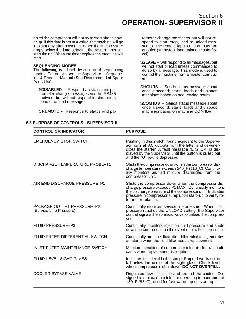
abled the compressor will not try to start after a pow-er up. If this time is set to a value, the machine will gointo standby after power up. When the line pressuredrops below the load setpoint, the restart timer willstart timing. When the timer expires the machine willstart.
SEQUENCING MODESThe following is a brief description of sequencingmodes. For details see the Supervisor II Sequenc-ing & Protocol Manual (See Recommended SpareParts List).
S DISABLED -- Responds to status and pa-rameter change messages via the RS485network but will not respond to start, stop,load or unload messages.
S REMOTE -- Responds to status and pa-
rameter change messages but will not re-spond to start, stop, load or unload mes-sages. The remote inputs and outputs areenabled (start/stop, load/unload, master/lo-cal).
S SLAVE -- Will respond to all messages, butwill not start or load unless commanded todo so by a message. This mode is used tocontrol the machine from a master comput-er.
S HOURS -- Sends status message aboutonce a second; starts, loads and unloadsmachines based on sequencing hours.
S COM ID # -- Sends status message aboutonce a second; starts, loads and unloadsmachines based on machine COM ID#.
6.8 PURPOSE OF CONTROLS - SUPERVISOR II
CONTROL OR INDICATOR PURPOSE
EMERGENCY STOP SWITCH Pushing in this switch, found adjacent to the Supervi-sor, cuts all AC outputs from the latter and de--ener-gizes the starter. A fault message (E STOP) is dis-played by the Supervisor until the button is pulled outand the “O” pad is depressed.
DISCHARGE TEMPERATURE PROBE--T1 Shuts the compressor down when the compressor dis-charge temperature exceeds 240_F (116_C). Continu-ally monitors air/fluid mixture discharged from thecompressor unit.
AIR END DISCHARGE PRESSURE--P1 Shuts the compressor down when the compressor dis-charge pressure exceeds P1 MAX. Continually monitorsthe discharge pressure of the compressor unit. Indicatespressure in compressor sump upon start--up to verify ro-tor motor rotation.
PACKAGE OUTLET PRESSURE--P2 Continually monitors service line pressure. When line(Service Line Pressure) pressure reaches the UNLOAD setting, the Supervisor
control signals the solenoid valve to unload the compres-sor.
FLUID PRESSURE--P3 Continually monitors injection fluid pressure and shutsdown the compressor in the event of low fluid pressure.
FLUID FILTER DIFFERENTIAL SWITCH Continually monitors fluid filter differential and generatesan alarm when the fluid filter needs replacement.
INLET FILTER MAINTENANCE SWITCH Monitors condition of compressor inlet air filter and indi-cates when replacement is required.
FLUID LEVEL SIGHT GLASS Indicates fluid level in the sump. Proper level is not tofall below the center of the sight glass. Check levelwhen compressor is shut down. DO NOT OVERFILL.
COOLER BYPASS VALVE Regulates flow of fluid to and around the cooler. De-signed to maintain a minimum operating temperature of180_F (82_C); used for fast warm--up on start--up.
33
Section 6OPERATION- SUPERVISOR II
3
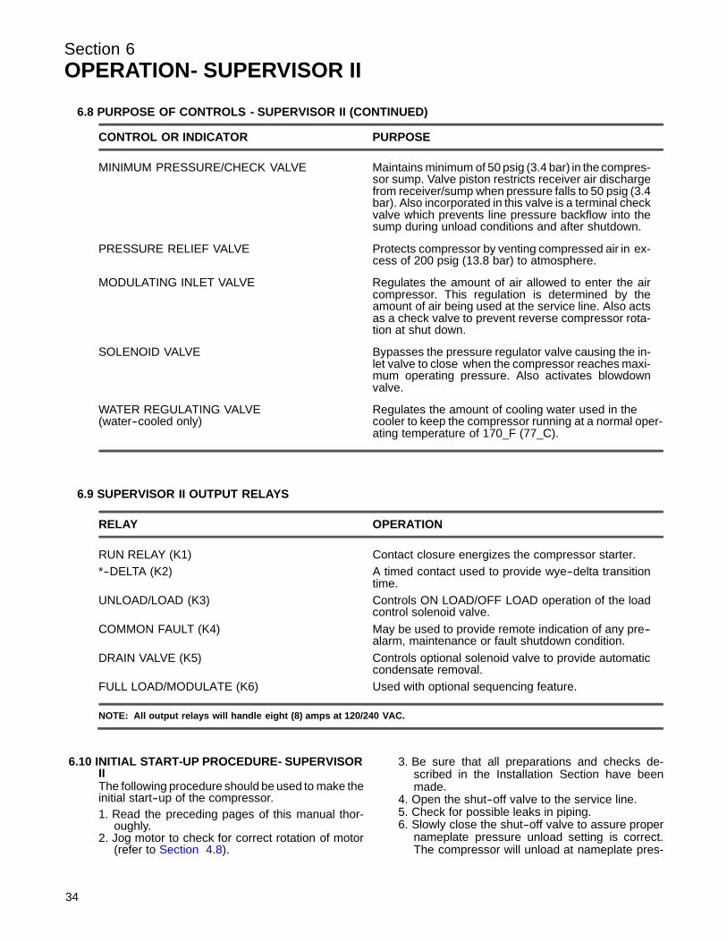
6.8 PURPOSE OF CONTROLS - SUPERVISOR II (CONTINUED)
CONTROL OR INDICATOR PURPOSE
MINIMUM PRESSURE/CHECK VALVE Maintains minimum of 50 psig (3.4 bar) in the compres-sor sump. Valve piston restricts receiver air dischargefrom receiver/sump when pressure falls to 50 psig (3.4bar). Also incorporated in this valve is a terminal checkvalve which prevents line pressure backflow into thesump during unload conditions and after shutdown.
PRESSURE RELIEF VALVE Protects compressor by venting compressed air in ex-cess of 200 psig (13.8 bar) to atmosphere.
MODULATING INLET VALVE Regulates the amount of air allowed to enter the aircompressor. This regulation is determined by theamount of air being used at the service line. Also actsas a check valve to prevent reverse compressor rota-tion at shut down.
SOLENOID VALVE Bypasses the pressure regulator valve causing the in-let valve to close when the compressor reaches maxi-mum operating pressure. Also activates blowdownvalve.
WATER REGULATING VALVE Regulates the amount of cooling water used in the(water--cooled only) cooler to keep the compressor running at a normal oper-
ating temperature of 170_F (77_C).
6.9 SUPERVISOR II OUTPUT RELAYS
RELAY OPERATION
RUN RELAY (K1) Contact closure energizes the compressor starter.*--DELTA (K2) A timed contact used to provide wye--delta transition
time.UNLOAD/LOAD (K3) Controls ON LOAD/OFF LOAD operation of the load
control solenoid valve.COMMON FAULT (K4) May be used to provide remote indication of any pre--
alarm, maintenance or fault shutdown condition.DRAIN VALVE (K5) Controls optional solenoid valve to provide automatic
condensate removal.FULL LOAD/MODULATE (K6) Used with optional sequencing feature.
NOTE: All output relays will handle eight (8) amps at 120/240 VAC.
6.10 INITIAL START-UP PROCEDURE- SUPERVISORIIThe following procedure should be used to make theinitial start--up of the compressor.1. Read the preceding pages of this manual thor-
oughly.2. Jog motor to check for correct rotation of motor
( r efer t o Sec tion 4.8) .
4
3. Be sure that all preparations and checks de-scribed in the Installation Section have beenmade.
4. Open the shut--off valve to the service line.5. Check for possible leaks in piping.6. Slowly close the shut--off valve to assure proper
nameplate pressure unload setting is correct.The compressor will unload at nameplate pres-
Section 6OPERATION- SUPERVISOR II
6
sure. If adjustments are necessary, see ControlSystem Adjustments.7. Observe the operating temperature. If the operat-ing temperature exceeds 200_F (93_C), thecooling system and installation environmentshould be checked.
8. Open shut--off valve to the service line.9. Reinspect the compressor for temperature and
leaks the following day.
.11 SUBSEQUENT START-UP PROCEDURE- SU-PERVISOR IIOn subsequent start--ups, check that the proper lev-el is visible in the fluid level sight glass and simplypress “I” for manual or “ ” for automatic operation.When the compressor is running, observe the vari-ous parameter displays.
6.12 SHUTDOWN PROCEDURE- SUPERVISOR IITo shut the compressor down, push “O” pad.
35

36
NOTES

Section 7MAINTENANCE
7.1 GENERALAs you proceed in reading this section, it will be easyto see that the Maintenance Program for the air com-pressor is quite minimal. The use of the service indi-cators provided for the bearing filter, air filter and fluidseparator, will alert you when service maintenance isrequired. When the maintenance gauge shows red,maintenance for that specific item is required. See in-s t r uc t ions for eac h item in Sec tion 7.8, Par t s R e-plac ement and Adjus t ment pr oc edur es .
-s
7.2 DAILY OPERATIONPrior to starting the compressor, it is necessary tocheck the fluid level in the sump. Should the level below, simply add the necessary amount. If the addi-tion of fluid becomes too frequent, a simple problemhas developed which is causing this excessive loss.See the Troubleshooting Section under ExcessiveFluid Consumption for a probable cause and remedy.
After a routine start has been made, observe the in-strument panel gauges and be sure they monitor thecorrect readings for their particular phase of opera-tion. After the compressor has warmed up, it is rec-ommended that a general check on the overall com-pressor and instrument panel be made to assure thatthe compressor is running properly.
WARNING!
DO NOT remove caps, plugs, and/or other compo-nents when compressor is running or pressurized.
Stop compressor and relieve all internal pressurebefore doing so.
7.3 MAINTENANCE AFTER INITIAL 50 HOURS OFOPERATIONAfter the initial 50 hours of operation, a few mainte-nance requirements are needed to clean the systemof any foreign materials. Perform the following main-tenance operations to prevent unnecessary prob-lems.
1. Clean the return line strainer.2. Clean the return line orifice.
7.4 MAINTENANCE EVERY 1000 HOURSAfter 1000 hours of operation, it will be necessary toperform the following:
1. Clean the return line strainer.2. Replace the fluid filter element and gasket.
7.5 FLUID MAINTENANCEDrain the sump and change the compressor fluid us-ing ins tr uc tions s hown in s ec tions 3.2, 3.3, and 3.4.
7.6 FILTER MAINTENANCEReplace your fluid filter element and the gasket under any of the following conditions, whichever occurfirst:1. As indicated by the maintenance gauge.2. Every 1000 hours.3. Every 6 months.
7.7 SEPARATOR MAINTENANCEReplace the separator elements when your separa-tor maintenance gauges show red or after one (1)year, whichever comes first. The separator elementsmust be replaced. DO NOT clean the separator ele-ments.
7.8 PARTS REPLACEMENT AND ADJUSTMENTPROCEDURESFLUID FILTER ELEMENT REPLACEMENTRefer t o F igur e 7 -- 1.1. Using a strap wrench, remove the old element and
gasket.2. Clean gasket seating surface.3. Apply a light film of fluid to the new gasket.4. Hand tighten new element until new gasket is
seated in the gasket groove. Avoid any nicks, cutsor pinches to the gasket.
5. Continue tightening element by hand an additional1/2 to 3/4 turn.
6. Restart compressor and check for leaks.
CAUTION!
To minimize the possibility of filter element rup-ture, it is important that ONLY replacement ele-ments identified with the Sullair name, logo and
* Repair Kit P/N 250025-525
Figure 7-1 Fluid Filter (P/N 02250096-783)
37
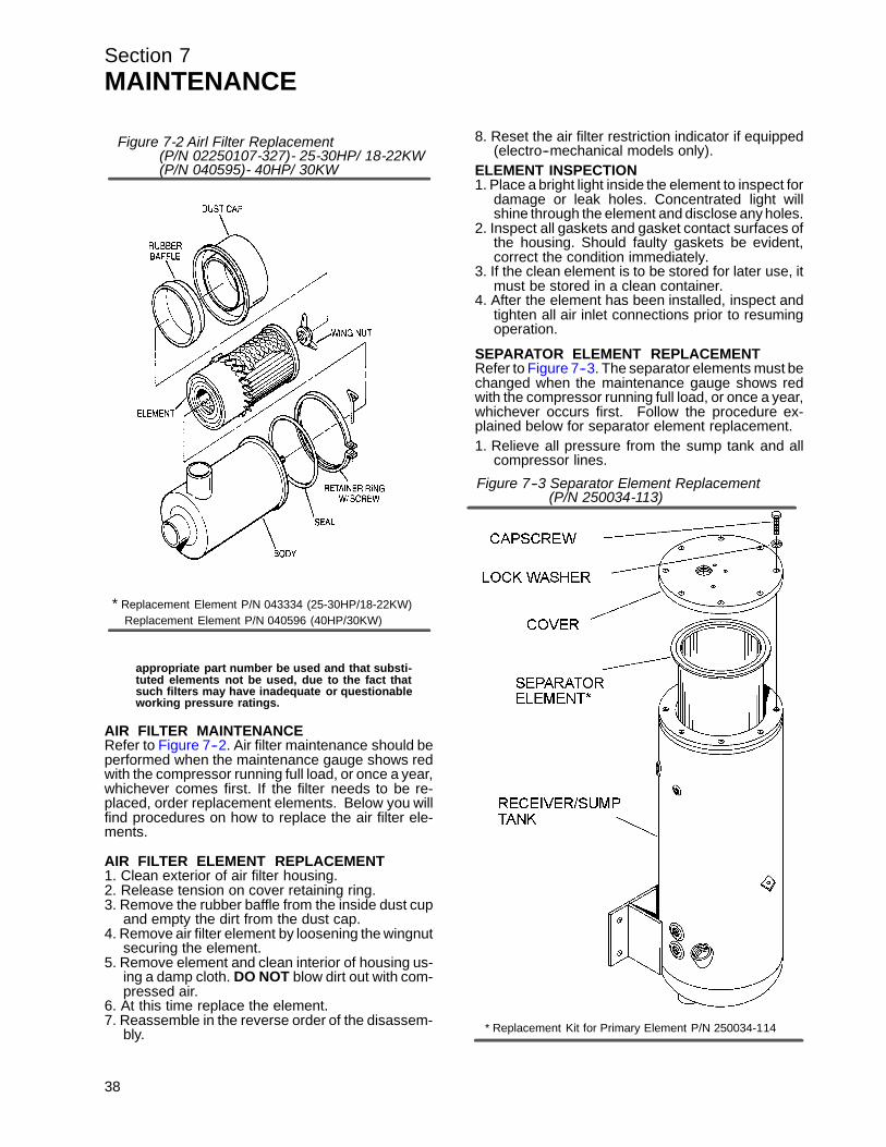
Section 7MAINTENANCE
appropriate part number be used and that substi-tuted elements not be used, due to the fact thatsuch filters may have inadequate or questionableworking pressure ratings.
AIR FILTER MAINTENANCERefer t o F igur e 7 -- 2. Air f ilter maintenanc e s hould beperformed when the maintenance gauge shows redwith the compressor running full load, or once a year,whichever comes first. If the filter needs to be re-placed, order replacement elements. Below you willfind procedures on how to replace the air filter ele-ments.
AIR FILTER ELEMENT REPLACEMENT1. Clean exterior of air filter housing.2. Release tension on cover retaining ring.3. Remove the rubber baffle from the inside dust cup
and empty the dirt from the dust cap.4. Remove air filter element by loosening the wingnut
securing the element.5. Remove element and clean interior of housing us-
ing a damp cloth. DO NOT blow dirt out with com-pressed air.
6. At this time replace the element.7. Reassemble in the reverse order of the disassem-
bly.
38
8. Reset the air filter restriction indicator if equipped(electro--mechanical models only).
ELEMENT INSPECTION1. Place a bright light inside the element to inspect for
damage or leak holes. Concentrated light willshine through the element and disclose any holes.
2. Inspect all gaskets and gasket contact surfaces ofthe housing. Should faulty gaskets be evident,correct the condition immediately.
3. If the clean element is to be stored for later use, itmust be stored in a clean container.
4. After the element has been installed, inspect andtighten all air inlet connections prior to resumingoperation.
SEPARATOR ELEMENT REPLACEMENTRefer t o F igur e 7 -- 3. T he s epar ator elements mus t bechanged when the maintenance gauge shows redwith the compressor running full load, or once a year,whichever occurs first. Follow the procedure ex-plained below for separator element replacement.1. Relieve all pressure from the sump tank and all
compressor lines.
* Replacement Element P/N 043334 (25-30HP/18-22KW)Replacement Element P/N 040596 (40HP/30KW)
Figure 7-2 Airl Filter Replacement(P/N 02250107-327)- 25-30HP/ 18-22KW(P/N 040595)- 40HP/ 30KW
Figure 7--3 Separator Element Replacement
* Replacement Kit for Primary Element P/N 250034-114
(P/N 250034-113)

Section 7MAINTENANCE
2. Disconnect all piping connected to the sump coverto allow removal (return lines, service lines, etc.).
3. Loosen and remove the eight (8) hex head caps-crews (1/2--13 x 1 1/2”) from the cover plate.
4. Lift the cover plate from the sump.5. Remove the separator element.6. Inspect the receiver/sump tank for rust, dirt, etc.7. Scrape the old gasket material from the cover and
flange on the sump. Be careful not to let thescraps fall in the sump.
8. Reinsert the separator element into the sump tak-ing care not to dent the element against the tankopening.
9. Clean the underside of the receiver/sump tankcover and remove any rust.
10. Replace the cover plate, washers and capscrews.Torque to 55 ft--lbs. (75 Nm).
11. Reconnect all piping making sure return line tubesextend to the bottom or 1/4” (6mm) above the bot-tom of the separator element. This will assureproper fluid return flow to the compressor.
12. Clean the return line strainers before restartingthe compressor.
CONTROL SYSTEM ADJUSTMENTRefer t o F igur e 7 -- 4. Pr ior t o adjus ting the C ontr olSystem, it is necessary to determine the desired op-erating pressure range and also the maximum pres-sure at which your compressor is to operate. Thepressure must not exceed the maximum operating
pressure which is stamped on the compressor serialnumber nameplate. The following explanation ap-plies to a typical installation with a desired operatingrange of 115 to 125 psig (7.9 to 8.6 bar). This informa-tion will apply to a compressor with any other operat-ing range excepting the stated pressures.
Remove the cover of the pressure switch. With theshut--off valve closed (or slightly cracked open) startthe compressor. Observe the line pressure gaugeand pressure switch contacts. When the line pres-sure reaches 125 psig (8.6 bar), the pressure switchcontacts should open. If the pressure switch con-tacts do not open or they open prior to the desiredpressure, the pressure switch setting will require ad-jus t ment ( r efer t o F igur e 7 -- 4) .
FOR PRESSURE RANGE ADJUSTMENT:1. Remove cover to pressure switch.2. Turn the range adjusting screw to the high pres-
sure setting. Turning the screw counterclockwiselowers both the high and low pressure equally.
FOR DIFFERENTIAL ADJUSTMENT:Differential is the difference between the high andlow pressure settings. 10 psig (0.7 bar) is typical.1. Turn the differential adjusting screw to the lower
(reset) setting. Turning the screw counterclock-wise widens the differential by lowering the reset(lower) setting only.
2. When the pressure switch adjustment is complete,the pressure regulator should be adjusted for thepressure at which modulation of air deliveryshould begin. In this case that pressure will be118 psig (8.2 bar). The regulator is adjusted byloosening the jam nut on the end of the coneshaped cover of the pressure regulator. When thejam nut is loose, turn the adjusting screw clock-wise to increase or counterclockwise to decreasethe setting.
3. To set the regulator, continue closing the servicevalve until the line pressure is 118 psig (8.2 bar).At this point regulator should pass a signal to theinlet valve to start closing it. If the line pressurekeeps on rising or if the modulation does not be-gin, adjust the regulator valve as describedabove. After adjustment, line pressure should beapproximately 118 psig (8.2 bar) and 1.00 in. Hg(2.54 cm Hg.) vacuum below the inlet.
4. Next, close the service valve; line pressure willstart rising. When line pressure reaches 125 psig(8.6 bar), the inlet valve will be closed to its maxi-mum position. The inlet vacuum at this point willbe around 25 in. Hg (63.5 cm Hg.). The machineshould unload at this point.
5. Open the service valve so the line pressure is 115psig (7.9 bar). Machine is now set for operation.Recheck the unload pressure by closing of theservice valve. Machine should unload via thepressure switch at 125 psig (8.6 bar).
After the control pressures have been adjusted, the“unloaded” sump pressure should be checked. It will
P/N 040694- StandardP/N 407778- High Pressure
Figure 7-4 Pressure Switch
39
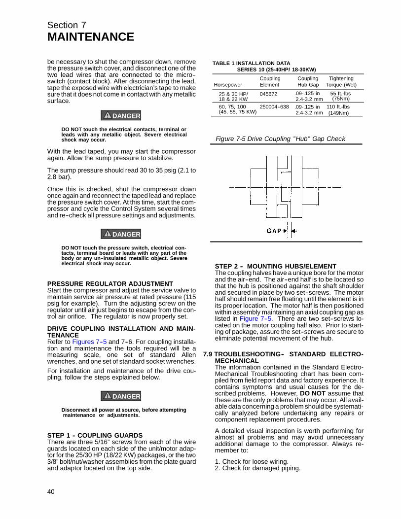
Section 7MAINTENANCE
be necessary to shut the compressor down, removethe pressure switch cover, and disconnect one of thetwo lead wires that are connected to the micro--switch (contact block). After disconnecting the lead,tape the exposed wire with electrician’s tape to makesure that it does not come in contact with any metallicsurface.
DANGER!
DO NOT touch the electrical contacts, terminal orleads with any metallic object. Severe electricalshock may occur.
With the lead taped, you may start the compressoragain. Allow the sump pressure to stabilize.
The sump pressure should read 30 to 35 psig (2.1 to2.8 bar).
Once this is checked, shut the compressor downonce again and reconnect the taped lead and replacethe pressure switch cover. At this time, start the com-pressor and cycle the Control System several timesand re--check all pressure settings and adjustments.
DANGER!
DO NOT touch the pressure switch, electrical con-tacts, terminal board or leads with any part of thebody or any un--insulated metallic object. Severeelectrical shock may occur.
PRESSURE REGULATOR ADJUSTMENTStart the compressor and adjust the service valve tomaintain service air pressure at rated pressure (115psig for example). Turn the adjusting screw on theregulator until air just begins to escape from the con-trol air orifice. The regulator is now properly set.
DRIVE COUPLING INSTALLATION AND MAIN-TENANCERefer t o F igur es 7 -- 5 and 7 -- 6. F or c oupling ins talla-tion and maintenance the tools required will be ameasuring scale, one set of standard Allenwrenches, and one set of standard socket wrenches.For installation and maintenance of the drive cou-pling, follow the steps explained below.
DANGER!
Disconnect all power at source, before attemptingmaintenance or adjustments.
STEP 1 -- COUPLING GUARDSThere are three 5/16” screws from each of the wireguards located on each side of the unit/motor adap-tor for the 25/30 HP (18/22 KW) packages, or the two3/8” bolt/nut/washer assemblies from the plate guardand adaptor located on the top side.
40
STEP 2 -- MOUNTING HUBS/ELEMENTThe coupling halves have a unique bore for the motorand the air--end. The air--end half is to be located sothat the hub is positioned against the shaft shoulderand secured in place by two set--screws. The motorhalf should remain free floating until the element is inits proper location. The motor half is then positionedwithin assembly maintaining an axial coupling gap aslis ted in F igur e 7 -- 5. T her e ar e two s et -- s c r ews lo-cated on the motor coupling half also. Prior to start-ing of package, assure the set--screws are secure toeliminate potential movement of the hub.
7.9 TROUBLESHOOTING-- STANDARD ELECTRO-MECHANICALThe information contained in the Standard Electro-Mechanical Troubleshooting chart has been com-piled from field report data and factory experience. Itcontains symptoms and usual causes for the de-scribed problems. However, DO NOT assume thatthese are the only problems that may occur. All avail-able data concerning a problem should be systemati-cally analyzed before undertaking any repairs orcomponent replacement procedures.
A detailed visual inspection is worth performing foralmost all problems and may avoid unnecessaryadditional damage to the compressor. Always re-member to:
1. Check for loose wiring.2. Check for damaged piping.
TABLE 1 INSTALLATION DATA
HorsepowerCouplingElement
CouplingHub Gap
TighteningTorque (Wet)
25 & 30 HP/ 045672 .09-.125 in 55 ft.-lbs
60, 75, 100 250004--638 110 ft.-lbs
(75Nm)
(149Nm)
18 & 22 KW
(45, 55, 75 KW).09-.125 in
SERIES 10 (25-40HP/ 18-30KW)
2.4-3.2 mm
2.4-3.2 mm
Figure 7-5 Drive Coupling ”Hub” Gap Check

Section 7MAINTENANCE
3. Check for parts damaged by heat or an electricalshort circuit, usually apparent by discoloration ora burnt odor.
Should your problem persist after making the recom-mended check, consult your nearest Sullair repre-sentative.
TROUBLESHOOTING-- STANDARD ELECTRO-MECHANICAL
SYMPTOM PROBABLE CAUSE REMEDY
COMPRESSOR WILL NOT START Main Disconnect Switch Open Close switch.
Line Fuse Blown Replace fuse.
Control Transformer Fuse Blown Replace fuse.
Motor Starter Overloads Tripped Reset. Should trouble persist, checkwhether motor starter contacts arefunctioning properly.
Low Incoming Line Voltage Check voltage. Should voltage check low,consult power company.
COMPRESSOR SHUTS DOWN WITH Loss of Control Voltage Reset. If trouble persists, check that lineAIR DEMAND PRESENT pressure does not exceed maximum oper--
ating pressure of the compressor (specifiedon nameplate).
Low Incoming Voltage Consult power company.
Excessive Operating Pressure Defect in line pressure switch; check pressureat which contact points open.Separator requires maintenance; checkmaintenance indicator under full load condi--tions.High pressure shutdown switch is defective;replace.Defective valve; regulator valve shouldcause inlet valve to close when the pressureswitch contacts open. Repair if defective.Defective blowdown valve; blowdown valveshould exhaust sump pressure to 10 to15 psig (0.7 to 1.0 bar) when maximumoperating pressure is reached. Repair ifdefective.
Discharge Temperature Switch Open Cooling water temperature too high;increase water flow (water--cooled only).Cooling water flow insufficient; check waterlines and valves (water--cooled only).Cooler plugged; clean tubes. If pluggingpersists, install water conditioner(water--cooled only).Cooling air flow restricted; clean cooler andcheck for proper ventilation.Ambient temperature is too high; providesufficient ventilation.Low fluid level; add fluid.Clogged filter; change the fluid filter elementand change the bearing filter element ifmaintenance indicator shows red.Thermal valve not functioning properly;replace element.Water flow regulating valve not functioningproperly; change (water--cooled only).Defective discharge temperature switch;check for a short or open circuit to probeand correct wiring.
41

Section 7MAINTENANCE
TROUBLESHOOTING-- STANDARD ELECTRO-MECHANICAL (CONTINUED)
SYMPTOM PROBABLE CAUSE REMEDY
COMPRESSOR WILL NOT BUILD Air Demand is Too Great Check service lines for leaks or open valves upFULL DISCHARGE PRESSURE.
Dirty Air Filter Check the filter indicator and inspect and/orchange element if required.
Pressure Regulator Out of Adjustment Adjust regulator according to controladjustment instructions in the Maintenancesection.
Defective Pressure Regulator Check diaphragm and replace if necessary(kit available).
LINE PRESSURE RISES ABOVE Leak in Control System Causing Check for leaks.CUT--OUT PRESSURE SETTING Loss of Pressure SignalsON PRESSURE SWITCH
Defective Pressure Switch Check that diaphragm and contacts are notdamaged. Replace if necessary.
Defective Regulator Valve Check that air bleeds from control orificewhen the pressure switch contacts open.Readjust; Repair or replace it if necessary (kit available).
Plugged Control Line Strainer Clean strainer (screen and o-ring replacement kitavailable).
Defective Blowdown Valve Check that sump pressure is exhausted tothe atmosphere when the pressure switchcontacts open. Repair or replace if neces--sary (kit available).
High Pressure Shutdown Switch is Readjust or replace.Defective or Incorrectly Adjusted
EXCESSIVE COMPRESSOR FLUID Clogged Return Line or Orifice Clean strainer (screen and o--ring replace--CONSUMPTION ment kit available).
Clean orifice.Separator Element Damaged orNot Functioning Properly Change separator.
Leak in the Lubrication System Check all pipes, connections and compo--nents.
Excess Fluid Foaming Drain and change.
Fluid Level Too High Drain and change.
PRESSURE RELIEF VALVE OPEN Defective Pressure Relief Valve Replace.REPEATEDLY
Plugged Separator Check separator differential.
LIQUID WATER IN COMPRESSED Water Vapor Condensation from Cooling Remove the water vapor from compressed air priorAIR LINES and Compression Occurs Naturally to distribution through the air system. Check opera--
tion of aftercooler and moisture separator. Install acompressed air dryer sized for the flow and drynesslevel required. (Note: Filters may also be required toremove particulates, liquid oil aerosols or for oil vaporremoval. Change cartridges as recommended by thefilter manufacturer). Check all drain traps routinelyto insure their proper operation. Maintain them regu--larly.
7.10 TROUBLESHOOTING-- SUPERVISOR IIThe information contained in the Supervisor II Trou-bleshooting chart is based upon both the actual ap-plied situations and extensive testing at the factory. It
42
contains symptoms and usual causes for the de-scribed problems. However, DO NOT assume thatthese are the only problems that may occur. All avail-able data concerning a problem should be systemati-

Section 7MAINTENANCE
cally analyzed before undertaking any repair or com-ponent replacement procedures.
A detailed visual inspection is worth performing foralmost any problems which may prevent unneces-sary damage to the compressor. Always rememberto:a. Check for loose wiring.
b. Check for damaged piping.c. Check for parts damaged by heat or an electrical
short circuit, usually apparent by discoloration ora burnt odor.
Should your problem persist after making the recom-mended check, consult your nearest Sullair repre-sentative or the Sullair Corporation factory.
TROUBLESHOOTING -- SUPERVISOR II
SYMPTOM (DISPLAY) PROBABLE CAUSE REMEDY
T1 HI Message Discharge Temperature Exceeded225_F (107_C) for Pre--Alarm
Discharge Temperature Exceeded235_F (113_C) for Shutdown
Ambient Temperature Exceeded Improve local ventilation (i.e.,105_F (41_C) remote intake of process and/or
cooling air).
Fluid Level in Sump is Too Low Check/correct fluid level.
Thermal Valve Malfunctioned Check/replace thermal valve.
Cooler Fins are Dirty (Air--cooled only) Clean cooler fins.
Water Flow is Low (Water--cooled Check cooling water supply (i.e.,Packages Only) closed valves).
Water Temperature is High (Water-- Increase water flow, lower waterCooled Packages Only) temperature.
Cooler is Plugged (Water--Cooled Clean tubes and/or shell -- if tubePackages Only) plugging persists, provide cleaner
water.
T1 FAIL Temperature RTD Malfunction Check connections from RTD.If connection is good, replace RTD.
P1 HI Message Discharge Pressure ExceededShutdown Level Because:
P1 MAX--3psi (0.2 Bar) Exceededfor Pre--Alarm
P1 MAX Exceeded for Shutdown
Unloading Device (i.e., Blowdown Check operation of unloading device.Valve) Failed to Operate
Pressure Regulator Adjusted Incorrectly Check operation of pressure regulator.
Solenoid Valve Failed Check operation of solenoid valve.to Operate
Control Air Signal Leaks Check tubework feeding controlsignal for leaks.
Control Air Signal Filter Clogged Service filter assembly.
P1, P2, P3 FAIL Pressure Transducer Malfunction Check connections from transducer.If connections are good, replace transducer.
P3 LOW Oil Pressure Falls Below 10 psig (0.7 bar)or Less than 1/2 of P1 while Compressoris Running Because:Oil Filter Clogged Replace filter element.Sump Oil Level Too Low Replenish oil level.
SEP MNTN Message Plugged Separator Replace separator element.
nP1 > 10 psi (0.7 Bar) Check P1 & P2 pressure transducers.
43
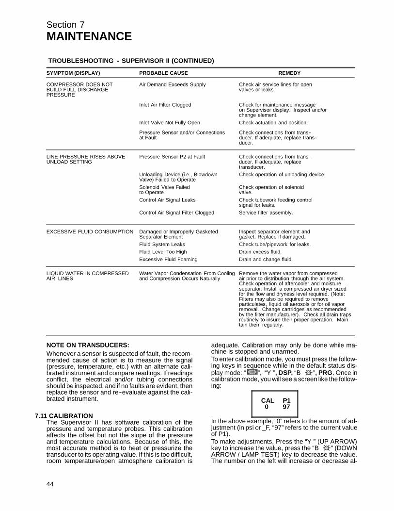
Section 7MAINTENANCE
TROUBLESHOOTING -- SUPERVISOR II (CONTINUED)
SYMPTOM (DISPLAY) PROBABLE CAUSE REMEDY
COMPRESSOR DOES NOT Air Demand Exceeds Supply Check air service lines for openBUILD FULL DISCHARGE valves or leaks.PRESSURE
Inlet Air Filter Clogged Check for maintenance messageon Supervisor display. Inspect and/orchange element.
Inlet Valve Not Fully Open Check actuation and position.
Pressure Sensor and/or Connections Check connections from trans--at Fault ducer. If adequate, replace trans--
ducer.
LINE PRESSURE RISES ABOVE Pressure Sensor P2 at Fault Check connections from trans--UNLOAD SETTING ducer. If adequate, replace
transducer.Unloading Device (i.e., Blowdown Check operation of unloading device.Valve) Failed to OperateSolenoid Valve Failed Check operation of solenoidto Operate valve.Control Air Signal Leaks Check tubework feeding control
signal for leaks.Control Air Signal Filter Clogged Service filter assembly.
EXCESSIVE FLUID CONSUMPTION Damaged or Improperly Gasketed Inspect separator element andSeparator Element gasket. Replace if damaged.Fluid System Leaks Check tube/pipework for leaks.Fluid Level Too High Drain excess fluid.Excessive Fluid Foaming Drain and change fluid.
LIQUID WATER IN COMPRESSED Water Vapor Condensation From Cooling Remove the water vapor from compressedAIR LINES and Compression Occurs Naturally air prior to distribution through the air system.
Check operation of aftercooler and moistureseparator. Install a compressed air dryer sizedfor the flow and dryness level required. (Note:Filters may also be required to removeparticulates, liquid oil aerosols or for oil vaporremoval. Change cartridges as recommendedby the filter manufacturer). Check all drain trapsroutinely to insure their proper operation. Main--tain them regularly.
NOTE ON TRANSDUCERS:Whenever a sensor is suspected of fault, the recom-mended cause of action is to measure the signal(pressure, temperature, etc.) with an alternate cali-brated instrument and compare readings. If readingsconflict, the electrical and/or tubing connectionsshould be inspected, and if no faults are evident, thenreplace the sensor and re--evaluate against the cali-brated instrument.
7.11 CALIBRATIONThe Supervisor II has software calibration of thepressure and temperature probes. This calibrationaffects the offset but not the slope of the pressureand temperature calculations. Because of this, themost accurate method is to heat or pressurize thetransducer to its operating value. If this is too difficult,room temperature/open atmosphere calibration is
44
adequate. Calibration may only be done while ma-chine is stopped and unarmed.To enter calibration mode, you must press the follow-ing keys in sequence while in the default status dis-play mode: “ ”, “Y”, DSP, “B ”, PRG. Once incalibration mode, you will see a screen like the follow-ing:
CAL P1970
In the above example, “0” refers to the amount of ad-justment (in psi or _F, “97” refers to the current valueof P1).To make adjustments, Press the “Y” (UP ARROW)key to increase the value, press the “B ” (DOWNARROW / LAMP TEST) key to decrease the value.The number on the left will increase or decrease al-
Section 7MAINTENANCE
ways showing the total amount of adjustment. Maxi-mum adjustment is ! 7.
The DSP key exits, wiping out changes to the currentitem, while saving changes to any previous items.The PRG key saves the current item and advancesto the next. All temperatures and pressures may becalibrated individually.
45

Section 7MAINTENANCE
Figure 7---7 Piping and Instrumentation Diagram --- Standard
46
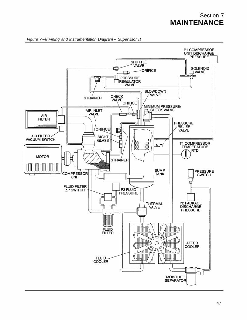
Section 7MAINTENANCE
Figure 7---8 Piping and Instrumentation Diagram--- Supervisor II
47

48
NOTES

Section 8ILLUSTRATIONS AND PARTS LIST
8.1 PROCEDURE FOR ORDERING PARTSParts should be ordered from the nearest Sullair Representative or the Representative from whom the compres-sor was purchased. If for any reason parts cannot be obtained in this manner, contact the factory directly at theaddresses, phone or fax numbers listed below.
When ordering parts always indicate the Serial Number of the compressor. This can be obtained from the Bill ofLading for the compressor or from the Serial Number Plate located on the compressor.
SULLAIR CORPORATION3700 East Michigan Boulevard
Michigan City, Indiana 46360 U.S.A.
SULLAIR ASIA, LTD.Sullair Road, No. 1Chiwan, Shekou
Shenzhen, Guangdong PRV.PRC POST CODE 518068
SULLAIR EUROPE, S.A.Zone Des Granges BP 82
42602 Montbrison Cedex, France
Telephone: 755-6851686Fax: 755-6853473
Telephone: 33-477968470Fax: 33-477968499
Telephone: 1-219-879-5451Fax: (219) 874-1273
Fax: (219) 874-1835 (Parts)Fax: (219) 874-1288 (Service)
8.2 RECOMMENDED SPARE PARTS LIST
DESCRIPTION KIT NUMBER QTY
element, compressor fluid filter 02250096--783 250025--525 1element, heavy duty air filter 02250107--327 (25--30HP/ 19--22KW) 043334 1element, heavy duty air filter 040595 (40HP/ 30 KW) 040596 1element, primary replacement for separator 250034--113 250034--114 1kit, repair for air inlet valve 02250088--348 250019--451 1kit, repair springs for air inlet valve 02250088--348 250029--315 1kit, repair for minimum pressure/check valve 02250097--609 02250110--988 1kit, repair cap for minimum pressure/check valve 02250097--609 02250046--397 1kit, repair o--ring for minimum pressure/check valve 02250097--609 02250048--362 1kit, repair piston for minimum pressure/check valve 02250097--609 02250051--338 1kit, repair thermal valve 02250096--738 (170_F) 250025--621 1kit, repair thermal valve 02250103--509 (190_F) 02250103--562 1kit, repair for pressure regulator 250017--280 250019--453 1kit, repair for blowdown valve 250025--655 250031--772 1kit, repair for solenoid valve 250038--674 (<= 140 psi/ 9.7 bar) 250038--673 1kit, replacement for solenoid valve coil 250038--674 (<= 140 psi/ 9.7 bar) 250031--738 1kit, repair for solenoid valve 250038--675 (>140 psi/ 9.7 bar) 02250055--939 1kit, replacement for solenoid valve coil 250038--675 (>140 psi/ 9.7 bar) 250038--730 1kit, repair inlet valve 02250088--348 250019--451 1kit, repair for v--type strainer 241771 241772 1kit, repair for shaft seal 001836--007 1element, replacement for combination separator/trap 02250078--841 02250081--108 1kit, repair automatic drain for combination separator/trap 02250078--841 02250087--422 1manual, Sequencing & Protocol (I) 02250057--696 1fluid, SRF 1/4000 (5 gallons) 250019--662 (II)lubricant, Sullube (std.) (5 gallons) 250022--669 (II)lubricant, 24 KT (5 gallons) 046850--001 (II)
(I) This document is required to program your personal computer to communicate with the Supervisor IIpanel.
(II) F or pr oper amount of fluid f ill, pleas e c ons ult Lubr ic ation G uide in Sec t ion 3, Spec ific ations .
PLEASE NOTE: WHEN ORDERING PARTS, ALWAYS INDICATE SERIAL NUMBER OF COMPRESSOR
49
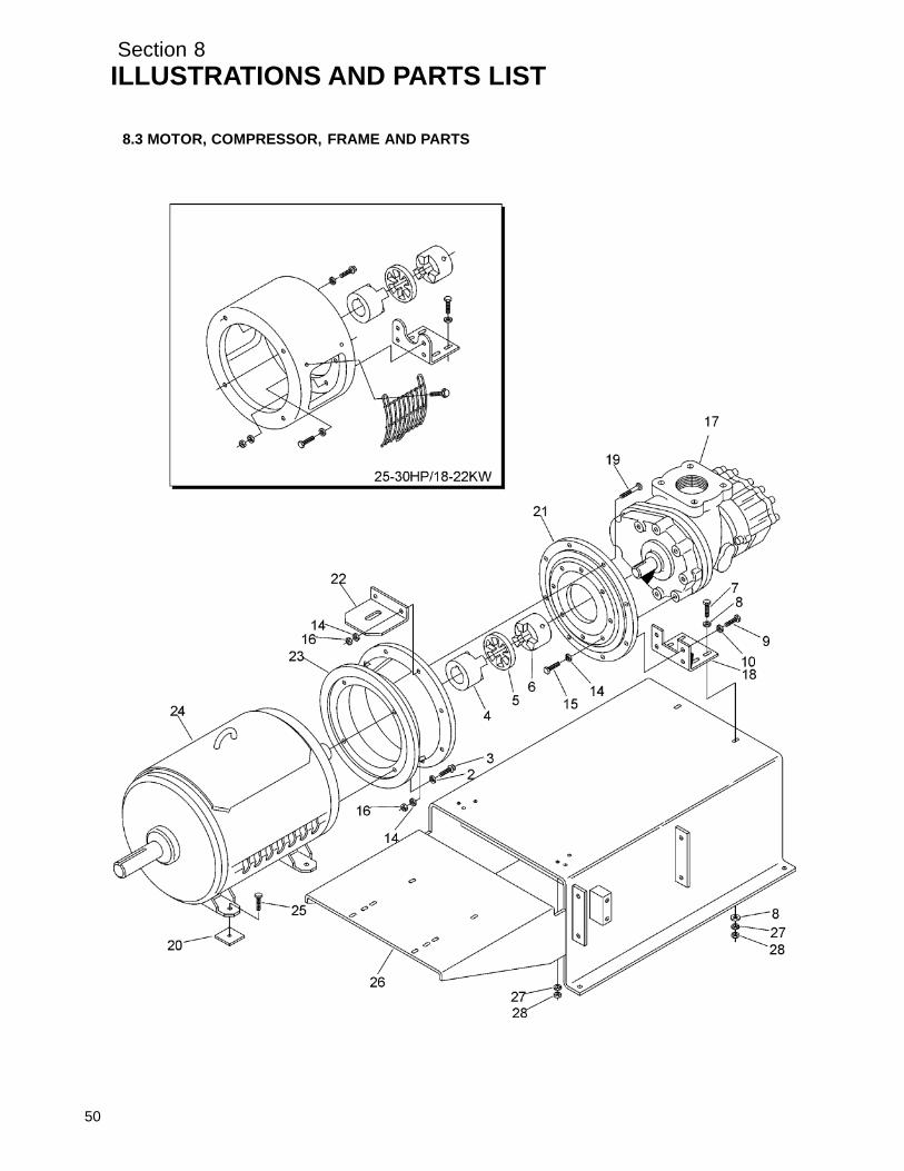
Section 8ILLUSTRATIONS AND PARTS LIST
5
8.3 MOTOR, COMPRESSOR, FRAME AND PARTS
0

Section 8ILLUSTRATIONS AND PARTS LIST
8.3 MOTOR, COMPRESSOR, FRAME AND PARTS
key partnumber description number quantity
1 adapter, motor (25, 30HP) 250038--448 12 washer, springlock reg pltd 1/2”
(25, 30HP) 837808--125 4Swasher, springlock reg pltd 5/8”(40HP) 837810--156 4
3 capscrew, ferry head 1/2”--13 x 1--1/4”(25, 30HP) 867308--125 4
capscrew, ferry head 5/8”--11 x 1--1/4”(40HP) 867310--150 4
4 hub, motor (25, 30HP) 045671 1Shub, motor (40HP) 250004--640 1
5 element, drive coupling (25, 30HP) 045672 1Selement, drive coupling (40HP) 250004--638 1
6 coupling, hub (25, 30HP) 045673 1Scoupling, hub (40HP) 250004--639 1
7 capscrew, hex gr5 1/2--13 x 1--1/2” 829108--150 28 washer, pl--b reg plated 1/2” 838208--112 49 capscrew, hex gr5 3/8”--16 x 2” 829106--200 2
10 washer, pl--b reg plated 3/8” 838206--112 211 angle, compressor mounting 02250103--594 112 screw, ser washer 5/16” x 3/4” 829705--075 613 grille, coupling guard 250038--863 214 washer, springlock reg plated 3/8”
(25, 30HP) 837806--094 9Swasher, springlock reg plated 3/8” (40HP) 837806--094 12
15 capscrew, hex gr5 3/8”--16 x 1--1/4” 829106--125 716 nut, hex plated 3/8”--16 (25, 30HP) 825206--337 2
wnut, hex plated 3/8”--16 (40HP) 825206--337 517 c ompr es s or unit c ons ult f ac tor y 118 angle, compressor mounting 02250107--610 119 capscrew, hex gr5 3/8”--16 x 1--3/4” 829106--175 3
(Continued on page 53)
(I) There is an exchange program whereby a remanufactured compressor unit can be obtained from Sullairdistributors or the factory at less cost than the owner could repair the unit. For information regarding theunit ex c hange pr ogr am, c ontac t y our near es t Sullair r epr es entativ e or t he Sullair Cor por ation.
The shaft seal is not considered part of the compressor unit in regard to the two year warranty. Thenormal Sullair parts warranty applies. For shaft seal repairs, order shaft seal repair kit no. 001836--007.
PLEASE NOTE: WHEN ORDERING PARTS, INDICATE SERIAL NUMBER OF COMPRESSOR
51

Section 8ILLUSTRATIONS AND PARTS LIST
52
8.3 MOTOR, COMPRESSOR, FRAME AND PARTS
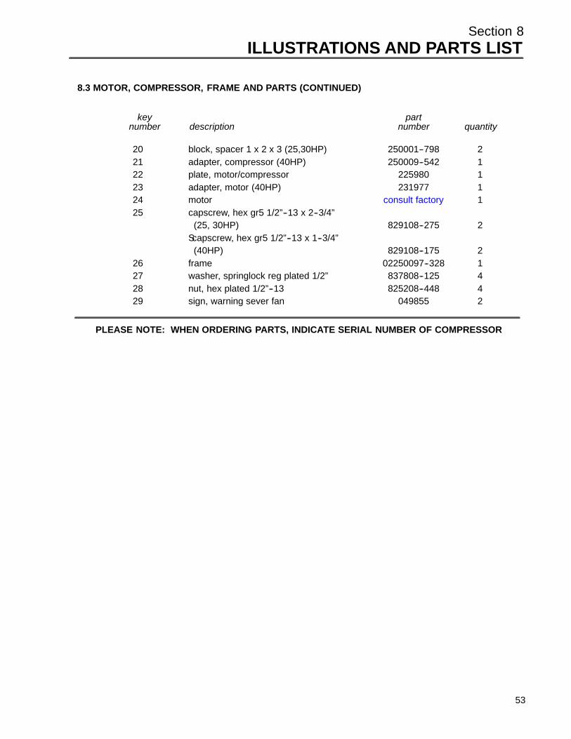
Section 8ILLUSTRATIONS AND PARTS LIST
8.3 MOTOR, COMPRESSOR, FRAME AND PARTS (CONTINUED)
key partnumber description number quantity
20 block, spacer 1 x 2 x 3 (25,30HP) 250001--798 221 adapter, compressor (40HP) 250009--542 122 plate, motor/compressor 225980 123 adapter, motor (40HP) 231977 124 motor c ons ult f ac tor y 125 capscrew, hex gr5 1/2”--13 x 2--3/4”
(25, 30HP) 829108--275 2Scapscrew, hex gr5 1/2”--13 x 1--3/4”
(40HP) 829108--175 226 frame 02250097--328 127 washer, springlock reg plated 1/2” 837808--125 428 nut, hex plated 1/2”--13 825208--448 429 sign, warning sever fan 049855 2
PLEASE NOTE: WHEN ORDERING PARTS, INDICATE SERIAL NUMBER OF COMPRESSOR
53

Section 8ILLUSTRATIONS AND PARTS LIST
8.4 COOLER ASSEMBLY
54

Section 8ILLUSTRATIONS AND PARTS LIST
8.4 COOLER ASSEMBLY
key partnumber description number quantity
1 screw, ser washer 5/16”--18 x 3/4” 829705--075 172 panel, cooler adapter (25, 30HP) 02250107--473 1
Spanel, cooler adapter (40HP) 02250107--548 13 nut, hex flanged plated 5/16”--18 825305--283 84 cooler, fluid ls--10 1--1/16” SAE 02250096--704 15 plate, cooler mtg frame extension 02250105--536 16 cooler, air/aftercooler (25, 30HP) 407106 1
Scooler, air/aftercooler (40HP) 250006--931 17 shroud, fan--17” (25, 30HP) 011994 1
wshroud, fan--18” (40HP) 013315 18 nut, retainer--u 5/16”--18 .140 861505--140 59 fan, 18”dia rh blower (25, 30HP) 042492 1
wfan, 17”dia rh blower (40HP) 249012 110 nut, hex locking plated 5/16”--18 (25, 30HP) 825505--166 4
Snut, hex locking plated 3/8”--16 (40HP) 825506--198 411 guard, fan shroud 225962 112 hub, fan mounting (25, 30HP) 023350 1
Shub, fan mounting (40HP) 231981 113 capscrew, ferry head 5/16”--18 x 1--1/2”
(25, 30HP) 828405--150 4Scapscrew, ferry head 3/8”--16 x 1--3/4”
(40HP) 828406--175 414 screw, set 5/16”--18 x 1/2” 250010--322 215 nut, hex flanged plated 5/16”--18 825305--283 216 screw. ser washer 5/16”--18 x 3/4” 829705--075 217 nut, retainer--u 5/16”--18 861505--140 4
PLEASE NOTE: WHEN ORDERING PARTS, INDICATE SERIAL NUMBER OF COMPRESSOR
55

Section 8ILLUSTRATIONS AND PARTS LIST
8.5 AIR INLET SYSTEM
56

Section 8ILLUSTRATIONS AND PARTS LIST
8.5 AIR INLET SYSTEM
key partnumber description number quantity
1 filter, air inlet heavy duty (25, 30HP) (I) 02250107--327 1wfilter, air inlet heavy duty (40HP) (II) 040595 1
2 indicator, maintenance 045757 13 band, mounting--inlet filter (25, 30HP) 043370 1
Sband, mounting--inlet filter (40HP) 040598 14 clamp, inlet elbow 250018--550 15 screw, ser washer 5/16”--18 x 3/4” 829705--075 26 connector, 1/4”tube x 1/8”npt 250018--427 17 tubing, nylon 1/4” black 02250054--861 --8 support, filter heavy duty 02250100--529 19 nut, hex flanged plated 5/16”--18 825305--283 2
10 elbow, rubber 90_ red 2--1/2” x 3” (25, 30HP) 250032--462 1Selbow, rubber 90_ 3” (40HP) 040599 1
11 capscrew, hex gr5 5/8”--11 x 1--1/2” 829110--150 412 washer, springlock reg plated 5/8” 837810--156 413 valve, inlet control (III) 02250088--348 114 elbow, 1/4”tube x 1/4”npt 250018--430 115 o--ring, viton 826502--238 116 support, filter heavy duty 02250100--528 117 capscrew, hex gr5 5/16”--18 x 1--3/4” 829105--175 118 nut, hex flanged plated 5/16”--18 825305--283 119 lug, scrulug--ground 849215--025 120 capscrew, hex gr5 3/8”--16 x 1--3/4” 829106--175 121 washer, springlock reg plated 3/8” 837806--094 122 nut, hex plated 3/8”--16 825206--337 123 capscrew, hex gr5 3/8”--16 x 1--1/2” 829106--150 224 washer, springlock reg plated 3/8” 837806--094 225 nut, hex plated 3/8”--16 825206--337 226 clamp, inlet elbow (25, 30HP) 040083 1
Sclamp, inlet elbow (40HP) 250018--550 1
(I) For maintenance on air filter no. 02250107--327, order replacement element no. 043334.(II) For maintenance on air filter no. 040595, order replacement element no. 040596.(III) For maintenance on air inlet valve no. 02250088--348, order repair kit no. 250019--451, and/or repair kit for
springs no. 250029--315.
PLEASE NOTE: WHEN ORDERING PARTS, INDICATE SERIAL NUMBER OF COMPRESSOR
57

Section 8ILLUSTRATIONS AND PARTS LIST
8.6 COOLING AND LUBRICATION SYSTEM- AIR-COOLED
58

Section 8ILLUSTRATIONS AND PARTS LIST
8.6 COOLING AND LUBRICATION SYSTEM- AIR-COOLED
key partnumber description number quantity
1 cooler, fluid ls--10 1--1/16” SAE 02250096--704 12 elbow, tube straight thread 3/4” x 1--1/16” 811612--106 43 tube, 3/4” cooler/fluid filter 02250099--370 14 elbow, tube--m 1” x 3/4” (25, 30HP) 810516--075 2
Selbow, tube--m 1” x 1” (40HP) 810516--100 25 cooler, air/aftercooler (25, 30HP) 407106 1
Scooler, air/aftercooler (40HP) 250006--931 16 tube, aftercooler/moisture separator 02250100--730 17 tube, minimum pressure valve/aftercooler 02250099--372 18 connector, tube--m 1” x 1” 810216--100 19 bushing, reducing hex 1--1/2” x 1” plated 868906--040 1
10 separator, moisture 1--1/2”npt (I) 02250078--841 111 U--bolt, 3/8” x 1--1/2” pipe plated 868306--150 112 nipple, pipe xs 1/2” x 4” 866424--040 113 tee, reducing 1--1/2” x 1/2” x 1--1/2” plated 867506--026 114 transducer, pressure 0--250psi 1--5dvc N4 02250078--933 115 bushing, reducing 1/2” x 1/8” plated 868902--005 116 connector, tube--m 1/4” x 1/8” nylon 250018--427 117 tubing, nylon 1/4” black 02250054--861 --18 washer, springlock reg plated 3/8” 837806--094 219 clamp, tube rubber center 1--3/8” dia 2500025--638 120 support, bracket moisture separator ls10 02250100--634 121 screw, ser washer 5/16”--18 x 3/4” 829705--075 322 connector, SAE x ORFS 0.75” 02250099--765 223 hose, mp ORFS f--swivel end .75” x 45” 02250099--175 124 reducer, straight thread 1--1/4” x 3/4” viton 870020--012 225 filter, fluid 1--5/8” SAE connection (II) 02250096--783 126 connector, tube 1/8M x 1/4T stainless steel 250139--024 127 elbow, tube 1/8M x 1/4T stainless steel 250211--013 128 tubing, stainless steel 1/4” 20ga 841215--004 --29 tee, tube--run straight thread 3/4” x 1--1/16” 811912--106 130 tube, fluid filter/thermal valve 02250099--367 131 connector, tube straight thread
3/4” x 1--1/16” 811812--106 232 tube, thermal valve/oil cooler 02250099--369 1
(Continued on page 61)
(I) For maintenance on moisture separator no. 02250078--841, order replacement element no.02250081--108, and automatic drain no. 02250087--422.
(II) For maintenance on fluid filter no. 02250096--783, order replacement element no. 250025--525.
PLEASE NOTE: WHEN ORDERING PARTS, INDICATE SERIAL NUMBER OF COMPRESSOR
59

Section 8ILLUSTRATIONS AND PARTS LIST
60
8.6 COOLING AND LUBRICATION SYSTEM- AIR-COOLED

Section 8ILLUSTRATIONS AND PARTS LIST
8.6 COOLING AND LUBRICATION SYSTEM- AIR-COOLED (CONTINUED)
key partnumber description number quantity
33 valve, thermal (170_F) (III) 02250096--738 1Svalve, thermal (190_F) (IV) 02250103--509 1
34 tube, flexible tank/thermal valve ls10 02250100--616 135 screw, ser washer 5/16”--18 x 3/4” 829705--075 436 support, bracket oil filter 02250103--970 137 transducer, pressure 0--250psi 1--5dvc N4 02250078--933 138 switch, pressure differential 20psid 02250050--154 139 elbow, tube 1/8”M x 1/4”T stainless steel 250211--013 240 tee, tube 1/8F x 1/8M x 1/8F 02250077--903 141 connector, tube 1/8”M x 1/4”T stainless steel 250139--024 2
(III) For maintenance on thermal valve (170_F) no. 02250096--738, order repair kit no. 250025--621.
(IV) For maintenance on thermal valve (190_F) no. 02250103--509, order repair kit no. 02250103--562.
PLEASE NOTE: WHEN ORDERING PARTS, INDICATE SERIAL NUMBER OF COMPRESSOR
61

Section 8ILLUSTRATIONS AND PARTS LIST
8.7 COOLING AND LUBRICATION SYSTEM- WATER-COOLED 25 & 30HP/ 18 & 22KW
62

Section 8ILLUSTRATIONS AND PARTS LIST
8.7 COOLING AND LUBRICATION SYSTEM- WATER-COOLED 25 & 30HP/ 18 & 22KW
key partnumber description number quantity
1 tube,nylon .25”od x .04w black 02250054--861 4 ft2 tee,sae/npt oil return 02250085--979 13 adapter, sae 1 5/16 x 1 5/16--12 02250086--022 14 filter, fluid 1 5/8 sae str thrd con (I) 02250096--783 15 hose, medium pressure orfs
f--swvl end 45”long 02250099--175 16 connector,sae x orfs 0.75” 02250099--765 47 support, bracket oil filt ls--10 l.f. 02250103--970 18 tube,1”od clr/tank 25/30hp 02250110--168 19 cooler, heat exchanger std sae ports 02250110--238 1
10 support, bracket w.o.clr ls--10--lf 02250110--454 111 tube, flexible tank/w.o.c. 3/4” 02250110--456 112 hose, medium pressure orfs
f--swvl 3/4”x 31” 90 02250113--370 113 tube,wc/moist sep ls10 02250113--436 114 clamp, exhaust 3 1/2” 040284 215 valve, water regulator 1/2” 041265 116 clamp, exhaust 4 1/2” 041983 217 heat exchanger, 3 x 24 25/30hp 043096 118 switch, pressure n.o. 10 psi 250017--992 119 elbow, 90 1/4t pls x 1/8 npt m 250018--429 120 elbow, 90 1/4t pls x 1/4 npt m 250018--430 121 clamp, tube rubber 1--3/8”F 250025--638 122 tubing, nylon 3/4”od 250039--353 3 ft23 connector,male plastic tubing 3/4” x 3/4 250039--357 224 union, pipe galv 1/2 802315--020 125 connector, tube--m 1 x 1 810216--100 226 elbow, tube 90 deg m 1 x 1 810516--100 127 elbow, tube str thrd 3/4 x 1 1/16 811612--106 128 connector, tube str thd 3/4 x 1 5/16 811812--116 129 nut,hex f pltd 5/16--18 825305--283 430 screw, hex ser washer 5/16--18 x 3/4 829705--075 931 locknut, conduit 1/2” 847200--050 132 elbow, pipe--90m 3/4 x 1/2 860512--050 133 elbow, pipe 90 deg plt 3/4” 866215--030 234 nipple,pipe--xs plt 1/2 x cl 866408--000 135 plug, pipe 1/4” 3000# stl plt 866900--010 1
(Continued on page 65)
(I) For maintenance on fluid filter no. 02250096--783, order replacement element no. 250025--525.
PLEASE NOTE: WHEN ORDERING PARTS, INDICATE SERIAL NUMBER OF COMPRESSOR
63
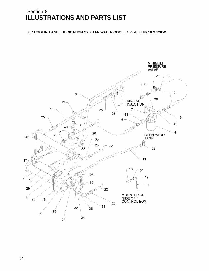
Section 8ILLUSTRATIONS AND PARTS LIST
64
8.7 COOLING AND LUBRICATION SYSTEM- WATER-COOLED 25 & 30HP/ 18 & 22KW

Section 8ILLUSTRATIONS AND PARTS LIST
8.7 COOLING AND LUBRICATION SYSTEM- WATER-COOLED 25 & 30HP/ 18 & 22KW (CONTINUED)
key partnumber description number quantity
36 tee, reducing pltd 1/2 x 1/4 x 1/2 867502--012 137 nipple,pipe--hx pltd 1/2 x 1/2 868508--050 138 nipple,pipe--hx pltd 3/4 x 3/4 868512--075 239 bushing,red hex pltd 1 1/2 x 1 868906--040 140 reducer,str thrd viton 1 x 3/4 870016--012 141 reducer,str thrd viton 1 1/4 x 3/4 870020--012 2
PLEASE NOTE: WHEN ORDERING PARTS, INDICATE SERIAL NUMBER OF COMPRESSOR
65

Section 8ILLUSTRATIONS AND PARTS LIST
8.8 COOLING AND LUBRICATION SYSTEM- WATER-COOLED 40HP/ 30KW
66
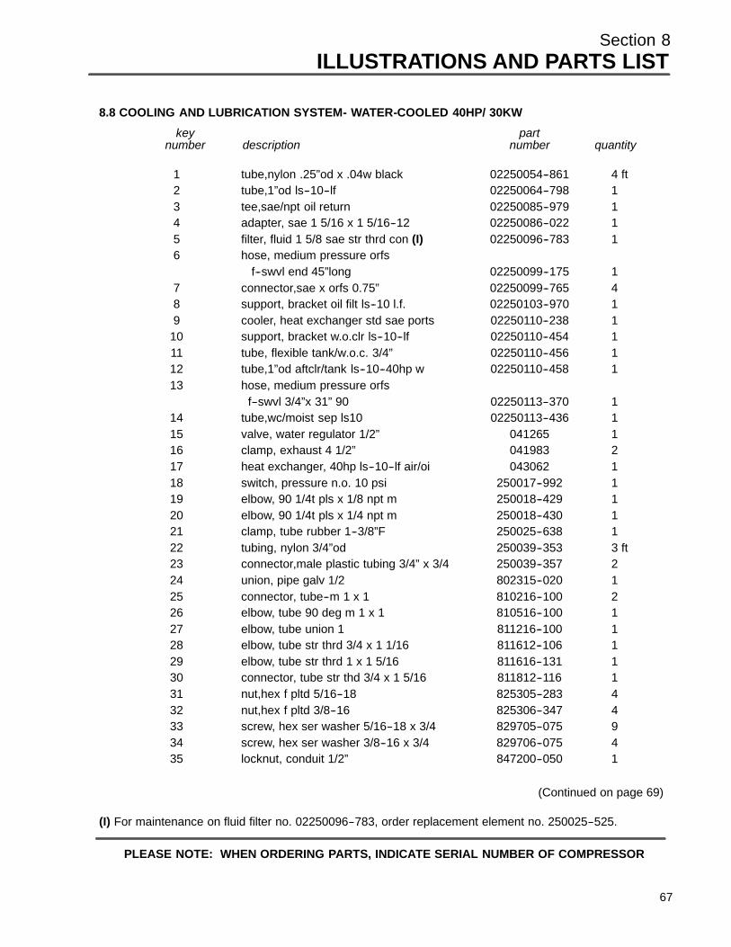
Section 8ILLUSTRATIONS AND PARTS LIST
8.8 COOLING AND LUBRICATION SYSTEM- WATER-COOLED 40HP/ 30KW
key partnumber description number quantity
1 tube,nylon .25”od x .04w black 02250054--861 4 ft2 tube,1”od ls--10--lf 02250064--798 13 tee,sae/npt oil return 02250085--979 14 adapter, sae 1 5/16 x 1 5/16--12 02250086--022 15 filter, fluid 1 5/8 sae str thrd con (I) 02250096--783 16 hose, medium pressure orfs
f--swvl end 45”long 02250099--175 17 connector,sae x orfs 0.75” 02250099--765 48 support, bracket oil filt ls--10 l.f. 02250103--970 19 cooler, heat exchanger std sae ports 02250110--238 1
10 support, bracket w.o.clr ls--10--lf 02250110--454 111 tube, flexible tank/w.o.c. 3/4” 02250110--456 112 tube,1”od aftclr/tank ls--10--40hp w 02250110--458 113 hose, medium pressure orfs
f--swvl 3/4”x 31” 90 02250113--370 114 tube,wc/moist sep ls10 02250113--436 115 valve, water regulator 1/2” 041265 116 clamp, exhaust 4 1/2” 041983 217 heat exchanger, 40hp ls--10--lf air/oi 043062 118 switch, pressure n.o. 10 psi 250017--992 119 elbow, 90 1/4t pls x 1/8 npt m 250018--429 120 elbow, 90 1/4t pls x 1/4 npt m 250018--430 121 clamp, tube rubber 1--3/8”F 250025--638 122 tubing, nylon 3/4”od 250039--353 3 ft23 connector,male plastic tubing 3/4” x 3/4 250039--357 224 union, pipe galv 1/2 802315--020 125 connector, tube--m 1 x 1 810216--100 226 elbow, tube 90 deg m 1 x 1 810516--100 127 elbow, tube union 1 811216--100 128 elbow, tube str thrd 3/4 x 1 1/16 811612--106 129 elbow, tube str thrd 1 x 1 5/16 811616--131 130 connector, tube str thd 3/4 x 1 5/16 811812--116 131 nut,hex f pltd 5/16--18 825305--283 432 nut,hex f pltd 3/8--16 825306--347 433 screw, hex ser washer 5/16--18 x 3/4 829705--075 934 screw, hex ser washer 3/8--16 x 3/4 829706--075 435 locknut, conduit 1/2” 847200--050 1
(Continued on page 69)
(I) For maintenance on fluid filter no. 02250096--783, order replacement element no. 250025--525.
PLEASE NOTE: WHEN ORDERING PARTS, INDICATE SERIAL NUMBER OF COMPRESSOR
67
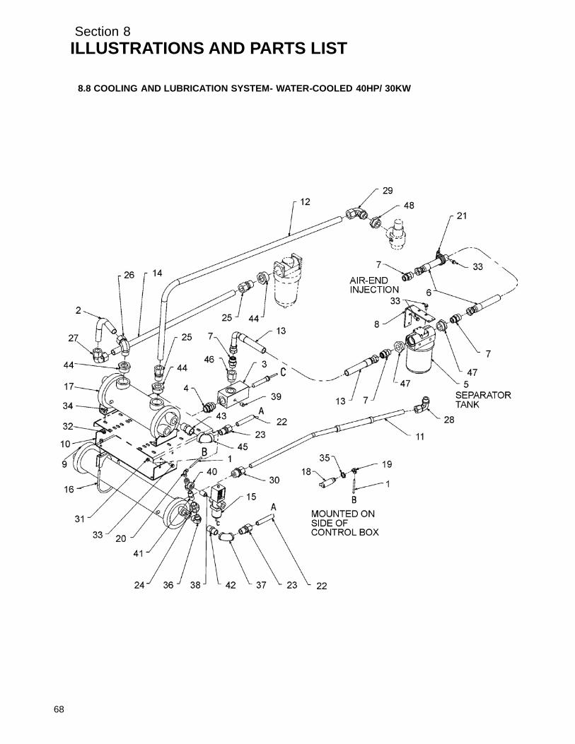
Section 8ILLUSTRATIONS AND PARTS LIST
68
8.8 COOLING AND LUBRICATION SYSTEM- WATER-COOLED 40HP/ 30KW

Section 8ILLUSTRATIONS AND PARTS LIST
8.8 COOLING AND LUBRICATION SYSTEM- WATER-COOLED 40HP/ 30KW (CONTINUED)
key partnumber description number quantity
36 elbow, pipe--90m 3/4 x 1/2 860512--050 137 elbow, pipe 90 deg plt 3/4” 866215--030 138 nipple,pipe--xs plt 1/2 x cl 866408--000 139 plug, pipe 1/4” 3000# stl plt 866900--010 140 tee, reducing pltd 1/2 x 1/4 x 1/2 867502--012 141 nipple,pipe--hx pltd 1/2 x 1/2 868508--050 142 nipple,pipe--hx pltd 3/4 x 3/4 868512--075 143 nipple,pipe--hx pltd 1 x 1 868516--100 144 bushing,red hex pltd 1 1/2 x 1 868906--040 345 elbow, red 1 x 3/4 150# plt 869204--030 146 reducer,str thrd viton 1 x 3/4 870016--012 147 reducer,str thrd viton 1 1/4 x 3/4 870020--012 248 reducer,str thrd viton 1 1/4 x 1 870020--016 1
PLEASE NOTE: WHEN ORDERING PARTS, INDICATE SERIAL NUMBER OF COMPRESSOR
69

Section 8ILLUSTRATIONS AND PARTS LIST
70
8.9 DISCHARGE SYSTEM

Section 8ILLUSTRATIONS AND PARTS LIST
8.9 DISCHARGE SYSTEM
key partnumber description number quantity
1 connector, 1/4”tube x 1/4”npt 250018--428 12 elbow, tube--m 1/4”t x 1/8”p stainless steel 250211--013 13 tube, stainless steel 1/4” 20ga 841215--004 --4 tube, nylon 1/4” black 02250054--861 --5 elbow, tube--m 1/4” stainless steel 250211--005 16 glass, sight--in line 1/4”npt 046559 17 orifice, .094” 1/4”npt steel 022033 18 strainer, v--type 300psi x 1/4”npt (I) 241771 19 connector, tube--male bulkhead 1/4”t x 1/4”p
ststl 870204--025 110 support, bracket--oil return 02250101--192 111 capscrew, hex gr5 1/2”--13 x 1--1/4” plated 829108--125 812 washer, springlock reg plated 1/2” 837808--125 813 elbow, 1/4”tube x 1/4”npt 250018--430 314 valve, check 1/4” nptf brass viton seal 02250115--272 115 tee, pipe 1/4” male npt 869825--025 116 elbow, female 1/4”npt x 1/4”T 250041--287 117 orifice, .125” x 1/4”mnpt x 1/4”fnpt 02250046--537 118 valve, blowdown 1/4” npt 02250049--634 119 nipple, pipe 1/4”npt hex 868504--025 120 connector, flex 1/4”t x 1/4”p 020169 121 plug, pipe 1/8”npt 3000# plated 866900--005 122 valve, minimum pressure check 1--5/8”
SAE (II) 02250097--609 123 connector, tube--straight thread 1” x 1--5/8” 811816--163 124 tube, minimum pressure valve/aftercooler 02250099--372 125 adapter, SAE 1--5/8”--12 x 1--5/8”--12 02250055--015 126 element, separator--primary (III) 250034--113 127 tank, separator air/oil 10”dia SAE/ISO 02250096--708 128 valve, pressure relief 1/2”npt 200# 250006--938 129 elbow, tube--m straight thread ss 1/4” x 7/16” 870807--025 130 elbow, tube straight thread 1--1/2” x 1--7/8” 811624--188 2
(Continued on page 73)
(I) For maintenance on strainer no. 241771, order repair kit no. 241772.(II) For maintenance on minimum pressure check valve no. 02250097--609, order repair kit no. 250026--758;
repair kit (for cap) no. 02250046--397; repair kit (for o--ring) no. 02250048--362; repair kit (for piston) no.02250051--338.
(III) For maintenance on separator element, order replacement element no. 250034--114.
PLEASE NOTE: WHEN ORDERING PARTS, INDICATE SERIAL NUMBER OF COMPRESSOR
71

Section 8ILLUSTRATIONS AND PARTS LIST
72
8.9 DISCHARGE SYSTEM
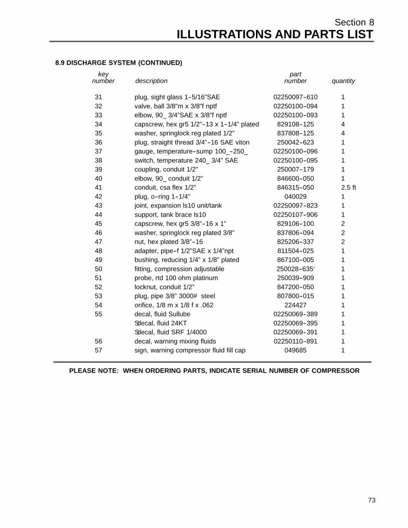
Section 8ILLUSTRATIONS AND PARTS LIST
8.9 DISCHARGE SYSTEM (CONTINUED)
key partnumber description number quantity
31 plug, sight glass 1--5/16”SAE 02250097--610 132 valve, ball 3/8”m x 3/8”f nptf 02250100--094 133 elbow, 90_ 3/4”SAE x 3/8”f nptf 02250100--093 134 capscrew, hex gr5 1/2”--13 x 1--1/4” plated 829108--125 435 washer, springlock reg plated 1/2” 837808--125 436 plug, straight thread 3/4”--16 SAE viton 250042--623 137 gauge, temperature--sump 100_--250_ 02250100--096 138 switch, temperature 240_ 3/4” SAE 02250100--095 139 coupling, conduit 1/2” 250007--179 140 elbow, 90_ conduit 1/2” 846600--050 141 conduit, csa flex 1/2” 846315--050 2.5 ft42 plug, o--ring 1--1/4” 040029 143 joint, expansion ls10 unit/tank 02250097--823 144 support, tank brace ls10 02250107--906 145 capscrew, hex gr5 3/8”--16 x 1” 829106--100 246 washer, springlock reg plated 3/8” 837806--094 247 nut, hex plated 3/8”--16 825206--337 248 adapter, pipe--f 1/2”SAE x 1/4”npt 811504--025 149 bushing, reducing 1/4” x 1/8” plated 867100--005 150 fitting, compression adjustable 250028--635‘ 151 probe, rtd 100 ohm platinum 250039--909 152 locknut, conduit 1/2” 847200--050 153 plug, pipe 3/8” 3000# steel 807800--015 154 orifice, 1/8 m x 1/8 f x .062 224427 155 decal, fluid Sullube 02250069--389 1
Sdecal, fluid 24KT 02250069--395 1Sdecal, fluid SRF 1/4000 02250069--391 1
56 decal, warning mixing fluids 02250110--891 157 sign, warning compressor fluid fill cap 049685 1
PLEASE NOTE: WHEN ORDERING PARTS, INDICATE SERIAL NUMBER OF COMPRESSOR
73

Section 8ILLUSTRATIONS AND PARTS LIST
8.10 CONTROL SYSTEM AND ELECTRICAL PARTS
74
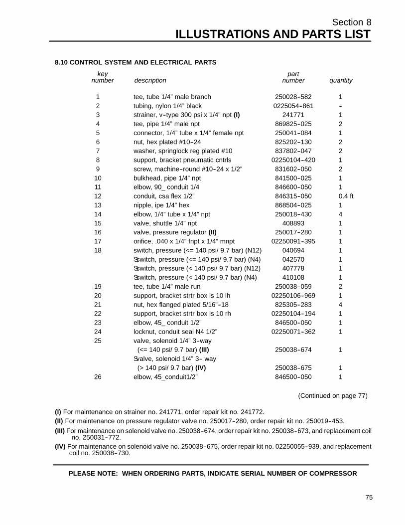
Section 8ILLUSTRATIONS AND PARTS LIST
8.10 CONTROL SYSTEM AND ELECTRICAL PARTS
key partnumber description number quantity
1 tee, tube 1/4” male branch 250028--582 12 tubing, nylon 1/4” black 0225054--861 --3 strainer, v--type 300 psi x 1/4” npt (I) 241771 14 tee, pipe 1/4” male npt 869825--025 25 connector, 1/4” tube x 1/4” female npt 250041--084 16 nut, hex plated #10--24 825202--130 27 washer, springlock reg plated #10 837802--047 28 support, bracket pneumatic cntrls 02250104--420 19 screw, machine--round #10--24 x 1/2” 831602--050 2
10 bulkhead, pipe 1/4” npt 841500--025 111 elbow, 90_ conduit 1/4 846600--050 112 conduit, csa flex 1/2” 846315--050 0.4 ft13 nipple, ipe 1/4” hex 868504--025 114 elbow, 1/4” tube x 1/4” npt 250018--430 415 valve, shuttle 1/4” npt 408893 116 valve, pressure regulator (II) 250017--280 117 orifice, .040 x 1/4” fnpt x 1/4” mnpt 02250091--395 118 switch, pressure (<= 140 psi/ 9.7 bar) (N12) 040694 1
Sswitch, pressure (<= 140 psi/ 9.7 bar) (N4) 042570 1Sswitch, pressure (< 140 psi/ 9.7 bar) (N12) 407778 1Sswitch, pressure (< 140 psi/ 9.7 bar) (N4) 410108 1
19 tee, tube 1/4” male run 250038--059 220 support, bracket strtr box ls 10 lh 02250106--969 121 nut, hex flanged plated 5/16”--18 825305--283 422 support, bracket strtr box ls 10 rh 02250104--194 123 elbow, 45_ conduit 1/2” 846500--050 124 locknut, conduit seal N4 1/2” 02250071--362 125 valve, solenoid 1/4” 3--way
(<= 140 psi/ 9.7 bar) (III) 250038--674 1Svalve, solenoid 1/4” 3-- way
(> 140 psi/ 9.7 bar) (IV) 250038--675 126 elbow, 45_conduit1/2” 846500--050 1
(Continued on page 77)
(I) For maintenance on strainer no. 241771, order repair kit no. 241772.(II) For maintenance on pressure regulator valve no. 250017--280, order repair kit no. 250019--453.(III) For maintenance on solenoid valve no. 250038--674, order repair kit no. 250038--673, and replacement coil
no. 250031--772.(IV) For maintenance on solenoid valve no. 250038--675, order repair kit no. 02250055--939, and replacement
coil no. 250038--730.
PLEASE NOTE: WHEN ORDERING PARTS, INDICATE SERIAL NUMBER OF COMPRESSOR
75

Section 8ILLUSTRATIONS AND PARTS LIST
76
8.10 CONTROL SYSTEM AND ELECTRICAL PARTS

Section 8ILLUSTRATIONS AND PARTS LIST
8.10 CONTROL SYSTEM AND ELECTRICAL PARTS (CONTINUED)
key partnumber description number quantity
27 nipple, chase 1/2” 847815--050 128 box , elec t r ic al s tr tr ls 10 c ons ult f ac tor y 130 washer, springlock m4 838804--090 831 gasket, panel Supervisor II 02250048--822 132 controller, electro--mechanical 02250106--694 1
Scontroller, Supervisor II dlx 02250083--801 133 switch, emergency shut--off 02250085--504 1
PLEASE NOTE: WHEN ORDERING PARTS, INDICATE SERIAL NUMBER OF COMPRESSOR
77

Section 8ILLUSTRATIONS AND PARTS LIST
8.11 INSTRUMENT PANEL
78

Section 8ILLUSTRATIONS AND PARTS LIST
8.11 INSTRUMENT PANEL
key partnumber description number quantity
1 elbow, 90_ 1/4”t x 1/8” female npt 250041--286 22 tubing, nylon 1/4” black 02250054--861 --3 connector, tube--f 1/4”t x 1/8”p stainless steel 250139--050 24 tubing, stainless steel 1/4” 20ga 841215--004 --5 tee, adaptor 1/4”t x 1/8”m x 1/8”f 869704--012 16 elbow, tube--f 1/4”t x 1/8”p stainless steel 250211--030 17 connector, female 1/4”t x 1/8”npt 250021--379 18 panel, mounting gauge e/mdc 02250104--355 19 decal, instrument panel 10 series universal 02250060--034 1
10 gauge, differential pressure 0--30psi 250003--799 111 gauge, temperature 100_--250_F--3/4” SAE 02250100--096 112 gauge, differential pressure 0--15psi 250003--798 113 gauge, pressure 2” dia 0--230# 250005--185 214 nut, hex flanged plated 5/16”--18 825305--283 2
PLEASE NOTE: WHEN ORDERING PARTS, INDICATE SERIAL NUMBER OF COMPRESSOR
79
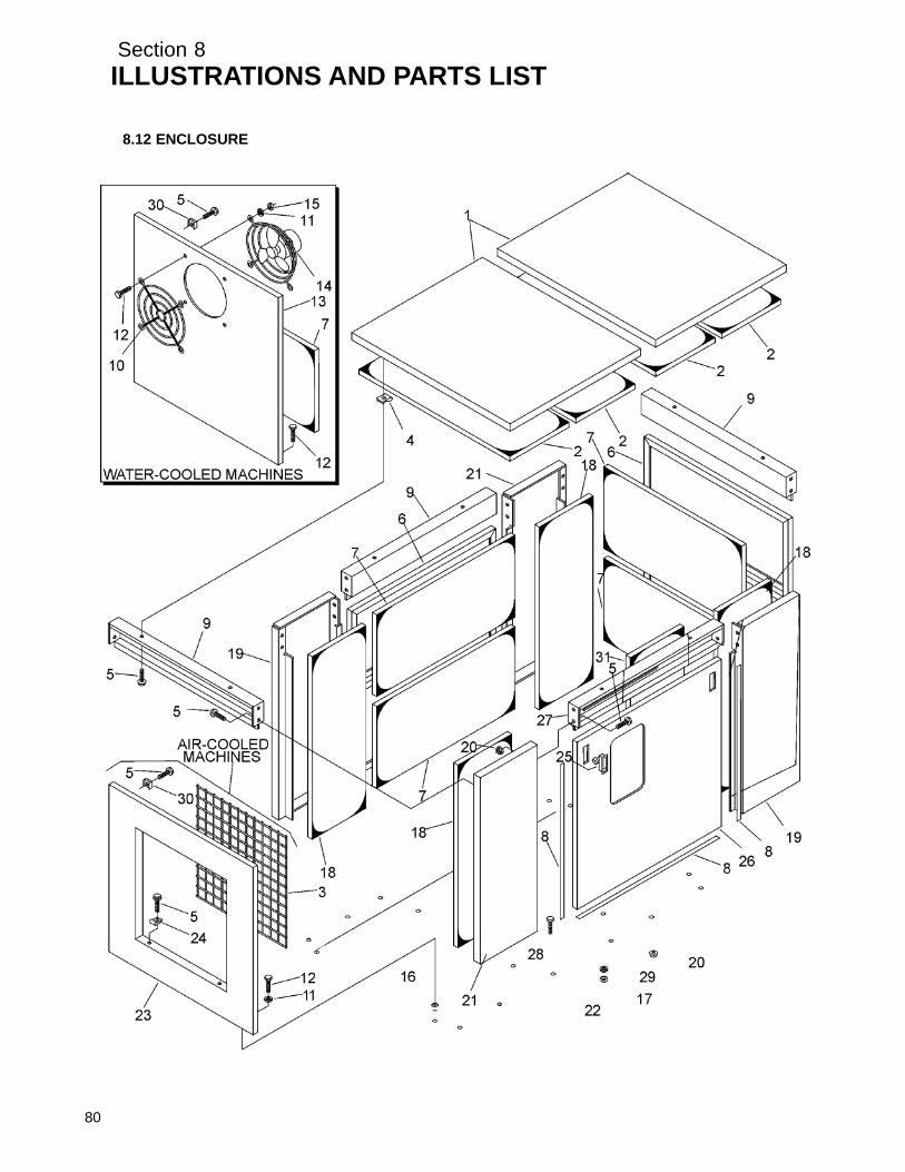
Section 8ILLUSTRATIONS AND PARTS LIST
8.12 ENCLOSURE
80

Section 8ILLUSTRATIONS AND PARTS LIST
8.12 ENCLOSURE
key partnumber description number quantity
1 panel, roof ls10 250018--316 22 panel, fiberglass 5” x 35--1/2” 43 connector, tube--f 1/4”t x 1/8”p stainless steel 242095 14 nut, retainer “j” 5/16”--18 861505--140 145 screw, ser washer 5/16” x 3/4”(AC) 829705--075 40
Sscrew, ser washer 5/16” x 3/4”(WC) 829705--075 366 panel, access 014620 27 panel, fiberglass 15--1/4” x 32--1/2” 48 weatherstrip, felt 02250058--345 759 panel, enclosure center 224585 3
10 guard, fan 13” 241579 111 washer, springlock reg plated 1/4”(AC) 837804--062 8
Swasher, springlock reg plated 1/4”(WC) 837804--062 1212 capscrew, hex gr5 1/4”--20 x 1”(AC) 829104--100 8
Scapscrew, hex gr5 1/4”--20 x 1”(WC) 829104--100 1213 panel, wc end 02250043--677 114 fan, enclosure wc 241580 115 nut, hex plated 1/4”--20 825204--226 416 rivet, tubular 1/4”--20 049824 817 nut, hex plated 1/2”--13 825208--448 418 panel, fiberglass 13” x 36--1/2” 250020--059 419 panel, enclosure – right hand corner 224583 220 nut, hex ser washer 5/16”--18 plated (AC) 825305--283 28
Snut, hex ser washer 5/16”--18 plated (WC) 825305--283 2421 panel, enclosure--left hand corner 224584 222 frame, enclosure--sub 014790 123 panel, cooler end (AC) 02250105--122 124 clamp, wire 043194 425 latch, door black 02250094--632 426 panel, access front 02250105--123 127 panel, enclosure instrument access(e/m dc) 02250104--191 1
Spanel, enclosure center(supervisor) 224585 128 capscrew, hex gr5 pltd 1/2”--13 x 1--1/2” 829108--150 429 washer, springlock reg plated 1/2” 837808--125 430 nut, retainer 5/16”--18 861405--092 431 panel, fiberglass 250034--038 1
PLEASE NOTE: WHEN ORDERING PARTS, INDICATE SERIAL NUMBER OF COMPRESSOR
81
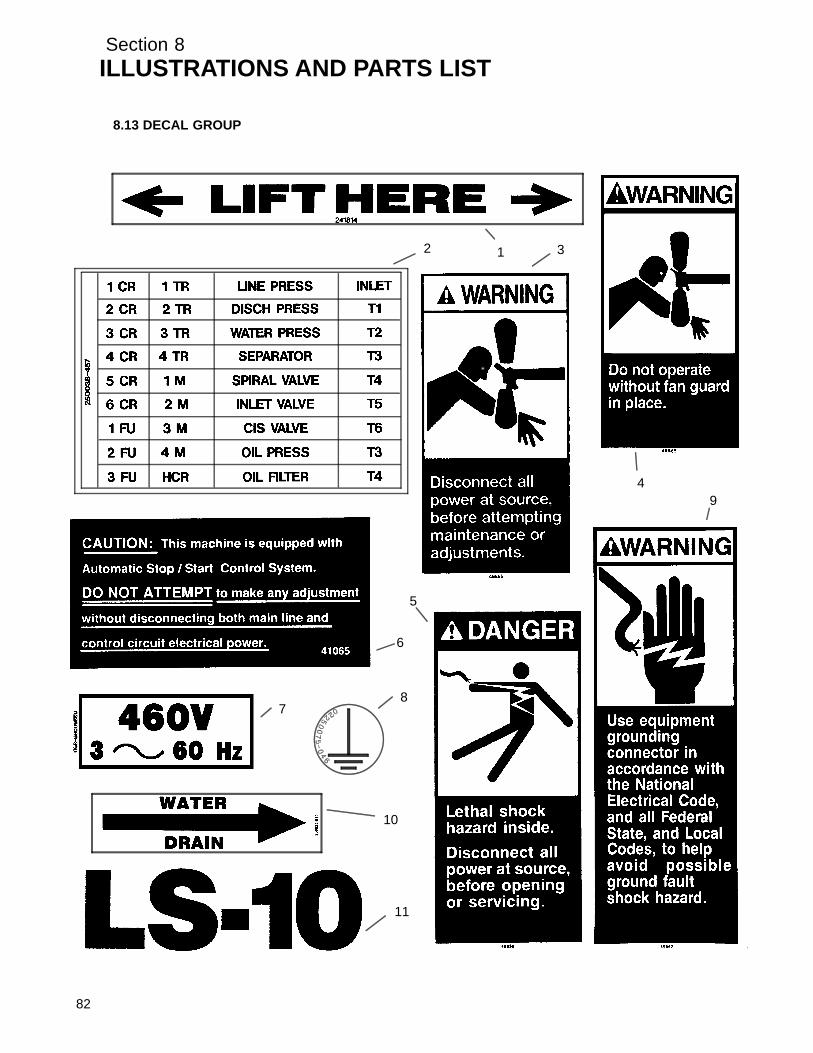
Section 8ILLUSTRATIONS AND PARTS LIST
8.13 DECAL GROUP
12 3
4
5
6
78
9
10
11
82

Section 8ILLUSTRATIONS AND PARTS LIST
8.13 DECAL GROUP
key partnumber description number quantity
1 decal, fork lifting 241814 42 decal, electrical component 250038--457 13 sign, warning sever fan 049855 24 sign, warning sever fan port 049965 15 sign, danger electrocution 049850 16 decal, warning auto start 041065 17 decal, 460 voltage international (I) 02250069--399 18 decal, earth ground 02250075--046 1
Sdecal, protective earth ground (not shown) 02250075--045 1Sdecal, PE designation (not shown) 02250075--540 1
9 decal, warning ground fault 049852 110 decal, water drain 250022--810 111 decal, LS--10 2” high 02250060--916 1
(Continued on page 85)
(I) Compressor voltage may vary. Consult Factory with machine serial number.
PLEASE NOTE: WHEN ORDERING PARTS, INDICATE SERIAL NUMBER OF COMPRESSOR
83

Section 8ILLUSTRATIONS AND PARTS LIST
8.13 DECAL GROUP
12
13
1415
16
17
18
19
20
!
21
22
ADD
FULL
84

Section 8ILLUSTRATIONS AND PARTS LIST
8.13 DECAL GROUP (CONTINUED)
key partnumber description number quantity
12 sign, warning “food grade” lube 250003--144 113 sign, danger air breathing 250027--935 114 sign, warning compressor fluid fill cap 049685 115 decal, warning auto start 250017--903 116 decal, fluid Sullube 02250069--389 1
Sdecal, fluid 24KT (not shown) 02250069--395 1Sdecal, fluid SRF 1/4000 (not shown) 02250069--391 1
17 decal, warning mixing fluids 02250110--891 118 decal, gauge fluid level 250020--730 119 decal, danger high voltage 042218 120 decal, “water in” 250019--107 121 decal, “water out” 250019--108 122 decal, water inlet/outlet 049873 1
(Continued on page 87)
PLEASE NOTE: WHEN ORDERING PARTS, INDICATE SERIAL NUMBER OF COMPRESSOR
85
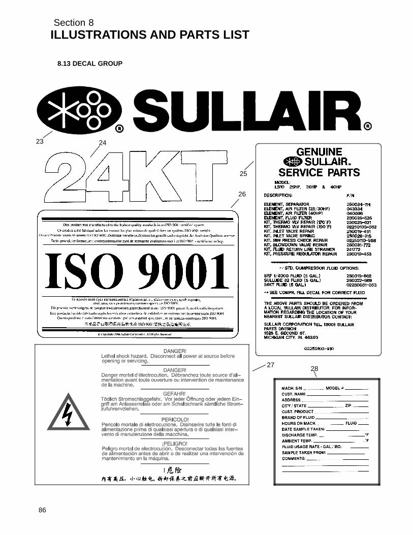
Section 8ILLUSTRATIONS AND PARTS LIST
8.13 DECAL GROUP
23 24
25
26
27 28
86

Section 8ILLUSTRATIONS AND PARTS LIST
8.13 DECAL GROUP (CONTINUED)
key partnumber description number quantity
23 decal, Sullair 02250059--054 224 decal, 24 KT 02250061--016 125 decal, maintenance kit LS--10 02250103--910 126 decal, ISO 9001 02250057--624 127 decal, electrocution hazard international 02250077--472 128 decal, fluid sample 250022--675 132 plate, rotation arrow (not shown) 02250057--737 133 decal, instrument pnl
universal (not shown) 02250051--301 134 decal, instument pnl
universal (not shown) 02250051--303 135 decal, instrument pnl
universal--dual cntrl (not shown) 02250059--410 136 decal, instrument pnl 10 Series
universal (see Section 8.9) 02250060--034 137 label, Supervisor II info univ dlx (not shown) 02250071--152 1
PLEASE NOTE: WHEN ORDERING PARTS, INDICATE SERIAL NUMBER OF COMPRESSOR
87
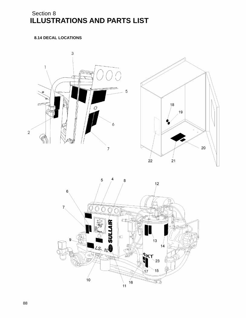
Section 8ILLUSTRATIONS AND PARTS LIST
8.14 DECAL LOCATIONS
88

Section 8ILLUSTRATIONS AND PARTS LIST
8.14 DECAL LOCATIONS (CONTINUED)
key partnumber description number quantity
1 sign, warning sever fan 049855 22 sign, warning sever fan port 049965 13 decal, instument pnl universal 02250051--303 14 decal, instrument pnl universal 02250051--301 15 decal, electrocution hazard international 02250077--472 16 sign, danger electrocution 049850 17 decal, warning auto start 250017--903 18 decal, warning auto start 041065 19 decal, ISO 9001 02250057--624 1
10 decal, LS--10 2” high 02250060--916 111 decal, Sullair 02250059--054 212 sign, warning “food grade” lube 250003--144 113 sign, danger air breathing 250027--935 114 decal, maintenance kit LS--10 02250103--910 115 sign, warning compressor fluid fill cap 049685 116 decal, warning mixing fluids 02250110--891 117 decal, fluid Sullube 02250069--389 1
Sdecal, fluid 24KT 02250069--395 1Sdecal, fluid SRF 1/4000 02250069--391 1
18 decal, protective earth ground 02250075--045 119 decal, PE designation 02250075--540 120 decal, danger hi voltage 042218 121 decal, 460 voltage international (I) 02250069--399 122 decal, warning auto start (II) 250017--903 123 decal, 24 KT (III) 02250061--016 1
(Continued on page 89)
(I) Compressor voltage may vary. Consult Factory with machine serial number.(II) Decal is located where shown, but on the inside of the control box (left side).(III) Decal used when applicable with 24KT fluid only.
PLEASE NOTE: WHEN ORDERING PARTS, INDICATE SERIAL NUMBER OF COMPRESSOR
89

Section 8ILLUSTRATIONS AND PARTS LIST
8.14 DECAL LOCATIONS
40 HP Model25---30 HP Model24
25
26
90

Section 8ILLUSTRATIONS AND PARTS LIST
8.14 DECAL LOCATIONS (CONTINUED)
key partnumber description number quantity
24 sign, warning sever fan 049855 225 decal, water drain 250022--810 126 sign, warning sever fan port 049965 1
PLEASE NOTE: WHEN ORDERING PARTS, INDICATE SERIAL NUMBER OF COMPRESSOR
91

Section 8ILLUSTRATIONS AND PARTS LIST
92
8.15 DECAL LOCATIONS- ENCLOSURE

Section 8ILLUSTRATIONS AND PARTS LIST
8.15 DECAL LOCATIONS- ENCLOSURE
key partnumber description number quantity
1 decal, LS--10 2” high 02250060--916 12 decal, fork lifting 241814 23 decal, Sullair 02250059--054 14 sign, warning “food grade” lube 250003--144 15 sign, danger air breathing 250027--935 16 decal, water drain 250022--810 1
PLEASE NOTE: WHEN ORDERING PARTS, INDICATE SERIAL NUMBER OF COMPRESSOR
93
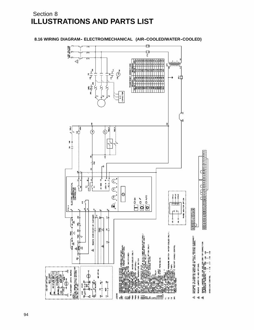
Section 8ILLUSTRATIONS AND PARTS LIST
94
8.16 WIRING DIAGRAM-- ELECTRO/MECHANICAL (AIR--COOLED/WATER--COOLED)

Section 8ILLUSTRATIONS AND PARTS LIST
8.17 WIRING DIAGRAM-- SUPERVISOR II DELUXE (AIR--COOLED/WATER--COOLED)
95

Section 8ILLUSTRATIONS AND PARTS LIST
96
8.18 WIRING DIAGRAM-- WYE--DELTA ELECTRO-MECHANICAL (AIR--COOLED/WATER--COOLED)

Section 8ILLUSTRATIONS AND PARTS LIST
8.19 WIRING DIAGRAM-- WYE--DELTA SUPERVISOR II DELUXE (AIR--COOLED/WATER--COOLED)
97

Section 8ILLUSTRATIONS AND PARTS LIST
98
8.20 WIRING DIAGRAM-- WYE--DELTA ELECTRO--MECHANICAL (EUROPEAN) (AIR--COOLED/WA-TER--COOLED)

Section 8ILLUSTRATIONS AND PARTS LIST
8.21 WIRING DIAGRAM-- WYE--DELTA SUPERVISOR II (EUROPEAN) (AIR--COOLED/WATER--COOLED)
99

WORLDWIDE SALES AND SERVICE
R
SULLAIR EUROPE, S.A.
SULLAIR CORPORATION3700 East Michigan Boulevard
Michigan City, Indiana 46360 U.S.A.Telephone: 1--219--879--5451
Fax: (219) 874--1273Fax: (219) 874--1835 (Parts)
Fax: (219) 874--1288 (Service)
SULLAIR ASIA, LTD.Sullair Road, No. 1Chiwan, Shekou
Shenzhen, Guangdong PRV.PRC POST CODE 518068Telephone: 755--6851686
Fax: 755--6853473
Zone Des Granges BP 8242602 Montbrison Cedex, France
Telephone: 33--477968470Fax: 33--477968499
Printed in U.S.A.
Specifications Subject ToChange Without Prior Notice
E99ep