Embed Size (px)
Citation preview

Induced Drag and High-Speed Aerodynamics!
Robert Stengel, Aircraft Flight Dynamics, MAE 331, 2016
Copyright 2016 by Robert Stengel. All rights reserved. For educational use only.http://www.princeton.edu/~stengel/MAE331.html
http://www.princeton.edu/~stengel/FlightDynamics.html
Learning Objectives•! Understand drag-due-to-lift and effects of
wing planform •! Recognize effect of angle of attack on lift
and drag coefficients •! How to estimate Mach number (i.e., air
compressibility) effects on aerodynamics•! Be able to use Newtonian approximation to
estimate lift and drag
Reading:!Flight Dynamics !
Aerodynamic Coefficients, 85-96!Airplane Stability and Control!
Chapter 1!
1
Early Developments in Stability and Control!
Chapter 1, Airplane Stability and Control, Abzug and Larrabee!
•! What are the principal subject and scope of the chapter?!
•! What technical ideas are needed to understand the chapter?!
•! During what time period did the events covered in the chapter take place?!
•! What are the three main "takeaway" points or conclusions from the reading?!
•! What are the three most surprising or remarkable facts that you found in the reading?!
2

Review Questions!!! What is the relationship between circulation and
aerodynamic lift?!!! What causes aerodynamic “stall”?!!! What is the difference between leading-edge and
trailing-edge flap effects?!!! Linear angle of attack variation causes __ lift
variation…!!! Linear angle of attack variation causes __ drag
variation…!!! How does wing aspect ratio affect the lift slope?!!! What is control flap “carryover effect”?!
3
Induced Drag!
4

Aerodynamic Drag
Drag = CD12!V 2S " CD0
+ #CL2( ) 12 !V
2S
" CD0+ # CLo
+CL$$( )2%
&'()*12!V 2S
5
Induced Drag of a Wing, !CL2
!! Lift produces downwash (angle proportional to lift)!! Downwash rotates local velocity vector CW in figure!! Lift is perpendicular to velocity vector!! Axial component of rotated lift induces drag
6
!! But what is the proportionality factor, !?
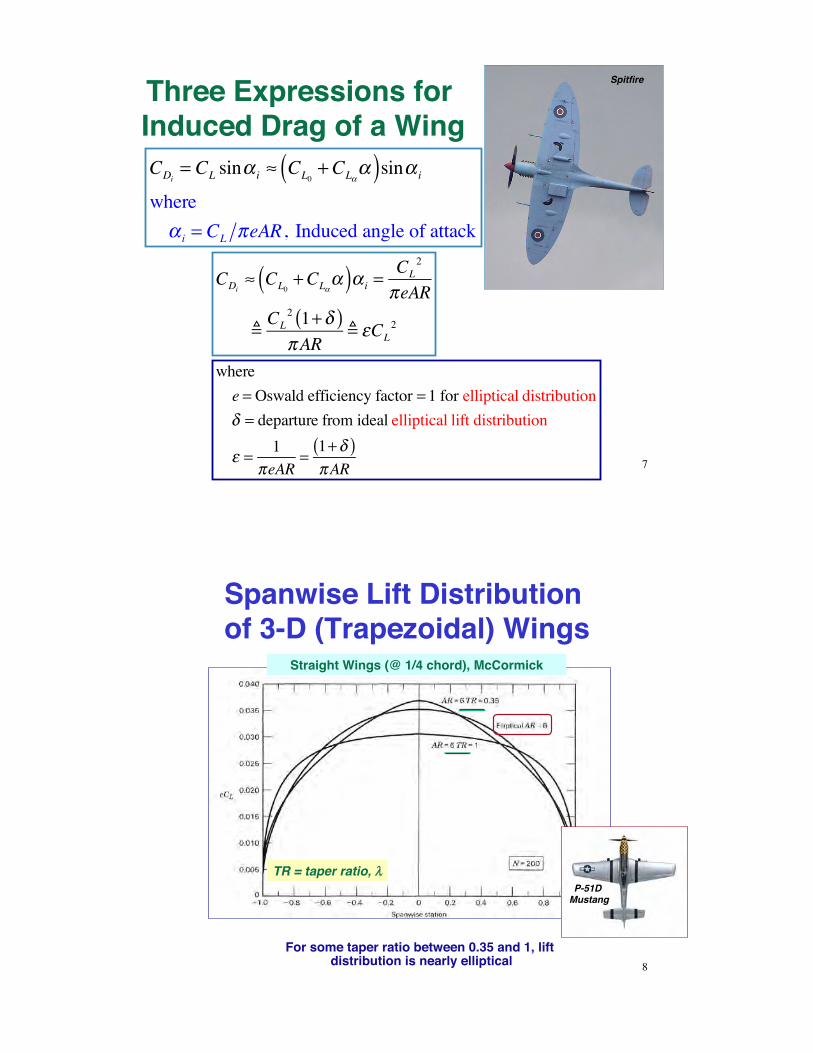
Three Expressions for Induced Drag of a WingCDi
= CL sin! i " CL0+CL!
!( )sin! i
where! i = CL #eAR, Induced angle of attack
CDi! CL0
+CL""( )" i =
CL2
#eAR
!CL
2 1+$( )#AR
! %CL2
Spitfire
7
wheree = Oswald efficiency factor = 1 for elliptical distribution! = departure from ideal elliptical lift distribution
" = 1#eAR
=1+!( )#AR
Spanwise Lift Distribution of 3-D (Trapezoidal) Wings
Straight Wings (@ 1/4 chord), McCormick
TR = taper ratio, !!
For some taper ratio between 0.35 and 1, lift distribution is nearly elliptical 8
P-51D Mustang

Induced Drag Factor, "
•! Graph for " (McCormick, p. 172)
Lower AR
CDi=CL2 1+ !( )"AR
9
Oswald Efficiency Factor, e
Empirical approximations for e
e !1.1CL"
RCL"+ (1# R)$AR
CDi=
CL2
!eAR
10
! = AR "cos#LE
R = 0.0004! 3 $ 0.008! 2 + 0.05! + 0.86
Pamadi
e !1.78 1" 0.045AR0.68( )" 0.64 [Straight wing]
Raymer
e ! 4.61 1" 0.045AR0.68( ) cos#LE( )0.15 " 3.1 [Swept wing]

Maximum Lift-to-Drag RatioMaximize L/D by proper choice of CL
LD
= CL
CD
= CL
CDo+ !CL
2!(L /D)!CL
= 0
!(L /D)!CL
= 0 =CDo
+ "CL2( )#CL 2"CL( )
CDo+ "CL
2( )2=
CDo# "CL
2( )CDo
+ "CL2( )2
CL( ) L/D( )max=
CDo
!11
L /D( )max =1
2 !CDo
Large Angle Variations in Subsonic Drag Coefficient (0° < # < 90°)
All wing drag coefficients converge to Newtonian-like values at very high angle of attack
Low-AR wing has less drag than high-AR wing at given # 12
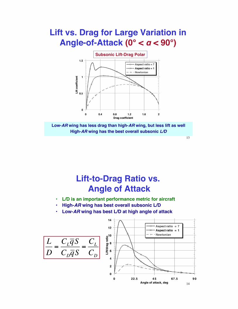
Lift vs. Drag for Large Variation in Angle-of-Attack (0° < # < 90°)
Subsonic Lift-Drag Polar
Low-AR wing has less drag than high-AR wing, but less lift as wellHigh-AR wing has the best overall subsonic L/D
13
Lift-to-Drag Ratio vs. Angle of Attack
•! L/D is an important performance metric for aircraft•! High-AR wing has best overall subsonic L/D•! Low-AR wing has best L/D at high angle of attack
LD
=CLq SCDq S
=CL
CD
14

Conversions from Propellers to JetsDouglas XB-43
Douglas XB-42 Mixmaster
Convair B-36 Convair YB-60
Northrop YB-35
Northrop XB-49
!!iiss""rriiccaall FFaacc""iidd
15
Jets at an Awkward Age•! Performance of the first jet aircraft
outstripped stability and control technology–! Lacked satisfactory actuators,
sensors, and control electronics–! Transistor: 1947, integrated circuit:
1958•! Dramatic dynamic variations over
larger flight envelope–! Control mechanisms designed to
lighten pilot loads were subject to instability
•! Reluctance of designers to embrace change, fearing decreased reliability, increased cost, and higher weight
North American B-45
Lockheed P-80
Douglas F3D
Convair XP-81
!!iiss""rriiccaall FFaacc""iidd
16

Mach Number Effects!
Ernst Mach1838-1916
Mach Number = True AirspeedSpeed of Sound
Supersonic Bullet, 1888
17
Drag Due to Pressure Differential
CDbase= Cpressurebase
SbaseS ! 0.029
CfrictionSwetSbase
SbaseS
M <1( ) Hoerner[ ]
< 2" M 2
SbaseS
#$%
&'( M > 2, " = specific heat ratio( )
“The Sonic Barrier”
Blunt base pressure drag
CDwave!CDincompressible
1"M 2M <1( )
!CDcompressible
M 2 "1M >1( )
!CDM! 2
M 2 "1M >1( )
Prandtl factor
18

Shock Waves inSupersonic Flow
•! Drag rises due to pressure increase across a shock wave
•! Subsonic flow–! Local airspeed is less than sonic
(i.e., speed of sound) everywhere
•! Transonic flow–! Airspeed is less than sonic at
some points, greater than sonic elsewhere
•! Supersonic flow–! Local airspeed is greater than
sonic virtually everywhere
•! Critical Mach number–! Mach number at which local
flow first becomes sonic–! Onset of drag-divergence–! Mcrit ~ 0.7 to 0.85
Air Compressibility Effect
19
Effect of Chord Thickness on Wing
Pressure Drag
•! Thinner chord sections lead to higher Mcrit, or drag-divergence Mach number
Lockheed P-38Lockheed F-104
20

Air Compressibility Effect on Wing Drag
Subsonic
SupersonicTransonic
Incompressible
Sonic Boomshttp://www.youtube.com/watch?v=gWGLAAYdbbc
21
Pressure Drag on Wing Depends on Sweep Angle
Mcritswept=Mcritunswept
cos!
Talay, NASA SP-367 22

From Straight to Swept Wings•! Straight-wing models were redesigned with swept wings to
reduce compressibility effects on drag and increase speed•! Dramatic change in stability, control, and flying qualitiesNorth American FJ-1 and
FJ-4 FuryRepublic F-84B Thunderbird and
F-84F ThunderstreakGrumman F9F-2 Panther and
F9F-6 Cougar
!!iiss""rriiccaall FFaacc""iidd
23
Supercritical Wing
•! Richard Whitcomb s supercritical airfoil –! Wing upper surface flattened to increase Mcrit–! Wing thickness can be restored
•! Important for structural efficiency, fuel storage, etc.
Pressure Distribution on Supercritical Airfoil ~ Section Lift
(–)
(+)
NASA Supercritical Wing F-8
Airbus A320
24

Subsonic Air Compressibility and Sweep Effects on 3-D Wing Lift Slope
•! Subsonic 3-D wing, with sweep effect
CL!=
"AR
1+ 1+ AR2cos#1 4
$
%&&
'
())
2
1*M 2 cos#1 4( )+
,
---
.
/
000
"1 4 = sweep angle of quarter chord25
Subsonic Air Compressibility Effects on 3-D Wing Lift Slope•! Subsonic 3-D wing, sweep = 0
plot(pi A / (1+sqrt(1 + ((A / 2)^2) (1 - M^2))), A=1 to 20, M = 0 to 0.9)
26
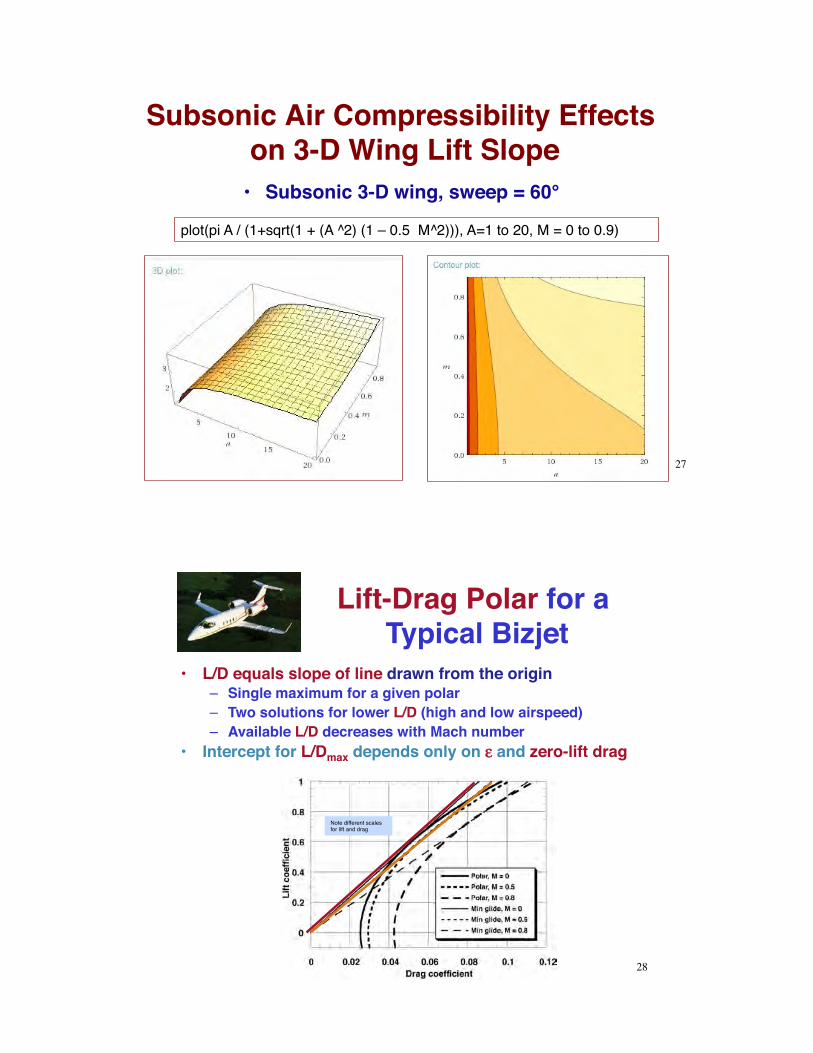
Subsonic Air Compressibility Effects on 3-D Wing Lift Slope•! Subsonic 3-D wing, sweep = 60°
plot(pi A / (1+sqrt(1 + (A ^2) (1 – 0.5 M^2))), A=1 to 20, M = 0 to 0.9)
27
Lift-Drag Polar for a Typical Bizjet
•! L/D equals slope of line drawn from the origin–! Single maximum for a given polar–! Two solutions for lower L/D (high and low airspeed)–! Available L/D decreases with Mach number
•! Intercept for L/Dmax depends only on !! and zero-lift drag
Note different scales for lift and drag
28
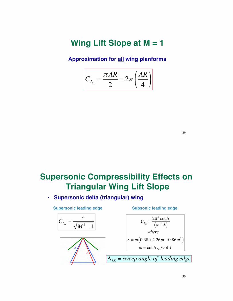
Wing Lift Slope at M = 1Approximation for all wing planforms
CL!="AR2
= 2" AR4
#
$%
&
'(
29
Supersonic Compressibility Effects on Triangular Wing Lift Slope
•! Supersonic delta (triangular) wing
CL!=
4M 2 "1
Supersonic leading edge
CL!= 2"
2 cot#" + $( )
where
$ = m 0.38 + 2.26m % 0.86m2( )m = cot#LE cot&
Subsonic leading edge
"LE = sweep angle of leading edge
30

Supersonic Effects on Arbitrary Wing and Wing-Body Lift Slope
•! Impinging shock waves•! Discrete areas with differing M and
local pressure coefficients, cp•! Areas change with #•! No simple equations for lift slope
Schlicting & Truckenbrodt, 197931
Fighter Jets of the 1950s: “Century Series”•! Emphasis on supersonic speed
Republic F-105
Lockheed F-104
Convair F-102
McDonnell F-101North American F-100
!!iiss""rriiccaall FFaacc""iidd
32

What Happened to the F-103?
Republic F-105(833 built)
!!iiss""rriiccaall FFaacc""iidd
Republic XF-103
33
Transonic Drag Rise and the Area Rule•! Richard Whitcomb (NASA Langley) and Wallace Hayes (Princeton)•! YF-102A (left) could not break the speed of sound in level flight;
F-102A (right) could
34
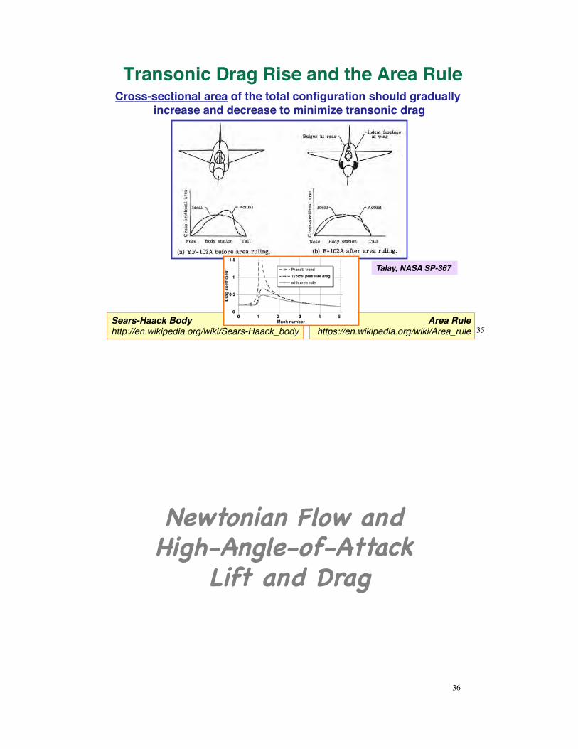
Area Rulehttps://en.wikipedia.org/wiki/Area_rule
Transonic Drag Rise and the Area Rule
Talay, NASA SP-367
Cross-sectional area of the total configuration should gradually increase and decrease to minimize transonic drag
Sears-Haack Bodyhttp://en.wikipedia.org/wiki/Sears-Haack_body 35
Newtonian Flow and High-Angle-of-Attack
Lift and Drag!
36

Newtonian Flow
•! No circulation•! Cookie-cutter flow•! Equal pressure
across bottom of the flat plate
•! Flow brought to a halt at the surface
Normal Force =
Mass flow rateUnit area
!
"#
$
%& Change in velocity( ) Projected Area( ) Angle between plate and velocity( )
37
Newtonian FlowN = !V( ) V " 0( ) S sin#( ) sin#( )= !V 2( ) S sin2#( )
Lift = N cos!
CL = 2sin2!( )cos!Drag = N sin!CD = 2sin3!
Lift and drag coefficients
38
= 2sin2!( ) 12 "V2#
$%&'( S
) CN12"V 2#
$%&'( S = CNqS
CN = 2sin2!

Newtonian Lift and Drag Coefficients
CL = 2sin2!( )cos!
CD = 2sin3!
39
Application of Newtonian Flow
•! Hypersonic flow (M ~> 5)–! Shock wave close to surface
(thin shock layer), merging with the boundary layer
–! Flow is ~ parallel to the surface–! Separated upper surface flow
Space Shuttle inSupersonic Flow
High-Angle-of-Attack Research
Vehicle (F-18)
40
•! But where does the airflow go?
•! All Mach numbers at high angle of attack–! Separated flow on upper
(leeward) surfaces Flat Plate, Re = 50,000
Next Time:!Aerodynamic Moments
(i.e., Torques)!Reading:!
Flight Dynamics !Aerodynamic Coefficients, 96-118!Airplane Dynamics and Control!
Chapter 6!
41
Learning ObjectivesExpressions for aerodynamic balance and moment
Concepts of aerodynamic center, center of pressure, and static margin
Configuration and angle-of-attack effects on pitching moment and stability
Calculate configuration and sideslip-angle effects on lateral-directional (i.e., rolling and yawing) aerodynamic moments
Tail design effects on airplane aerodynamics
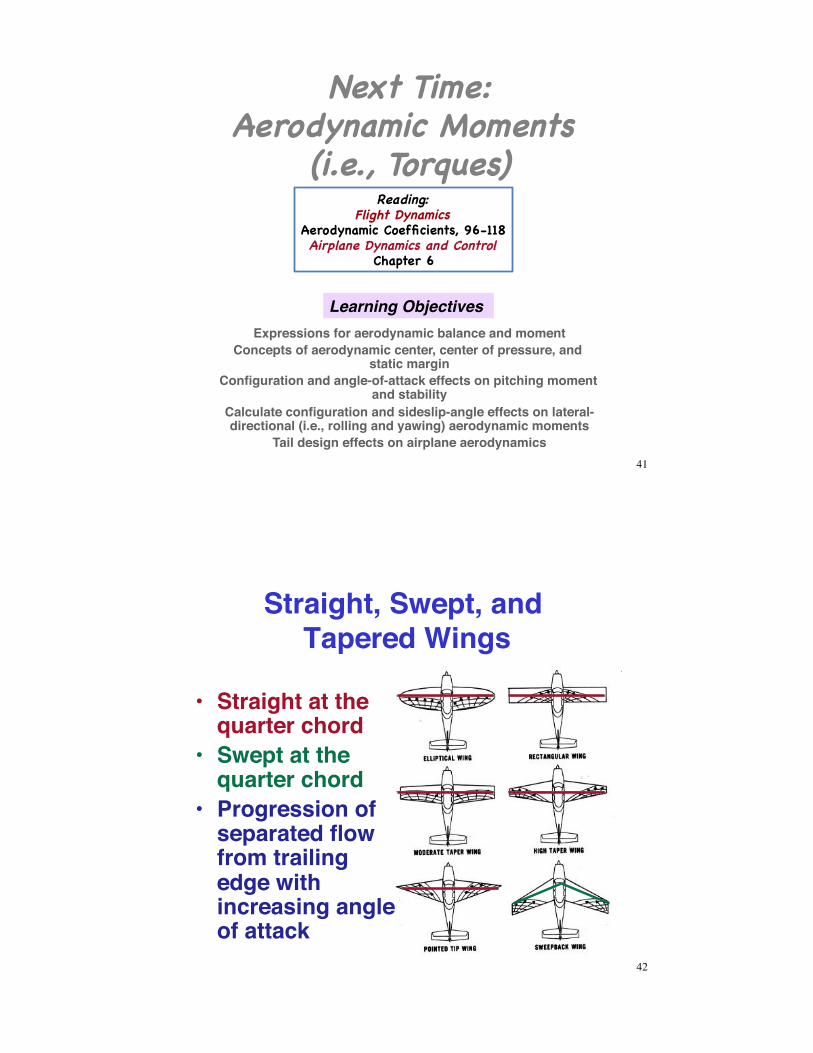
Straight, Swept, and Tapered Wings
•! Straight at the quarter chord
•! Swept at the quarter chord
•! Progression of separated flow from trailing edge with increasing angle of attack
42

Spanwise Lift Distribution of 3-D Wings
•! Wing does not have to have a geometrically elliptical planform to have a nearly elliptical lift distribution
•! Sweep moves lift distribution toward tipsStraight and Swept Wings
(NASA SP-367)
CL2!D(y)c(y)
CL3!Dc
43
Transonic Sweep Effects on 3-D Wing Lift SlopeSubsonic 3-D wing, M = 0.85
plot(pi A / (1+sqrt(1 + ((A / 2 cos(L)) ^2) (1 – cos(L) 0.85^2))), A=1 to 20, L = 0 to (pi / 3))
44

Sweep Reduces Subsonic Lift Slope
CL!=
"AR
1+ 1+ AR2cos#1 4
$
%&'
()
2
1* M 2 cos#1 4( )+
,
---
.
/
000
="AR
1+ 1+ AR2cos#1 4
$
%&'
()
2+
,
---
.
/
000
[Incompressible flow]
CL!=
2" 2 cot#LE
" + $( )where $ = m 0.38 + 2.26m % 0.86m2( )
m = cot#LE cot&#LE , & : measured from y axis
Swept Wing
Triangular Wing
45
P-51 Mustang
http://en.wikipedia.org/wiki/P-51_Mustang
Wing Span = 37 ft (9.83m)Wing Area = 235 ft (21.83m2 )Loaded Weight = 9,200 lb (3, 465 kg)Maximum Power = 1,720 hp (1,282 kW )CDo
= 0.0163AR = 5.83! = 0.5
46

P-51 Mustang Example
CL!=
"AR
1+ 1+ AR2
#$%
&'(
2)
*++
,
-..
= 4.49 per rad (wing only)
e = 0.947/ = 0.05570 = 0.0576
CDi= !CL
2 =CL2
"eAR=CL2 1+ #( )"AR
http://www.youtube.com/watch?v=WE0sr4vmZtU 47
•! Vortex generators, fences, vortilons, notched or dog-toothed wing leading edges–! Boundary layer control–! Maintain attached flow with increasing #–! Avoid tip stall
Secondary Wing Structures
McDonnell-Douglas F-4
Sukhoi Su-22
LTV F-8
48
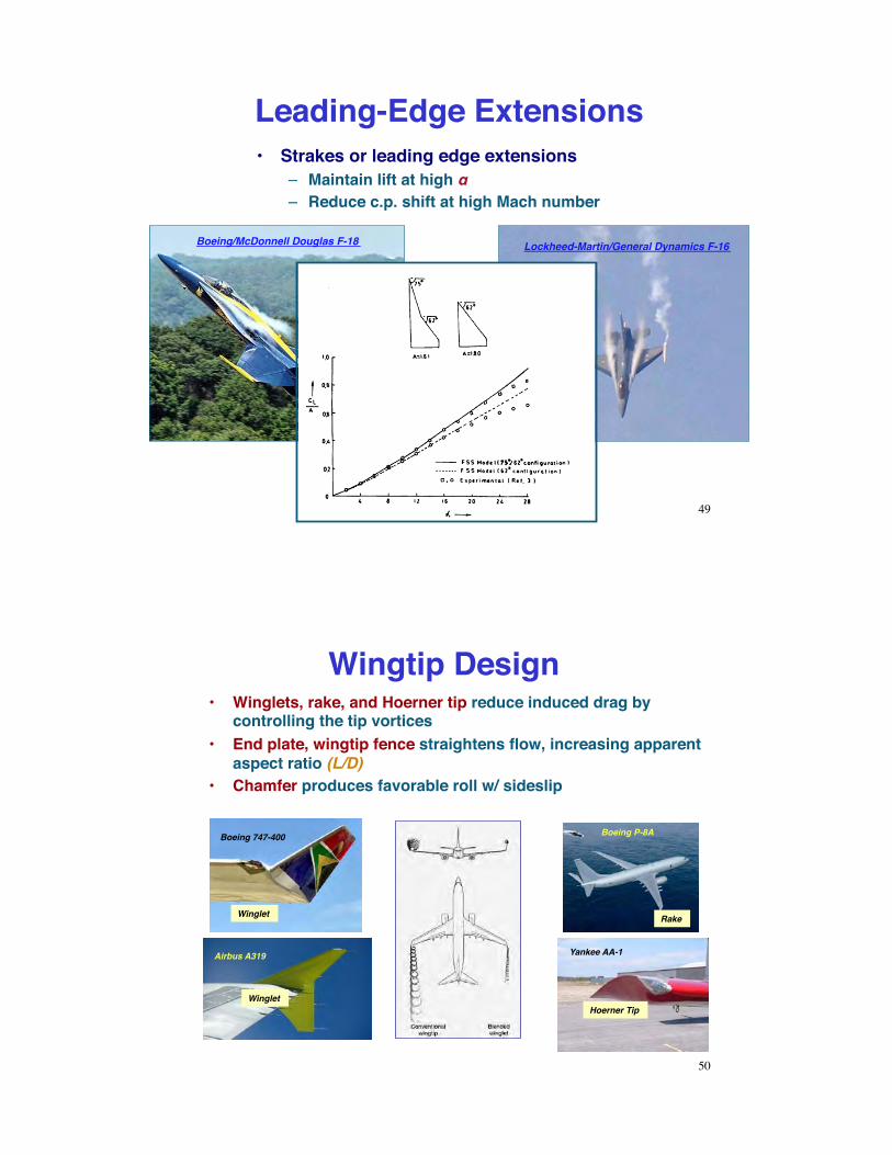
•! Strakes or leading edge extensions–! Maintain lift at high #–! Reduce c.p. shift at high Mach number
Leading-Edge Extensions
Boeing/McDonnell Douglas F-18 Lockheed-Martin/General Dynamics F-16
49
•! Winglets, rake, and Hoerner tip reduce induced drag by controlling the tip vortices
•! End plate, wingtip fence straightens flow, increasing apparent aspect ratio (L/D)
•! Chamfer produces favorable roll w/ sideslip
Wingtip Design
Yankee AA-1
Boeing 747-400 Boeing P-8A
Airbus A319
Winglet
Winglet
Rake
Hoerner Tip
50

•! Marked by noticeable, uncommanded changes in pitch, yaw, or roll and/or by a marked increase in buffet
•! Stall must be detectable•! Aircraft must pitch down when it
occurs•! Up to the stall break, ailerons and
rudder should operate properly•! Inboard stall strips to prevent tip stall
and loss of roll control before the stall•! Strakes for improved high-# flight
Design for Satisfactory Stalls
51
Low Aspect Ratio ConfigurationsNorth American A-5A Vigilante
•! Typical for supersonic aircraft Lockheed F-104 Starfighter
Mmax = 1.25hceiling = 53 kft
Mmax = 2hceiling = 52 kft
Mcruise = 1.4hcreiling= 50 kft
52

Variable Aspect Ratio ConfigurationsGeneral Dynamics F-111
North American B-1
Aerodynamic efficiency at sub- and supersonic speeds
Mcruise = 0.9Mmax = 1.25hcruise = 50 kftMmax = 2.5
hceiling = 65 kft
53
Sweep Effect on Thickness Ratio
Grumman F-14
from Asselin
54

Reconnaissance AircraftLockheed U-2 (ER-2) Lockheed SR-71 Trainer
•! Subsonic, high-altitude flight •! Supersonic, high-altitude flight
Mcruise = 3hcruise = 85 kft
Vcruise = 375 kthcruise = 70 kft
55
Supersonic Biplane•! Concept of Adolf Busemann
(1935)•! Shock wave cancellation at
one specific Mach number•! 2-D wing
•! Kazuhiro Kusunose et al , Tohoku U (PAS, 47, 2011, 53-87)•! Adjustable flaps•! Tapered, variably spaced
3-D wings•! Fuselage added
http://en.wikipedia.org/wiki/Adolf_Busemann
56

Supersonic Transport Concept
•! Rui Hu, Qiqi Wang (MIT), Antony Jameson (Stanford), AIAA-2011-1248•! Optimization of biplane aerodynamics•! Sketch of possible configuration
57