Embed Size (px)
Citation preview
Indoor Monitoring Human Movements Using Dual-Receiver Radar
Baokun Liu, Michael Jian, Zhenzhong Lu, and Rachel Chen
Ancortek Inc., Fairfax, VA, USA 22030
Abstract—A K-band experimental dual-receiver radar is used for real-time indoor monitoring human movements. In this paper, we introduce the architecture of the dual-receiver radar and its specifications for indoor monitoring. We describe its design concept, advantage, and special considerations for best indoor monitoring human movements. The basic signal processing methods and algorithms, such as range-Doppler-angle-of-arrival processing, digital beamforming, range-velocity mapping, and moving target indication are discussed. Examples of interesting experimental results for monitoring multiple people are also presented and analyzed.
Keywords—indoor monitoring, dual-receiver radar, FMCW radar, range-velocity mapping, angle-of-arrival, digital beamforming
I. INTRODUCTION
Systems for indoor monitoring human movements must locate surroundings, find positions of moving objects, and identify targets to determine which one should be tracked. The system often requires networking of multiple same or different sensors. Passive infrared sensors have been widely used in home security and surveillance [1-2], but it has limitations when obstacles block the line-of-sight of sensors. Also, the environmental condition, such as air flow and sunlight, can degrade the performance of infrared sensors. Radar has advantages over infrared sensors. It is not sensitive to environmental factors, such as day or night, hot/cold air flow, dirt or rain. Especially, radar can see through the wall or obstacles, which is important for anti-terrorism.
The basic function of radar is to measure the time of flight for calculating the distance and the Doppler frequency shift for measuring the radial velocity of a target. For indoor monitoring, another important target’s position parameter is the angle of arrival (AoA), which can be measured by the phase difference between two or more receiving antennas. The accuracy of the delay-time based methods often suffers from massive indoor multipath conditions caused by reflections or diffractions of the RF signal from the interior wall, doors or furniture in the environment.
In an indoor monitoring system, radar sensor can be used for detecting moving objects and collect their position information by continuous measurements of distances and direction angles. The data collected by a single sensor are generally ambiguous and must be resolved by a series of procedures to combine several sensor input streams. Each sensor may cover an area of interest, such as a single room or an aisle. The optimal solution may be reached by combining multiple or overlapped sensors.
Prior work in radar sensors for indoor human localization primarily used ultra-wideband (UWB) impulse radar [3-5]. While impulse UWB techniques provide high peak power and high range resolution due to the short spatial extent of the
impulse waveform, commercial use of UWB radar is restricted by the tight power restrictions imposed by the Federal Communications Commission.
The FMCW radar has advantages of simplest system configuration, easy implementation, and superior performance, and it becomes a popular radar system for short range applications such as radar altimeter and automotive radar. The radar simply mixes the received signals with the transmitted signals, such that it simplifies the process of time-delay measurement by using beat frequency measurement. The relatively lower beat frequency bandwidth significantly reduces the requirement for the high-speed data acquisition. This considerably simplifies the realization of the processing circuits and has the advantage of light-weight, compact-size, low-cost and low energy consumption.
For indoor human localization, the use of FMCW radar was studied in [6-7]. In these work, range information is obtained, but the angle of arrival is not available. The MIMO radar used in [8] and the hybrid FMCW-Interferometry radar proposed in [9] are far from real-time compact radar systems. For further investigating how to simultaneously measure the range, velocity and angle of arrival in real-time by a single radar as one node of the indoor monitoring system, we utilized our current available low-power, light-weight, and dual-receiver FMCW radar to study indoor monitoring human movements.
The paper is organized as follows. In Section II, we introduce the system design. Hardware, software, and system parameters are presented in detail. Signal processing procedures are described in Section III. Test Results are presented in Section IV. We conclude the paper in Section V.
II. SYSTEM DESIGN
A K-band (24.125 GHz) dual-receiving-channel FMCW radar (Fig. 1) is used to effectively sense human movements in high multipath indoor scenarios. It guarantees a continuous indoor monitoring with a simple, low-cost and compact design. The radar consists of a dual-receiving-channel RF module and an FPGA-based processor module. A patch antenna array with one transmitting and two receiving channels is connected to the RF-module by SMA-M to SMA-M cables. A graphical user interface provides a simple way for users to control the radar system and display maps of the range, velocity, and angle-of-arrival in real time.
A. Hardware Configuration and Description
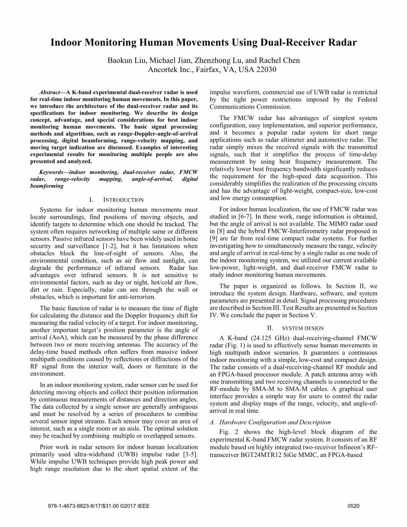
Fig. 2 shows the high-level block diagram of the experimental K-band FMCW radar system. It consists of an RF module based on highly integrated two-receiver Infineon’s RF-transceiver BGT24MTR12 SiGe MMIC, an FPGA-based
978-1-4673-8823-8/17/$31.00 ©2017 IEEE 0520
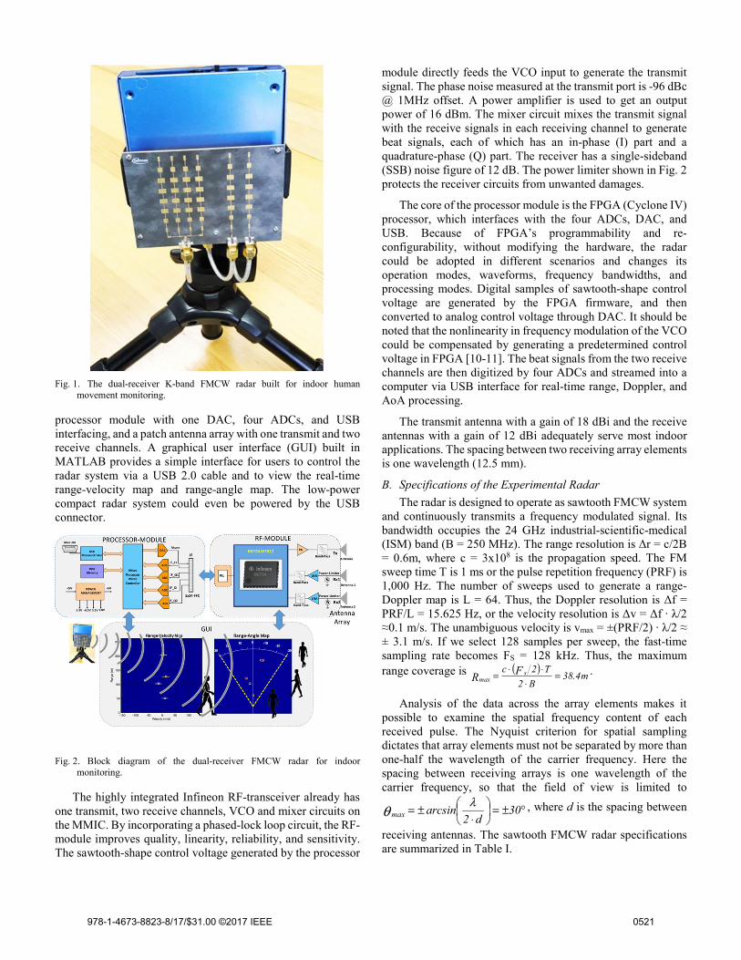
Fig. 1. The dual-receiver K-band FMCW radar built for indoor human
movement monitoring.
processor module with one DAC, four ADCs, and USB interfacing, and a patch antenna array with one transmit and two receive channels. A graphical user interface (GUI) built in MATLAB provides a simple interface for users to control the radar system via a USB 2.0 cable and to view the real-time range-velocity map and range-angle map. The low-power compact radar system could even be powered by the USB connector.
Fig. 2. Block diagram of the dual-receiver FMCW radar for indoor
monitoring.
The highly integrated Infineon RF-transceiver already has one transmit, two receive channels, VCO and mixer circuits on the MMIC. By incorporating a phased-lock loop circuit, the RF-module improves quality, linearity, reliability, and sensitivity. The sawtooth-shape control voltage generated by the processor
module directly feeds the VCO input to generate the transmit signal. The phase noise measured at the transmit port is -96 dBc @ 1MHz offset. A power amplifier is used to get an output power of 16 dBm. The mixer circuit mixes the transmit signal with the receive signals in each receiving channel to generate beat signals, each of which has an in-phase (I) part and a quadrature-phase (Q) part. The receiver has a single-sideband (SSB) noise figure of 12 dB. The power limiter shown in Fig. 2 protects the receiver circuits from unwanted damages.
The core of the processor module is the FPGA (Cyclone IV) processor, which interfaces with the four ADCs, DAC, and USB. Because of FPGA’s programmability and re-configurability, without modifying the hardware, the radar could be adopted in different scenarios and changes its operation modes, waveforms, frequency bandwidths, and processing modes. Digital samples of sawtooth-shape control voltage are generated by the FPGA firmware, and then converted to analog control voltage through DAC. It should be noted that the nonlinearity in frequency modulation of the VCO could be compensated by generating a predetermined control voltage in FPGA [10-11]. The beat signals from the two receive channels are then digitized by four ADCs and streamed into a computer via USB interface for real-time range, Doppler, and AoA processing.
The transmit antenna with a gain of 18 dBi and the receive antennas with a gain of 12 dBi adequately serve most indoor applications. The spacing between two receiving array elements is one wavelength (12.5 mm).
B. Specifications of the Experimental Radar
The radar is designed to operate as sawtooth FMCW system and continuously transmits a frequency modulated signal. Its bandwidth occupies the 24 GHz industrial-scientific-medical (ISM) band (B = 250 MHz). The range resolution is Δr = c/2B = 0.6m, where c = 3x10⁸ is the propagation speed. The FM sweep time T is 1 ms or the pulse repetition frequency (PRF) is 1,000 Hz. The number of sweeps used to generate a range-Doppler map is L = 64. Thus, the Doppler resolution is Δf = PRF/L = 15.625 Hz, or the velocity resolution is Δv = Δf · λ/2 ≈0.1 m/s. The unambiguous velocity is vmax = ±(PRF/2) · λ/2 ≈ ± 3.1 m/s. If we select 128 samples per sweep, the fast-time sampling rate becomes FS = 128 kHz. Thus, the maximum range coverage is ( )
m4.38B2
T2c FR s
max =⋅
⋅⋅= .
Analysis of the data across the array elements makes it possible to examine the spatial frequency content of each received pulse. The Nyquist criterion for spatial sampling dictates that array elements must not be separated by more than one-half the wavelength of the carrier frequency. Here the spacing between receiving arrays is one wavelength of the carrier frequency, so that the field of view is limited to
°±=
⋅±= 30
d2arcsinmax
λθ , where d is the spacing between
receiving antennas. The sawtooth FMCW radar specifications are summarized in Table I.
978-1-4673-8823-8/17/$31.00 ©2017 IEEE 0521
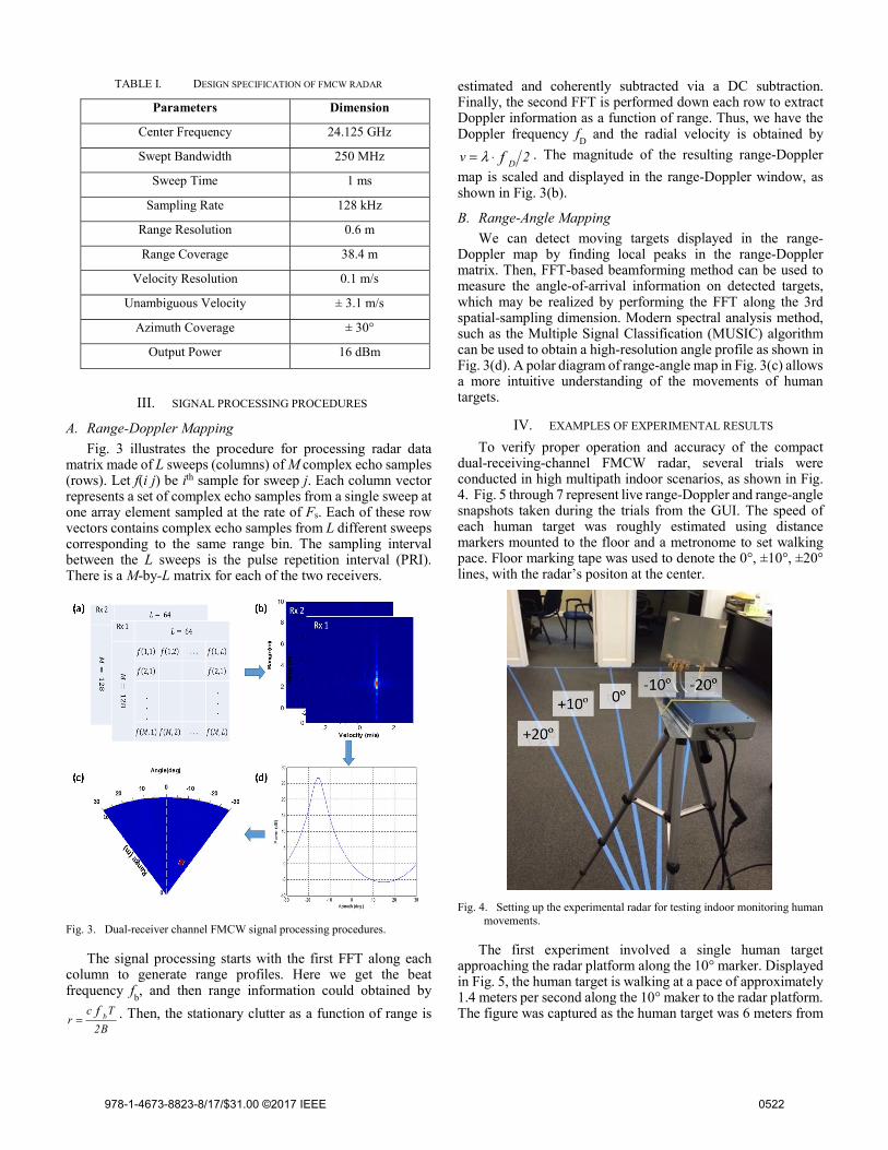
TABLE I. DESIGN SPECIFICATION OF FMCW RADAR
Parameters Dimension
Center Frequency 24.125 GHz
Swept Bandwidth 250 MHz
Sweep Time 1 ms
Sampling Rate 128 kHz
Range Resolution 0.6 m
Range Coverage 38.4 m
Velocity Resolution 0.1 m/s
Unambiguous Velocity ± 3.1 m/s
Azimuth Coverage ± 30°
Output Power 16 dBm
III. SIGNAL PROCESSING PROCEDURES
A. Range-Doppler Mapping
Fig. 3 illustrates the procedure for processing radar data matrix made of L sweeps (columns) of M complex echo samples (rows). Let f(i j) be ith sample for sweep j. Each column vector represents a set of complex echo samples from a single sweep at one array element sampled at the rate of Fs. Each of these row vectors contains complex echo samples from L different sweeps corresponding to the same range bin. The sampling interval between the L sweeps is the pulse repetition interval (PRI). There is a M-by-L matrix for each of the two receivers.
Fig. 3. Dual-receiver channel FMCW signal processing procedures.
The signal processing starts with the first FFT along each column to generate range profiles. Here we get the beat frequency f
b, and then range information could obtained by
B2
Tcr
f b= . Then, the stationary clutter as a function of range is
estimated and coherently subtracted via a DC subtraction. Finally, the second FFT is performed down each row to extract Doppler information as a function of range. Thus, we have the Doppler frequency f
D and the radial velocity is obtained by
2v f D⋅= λ . The magnitude of the resulting range-Doppler
map is scaled and displayed in the range-Doppler window, as shown in Fig. 3(b).
B. Range-Angle Mapping
We can detect moving targets displayed in the range-Doppler map by finding local peaks in the range-Doppler matrix. Then, FFT-based beamforming method can be used to measure the angle-of-arrival information on detected targets, which may be realized by performing the FFT along the 3rd spatial-sampling dimension. Modern spectral analysis method, such as the Multiple Signal Classification (MUSIC) algorithm can be used to obtain a high-resolution angle profile as shown in Fig. 3(d). A polar diagram of range-angle map in Fig. 3(c) allows a more intuitive understanding of the movements of human targets.
IV. EXAMPLES OF EXPERIMENTAL RESULTS
To verify proper operation and accuracy of the compact dual-receiving-channel FMCW radar, several trials were conducted in high multipath indoor scenarios, as shown in Fig. 4. Fig. 5 through 7 represent live range-Doppler and range-angle snapshots taken during the trials from the GUI. The speed of each human target was roughly estimated using distance markers mounted to the floor and a metronome to set walking pace. Floor marking tape was used to denote the 0°, ±10°, ±20° lines, with the radar’s positon at the center.
Fig. 4. Setting up the experimental radar for testing indoor monitoring human
movements.
The first experiment involved a single human target approaching the radar platform along the 10° marker. Displayed in Fig. 5, the human target is walking at a pace of approximately 1.4 meters per second along the 10° maker to the radar platform. The figure was captured as the human target was 6 meters from
978-1-4673-8823-8/17/$31.00 ©2017 IEEE 0522

the radar platform. The range-Doppler map and range-angle map indicate the system was operating correctly.
Fig. 5. A person is approaching the radar along the 10º marker.
In the second experiment, a single human target was measured leaving the radar platform at a slower pace of 1 meters per second along the -20°. Fig. 6 was captured as the human target was 3.5 meters from the radar platform. The target was registered at the expected location on the range-Doppler map and range-angle map.
Fig. 6. A person is walking away from the radar along the -20º marker.
The third experiment was comprised of two people walking in opposite directions in the room. The first person was walking away from the radar along the 10° marker while the second target was walking towards the radar along the -10° maker. Fig. 7 was captured while both persons were 2 meters apart. As shown in the figure, the person at 5.5 meters resulted in a weaker power return than the person at 3.5 meters.
Fig. 7. Two person are walking in opposite directions in the room.
V. CONCLUSION
The experimental study on dual-receiver FMCW radar demonstrated that the radar sensor is capable of indoor monitoring human movements through a mapping of range-velocity for detecting moving targets and through a range-angle map to track the position of human movements. This dual-receiver FMCW radar working in 24 GHz ISM band is a relatively compact, simple and inexpensive system for indoor human localization. It could serve most indoor monitoring applications, including through-the-wall human sensing, from the simple link budget analysis. We are currently evaluating and characterizing its performance for through-the-wall sensing. Future improvement is to add one more transmitting channel with a vertical offset from the first transmitting channel for capturing elevation angles in human movements.
REFERENCES [1] A. Rogalski, [History of infrared detectors], Opto-Electron. Rev. (2012)
20: 279, 2012. [2] C. Carlo, "Infrared: a key technology for security systems," Adv. in Opt.
Tech., vol. 2012, article ID 838752, 15 pages, 2012. [3] R. Fontana, "Recent system applications of short-pulse Ultra-Wide-band
(UWB) technology," IEEE Trans. Microw. Theory Tech., vol. 52, no. 9, pp.2087-2104, 2004.
[4] B. Waldmann, R. Weigel and P. Gulden, "Method for high precision local positioning radar using an ultra wideband technique," IEEE MTT-S Int. Microw. Symp. Dig., Jun. 2008, pp.117-120, 2008.
[5] T. Suzuki, K. Takizawa and T. Ikegami, "A study on human body localization while walking in an indoor environment by using UWB signal with multiple antennas," Int. Symp. on Med. Info. and Commu. Tech., pp.131-134, 2013.
[6] S. Roberto, S. Elisa, U. Laura, M. Simone, V. Roberto and M. Luca, "Accurate FMCW radar-based indoor localization system," IEEE Int. Conf. on RFID-Tech. and App., pp. 362-368, 2012.
[7] Z. Leticia, A. Naiara, J. Ainara and V. Igone, "Improving the performance of an FMCW indoor localization system by optimizing the ranging estimator," Sixth Int. Conf on Wire. and mobile Comm., pp. 596-601, 2010.
[8] R. Gierlich, J. Huttner, A. Ziroff, R. Weigel and M. Huemer, "A reconfigurable MIMO system for high-precison FMCW local positioning," IEEE Trans. Microwave Theory Tech., vol. 59, no. 12, pp.3228-3238, 2011.
[9] G. Wang, C. Gu, T. Inoue and C. Li, "A hybrid FMCW-Interferometry radar for indoor precise positioning and versatile life activity monitoring," IEEE Trans. Microwave Theory Tech., vol. 62, no. 11, pp.2812-2822, 2014.
[10] M. Pavlo, G. Shalini, K. Kihwan and P. Kari, "Short-range FMCW monopulse radar for hand-gesture sensing," Proc. RadarCon, pp.1491-1496, 2015.
[11] B. Liu and R. Chen, "Software-defined radar and waveforms for studying micro-Doppler signatures," Proc. SPIE 9077, Radar Sensor Technology XVIII, 907718, 2014.
978-1-4673-8823-8/17/$31.00 ©2017 IEEE 0523


![Index [] · Spray Slidy 11 TABLETENNISTABLES 12-16 TABLES Basic 13 Training Indoor 13 Progress Indoor 13 Challenge Indoor 13 Advance Indoor 13 Master Indoor 14 Club Indoor 14](https://img.dokumen.tips/doc/110x75/609ea898873dde113652cff3/index-spray-slidy-11-tabletennistables-12-16-tables-basic-13-training-indoor.jpg)