Embed Size (px)
Citation preview
Water-cooled: CGWN 205 – 206 – 207– 208 – 209 – 210 – 211 – 212 – 213– 214 – 215Condenserless: CCUN 205 – 206 – 207– 208 – 209 – 210 – 211 – 212 – 213– 214 – 215
Indoor liquid chiller with integratedhydraulic module
CG-PRC014-E4

CG-PRC014-E42

Contents
3CG-PRC014-E4
Introduction 4
Features and benefits 5
Options description 9
Applications consideration 10
Control 15
Selection Procedures 21
Performances 22
General data 24
Hydraulic data 31
Sound performances 35
Units schematics 37
Mechanical Specifications 44

The new Indoor AquaStream²®
chillers range equipped with Scrollcompressors combines the latesttechnologies available to offer anoptimum answer for today’s air-conditioning and process coolingapplications:- Scroll compressor technology,
with high performance, limitedmaintenance and longer life timedesign
- Latest generation of Tranecontrols, with user friendlygraphical interface and integralauto-adaptive to guaranteemaximum dependability
- High efficiency heat exchangers,allowing significant savings onoperating cost
- Integrated hydraulic packages, toshorten installation andcommissioning time.
Introduction
CG-PRC014-E44

Industry leading
performance and flexibility
for design engineers
The next generation: designed for
You
The third generation of thesuccessful indoor Scroll compressorproduct range has several benefitsover the previous design. Yoursuggestions led to theimprovements we’ve incorporated,including:- Higher full-load energy efficiency
for lower operating and life-cyclecosts
- CH530 controls, with touch-screen display and LonTalk®
capability- Less sensitivity to condenser-
water temperatures, alleviatingconcerns based on start-uptemperatures
- Lighter weight for easier and lessexpensive handling andinstallation.
Applications: Operation and control
advantages for most application
The Scroll compressor technology,with fewer moving parts, lessrotating mass and less internalfriction, associated with CH530 andAdaptive Controls™, allow theIndoor AquaStream²® range to beused in a wide variety ofapplications including:- Comfort cooling: designed for
reliability, energy efficiency, andsystem-design optimisation,whether the heat is rejected viaan open cooling tower or aclosed loop device (dry-cooler)
- Industrial process cooling:reliable operation with tightcontrol of temperatures
- Ice/thermal storage- Heat recovery- Low-temperature process
cooling.
System design and control: Greater
application flexibility for increased
savings
First-cost and operating costminimising system-design conceptsare catching on as their validity isproven through applications.These designs can provide lowerequipment costs and loweroperating costs than those possiblewith the traditional design methodsand past chiller technologies.The concepts of the IndoorAquaStream²® range include:- Heat exchangers with reduced
water pressure drops and widerwater flow/delta capability
- Thermal storage capability- Variable primary (evaporator)
chilled-water flow capability- Series evaporator and/or
condenser arrangements
The Indoor AquaStream²® range isdesigned for a wide range ofapplications and is especially suitedfor the dynamics of these systemsaving job designs. The dynamicbenefits include:- Efficient lift capability- Tight temperature control.
CH530 controls mean that theCGWN/CCUN series chillers canmaintain tight leaving-watertemperature control in almost anyapplication. These benefits fitespecially well with the systemdesign savings ideas listed above.As the compressor reaches theoperating temperatures for theapplication, the controls, make sureyou have total temperature control,even with chilled-water flow and/orload changes.
Features and benefits
5CG-PRC014-E4

Sound: Lower sound levels through
compressor and chiller design
Trane has a proven track record ofcontinuously improving the soundlevels of water chillers. With theIndoor AquaStream²® range, Tranehas designed a fully hermeticcabinet design which minimisessound radiation in theneighbourhood of the unit. Thespace around the chiller can beutilised without requirement ofadditional sound insulation. TheCCUN + outdoor condensingmodule can be an interestingalternative to an outdoor chiller:only the sound produced by thecondenser fans can be perceived inthe surrounding of the installation,the sound of compressor isattenuated by the building structure.
Minimised job time for
contractors through design
and testing
Ease of installation
- Footprint: Central to the designof any project is the operatingenvelope of the chiller. With thisin mind, Trane builds the chillersto make the most efficient use ofthe available installation space.The compact IndoorAquaStream²® range chiller is anexcellent choice for any retrofitor replacement job. It is smallerthan most chillers it mightreplace, and easier to fit intoexisting buildings. All units fitthrough a standard single door.
- Weight: Furthermore, thedecreased weight reduces therequirements for lifting, rigging,and installation. Installation timeand effort are reduced whendealing with a significantlysmaller and lighter unit.
- Commissioning: Water cooledunits (CGWN) come from thefactory fully charged withrefrigerant and oil,condenserless version (CCUN)with holding charge. Extensivefactory testing helps ensuretrouble-free start-up, resulting inlower installation costs andfaster job completion.
Everything is in the box
Thanks to built-in components,installation is easy and you willmake considerable savings usingany available space in the technicalroom.
Only a main power supply andwater connections are necessary,the main hydraulic components canbe supplied in the “box”.
The Indoor AquaStream²® integratedhydraulic can be supplied with thefollowing components:- Evaporator pump- Evaporator strainer- Expansion tank on cooling loop- Valves- Flow switch- Pressure gauge- Relief valve- Condenser pump - Condenser strainer.
The Integrated comfort system
The water-cooled AquaStream²®
chiller, with the CH530, makes apowerful combination with theTrane Tracer Summit BuildingManagement System to becomepart of a Trane Integrated Comfortsystem (ICS). An Integrated Comfortsystem is a building comfort systemcomposed of Trane HVACequipment, integral unit controllers,and building management. It is alldesigned and commissioned withTrane application expertise toprovide comfort, efficiency, andreliability, as well as single-sourcewarranty and service. Whether youare replacing a chiller or adding oneto any centrally controlled plant, theTracer CH530 chiller controlleroffers a wide range of interfaceoptions. Its ability to communicatewith other systems using industry-standard control signals allows youto upgrade the control of yourchiller plant regardless of yourcurrent control system.
Features and benefits
CG-PRC014-E46

Single-source responsibility
A wide range of products designedfor complete compatibility areavailable with the IndoorAquaStream²® scroll chillers. Yourentire building comfort system canbe completed using componentsfrom Trane.
The added value of applications
expertise
You get a quality chiller, properlyselected and applied in a properlydesigned system. That means acomfort system that works, the firsttime!
Reduced total life cycle
operating cost for building
owner.
Energy efficiency: Reduced annual
operating expenses
The Indoor AquaStream²® chillerdesign has been optimized in orderto achieve record efficiency levels.With the CH530 chiller controlmodule, control over the chilled-water temperature is increased,simultaneously reducing annualoperating costs. IndoorAquaStream²® chillers offer superiorfull-load performance andoptimised part-load performance.
Reduced maintenance: Less time
and money every year
The only recommendedmaintenance for an IndoorAquaStream²® chiller is an annualoil analysis. The hermetic designallows the compressor to be drivenby a zero-maintenance motor.Strainers upstream the evaporatorand condenser enhance the lifetimeof heat exchangers. The AdaptiveControl™ microprocessor also helpsreduce unnecessary maintenanceby monitoring, protecting, andtaking corrective action so that thechiller stays on-line when you needit the most. Service calls fornuisance trip-outs are virtuallyeliminated.
Reliability
Trane has designed the IndoorAquaStream²® chiller range to be aleader in reliability for allapplications:- Simple design with 64 percent
fewer parts than equal capacityreciprocating compressor.
- Advanced microelectronicsprotect both compressor andmotor from typical electrical faultconditions.
- Scroll compressors have lessthan a third the torque variationsof a reciprocating compressor.
- Years of laboratory testing haveoptimised compressor andchiller systems reliability.
- Water-cooled scroll chillers arefactory tested.
Comfort cooling: designed for
reliability, energy efficiency, and
system design optimisation
Most comfort-cooling applicationsconsider reliability and energyefficiency above all else in thedesign requirements. With provenreliability and high chiller efficiency,the Indoor AquaStream²® chillersare perfectly suited for theseapplications.
Industrial process cooling / Low
temperature process: Reliable
operation with tight control of
temperatures
The Trane Indoor AquaStream²®
chillers have the proven reliabilityrequired to keep the processrunning, eliminating concerns forchiller and resulting processdowntime. The chiller matchessystem requirements and rapidlyadjusts to match the changes seenby most processes.
Features and benefits
7CG-PRC014-E4

Ice / thermal storage
The Trane Indoor AquaStream²®
chillers can be used in partial or fullthermal-storage applicationsbecause of their excellentcompressor lift (operatingtemperature range) capability. Highreliability and low maintenancemeans thermal storage applicationsare possible without a full-timeoperation/maintenance staff, andTrane Integrated Comfort SystemControls can notify a computer orpager of any system issues.
Heat recovery
The Trane Indoor AquaStream²®
chillers compressor lift capabilitiesalso play well in heat recovery, orjust high-temperature condenserapplications. Building energy savinginitiatives such as using condenserwater for reheat (dehumidification),preheating boiler water, andproviding domestic hot water arecompatible with its temperaturecapabilities.
Easy serviceability
Trane Indoor AquaStream²® chillersare designed with service personnelin mind. All major components arereplaceable without complete unitdisassembly. Plus, CH530 providesdiagnostic capability to aid servicepersonnel in analysing problems.Therefore, in case a problem doesoccur, the chiller can be up andrunning in a shorter period of time.
Features and benefits
CG-PRC014-E48

Evaporator hydraulic module
Versions available:• No hydraulic control• With pump contactors to control
a remote pump (single or dual)• With pump integrated hydraulic
module, single or dual pump,low or high pressure head
Hydraulic module contents:
• Single or dual pump• Expansion vessel• Water pressure relief valve set to
4 bar• Water strainer easily removable
to allow quick cleaning.• Drainage valve• Pressure ports for gauge
connection• Water pressure gauge• Condensate collection and
drainage (below pump)• Pump winter freeze protection
down to -18°C (the pump isactivated under an ambienttemperature setting)
Condenser hydraulic module
Versions available:• No hydraulic control• With pump contactors to control
a remote pump (single or dual)• With pump integrated hydraulic
module:- 180 kW - 350 kW: 2 single
pumps in parallel to adjustcondenser waterflow as afunction of unit capacity, low orhigh pressure head
- 350 kW - 500 kW: Dual pump,low or high pressure head.
• With pump integrated hydraulicmodule and variable speeddrives:- 180 kW - 350 kW: same pumps
with separate variable speeddrive
- 350 kW - 500 kW: specific pumpwith integrated variable speeddrive
Hydraulic module contents:
• Two pumps in parallel : 180 kW - 350 kW (Variable speeddrive available as option)
• One dual pump: 350 kW - 500 kW (Variable speed driveavailable as option)
• Water strainer easily removableto allow quick cleaning.
• Drainage valve• Pressure ports for gauge
connection• Pump winter freeze protection
down to -18°C (the pump isactivated under an ambienttemperature setting)
Hot water control
This option allows the control of theunit capacity based on the leavingcondenser-water temperature topermit heat recovery.
Phase protection device
Inhibits operation of chiller in caseof phase reversal
Soft starter
To reduce starting current duringcompressor start
Setpoint and temperature offset
and display card
Allows to offset chilled watersetpoint temperature based oneither outside air, chilled waterreturn or zone temperature andprovides inlet/outlet condenserwater temperature information.
High Efficiency Option
(Only for 180-350 kW range)
This option provides oversized heatexchangers to allow the unit to bemore energy efficient.
Ice Making
The unit controls are factory set tohandle ice making for thermalstorage applications.
Communication Interface
Permits bi-directionalcommunication to the TraneIntegrated Comfort™ system andprovides the LonMark® chillerprofile input/outputs for use with ageneric BAS (Building AutomationSystem)
Low Noise Version
The unit is equipped with acompressor sound attenuatingenclosure.
Pressure Gauges
A set of two pressure gauges perrefrigerant circuit, one for lowpressure and one for high pressure.
Flange Connection Kit
Provides a kit that includes a set oftwo pipe stubs and flangecouplings.
Options description
9CG-PRC014-E4

Optimum performance of CGWNand CCUN units will be achievedonly if proper application guidelinesare followed.
Where the application varies fromthe guidelines presented, it shouldbe reviewed with your local Tranesales engineer.
Unit sizing
Unit capacities are listed in the“Performance Data” section.Intentionally oversizing a unit toassure adequate capacity is notrecommended. Erratic systemoperation and excessive compressorcycling are often a direct result of anoversized unit. In addition, anoversized unit is usually moreexpensive to purchase, install andoperate. If oversizing is desired,consider using two units.
Foundations
A special foundation is not required,provided the floor is flat, level andstrong enough to support the unit'sweight (see "General data" tables).
Sound insulation
4 or 6 vibration isolators aresupplied as standard. They will beinserted between the floor and theunit to attenuate vibration. Anacoustics engineer should alwaysbe consulted when noise is a criticalfactor.
Water drain
Ensure that near the unit is a largeenough drain to evacuate the waterwhen from the system emptying theunit for shutdown or repair.
Water connection
Units are supplied as standard with3" male Victaulic connections.Should flange connection be used,use the adapted connection kitavailable. It is not allowed to weldon Victaulic connections.
Minimum water volume
The minimum recommended watervolume depends on the type ofapplication.
If necessary, provide a buffer tank.The control and safety devices areonly certain to operate correctly ifthe system's water volume issufficient.
Applications consideration
CG-PRC014-E410
Table 1 - Minimun installation water volume recommended
Notes(1) Minimum water loop volume in order to obtain maximum +/- 1°C chilled water temperature fluctuation vs. Chilled water set-point(2) Minimum water loop volume in order to obtain maximum +/- 1.5°C chilled water temperature fluctuation vs. Chilled water set-point(3) Minimum water loop volume in order to obtain maximum +/- 2°C chilled water temperature fluctuation vs. Chilled water set-pointThis table is estimated with
- Condenser : Water 30°/35°C- Evaporator : Water 12°/7°C
Confort Application Process cooling Application
2°C Dead band
(1)
3°C Dead band
(2)
4°C Dead band
(3)
2°C Dead band
(1)
3°C Dead band
(2)
4°C Dead band
(3)
CGWN - CCUN 205 660 l 440 l 330 l 1160 l 730 l 530 l
CGWN - CCUN 206 670 l 450 l 340 l 1160 l 740 l 540 l
CGWN - CCUN 207 650 l 440 l 330 l 1100 l 710 l 520 l
CGWN - CCUN 208 880 l 580 l 440 l 1520 l 960 l 710 l
CGWN - CCUN 209 1060 l 700 l 530 l 1860 l 1170 l 860 l
CGWN - CCUN 210 1080 l 720 l 540 l 1870 l 1190 l 870 l
CGWN - CCUN 211 1260 l 840 l 630 l 2220 l 1400 l 1020 l
CGWN - CCUN 212 1260 l 840 l 630 l 2170 l 1380 l 1010 l
CGWN - CCUN 213 1050 l 700 l 530 l 1760 l 1130 l 830 l
CGWN - CCUN 214 1270 l 850 l 640 l 2150 l 1370 l 1010 l
CGWN - CCUN 215 1240 l 820 l 620 l 2060 l 1330 l 980 l

Water treatment
The use of untreated or improperlytreated water in chillers may resultin scaling, erosion, corrosion oralgae. It is recommended that theservices of a qualified water-treatment specialist be obtained todetermine what water treatment, ifany, is advisable. Trane assumes noresponsibilty for the results ofuntreated, or improperly treatedwater.
Flow rate limits
The minimum and maximum flowrates are indicated in the "Hydraulicdata" charts section. Too low a flowrate may cause freezing of theevaporator. Too high a flow ratemay cause erosion of theevaporator and very substantialpressure losses.
Operating Range
Figure 1 - CGWN operating limits (180 kW-350 kW)
A = Evaporator leaving water temperature (°C)B = Saturated condensing temperature (°C)
Figure 2 - CGWN operating limits (350 kW-500 kW)
CLWT: Condenser Leaving Water TemperatureELWT: Evaporator Leaving Water Temperature
Figure 3 - CCUN operating limits (180 kW-350 kW)
A = Evaporator leaving water temperature (°C)B = Saturated condensing temperature (°C)
Figure 4 - CCUN operating limits (350 kW-500 kW)
SCT: Saturated Condensing temperatureELWT: Evaporator Leaving Water Temperature
010
203040
5060
7080
/
//
/
/
/
/ /
/
//
Applications consideration
11CG-PRC014-E4
Split systems piping
recommendations
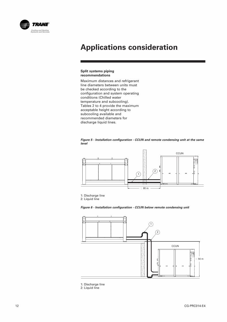
Maximum distances and refrigerantline diameters between units mustbe checked according to theconfiguration and system operatingconditions (Chilled watertemperature and subcooling).Tables 2 to 4 provide the maximumacceptable height according tosubcooling available andrecommended diameters fordischarge liquid lines.
Applications consideration
CG-PRC014-E412
Figure 5 - Installation configuration - CCUN and remote condensing unit at the same
level
1: Discharge line2: Liquid line
Figure 6 - Installation configuration - CCUN below remote condensing unit
1: Discharge line2: Liquid line
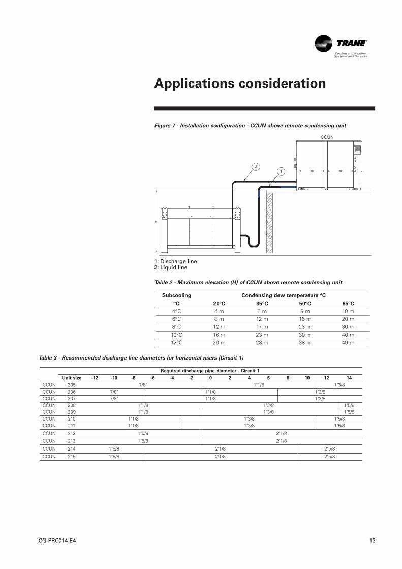
Figure 7 - Installation configuration - CCUN above remote condensing unit
1: Discharge line2: Liquid line
Table 2 - Maximum elevation (H) of CCUN above remote condensing unit
Subcooling Condensing dew temperature °C
°C 20°C 35°C 50°C 65°C
4°C 4 m 6 m 8 m 10 m6°C 8 m 12 m 16 m 20 m8°C 12 m 17 m 23 m 30 m10°C 16 m 23 m 30 m 40 m12°C 20 m 28 m 38 m 49 m
H
Applications consideration
13CG-PRC014-E4
Table 3 - Recommended discharge line diameters for horizontal risers (Circuit 1)
Required discharge pipe diameter - Circuit 1
Unit size -12 -10 -8 -6 -4 -2 0 2 4 6 8 10 12 14
CCUN 205 7/8" 1"1/8 1"3/8CCUN 206 7/8" 1"1/8 1"3/8CCUN 207 7/8" 1"1/8 1"3/8CCUN 208 1"1/8 1"3/8 1"5/8CCUN 209 1"1/8 1"3/8 1"5/8CCUN 210 1"1/8 1"3/8 1"5/8CCUN 211 1"1/8 1"3/8 1"5/8
CCUN 212 1"5/8 2"1/8
CCUN 213 1"5/8 2"1/8
CCUN 214 1"5/8 2"1/8 2"5/8
CCUN 215 1"5/8 2"1/8 2"5/8

Table 4 - Recommended discharge line diameters for horizontal risers (Circuit 2)
Table 5 - Recommended liquid line diameters for vertical or horizontal risers (Circuit 1)
Table 6 - Recommended liquid line diameters for vertical or horizontal risers (Circuit 2)
Required liquid pipe diameter - Circuit 2
Unit size -12 -10 -8 -6 -4 -2 0 2 4 6 8 10 12 14
CCUN 205 5/8" 7/8" 1"1/8CCUN 206 5/8" 7/8" 1"1/8CCUN 207 5/8" 7/8" 1"1/8CCUN 208 7/8" 1"1/8 1"3/8CCUN 209 7/8" 1"1/8 1"3/8CCUN 210 7/8" 1"1/8 1"3/8CCUN 211 7/8" 1"1/8 1"3/8
CCUN 212 1"1/8 1"3/8
CCUN 213 1"1/8 1"3/8 1"5/8
CCUN 214 1"1/8 1"3/8 1"5/8
CCUN 215 1"1/8 1"3/8 1"5/8
Required liquid line pipe diameter - Circuit 1
Unit size -12 -10 -8 -6 -4 -2 0 2 4 6 8 10 12 14
CCUN 205 5/8" 7/8" 1"1/8CCUN 206 5/8" 7/8" 1"1/8CCUN 207 5/8" 7/8" 1"1/8CCUN 208 7/8" 1"1/8 1"3/8CCUN 209 7/8" 1"1/8 1"3/8CCUN 210 7/8" 1"1/8 1"3/8CCUN 211 7/8" 1"1/8 1"3/8
CCUN 212 1"1/8 1"3/8 1"5/8
CCUN 213 1"1/8 1"3/8 1"5/8
CCUN 214 1"1/8 1"3/8 1"5/8
CCUN 215 1"1/8 1"3/8 1"5/8
Required discharge pipe diameter - Circuit 2
Unit size -12 -10 -8 -6 -4 -2 0 2 4 6 8 10 12 14
CCUN 205 7/8" 1"1/8 1"3/8CCUN 206 7/8" 1"1/8 1"3/8CCUN 207 7/8" 1"1/8 1"3/8CCUN 208 1"1/8 1"3/8 1"5/8CCUN 209 1"1/8 1"3/8 1"5/8CCUN 210 1"1/8 1"3/8 1"5/8CCUN 211 1"1/8 1"3/8 1"5/8
CCUN 212 1"3/8 1"5/8 2"1/8
CCUN 213 1"5/8 2"1/8
CCUN 214 1"5/8 2"1/8
CCUN 215 1"5/8 2"1/8 2"5/8
Applications consideration
CG-PRC014-E414
Control
15CG-PRC014-E4
Safety Controls
A centralized microcomputer offersa higher level of machineprotection. Because the safetycontrols are smarter, they limitcompressor operation in order toavoid compressor or evaporatorfailures, thereby minimizingnuisance shutdowns. Tracer™Chiller Controls directly senses thecontrol variables that govern theoperation of the chiller: evaporatorpressure, condenser pressure.When any one of these variablesapproaches a limit condition atwhich the unit may be damaged orshut down on a safety, TracerChiller Controls takes correctiveaction to avoid shutdown and keepthe chiller operating. It does thisthrough combined actions ofcompressor staging and pumpstaging. It has also the capability tocontrol the remote condenser fanstaging for condenserless unit(CCUN). Tracer Chiller Controlsoptimizes total chiller powerconsumption during normaloperating conditions. Duringabnormal operating conditions, themicroprocessor will continue tooptimize chiller performance bytaking the corrective actionnecessary to avoid shutdown. Thiskeeps cooling capacity availableuntil the problem can be solved.Whenever possible, the chiller isallowed to perform its function:make chilled water. In addition,microcomputer controls allow formore types of protection, like winterfreeze protection; the safety controlshelp keep the building or processrunning and out of trouble.
Stand-alone controls
Interfacing to stand-alone units isvery simple: only a remoteauto/stop for scheduling is requiredfor unit operation. Signals from thechilled-water pump contactorauxiliary, or a flow switch, are wiredto the chilled-water flow interlock.Signals from a time clock or someother remote device are wired tothe external auto/stop input.
Tracer™ Chiller Control human
interfaces

Standard Features External
Auto/Stop
A job-site-provided contact closurewill turn the unit on and off.
Chilled Waterflow Interlock
Unit is equipped with a water flowcontrol which allows unit operationif a load exists. This feature willallow the unit to run in conjunctionwith the pump system.
External Interlock
A job-site-provided contact openingwired to this input will turn the unitoff and require a manual reset ofthe unit microcomputer. Thisclosure is typically triggered by ajob-site-provided system such as afire alarm.
Chilled Water Pump Control
Unit controller manage operation ofthe optional chilled and hot waterpump of the chiller. When hydraulicmodules are not mounted, unitcontrols provide an output tocontrol the chilled-water pump(s).One contact closure to the chiller isall that is required to initiate thechilled-water system. Chilled waterpump control by the chiller is arequirement for all IndoorAquaStream²® chillers.
Seven day scheduling
This function provides a means ofscheduling the chiller operation ona daily basis. Thus simple chillerscheduling can be performedwithout the need for a buildingautomation system.
Alarm Indication Contacts
Four factory-installed contacts withthe following preset defaultassignments:
• Alarm • Chiller running • Maximum capacity • Chiller limit.
Additional Features that May Be
Added (require some optional
factory-installed hardware)
• Ice-making card • Tracer communication card • Chilled water and remote
current limit set point card(note: all wiring outside the unitis supplied by the contractor).
Easy Interface to a Generic Building
Management System
Controlling the Indoor AquaStream²®
chillers with building managementsystems is state-of-the-art, yetsimple with either:- the LonTalk Communications
Interface for Chillers (LCI-C) - or Generic Building Management
System Hardwire Points.
Simple Interface with Other Control
Systems
Microcomputer controls affordsimple interface with other controlsystems, such as time clocks,building automation systems, andice storage systems. This meansyou have the flexibility to meet jobrequirements while not having tolearn a complicated control system.This setup has the same standardfeatures as a stand-alone waterchiller, with the possibility of havingadditional optional features.
Control
CG-PRC014-E416
Control
17CG-PRC014-E4
What are LonTalk, Echelon, and
LonMark?
LonTalk is a communicationsprotocol developed by the EchelonCorporation. The LonMarkassociation develops controlprofiles using the LonTalkcommunication protocol. LonTalk isa unit level communicationsprotocol, unlike BACNet used at thesystem level.
LonTalk Communications Interface
for Chillers (LCI-C)
LonTalk Communications Interfacefor Chillers (LCI-C) provides ageneric automation system with theLonMark chiller profileinputs/outputs. The inputs/outputsinclude both mandatory andoptional network variables.
Note: LonMark network variablenames are in parentheses whendifferent from chiller namingconvention.
Chiller Inputs:
• Chiller Enable/Disable• Chilled Liquid Setpoint (Cool or
hot Setpoint)• Ice Making (Chiller Mode)
Chiller Enable/Disable
Allows the chiller to be started orstopped depending on if certainoperating conditions are met.
Chilled Liquid Setpoint
Allows the the external settingindependent of the front panelsetpoint to adjust the leaving watertemperature setpoint.
Hot Liquid Setpoint
Allows the external settingindependent of the front panelsetpoint to adjust the leaving watertemperature setpoint from thecondenser.
Ice Making
Provides interface with ice makingcontrol systems.
Chiller Outputs:
• On/Off Active Setpoint • Leaving Chilled Water
Temperature • Entering Chilled Water
Temperature • Leaving Hot Water
Temperature• Entering Hot Water
Temperature• Alarm Descriptor • Chiller Status

On/Off
Indicates the current state of thechiller
Active Setpoint
Indicates the current value of theleaving water temperature setpoint
Leaving Chilled Water Temperature
Provides the current leaving watertemperature
Entering Chilled Water Temperature
Provides the current entering watertemperature.
Leaving Hot Water Temperature
(Optional feature)
Provides the current leaving watertemperature from the condenser.
Entering Hot Water Temperature
(Optional feature)
Provides the current entering watertemperature from the condenser.
Alarm Descriptor
Provides alarm messages based onpredetermined criteria.
Chiller Status
Indicates the running modes andstates of the chiller, i.e. Running inalarm mode, chiller enabled, chillerbeing locally controlled, etc.
Generic Building Management
System Hardwire Points
GBAS may be achieved viahardware input/output as well. Theinput/outputs are as follows:
Chiller hardwire inputs include:
• Chiller enable/disable • Circuit enable/disable
• External chilled water setpoint -(Optional feature)
• Ice making enable – (Optionalfeature)
External Chilled Water Setpoint -
(Optional feature)
Allows the external settingindependent of the front panelsetpoint by one of two means:a) 2-10 VDC input, orb) 4-20 mA input
Chiller hardwire outputs include:
• Compressor running indication • Alarm indication (Ckt 1/Ckt 2) • Maximum capacity • Ice making status
Alarm Indication Contacts
The unit provides three single-pole/double-throw contact closures toindicate: a) Compressor on/off status b) Compressor running at
maximum capacity c) Failure has occurred (Ckt 1/Ckt 2)
These contact closures may be usedto trigger job site supplied alarmlights or alarm bells.
Ice Making Control - (Optional
feature)
Provides interface with ice makingcontrol systems.
Control
CG-PRC014-E418

Control
19CG-PRC014-E4
Tracer Summit™ Controls
— Interface with the Trane
Integrated Comfort System
(ICS)
Trane Chiller Plant Control
The Tracer Chiller Plant Managerbuilding management systemprovides building automation andenergy management functionsthrough stand-alone control. TheChiller Plant Control is capable ofmonitoring and controlling yourentire chiller plant system.
Application software available:• Time-of-day scheduling• Chiller sequencing• Process control language• Boolean processing• Zone control • Reports and logs • Custom messages • Run time and maintenance • Trend log • PID control loops
And of course, the Trane ChillerPlant Control can be used on astand-alone basis or tied into acomplete building automationsystem. When the water-cooledchiller is used in conjunction with aTrane Tracer Summit™ system, theunit can be monitored andcontrolled from a remote location.The water-cooled chiller can becontrolled to fit into the overallbuilding automation strategy byusing time-of-day scheduling, timedoverride, demand limiting, andchiller sequencing. A buildingowner can completely monitor thewater-cooled chiller from the Tracersystem, since all of the monitoringinformation indicated on themicrocomputer can be read on theunit controllers Tracer systemdisplay. In addition, all the powerfuldiagnostic information can be readback at the Tracer system. Best ofall, this powerful capability comesover a single twisted pair of wires!
Water-Cooled chillers can interfacewith many different external controlsystems, from simple stand-aloneunits to ice-making systems. Eachunit requires a single-source, three-phase power supply.
A single twisted pair of wires tieddirectly between the IndoorAquaStream²® chillers and a TracerSummit™ system provides control,monitoring, and diagnosticcapabilities. Control functionsinclude auto/stop, adjustment ofleaving-water-temperature set pointand control of ice-making mode.The Tracer system reads monitoringinformation such as entering- andleaving-evaporator-watertemperatures and entering- andleaving-condenser-watertemperatures and outdoor airtemperature. Over 60 individualdiagnostic codes can be read by theTracer system. In addition, theTracer system can providesequencing control for up to25 units on the same chilled-waterloop. Pump sequencing control canbe provided from the Tracersystem. Tracer ICS is not availablein conjunction with the external setpoint capability.
Required Options
Tracer Interface
Additional Options that May Be
Used
Ice-Making Control
External Trane Devices Required
Tracer Summit™, Tracer 100System or Tracer Chiller PlantControl
Ice-Making Systems Controls
An ice-making option may beordered with the water-cooledchiller. The unit will have twooperating modes, ice making andnormal daytime cooling. In the icemaking mode, the water-cooledchiller will operate at fullcompressor capacity until the returnchilled-fluid temperature enteringthe evaporator meets the icemaking set point. Two input signalsare required to the water-cooledchiller for the ice-making option.The first is an auto/stop signal forscheduling, and the second isrequired to switch the unit betweenthe ice-making mode and normaldaytime operation. The signals areprovided by a remote job sitebuilding-automation device such asa time clock or a manual switch. Inaddition, the signals may beprovided over the twisted wire pairfrom a Tracer™ system, or aLonTalk Communication Interfacebut will require the communicationboards provided with the IceMaking Control Option.
Additional Options That May Be
Used
- Failure Indication ContactsCommunications Interface (ForTracer Systems)
- Chilled-Water Temperature Reset
Control
CG-PRC014-E420

Selection Procedures
21CG-PRC014-E4
The performance examples, on thefollowing pages provideperformance information at variouscapacities for the most commonconditions.The stated cooling capacities arebased on:
The capacity ratings are applicableto a temperature drop within 4 to8°C except as limited by theminimum or maximum water-flowrates as indicated by the heatexchanger’s hydraulic resistancetables. If a different fouling factor isused, the unit capacity will vary. Forconditions that are not directlytabulated, direct interpolation maybe used. Extrapolation is notpermitted.
Watercooled units: CGWN
To determine the cooling capacityand the power input, the followinginformation is needed:• the required cooling capacity
(Cap.)• the evaporator leaving water
temperature (ELWT)• the condenser leaving water
temperature (CLWT)
Unit power input (P.I.), heat rejectedby condenser (RH), evaporator andcondenser waterflow rates(respectively EWFR and CWFR) andassociated pressure drops(respectively EWPD and CWPD) aregiven in the table.
Selection example:
Cooling capacity required (Cap):180 kW
Evaporator leaving watertemperature (ELWT): 7°C
Condenser leaving watertemperature (CLWT): 35°C
By using the selection table it canbe determined that the CGWN 205Standard gives a cooling capacity(cap) of 182.5 kW and a power input(P.I.) of 42.5 kW and condenserrejected heat (RH) is 224.19 kW.
Evaporator water flow rate (EWFR)is 8.71 l/s and associated pressuredrop (EWPD) is 57 kPa
Condenser water flow rate (CWFR)is 10.70 l/s and associated pressuredrop (CWPD) is 59 kPa
CGWN Water cooled chillers 5 5 0.0044CCUN Condenserless chillers 5 - 0.0044CCUN + remote condensing unitSplit system 5 - 0.0044
Evaporator
∆∆t (°C)
Condenser
∆∆t (°C)
Fouling factor
(m²/K/kW)
Performances
CG-PRC014-E422
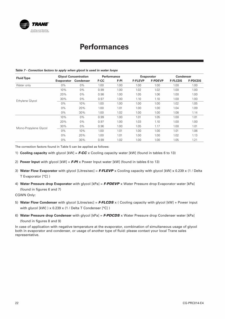
Table 7 - Correction factors to apply when glycol is used in water loops
Fluid TypeGlycol Concentration Performance Evaporator Condenser
Evaporator Condenser F-CC F-PI F-FLEVP F-PDEVP F-FLCDS F-PDCDS
Water only 0% 0% 1.00 1.00 1.00 1.00 1.00 1.00 10% 0% 0.99 1.00 1.02 1.02 1.00 1.00 20% 0% 0.98 1.00 1.05 1.06 1.00 1.00
Ethylene Glycol30% 0% 0.97 1.00 1.10 1.10 1.00 1.00 0% 10% 1.00 1.00 1.00 1.00 1.02 1.05 0% 20% 1.00 1.01 1.00 1.00 1.04 1.09 0% 30% 1.00 1.02 1.00 1.00 1.08 1.14 10% 0% 0.99 1.00 1.01 1.05 1.00 1.01 20% 0% 0.97 1.00 1.03 1.10 1.00 1.00
Mono-Propylene Glycol30% 0% 0.96 1.00 1.05 1.17 1.00 1.01 0% 10% 1.00 1.01 1.00 1.00 1.01 1.06 0% 20% 1.00 1.01 1.00 1.00 1.02 1.13 0% 30% 0.99 1.02 1.00 1.00 1.05 1.21
The correction factors found in Table 5 can be applied as follows:
1) Cooling capacity with glycol [kW] = F-CC x Cooling capacity water [kW] (found in tables 6 to 13)
2) Power Input with glycol [kW] = F-PI x Power Input water [kW] (found in tables 6 to 13)
3) Water Flow Evaporator with glycol [Litres/sec] = F-FLEVP x Cooling capacity with glycol [kW] x 0.239 x (1 / Delta
T Evaporator [°C] )
4) Water Pressure drop Evaporator with glycol [kPa] = F-PDEVP x Water Pressure drop Evaporator water [kPa]
(found in figures 6 and 7)
CGWN Only:
5) Water Flow Condenser with glycol [Litres/sec] = F-FLCDS x ( Cooling capacity with glycol [kW] + Power input
with glycol [kW] ) x 0.239 x (1 / Delta T Condenser [°C] )
6) Water Pressure drop Condenser with glycol [kPa] = F-PDCDS x Water Pressure drop Condenser water [kPa]
(found in figures 8 and 9)
In case of application with negative temperature at the evaporator, combination of simultaneous usage of glycolboth in evaporator and condenser, or usage of another type of fluid: please contact your local Trane salesrepresentative.

Performances
23CG-PRC014-E4
Table 8 - European Seasonal Energy Efficiency Ratio (ESEER) - CGWN Standard
A B C D
Model ESEER 100% load 75% load 50% load 25% load
EER EER EER EER
CGWN 205 5.96 4.29 5.23 6.36 6.50
CGWN 206 6.04 4.32 5.17 6.46 6.77
CGWN 207 6.06 4.36 5.30 6.50 6.60
CGWN 208 6.28 4.60 5.48 6.45 7.33
CGWN 209 5.81 4.45 5.14 6.11 6.41
CGWN 210 5.79 4.37 5.04 6.14 6.42
CGWN 211 5.90 4.35 5.17 6.25 6.55
CGWN 212 5.46 4.00 4.73 5.71 6.23
CGWN 213 5.53 3.97 4.90 5.69 6.34
CGWN 214 5.32 3.89 4.81 5.54 5.86
CGWN 215 5.41 4.05 4.90 5.59 6.01
EER: Energy Efficiency Ratio
Table 9 - European Seasonal Energy Efficiency Ratio (ESEER) - CGWN High Efficiency
(HE)
A B C D
Model ESEER 100% load 75% load 50% load 25% load
EER EER EER EER
CGWN 205 HE 6.39 4.82 5.66 6.74 7.02
CGWN 206 HE 6.36 4.75 5.51 6.74 7.11
CGWN 207 HE 6.39 4.71 5.62 6.78 7.00
EER: Energy Efficiency Ratio
CG-PRC014-E424
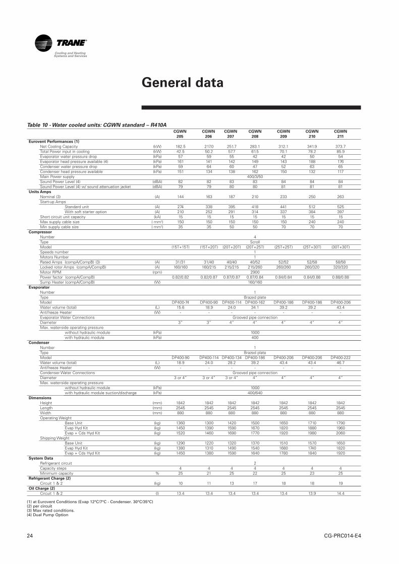
Table 10 - Water cooled units: CGWN standard – R410ACGWN CGWN CGWN CGWN CGWN CGWN CGWN
205 206 207 208 209 210 211
Eurovent Performances (1)
Net Cooling Capacity (kW) 182.5 217.0 251.7 283.1 312.1 341.9 373.7Total Power input in cooling (kW) 42.5 50.2 57.7 61.5 70.1 78.2 85.9Evaporator water pressure drop (kPa) 57 59 55 42 42 50 54Evaporator head pressure available (4) (kPa) 161 141 142 149 143 188 176Condenser water pressure drop (kPa) 59 64 60 47 52 63 65Condenser head pressure available (kPa) 151 134 138 162 150 132 117Main Power supply 400/3/50Sound Power Level (4) (dBA) 82 82 83 83 84 84 84Sound Power Level (4) w/ sound attenuation jacket (dBA) 79 79 80 80 81 81 81
Units Amps
Nominal (3) (A) 144 163 187 210 233 250 263Start-up Amps
Standard unit (A) 274 338 395 418 441 512 525With soft starter option (A) 210 252 291 314 337 384 397
Short circuit unit capacity (kA) 15 15 15 15 15 15 15Max supply cable size ( mm2) 150 150 150 150 150 240 240Min supply cable size ( mm2) 35 35 50 50 70 70 70
Compressor
Number 4Type ScrollModel (15T+15T) (15T+20T) (20T+20T) (20T+25T) (25T+25T) (25T+30T) (30T+30T)Speeds number 1Motors Number 1Rated Amps (compA/CompB) (3) (A) 31/31 31/40 40/40 40/52 52/52 52/58 58/58Locked rotor Amps (compA/CompB) (A) 160/160 160/215 215/215 215/260 260/260 260/320 320/320Motor RPM (rpm) 2900Power factor (compA/CompB) 0.82/0.82 0.82/0.87 0.87/0.87 0.87/0.84 0.84/0.84 0.84/0.88 0.88/0.88Sump Heater (compA/CompB) (W) 160/160
Evaporator
Number 1Type Brazed plateModel DP400-74 DP400-90 DP400-114 DP400-162 DP400-186 DP400-186 DP400-206Water volume (total) (L) 15.6 18.9 24.0 34.1 39.2 39.2 43.4Antifreeze Heater (W) - - - - - - -Evaporator Water Connections Grooved pipe connectionDiameter 3” 3” 4” 4” 4” 4” 4”Max. water-side operating pressure
without hydraulic module (kPa) 1000with hydraulic module (kPa) 400
Condenser
Number 1Type Brazed plateModel DP400-90 DP400-114 DP400-134 DP400-186 DP400-206 DP400-206 DP400-222Water volume (total) (L) 18.9 24.0 28.2 39.2 43.4 43.4 46.7Antifreeze Heater (W) - - - - - - -Condenser Water Connections Grooved pipe connectionDiameter 3 or 4” 3 or 4” 3 or 4” 4” 4” 4” 4”Max. water-side operating pressure
without hydraulic module (kPa) 1000with hydraulic module suction/discharge (kPa) 400/640
Dimensions
Height (mm) 1842 1842 1842 1842 1842 1842 1842Length (mm) 2545 2545 2545 2545 2545 2545 2545Width (mm) 880 880 880 880 880 880 880Operating Weight
Base Unit (kg) 1360 1300 1420 1500 1650 1710 1790Evap Hyd Kit (kg) 1450 1390 1590 1670 1820 1880 1960Evap + Cds Hyd Kit (kg) 1520 1460 1690 1770 1920 1980 2060
Shipping WeightBase Unit (kg) 1290 1220 1320 1370 1510 1570 1650Evap Hyd Kit (kg) 1380 1310 1490 1540 1680 1740 1820Evap + Cds Hyd Kit (kg) 1450 1380 1590 1640 1780 1840 1920
System Data
Refrigerant circuit 2Capacity steps 4 4 4 4 4 4 4Minimum capacity % 25 21 25 22 25 23 25
Refrigerant Charge (2)
Circuit 1 & 2 (kg) 10 11 13 17 18 18 19Oil Charge (2)
Circuit 1 & 2 (l) 13.4 13.4 13.4 13.4 13.4 13.9 14.4
(1) at Eurovent Conditions (Evap 12°C/7°C - Condenser. 30°C/35°C)(2) per circuit(3) Max rated conditions.(4) Dual Pump Option
General data

25CG-PRC014-E4
General data
Table 11 - Water Cooled units: CGWN standard - R407C
CGWN CGWN CGWN CGWN212 213 214 215
Eurovent Performances (1)Net Cooling Capacity (kW) 398.6 431.3 466.0 506.4Total Power input in cooling (kW) 97.0 106.4 117.3 125.5Evaporator water pressure drop (kPa) 40 47 49 48Evaporator head pressure available (4) (kPa) 236 218 200 187Condenser water pressure drop (kPa) 66 64 59 56Condenseur head pressure available (kPa) 159 151 147 136Main Power supply 400/3/50Sound Power Level (4) (dBA) 87 88 88 90Sound Power Level w/ sound attenuation jacket (4) (dBA) 84 85 85 87
Units AmpsNominal (3) (A) 311 337 370 400Start-up Amps
Standard unit (A) 563 588 621 655With soft starter option (A) 439 465 498 530
Short circuit unit capacity (kA) 15 15 15 15Max supply cable size (mm2) 185 185 240 240Min supply cable size (mm2) 240 240 240 240
CompressorNumber 5 6 6 6Type ScrollModel (25T+30T) (25T) (25T+30T) (30T)Speeds number 1Motors Number 1Rated Amps (compA/CompB) (3) (A) 52/62.5 52/52 52/62.5 62.5/62.5Locked rotor Amps (compA/CompB) (A) 272/310 272/272 272/310 310/310Motor RPM (rpm) 2900 2900 2900 2900Power factor (compA/CompB) 0.87/0.87 0.87/0.87 0.87/0.87 0.87/0.87Sump Heater (compA/CompB) (W) 150 150 150 150
EvaporatorNumber 1Type Brazed plateModel AC350-190DQ AC350-190DQ AC350-210DQ AC350-230DQWater volume (total) (L) 38 38 42 46Antifreeze Heater (W) - - - -Evaporator Water Connections Grooved pipe connectionsDiameter 4"Max. water-side operating pressure,
without hydraulic module (kPa) 1000 1000 1000 1000with hydraulic module (kPa) 400 400 400 400
CondenserNumber 2Type Brazed plateModel B400T- 94p / 114p B400T- 114p / 114p B400T- 114p / 144p B400T- 144p / 144pWater volume (total) (L) 19 / 23 23 / 23 23 / 29 29 / 29Antifreeze Heater (W) - - - -Condenser Water Connections Grooved pipe connectionsDiameter 5"Max. water-side operating pressure,
without hydraulic module (kPa) 1000 1000 1000 1000with hydraulic module (kPa) 400 400 400 400
Dimensions without Hydraulic ModuleHeight (mm) 1950 1950 1950 1950Length (mm) 2808 2808 2808 2808Width (mm) 878 878 878 878
Dimensions with Hydraulic ModuleHeight (mm) 1950 1950 1950 1950Length (mm) 3498 3498 3498 3498Width (mm) 878 878 878 878Operating Weight
Base Unit w/o Hyd Kit (kg) 2232 2442 2525 2640Base Unit with Hyd Kit (kg) 2128 2337 2420 2500Evap Hyd Kit (kg) 490 490 490 490Cds Hyd Kit (kg) 374 374 374 374Evap + Cds Hyd Kit (kg) 682 682 682 682
Shipping WeightBase Unit w/o Hyd Kit (kg) 2109 2315 2387 2492Base Unit with Hyd Kit (kg) 2048 2253 2326 2408Evap Hyd Kit (kg) 432 432 432 432Cds Hyd Kit (kg) 317 317 317 317Evap + Cds Hyd Kit (kg) 662 662 662 662
System DataNumber of Refrigerant circuit 2Capacity steps 5 6 6 6Minimum capacity % 18 16 15 16
Refrigerant Charge (2)Circuit A & B (kg) 22 / 21 22 / 22 25 / 23 26 / 26
Oil Charge (2)Circuit A & B (l) 20.4 / 12.6 20.4 / 20.4 18.9 / 20.4 18.9 / 18.9
(1) at Eurovent Conditions (Evap 12°C/7°C - Condenser 30°C/35°C) (3) Max rated conditions.(2) per circuit (4) Dual Pump Option
General data
CG-PRC014-E426
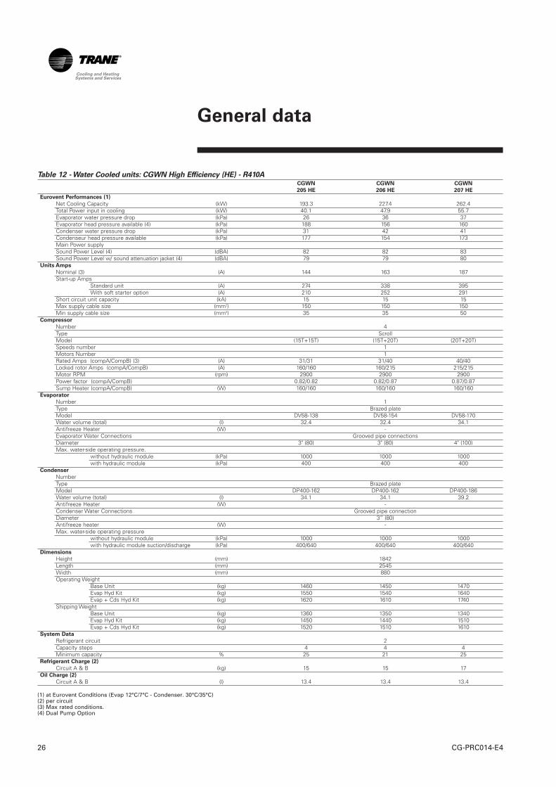
Table 12 - Water Cooled units: CGWN High Efficiency (HE) - R410ACGWN CGWN CGWN
205 HE 206 HE 207 HE
Eurovent Performances (1)
Net Cooling Capacity (kW) 193.3 227.4 262.4Total Power input in cooling (kW) 40.1 47.9 55.7Evaporator water pressure drop (kPa) 26 36 37Evaporator head pressure available (4) (kPa) 188 156 160Condenser water pressure drop (kPa) 31 42 41Condenseur head pressure available (kPa) 177 154 173Main Power supplySound Power Level (4) (dBA) 82 82 83Sound Power Level w/ sound attenuation jacket (4) (dBA) 79 79 80
Units Amps
Nominal (3) (A) 144 163 187Start-up Amps
Standard unit (A) 274 338 395With soft starter option (A) 210 252 291
Short circuit unit capacity (kA) 15 15 15Max supply cable size (mm2) 150 150 150Min supply cable size (mm2) 35 35 50
Compressor
Number 4Type ScrollModel (15T+15T) (15T+20T) (20T+20T)Speeds number 1Motors Number 1Rated Amps (compA/CompB) (3) (A) 31/31 31/40 40/40Locked rotor Amps (compA/CompB) (A) 160/160 160/215 215/215Motor RPM (rpm) 2900 2900 2900Power factor (compA/CompB) 0.82/0.82 0.82/0.87 0.87/0.87Sump Heater (compA/CompB) (W) 160/160 160/160 160/160
Evaporator
Number 1Type Brazed plateModel DV58-138 DV58-154 DV58-170Water volume (total) (l) 32.4 32.4 34.1Antifreeze Heater (W) -Evaporator Water Connections Grooved pipe connectionsDiameter 3" (80) 3" (80) 4" (100)Max. water-side operating pressure.
without hydraulic module (kPa) 1000 1000 1000with hydraulic module (kPa) 400 400 400
Condenser
NumberType Brazed plateModel DP400-162 DP400-162 DP400-186Water volume (total) (l) 34.1 34.1 39.2Antifreeze Heater (W) -Condenser Water Connections Grooved pipe connectionDiameter 3” (80)Antifreeze heater (W) -Max. water-side operating pressure
without hydraulic module (kPa) 1000 1000 1000with hydraulic module suction/discharge (kPa) 400/640 400/640 400/640
Dimensions
Height (mm) 1842Length (mm) 2545Width (mm) 880Operating Weight
Base Unit (kg) 1460 1450 1470Evap Hyd Kit (kg) 1550 1540 1640Evap + Cds Hyd Kit (kg) 1620 1610 1740
Shipping WeightBase Unit (kg) 1360 1350 1340Evap Hyd Kit (kg) 1450 1440 1510Evap + Cds Hyd Kit (kg) 1520 1510 1610
System Data
Refrigerant circuit 2Capacity steps 4 4 4Minimum capacity % 25 21 25
Refrigerant Charge (2)
Circuit A & B (kg) 15 15 17Oil Charge (2)
Circuit A & B (l) 13.4 13.4 13.4
(1) at Eurovent Conditions (Evap 12°C/7°C - Condenser. 30°C/35°C)(2) per circuit(3) Max rated conditions.(4) Dual Pump Option

General data
27CG-PRC014-E4
Table 13 - Condenserless units: CCUN standard - R410A
CCUN CCUN CCUN CCUN CCUN CCUN CCUN
205 206 207 208 209 210 211
Eurovent Performances (1)
Net Cooling Capacity (kW) 166.3 198.1 230.4 257.7 281.9 311.4 343.8Total Power input in cooling (kW) 45.6 53.8 62.0 69.8 77.7 86.4 95.1Evaporator water pressure drop (kPa) 48 49 47 35 34 41 46Evaporator head pressure available (4) (kPa) 178 161 153 160 157 200 189Main Power supply 400/3/50Sound Power Level (4) (dBA) 82 82 83 83 84 84 84Sound Power Level (4) w/ sound attenuation jacket (dBA) 79 79 80 80 81 81 81
Units Amps
Nominal (3) (A) 132 151 172 195 218 236 249Start-up Amps
Standard unit (A) 262 326 381 404 427 498 511With soft starter option (A) 198 240 277 300 323 370 383
Short circuit unit capacity (kA) 15 15 15 15 15 15 15Max supply cable size (mm2) 150 150 150 150 150 240 240Min supply cable size ( mm2) 35 35 50 50 70 70 70
Compressor
Number 4Type ScrollModel (15T+15T) (15T+20T) (20T+20T) (20T+25T) (25T+25T) (25T+30T) (30T+30T)Speeds number 1Motors Number 1Rated Amps (compA/CompB) (A) 31/31 31/40 40/40 40/52 52/52 52/58 58/58Locked rotor Amps (compA/CompB) (A) 160/160 160/215 215/215 215/260 260/260 260/320 320/320Motor RPM (rpm) 2900Power factor (compA/CompB) 0.82/0.82 0.82/0.87 0.87/0.87 0.87/0.84 0.84/0.84 0.84/0.88 0.88/0.88Sump Heater (compA/CompB) (W) 160/160
Evaporator
Number 1Type Brazed plateModel DP400-74 DP400-90 DP400-114 DP400-162 DP400-186 DP400-186 DP400-206Water volume (total) (L) 15.6 18.9 24.0 34.1 39.2 39.2 43.4Antifreeze Heater (W) - - - - - - -Evaporator Water Connections Grooved pipe connectionsDiameter 3” 3” 4” 4” 4” 4” 4”Max. water-side operating pressure
without hydraulic module (kPa) 1000with hydraulic module (kPa) 400
Remote condenser connections
Discharge line diameter circuit 1 & 2 1"3/8 1"3/8 1"3/8 1"5/8 1"5/8 1"5/8 1"5/8Liquid line diameter circuit 1 & 2 7/8 7/8 7/8 7/8 7/8 1"1/8 1"1/8
Dimensions
Height (mm) 1842 1842 1842 1842 1842 1842 1842Length (mm) 2545 2545 2545 2545 2545 2545 2545Width (mm) 880 880 880 880 880 880 880Operating Weight
Base Unit (kg) 1260 1170 1270 1280 1420 1480 1550Evap Hyd Kit (kg) 1350 1260 1440 1450 1590 1650 1720
Shipping WeightBase Unit (kg) 1210 1120 1200 1190 1320 1380 1450Evap Hyd Kit (kg) 1300 1210 1370 1360 1490 1550 1620
System Data
Refrigerant circuit 2Capacity steps 4 4 4 4 4 4 4Minimum capacity % 25 21 25 22 25 23 25
Refrigerant Charge (2)
Circuit 1 & 2 (kg) 3 3 3 3 3 3 3Oil Charge (2)
Circuit 1 & 2 (l) 13.4 13.4 13.4 13.4 13.4 13.9 14.4
(1) Conditions (Evap 12°C/7°C - Saturated discharge 45°C - 5°C subcooling)(2) per circuit(3) Max rated conditions.(4) Dual Pump Option

CG-PRC014-E428
General data
Table 14 - Condenserless units: CCUN standard - R407C
CCUN CCUN CCUN CCUN
212 213 214 215
Eurovent Performances (1)
Net Cooling Capacity (kW) 385.6 417.3 450.4 486.9Total Power input in cooling (kW) 99.0 108.5 120.5 131.1Evaporator water pressure drop (kPa) 38 44 46 45Evaporator head pressure available (4) (kPa) 242 227 211 197Main Power supply 400/3/50Sound Power Level (4) (dBA) 87 88 88 90Sound Power Level w/ sound attenuation jacket (4) (dBA) 84 85 85 87
Units Amps
Nominal (3) (A) 280 306 339 369Start-up Amps
Standard unit (A) 532 557 590 624With soft starter option (A) 408 434 467 499
Short circuit unit capacity (kA) 15 15 15 15Max supply cable size (mm2) 185 185 240 240Min supply cable size (mm2) 240 240 240 240
Compressor
Number 5 6 6 6Type ScrollModel (25T+30T) (25T) (25T+30T) (30T)Speeds number 1Motors Number 1Rated Amps (compA/CompB) (3) (A) 52/62.5 52/52 52/62.5 62.5/62.5Locked rotor Amps (compA/CompB) (A) 272/310 272/272 272/310 310/310Motor RPM (rpm) 2900 2900 2900 2900Power factor (compA/CompB) 0.87/0.87 0.87/0.87 0.87/0.87 0.87/0.87Sump Heater (compA/CompB) (W) 150 150 150 150
Evaporator
Number 1Type Brazed plateModel AC350-190DQ AC350-190DQ AC350-210DQ AC350-230DQWater volume (total) (l) 38 38 42 46Antifreeze Heater (W) no no no noEvaporator Water Connections Grooved pipe connectionsDiameter 4"Max. water-side operating pressure,
without hydraulic module (kPa) 1000 1000 1000 1000with hydraulic module (kPa) 400 400 400 400
Remote condenser connections
Discharge line diameter circuit 1 & 2 2"1/8 2"1/8 2"1/8 2"1/8Liquid line diameter circuit 1 & 2 1"3/8 1"3/8 1"3/8 1"3/8
Dimensions without Hydraulic Module
Height (mm) 1950 1950 1950 1950Length (mm) 2808 2808 2808 2808Width (mm) 878 878 878 878
Dimensions with Hydraulic Module
Height (mm) 1950 1950 1950 1950Length (mm) 3498 3498 3498 3498Width (mm) 878 878 878 878Operating Weight
Base Unit w/o Hyd Kit (kg) 1879 2070 2120 2180Base Unit with Hyd Kit (kg) 1880 2071 2122 2182Evap Hyd Kit (kg) 490 490 490 490
Shipping WeightBase Unit w/o Hyd Kit (kg) 1832 2023 2070 2130Base Unit with Hyd Kit (kg) 1842 2033 2080 2136Evap Hyd Kit (kg) 432 432 432 432
System Data
Refrigerant circuit 2Capacity steps 4 4 4 4Minimum capacity % 22 33 30 33
Refrigerant Charge (2)
Circuit A & B (kg) Holding chargeOil Charge (2)
Circuit A & B (l) 20.4 / 12.6 20.4 / 20.4 18.9 / 20.4 18.9 / 18.9
(1) Conditions (Evap 12°C/7°C - Saturated discharge 45°C - 5°C subcooling) (3) Max rated conditions.(2) per circuit (4) Dual Pump Option

29CG-PRC014-E4
General data
Table 15 - Condenserless units: CCUN High Efficiency (HE) - R410A
CCUN CCUN CCUN
205 HE 206 HE 207 HE
Eurovent Performances (1)
Net Cooling Capacity (kW) 175.0 206.7 239.1Total Power input in cooling (kW) 45.6 53.8 62.0Evaporator water pressure drop (kPa) 22 29 30Evaporator head pressure available (4) (kPa) 190 170 170Main Power supply 400/3/50Sound Power Level (4) (dBA) 82 82 83Sound Power Level w/ sound attenuation jacket (4) (dBA) 79 79 80
Units Amps
Nominal (3) (A) 132 151 172Start-up Amps
Standard unit (A) 262 326 381With soft starter option (A) 198 240 277
Short circuit unit capacity (kA) 15 15 15Max supply cable size (mm2) 150 150 150Min supply cable size (mm2) 35 35 50
Compressor
Number 4Type ScrollModel (15T+15T) (15T+20T) (20T+20T)Speeds number 1Motors Number 1Rated Amps (compA/CompB) (3) (A) 31/31 31/40 40/40Locked rotor Amps (compA/CompB) (A) 160/160 160/215 215/215Motor RPM (rpm) 2900 2900 2900Power factor (compA/CompB) 0.82/0.82 0.82/0.87 0.87/0.87Sump Heater(compA/CompB) (W) 160/160 160/160 160/160
Evaporator
Number 1Type Brazed plateModel DP400-154 DP400-154 DP400-162Water volume (total) (L) 32.4 32.4 34.1Antifreeze Heater (W) -Evaporator Water Connections Grooved pipe connectionsDiameter 3"Max. water-side operating pressure
without hydraulic module (kPa) 1000 1000 1000with hydraulic module (kPa) 400 400 400
Remote condenser connections
Discharge line diameter circuit 1 & 2 1"3/8Liquid line diameter circuit 1 & 2 7/8 7/8 7/8
Dimensions
Height (mm) 1842Length (mm) 2545Width (mm) 880Operating Weight
Base Unit (kg) 1330 1240 1250Evap Hyd Kit (kg) 1420 1330 1420
Shipping WeightBase Unit (kg) 1270 1170 1160Evap Hyd Kit (kg) 1360 1260 1330
System Data
Refrigerant circuit 2Capacity steps 4Minimum capacity % 25 21 25
Refrigerant Charge (2)
Circuit 1 & 2 (kg) Holding chargeOil Charge (2)
Circuit 1 & 2 (l) 13.4 13.4 13.4
(1) Conditions (Evap 12°C/7°C - Saturated discharge 45°C - 5°C subcooling) (3) Max rated conditions.(2) per circuit (4) Dual Pump Option

General data
CG-PRC014-E430
Table 16 - Evaporator hydraulic module
205 206 207 208 209 210 211 212 213 214 215
High head pressure optionNb Pump set 1Motor (1)(2) (kW) 4.0 4.0 5.5 5.5 5.5 7.5 7.5 11.0 11.0 11.0 11.0Rated Amps (1)(2) (A) 7.5 7.5 11.1 11.1 11.1 14.7 14.7 20.0 20.0 20.0 20.0Motor RPM (rpm) 2900
Low head pressure optionNb Pump set 1Motor (1)(2) (kW) 2.2 2.2 4.0 4.0 4.0 5.5 5.5 4.0 4.0 5.5 5.5Rated Amps (1)(2) (A) 4.0 4.0 7.5 7.5 7.5 11.1 11.1 7.8 7.8 10.3 10.3Motor RPM (rpm) 2900
Expansion tank volume (l) 25 25 25 25 25 25 25 35 35 35 35User volume expansion capacity (3) (l) 3600 3600 3600 3600 3600 3600 3600 5100 5100 5100 5100Water strainer diameter 3" 3" 4" 4" 4" 4" 4" 4" 4" 4" 4"Piping Steel
Table 17 - Condenser hydraulic module
205 206 207 208 209 210 211 212 213 214 215
High head pressure optionNb Pump set 2 (in parallel)Motor (1)(2) (kW) 3 3 4 4 4 4 4 7.5 7.5 7.5 7.5Rated Amps (1)(2) (A) 6.1 6.1 7.7 7.7 7.7 7.7 7.7 13.8 13.8 13.8 13.8Motor RPM (rpm) 2900
Low head pressure optionNb Pump set 2 (in parallel)Motor (1)(2) (kW) 2.2 2.2 3.0 3.0 3.0 3.0 3.0 4.0 4.0 5.5 5.5Rated Amps (1)(2) (A) 4.2 4.2 6.1 6.1 6.1 6.1 6.1 7.8 7.8 10.3 10.3Motor RPM (rpm) 2900
Water strainer diameter 4" 4" 4" 4" 4" 4" 4" 4" 4" 4" 4"Piping Steel
(1) per motor(2) Dual Pump Option(3) Hydrostatic pressure 3 bar at 25°C with 7°C mini
Hydraulic data
31CG-PRC014-E4
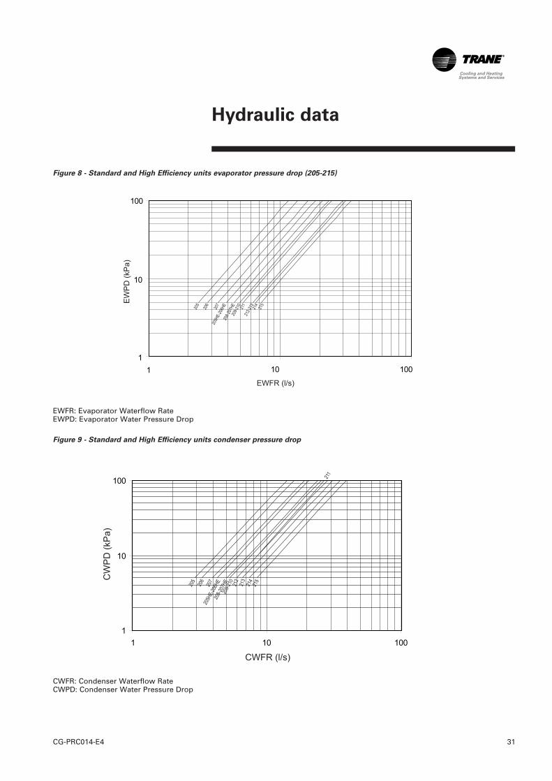
Figure 8 - Standard and High Efficiency units evaporator pressure drop (205-215)
EWFR: Evaporator Waterflow RateEWPD: Evaporator Water Pressure Drop
Figure 9 - Standard and High Efficiency units condenser pressure drop
CWFR: Condenser Waterflow RateCWPD: Condenser Water Pressure Drop

Hydraulic data
CG-PRC014-E432
Figure 10 - Evaporator available pressure - Standard and High Efficiency units – Low head pressure – Single pump
EWFR: Evaporator Waterflow Rate EWPD: Evaporator Water Pressure Drop
Figure 11 - Evaporator available pressure - Standard and High Efficiency units – Low head pressure – Dual pump
EWFR: Evaporator Waterflow RateEWPD: Evaporator Water Pressure Drop
Hydraulic data
33CG-PRC014-E4
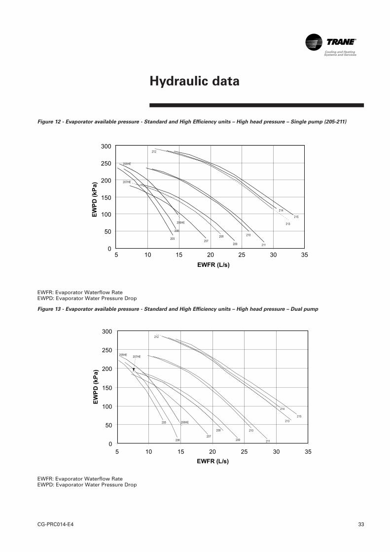
Figure 12 - Evaporator available pressure - Standard and High Efficiency units – High head pressure – Single pump (205-211)
EWFR: Evaporator Waterflow Rate EWPD: Evaporator Water Pressure Drop
Figure 13 - Evaporator available pressure - Standard and High Efficiency units – High head pressure – Dual pump
EWFR: Evaporator Waterflow RateEWPD: Evaporator Water Pressure Drop

CG-PRC014-E434
Figure 14 - Condenser available pressure - Standard and High Efficiency units – Low head pressure
CWFR: Condenser Waterflow Rate CWPD: Condenser Water Pressure Drop
Figure 15 - Condenser available pressure - Standard and High Efficiency units – High head pressure (205-211)
CWFR: Condenser Waterflow Rate CWPD: Condenser Water Pressure Drop
Hydraulic data

35CG-PRC014-E4
Sound performances
Table 18 - Sound Power Level - standard and high efficiency units without compressor sound jacket
Sound Power Level Lw (d(B))
Size 63 Hz 125 Hz 250 Hz 500 Hz 1 kHz 2 kHz 4 kHz 8 kHz
205 93 dB 75 dB 76 dB 84 dB 71 dB 69 dB 65 dB 64 dB 82 dBA206 92 dB 75 dB 76 dB 82 dB 75 dB 71 dB 67 dB 65 dB 82 dBA207 92 dB 75 dB 76 dB 84 dB 76 dB 73 dB 68 dB 64 dB 83 dBA208 91 dB 73 dB 76 dB 83 dB 78 dB 74 dB 69 dB 65 dB 83 dBA209 91 dB 74 dB 77 dB 84 dB 79 dB 75 dB 70 dB 65 dB 84 dBA210 91 dB 80 dB 81 dB 84 dB 78 dB 73 dB 67 dB 61 dB 84 dBA211 91 dB 80 dB 80 dB 84 dB 80 dB 74 dB 69 dB 64 dB 84 dBA212 94 dB 84 dB 89 dB 84 dB 79 dB 80 dB 71 dB 64 dB 87 dBA213 95 dB 87 dB 88 dB 85 dB 81 dB 81 dB 73 dB 66 dB 88 dBA214 84 dB 87 dB 88 dB 84 dB 83 dB 81 dB 74 dB 67 dB 88 dBA215 95 dB 89 dB 88 dB 86 dB 85 dB 83 dB 76 dB 69 dB 90 dBA
* High efficiency not available for sizes 212 to 215
Table 19 - Sound Power Level - standard and high efficiency units with compressor sound jacket
Sound Power Level Lw (d(B))
Size 63 Hz 125 Hz 250 Hz 500 Hz 1 kHz 2 kHz 4 kHz 8 kHz
205 92 dB 74 dB 75 dB 81 dB 67 dB 62 dB 60 dB 55 dB 79 dBA206 91 dB 74 dB 74 dB 80 dB 71 dB 65 dB 61 dB 56 dB 79 dBA207 91 dB 74 dB 76 dB 82 dB 72 dB 66 dB 63 dB 56 dB 80 dBA208 90 dB 73 dB 75 dB 81 dB 74 dB 68 dB 64 dB 57 dB 80 dBA209 90 dB 73 dB 76 dB 81 dB 74 dB 69 dB 64 dB 57 dB 81 dBA210 93 dB 79 dB 80 dB 82 dB 75 dB 67 dB 64 dB 58 dB 81 dBA211 93 dB 79 dB 79 dB 81 dB 76 dB 69 dB 64 dB 62 dB 81 dBA212 91 dB 85 dB 89 dB 83 dB 74 dB 75 dB 66 dB 55 dB 84 dBA213 91 dB 85 dB 89 dB 83 dB 77 dB 77 dB 68 dB 57 dB 85 dBA214 91 dB 85 dB 88 dB 83 dB 77 dB 78 dB 70 dB 59 dB 85 dBA215 92 dB 87 dB 88 dB 84 dB 81 dB 78 dB 71 dB 60 dB 87 dBA
* High efficiency not available for sizes 212 to 215
The sound power levels above are valid for:- CGWN water cooled chillers operating at a condenser leaving water temperature below or equal to 40°C- CCUN condenserless chillers operating at a saturated condensing temperature below or equal to 45°CShould the units operate at different conditions, apply correction factors to global sound pressure as described in the table below.
Table 20 - Correction factors for other conditions
Without compressor sound
jacket
With compressor sound
jacket
CGWN Condenser leaving watertemperature
40 to 50 °C + 1 dB(A) + 2 dB(A)
50 to 58°C + 2 dB(A) + 4 dB(A)
CCUN Saturated condensing temperature45 to 55°C + 1 dB(A) + 2 dB(A)
55 to 63°C + 2 dB(A) + 4 dB(A)
GlobaldB(A)
GlobaldB(A)

CG-PRC014-E436
Figure 16 - CGWN refrigerant flow chart (205-211)
Figure 17 - CGWN refrigerant flow chart (212-215)
1: Scroll compressor 2: Brazed plate evaporator 3: Brazed plate condenser 4: Filter drier 5: Expansion valve 6: ¼ SAE Male pressure tab
7: Discharge line 8: Liquid Line9: Suction LinePi: GaugePT: Pressure transducerPZH: High pressure switch
Sound performances
37CG-PRC014-E4
Units schematics
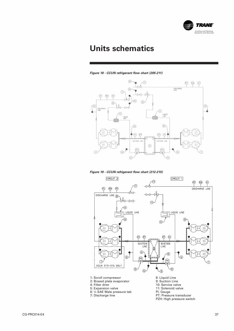
Figure 18 - CCUN refrigerant flow chart (205-211)
Figure 19 - CCUN refrigerant flow chart (212-215)
1: Scroll compressor2: Brazed plate evaporator4: Filter drier5: Expansion valve6: ¼ SAE Male pressure tab7: Discharge line
8: Liquid Line9: Suction Line10: Service valve11: Solenoid valvePi: GaugePT: Pressure transducerPZH: High pressure switch
10
11

CG-PRC014-E438
Figure 20 - CGWN hydraulic flow chart – without hydraulic module (205-211)
Figure 21 - CGWN hydraulic flow chart – without hydraulic module (212-215)
1: Insulated evaporator2: Valve for air vent3: ¼ SAE Male pressure tab4: ¼ SAE Male drain tab5: Condenser
CW: Chilled water loopHW: Condensation water loopTT: Temperature sensorFT: Water flow switch
CW
HW
3
3
21
3
3
4
4
5
CW
HW
1 2 3
4
5 4
23
3
3
Units schematics
39CG-PRC014-E4
Units schematics
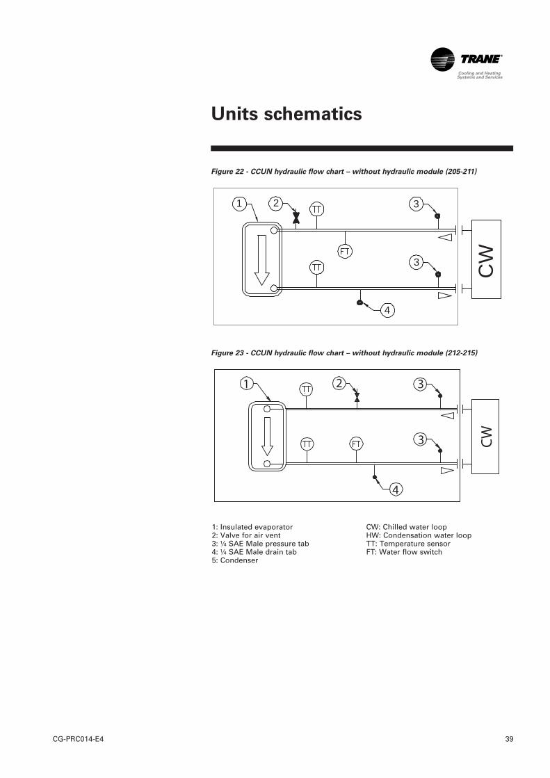
Figure 22 - CCUN hydraulic flow chart – without hydraulic module (205-211)
Figure 23 - CCUN hydraulic flow chart – without hydraulic module (212-215)
1: Insulated evaporator2: Valve for air vent3: ¼ SAE Male pressure tab4: ¼ SAE Male drain tab5: Condenser
CW: Chilled water loopHW: Condensation water loopTT: Temperature sensorFT: Water flow switch
CW
1 2 3
4
3

CG-PRC014-E440
Figure 24 - CGWN hydraulic flow chart – with hydraulic module (205-211)
1: Insulated evaporator2: Valve for air vent3: ¼ SAE Male pressure tab4: ¼ SAE Male drain tab5: Condenser6: Water strainer7: Expansion Tank8: Pressure relief valve9: Single or double evaporator pump10: Drain pan 11: Condenser pump12: Check valve
CW: Chilled water loopHW: Condensation water loopTT: Temperature sensorPi: Pressure gaugeFT: Water flow switchA: For sizes 205 to 207 standard head 3"B: For sizes 208 to 211 and all sizes high 4"
CW
HW
1
2
2
3
3
3
3
4
44
4
6
6
7 8
9 10
5
12
1112
11
Units schematics
41CG-PRC014-E4
Units schematics
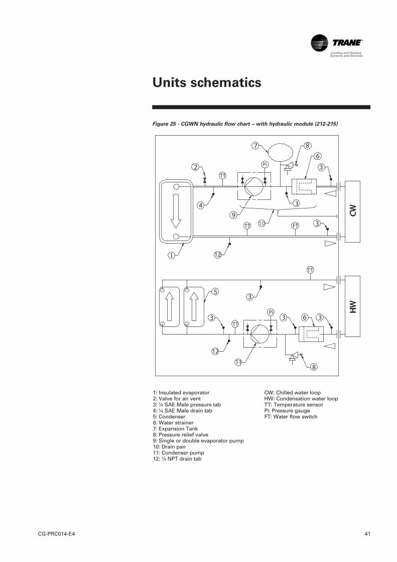
Figure 25 - CGWN hydraulic flow chart – with hydraulic module (212-215)
1: Insulated evaporator2: Valve for air vent3: ¼ SAE Male pressure tab4: ¼ SAE Male drain tab5: Condenser6: Water strainer7: Expansion Tank8: Pressure relief valve9: Single or double evaporator pump10: Drain pan 11: Condenser pump12: ¼ NPT drain tab
CW: Chilled water loopHW: Condensation water loopTT: Temperature sensorPi: Pressure gaugeFT: Water flow switch

CG-PRC014-E442
Figure 26 - CCUN hydraulic flow chart – with hydraulic module (205-211)
Figure 27 - CCUN hydraulic flow chart – with hydraulic module (212-215)
1: Insulated evaporator2: Valve for air vent3: ¼ SAE Male pressure tab4: ¼ SAE Male drain tab6: Water strainer7: Expansion Tank
8: Pressure relief valve9: Single or double evaporator pump10: Drain pan11: ¼ NPT drain tabCW: Chilled water loopTT: Temperature sensorPi: Pressure gauge
Units schematics

43CG-PRC014-E4
Units schematics
Figure 28 - CGWN - CCUN units dimensions
Table 21 - CGWN – CCUN dimensions
Unit Dimensions
X mm Y mm Z mm
Unit with Hydraulic Module
2545 880 1842
CGWN - CCUN 205CGWN - CCUN 206CGWN - CCUN 207CGWN - CCUN 208CGWN - CCUN 209CGWN - CCUN 210CGWN - CCUN 211CGWN - CCUN 212
3498 878 1950CGWN - CCUN 213CGWN - CCUN 214CGWN - CCUN 215Unit without Hydraulic Module
2545 880 1842
CGWN - CCUN 205CGWN - CCUN 206CGWN - CCUN 207CGWN - CCUN 208CGWN - CCUN 209CGWN - CCUN 210CGWN - CCUN 211CGWN - CCUN 212
2808 878 1950CGWN - CCUN 213CGWN - CCUN 214CGWN - CCUN 215

CG-PRC014-E444
CGWN CCUN Indoor chiller
Indoor scroll compressor liquidchiller
• CGWN: packaged water cooled
• CCUN: Condenserless, for
installation with a remotecondenser
With following characteristics:- operating with HFC-based
refrigerant like R407C. - furnished with scroll compressors,
brazed plate evaporator, withmicroprocessor based control.
- comply with EC requirements forMachinery, Electromagnetic andPressure Equipment Directives(98/37/CE directive), as amended,and with national implementinglegislation.
- designed and manufactured inaccordance with the qualityassurance ISO 9001/BS ENISO9001.
- certified and rated in accordancewith Eurovent standard.
- designed for indoor applicationand painted.
2. Compressors
- Hermetic scroll compressors:- Direct-drive 2900 rpm- suction gas-cooled hermetic
motor- built-in centrifugal oil pump
3. Evaporator
- Brazed plate heat exchanger,made of stainless steel and copperbrazing.
- insulated with vinyl based closedcell insulation.
4. Condenser (CGWN only)
- 180-350 kW: One single brazedplate heat exchanger, made ofstainless steel and copper brazing
- 350-500 kW: Two brazed plate heatexchanger in parallel made of
stainless steel and copper brazing.
5. Unit construction
- Unit structure made of 2 mm steelprofile, supporting casing andelectrical panels made ofgalvanized steel 1 mm thick,entirely painted, integratingaccessible and appropriate riggingpoints for an easy and safehandling at job site. The powderpaint system (white color:RAL 9002) applied on the metalsheets of the casing withstand500 hours in a salt-spray fog testminimum.
- Electrical panels fully mountedand wired in factory, with fullopening access doors.
6. Refrigerant circuit
- All units have 2 refrigerationcircuits, with:- 180-350 kW: Two (manifolded)
compressors on each circuit- 350-500 kW: Three (manifolded)
compressors on each circuit.
Note:
Size 212 has 2+3 manifoldedcompressor- Provided for each refrigerant
circuit:- High and Low pressure
transducers.- Replaceable liquid filter-dryer. - Oil level sight glass and oil
charging valve.- One thermostatic expansion
valve per refrigerant circuit- Pressure port on each
refrigerant line.- High pressure side dual
pressure switch.CGWN only: full operating charge ofHFC-407C or R410A and P.O.E. oil. CCUN only: holding charge ofHFC-407C or R410A and operatingcharge P.O.E. oil. Liquid linesolenoid valve, discharge and liquidline service valves.
7. Water side piping
- Field pipe connections Victaulictype provided at the outside of theunit casing.
- Electronic chilled water flowswitch, factory installed.
Mechanical Specifications

45CG-PRC014-E4
Mechanical Specifications
Condenser side
- For:180-350 kW: 2 centrifugal simplepumps factory installed,operating in cascade to optimizeenergy consumption based onunit capacity. As an option,pumps with separate variablespeed drives can be supplied.350-500 kW: Twin pump withpump discharge check valves
- Pump rated for 0.64 MPaworking pressure. As an option,pumps with integrated variablespeed drive can be supplied.
- Water strainer to protect againstparticles with a diameter above1.6 mm, “T” shape, cleanable byopening only one Victualicconnection.
8. Control panel
- Weatherproof control panel,containing starters, power andcontrol wiring, mounted on thechiller, and include primary andsecondary fused control powertransformer with 2 secondarycontrol circuits:
- 230 volt single phase connectionfor evaporator freeze protectionheaters and control circuit,
- 24 volt single phase connectionfor electronic part of the controlcircuit.
- The power panel door locked bya main disconnect switch.
Hydraulic module option:
- Fitted inside the chiller.
Evaporator side
- For:180-350 kW: Monocell centrifugalsingle or twin pump factoryinstalled, twin pump systemhave pump discharge checkvalves350-500 kW: Twin pump withpump discharge check valves
- Pump crankcase of cast iron withclosed type impeller,dynamically balanced.
- Pump rated for 1.2 MPa workingpressure.
- Pre-charged expansion tank- Water strainer to protect against
particles with a diameter above1.6 mm, “T” shape, cleanable byopening only one Victualicconnection.
- Gauge tappings allow tomeasure evaporator pressuredrop and available pressuredrop.
- 400 kPa relief valve
9. Unit Controls (CH530)
The microprocessor-based controlpanel is factory-installed andfactory-tested. Chilled water resetbased on return water is standard.The CH530 microprocessorautomatically acts to prevent unitshutdown due to abnormaloperating conditions associatedwith low evaporator refrigeranttemperature, high condensingtemperature, and/or motor currentoverload. If an abnormal operatingcondition continues and theprotective limit is reached, themachine should shut down.
The panel includes machineprotection shutdown requiringmanual reset for the followingconditions:• low evaporator refrigerant
temperature and pressure• high condenser refrigerant
pressure• critical sensor or detection circuit
faults• motor current overload• high compressor discharge
temperature• lost communication between
main processor and LLID• external and local emergency
stop

CG-PRC014-E446
The panel also includes machineprotection shutdown with automaticreset for the following correctableconditions:• power loss• loss of evaporator or condenser
water flow
When a fault is detected, the controlsystem conducts more than60 diagnostic checks and displaysresults.
The display will identify the fault,indicate date, time, and operatingmode at time of occurrence, andprovide type of reset required and ahelp message. The diagnostichistory will display the last tendiagnostics with their times anddates of occurrence.
DynaView Panel
Factory-mounted to the controlpanel door, the operator interfacehas an LCD touch-screen display foroperator input and informationoutput. This interface providesaccess to the following information:evaporator report, condenserreport, compressor report. Alldiagnostics and messages aredisplayed in “clear language.”
Data contained in available reportsincludes: • refrigerant pressure and
temperatures• flow switch status• compressor starts and run-time
All necessary settings and set-points are programmed into themicroprocessor based controller viathe operator interface. Thecontroller is capable of receivingsignals contemporaneously from avariety of control sources, in anycombination, and priority order ofcontrol sources can beprogrammed. The control sourcewith priority determines active set-points via the signal it sends to thecontrol panel.
Control sources may be:• the local operator interface
(standard)• a 4-20 mA or 2-10 VDC signal
from an external source(interface optional; controlsource not supplied)
• Trane Tracer Summit™ system(interface optional)
• LonTalk LCI-C (interface optional;control source not supplied)
Optional capabilities:• water (CDS Inlet/Outlet) and air
(outside ambient/zone)temperatures
• electrical distribution faults:current loss or phase reversal.
Mechanical Specifications

47CG-PRC014-E4
Notes

For additional information, contact :
Distributor / Installer stamp
The manufacturer has a policy of continuousproduct improvement, and reserves the right to alterany details of the products at any time withoutnotice.
This publication is a general guide to install, useand properly maintain our products. Theinformation given may be different from thespecification for a particular country or for a specificorder. In this event, please refer to your nearestoffice.
Literature Order Number CG-PRC014-E4
Date 1209
Supersedes CG-PRC014-E4_0908
Trane has a policy of continuous product and product data improvement and reserves the right tochange design and specifications without notice. Only qualified technicians should perform theinstallation and servicing of equipment referred to in this publication.
www.trane.com
For more information, contact your local sales office or e-mail us at [email protected]
Trane bvba Lenneke Marelaan 6 -1932 Sint-Stevens-Woluwe, BelgiumON 0888.048.262 - RPR BRUSSELS