Embed Size (px)
Citation preview

Indoor Flyers Grades 3-12 90-120 mins
LEARNING GOALS: After the completion of this workshop, students will understand:
1. How airplanes fly
2. Bernoulli’s principle
3. How to control an airplane, and use of mathematics to calculate average distance traveled.
CONCEIVE – What do I wish to accomplish through this project?
This stage involves guiding students in defining the goals of the project, then helping them develop conceptual, technical and
action plans to meet those goals while considering the technology, knowledge, and skills that apply. This guidance is provided
in the form of Essential Questions that use student’s preconceptions, and misperceptions then move them toward a deeper
and more realistic understanding of the process and skills needed to complete the project.
ESSENTIAL QUESTIONS:
1. How do airplanes fly?
2. What components are necessary to achieve lift and control of an airplane?
DESIGN - How will I accomplish the project?
This stage focuses on creating the plans, drawings and algorithms that describe the product, process or system that will be
implemented.
http://www.midwestproducts.com/store/product/e0a83f56-9ef4-4c91-b7a7-
9e3576d89375/Delta_Dart_Class_Pack_-_Supplies_35_students.aspx
We purchased kits from Midwest products for students to construct a Delta Dart model airplane that is powered by
using a rubber band.
Instructions on building the plane are included in the kits. A .pdf of instructions is also included.
NOTES: There are instructional materials included with kits. See Appendix A. Discuss Why Airplanes Fly?
Section before you start the project.
IMPLEMENT - From an idea to a product! This stage refers to the transformation of the design into a product. It includes hardware, manufacturing, software coding,
testing and validation.
NOTES: See above. Building instructions included with kit. After the students have built their planes
and are flying them. Then discuss design changes or corrections they would make to fly differently, straighter, etc.
If time permits you can also include a worksheet that allows them to measure their planes flight path over a series
of flights and calculate the average distance traveled.
This includes some mathematics into the workshop.
OPERATE – Does it work the way I planned? This stage uses the built product, process or system to satisfy the intended goal.

If the plane is flying poorly or making diving turns into the ground, correct this by installing trim tabs. Trim tab
ailerons can be made of stiff typewriter paper measureing ¾” x 2” amd ise a glue stick to apply them on the edge of
the back wings. (an illustration is included in instruction #27 Appendix 2). They can also add horizontal stablilizers
(see instruction#28) or add a tab to the tail fin as a rudder to collect hard, tight turns.
NOTES:
RESOURCES NEEDED – What equipment and supplies do I need?
http://www.midwestproducts.com/store/product/e0a83f56-9ef4-4c91-b7a7-
9e3576d89375/Delta_Dart_Class_Pack_-_Supplies_35_students.aspx
In addition you will need:
A piece of corrugated cardboard or drywall or wall board approximately 12” x 15” to serve as a work pad.
Wood glue
A glue stick
Straight pins
Scotch tape
Scissors
A hobby knife or razor blade (depending on age group)
SET-UP
See above supplies needed.
Colorado State Standards - High School 21st Century Skills 1. Physical Science Concepts and skills students master:
1.Newton's laws of motion and gravitation describe the relationships among forces acting on and between objects, their masses, and changes in their motion - but have limitations. 5.Energy exists in many forms such as mechanical, chemical, electrical, radiant, thermal, and nuclear, that can be quantified and experimentally determined
Inquiry Questions:
1. What factors can be
measured to determine the
amount of energy associated
with an object?
2. What are the most common
forms of energy in our
physical world?
3. What makes an energy form
renewable or nonrenewable?
4. What makes some forms of
energy hard to measure?
Colorado State Standards – 8th Grade 21st Century Skills 1.Physical Science Concepts and skills students master:
1. Identify and calculate the direction and Inquiry Questions:

magnitude of forces that act on an object, and explain the results in the object's change of motion
1. What relationships exists
among force, mass, speed,
and acceleration?
2. What evidence indicates a
force has acted on a system?
Is it possible for a force to
act on a system without
having an effect?
Relevance & Application:
1. Engineers take forces into
account when designing
moving objects such as car
tires, roller coasters, and
rockets.
2. Vehicles and their propulsion
systems are designed by
analyzing the forces that act
on the vehicle.
Colorado State Standards – 7th Grade N/A
Colorado State Standards – 6th Grade N/A
Colorado State Standards – 5th Grade N/A
Colorado State Standards – 4th Grade 21st Century Skills
N/A
Colorado State Standards – 3rd Grade 21st Century Skills N/A
Supply Price http://www.midwestproducts.com/store/product/e0a83f56-9ef4-4c91-b7a7-9e3576d89375/Delta_Dart_Class_Pack_-_Supplies_35_students.aspx
$49.99 for 35 kits
Total $1.48 per student
* 3-4 staff recommended
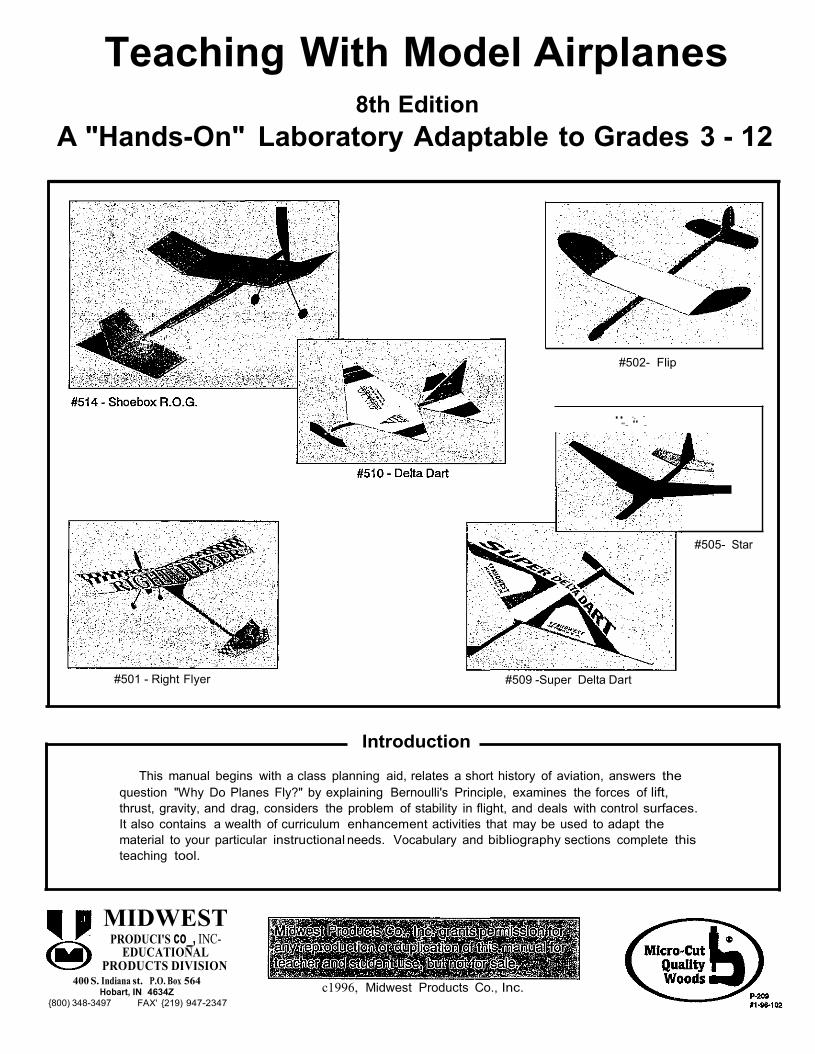
Teaching With Model Airplanes
8th Edition
A "Hands-On" Laboratory Adaptable to Grades 3 - 12
#502- Flip
.. -, - "- '' -
#505- Star
#501 - Right Flyer #509 -Super Delta Dart
Introduction
This manual begins with a class planning aid, relates a short history of aviation, answers the
question "Why Do Planes Fly?" by explaining Bernoulli's Principle, examines the forces of lift,
thrust, gravity, and drag, considers the problem of stability in flight, and deals with control surfaces.
It also contains a wealth of curriculum enhancement activities that may be used to adapt the
material to your particular instructional needs. Vocabulary and bibliography sections complete this
teaching tool.
MIDWEST PRODUCI'S co_, INC
EDUCATIONAL PRODUCTS DIVISION
400 S. Indiana st. P.O. Box 564 Hobart, IN 4634Z
{800) 348-3497 FAX' {219) 947-2347
c1996, Midwest Products Co., Inc.
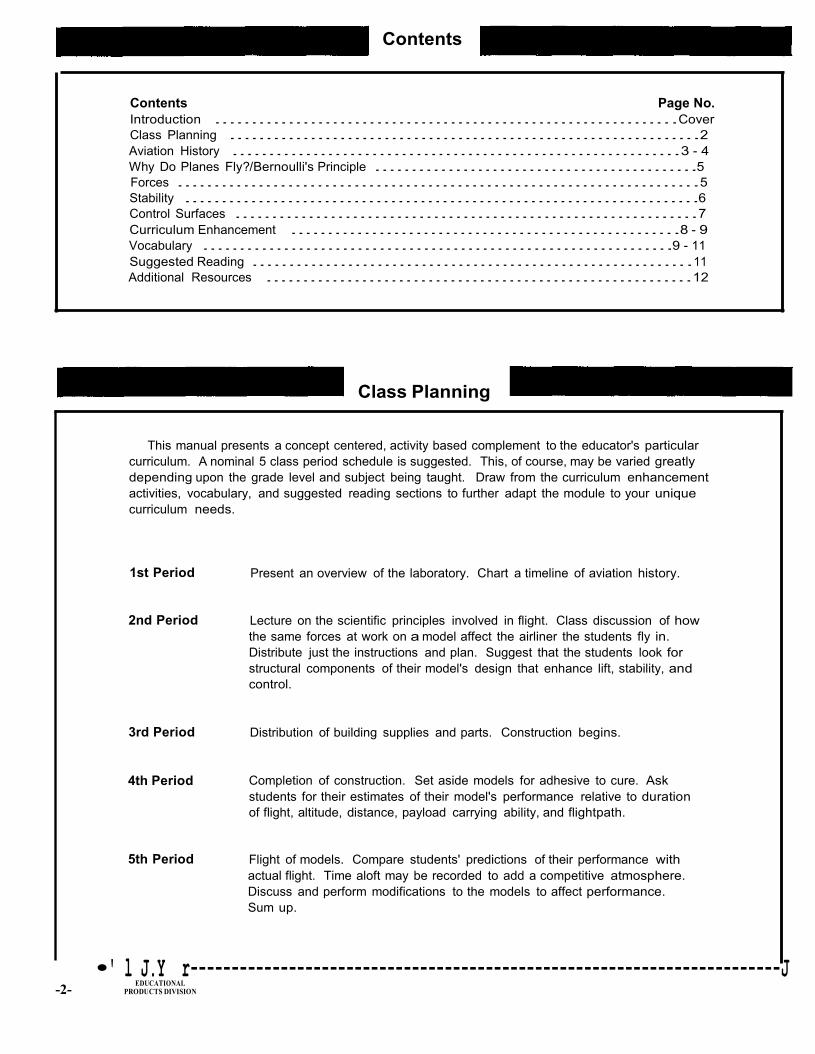
Contents
Contents Page No.
Introduction ...............................................................Cover
Class Planning ................................................................2
Aviation History .............................................................3 - 4
Why Do Planes Fly?/Bernoulli's Principle ............................................5
Forces .......................................................................5
Stability ......................................................................6
Control Surfaces ...............................................................7
Curriculum Enhancement .....................................................8 - 9
Vocabulary ................................................................9 - 11
Suggested Reading ............................................................11
Additional Resources ..........................................................12
Class Planning
This manual presents a concept centered, activity based complement to the educator's particular
curriculum. A nominal 5 class period schedule is suggested. This, of course, may be varied greatly
depending upon the grade level and subject being taught. Draw from the curriculum enhancement
activities, vocabulary, and suggested reading sections to further adapt the module to your unique
curriculum needs.
1st Period
2nd Period
3rd Period
4th Period
5th Period
Present an overview of the laboratory. Chart a timeline of aviation history.
Lecture on the scientific principles involved in flight. Class discussion of how
the same forces at work on a model affect the airliner the students fly in.
Distribute just the instructions and plan. Suggest that the students look for
structural components of their model's design that enhance lift, stability, and
control.
Distribution of building supplies and parts. Construction begins.
Completion of construction. Set aside models for adhesive to cure. Ask
students for their estimates of their model's performance relative to duration
of flight, altitude, distance, payload carrying ability, and flightpath.
Flight of models. Compare students' predictions of their performance with
actual flight. Time aloft may be recorded to add a competitive atmosphere.
Discuss and perform modifications to the models to affect performance.
Sum up.
-2-
•' l J.Y r------------------------------------------------------------------------J EDUCATIONAL
PRODUCTS DIVISION
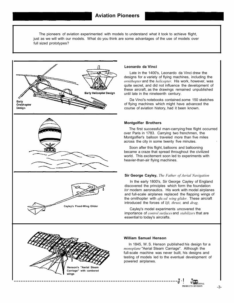
Aviation Pioneers
The pioneers of aviation experimented with models to understand what it took to achieve flight,
just as we will with our models. What do you think are some advantages of the use of models over
full sized prototypes?
Cayley's Fixed-Wing Glider
Leonardo da Vinci
Late in the 1400's, Leonardo da Vinci drew the designs for a variety of flying machines, including the ornithopter and the helicopter. His work, however, was
quite secret, and did not influence the development of these aircraft, as the drawings remained unpublished until late in the nineteenth century.
Da Vinci's notebooks contained.some 150 sketches of flying machines which might have advanced the course of aviation history, had it been known.
Montgolfier Brothers
The first successful man-carrying free flight occurred over Paris in 1783. Carrying two frenchmen, the Montgolfier's balloon traveled more than five miles across the city in some twenty five minutes. ·
Soon after this flight, balloons and ballooning became a craze that spread throughout the civilized world. This excitement soon led to experiments with heavier-than-air flying machines. Sir George Cayley, The Father of Aerial Navigation
In the early 1800's, Sir George Cayley of England
discovered the principles which form the foundation tor modern aeronautics. His work with model airplanes and full-scale airplanes replaced the flapping wings of the ornithopter with afu:ed wing glider. These aircraft
introduced the forces of lift, thrust, and drag.
Cayley's model experiments uncovered the importance of control surfaces and stabilizers that are essential to today's aircrafts.
William Samuel Henson
In 1845, W. S. Henson published his design for a monoplane "Aerial Steam Carriage". Although the
full-scale machine was never built, his designs and
testing of models led to the eventual development of powered airplanes.
Henson's "Aerial Steam
Carriage" with cambered
wings
-----------------------------------------------------------------------J-·! JrEDrUCoATIONAL
PRODUCTS DIVISION -3-

EDUCATIONAL PRODUCTS DIVISION -4-
DuTemple's design
shows a slight
dihedral In the
wings
One of Penaud's
"model
planophones"
Marey's
wind
tunnel
photography
Felix DuTemple
In 1857, DuTemple patented his design for the first airplane device that rose into the air under its own power (hot air). The design had been tested successfully with a scale model. His design included a tractor propeller, swept-forward wing and tail, and
retractable landing gear. Alphonse Penaud
In 1870, Alphonse Penaud began experimenting with model airplanes powered by twisted rubber bands. His model "planophones" had raised wing tips and a negatively positioned tail plane. Some even incorporated a vertical rudder which added stability.
A few years later, Penaud proposed using a new method of instantaneous photography to record the actions of birds' wings in flight. Entienne-Jules Marey
Late in the 1800's, Marey put Penaud's photography methods into practice. The resulting photographs allowed man to study the birds' motions of flight in great detail.
Later, Marey studied airflow by photographing the
smoke displaced in a wind tunnel by different shapes. These studies eventually led to the development of airfoil designs to create better lift.
Otto Lilienthal
By 1891, Lilienthal had built and flown the first of several successful gliders. In 1896, Lilienthal flew the
first hang glider himself, with movable wing tips that were powered by a small carbonic acid gas motor.
Lilienthal was the first person to study gliding flight scientifically, and is regarded as the "greatest pioneer" of the late 1800's. His successful manned flights inspired a great deal of future glider pilots, including Wilbur & Orville Wright.
Wilbur & Orville Wright
The Wright brothers began studying aviation in 1899. They built their first glider in 1900, and for several
years, they conducted test flights at Kitty Hawk.
Throughout these test flights, the Wright brothers
managed to control the pitch, the yaw and the roll of
their gliders. They went on to make the world's first powered, sustained and controlled airplane flight in 1903.
By 1905, they had built and flown the first practical flying machine which could be banked, turned and circled with ease. This plane, the "Flyer Ill", could fly for over half an hour.
•' !!1 I------------------------------------------------------------------------l
Why Do Airplanes Fly?
The same scientific principles apply to why a model airplane flies as they do to a full size
airplane. The same forces are at work upon each, and they must be managed in order to achieve
flight.
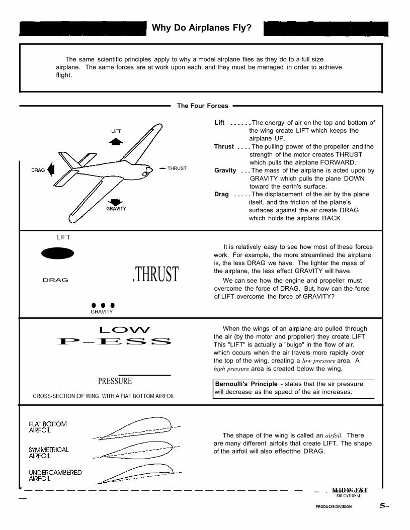
The Four Forces
LIFT
GRAVITY
•LIFT
•THRUST
Lift ......The energy of air on the top and bottom of
the wing create LIFT which keeps the
airplane UP.
Thrust ....The pulling power of the propeller and the
strength of the motor creates THRUST
which pulls the airplane FORWARD.
Gravity ...The mass of the airplane is acted upon by
GRAVITY which pulls the plane DOWN
toward the earth's surface.
Drag .....The displacement of the air by the plane
itself, and the friction of the plane's
surfaces against the air create DRAG
which holds the airplans BACK.
It is relatively easy to see how most of these forces
work. For example, the more streamlined the airplane
is, the less DRAG we have. The lighter the mass of
DRAG
... .THRUST
the airplane, the less effect GRAVITY will have.
We can see how the engine and propeller must
overcome the force of DRAG. But, how can the force
of LIFT overcome the force of GRAVITY?
GRAVITY
LOW
P-ESS
PRESSURE
CROSS-SECTION OF WING WITH A FIAT BOTTOM AIRFOIL
When the wings of an airplane are pulled through
the air (by the motor and propeller) they create LIFT.
This "LIFT" is actually a "bulge" in the flow of air,
which occurs when the air travels more rapidly over
the top of the wing, creating a low pressure area. A
high pressure area is created below the wing.
Bernoulli's Principle - states that the air pressure
will decrease as the speed of the air increases.
The shape of the wing is called an airfoil. There
are many different airfoils that create LIFT. The shape
of the airfoil will also effectthe DRAG.
'------------------------- -
-
'111111111 . MPRDIDDUCJWS COE., ISNCT.
EDUCATIONAL
PRODUCfS DIVISION 5-
The Importance of Control
EDUCATIONAL PRODUCTS DIVISION -6-
' '
-
So far, we have learned the basics of how to keep an aircraft UP in the air, and moving
FORWARD. Next, we must consider how to control the aircraft so that it is STABLE in its forward
flight, and capable of making controlled banks, turns, and circles. The control surfaces of an aircraft
allow this type of controlled movement.
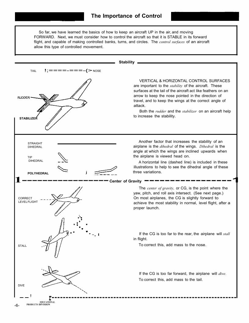
Stability
TAIL !;====-===-{> NOSE
STABILIZER
STRAIGHT
DIHEDRAL
TIP
DIHEDRAL
POLYHEDRAL
VERTICAL & HORIZONTAL CONTROL SURFACES
are important to the stability of the aircraft. These
surfaces at the tail of the aircraft act like feathers on an
arrow to keep the nose pointed in the direction of
travel, and to keep the wings at the correct angle of
attack.
Both the rudder and the stabilizer on an aircraft help
to increase the stability.
Another factor that increases the stability of an
airplane is the dihedral of the wings. Dihedral is the
angle at which the wings are inclined upwards when
the airplane is viewed head on.
A horizontal line (dashed line) is included in these
illustrations to help to see the dihedral angle of these
j three variations.
1----------------- Center of Gravity -----------------1 The center of gravity, or CG, is the point where the
yaw, pitch, and roll axis intersect. (See next page.)
CORRECT
LEVEL FLIGHT
STALL
DIVE
''•'
'''
''' / '' '' -,
On most airplanes, the CG is slightly forward to
achieve the most stability in normal, level flight, after a
proper launch.
If the CG is too far to the rear, the airplane will stall
in flight.
To correct this, add mass to the nose.
If the CG is too far forward, the airplane will dive.
To correct this, add mass to the tail.
--' r------------------------------------------------------------------
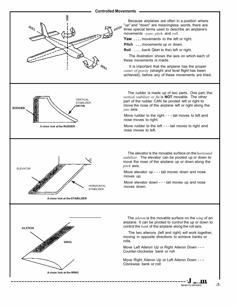
Controlled Movements
Because airplanes are often in a position where
"up" and "down" are meaningless words, there are three special terms used to describe an airplane's movements -yaw, pitch, and roll.
Yaw .... movements to the left or right.
Pitch ...movements up or down.
Roll ....bank Qean to the) left or right.
The illustration shows the axis on which each of these movements is made.
It is important that the airplane has the proper center of gravity (straight and level flight has been
achieved), before any of these movements are tried.
RUDDER
ELEVATOR
A closer look at the RUDDER
VERTICAL
STABILIZER
OR FIN
HORIZONTAL
STABILIZER
The rudder is made up of two parts. One part, the vertical stabilizer or fin is NOT movable. The other part of the rudder CAN be pivoted left or right to move the nose of the airplane left or right along the yaw axis.
Move rudder to the right - - - tail moves to left and nose moves to right.
Move rudder to the left - - - tail moves to right and nose moves to left.
The elevator is the movable surface on the horizontal
stabilizer. The elevator can be pivoted up or down to move the nose of the airplane up or down along the pitch axis.
Move elevator up - - - tail moves down and nose moves up.
Move elevator down - - - tail moves up and nose moves down.
A closer look at the STABILIZER
The aileron is the movable surface on the wing of an airplane. It can be pivoted to control the up or down to control the bank of the airplane along the roll axis.
The two ailerons (left and right) will work together, moving in opposite directions to achieve banks or rolls.
Move Left Aileron Up or Right Aileron Down - - - Counter-clockwise bank or roll
Move Right Aileron Up or Left Aileron Down - - - Clockwise bank or roll
A closer look at the WING
----------------------------------------------------------------·J E.DUCATmIONAL
PRODUCTS DIVISION -7-
Curriculum Enhancement Activities
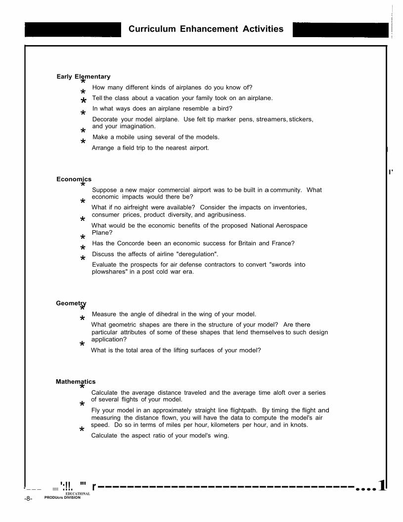
Early Elementary
* How many different kinds of airplanes do you know of?
* Tell the class about a vacation your family took on an airplane.
* In what ways does an airplane resemble a bird?
* Decorate your model airplane. Use felt tip marker pens, streamers, stickers, and your imagination.
* Make a mobile using several of the models.
* Arrange a field trip to the nearest airport. I
I' Economics
* Suppose a new major commercial airport was to be built in a community. What economic impacts would there be?
* What if no airfreight were available? Consider the impacts on inventories,
consumer prices, product diversity, and agribusiness.
* What would be the economic benefits of the proposed National Aerospace Plane?
* Has the Concorde been an economic success for Britain and France? i
* Discuss the affects of airline "deregulation".
* Evaluate the prospects for air defense contractors to convert "swords into plowshares" in a post cold war era.
Geometry
* Measure the angle of dihedral in the wing of your model.
* What geometric shapes are there in the structure of your model? Are there particular attributes of some of these shapes that lend themselves to such design application?
* What is the total area of the lifting surfaces of your model?
Mathematics
* Calculate the average distance traveled and the average time aloft over a series of several flights of your model.
* Fly your model in an approximately straight line flightpath. By timing the flight and
measuring the distance flown, you will have the data to compute the model's air speed. Do so in terms of miles per hour, kilometers per hour, and in knots.
* Calculate the aspect ratio of your model's wing.
'--- 1111 ':!!. "' r -----------------------------------....1 EDUCATIONAL
-8- PRODUcrs DIVISION
*
*
*
* * *
*
'
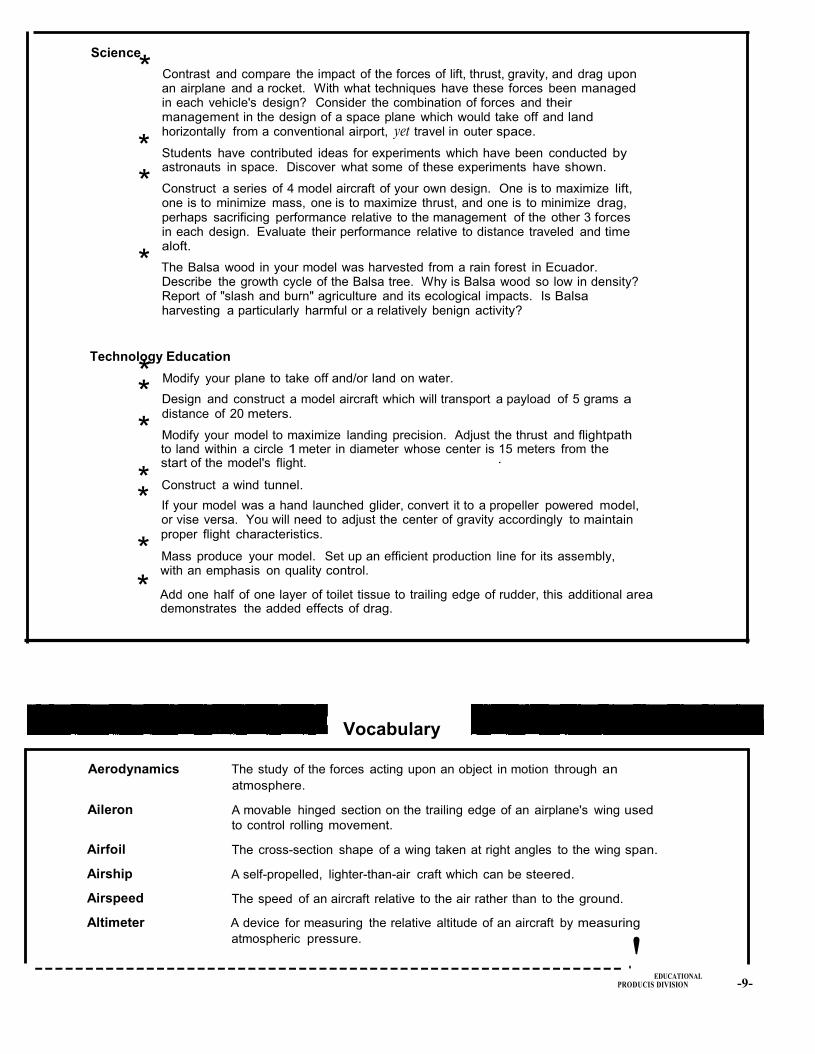
Science
Contrast and compare the impact of the forces of lift, thrust, gravity, and drag upon an airplane and a rocket. With what techniques have these forces been managed in each vehicle's design? Consider the combination of forces and their management in the design of a space plane which would take off and land horizontally from a conventional airport, yet travel in outer space.
* Students have contributed ideas for experiments which have been conducted by astronauts in space. Discover what some of these experiments have shown.
Construct a series of 4 model aircraft of your own design. One is to maximize lift, one is to minimize mass, one is to maximize thrust, and one is to minimize drag, perhaps sacrificing performance relative to the management of the other 3 forces in each design. Evaluate their performance relative to distance traveled and time aloft.
The Balsa wood in your model was harvested from a rain forest in Ecuador. Describe the growth cycle of the Balsa tree. Why is Balsa wood so low in density? Report of "slash and burn" agriculture and its ecological impacts. Is Balsa harvesting a particularly harmful or a relatively benign activity?
Technology Education
Modify your plane to take off and/or land on water.
Design and construct a model aircraft which will transport a payload of 5 grams a distance of 20 meters.
Modify your model to maximize landing precision. Adjust the thrust and flightpath to land within a circle 1 meter in diameter whose center is 15 meters from the start of the model's flight. ·
* Construct a wind tunnel.
* If your model was a hand launched glider, convert it to a propeller powered model, or vise versa. You will need to adjust the center of gravity accordingly to maintain proper flight characteristics.
Mass produce your model. Set up an efficient production line for its assembly, with an emphasis on quality control.
* Add one half of one layer of toilet tissue to trailing edge of rudder, this additional area demonstrates the added effects of drag.
Vocabulary
Aerodynamics The study of the forces acting upon an object in motion through an
atmosphere.
Aileron
Airfoil
Airship
Airspeed
Altimeter
A movable hinged section on the trailing edge of an airplane's wing used
to control rolling movement.
The cross-section shape of a wing taken at right angles to the wing span.
A self-propelled, lighter-than-air craft which can be steered.
The speed of an aircraft relative to the air rather than to the ground.
A device for measuring the relative altitude of an aircraft by measuring
atmospheric pressure.
----------------------------------------------------------· EDUCATIONAL
PRODUCIS DIVISION -9-

11111111 PRODUCTS CO.., INC.
Angle of Attack The angle at which a wing strikes the air stream.
Angle of Incidence The angle of the wing in relation to an arbitrary line fore and aft in the
fuselage.
Aspect Ratio The relationship of the wing span to the wing chord, expressed numerically
by the number oftimes the span can be divided by the chord.
Autogiro An airplane which flies by virtue of freewheeling rotating wings set
windmill fashion above the fuselage.
Bank A turn made in flight with one wing tip lower than the other.
Camber The curvature of the wing from the leading edge to the trailing edge.
Canard An airplane designed to fly tail first.
Center of Gravity The point through which the resultant forces of gravity act no matter how
the body is oriented.
Center of Lift The point at which the average of all lifting forces act.
Center of Pressure The intersection of the resultant force with the plane of the chord of the
lower surface. This center varies with the angle of incidence in a
characteristic manner for every wing shape. The center is located for a
given angle of incidence by giving its distance from the leading edge in
percent of the chord length.
Chord The width of a wing from leading edge to trailing edge.
Decalage The difference between the angles of incidence of the wing and the
stabilizer.
Dihedral The uptilt of wing panels toward the tips to increase stability in the roll
axis.
Elevator The hinged control section of the stabilizer used to induce a change in
pitch.
Fin The fixed forward portion of the vertical tail.
Fixture A form for holding parts together for assembly.
Fuselage The body of an airplane.
Glide Sustained forward flight in which speed is maintained only by the loss of
altitude.
Ground Speed The speed of an aircraft relative to ground.
Induced Drag The resistance of a wing to forward movement due to disturbance of the
surrounding air and related to the lift produced by the wing.
Mass The quantity of matter in a body.
Moment Arm The distance from the center of gravity at which a force is applied.
Motor Stick A strong wooden strip, often serving as a fuselage, used to support the
rubber motor of a model airplane.
.. .• MIDWEST----------------------------1 I'IUi\ EDUCATIONAL
-10- PRODUCTS DIVISION
liiUi\ EDUCATIONAL-
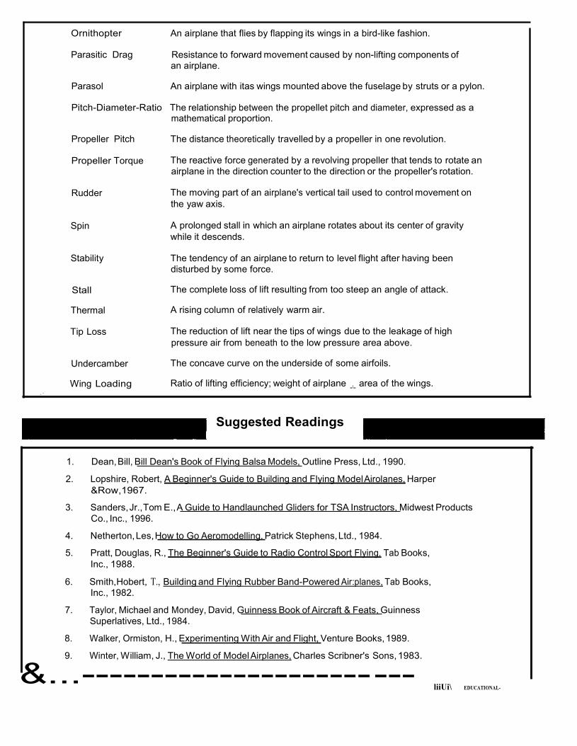
Ornithopter An airplane that flies by flapping its wings in a bird-like fashion.
Parasitic Drag Resistance to forward movement caused by non-lifting components of an airplane.
Parasol An airplane with itas wings mounted above the fuselage by struts or a pylon.
Pitch-Diameter-Ratio The relationship between the propellet pitch and diameter, expressed as a mathematical proportion.
Propeller Pitch The distance theoretically travelled by a propeller in one revolution.
Propeller Torque The reactive force generated by a revolving propeller that tends to rotate an airplane in the direction counter to the direction or the propeller's rotation.
Rudder The moving part of an airplane's vertical tail used to control movement on
the yaw axis.
Spin A prolonged stall in which an airplane rotates about its center of gravity
while it descends.
Stability The tendency of an airplane to return to level flight after having been disturbed by some force.
Stall The complete loss of lift resulting from too steep an angle of attack.
Thermal A rising column of relatively warm air.
Tip Loss The reduction of lift near the tips of wings due to the leakage of high
pressure air from beneath to the low pressure area above.
Undercamber The concave curve on the underside of some airfoils.
Wing Loading Ratio of lifting efficiency; weight of airplane _,_ area of the wings. .·
Suggested Readings
1. Dean, Bill, Bill Dean's Book of Flying Balsa Models, Outline Press, Ltd., 1990.
2. Lopshire, Robert, A Beginner's Guide to Building and Flying Model Airolanes, Harper
&Row,1967.
3. Sanders, Jr.,Tom E., A Guide to Handlaunched Gliders for TSA Instructors, Midwest Products
Co., Inc., 1996.
4. Netherton, Les, How to Go Aeromodelling. Patrick Stephens, Ltd., 1984.
5. Pratt, Douglas, R., The Beginner's Guide to Radio Control Sport Flying. Tab Books,
Inc., 1988.
6. Smith,Hobert, T., Building and Flying Rubber Band-Powered Air:planes, Tab Books, Inc., 1982.
7. Taylor, Michael and Mondey, David, Guinness Book of Aircraft & Feats, Guinness
Superlatives, Ltd., 1984.
8. Walker, Ormiston, H., Experimenting With Air and Flight, Venture Books, 1989.
9. Winter, William, J., The World of Model Airplanes, Charles Scribner's Sons, 1983.
&...--------------------- ---
15 © University of Colorado Colorado Springs, Center for STEM Education. Creative Commons License (by-nc-sa), 2011. Curriculum creation funded by Air Force Office of Scientific Research (AFOSR). Curriculum format design adapted from CDIO developed by Massachusetts Institute of Technology (MIT).