Embed Size (px)
Citation preview

Indian Railway Signal
Engineering
Volume – II &
Volume – III
By: Pramod P. Goel

Indian Railway Signal
Engineering
Volume –II &III
By
Pramod P. Goel BSc, MBA, Member IETE Former DYCSTE/CORE
(E-mail: [email protected])
2012
Published by:
Astha Publications F-8, Panch Puspa Apartments
Ashok Nagar, Allahabad-211001
Phone: 919935667116
Distributors:
Bahri Brothers 743, Lajpat Rai Market, Delhi-110006.
Phones:23861740 & 23866291.

© Pramod P. Goel Other Books by the same author:
Already published: 1. First and Fourth volumes of Indian Railway Signal Engineering: Out of first and fourth volumes already published, the first volume was published in June 2008 running in 145 pages covered in six chapters and 72 illustrative diagrams. The book provides history of signalling, all about rules concerned with signals, System of working trains, Signal Engineering Manual, Rules for Opening Railways for Public Carriage of Passengers, Schedule of Standard Dimensions related to signalling system, effect of Electric traction on signalling and much more information which one shall like to keep handy. The fourth volume of the book, in 347 pages covered under nine chapters with 204 illustrative diagrams, is designed to provide electrical system of operating devices, operated equipment, transmission media, electrical system of interlocking, Electronic Interlocking, Monitoring devices, Power supply for signalling system, Block working systems, and many more developments in signalling system for improved safety, prevalent on Indian Railways, besides Moving Block yet to take place in India. Besides, all the four volumes of Indian Railway Signal Engineering are designed to be ready reckoner for the signal engineers available compacted at one place useful in day-to-day practice for Signal Engineers, as well as it shall equally be helpful in preparation for departmental examinations for signal as well as telecommunication engineers. 2. Tenders, contracts and Arbitration: Book running in V chapters, covers the laws applicable to contracts, Arbitration Act, preparation of tender documents, methods and new methods of evaluation of tenders, process of entering into contracts, dos and don’ts for tender committee, Project Management Consultancy contracts, dealing with vigilance, some tips. 3. Under publication: Electronic Interlocking: By: S.C. Mishra and Pramod P. Goel Books available on web site www.thegoelassociates.com
Printed by:
Amar Mudralalay 15/1/7 – Katra Madho Kunj,
Allahabad-211002
Published: April’ 2012.
Price: Export Edition
In India : Rs. 395.00 Out side India : $ 45 USD.

Dedicated to my parents

i
INTRODUCTION
The author had decided to bring the subject of Indian Railway Signal Engineering in four volumes with an intention to cover each subject in detail while at the same time for keeping the book wieldy & choice worthy. Accordingly first volume of the book was published in June’ 2008. Under consideration of fast emerging system of Electrical and Electronic based system of Signal Interlocking, he took up the book on this subject, published in January’ 2010. In the mean time he was suggested by Shri Mahabir Prasad the then Additional Member Railway Board to take up the subject of tenders and contracts with emphasis on the subject of arbitration & vigilance. The opportunity was availed and the book on Tenders Contracts and Arbitration was published in September’2011. Just around the same time, while the author got an opportunity to talk to Shri Arvind Mittal, Dean Faculty, IRISET, who suggested combining the pending Volumes-II & III of Indian Railway Signal Engineering in one cover which appealed to me and accordingly the book in your hand covers both the volumes. Volume-II: Subject of Planning & Designing of Indian Railway Signal Engineering is not available anywhere outside the drawing offices of the associated Headquarters and Divisional and Extra Divisional offices. Each Railway is following its own practice and many a times officers joining railways on transfer from one to other, also influence the practices of the railway from which they come, causing a heterogeneous mix of style and practice of planning & designing. It is therefore proposed to implement only one policy over Indian Railways for design of signalling system at least so far as interlocking practices are concerned. Signal engineering is covered in Volume-I, Volume-III & Volume-IV, while Planning & Designing (P&D) of signalling systems has been put under Volume-II. The importance of organised system of Planning & Designing is so much so that each railway has an independent wing of planning & designing headed by the Chief Signal & Telecommunication Engineer (P&D) reporting to the Principal Chief Signal & Telecommunication Engineer. Accordingly the subject covers key points of the Planning & Designing necessitating preparation of about twenty plans. Accordingly Volume-II of the book covers almost everything possible to know about the all possible systems compelling me to mention preliminary information in the form of references available in details from the other three volumes. Besides some topics not already appearing in other volumes such as survey for sighting cabins, cable route plan, Station Working Rule diagram and Station Working Rules based on Railway Board’s directives, have been provided. Plans as required to be prepared for bringing a signalling installation to an organised system, before putting in use, it is of utmost importance for the signal engineer to be fully acquainted of purpose, utility and provision of information in each such plan. Since Planning and designing is the sum total of entire signalling system covered under other three volumes, references beyond the material specific to this book are made wherever required. However some incidences call for to be repeated for immediate usage to maintain

ii
continuity for the reader, does result in unavoidable duplication. The book being plan oriented as such it covers 47 major drawings, 11 tables and 22 plans. Volume-III: About 60%-70% of 7000 stations on Indian Railways, working with mechanical and electro mechanical system of Interlocking, are being replaced with electrical/electronic interlocking, which is going to take time. Accordingly the technology is very much in use and is required for maintenance and replacement at least, which cannot be thrown back into history. It is pertinent to note that while introducing 25KV AC traction, even today colour light signalling is being provided replacing mechanical signals but retaining levers, lever frames and mechanical interlocking, by Railway Electrification under Ambala project of Northern Railway. Keeping this in mind mechanical system of signalling has been covered in two sections, first being ‘Single Wire’ and second ‘Double Wire’, covered under Volume-III, presented in two sections. The Section-I of the book covers Single Wire system of signalling and Section-II, Double Wire system of signalling. This book, basically, deals with broad gauge railways which covers the major portion of Indian Railways. So far as basic data is concerned help has been taken from IRISET notes on the subject accordingly the dimensions have been mentioned in FPS as well as MKS System. In many cases the equivalent corresponding MKS version of the dimensions in FPS may not be found in exact consonance to suite technical requirements of manufacturing. The book covers 82 major drawings & diagrams of components used for single and double wire system of signalling. Combined volumes-II & III: Accordingly the Volume-II & III, of Indian Railway Signal Engineering, the book in your hand stands supplemented by other volumes i.e. Indian Railway Signal Engineering Volume-I and Volume-IV, authored by the same author and as such has to be read along with these volumes. Traversing across these two books: While numbering the text, first digit of each paragraph indicates the number of chapter, second digit is the number of the main paragraph, third digit is the sub number of main paragraph and the fourth is the sub-number of sub-paragraph. Other alphanumeric numbers are sub-numbers down below. It is pertinent to note that with the conversion from FPS to MKS, the of dimensions of equipments have not been converted to exact equivalent of FPS version but have been changed to convenient and practicable sizes, resulting in total mismatch of parts between sizes under two systems of measurement. This makes it extremely important to abide to follow the latest system in use. Accordingly MKS system of measurement has been mentioned first and corresponding FPS measurements within brackets. In some cases FPS system of measurements has been used in notes issued by IRISET, which has been adopted as it is. The author does not know the extent to which the effort made, have been successful; as such your observations and suggestions for its improvement shall be his privilege.

iii
ACKNOWLEDGEMENTS The author expresses his sincere gratitude to Shri A.K. Misra, Additional Member (Telecommunication), Railway Board, for taking keen interest in going through the book ‘Indian Railway Signal Engineering’ (Volume-II & III) and writing the forward. The Author is equally indebted to Shri M. Suresh, Additional Member (Signal), Railway Board, who, besides having gone through the book, also discussed various aspects and wrote commendable Forward. This book is the result of persistent encouragement of Shri Madan Mohan Agarwal, Ex Chief Engineer, Northern Railway and renowned author of books on the subject of Railway Track Engineering. I am not hesitant to record that the book in your hands might not have seen the light of the day had it not been his inspiration. The author expresses his sincere thanks to Shri Aggarwal. The author is highly obliged to Shri P.K. Srivastava, now the Principal CSTE/SCR, who gave recognition and appreciation to the Volume-I & III of the book Indian Railway Signal Engineering, along with the book on Tenders Contracts and Arbitration, Shri Raman Lal Gupta the then Director, IRISET, for granting recognition to the books on Indian Railway Signal Engineering Volume-IV & Tenders Contracts and Arbitration for the library of IRISET, Shri Mahesh Mehta, Principal CSTE, Jaipur who took interest in work done and spending time on discussion on the subject with him and decided to procure books for the library, Shri Anand Kumar, Principal CSTE, NCR, Allahabad who gave his time and listened and appreciated the work done and decided to procure books for the library. Shri Akhil Agrawal, Principal CSTE, Northern Railway, who while acknowledging the utility of the book, decided to add it to the N.R. library. He is extremely thankful to, Shri S.P. Upadhyay, the then CSTE Planning NCR for taking keen interest and appreciating the books. He is also thankful to Shri Prosun Banerjee, the then CSTE (P&D) CORE, Allahabad and also to Shri Alok Chaturvedi CSTE (P&D) CORE, Allahabad, for their recognition and appreciation of the books content. He is highly obliged to Shri Arvind Mittal, Dean Faculty, IRISET for not only for supporting him but also being thoughtful in advising to club both the volumes into one. He is obliged to Shri P.L. Srivastava, Ex SSTE/CORE who having gone through the text of both the volumes painstakingly has not only been instrumental for many corrections but also has given very valuable suggestions. He is equally obliged to Shri Amit Kumar Kesarwani, (BCA), Design Engineer of the firm, ‘The Goel Associates’, who has not only prepared number of technical drawings for the book, on CAD, but also has taken pains to read and organise text of both the book in hand. He expresses his sincere thanks to Shri Sidhu Yadav, SSTE Planning & Designing, North Central Railway, Allahabad, and Shri K.R. Verma (ex) SSTE/CORE, for helping with the latest

iv
prevalent practices of Railways and for extending support in providing information required for the book. It would not have been possible for him to work on this book without active support from his wife Pratibha Goel and all my family members, my son-in law Amitabh Singhal, daughter Chhavi Singhal, son Dr. Vaibhava Goel, Daughter-in law Sumedha Goel, son Vipul Goel and daughter-in-law, Nimita Goel, who have not only extended moral support but also have been giving help and advice also to enable me reach to this point. At this juncture, the author remembers his parents, late Ved Prakash & Praksh Vati, but for whose blessings and his uncle, late Arya Bhushan, for whose guidance, the author could not have reached to this point where he is.
PRAMOD P. GOEL Allahabad Date: April’ 2012 Phone: 9415237899 [email protected]
*****

v
CONTENTS
Indian Railway Signal Engineering Volume - II
Chapter Page Number
I BASIS FOR PLANNING OF SIGNALLING SYSTEM 1-8
1.0 Planning of signalling system; Factors required to be well understood before taking
up planning. 1.1 System of working trains proposed to be used; Absolute Block System; Automatic
Block System; Intermediate Block Signalling system. 1.2 Type of traction in use or proposed to be used. 1.3 Engineering Scale Plan; ESP, the basic plan with minute details of the yard; Type of
turnouts provided; Permissible speed on turnouts. 1.4 Classification of the station; Conditions for granting Line clear at a class ‘A’ station;
Conditions for granting Line Clear at a class ‘B’ station on double line; Conditions for granting Line Clear at a class ‘C’ station; Block Huts; Non-Block stations or Class ‘D’.
1.5 Train traffic density, block section and direction of traffic; Train traffic density; Block section and direction of traffic; twin single lines; Station Section.
1.6 Signalling system at station yard or block section; Within station Section; Within Block section.
II PLANNING OF SIGNALLING SYSTEM 9-49 2.0 Signalling System. 2.1 Features of the section in which the signalling is to be planned, Commercial and
political factors. 2.2 The sanctioned speed; Commercial and political importance of the section; Technical
factors. 2.3 Section capacity; Single or double line; Overlap considerations; Block overlap; Signal
overlap; Granting of Line clear; Intermediate Block Signalling. 2.4 Gradients in and around the station section. 2.5 Hot axle siding. 2.6 Essentials of Interlocking. 2.7 Standards of Interlocking; Type of Interlocking and signalling system; Standards of
Interlocking; Standard – I Interlocking; Standard – II Interlocking; Standard – III Interlocking; Standard – IV Interlocking.
2.8 Type of signalling to be provided at the station section. 2.9 Systems of signalling; Single wire system of signalling; Levers, lever frames and
interlocking – Single wire system of signalling; Lever frame of single wire signalling system; Interlocking-direct locking type; Lever frame & locking box - Direct locking type; Catch Handle type/1924 type of lever frame; Lever-lock; Transmission-Single wire; Transmission-rod run; Double wire system of signalling, operating devices and transmission; Double wire system of signalling; levers, Lever frame; Operation of Signals by double wire; Operation of Points by Double Wire; Transmission and

vi
Double wire compensators; Interlocking for double wire; Hybrid arrangement of Mechanical interlocking supplemented by electrical interlocking.
2.10 Power frame. 2.11 Ground lever frames. 2.12 System of Electrical Signalling; System of Electrical Signalling with electrical
interlocking; Operation by Control cum indication panel; Non-route setting type system of operation; Route setting type system of operation; Push buttons; Indications; Counters; Route relay Interlocking (RRI); System of Electrical signalling with Electronic Interlocking; Control cum Indication Panel or VDU.
2.13 Route holding, approach and back locking, track locking, lock bar, fouling and clearance bars; mechanical system of signalling, the approach locking is left to the Cabin Master’s discretion; back locking; track locking; fouling bar; clearance bar; Flank Protection. Electrical interlocking.
2.14 Effects of traction used in the section for train haulage; Diesel Engines (diesel traction): Electric traction; DC traction; 25 KV AC traction; Effect of traction and loco on Clear Available Length (CAL); Accommodation for berthing of train; Loco factor; Electric traction; Diesel driven traction; Point is operated mechanically.
2.15 Safety features; Correspondence between operating devises and the operated equipment; Correspondence between control and operation of point; Correspondence between control and operation of signals; Monitoring track vacancy, of a given section of the track; DC track circuit; AC track circuits; AC track circuits with uneven
pulse; Audio Frequency Track Circuit (AFTC); Axle counters; Advantages of using axle counters; Disadvantages; Purpose of track vacancy monitoring; Device to monitor the signalling system-data logger; Anti Collision Devices; Automatic Warning System (AWS); Train Protection & Warning System (TP & WS); Raksha Kavach; Train Actuated Warning Device for level crossing gates (TAWD).
2.16 Rail insulation of the track; type of sleepers provided in the station yard and the block section; Type of sleepers and selection of track circuits to be provided in the station yard; Type of sleepers and selection of track circuits to be provided in the block section.
2.17 Block working; Specified space; Absolute Block System of train working; Double line section; Single line section; Double line section; Single line section; Intermediate Block System of train working; Automatic Block signalling; Semiautomatic signals.
2.18 Power supply requirements for signalling system & communication; Integrated Power Supply (IPS); Solar Panel.
2.19 Deciding Location for controlling the signalling system; system of single wire signalling; system of double wire signalling; Sighting of cabins if required, to suit the system of signalling; Single wire system of operating; Double wire system of operating; Operation of colour light signals; along with electrical interlocking; with electronic interlocking.
2. 20 Site survey for placement and size of the cabins; Last vehicle check; Watching & monitoring running train for any abnormality; Deciding location of cabin: With reference to signals, points and level crossing gates, operated by cabin; Goomty; Schedule of dimensions and accommodation of lead-outs; Size of the cabin to accommodate lever frame; Central operation; Station Master’s (SM’s) room.

vii
2.21 Operated equipment; Signal; Calling-on signal; Shunt signal; Point; Level crossing gate; Interlocked Level crossing gate falling within station limits; Interlocked Level crossing falling within station section; Interlocked Level crossing gate falling in Absolute block section; Interlocked Level crossing gate falling in Automatic block section; Operation of interlocked level crossing gates; Level crossing gate operated through mechanical means; gate is provided within station section; gate in the block section; Power operated lifting barrier gate.
2.22 Sidings in station section & block section; Sidings in station section; Stabling siding; private/Trap siding; Stabling siding for holding train racks; Washing line siding; Long siding to be kept clear to be used as overlap; Siding for shunting purposes; Goods wharf; Direct reception and dispatch to & from a siding is not allowed; Siding taking Off from the block section; Catch siding; Slip siding.
2.23 Communication; Communication between Station Master and staff posted in cabins and level crossing gates, under his control; Communication between Cabin Master & Level crossing gate; Communication between Section controllers and Station Masters
throughout under the jurisdiction of the concerned section controller; Mobile communication; (GSM-R) or GSM-Railway.
III DOCUMENTATION AND SANCTION OF COMMISSIONER OF RAILWAY
SAFETY 50-54
3.0 Commissioner of Railway Safety. 3.1 Legal authorisation. 3.2 Notification before opening of works. 3.3 Approved plans, drawings and specifications. 3.4 Commencement of the work; Plans & drawings; CRS’s sanction; Documents. 3.5 Works requiring sanction of Commissioner of Railway Safety. 3.6 Application to the Commissioner of Railway Safety for obtaining sanction for
opening of the work. 3.7 Documents to be submitted to CRS with the application for opening of work; New
lines and Electrification; Signalling and Interlocking works; Tabulated details; Drawings of works; List of questions and answers; Station Working Rules; List of deviations; Introduction of new types of locomotives or rolling stock for increasing speed.
3.8 Basis and details for preparation of Station Working Rules; Basis for preparation of Station Working Rules; Details of preparation of Station Working Rules.
IV DESIGNING & DRAWING 55-124
4.0 Designing of signalling system. 4.1 Plans and drawings to be prepared in case of each type of signalling system; Plans
and drawings required for planning and designing of signalling system; Basic information to be born on each drawing prepared.
4.2 Signal and Interlocking plan; Signal and Interlocking Plan based on purpose; Tentative plan for the purpose of preparation of estimate; Tentative plan to be attached with the tender documents; Tentative plan to Division for comments;

viii
Information to be provided in the SIP; Preparation of SIP; Major information; Semaphore Signalling; Colour Light Signals; Numbering of the operated equipments on the SIP; Numbering on the SIP of the equipments operated by the single wire; Requirements out of special features of lever frame and lead out; Geographical system of numbering of equipment operated by single cabin; Numbering of equipment operated, for electrical system of signalling controlled by Central Panel or VDU; Geographical system of numbering of equipment operated by single cabin but yard split into two; Geographical system of numbering of equipment operated by end cabins; Numbering of levers for the Double Wire operated equipments; Numbering practices of track circuits: Numbering of track circuits based upon signal, point, and independent area; other method of numbering of the track circuits.
4.3 Station Working Rule Diagram; Preparation of Station working Rule diagram. 4.4 Panel Diagram; Preparation of Panel diagram. 4.5 Interlocking Table; Preparation of Interlocking Table; Standard columns of
Interlocking table: Number; Released By; Locks Normal; Locks Either Ways; Releases; Locking one way; Locking both ways in; Basic principles for preparation of interlocking table: Economy; Redundancy; Conflicting signals; Directly opposite signals; Conditional or Special Locking; Special notes on SIP; Latest and existing rules; Preparation of Interlocking table by Square sheet method: Structures & features of the square sheet; Principles of filling interlocking relationship; horizontal cancellation; Vertical cancellation; Filling in interlocking relations in the square sheet; Cancellation to eliminate redundant interlocking; Horizontal cancellation; Vertical cancellation; Special cancellation; Example of filling the square sheet and horizontal, vertical and special cancellations; Filling the square sheet; Horizontal cancellations; Vertical cancellations; Special cancellations; Entering data into Interlocking table; Preparation of Interlocking table by route method; Preparation of Interlocking Table for double wire lever frame; Tripping of the Rope drum; Tight & loose locking; Tight locking; Loose locking; Push-pull & pull-pull coupled levers; Push-Pull coupling; Pull-Pull coupling.
4.6 Interlocking Chart & its preparation; Preparation of Interlocking Chart for single wire system of interlocking Direct type of lever frame; Direct locking type lever frame & feature of Conflicting notches; In case of direct locking type lever frame; Preparation of Interlocking Chart for single wire system with Catch Handle type of Interlocking; In case of catch handle type lever frame; Preparation of Interlocking Chart for Double wire System of signalling.
4.7 Selection Table/Route Control Table. 4.8 Route Section Plan; Preparation of Route Section Plan. 4.9 Cable Route Plan; Deciding positions of apparatus cases and junction boxes;
Placement of the apparatus cases: Signal; Crank Handle; Housing relays; In case of axle counters; In case of points; In case of DC track circuits; Audio-frequency track circuits; It is pertinent to note; Site survey and preparation of cable route plan; existing cable route plan shall be procured from the record of maintenance organisation of railways; Trench shall be within railway boundary; Minimum depth of the trench; Trench in area electrified to 25 KV AC traction; Foot by foot survey.
4.10 Cable Core Allocation Plan; Assessment of the cable; Allocation of the cables;

ix
Preparation of cable Core Allocation plan. 4.11 Cable Core Termination Chart; Preparation of Cable Termination Chart; Cable Core
Allocation Plan so designed shall be made out in the form of a chart. 4.12 Main Distribution Frame; Cable Termination Rack; Terminals and Fuses; Composite
Rack; Main Distribution Frame; Power supply distribution; Cable Termination; Cable Termination Rack; Composite Rack.
4.13 Terminal and the connection; Practice of using the terminals horizontal and vertical; Terminals used with Electronic Interlocking; Tag Blocks used for Wiring Siemens Designed Circuits.
4.14 Fuses and Micro Circuit Breakers; Depiction of the positive and negative ends of power supply on the wiring diagram.
4.15 Track Circuit Allocation plan; Preparation of Track Circuit Allocation Plan Track Circuit Allocation Plan for DC & AC track circuits; Track Circuit Allocation Plan for Audio Frequency Track Circuit; Track Circuit Allocation Plan for Axle Counters; Analogue; Digital Axle counters: Single Section Digital Axle Counters; Multi Section Digital Axle Counters.
4.16 Track bonding plan. 4.17 Rod Compensation plan. 4.18 Apparatus Case wiring diagram. 4.19 Interlocking Wiring Diagram; Preparation of Interlocking Wiring Diagram; Relay
Rack Chart for ‘Q’ series relays; Contact Analysis for ‘Q’ series relays; Fundamentals of preparation of Contact analysis; It is pertinent to note; Fuse analysis & negative/neutral limb; Conversion of Interlocking Circuits into Wiring Diagram.
4.20 Termination & Tag Charts; Termination Chart; Tag Chart; Wire Count Chart. 4.21 Electronic Interlocking; Logic Circuits & Boolean equations. 4.22 Interface Circuits, Bit Chart and preparation; Interface Circuits; Preparation of
Interface circuits; Bit Chart; Room floor plan for EI equipment and power supply; System Rack Layout; System configuration plan; Card file layout; 12 Slot Keying Plug Female Connector; I/O Jumper settings & Address circuits; Jumper settings of the Address select PCBs; CPU, EEPROM & Power Supply connections; CPU board jumper settings; Serial Communication circuits; Master-Slave serial CPU Port Communication Circuits; Maintenance Personal Computer Diagnostic Serial Communication circuits; Data logger Serial Communication circuits; CPU Clock Supply circuits; Operator PC-1, Serial Communication circuits; Data Logger & Maintenance PC Communication circuits; Circuits for operation of outside equipment; Circuits for different power supplies for the system; Rack Termination Chart; Contact analysis.
4.23 Test Records; Track Circuit Test card; Cable core insulation chart; Earth Leakage Detector; Equipment Disposition and Power Supply Allocation plan; Equipment Disposition plan; Equipment Disposition for Mechanical signalling; Introduction of Railway Electrification; Equipment Disposition for panel operated signalling system; Equipment Disposition for Electronic Interlocking system; Power supply allocation plan; Power supply allocation for Integrated Power Supply system; Power supply allocation for Solar Power system.

x
APPENDICES 125-143
Appendix-I Section 20; Indian Railway Act. Appendix-II Application to CRS for sanction to execute the work.
Appendix-III Format for Safety certificate and Safety certificate for S&T works for
introducing electrification.
Appendix-IV Station Machinery. Appendix-V List of questions for answers for opening of New Lines or Electrification. Appendix-VI Joint Safety Certificate; In case of introduction of new type of locomotive. Appendix-VII Rules for sanction of opening of new railways. Appendix-VIII List of Infringements of maximum and minimum dimensions. Appendix-IX Symbols used for preparation of SIP. Appendix-X Track circuit record cards: for DC track circuits, Card Number S&T/TC-1. Appendix-XI Track circuit record cards: for AC Track circuits, Card number S&T/TC-2. Appendix-XII Track circuit record cards: for Jeumont Track circuits, Card number
S&T/TC-3. Appendix-XIII Cable insulation Resistance test sheet Main/Tail cables.
*****

xi
Indian Railway Signal Engineering Volume – III
SECTION – I: SYSTEM OF MECHANICAL SIGNALLING (SINGLE WIRE)
Chapter Page Number I SYSTEM OF MECHANICAL SIGNALLING & SINGLE WIRE SYSTEM
OPERATING DEVICES: DIRECT LEVER LOCKING INTERLOCKING
FRAME 2-14 1.0 System of mechanical signalling. 1.1 Direct lever locking interlocking frame; Lever; Slackness permissibility; Quadrants;
Standard; Lever shoe; Tail; Front Tail; Back Weight; Back Tail; Shaft; Interlocking Arrangement; Locking Plunger; Locking boxes; Locks; Conflicting notches and Interlocking; Diamond; Numbering of the channels; Security of Interlocking against unauthorised interference; Locks of sorts; Interlocking Bars..
1.2 Ground lever frame; Main parts of the Ground Lever Frame; Number Plate; Standard & Tie Rods; Shaft & Shaft Caps; Quadrants; Lever Shoe & front tail; Plunger; Lever; Catch Handle; Catch Rod; Catch Box; Locking Box; Fixing of ground lever frame.
1.3 Use of Double wire system for operating distantly placed signals; Use of Double wire levers on Catch Handle locking Interlocking frame; Mix of double wire system with Direct Interlocking lever;
II SINGLE WIRE SYSTEM OPERATING DEVICES: CATCH HANDLE
LOCKING TYPE INTERLOCKING FRAME 15-21 2.0 Catch Handle locking interlocking frame. 2.1 Main parts of the Interlocking frame; Lever; Slackness permissibility; Catch Handle;
Standard; Quadrants; Quadrant Supports; Lever Shoe; Shaft; Interlocking Arrangement; Locking boxes; Locking Plunger; Actuation of the Locking Plunger; Locks of sorts & Interlocking; Interlocking bars; Numbering of the channels; Security of Interlocking against unauthorised interference.
III TRANSMISSION 22-43 3.0 Media of transmission; Wire run; Rod run. 3.1 Lead-out; Lead-out Plates; Channel Iron Lead-out; Inside Lead-out; Inside Lead-out
for wire run; Inside Lead-out for Rod run; Out side Lead-out; Outside Lead-out for wire run; Outside Lead-out for rod run.
3.2 Wire Run; Wire; Joining of Wires; GI wire; 7 x 7 wire rope; Pulley Stakes and Wire Pulleys; Pulley Stakes; Wire Pulleys; Change of Direction of the Wire Run; Change of direction; Wire run crossing under the track and across Lever crossing; Passing the wire run across level crossing gate; Wire to detectors; Termination of wire on signal post; Precautions while laying wire run; Cabin wire adjuster.
3.3 Rod run; Rod; Tubular rod; Solid Rod; Rod joints; Eye joint; Joint flush; Long Joint; Joint Solid; Joint wide; Point adjusting screw; Joint Screw; Lug eye; Swan neck or

xii
Goose neck; Point rod coupling; Trestle & Standard Roller Guide; Trestle; Standard Roller Guide; Change of Direction of the Rod run; Straight arm crank; Relief Crank;
Rod passing under track and level crossing gate; Pass under the track; Pass through level crossing road; Rod compensation; Rod Compensator; Rod compensation plan; Rod compensation plan, Effective length; Equal arm right angle crank; Unequal arms right angle crank; Rod Compensation plan Condition, Unequal arm right angle crank; Rod Compensation plan Condition, equal arm right angle crank connected reversed; Rod Compensation plan Condition, Effective length of the rod; Termination of rod run; Adjustable crank; Creep; Throw rod; Adjustable straight arm crank; Operation of points; Uneven arm crank; Lock Bar/Holding Bar; Facing Point Lock; Process of smith welding at site; Maximum permissible limits for point operation; Rod worked points from single wire lever frame operated by single wire lever; Rod worked points from single wire lever frame operated by Double wire lever.
IV SIGNALS 44-53
4.0 Signals. 4.1 Signal fittings; Signal post Tubular; Cast Iron Signal Base; Signal post Lattice;
Bracket Signal Main Posts; Bracket Signal Posts; Dolls; Channel iron Bracket Main Signal Post; Lattice Bracket Main Signal Post; Tubular Bracket Signal Main Post; Boom; Lattice and Tubular Bracket Signal main Posts; Signal Gantry; Pinnacle; Ladder & Ladder foundation; Semaphore signal fittings; Semaphore fittings type ‘A’; Semaphore Spectacle; Semaphore Bracket; For tubular post; For lattice post a rectangular cast iron Bracket; Down Rod; back of Spectacle; Counter Weight Lever; Counter Weight Bracket; Signal Arm; ‘A1’ type signal arm; ‘A2’ type signal arm; Signal Lamp & Lamp Bracket; Back Light Screen; Semaphore fittings type ‘B’; Semaphore Spectacle; Semaphore Bearing; tubular post; Lamp Bracket; Lattice post; Signal Lamp & Lamp Bracket; lattice post; Stop; tubular post; Lattice post; Down Rod; Counter Weight Lever; Counter Weight Bracket; lattice post; tubular post; Signal Arm; ‘B1’ type signal arm; ‘B2’ type signal arm; Back Light Screen.
V MONITORING, LOCKING & SAFETY DEVICES 54-70
5.0 Monitoring, Locking & Safety Devices. 5.1 Correspondences between operating device and the operated equipment &
compliance to required norms. 5.2 Point & Turnout; Crossover. 5.3 Point Detector; Checking correspondence. 5.4 Facing point lock; Facing Point Lock without plunger travel detection; Facing Point
Lock with plunger travel and detection; Economical Facing Point Lock; 5.5 Stretcher Bar; 5.6 Correspondence of Signal with lever. 5.7 Lock Bar; Driving Attachment; Lock Bar Clip; Bracket; Link; Rocker Arm;
Extended Bracket; Flange Connecting Rod; Driving Attachment; area with the check rail; Holding bar; Fouling bar; Clearance bar.
5.8 Compliance of operation to required norms.

xiii
5.9 Monitoring devices. 5.10 Holding of the route until train reaches to the destination. 5.11 Interlocking through Key Plunger & E-Type Lock; Interlocking through Key; E-Type
Key lock; Key lock Facing Point H.P. Type; Hand Plunger Lock; Key Lock facing Points, Hand plunger type one way; Key Lock facing Points, Hand plunger type Double; Fixing the E-Type lock on the Lever in lever frame; Key Lock facing Points, Hand plunger type Treble & Quadruple.
5.12 E-Type Key Lock. 5.13 Mechanically operated lifting barriers; Winch; Lifting Barrier; Pedestal; Boom;
Trunnion Bracket; Auxiliary Weight and Balancing Weight; Boom Stand with Boom Lock.
SECTION – II: SYSTEM OF MECHANICAL SIGNALLING (DOUBLE WIRE)
I OPERATING DEVICES 72-88
1.0 The system of double wire signalling. 1.1 Levers and Lever Frame; Lever; Direct type lever; Lever; Lever Handle & Rope
Drum; Lever, Catch handle, Link and Latch Rod; catch handle; Link; Latch Rod; Crank; Standard and mounting of the Lever; Rope Drum; Clutch type lever; Lever handle; Catch handle; Link and Latch rod; Link rod; Latch Rod; Rope Drum; Clutch; Spring and Tripping; Tripped; Tripping of the Rope drum; tripping does not take place; Rope Drum trips; conditions arise for Tripping; Resetting of the Rope drum; Auxiliary Lever; Standard, crank, Main axle and Crank axle; Number plate with fault indicator; Three-to-One lever; Effect of tripping on Interlocking arrangements; Rack & pinion Lever; Major parts of the Rack & Pinion lever; Standard Roller; Rack; Pinion; Crank; Crank Axle; Lever Handle; Pinion Disk; Catch Handle; Catch Rod; Spring; Latch Rod; Catch Box; Coupling end; Miniature Lever; Two position type miniature lever; Three position type miniature lever.
1.2 Lever Frame & Interlocking Arrangements; Interlocking Arrangements; Locking box 1.3 Coupling of levers; Pull-Pull coupling of levers; Push-Pull coupling of levers;
Coupling arrangement; Push-Pull Coupling arrangement; Pull-Pull Coupling arrangement; Lever Drum Lock.
II TRANSMISSION & DEVICES 89-108
2.0 Transmission & Devices. 2.1 Wire & Wire Run; Wire used for transmission; Wire Rope 6 x 19 ¼; Solid steel
Galvanised Signal wire of 10 SWG, 8 SWG & 6 SWG; Joining of Wires; Wire Run. 2.2. Double Wire Compensator & formation of Loop; Major parts of the Double wire
compensator; It is pertinent to note; Ratchet rod; Locking Stroke. 2.3 Type of Double Wire compensators; Stroke of Compensator vis-a-vis limits of
operating distance; ‘A’ type compensator of single 56" stroke; ‘A’ type compensator Push Pull coupled 56" stroke; ‘B’ type compensator of single 72" stroke; ‘C’ type compensator coupled of 92" stroke; Metric version of the double wire compensators; Compensating Stroke; Compensating stroke of the Compensator; Maximum ambient

xiv
temperature variation; Wire breakage; Broken wire stroke; Inside Lead-out; Gain Stroke Lever & Link; Link; Single Wire-loop Compensator; Coupled Wire-loop Compensator.
2.4 Outside Lead-out; Pulleys, Pulley Stakes, Wheels; Pulley stake, Wire Pulley; diversions within 100 of main alignment; Rope Wheel; Angled Rope Wheel; Diversion wheel; Wheel Guide; Spacing & identification of joints; Spacing & identification of joints, transmission of Single lever; single lever and Pull-Pull transmission; Spacing & identification of joints; Pull-Pull transmission; Push-Pull transmission shall be painted white; Spacing of joints with respect to Rope wheel; Spacing of joints when Adjusting Screw is provided in the Transmission.
2.5 Detector, Signal and Point Machines in the wire transmission & Adjustable screws; Double Wire Vertical Rotary Detector; Double Wire Vertical Single Wheeled Rotary Detector; Double Wire vertical Double Wheel Rotary Detector; Functions of Double Wire Vertical Wheel Rotary Detector; Detection of proper setting between stock & Switch rails for either normal or reverse setting of points; either normal or reverse detection; Detection of full travel of lock plunger; The Lock plunger; Detection of the Route set; A two wheeled detector in a Push-Pull loop; detection of setting of route; Control Rim of the detector; To hold the point in last operated position.
2.6 Point Mechanism; Non-Economical Type Point Mechanism; locking arrangement; Economical Type Point Mechanism; Economical Point Mechanism Arrangement; Sequence during operation; Broken Wire Lock Design & Function; Broken Wire Lock Design; Broken Wire protection by Drum Lock; Economical facing point lock; Maximum distance up to which the point and signal can be operated; Rod Transmission.
III SIGNALS & DOUBLE WIRE OPERATED POINTS 109-113
3.0 Signals. 3.1 Signals Lower Quadrant. 3.2 Signals Multiple Aspect Upper Quadrant. 3.3 Signal Post. 3.4 Signal Mechanism; over run; eccentric pathway; left hand or right hand signal
mechanism; Stop; Signal Mechanism Drum Lock; Signal Mechanism for Pull-Pull arrangement of Lower Quadrant; Signal Mechanism 450-0-900 for Upper Quadrant, Push-Pull arrangement; Signal Mechanism for Upper Quadrant, single transmission for 0-450 position; Signal Mechanism for Upper Quadrant, Push-Pull arrangement 0-0-450 ; Signal Mechanism for Upper Quadrant- Pull-Pull arrangement 0-450-900;
Signal Mechanisms for Upper Quadrant; Signal Mechanism with Pull-Pull arrangement 0-900; Signal Mechanism with Push-Pull arrangement 0-0-900; Signal Mechanism with Push-Pull arrangement 450-0- 450; Signal Mechanism with Push-Pull arrangement 900-0- 900; Signal Mechanism with Pull-Pull arrangement 0-450-900 Signal Mechanism; Signal Mechanism with Push-Pull Upper Quadrant using Double Cranks; two conflicting upper quadrant signals on the same post.
xv
IV MONITORING, LOCKING & SAFETY DEVICES 114-123
4.0 Wire breakage, associated conditions and broken wire protection; 4.1 Affects of tripping of Lever Rope Drum of the clutch lever; Affect of tripping; Affect
of tripping of Lever Rope Drum on interlocking; Affect of tripping of Lever Rope Drum resulting in its movement forward or backward; Forward and backward movement of the wire with the tripping of Rope Drum.
4.2 Affect of wire breakage on equipment operated; Broken Wire Protection. 4.3 Movement in case wire breakage under coupling arrangement. 4.4 Postulates of interlocking, under broken wire conditions; postulates of interlocking,
under broken wire conditions; Signal with the lever normal; with lever reversed; Points; Detectors; Clutch lever.
4.5 Broken wire protection for signals and Detectors; Broken wire protection for signal; Broken wire protection for single signal & no detector in wire run for the given signal; Broken wire protection for signal when lever normal; Pull wire breaks between lever and compensator; Broken wire protection for Rotary Detector; Detector operated by an independent lever, pull wire Broken; Detector operated by an independent lever, return wire Broken; Broken wire protection for signals under coupling arrangement, without detectors; Break in coupling loops; Condition under which both Signal levers are normal; Condition under which Signal lever-1 is reversed; Condition under which Signal lever-2 is reversed; Break in wire transmission; Signal Lever-1 is reversed: Due to break in wire of coupling loop of lever-1; Signal Lever-2 is reversed; Signal Lever-1 is reversed: Due to break in wire of coupling loop of lever-2;Wire break in coupling loop, both Signal levers normal, points normal and detector in series with signal transmission: wire protection due to break in wire of coupling loop of Signal lever-1; Broken wire protection due to break in wire of coupling loop of Signal lever-2; Break in transmission paired wire loop between lever and detector; Points normal and both Signal levers normal, With the break in pull-1 wire; Points normal and both Signal levers normal, With the break in pull-2 wire; Points normal and Signal lever-1 reversed, With the break in wire pull-1; Points normal and Signal lever-1 reversed, With the break in wire pull-2; Break in transmission of paired wire loop between Detector and Signal; Points normal and both signal levers normal, With the break in pull-1 wire; Break in transmission paired wire loop when Signals are placed on separate posts under Push-Pull arrange; Points normal and both Signal levers normal; Points normal and Signal-1 lever reversed; Signals provided with reversers.
4.6 Broken wire protection for Point; Broken wire protection for Point by Drum Lock; Broken wire protection for Point by Rotary Detector;
4.7 Layout Facing Point Lock, Economical Facing Point Lock & Lock bar under double wire system of signalling; Economical Facing Point Lock under double wire system of signalling; Lock-bar, under double wire system of signalling; Economical facing point Lock and Lock bar.
4.8 Holding the route
4.9 Bibliography & References: 124

xvi
5. INDEXES
5.1 Indian Railway Signal Engineering Volume – II: i - iv 5.2 Indian Railway Signal Engineering Volume – III:
5.2.1 SECTION – I: SYSTEM OF MECHANICAL SIGNALLING (SINGLE WIRE) v - vii 5.2.2 SECTION – II: SYSTEM OF MECHANICAL SIGNALLING viii - ix (DOUBLE WIRE)
*****

Indian Railway Signal
Engineering
Volume –II
By: Pramod P. Goel

1 Pramod P. Goel
CHAPTER-I
BASIS FOR PLANNING OF SIGNALLING SYSTEM
1.0 Planning of signalling system: Any work to be taken up is essentially required to be planned for hassle free and perfect implementation. The importance of planning acquires high degree when it is about Railway Signalling System bearing high safety level involving human life and financial implications. For planning the signalling system, an in-depth knowledge of the systems in vogue on the given section of railways, developments having taken place till date of planning, special features of the area and many more factors, is required to be known, along with likely future developments, such as use of Moving Block system, Coded Track circuits, Cab Signalling and many more modifications and additions to present system of signalling. 1.0.1 Factors required to be well understood before taking up planning: Running of trains is not only about safety with speed and smooth running as primary concern but also about professional and financial efficiency which is based upon important factors. The set of persons involved with the planning are therefore supposed to be adequately experienced, updated and well versed with the latest technology of signalling systems. Major factors which are required to be considered while planning the signalling system for a new station on an existing route of the track, new station on a new railway or modification to an existing station are i) System of working the trains proposed to be used, ii) Type of traction in use or proposed to be used, iii) Engineering Scale Plan, iv) Type of turnouts provided, v) Classification of the station, vi) Train traffic density, block section with single or double line and direction of traffic, vii) Signalling for system of train working at station yard and block section, viii) System of Signalling to be used as Mechanical, Electrical or Electronic, ix) Essentials of interlocking, x) Standard of Interlocking to be provided, xi) Location for controlling the signalling system, xii) Insulation of rails of the track with sleepers & ballast; type of sleepers provided in the station yard and the block section, xiii) Type of track circuits to be used in the station yard and in the block section, xiv) Communication to be provided between Section Controller and Station Master (SM), between SM and Cabin Master and SM/Cabin Master & Level Crossing Gates within station section, within station limits and in the block section, xv) Power supply for signalling system & communication, xvi) Block working to be provided, xvii) Sanction of Commissioner of Railway Safety & conditions thereof. 1.1 System of working trains proposed to be used: Under a new railway, only Absolute Block System or Automatic Block System shall be used for working train in normal course besides other systems of working trains viz., The Following Train System, The Pilot Guard system, The Train – Staff and Ticket System, or The One Train Only System, may be used under Special Approved Instructions, depending upon requirement for the sake of operating preference and/or economy [Indian Government Railway General Rule, Chapter-VII]. In case the station falls in between a section where any one of the Systems of Working trains is in vogue, the new station shall also work under the same system of working1.

Indian Railway Signal Engineering Volume-II
2
The system of working of trains is related to maintaining safe distance between the trains. 1.1.1 Absolute Block System
1,4: Under Absolute Block system of working trains, the
entire length of the track between last stop signal of the departing station and the first stop signal along with the block overlap, at the station receiving the train, is maintained clear before starting a train from the station leaving for a ‘B’ class station. While the departure of the train is defined by the train entering into the block section having passed the last stop signal of the station and arrival of the train on the station ahead shall be defined based upon other classifications of the station scheduled to receive the train. For example on an ‘A’ class station line shall be kept clear up to the starter signal of the line on which the train is scheduled to be received. The overlap shall be kept clear up to 180 metres and 400 metres beyond first stop signal under multi-aspect signalling territory and two aspect signalling territory respectively.
1.1.2 Automatic Block System1,4
: The section between two stations is divided into one or more Automatic Block sections each controlled by running train and the aspect of automatic signal ahead, while retaining signals of the station on either end of the block section, as it is. An ‘A’ marker painted in black on a circular plate with letter ‘A’ on it, painted white is provided on the post of each such Automatic Signal Post to enable the Loco Pilot to identify the Automatic Block Signal and follow instructions applicable to such signals. Manually controlled signals within the station section are made semiautomatic to enable free flow of the trains uninterrupted till required, by an additional signal with letter ‘A’ illuminated by white light. There shall be no light when automatic control is withdrawn, as and when required. During withdrawal of automatic control such signal stands to work as manually operated signal there being no ‘A’ marker circular disk on such signal post. 1.1.3 Intermediate Block Signalling system
4: Longer block sections on double line
section are divided into two, by providing an Intermediate Block Stop Signal, proceeded by Distant and Inner Distant Signals as the case may be, enabling pushing of two trains in the undivided block section thereby increasing section capacity. First section on departure end of the station is essentially track circuited contiguously between the last stop signal of the station and the Intermediate Block Stop Signal (IBSS) along with overlap section thereon. The other section beyond IBSS and the reception signal of the station ahead, may or may not be track circuited. A telephone connected with the Station Master of the despatching station is provided at the IBSS. 1.2 Type of traction in use or proposed to be used: Type of traction in-vogue in the area of the station in question plays a vital role in designing the signalling system. However if the type of traction is scheduled to be changed to Electric from Diesel within 15 years from the date of planning, the signalling system shall be designed to be compatible with the present system of traction as well as the future system also to the extent possible with minimum changes required to be done at that time, in future. For safety precautions to be included in the signalling system due to introduction of 25KV AC Traction, refer Indian Railway Signal Engineering Volme-1 & IV by the author same as that of this book.

3 Pramod P. Goel
1.3 Engineering Scale Plan: Engineering Scale Plan (ESP) is prepared to-the-scale, usually on 1:20 ratio, for entire length of the railway track, covering station section and extending by 2Km on each end into the block section, by the Civil Engineering Department of the Railways. The plan is signed, at the level of branch heads in the Divisional Office, by all the departments concerned, i.e. by the Head of Engineering department who initiated the plan, Operating department, Safety organisation, the Coordinating head for Electric Traction, Signal & Telecommunication department, and all other departments associated with running of trains in any manner whatsoever, and finally by the Divisional Railway Manager (DRM) as Head of Division. The plan is approved by the concerned Head of Departments (HODs) at Zonal Headquarters. As and when a revision is made to an existing ESP, the modifications are marked in red ink as additions and in green ink as removal/deletion. All such first modifications are also marked as ‘R1’ and second modification as ‘R2’, so on and so forth. Each such modification is signed by officers concerned of all departments at Divisional as well as at the Zonal railway headquarters level. This is the time when Signal & Telecommunication department has to ensure, before signing on the ESP, the i) the positioning of points and derailing switches for the purpose of maintaining isolation, wherever required with reference to standards of interlocking; ii) Clear Standing Room (CSR) for the berthing tracks for the purpose of maintaining 710 metres length required minimum to be maintained, after providing signalling system, in all new installations; iii) positioning of signals, a) between two adjacent tracks & by the side of track to maintain provisions of the Schedule of Standard dimensions, b) with reference to culverts and bridges and OHE masts for ascertain feasibility of fixing signals on bridges & culverts, and with a view of, c) clear visibility of the signals, to the approaching Loco Pilot, by the OHE masts, iv) Gradients, end to end on the plan which extends for two kilometres from the extreme end points on either side, where ever there is a change in the gradient for up and down lines separately on double or more lines section is required to be mentioned, v) place and size of the Station Master’s room, with or without a dedicated toilet and vi) place and size of the cabin including relay, EI and power supply room1,3,4. Any omission at this stage goes long way during installation of signalling system through accommodation and compensations to the errors passed unchecked while signing the ESP. ESP, the basic plan with minute details of the yard, depicts: 1.3.1 The centre line of track laid or to be laid along with track centres between the
adjacent lines. 1.3.2 Chainage of centre line of station building, Stock Joint (SJ) of turnout and derailing
switch, gradients etcetera marked on the ESP are mentioned in two units of length viz. MKS & Chainage, i) the distance from one of the major originating station such as Delhi, Kolkata, Mumbai, Chennai etcetera and, ii) the distances within station limits measured away from the Centre Line (CL) of the station building. These distances are measured in metres while Chainage depicts the value of distance measured at any given position with reference to the CL of the Station Building.
Indian Railway Signal Engineering Volume-II
4
When it said that the chainage of the Stock Joint (SJ) is 100.05 metres, it means that the SJ is 100.05 metres away from the centre line of the station building irrespective of direction.
1.3.3 Provision of Over-run track and its Clear Available Length (CAL), sand-hump or siding.
1.3.4 Berthing portions of the track between fouling mark and fouling mark (FM), each line marked as i) Unidirectional or Bidirectional, ii) Passenger, Goods, Dock/Terminating.
1.3.5 Location of culverts and bridges to facilitate signal engineer to decide implantation of signals as in many cases it may not be possible to implant signal on culvert while special arrangements shall be required to implant signal on long bridge, provision of track circuits if the track is provided with non-insulated sleepers, planning of crossing of cables under the track.
1.3.6 Dead end sidings, overrun track and end of sand-humps, from the centre line of the station building.
1.3.7 Details of turnouts4, their direction i.e. right hand or left hand, length of tongue rails and symmetrical split point, derailing switches, connection for the point, for operation and to design system of signalling to match the maximum permissible speed on the turnout and station section.
1.3.8 Other important information of the area concerned, such as presence of ponds, water sources, railway boundary and other constructed structures within.
The centre of the station building is the reference point for locating geographically correct position of points, derailing switches, position of the signals to be implanted while preparing Signal & Interlocking plan.
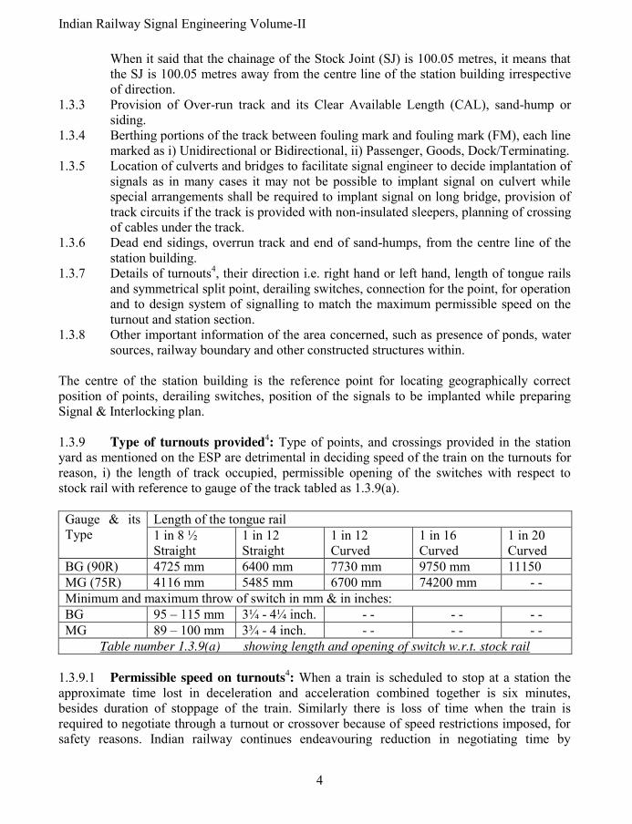
1.3.9 Type of turnouts provided4: Type of points, and crossings provided in the station
yard as mentioned on the ESP are detrimental in deciding speed of the train on the turnouts for reason, i) the length of track occupied, permissible opening of the switches with respect to stock rail with reference to gauge of the track tabled as 1.3.9(a).
Gauge & its Type
Length of the tongue rail
1 in 8 ½ Straight
1 in 12 Straight
1 in 12 Curved
1 in 16 Curved
1 in 20 Curved
BG (90R) 4725 mm 6400 mm 7730 mm 9750 mm 11150
MG (75R) 4116 mm 5485 mm 6700 mm 74200 mm - -
Minimum and maximum throw of switch in mm & in inches:
BG 95 – 115 mm 3¼ - 4¼ inch. - - - - - -
MG 89 – 100 mm 3¾ - 4 inch. - - - - - -
Table number 1.3.9(a) showing length and opening of switch w.r.t. stock rail
1.3.9.1 Permissible speed on turnouts
4: When a train is scheduled to stop at a station the
approximate time lost in deceleration and acceleration combined together is six minutes, besides duration of stoppage of the train. Similarly there is loss of time when the train is required to negotiate through a turnout or crossover because of speed restrictions imposed, for safety reasons. Indian railway continues endeavouring reduction in negotiating time by

5 Pramod P. Goel
modifying design of these turnouts. Permitted negotiable speed over different turnouts is tabled as 1.3.9(b).
Gauge Type of turnout
Switch angle Permissible speed in kmph
BG 1 in 8 ½ 10 34ʹ 27ʹʹ 10 for straight switch (speed reduced from earlier 15 )
BG 1 in 8 ½ 10 47ʹ 27ʹʹ 15 for curved switch (of 52/60 KG rails on PSC sleepers)
BG 1 in 8 ½ Symmetrical split (S.S.)
30 for curved switch as well as for S.S. with 52/60 kg on PSC sleepers.
BG I in 12 10 8ʹ -0 15 for straight switch.
BG I in 12 10 27ʹ 35ʹʹ 30 for curved switch for 52/60kg on PSC sleepers (permitted if all turnouts on which running train may pass throughout the section and the loco is provided with speedometer.)
BG 1 in 16 00 24ʹ 35ʹʹ 50 or 60+ (60+kmph permitted only for high speed turnout to drawing No. RDST/T-403.
MG 1 in 8 ½ 10 35ʹ 30ʹʹ 10 for straight switch.
MG 1 in 8 ½ 00 29ʹ14ʹʹ 10 for curved switch.
MG 1 in 12 10 09ʹ 38ʹʹ 15 for straight switch.
MG 1 in 12 00 24ʹ 27ʹʹ 15 for partly curved switch.
MG 1 in 16 00 24ʹ 27ʹʹ 30.
Table number 1.3.9(b) Existing speed restrictions on different turnouts.
1.4 Classification of the station
1: The stations are classified as, Class `A’, Class ‘B’,
Class ‘C’ or Class ‘D’ depending upon operational requirements. Conditions for granting line clear decide placement of signals based upon classification of the station [Indian Government Railways General Rules 2007] [For details refer to Indian Railway Signal Engineering- Volume –I, by the author same as that of this book].
1.4.1 Conditions for granting Line clear at a class `A’ station1: At `A’ class station, the
Line Clear may not be given for a train unless the line on which it is intended to receive the train, is clear for at least 400 metres beyond the Home Signal, or up to the Starter signal besides ensuring that: 1.4.1.1 The whole of the last preceding train has arrived complete; 1.4.1.2 All signals have been put back to `On’ behind the said train; 1.4.1.3 All points have been correctly set and all facing points have been locked for the
admission of the train on the said line.
1.4.2 Conditions for granting Line Clear at a class `B’ station on double line1: At a class ‘B’ station Line clear may be granted for a train before the line has been cleared for the reception of the train within the station section besides ensuring that: 1.4.2.1 The whole of the last preceding train has arrived complete; 1.4.2.2 All signals have been put back to `On’ behind the said train.

Indian Railway Signal Engineering Volume-II
6
1.4.3 Conditions for granting Line Clear at a class `C’ station1: Block Huts, where Line
Clear may not be given for a train, unless the whole of the last preceding train has passed complete at least 400 metres beyond the Home Signal, and is continuing its journey. This will include the Intermediate Block Post. 1.4.4 Non-Block stations or Class ‘D’ stations are stopping places between two consecutive block stations, and do not form the boundary of any block section. 1.5 Train traffic density, block section and direction of traffic: A section overloaded with traffic shall cause serious rail traffic jams, necessitating, i) conversion of absolute block section to Automatic Block section thereby enabling more trains to be pushed in the block section as against only one train with Absolute Block system of train working, ii) Using both lines, on a double line section, as twin single lines and as a last resort, iii) providing lines in addition to the existing, in the block section.
1.5.1 Train traffic density: The capacity to run the trains in a given section is worked out by charting possible running of trains, theoretically, including margin for maintenance of track, electric traction and signalling system. This, when compared to the actual trains running in the same section gives status of section over or under-loading. This in-turn shall dictate speed of the trains to be, and provide i) traction and traction equipment, ii) track geometry, iii) coaches and iv) signalling system, to be maintained or upgraded. If it is required to accommodate trains more than what are running so far, either more track or tracks is/are added in the block section or the existing track in the block section is provided with Automatic Block Signalling system to accommodate more trains in the same section. This may further require increasing holding capacity of road side or major terminal stations to avoid holdup in the train flow defeating the very purpose of adding additional line in the block section or providing Automatic Block signalling in the block section.
1.5.2 Block section and direction of traffic: Block section may be with single line, double lines, or more, connecting two stations, depending upon traffic requirements. Under the Absolute Block system with single line, only one train can be between two stations. More trains, running in the same direction, may be made to run if the section is provided with Automatic Block Signalling. Keeping the opposite direction trains waiting. IBS Signal cannot be provided on the block section with single line. Two trains can run simultaneously in block section with double line each defined as Up or Down line. This not only saves more than half of running time but also saves much time which otherwise would have been lost due to the train/trains waiting for the want of passage, phenomena called as ‘crossing of the trains’. In case when the train traffic is unevenly directional, both the lines on the double line block section are made bidirectional, used as twin single lines.

7 Pramod P. Goel
As discussed in preceding paragraph, the capacity of the section may also be increased by introducing Automatic Block Signalling on single, double or twin single line sections.
When the capacity of the section is saturated, more number of lines beyond two lines may be introduced in the block section. The Work is taken up by Dedicated Freight Corridor Corporation (DFCC), the PSU of Indian Railways. Lines are being added section by section in Ludhiana, Saharanpur, Khurja, Dadri, Kanpur, Allahabad, Mughalsarai, Sonnagar, Asansol Howrah Eastern corridor and, Dadri, Delhi, Rewari, Jaipur, Ajmer, Ahmedabad & Mumbai in Western corridor. Both projects are in advanced stages of progress. 1.5.3 Station Section
1: Within station section any number of lines may be introduced
limited by availability of land space with single or double main lines running across the station yard, depending upon the section or the station being situated on a junction point of more than two routes joining. However, all or as many lines may be designated as Up, Down or Bidirectional depending upon the yard’s requirements necessitating corresponding provision of crossovers and turnouts. It is pertinent to note that unless the capacity of the yard of the stations placed at certain intervals is commensurate to hold trains and also to pass running through trains, additional provision of lines in the Block Section may become in-fructuous as such station itself shall become bottle neck.
1.6 Signalling system at station yard or block section: Under the situations discussed in preceding paragraphs, any one of the signalling system, as listed below, may be adopted with the restriction that the system of signalling shall be same/identical with reference to adjoining block stations to which the Loco Pilot as well as for the maintenance staff of Signal & Telecommunication department of railways shall be able to adapt: 1.6.1 Within station Section
1,3,4:
i) Semaphore system of signalling, Modified Lower Quadrant, Two Aspect or Multiple Aspect, operated by levers.
ii) Two or Multiple aspect Colour light Signalling operated by levers or Central Control cum Indication Panel.
iii) Multiple aspect Colour light signalling operated by Computer based Visual Display Unit.
iv) Provision of Semiautomatic signals at the end of the station adjoining to which Automatic Block signalling is provided.
1.6.2 Within Block section
1,3,4:
i) Absolute Block system of train working. ii) Absolute Block system of train working with proving of block section clearance by
Axle counters, when Control cum Indication Panel is placed centrally. iii) Absolute Block system of train working with contiguously track circuited block
section. iv) Intermediate Block Signalling. v) Automatic Block Signalling on double line section.

Indian Railway Signal Engineering Volume-II
8
vi) Automatic Block Signalling on single line section. vii) Automatic Block Signalling on twin single line section.
*****
9 Pramod P. Goel
CHAPTER-II
PLANNING OF SIGNALLING SYSTEM
2.0 Signalling System1,4
: In a situation where a new station is being introduced in continuity of an existing section, all factors of the existing section shall be followed to maintain uniformity of signalling, for the Loco Pilot, such as if in adjoining station sections is provided with Semaphore two aspect signalling, the same system of Signalling shall be installed at the station in question, while the operating system may differ. However in case the signalling system different then the one scheduled to be provided on the destined station is required, it shall be at one end of the larger section, or the section concerned is required to be upgraded, this shall also start from one end or from both the ends of the larger existing section. On new line or existing system under major modification, the system of signalling shall be decided based on features of the section in consideration; A) Economic, B) Political, C) Security of Country, D) Goods. These considerations cumulatively shall in turn decide: i) Speed of trains specified for the given section ii) Standard of Interlocking to be provided, iii) type of signalling to be provided, iv) operating devices & media of transmission (Location for controlling the signalling system), v) operated equipment (signals & Points), vi) Type of Interlocking, vii) Monitoring devices to be used (Type of track circuits to be used in the station yard and in the block section), viii) Communication to be provided (between Section Controller, SM to Cabin Master , SM /Cabin Master and the level crossing gates within station section, within station limits and in the block section), ix) Power supply requirements for signalling system & communication and the x) Block working to be used. While introducing new scheme it shall be from one end of the section with suitable intimation to the Section Controller/Loco Pilot about beginning/modification of the new type of signalling system. 2.1 Features of the section in which the signalling is to be planned: Factors to decide features shall be i) Commercial ii) political and iii) Technical. (A) Commercial and political factors: Some routes acquire high mileage on account of commercial requirements such as leading of coal from coal mines to the thermal power plants, steel oars etcetera and gain political mileage on account of development of selected area. 2.2 The sanctioned speed: The sanctioned speed of the section decides standard of interlocking. The speed is sanctioned based on commercial, political importance, cost and technical considerations of the section. 2.2.1 Commercial and political importance of the section: Commercial and political reasons create traffic importance of the section and are broadly instrumental in deciding the

Indian Railway Signal Engineering Volume-II
10
signalling system. Certain area may be hand picked to uplift the selected zone politically or certain area may be selected due to its commercial importance because of coal or other mines or certain area industrially developed. It could become the route to run important passenger carrying trains such as Rajdhani Express or, other important main lines or branch lines to carry freight. On important sections where the time table is tightly scheduled, the operational time is required to be kept least. The Inter-cabin slotting is required to be eliminated by providing central panel to save operational time, on single line section token-less Block Instruments, are to be used instead of Token Block Instruments, Colour light signalling system and electrical operation of points with block proving of adjoining Block Sections shall be resorted to. (B) Technical factors: 2.3 Section capacity: If the section is over crowded using train traffic more than the capacity of the section, Intermediate Block Signalling (IBS) may be provided as first step. However Automatic Block Signalling shall be instrumental in enhancing the section capacity more than as compared to IBS. For ultimate enhancement of the Section Capacity Moving Block is the best solution; however Moving Block is not in use on Indian railways so far. 2.3.1 Single or double line sections: The signalling scheme and rules for single line section and double line sections are different as: 2.3.1.1 Overlap considerations: Keeping in view essentials of interlocking clause (i) of SEM 1988; 7.82, which reads as “It shall not be possible to take “Off” a running signal, unless all points including isolation are correctly set, all facing points are locked and all interlocked level crossings closed and locked against public road for the line on which the train will travel, including the overlap.” When the train is approaching and the overlap required to be kept clear beyond the first reception signal, before granting line clear, is termed as Block Overlap. When the train is running within station section, the Signal Overlap shall be provided beyond the signal up to which the train leads when the signal in rear is taken Off. i) Block overlap: For the trains entering into Station Section from the Block Section, in two aspect signalling area, the distance beyond the first stop signal, which shall be kept clear, shall be not less than 400 metres while the same shall be 180 metres if multiple aspect
signalling is provided. ii) Signal overlap: The track, to be set and kept clear, beyond the next signal, up to which the train is scheduled to lead from the signal being taken Off, is termed as Signal
Overlap. This distance is kept clear to ensure that in case the train overshooting the signal, it should not find an occupied track or open points, causing wrong movement, collision or derailment. This overlap shall be 180 metres in two aspect signalling area and 120 metres in case of multi aspect signalling territory, beyond the trailing point on single line section and beyond the signal up to which the preceding signal leads.

11 Pramod P. Goel
The overlap so provided shall be set towards running lines, Short Siding or the Sand Hump [Figure 2.3.1.1]: i) Short Siding of 180 or 120 metre metres length in case of two aspect or multi aspect
territory, respectively; ii) Sand Hump; As an alternative of short siding a Sand Hump of approved design with
at least one rail of 13 metres between point and the sand hump; or iii) Long Siding provided for shunting or stabling of hot axle or other damaged wagons
or coaches, with a trap point placed at a distance of 180 meters in case of two aspect signalling area or 120 metres in case of multi aspect signalling area, subject to that the portion of the siding between the signals, beyond which the overlap is required, and the trap point, shall be kept always clear.
iv) In case when no provision out of above three is available for the overlap to be set, it shall be towards the running line. If two or more routes are there for departure of the train, the points shall be set for overlap towards the route on which the train is proposed to be despatched, to avoid wastage of time at the time of departure.
In all the possibilities of setting of overlap as given as above, if the train is scheduled to depart for a specified route, immediately after stopping, the points shall be set for overlap accordingly, irrespective of all the provisions being available. 2.3.1.2 Granting of Line clear: Under Absolute Block system of train working, on single or double line sections the line clear shall be granted by the station, supposed to receive the train, only after complete arrival of previous train, Signals put back to ‘On’ and also when the track is clear up to an adequate distance beyond the first stop signal of the receiving station. However under Automatic Block system of train working, setting of direction of the traffic is essential, prior to granting of line clear on single line section, while direction is predefined on double line section. 2.3.1.3 Intermediate Block Signalling
1:
Many sections which are long enough to keep the train waiting for the want of clearance of the block section may be avoided by splitting the entire block section by providing an Intermediate Block Stop Signal (IBS). Block signalling system may be provided on double line section only. However any of the two or both tracks may be provided with the Intermediate Block Signalling. Many more variations are there in single and double line sections1.
siding with trap at 120mts.Overlap set for Long
TRAIN
STARTER
HOMEDISTANT
ROUTE
STARTERADVANCED STARTER
set for
ADVANCED STARTER STARTER
ROUTE
DISTANT HOME
STARTER
Overlap
TRAIN
Sand hump
Short siding
TRAIN
Overlap set for
STARTER
HOMEDISTANT
120mts.
ROUTE
STARTERADVANCED STARTER
Figure 2.3.1.1 Setting of overlap

Indian Railway Signal Engineering Volume-II
12
2.4 Gradients in and around the station section1: For designing the signalling system
for a given yard, gradient is one of the important factor as catch or slip siding shall be required to be provided for steeper gradients on either side of the station yard. Adequate protection shall have to be provided in the station section when the gradient is steeper within station section. 2.4.1 Under Schedule of Minimum Dimensions, a gradient steeper than 1 in 400 within
station limits is not permitted unless special safety devices are used and/or special rules are enforced. This dimension under recommended Schedule of Dimensions is 1 in 1200. 2.4.2 No station yard shall be constructed nor should any siding join a passenger line on a gradient steeper than 1 in 260, except where it is unavoidable and then only with the prior sanction of the Railway Board through Commissioner of Railway Safety, when a slip siding or other arrangement is made sufficient, to prevent accidents. 2.4.3 There shall be no change in grades within 30 metres of any points or crossings except in hump or gravity yards. 2.4.4 Beyond 45 metres of the outermost points at the station, with grades steeper then 1 in 400 metres, trains should not be drawn up to the last stop signal and held up on steep gradient, in order to clear the reception line for giving permission to the following train. 2.4.5 No shunting beyond outermost points on the steep gradient side should be allowed unless a locomotive is attached at the lower end of the lead from the point of view of gradients 2.4.6 On hilly area where railway track is having steep gradients, the failure of brake of the train or detachment of a vehicle from the running train can lead to rolling of the train or detached vehicle to the adjoining station placed on lower level and hit a train /vehicle standing there. To safeguard against such a situation, at a station where there is a gradient of 1 in 80 falling towards the station or 1 in 100 falling away from the station within 45 metres beyond the outermost points at either end, a catch siding in case of 1 in 80 falling towards the station and a slip siding in case of 1 in 100 away from the station should be provided. 2.5 Hot axle siding: A hot axle wagon can not be carried for long distance without getting derailed. Some times coaches, otherwise damaged, are also required to be stabled at roadside stations. The sidings are provided almost on all stations on busy route on each side of the direction of traffic as well as on up & down lines both. The sidings are placed at the station connected with main or loop lines in such a manner that minimum shunting effort is required to detach and place the coach or wagon. (Refer paragraph 5.8 Chapter IV of Volume-I of Indian Railway Signal Engineering, by the author same as that of this book). 2.6 Essentials of Interlocking
1,3: Essentials of Interlocking as provided in Signal
Engineering Manual form the basis of interlocking to be provided. In case of mechanical interlocking, the Interlocking Table is required to be prepared, in case of electrical interlocking Selection Table is required and in case of Electronic Interlocking, Rout Control Table is prepared, based on which the Locking Table (Dog Chart), Wiring Diagram and Interface

13 Pramod P. Goel
Circuits are designed. Any planning of signalling system can only be done with adequate knowledge of the essentials of interlocking.
2.7 Standards of Interlocking1: The ruling speed of the section, based on commercial &
political importance and technical obligations, shall decide the type and standard of interlocking to which the station is to be equipped. 2.7.1 Type of Interlocking and signalling system: Railway Board has decided that all future installations shall be provided as follows [Railway Board’s circular number 2003/Sig/G/5 dated: 14th September’2006]:
SN Number of routes Type of Interlocking to be provided
1 Up to 50 routes Relay based interlocking using metal to metal or metal to carbon relay contacts, according to expertise available on the railway.
2 Up to 200 routes Electronic Interlocking.
3 Above 200 routes Route Relay Interlocking (RRI) using metal to metal or metal to carbon relay contacts according to the expertise available.
Owing to pressing requirement and having gained experience for taking up of EI for more than 200 routes is under consideration of Railway Board. However in recent past Juhi yard with around 550 routes on Kanpur-Tundla section has been commissioned with multiple units of EI clubbed together.
2.7.2 Standards of Interlocking1: Standards of interlocking provide brackets of speed at
the station section with associated conditions and compliments of points and signals to be equipped.
2.7.2.1 Standard – I Interlocking: Maximum speed up to 50 Kmph through the station is allowed without isolating the track with the condition that i) all shunting shall be stopped and ii) no vehicles unattached to an engine or not properly secured by the Station Master, are kept standing on a connected line which is not isolated from the through line;
2.7.2.2 Standard – II Interlocking: Allows maximum speed of 110 Kmph with the condition that run through lines are isolated from all adjoining lines, the means of isolation are interlocked with the signal in such a way that the condition is maintained during the passage of the train, all goods lines are isolated from passenger lines; Double Distant signal is provided where braking distance of Goods trains is 1 Km or more;
2.7.2.3 Standard – III Interlocking: Allows maximum speed of 140 Kmph with all of the requirements of standard- II interlocking added with the condition that main lines shall be track circuited with the provision of mechanical interlocking and all running lines shall be track circuited with Central Panel Interlocking; Station provided with central panel on high density routes, shall have provision of means to verify complete arrival of train.
2.7.2.4 Standard – IV Interlocking: Allows maximum speed up to 160 Kmph with all the conditions of standard –III interlocking, with the addition that only central panel interlocking be provided with all running lines being track circuited, clamp lock type electric point machines on facing points on which such speed is permitted.

Indian Railway Signal Engineering Volume-II
14
It is pertinent to note that with the ruling speed of the section increasing from 50 Kmph to 160
Kmph, the signalling system varies upwards from semaphore signals to colour light signals,
point operation and its locking from rod or double wire point machine to electric point
machine with clamp lock, Interlocking and route holding from mechanical locking through
electrical to Electronic, Operation and control of the system by Levers to Computer aided
Visual Display Unit (VDU) through Control cum Indication panel, monitoring devises from
Lock Bars to Track circuits.
2.8 Type of signalling to be provided at the station section: Replacement of existing installation of semaphore signalling and all new installations is proposed to be done with Colour Light Signalling only. However in case of adverse circumstances such as non availability of stable and reliable power supply in the area in question, Semaphore signalling system may be proposed with the approved special instructions. All future new installations shall be provided with colour light signals. The signalling system on the station interlocked to Standard-I where the maximum speed permitted is 50 Kmph may be continued with rod operated points and two aspect colour light signals operated by levers interlocked mechanically. On existing single wire or double wire signalling installations semaphore signals’ replacement to On is done by using reverser, or signals placed distantly, operated by electric signal machines, are replaced to On by disconnection of power supply controlled by the interlocking circuit. The signalling system on the station interlocked to Standard-II where the maximum speed permitted is 100 Kmph may also be continued with rod operated points and multi-aspect colour light signals operated by levers interlocked mechanically with mainlines provided with track circuits. In this case, system may be controlled by Central Control cum Indication Panel provided that entire station yard controlled by the Control cum Indication Panel is track circuited. The signalling system on the station interlocked to Standard-III where the maximum speed permitted is 140Kmph, electrical or electronic interlocking shall be provided with the system operated by centrally placed Control cum Indication Panel; in this case the entire station yard controlled by the panel shall be track circuited. Complete arrival of the stopping train has to be verified by the Guard of the concerned train, causing loss of time necessitating verification of the block clearance through Single Section Digital Axle Counter. As such it is essential to provide block clearance device associated with Central Control Cum Indication Panel. In Moradabad - Bareili section of Northern Railway, the lever frames are retained to operate Multiple Aspect Colour Light Signals, illuminated using Cables and retaining point operation by rod at stations interlocked to Standard-III, in end cabins with mechanical levers and interlocking, while introducing 25KV AC traction. This being hybrid system for economic considerations, may be as a stopgap arrangement only.

15 Pramod P. Goel
However owing to scarcity of lever frames in the market due to scarce manufacturing and existing lever frame having been used for at least half of its life and also looking at oncoming operating devices being Control cum Indication Panel and electrical and electronic interlocking, it is considered more appropriate on economical and ease of availability considerations, to go in for Electrical or Electronic interlocking, controlled by Central panel or VDU and a Mouse, with electrically operated points on all new or major modifications to existing installations for station interlocked to standard-II and upwards. Signal control, in case of station interlocked to Standard IV, the provisions shall be as given under preceding paragraph number 2.7.2.4. 2.9 Systems of signalling: The system of signalling shall be known based on type of interlocking, be it mechanical, electrical, or electronic. However the signals and their operation may be either mechanical or electrical. Another sub classification is that mechanical system of signalling shall be single wire or double wire with mechanical interlocking; while electrical system of Interlocking shall be with Colour Light Signals operated by i) Mechanical levers and mechanical interlocking and, ii) Control cum indication panel. However Computer based Electronic Interlocking shall be operated by Visual Display Unit (VDU) and mouse, the signals being Multiple Aspect Colour Light. It is pertinent to note that in case of operating devices being Lever, the Mechanical
Interlocking Arrangements housed in the interlocking trough, the interlocking works as checks
and controls without interfering with the operation of the signalling system, bypassing the
system of operation, checks and feed backs, be it semaphore or colour light signals. However in
case of relay based Electrical Interlocking Circuits or the Electronic Interlocking, the Controls,
Interlocking and the Feed Back from the field, are processed through the Electrical Selection
Circuits/Central Processing Unit (CPU), the interlocking falling in between operating devices
and operated equipment. The power supply plays an independent role in managing the
signalling system.
2.9.1 Single wire system of signalling
1,3: Under single wire system of signalling, levers
are the operating devices, the media of transmission shall be single galvanised wire for operation of signals. The wire shall run in between lever tail through inside lead-out, outside lead-out, running on the pulleys hung on pulley stakes and horizontal rope wheels on diversion of the route, connected to the signal concerned, with detectors in between. The rod shall run from the lever tail through Inside Lead-out, Outside Lead-out, running on Standard roller guides, mounted on the trestles, with rod compensators in between, finally connected to the Adjustable Crank be it for point operation, facing point lock with or without lock bar, holding bar etcetera.
Two aspect semaphore signalling system, Levers shall be used to operate signals through single wire and points through rod, grouped in a lever frame placed under the control of Station Master, Under standard-I interlocking. On the section with light traffic, Outer signal may be operated from a location near facing point ensuring that the outer signal shall not be possible to be taken Off unless Home signal has been taken Off. Under exceptional circumstances Warner signal may also be operated from the same location as that of corresponding Home signal.
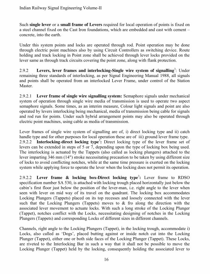
Indian Railway Signal Engineering Volume-II
16
Such single lever or a small frame of Levers required for local operation of points is fixed on a steel channel fixed on the Cast Iron foundations, which are embedded and cast with cement –concrete, into the earth. Under this system points and locks are operated through rod. Point operation may be done through electric point machines also by using Circuit Controllers as switching device. Route holding and track locking in Point zone shall be achieved through lever locks provided on the lever same as through track circuits covering the point zone, along with flank protection. 2.9.2 Levers, lever frames and interlocking-Single wire system of signalling
3: Under remaining three standards of interlocking, as per Signal Engineering Manual 1988, all signals and points shall be operated from an interlocked Lever Frame, under control of the Station Master. 2.9.2.1 Lever frame of single wire signalling system: Semaphore signals under mechanical system of operation through single wire media of transmission is used to operate two aspect semaphore signals. Some times, as an interim measure, Colour light signals and point are also operated by levers interlocking being mechanical, media of transmission being cable for signals and rod run for points. Under such hybrid arrangement points may also be operated through electric point machines, using cable as media of transmission. Lever frames of single wire system of signalling are of, i) direct locking type and ii) catch handle type and for other purposes for local operation these are of iii) ground lever frame type. 2.9.2.2 Interlocking-direct locking type
3: Direct locking type of the lever frame set of
levers can be extended in steps of 5 or 7, depending upon the type of locking box being used. The interlocking is actuated by the Tappets (also called as locking plungers) attached to the lever imparting 346 mm (14") stroke necessitating precaution to be taken by using different size of locks to avoid conflicting notches, while at the same time pressure is exerted on the locking system while applying force to operate the lever when the locking does not permit its operation. 2.9.2.2 Lever frame & locking box-Direct locking type
3: Lever frame to RDSO
specification number SA 530, is attached with locking trough placed horizontally just below the cabin’s first floor just below the position of the lever-man, i.e. right angle to the lever when seen with lever on mid way of its travel on the quadrant. The locking box accommodates Locking Plungers (Tappets) placed on its top recesses and loosely connected with the lever such that the Locking Plungers (Tappets) moves to & fro along the direction with the associated lever movement to actuate locks. With such a long stroke of the Locking Plunger (Tappet), notches conflict with the Locks, necessitating designing of notches in the Locking Plungers (Tappets) and corresponding Locks of different sizes in different channels. Channels, right angle to the Locking Plungers (Tappet), in the locking trough, accommodate i) Locks, also called as ‘Dogs’, placed butting against or inside notch cut into the Locking Plunger (Tappet), either one or both side faces of the Locking Plunger (Tappet). These Locks, are riveted to the Interlocking Bar in such a way that it shall not be possible to move the Locking Plunger (Tappet) held by the locking, consequently holding the associated lever to

17 Pramod P. Goel
which the Locking Plunger (Tappet) is attached, in its last operated position, when the lever is supposed to be locked in that position. In direct locking type of lever frame, lever pitch being 125 mm (5"), with locking trough designed for 5 as well as for 7 levers, up to 55/56 levers (multiples of 5 or 7) are provided in one cabin. The locking boxes are available for one channel or four channels. The pitch of the channels is 110 mm (4-3/8"). Each channel of direct type lever frame can accommodate three interlocking bars on to the top of Locking Plungers (Tappets) and three at the bottom, the Locking Plungers (Tappets) being sandwiched between the Interlocking Bars, consequently the friction becomes so much so that it is not practically possible to actuate the movement of Locks and consequently the locking when the interlocking bars are long enough. Besides larger size locking trough shall be required to accommodate increased quantity of interlocking material. This makes the Direct type of Interlocking Frame to become unwieldy for the levers more than 55/56. To overcome this situation catch Handle type/1924 type under RDSO specification number SA 1101, of interlocking frame is used. As and when levers more than 55/56 are required, per requirement of the yard, catch handle type of lever frame is provided. 2.9.2.3 Catch Handle type/1924 type of lever frame
3 to RDSO specification number
SA1101: Major variation with direct type of interlocking is actuation of interlocking on press of catch handle of the lever. The catch handle can be pressed only when the locking permits, as such the catch block which is attached with the catch handle shall not be lifted rendering the lever inoperative. This does not impose any pressure on the locking trough. The stroke of the locking plunger is also reduced imparting 2.56" such that the complication of conflicting notches is largely eliminated. In fact in this case the notches may conflict critically which can be overcome by accurate cutting of notches in the Locking Plunger. Up to 104/110 (multiples of 6/8/ or 10) Levers can be accommodated in Catch Handle type of lever frame, lever pitch being 100 mm (4"), and the locking box being for 6 channels for 8 as well as for 10 levers, 8 channels for 8 levers as well as for 10 levers and 10 channels for 8 levers as well as for 10 levers, due to locking box being smaller in size with reduced stroke of the plunger compared to direct type of interlocking frame. Each channel can accommodate two bottom and two top interlocking bars. 2.9.2.4 Lever-Lock
1 & its usage: Lever Lock is an electro mechanical device attached to
the lever-tail directly or through the down rod, used to control the movement of the lever. When point is operated by electric point machine controlled by lever, it is not allowed to be set to reverse position when the point is operated to set in reverse position from normal being check locked till the point is set and locked and Reverse Point Checking relay (RWKR) is energised and vive-versa. In another situation when there is no space to provide a lock bar to track-lock the point, under mechanical system of signalling, the Lever Lock shall be attached to the down rod (meant to be connected to the holding bar/lock bar but not connected there being no adequate space to accommodate the same), which shall be kept locked while the associated track circuit is
Indian Railway Signal Engineering Volume-II
18
occupied by the train/track circuit failure, thereby holding the point locked, and release the lever to be put back to normal only when the track circuit covering the point, is clear. This arrangement is also used for holding the route by cascading the lock levers keeping them back locked in the locking trough. 2.9.2.5 Transmission-Single wire
3: Signals are operated through 6, 8 or 10 SWG (Standard
Wire Gauge) galvanised steel wire, running on pulleys which are fastened to the pulley stakes. The gauge of the wire shall be chosen depending upon the tensile load
2. As and where the wire run is required to take a turn, a multi-stranded wire rope is inserted in between the GI wire run, to move on the Rope Wheel, which is fixed on a cast iron foundation embedded and cast with cement, concrete aggregate into the ground, for the diversion being horizontal or vertical. The wire rope and GI wire are joined using thimbles to avoid damage to the joint due to friction. The wire connected to the lever tail inside cabin is received on vertical wheel fixed just below the lever tail connection, taken out of cabin through horizontal wheel running on pulley stakes and finally connected to the counterweight lever upwards through vertical wheel fixed on the signal post. The counter weight work to pull the wire back when the lever is replaced to on. 2.9.2.6 Transmission-rod run
3: Class-I steel solid rod of 33 mm (1¼") diameter, weighing
not less than 4 pounds/feet, is used to operate points running and resting on to the standard roller guides between bottom roller and top roller to ensure that the rod does not buckle up/down or either side. The Standard Roller Guide is firmly bolted on to the Trestle, which are embedded into the earth compacted firmly to ensure no movement to the trestle. One end of the rod is connected to the lever tail and other on to one arm of the vertical crank which is placed just below the joining point of the lever tail, bolted with the channel provided to bear all such vertical cranks. The crank converts vertical movement of the rod to horizontal to take it out of the cabin connected to the other arm of the vertical crank and terminate on one arm of the accommodating crank which is fixed onto the lead-out foundation plate/girder to which all such accommodating cranks are bolted. Both the cranks have arms at right angles to each other, due to which the subsequent rod run shall run shall take diversion at right angles only i.e. right angles to the rod coming out of the cabin up to lead out and for each such turn. This way the rod shall run parallel to the track till it reaches near the point, to be terminated on the sleeve of the Adjustable Crank. The rod to be connected between the sleeve of the adjustable crank and the lug provided on the stretcher bar (provided along with laying of the points by the Engineers to maintain gauge fixed holding both the tongue rails bolted with the ends of the stretcher bar), having an adjusting screw in between both ends of the rod, to enable make balance between the tongue rails for a given strike by the Adjustable Crank, to be adjusted such that the tongue rails set against corresponding stock rail sets not only without any gap but also exerting some pressure against the corresponding stock rail, with the combination of adjusting screw and the sleeve. It may be appreciated that a gap of more than 5 mm measured by putting an obstruction piece at 150 mm (6") from the toe of the tongue rail, between tongue rail and the stock rail is considered unsafe.

19 Pramod P. Goel
Such a situation may arise if the expansion & contraction in the rod run with the ambient temperature variations is not compensated. As such it becomes imperative to provide rod compensators in between alignment at calculated intervals. These roding compensators have two cranks one with obtuse angle and other with acute angle connected through a link. The compensators are connected in the rod run by acute angle crank keeping on lever side. As the arm of one of the cranks is moved to either side the arm of the other crank moves equally to the opposite direction thereby the direction of the transmission is reversed at each such compensator. This reversal is to accommodate the expansion and compression of the rod. These roding compensators pose restriction due to radial movement of arms of the cranks, as with the right and left movement of the arm of the compensator’s crank which is connected with the rod on either end at right angle to alignment with the hub of the crank the alignment of the rod run shall be deflected out of alignment which shall be to the limited extent only to avoid bending of the rod, thereby limiting the length of the compensator crank’s arm connected to the rod. This compels provision of the compensators to be more than one depending upon the total run of the rod from start to the end. Accordingly the position for placement of these rod compensators has to be calculated by the designer. Rod compensators and all cranks are bolted to the cast iron foundation which is firmly embedded into the earth and cast with cement, concrete and gravel aggregate. While the length of transmission can be up to distance of 460 metres from the cabin for operation of point lock and bar, the double ended point can be operated up to maximum on running lines with 200 mm (8") stroke can be operated up to 275 metres (300 yards)3. No compensators are required for the length of the rod up to 12 metres for point operation and 18.5 metres for Lock & Lock bar operation when the stroke at the lever tail is 200 mm, range of temperature variation being 1500 F over the year. 2.9.3 Double wire system of signalling, operating devices and transmission
1,3:
Operating devises of double wire system of signalling are double wire Rope Drum Levers bolted on the girder forming the Lever Frame. In case of rod operation of point, the operating device shall be either i) double wire Rope Drum Lever when point is operated by double wire point Mechanism or ii) Rack And Pinion when operated through rod. 2.9.3.1 Double wire system of signalling
3 ; Levers & Lever frame: Under double wire
system of signalling, the levers used for operation of signals, points and other functions are i) Direct lever, ii) Clutch lever, iii) Rack & Pinion lever and iv) Miniature lever. Other levers such as, a) three to one lever and b) Auxiliary or Clutch Resetting Lever, are used for adjustments and resetting respectively. The Rope Drum of the Direct Lever is rigidly connected to the Lever Handle such that in case of wire breakage, the drum does not move (does not trip), thereby not disturbing the interlocking. Lever Handle is not rigidly connected with the Rope Drum in case of Clutch Lever due to which, in case of wire breakage, the drum shall rotate to either side depending upon breakage of the pull or push wire, the rotation being limited in case of tripping but enough to foul the interlocking. However, in case of trailing, connected to a trailable point machine, the movement of the rope drum shall be about 22 ½ inch. The lever shall be reset after setting right the broken wire, using Auxiliary Lever. Points, Facing Point Locks, Economical Points, Lock

Indian Railway Signal Engineering Volume-II
20
retaining bars or Holding- bars, Fouling-bars, Detectors and Signal transmission with Detectors are worked by Clutch Levers. The trailable lever is similar to clutch lever except that the rotation of the drum in case of trailable lever is free of the lever handle in broken wire conditions when the pair of points are trailed through. Rack and Pinion Lever is designed to be fixed along with double wire levers in the same lever frame to work the Points, Locks and Lock Bars through rod run using Rack and Pinion arrangement. Miniature lever is not for transmission of operated equipment but is used to receive or transmit a control while actuating interlocking. Three to one liver is used for testing the tension difference between two wires of the transmission required to trip a clutch driven lever while Auxiliary lever is used for resetting the tripped Rope Drum. 2.9.3.2 Operation of Signals-by double wire
3: Levers operating signals with rotary
detectors in series or rotary detectors by itself are likely to face obstruction due to improper setting of points and as such are allowed to trip/trail, making further movement not possible as drum is disengaged with the lever. The levers, under the system of double wire operation are fastened on a iron channel, bolted in place. A Signal Mechanism is fixed near the base of signal post, having a cam path, crank with roller at one end and other end connected to the driving rod/down rod in-turn connected to the signal spectacle and stoppers to limit the Signal Mechanism drum movement to desired position. As the lever is operated to rotate the lever drum, the Signal Mechanism drum also rotates correspondingly, which in turn makes the roller attached with one arm of the crank to move along the cam path and impart stroke to the down rod and consequently operate the signal arm to Off or On position as desired. 2.9.3.3 Operation of points by double wire
3: Under double wire system of signalling, the
operation of points shall be through either double wire point mechanism or through rod operated points. In case of double wire point mechanism being used, the Clutch lever shall be used while in case of rod operated points, rack & pinion type lever shall be used. Point detection in any case shall be through rotary wheel detectors. 2.9.3.4 Transmission and Double wire compensators
3: Under double wire system of
operation, a paired loop of the wire is used one end of which shall be wrapped around drum of the lever and other end is wrapped around the drum of point or signal mechanism. Evidently the loop has to be kept taut to ensure that the transmission imparted by rotating the lever drum through the lever has to be received at the signal or point mechanism or independent detector end, which in turn operates signal, the point or detector. Any loss of stroke due to sag in the wire shall result in inadequate rotation of the point or signal machine drum or detector which in turn shall result in inadequate operation of point or signal as the case may be. To ensure such loss of stroke at the operated end not to happen, double wire compensators are used which not only keep the wire loop taut but also accommodate ambient temperature variations.

21 Pramod P. Goel
2.9.3.5 Interlocking for double wire: Interlocking trough is attached with the lever frame at an angle appropriate to transfer the locking stroke to the locking plunger (Tappet) housed inside the locking trough. Accordingly the interlocking is checked at the stage of pressing of the Catch handle itself, before any movement of the Lever Rope drum takes place. The special feature of the interlocking arrangement is tight and loose locking. With the trailing/tripping of the Lever Drum the associated locking plunger (Tappet) shall move to the extent that it does not actuate the interlocking within interlocking frame due to locking notch being made long enough to accommodate the travel of the plunger in case of tripping/trailing. However as the conditions warrant when the locking is required to be actuated, the notch on the locking plunger (Tappet) is not elongated resulting in actuation of the locking with movement of the locking plunger (Tappet) due to tripping. This is tight locking. Under double wire system lower or upper quadrant semaphore signals and double wire point Mechanism shall be operated. The points are also operated by rack and pinion lever through rod run especially when the point operated by double wire point Mechanism is not detected by double wire point detector. Point may also be operated through electric point machine using Circuit Breakers similarly as in case of single wire system. When detection is required, double wire mechanical detectors shall be used where points are operated by double wire point Mechanism, however electric point detectors shall be used when points are rod operated. Electric detection is inherent with operation of point through electric point machine. 2.9.4 Hybrid arrangement of Mechanical interlocking supplemented by electrical
interlocking: There are compulsions to convert the mechanical system of signalling to colour light signals retaining the lever frame in the cabins to operate the same. As the semaphore signals are replaced by the colour light signals the operation of points and the interlocking is retained as it was. To replace the signals back to On and for monitoring track vacancy, the station section is track circuited except the point zones. The electrical interlocking is provided to control the signal aspect, its automatic replacement back to On, inter-cabin slotting and supplement the interlocking to the limited extent. 2.10 Power frame: Miniaturised lever frame, with its levers interlocked electrically, is used for electrically controlled signalling system. The lever frame consists of miniaturised levers, which move over the quadrants, and operate the circuit controllers attached with each lever actuated by electrical interlocking and to operate the signals and points. As the interlocking arrangement with tappets is totally eliminated, the levers are locked or released in conformity to the interlocking relations through miniaturised locks attached to each such lever. [Figure 2.10]. 2.11 Ground lever frame: Ground levers/lever frames are used at level crossing gate with locking trough, for boom locking and also for taking Off the gate signals or giving slot, under system of mechanical operation of gate, for operation of outer signals under standard-I interlocking as discussed in preceding paragraphs, for operation of signals and points locally.

Indian Railway Signal Engineering Volume-II
22
The lever with quadrant is fixed on channels, which is fixed onto cast iron foundations embedded into earth and cast with cement & concrete at each end of the channel. Locking trough and circuit controllers are attached to the quadrants.
2.12 System of Electrical Signalling
4: System of electrical signalling may be with
electrical interlocking or electronic interlocking. 2.12.1 System of Electrical Signalling with Electrical Intorlocking
4: Many of the features
of interlocking which may not be achievable through mechanical means can be obtained through electrically manipulated logic and switching circuits using switching device/Relay. These logic and switching circuits constitute electrical interlocking. Operation of signalling system shall be through push buttons in case of route setting type of system of operation or some times through a combination of push buttons and rotary switches, in non-route setting type system of operation or as discussed in preceding paragraph ‘Hybrid arrangement of Mechanical interlocking’, it may be through levers and associated Circuit
Figure 2.10 Electric Lever Power Frame
Everglades Junction signal box with its Westinghouse Brake & Signal Co. Ltd. Style 'L'

23 Pramod P. Goel
controllers which in turn are used either to control the signalling circuits directly or energise normal and reverse proving relays to correspond the position of the lever concerned, in-turn controlling the interlocking/logic circuits. 2.12.2 Operation by Control cum indication panel
1,3: With the advent of electrical
interlocking, operation of signalling system became very convenient, replacing levers by switches and push buttons, provided on Control Cum Indication Panel. The panel has replica of complete yard plan with signals, points, and level crossing gates depicted on its top surface along with associated indications of track circuits, signal aspects, point settings, crank handles locked or released, level crossing gates locked or free. Counters are provided to count emergent operation of points, signals, release or cancellation of routes and many more such features. In earlier versions of control cum indication panels with non route setting type of interlocking, the points are required to be set individually by operating rotary switches meant for the purpose, provided on the panel. After the points are set, the Signal and route buttons are pressed to take the signal Off for the route already set. However now after introduction of route setting type of Control Cum indication Panel, the route is set and signals taken Off by pressing of signal and route buttons. 2.12.2.1 Non-route setting type system of operation
4: Earlier system of electrical
interlocking operated by push buttons, on control cum indication panel, used to be designed with route setting by operating each point individually using rotary switches and then after the points were set and locked in desire positions, signal & route buttons has to be pressed to take the signal Off after checking for interlocking of conflicting routes, correct setting and locking of points, locking the route. The arrangement has been modified under which pressing of two buttons shall set the points and take the signal Off. 2.12.2.2 Route setting type system of operation
4: Under Route setting type system of
operation, pressing of signal and route buttons shall initiate checking the conflicting routes, and if found none of the conflicting routes in use, shall give command to all the points to be set to normal or reverse as per requirement of the route concerned, as and when the concerned points are set and locked for the desired route, the route shall be locked, route lights be displayed on the control cum indication panel, the signal be taken off and its aspect be displayed on the panel. 2.12.2.3 Arrangement of Push Buttons and associated indications is detailed as below: i) Push buttons
4: The buttons provided on the panel top are spring loaded, which return back to its normal position when released. A buzzer makes a sound along with illuminated visual indication if the button is kept pressed or remains pressed inadvertently or for any reason such as placement of a book or due to damaged spring, etcetera, for more than 10 seconds. Main push buttons are designated as `Signal button’ and `Route button’ on the panel. Signal button is provided near the foot of the signal and route button is provided on the track profile on which the train is to be brought. This arrangement is same for Shunt Signals also. Pressing of signal button and route button communicates the intention of the Station Master to the interlocking system for moving the train from the desired signal up to the next stop signal on the selected route. The system translates the command into desired action.

Indian Railway Signal Engineering Volume-II
24
As and when a point fails to operate or to set to desired position within prescribed time or a signal fails to take Off due any reason or fusing of lamp, a buzzer shall ring along with an illuminated indication. The buzzer can be silenced by pressing acknowledgement button while the indication shall continue to glow till the cause of failure is rectified. For the purpose of quick identification, all buttons on the panel are coloured distinctively [Table 2.12(i)].
SN Button type Colour & placement on the panel Code
A) Main buttons for operation of signals, points & release or locking of crank handles as mentioned at SN 1 to 11 below are with reference to clause 21.2.11 of SEM Part II, September, 2001and balance are as adopted by different railways:
1. Main running signal Red: in between route strip profile GN
2. Calling on signal Red with white dot: On top row of the panel
COGN
3. Shunt Signal on the same post as that of main signal
Yellow: by the side of route strip profile near the shunt signal profile.
SHGN
4. Shunt Signal Independent Yellow: in between route strip profile. SHGN
5. Individual point operation Black: placed near each point profile. WN
6. Exit (Route button) White: with route name printed by its side. UN
7. Alternative route Grey: with route name printed by its side. UN
8. Alternative overlap White with black dot on its top. OYN
9. Slot (Individual) Green. YN
10. Crank handle (Individual) Blue: placed near the point profile for release or withdrawal of control of crank handle operated with group button.
CHYN
11. Point group Black with red dot. WWN
12. Level Crossing (individual) Grey. XN
13. Release of control over ground Frame lever operated point
Green. YN
B) Following group and other purpose buttons are placed on the top row of the panel:
1. Calling-on group. Red COGGN
2. Overlap release group. Grey OYN
3. Emergency route release group. Grey EUUYN
4. Emergency sectional route release group. Grey EUYN
5. Emergency signal cancellation group. Red EGRN/ ERN
6. Emergency point operation group. Blue EWN
7. Common Group release button for Slot, Crank handle, and Level crossing gate.
Grey GBRN
8. Common Group lock button for Slot, Crank handle and Level Crossing gate.
Grey CBN
9. Switch for changeover between panel & computer. White - -
10. Acknowledgement buttons for, point failure, lamp fusing etcetera for silencing the buzzers.
White - -
Table 2.12(i) Push buttons and their distinctive colours
ii) Indications: Indications on the panels are, status of i) track circuits, ii) setting of points normal or reverse or failed, iii) route set, iv) route locked, v) point locked in any of the route, vi) level crossing gate controlled by the Station Master through panel, locked or free, vii)

25 Pramod P. Goel
crank handle locked or free, viii) health of power supply, ix) health of time element relay, x) health of flasher relay, xi) signal lamp fusing indication, xii) health of SSI system, xiii) signal passing at On indication when Intermediate Block signal is provided in adjoining block section, xiv) train entering block section indication, xv) train entering into station section indication and many more indications are also provided onto panel face.
SN Indication Description
1 Signal Signal aspects repeated on respective signal profile in a circle
2 Signal route indicator
A white inclined/vertical slit at the top of the signal profile when signal is taken Off with route.
3 Calling on A white inclined slit when Calling on signal is lit.
4 Shunt Signal Independent
When On- white horizontal strip, Off – a white inclined strip.
5 Shunt Signal dependent
When On- No light, Off – a white inclined strip.
6 Point Two route strips one straight and other inclined to the main alignment out of which one steadily illuminated strip straight to alignment indicates point set for straight and otherwise reverse respectively. Both the strips flash simultaneously, while point is moving from normal to reverse or reverse to normal or when permanently failed to set in either position, to flash for maximum 10 seconds.
7 Point locked in route
A white circular indication on the junction of two route strips show point locked when illuminated.
8 Route section A set of minimum two strips for entire length of each track circuit depict white light in the route section, only when route is set which shall turn red when the concerned track circuit is occupied or failed.
9 Route locked A circular white indication by the side of the signal which illuminates when emergent route release is initiated and continues glowing during only for the period the locked route is being released.
10 Crank handle Out of the two circular indications near the individual crank handle button, one white light illuminates when the concerned group of crank handle is locked and the other red light illuminates during the period the crank handle is kept released.
11 Flasher A circular flashing indication on panel top to show that the flasher is working properly.
12 Time element A common circular indication on panel illuminates to show release of any route in progress for 120 seconds. There may be more than one such indicators on one panel.
13 Power supply White circular indication for each system i.e. 12 V DC, 110 V AC & other important power supply’s health status.
14 Train passing IBS signal at On
A circular white indication illuminates to indicate train passing IBS signal at On.
15 System of SSI functional
A circular indication illuminates in case of SSI system fails.
16 Signal lamp failure
Red circular indication illuminates when any of the signal lamp in the group fuses.
17 Panel -VDU The switch with white circular illuminated indication to show operating device in use being Panel or VDU.
Table 2.12(ii) Indications on the panel

Indian Railway Signal Engineering Volume-II
26
Some of these visual indications needing immediate attention of the Station Master are associated with the audio alarm also. These alarm & on panel face help the Station Master in maintaining a close watch on the activities in the station yard and thereby operating and controlling train movement inside the station section and block section [Table 2.12(ii)]. iii) Counters: Some of the operations such as emergent release of route, route section, overlap or emergent operation of point, which are related with safe running of trains, are counted automatically with the release operation taking place, for the purpose of maintaining record of such a situation having arisen. Besides in case any unsafe incidence occurs while making such an operation the counter record shall be able to establish that it happened during such an operation. Actions counted are provided in table 2.12(iii):
SN Button with counter Action Counter abbreviation
1 EGNR Emergent signal replacement EGGZ
2 EUYN Emergency Section route release EUYZ
3 EUUYN Route release (complete) EUUYZ
4 COGGN Taking Off of Calling on signal. COZ
5 EWN Emergency release of point EWWZ
6 OYN Emergent release of overlap OYZ
7 IBS passed at On IBS passed at On, advise next station. - -
Table 2.12(iii) Indications on the panel
2.12.2.3 Route relay Interlocking (RRI): In earlier version of control cum indication panel, each point is required to be set individually by operating dedicated rotary switch meant to control each point or pressing common press button with the button of the point concerned, before pressing two buttons for taking the signals Off, while route setting type of signal control panel was working under the name of RRI. However over the period with the route setting type of system having been introduced for control cum indication panel also there is no difference between RRI and Control Cum Indication Panel. To differentiate between the two, RRI word is being used for larger yards. 2.12.3 System of Electrical signalling with electronic Interlocking
4: Electrical
interlocking with switching relays, although a leap improvement over mechanical system of signalling/interlocking is still a generation back as it requires large accommodation to be installed, generating huge heat some times necessitating air conditioning of the room where it is housed, large quantity of copper conductors and moving parts of electromagnetic switching relays, offering high resistance to its contacts susceptible to offer due to dust, or soldered terminals of wiring. Initial installation and modifications at the later stage need large time and manpower. Computer based Electronic Interlocking4 eliminates almost all of the deficiencies mentioned in preceding paragraph. Different vendors who offer Electronic Interlocking, by and large use one of the i) Free wire or ii) Generic system of software based interlocking4. With each out of these systems, indications on panel and the Station Working Rules (SWRs) shall bear the associated features of indications and operating procedure, respectively.

27 Pramod P. Goel
2.12.3.1 Control cum Indication Panel or VDU4: Under relay based electrical interlocking,
the multiple aspect colour light signalling system is controlled by the Control Cum Indication Panel. In case of Electronic Interlocking the signalling system is controlled by the Control Cum Indication Panel or VDU of the computer with a mouse or either of the two whichever available. When both the operating devises are used, a switch is provided on the control cum indication panel to transfer the control over VDU from the panel and vice-versa. The arrangement of dual operation was mooted as the Station Masters did not feel comfortable operating the VDU. However with the younger generation joining, control of signalling system is being done singularly through VDU & mouse. Operation through VDU is by using mouse. The portion of the yard is depicted on clicking the mouse and further action to take a signal Off or put it back to On is carried out4. The indication part of the Control cum Indication Panel bears a replica of the station yard on its face depicting running signals, Shunt Signals, Calling-on signals, points, track circuits and other indications to facilitate the Station Master in knowing the complete status of the yard. The operating panel could be Route setting type of non route setting type. 2.13 Route holding, approach and back locking, track locking, lock bar, fouling and
clearance bars4: In compliance to essentials of interlocking, the route once set and the signal
having been taken Off for the given route, it shall not be possible to alter/disturb the route till the train has reached its destination except under special circumstances with adequate measures to maintain safety to the train. The route beyond the signal is held in two situations viz. i) approach locking, when the train is approaching the signal and ii) back locking when the train has passed the signal. 2.13.1 Route holding, approach and back locking and track locking mechanically: Under mechanical system of signalling, the approach locking is left to the Cabin Master’s discretion as the route shall be held locked till the signal lever is not put back to normal. The back locking is achieved by providing holding bars spaced to the maximum of 180 metres between the signal concerned and the first point to be held locked and also between each other if the distance between the signal and the point is more tan 180 metres, followed by the same sequence up to the foot of the destined signal. In case the first point falls within 180 metres from the signal no holding bar in between shall be required to be provided. A holding bar as such is not attached to the lock and serves the purpose of holding the route only. A lock bar attached to the facing point lock with the radial guide provides track locking to ensure that the point can not be unlocked having been pressed under the wheels of the train. As and when a train is being received on main line, the last vehicle should not be allowed to be placed when the train has stopped, within the fouling mark, to avoid a side collision with other train. To ensure this not to happen, a fouling bar is provided attached to the trailing end of the point leading to loop line when reversed. It shall not be
Fouling Mark
{
Fouling bar
Clearance bar
Figure 2.13(i)
Fouling mark, Fouling & Clearance bars

Indian Railway Signal Engineering Volume-II
28
possible to reverse the said point with the clearance bar under the wheel of the last vehicle standing on the main line, thereby preventing reception of the next train on loop line till the Clearance Bar was clear of the wheels. Under similar situation when the train is being received on loop line a clearance bar is attached with the trailing end of the point on loop line in which case if the last vehicle of the train occupies the clearance bar keeping it pressed under the wheel thereby not permitting change in route. The arrangement is termed as Flank Protection. [Figure 2.13(i)]. 2.13.2 Route holding, approach and back locking and track locking Electrically: Under the system of electrical interlocking flank protection is achieved by providing track circuits placed in such manner that so far as the track circuit, meant for verifying track vacancy as well as for flank protection, is occupied by the train, the signal leading on to such track, shall not be possible to be taken Off [Figure 2.13(ii)]. Track locking under the system of colour light signalling, operated by levers, is achieved through lever lock which shall not release the facing point lock lever till the track circuit covering the point zone is occupied by the train. [Figure 2.13(ii)]. Under Electrical system of Interlocking the track locking is achieved through Track Circuits manipulated by relay based selection circuits. 2.14 Effect of traction used in the section for train haulage: Diesel engines, and locos driven by DC and AC tractions influence planning and designing of signalling system proposed to be used in many ways. 2.14.1 Diesel Engines (diesel traction): Diesel locomotive though is fuelled by the diesel oil to run the generator within it applies the electricity so generated to drive the loco. Accordingly to call this traction as diesel is misnomer. However to accommodate the diesel generator within the loco body on hood of the engine has to be larger. Type of the locomotive plays vital role in designing the signalling scheme and Clear Standing Room (CAL) on the berthing tracks and other track circuits such as track circuit for replacement of signal to On. 2.14.2 Electric traction
1,4: Electric traction as in-vogue in country is 1500 V DC, 3000V
DC and 25 Kilo Volt AC. 2.14.3 DC traction
1: With the 1500 V DC or 3000 V DC traction in use, the DC traction
return current shall return through rails, and shall interfere with DC track circuits. As such only AC track circuits with two position or three position relays, Jeumont track circuit with 83½ pulse rate, Audio frequency track circuits or Axle counters or Axle Counters can be used.
circuited area
Fouling Mark
Track
Figure 2.13(ii)
Fouling mark, Flank protection & Track
locking

29 Pramod P. Goel
2.14.4 25 KV AC traction1,4
: When 25 KV AC traction is used in the section, DC track circuits shall be used to avoid interference due to AC traction return current besides Jeomont track circuit with 83½ pulse, Audio frequency track circuits or Axle counters can also be used. Under mechanical system of signalling, to avoid any person using or working on the system and getting electric shock, all rod and wire run running out of cabin shall be insulated using rod and wire insulators respectively. All rod and wire run shall be insulted just before terminating on the stretcher bar and signal also. Winch operated lifting barriers wire shall be insulated just near the winch and just before lifting barriers in such a way that the person operating winch or the person repairing or working on the lifting barrier are not electrocuted due to any contact with rails or any other reason. All signals, apparatus cases and field appliances with least possibility of the same coming in contact with rails or subjected to linear parallelism shall also be earthed. All relays placed outside cabin shall be on double wire working on power supply isolated from other power supply used for internal circuits. All precautions shall be taken to eliminate effects of induced Electro Motive Force (e.m.f.) generated onto the Cable running between relay room and operated equipments such as signals and points. 2.14.5 Effect of traction and loco on Clear Available Length (CAL): It may be appreciated that while the Clear Standing Room (CSR) is depicted on the ESP, the CAL is depicted on the Signal & Interlocking Plan to enable the Station Master decide for reception and berthing of the train vis-à-vis the length of the train. 2.14.5.1 Accommodation for berthing of train: Difference between Clear Standing Room (CSR) i.e. length of track between fouling mark to fouling mark as given on the ESP and Clear Available Length (CAL), the length of the track for berthing of train, left available to accommodate the longest train, after leaving margins for the track circuit for fouling protection, lock bar, fouling bar and clearance bar and protection against Loco Pilot getting confused due to signal going back to On while Diesel engine with longer hood leading, is moving out of the berthing track. 2.14.5.2 Loco factor: In case of electric traction, the loco is symmetrically designed at both the ends as the electric motors are placed in between the Loco Pilot’s cabs. This requires the distance between the signal and the signal replacement track circuit placement to be 6 metres. In case of diesel driven traction, which has to accommodate a diesel generator to drive the loco one hood has to be longer than the other. The locomotive may move with long hood leading or small hood leading. In case of long hood leading the Loco Pilot, who is placed far behind the leading wheels of the loco, must not be able to see the signal being replaced to On due to signal replacement track circuit getting occupied by the leading wheels of the loco before the cabin of Loco Pilot passes the signal. To make this not to happen, placement of the track circuit at such a distance from the signal is necessitated. This distance is reckoned as 13 metres.

Indian Railway Signal Engineering Volume-II
30
If the operation of point ahead of the signal is mechanical and the lock bar is required to be placed for holding of point as well as the route, the distance between the signal and the signal replacement track circuit shall be about, but not less than 13 metres irrespective of the type of loco, but in case the point being operated by electric point machine the distance shall be governed by the type of loco running or likely to run in the section to ensure track-locking. On entry end of the berthing track also if the point is operated mechanically and a fouling bar/clearance bar is required to be provided on the trailing end of the point on the track in question, another 13 metres length shall have to be kept clear (length of the bar) at the entry end too. The distance available on to the berthing track is marked between fouling mark to fouling mark on the Engineering Scale plan (ESP). The Clear length on the berthing track on loop lines is also marked as CSR which gets reduced to CAL, due to the constraints of type of traction and type of operation of points as discussed above. Minimum CAL is specified to be 710 meters. 2.15 Safety features: The signalling system installed at a station shall essentially have, i) signal, operated by lever or Control cum indication panel. There may also be, ii) points, and iii) level crossing gates within the station section/station limits. As all the three operated equipment are interlocked with each other, there apparently shall be no situation which could create unsafe conditions unless the command given through the lever or the control cum indication panel is executed faithfully, failing this correspondence between operating device and operated
equipment, disastrous conditions may arise. The other important component of safety is monitoring the presence of the train or track vacancy of a given section of the track. 2.15.1 Correspondence between operating devises and the operated equipment
4: While
operating devices are lever, control cum indication panel and VDU with mouse, corresponding operated equipments are signal, point and level crossing gate. The correspondence between operating device and operated equipment is checked through methods used as given in ensuing paragraphs. 2.15.2 Correspondence between control and operation of point: When point is operated by lever through double wire using double wire point Mechanism, steel rods or electric point machine, it must be ensured that not only the point sets to the position corresponding to the lever when operated by lever, the desired operation carried out by pressing push buttons placed on the control cum indication panel or by giving command from VDU, for independent operation of point or due to command for taking the signal Off for a given route, but is also locked independently (apart from being locked with a route). For this, mechanical or electrical point detectors, as the case may be, are used to determine the correspondence. When point is operated by lever through rods, an independent electric point detector shall be used while when the point is operated by an electric point machine a separate or inbuilt electric point detector shall be used for correct and proper setting and locking of the point. 2.15.3 Correspondence between control and operation of signals: In case of semaphore signal, the correspondence of the signal arm during day and correspondence of the arm along
31 Pramod P. Goel
with illumination, by kerosene oil lamp during night, shall be checked through ‘Arm & light Repeater’ with reference to the operating lever. The correspondence between lever, or the command generated from control cum indication panel or the VDU, and corresponding aspect of the signal, in case of colour light signal illuminated by incandescent lamp, is proved by an Electric Lamp Checking Relay (ECR) placed in series with the limb supplying power to the lamp. The relay is current sensitive and is kept de-energised normally. It is energised only when prescribed minimum current flows across its coil when the signal lamp is illuminated. With the incandescent lamp getting replaced by light emitting diode (LED) signal, a ‘Health monitoring Device’ is also provided in the signal lighting circuit, along with the ECR to monitor performance of the cluster of LEDs. 2.15.4 Monitoring track vacancy, of a given section of the track
4: Monitoring of the track
can be done by providing the track circuit which may be any of, DC track circuit, AC track circuit, Audio Frequency track circuit or uneven waveform track circuit superimposed on rails of the track; Axle counter as another electronic device which is not superimposed on the rails of the concerned track but attached to the rail to count-in or count-out the axles of the passing train. Other special feature track circuits such as coded track circuit are also used for the purpose of transferring certain information to the loco pilot running the train with the contact between Loco wheel and the track.
Track circuit is the device to monitor presence of a vehicle or train on a defined portion of the
rail track. As per GR 1.02 (57) the track circuit is defined as “An electric circuit provided to detect the presence of a vehicle on a portion of track, the trails of the track forming part of circuit”. Type of track circuits to be used in the station yard and in the block section shall be decided based upon monitoring requirements of the track section, type of sleepers provided on the track in station yard and block section. 2.15.4.1 DC track circuit
4: The DC track circuit is most commonly used track circuit owing
to it being time tested, dependability and simplicity of maintenance. DC track circuit is also chosen as best option in the area provided with AC traction. In station yards where Standard–I or Standard-II of interlocking is proposed to be provided, where if, as a special case semaphore signalling is chosen, only signal replacement portion of track circuits and run-through lines shall be required to be track circuited. On stations provided with Panel Interlocking or RRI, all running lines of the station are required to be track circuited. DC track circuits are also preferable choice in such a situation. 2.15.4.2 AC track circuits
4: In area where DC traction is provided, DC track circuits shall not
work, as such AC track circuits are provided. Such track circuits are also chosen where stray currents are observed on the portion of track, proposed to be track circuited. a) AC track circuits with uneven pulse
4: The track circuit, as designed by M/s
Jeumont Schneider, is known as Jeumont Track Circuit. It has a transmitter with uneven pulse, and the receiver is tuned to detect and decode the same uneven pulse. This is used where
Indian Railway Signal Engineering Volume-II
32
Alternating stray currents, strong enough to interfere with DC track circuit, are observed, on the portion of the track in the station yard which is proposed to be track circuited. b) Audio Frequency Track Circuit (AFTC)
4: As the maximum length of DC track
circuit which can be provided on PRC sleepers is 350 metres under normal circumstances, necessitates cutting of both the rails of the track at every 350 metres to provide Rail Insulation Joint (RIJ). In station yards where the 13 feet rails are usually available, provision of RIJs does not pose major problem. Now that the glued joints are used, replacement of the glued joint poses problem of traffic block. As such in block section provided with Automatic Block Signalling, the AFTC is used for main feature of it being Joint Less. The Nominal frequency numbered ‘A’ to ‘H’ respectively 1699 Hz, 2296 Hz, 1996 Hz, 2593 Hz, 1549 Hz, 2246 Hz and 2445 Hz are used in the system. The nominal frequency works within frequency band varying between +/- 17 Hz. It shall be ensured that no two frequencies are used on adjoining AFTCs. The Track circuit is designed as End Fed ranging up to 200 metres and Central Fed ranging up to 900 metres. The system is designed for 24 V DC working. However the design may vary from manufacturer to manufacturer. The AFTC is compatible to 25 KV AC traction as such can be used without any limitation. 2.15.4.3 Axle counters
4: A track circuit is electrically super imposed electrical/electronic circuit on rails using them as conductors for which sleepers on which rails are fixed must be such that both the rails are kept insulted from each other. This circuit changes its state when shunted by the wheels of the Loco or any other vehicle. This change in the status of the track circuit gives an indication of presence of the train. It must be understood here that the circuit is so designed that it does not get short circuited by the train’s wheels to prevent damage to the power supply for the track circuit. Axle counter is a device with a set of transducers clamped at the either end of the section of track which is required to be monitored for the presence of the train, count the axles entering the area of track section and transmit each count to the Central Evaluator which in turn gives an indication that the track section is occupied till the train leaves the track section in question, from the other end or the same end from which the train entered. The out counts are compared by the evaluator comparator and if the numbers of in-count and out-count both match, the evaluator gives indication that the track section is clear. The advantages of using Axle counters are that: i) The System is independent of type of sleepers used, ii) No rail insulation joints are required, iii) No outside connections with the rails are required, iv) No limit of length of the track section to be monitored,
The disadvantages being: i) Motor trolley if put on the track lifting manually without passing the transducers on
either end shall neither clear the track nor be detected. ii) Motor trolley or other wheels dissimilar in shape and size to the wheels of regular
loco or other vehicles are some times not detected causing failure of the system. iii) Sensors of track monitoring coaches interfere with the system resulting in failure,

33 Pramod P. Goel
iv) The axle counter system once failed has to be reset. The resetting can be done with the track section occupied, for which precautionary measures are required to be taken before and after resetting the system.
The track circuit provided for monitoring the track in general performs certain additional
functions and purposes.
2.15.5 Purpose of track vacancy monitoring: There may be number of track circuits in any station yard or Automatic Block Signalling Section, depending upon requirement, which are different sections of track with specific requirement such as to monitor the train: a) Approaching the first reception signal, b) Replacement of the signal back to `On’ having passed the signal and occupied the
track circuit. c) Track locking the point having occupied the track covering point zone for the
purpose. d) Placement of the train at the berthing portion of the station yard, temporarily. e) Moving ahead of the berthing portion of the yard, where the train occupied the
departure track for replacement of the signal at the back of the train and if the track circuit is ahead of Advanced Starter signal, to prove that the train has entered into the block section and initiate process of sequential operation of Block Instrument.
f) Checking for the Overlap clearance. g) Flank protection, h) Approach locking, back locking, route release & sectional route release. 2.15.6 Device to monitor the signalling system-Data Logger
4: Data logger is an electronic
device to monitor digital and analogue functions happening with the relay based electrical interlocking and operating system. The digital data, generated with each energisation and de-energisation of the relays earmarked to be monitored, is stamped with each happening, time and recorded into the data logger memory. This information can be retrieved at the relay room where the data logger is provided as well as at the Signal Control Room (Test Room) in the divisional headquarters with which all way station data loggers are connected in parallel. The data so retrieved is used for predictive maintenance and also in investigation of accidents to establish time versus activity such as crossing of signal at red by Loco Pilots etcetera. The analogue portion to be monitored is with respect to the level of potential of all sorts of power supply, with reference to time. The data logger shall be provided in each cabin/relay room out of which one, the Master Data Logger, shall be connected to the communication channel. In case of multiple cabin arrangement at one station, one data logger shall work as Master and rest of the data-loggers placed in different cabins, termed as Remote Terminal Units (RTU) are connected to the Master Data logger. The Master Data logger shall transfer the information to the signal control room at Divisional Headquarters Office, through Optical Fibre Cable (OFC) or any of the available communication media/channel.

Indian Railway Signal Engineering Volume-II
34
Data Logger shall be provided at all interlocked stations and should preferably be net worked. Monitoring console of networked Data Loggers should be manned either by keeping in Test Room/S&T Control room in divisional headquarters office, by providing signalling staff round the clock so that maintenance engineers may verify and validate the fault logic related to data loggers and also check the calibration of analogue parameters. 2.15.7 Anti Collision Devices
4: Monitoring devices are i) which monitor only and convey
the message to the loco pilot and ii) which not only monitor and convey message to the loco pilot but also take action in case the loco pilot does not respond in time. Such devices are: Automatic Warning System (AWS), Train Protection & Warning System (TP & WS), Raksha Kavach, Train Actuated Warning Device (TAWD) for level crossing gates. 2.15.7.1 Automatic Warning System (AWS): The only means of interaction between the Loco Pilot in the Loco and the Station Master in his room at the station, is the signal. In case for reasons what so ever, if the Loco Pilot misses the signal at On, a disaster is imminent. To combat such a situation to arise, Automatic Warning System (AWS) is provided at an adequate distance ahead of the first approach signal which interacts with the sensor provided at the bottom of the loco to interact with a track device tuned to convey the status of the signal being approached, placed in between the rails of the track. The Loco plot getting a warning signal shall take suitable measures to control the train. 2.15.7.2 Train Protection & Warning System (TP & WS): The system comprising of i) track side sub system and ii) computer based system evaluator with an indication panel and a Taco Meter, installed in loco. The passive track devise, electromagnet of AWS is replaced by a sealed microprocessor chip mounted on the sleepers. This track device is an interface between interlocking system at the station and the loco based computer. A warning is given to the Loco Pilot to enable him to react within 5 seconds of the warning, if the Loco Pilot does not react in time, and the train exceeds 10 kilometre beyond the permissible speed, the service brakes shall be applied till the train is brought down to the permitted speed and if the train is not likely to stop at the given point, to stop the train. The system is for complete control of the train by monitoring i) speed of the train, ii) signal indications in the Loco Cab, iii) automatic application of brakes when required and iv) application of temporary speed restrictions en-route. 2.15.7.3 Raksha Kavach: Designed under the name of Raksha Kavach is for continuous protection of the trains in station and Block Section. It functions by i) detecting situations when two trains are not maintaining a given minimum distance creating situation for collision, under such a situation ii) it applies brakes, iii) Door Dristi (Distant vision) of 3 Kilometres under all weather conditions, iv) covering Loco Pilots timely inaction, and v) extending to level crossing gates. The system is provided in Locos, SLRs for Guard, Level crossing gates and stations. The trains are tracked by Global Positioning System (GPS) via loco where the ACD is provided, which is satellite based. The loco is connected with GPS through antenna fixed on its top. The system positions the train by locating the train by its latitude, longitude, date, time and speed of the train. ACD, while interacting with each other through radio communication
35 Pramod P. Goel
exchange data and commands with each other, analyses the situation on real time basis and applies brakes as and when required. In case of failure of the system an audio visual indication shall be displayed. 2.15.7.4 Train Actuated Warning Device for level crossing gates (TAWD): Level crossings are always a cause of concern for Indian Railways, be it on account of road/train accidents or detentions due to heavy road traffic. The situation could be eased out by giving advanced information to the gateman of an approaching train as well as by back locking the gate by the train once the gate is closed and locked. An audiovisual warning by way of a hooter and gate signals for road traffic is also extended to the road users while the gate is scheduled to be and is being closed.
2.16 Rail insulation of the track; type of sleepers provided in the station yard and the
block section: With the advent of long welded rail panel superseded by continuous welded rail panel between two stations, the expansion and contraction of the rails with temperature variation remains limited to the ends of the block section terminated onto Switch Expansion Joint (SEJ) before the track laid in the station section with smaller rail sections to accommodate points and crossings and rail insulation joints for the track circuits. While continuous welded rail panels are provided to reduce wear and tear of the rolling stock by practically eliminating hammering at the same time comfort level to the passenger is also improved many fold due to elimination of noise as well as a jerk howsoever small it may be, on each such rail joint. It is paradoxical to provide DC track circuit in the block section provided with the Automatic block signalling associated with corresponding track circuits. 2.16.1 Type of sleepers and selection of track circuits to be provided in the station yard:
Main line passing through the station is usually provided with the Pre-stressed/Post-stressed Concrete (PSC) Sleepers, on which rail is seated on rubber pads placed on the chairs and Glass Filled Liners (GFL), where track circuits are to be provided, the combination which works insulated enough to facilitate provision of DC track circuit. On loop lines, in many cases the steel trough sleepers still continue to exist where a DC track circuit cannot be provided. On other loop lines where PSC sleepers are provided DC track circuits may also be provided by providing Rail Insulation Joints to observe normal limit of 350 metres of each such track circuit with single choke in area provided with 25KV AC traction. The designer may decide to go in for such a heterogeneous mix of track circuits in the station section to avail high reliability and carrying out least work owing to provision of funds or time constraints, by continuing with the existing track circuits on all such tracks where PSC sleepers are provided and providing single section analogue or digital axle counters on the track which are laid on steel trough sleepers. As a better option, the complete station yard may be provided with Multi Section Digital Axle Counter (MSDAC) with single or two evaluators for up and down lines separately on a double line section to avoid other lines getting affected in case of failure of one system.

Indian Railway Signal Engineering Volume-II
36
2.16.2 Type of sleepers and selection of track circuits to be provided in the block
section: Under Absolute Block System of train working, the block section is divided in two parts, i) Last Stop signal of the despatching station and the first stop signal of the receiving station and ii) the block overlap. Under Intermediate Block Signalling system, iii) between the Last Stop signal of the despatching station and the IBS, & iv) the block overlap; v) the block section between IBS and first stop signal of the receiving station if required; and vi) Under automatic block system of train working, the track shall be divided in number of automatic block signals and with a signal overlap in double line section requiring corresponding number of track circuits. Accordingly in case of i) Absolute Block working system, and the IBS, provision of the digital axle counters is the best option, while ii) in case of Automatic Block Signalling system provision of AFTC as track vacancy monitoring is considered to be the best4. 2.17 Block working: Maintenance of specified space between two trains is termed as block. Entire stretch of rail track is sectionalised as station section and block section. Out of six systems of block working, as specified in Indian government Railway General Rules 2006, Absolute Block system and Automatic Block systems of train working are permitted for regular use. Any system of block working out of specified six, other than these two may be operated with special approval. 2.17.1 Usage of track under Absolute Block System of train working
1,4: In case of
double line section, as the direction of the traffic is predefined, trains follow one another however in case of single line section, line clear can be granted by the receiving section only after establishing direction of traffic. The double line section may also be used as twin single lines in smaller stretches, under approval, where the train traffic too dense. Such arrangement is just like using two single lines with liberty to transfer and move the train on any of the two tracks depending upon requirement. 2.17.1.1 Double line section: Block instruments are used to maintain specified space between the trains running in the given block section. On double line section SGE double line block instruments are used. With provision of control of signalling system being managed centrally by control cum indication panel or VDU, verification of complete arrival of train/last vehicle check is done by providing track vacancy monitoring linked with the Block instrument. The block section clearance becomes mandatory when Control cum Indication panel is provided centrally on any or both end stations of the block section. As and when the double line section is used as twin single line, the block section is maintained using single line token less block instruments with block section monitoring arrangement or using interlocking circuits to ensure direction setting as well as clearance of the block section4.
Since under Absolute Block System of train working, only one stretch of track is required to be monitored between last stop signal and the first stop signal of despatching station and the receiving station respectively, it is not considered appropriate to provide as many DC track circuits as required per 350 metres length each, due to precarious and cumbersome maintenance efforts required but to provide a single track monitoring device irrespective of the track having been provided with insulated sleepers. The best option available is to provide axle counters.
37 Pramod P. Goel
Out of these the Digital Axle counter device is considered to be the best option as far as reliability and maintenance is concerned. Multi Section Digital Axle Counter (MSDA) may be provided to monitor overlap also. Under double line section any of the track monitoring devices such as DC track circuits may be used contiguously for block clearance proving when the section is small, such as 2-3 kilometres. 2.17.1.2 Single line section: Block section is maintained by single line token/tablet Block instrument. The token block instrument worked well with Diesel loco motives in the sections with slower speeds, but with speed increasing, single line token-less block instruments are the preferred choice. Automatic Block signalling may be used on single line block section also. 2.17.1.3 Intermediate Block System of train working: This system is provided on double line section only as derivative of Absolute block system of train working. The arrangement of using MSDAC is found to be most suitable for Intermediate block signalling also to cover the section between last stop signal of the despatching station and the IBS, overlap beyond IBS, the block section between IBS and the first stop signal of the receiving station and the overlap beyond.
2.17.2 Usage of track under Automatic Block signalling: Under the system of Automatic Block signalling, entire stretch of the track between the last stop signal of the departure station and the first stop signal of the receiving end station is required to be monitored for track vacancy contiguously throughout the section with at least one track circuit being for monitoring the Automatic Signal section and another for monitoring the overlap track beyond the signal ahead. In view that the entire section between two stations is to be provided with track circuits, broken rail detection of the track becomes an added advantage. Under the circumstances while broken rail detection is possible, Audio Frequency Track Circuit with track getting monitored up to 1000 metres by single track circuit is used in such sections. Alternatively multi-section digital axle counters may also be used. Under scheme of Modernisation of signalling system in Ghaziabad – Kanpur section of North Central Railway a part of the section has been provided with duel detection of track vacancy through a combination of AFTC and MSDAC, with choice of one out of two. However in a few cases DC track circuits have also been used in automatic block signalling area under certain special considerations. While the train movement on double line section is in fixed predefined direction, on single line
section, the trains move bidirectional on the same track, as such in each case of change in established direction, fresh direction is required to be established and line clear is to be granted by the station scheduled to receive the train. Since signals are provided for up and down directions on single line, all signals meant for the direction not established shall display red indication; all signals in the direction established shall display green indication when there is no train in the section, further controlled by the passage of the train, similar to the double line section.

Indian Railway Signal Engineering Volume-II
38
2.17.3 Semiautomatic signals: Signals within station limits are controlled by the Station Master at his command. As and when an adjoining block section is worked with automatic block signalling, the flow of number of trains increases. Operational delays are one of the major cause of impediment to the flow of trains as such reception and despatch signals placed on main line, of such stations, adjoining block section, in which signal works under system of Absolute Block, is converted to work as Semiautomatic under mix of Absolute block and Automatic Block. Such signals are provided with illuminated ‘A’ Marker on the same post as that of the signal converted to work as semiautomatic. The signal which is made to work as semiautomatic shall be controlled by the Station Master, who shall convert the signal to work as semi automatic or a manual, as and when trains follow in one direction uninterrupted. However when the train is required to stop at the station, the semiautomatic control from the signal concerned shall be withdrawn to convert the signal to work as manual. The signal converted to work as automatic shall be recognised by the Loco pilot, so, by the illuminated ‘A’ marker. An extinguished ‘A’ marker shall indicate the given signal to be working as Manual Signal.
2.18 Power supply requirements for signalling system & communication4: Power is
required to run the signalling of mechanical single or double wire system, electrical signalling associated with mechanical, electrical or electronic interlocking and for interlocking standards from ‘1’ to ‘4’, smaller load for providing indications to the operating staff and for reversers to replace the signal to On and higher load for providing electrical signals with electrical or electronic interlocking. For signalling system stable power supply is required to ensure that signal lamps neither blink nor blank off, the signals shall go to On each time a track circuit bobs, slot gets raised or the communication fails with each power supply failure. To ensure this not to happen battery back-ups with associated chargers are essentially required to support each power supply which is to feed inverter, or other battery banks of different voltages each with associated capacity. On stations which fall in the section where AC traction is provided, indoor power supply and out door power supply are kept isolated to eliminate ill effects of induced e.m.f. Each track circuit power supply is also provided with a battery back-up with a charger. All this combined together generates huge maintenance efforts besides maintaining parameters of signalling system. This requirement has given rise to Integrated Power Supply (IPS) with the basic principle of one battery bank for one signalling system which may be for each cabin if the signalling is splinted between cabins or one placed centrally, for entire station, depending upon signalling system’s requirements. 2.18.1 Integrated Power Supply (IPS)
4: Power supply is provided through one 110 Volt
battery bank with its capacity enough to take care of entire load of station’s signalling system for about 6 hours, and placed in separate battery room, to avoid corrosion to the electrical/electronic devices associated with the IPS, due to acid fumes. The DC power supply from the Battery Charger of suitable capacity, when main power is available, and power supply from the battery bank when the main power is not available is fed

39 Pramod P. Goel
to, i) Inverters 110 V DC to 110 V AC inverter for power supply to signal illumination & for track feed battery chargers and to ii) all DC-DC converters housed in the same IPS cabinet. Input to all these DC-DC converters is 110 V DC and out put is DC as per requirement and capacity for the equipment to be fed. Capacity of any such set of DC-DC converters shall be added by connecting such DC-DC converters in parallel. Each such set of DC-DC converters is supplemented by set of DC-DC converter(s) to make good faulty DC-DC converter, to be subsequently replaced. 2.18.2 Solar Panel
4: On station provided with colour light signalling where unreliable
power super supply or no power supply at all is there, solar panel has been provided to cater for entire load of the power supply for signalling system and interlocking, operated by control cum indication panel. Under this system, the sun light is converted to electric power using solar cells put in an array, which supply power to the system while at the same time charges the battery bank during day time. The stored power is used when there is no sun light, be it night time or cloudy weather. The storage shall be suitable to cater for about three days’ no-light conditions. 2.19 Deciding Location for controlling the signalling system: As the signalling system consists of Operating devices, operated equipments, transmission media between operating device and operated equipment, Interlocking, monitoring devices, power supply for the system and safety devices other than the devices inherent with the signalling system, accordingly as first step, location is decided to house the device to operate the signalling system by the Station Master/Cabin Master/Cabin Man. Under system of single wire signalling
3, operation of points and signals is selected such that, the place of control to be almost on centre of the points and signals. Accordingly the Location
for controlling the signalling system shall be located at the ends of the station yard. In such a situation the Station Master has been placed in the main station building and control & operation of signals and points is to be done by the Cabin Masters placed in end cabins. Inter-cabin slotting has to be resorted to in this case to ascertain clearance of overlap on the other end cabin. Under system of double wire signalling
3, operation of points and signals is enhanced so much so that the place of control can be centralised, if points are also operated by double wire. In this case the Station Master shall be sitting in the cabin himself also eliminating inter- cabin slotting. However if points are to be operated by rack and pinion lever using rod as transmission, the end cabins have to be resorted to. In both the cases viz. for single wire and double wire system of signalling, the cabin building has to be in two stories where signalling equipment and interlocking has to be accommodated in ground floor while the levers, block instruments and operation has to be in first floor. 2.19.1 Sighting of cabins if required, to suit the system of signalling: Sighting of cabins for single wire, double wire or colour light system of signalling, as such, shall be guided by the factors discussed in preceding paragraph.

Indian Railway Signal Engineering Volume-II
40
2.19.1.1 Single wire system of operating3: Semaphore signals and rod operation of points
have technical restrictions on maximum distance up to which the signal and the point can be operated overcoming the frictional losses and limited expansion/contraction with the ambient temperature variations, which requires End-Cabins to be placed centrally to the group of points and signals at both the ends of the berthing tracks, on either side of the station building, for easy and efficient operation and maintenance of the operated signals and points. 2.19.1.2 Double wire system of operating
3: Operation of points, semaphore signals, double
wire point detectors can be done for far longer distances from the operating levers as such the control can be done centrally facilitating provision of the central cabin where Station Master can also supervise operation and control block instruments. However operation of points with double wire point mechanism has not been so efficient and often has to be resorted to rod operation with rack and pinion levers which again restricts the distance from the cabin for operation of points similar to the system of single wire, again necessitating provision of end cabins with double wire operation of signals and rod operation of points. Owing to the operation of upper quadrant multiple aspect signalling system which is available with the use of double wire system of operation only, in case of semaphore signalling, such arrangement is found to be useful with end cabins also. In case of block huts where there are no points, central cabin is provided, as in that case farthest placed Distant Signal can also be operated centrally. 2.19.1.3 Operation of colour light signals: Operation of colour light signals, while at the same time if the points are also operated through electric point machines along with electrical
interlocking, there is no limit of distance for operation as such the control of the signals and point machines shall be centrally placed operated by the Station Master himself, which shall reduce operational time too. The place of accommodating operation by Central Control Cum Indication Panel shall be on the ground floor, as no mechanical equipment shall be used requiring ground floor for the purpose. However if points are operated through rod transmission thereby limiting the distance for operation, and signals being colour light, the double story, end cabins, shall have to be resorted to, along with mechanical interlocking. Operation of colour light signals with electronic interlocking, operation of points has to be through electric point machines, the signal and point control can be through central Control Cum Indication Panel or VDU & mouse, the system being placed on ground floor similar to first case as above where points are operated by electric point machine. 2.20 Site survey for placement and size of the cabins: Cabins shall be placed at place central for operation of points, signals and Level crossing gates. These are also placed to facilitate observance of the trains running through the cabin concerned. In case of double wire system of signal and point operation, cabin shall be sighted centrally considering maximum limits of operation on either side of the cabin. However, many more considerations influence placement of end cabins.

41 Pramod P. Goel
Schedule of dimensions with specific reference to Outside Lead-out shall also be kept in view while deciding location for the Cabin: 2.20.1 Last vehicle check: Station Master can grant line clear to a train only after ensuring that the previous train has cleared the block section into which the next train is scheduled to enter. In case the Station Master’s Cabin is placed centrally with double wire system or Control cum Indication central Panel/centrally placed VDU for operation, as any train passes through the station, complete arrival of the train can be verified by the Station Master by observing Last Vehicle Board provided on the last vehicle of the train. However in case of stopping train, the last vehicle, being on the far end, can not be observed by the Station Master preventing him from granting line clear for the same section, for which either guard has to verify complete arrival of the train or the block section has to be provided with block clearance proving device. The Cabin Master in the end cabin, in any case verifies the complete arrival of the train as such as and when end cabin is required to be provided it should be placed clear of the berthing track to enable him view the last vehicle. 2.20.2 Watching & monitoring running train for any abnormality: The Cabin Master posted in the cabin, is required to wave past the train, monitoring for any abnormality. As and when end cabins are provided these are placed on either side of the track on the approaching end & exit end of the station to ensure that the train is monitored at its both sides. 2.20.3 Deciding location of cabin: 2.20.3.1 With reference to signals, points and level crossing gates, operated by cabin: The distances of the signals and points operated from the given cabin shall be averaged out to avoid extremities for any signal or point while at the same time keeping the operational limits of signals and points in consideration, also to accommodate operation of level crossing gate or any other such requirements. Theoretically, though, operation of a singled out signal or point may be permissible up to a given distance from the cabin by accommodating operation of level crossing gate from the same cabin, it is advisable to build a Goomty for the level crossing gate operation, as operation of signalling system stretched to its maximum limits of distance may be costlier to railway due to repeated failures with the wear and tear of such gears over the passage of time, as compared to the cost of an independent Gateman. A Goomty is small permanent structured hut to centralise placement of power supply, relays or
other controlling devices, away from the main relay room.
2.20.3.2 The cabin shall never be erected on built-up land, as heavy forces interact for operation of signals and points through lever, as lever advantage is also high exerting heavy pressure on levers, cranks and compensators consequently on the cabin foundation. Sinking or tilting of the cabin, erected on the built up land, shall result in failure of signalling system completely making points and signals inoperative, restoration of which may take time depending upon the displacement. 2.20.3.3 Cabins, under no circumstances shall be erected outside railway boundary. 2.20.4 Schedule of dimensions and accommodation of lead-outs: The cabin shall be erected not only observing schedule of dimensions but also keeping margin for provision of at least one line except if it requires land acquisition. It shall also cater for accommodation for the
Indian Railway Signal Engineering Volume-II
42
lead-out, rod run and wire run, which are also required to maintain minimum distances from the track, in case of semaphore system of signalling. However in case of operation of the system is with Control Cum Indication Panel or through VDU, the margins for rod and wire run shall not be required, but at the same time pit for cables to be entered into cabin shall be catered for. 2.20.5 Size of the cabin to accommodate lever frame: Size of the cabin shall be such that it should accommodate the lever frame with space for extension in future, placement of Block Instruments and accommodation for Station Master and his table & chair, basement, relay room and power supply room. 2.20.6 Central operation: Central operation of points and signals through Control cum Indication panel or through VDU, the Station Master’s room shall be of size suitable to accommodate the Control Cum Indication Panel along with Block Instruments on either side of his table with adequate circulating and hindrance free area. Control cum Indication Panel placed centrally to the station yard with electrical interlocking for larger yards requires large number of relays consequently requiring large accommodation. This calls for the panel to be placed on the second floor, first floor being used for relay room and ground floor for power supply including the generator. Placing panel at second floor of the building also provides better overview of the yard to the operator. The Station Master’s room shall invariably be attached with a dedicated toilet. With the range of operation increased under double wire system the operation of points and signals also can be centralised. However the lever frame shall be accommodated at the first floor of the cabin. 2.20.7 Station Master’s (SM’s) room4
: While deciding the Station Master’s room, suitability of the accommodation, to be commensurate to the requirements has to be incorporated onto the ESP. This shall be in consultation with the Signal Engineers who shall ensure requirements of the SM’s room to accommodate, i) a table with chair to accommodate the SM’s slide Frame and documents, in case of mechanical signalling system with end cabins, ii) The table, large enough to accommodate Central Control Cum Indication Panel and/or the VDU and mouse, sometimes both, iii) Block Instruments placed at both sides of the table and a iv) revolving chair. The size of the panel shall depend upon provision of IBS on either or both ends of the section or Block Panel incorporated with the Control Cum Indication Panel when block working is panel operated. When the operation of signalling system is centralised and is through Control Cum Indication Panel, an attached toilet dedicated to the Station Master has also to be ensured. 2.21 Operated equipments: Signal, point, lock on point, and level crossing gate, are controlled/operated by levers, Control cum Indication Panel and/or the VDU.

43 Pramod P. Goel
2. 21.1 Signals1,3,4
: Signal Engineering deals with fixed signals. These signals are running signals, Calling-on and Shunt Signals, which may be semaphore or colour light. Here indicators are not covered. Signalling system is further classified as, two aspect or multi aspect. For mechanical system of signalling it shall be semaphore two aspect and Semaphore multi-aspect; for Colour light system it shall be two aspect or multi-aspect and for the area where new signalling system is being introduced or the system where 25KV AC traction is being provided, or any major remodelling is contemplated, shall be provided with multi aspect Colour Light Signalling. A Semaphore multi-aspect signal shall be upper quadrant signal. Modified Lower Quadrant (MLQ) signalling system also conveys multiple aspects through a combination of the signals placed at bracketed home signal. In area where automatic replacement of semaphore signal is contemplated, signal reverser shall be provided on such signal, along with a track circuit ahead of the signal. Semaphore signal with single wire media of transmission, may also be operated with Signal motor, if the distance is more than operable limits. The colour light signal lighting4 shall be through incandescent lamps which being prone to fusing there by creating a no light signal condition, is being replaced fast by long lasting LED signals. LED signals shall be provided with Health Monitoring Units (HMU), at the place of source of power and controlling relay, to provide timely information for its replacement and a current regulator unit in the signal unit. Lamp checking relay is provided inside relay room/at the place of source of power and controlling relay. All these signals are termed as running signals and are used for running the trains across block section and station section, except the Shunt Signals and Calling-on signals. Taking Off such signal shall require an overlap of adequate distance to be kept clear ahead of the signal next to which it is leading. 2.21.1.1 Calling-on signal: Calling-on signal is a subsidiary signal provided on the signal post on which the main signal is mounted, except that of the last stop signal of the station. The signal is taken Off to lead the train up to the next signal ahead, when the running signal on the post of which the Calling-on signal is provided, fails to come Off for any reason whatsoever. Taking Off of Calling-on signal authorises the Loco Pilot to lead the train at very cautious speed, prepared to stop short of any obstruction on its way, on a track which may already have been occupied. Taking Off of this signal shall not require overlap to be kept clear beyond next signal. 2.21.1.2 Shunt Signal: Shunting is the process of organising coaches or wagons or locomotives for stabling, arranging orientation of the train rack, attaching or detaching any coach, wagon or loco to or from any train. Shunt Signal is meant for shunting within the station section or in block section siding. Shunt Signal may be mounted on a post by itself or on the post of a running signal. Shunt signal on the post by itself shall have On as well as off aspects while when mounted on the post of running signal, it shall have Off aspect only.
Indian Railway Signal Engineering Volume-II
44
The domain of each Shunt signal is always up to the next signal be it running or Shunt Signal, up to which it is leading. 2. 21.2 Points
3: Point may be facing or trailing. When facing, it is the means of diverting
movement from one track to another. Two different tracks shall be connected through a turnout or a cross over. A set of points between two tracks connecting two tracks through a set of rails makes a crossover. Point is also used for isolation when used as derailing switch (DS) also termed as trap. Under system of mechanical operation, point is operated by lever through solid rod running on standard roller guides, fixed on trestles which are embedded tightly into the earth. The rod runs resting upon bottom rollers placed on the standard roller guide and pulley placed upon the rod fastened with the standard roller guide. The transmission starts from the tail piece of the lever connecting to the vertical crank placed just below the lever to the accommodating crank placed at the out-side lead out, running parallel to the track, through rod compensators to accommodate expansion and contraction due to ambient temperature variations, through right angle straight arm or accommodating cranks whenever route is required to be diverted by right angle to rod alignment, last being terminating on the arm of Adjustable Crank near the point to adjust the stroke to the point, connecting the point through point adjustable screw, finally holding the lug of engineering stretcher bar (leading stretcher bar provided by the engineers to maintain gauge). 2. 21.3 Level crossing gate
1,4: An interlocked level crossing gate within station section,
station limits in block section under absolute block system of train working or in the automatic block signalling section shall invariably be protected by a signal. The gate may be operated mechanically through a winch or electrically by a control panel using electric machine to operate the booms up and down. 2.21.3.1 Interlocked Level crossing gate falling within station limits: When the level crossing falls within station limits, additional gate signal with full compliment of signals shall be provided. The gate being controlled by the Station Master i) directly when the operation is by control cum indication panel, ii) by VDU or iii) through electric key transmission. 2. 21.3.2 Interlocked Level crossing gate falling within station section: The level crossing when falls within station section shall be interlocked with the running signals provided within station section, the minimum distance between the signal protecting the gate and the nearest edge of the road of the level crossing, being 180 metres, in any case whether the interlocking being mechanical, electrical or electronic. 2. 21.3.3 Interlocked Level crossing falling in Absolute Block Section: When the level crossing gate falls in the block section working under Absolute Block System of train working and is to be interlocked based upon its classification, The level crossing gate shall be protected by interlocked gate signals on either side of the level crossing, along with full compliments of signals viz. Distant and inner distant when multiple aspect signalling is provided on stations either side of the level crossing.
45 Pramod P. Goel
Station Masters placed at stations on both ends of the level crossing shall be connected with the concerned level crossing gate man and shall keep the gate man at the said level crossing gate informed of the trains scheduled to approach the gate well in time without any other direct control on the operation of the said level crossing gate. 2.21.3.4 Interlocked Level crossing falling in Automatic Block Section: Any level crossing falling outside station limits and within the Automatic Block Section shall be interlocked with the relevant Automatic Block Signal, by readjusting the placement of automatic block signals position or by providing additional signal interlocked with the level crossing gate, irrespective
of the classification of the Level crossing gate. In case the gate, by its classification does not qualify to be interlocked, it shall be upgraded to the next higher class to the extent to be classified to be interlocked. Gates in the block section, absolute or automatic shall be provided with audio indication by a
train approaching the gate at least 2 km in advance to the gate when approaching the level
crossing. The gate shall also be approach locked. 2.21.4 Operation of interlocked level crossing gates: The level crossing gate may be operated mechanically using winch, or it may be power operated. 2.21.4.1 Level crossing gate operated through mechanical means: In case, when the level crossing gate is provided within station section, it shall be protected by the signals normally meant for train operation or additional signal(s) provided for the purpose. Mechanically controlled gate shall be operated locally at site, interlocked with the lever provided in the lever frame, when operated from the cabin itself where the interlocking for it is incorporated. However when the operating distance between winch and the gate is more than operable limits as well as when the visibility of the road to the operator is impaired, the gate shall be operated from a gate lodge, interlocked with the lever of the lever frame in the controlling cabin or control cum indication panel or VDU, transmitting key released from the winch to the controlling cabin/panel or VDU, through electric key transmitter, while the signals within station limits protect the gate. As the gate is closed by operating winch, the key from the ‘E’ type lock fixed on the winch is released, thereby locking the winch with lifting barriers in gate closed position. The key so released is inserted and rotated in ‘E’ type lock which is fixed with the lock lever in the cabin lever frame to permit the lock lever in the lever frame being pulled to lock the lifting barriers resting on the barrier stand making the booms immovable. As and when the gate is to be opened, the entire process is carried out in reverse order finally reaching the key back into the ‘E’ type lock, fixed on the winch, and rotated to unlock the winch, allow the lifting barrier to be opened and consequently the key getting locked into the ‘E’ type lock fixed on the winch. The interlocked Level Crossing Gate in the block section shall be protected by signals dedicated for protection of the gate in question on either side of approaching train. Here in this case the key so released from the winch after closing the gate shall be put in the ‘E’ type lock, fixed on the lifting barrier boom-locking lever of the ground lever frame, and rotate to release and permit the lever to be pulled to lock the lifting barrier booms. Pulling of boom locking

Indian Railway Signal Engineering Volume-II
46
lever shall release the gate signal levers on both sides of the track through interlocking provided in the locking box attached with the ground lever frame to take the concerned signal off. Such gate, operated mechanically using winch is operated by the gateman at site from the gate lodge and controlled by the concerned Station Master by telephonic communication only. 2.21.4.2 Power operated lifting barrier gate
3: Level crossing gate lifting barrier may be
power operated also. Such gate is operated through gate control panel by pressing open /close push buttons, barriers being lifted or closed through electric motor. The controlling relay (YPR) is energised by the electrical/ electronic interlocking to release the operation for the gate. As and when the gate is required to be closed for train operation the control over the gate is withdrawn by de-energising the YPR. The gate man shall get an audible and visual indication and close the gate, which in turn shall energise the Normal Proving Relay (NPR), through back contact of the YPR and pickup contact of Gate closed proving relay (XCKR) in the relay room where the electrical or electronic interlocking is provided. NPR is used in the signal energising HR circuit. The gate lodge in any case shall be erected in conformity to the ‘Schedule of Dimensions’ with reference to nearest track. 2.22 Sidings in station section & block section
1: Sidings in station section, depending
upon requirement, shall be i) Stabling Siding, for stabling of the defective /damaged wagons, ii) Trap Siding, leading to private siding into private/government sidings organisations campus, iii) Stabling Siding, for holding train rakes, iv) Washing Siding, v) siding to be kept clear to be used as Overlap, vi) Siding For Shunting purposes, and vii) Goods Wharf. Siding outside station section shall be i) Catch Siding, ii) Slip Siding, iii) Siding taking off from the block section. 2.22.1 Siding in station section: 2.22.1.1 Stabling Siding, for stabling of the defective /damaged wagons: On its run, sometimes a coach or a wagon of a train, which may get damaged due to hot axle or any other reason and cannot be carried any more ahead with the train, is detached from the train and shunted into the siding, installed for the purpose. Such sidings are installed on almost all road side stations to avoid situations to block the running lines for long periods.
2.22.1.2 Private Trap Siding: Some private company or government organisations require material to be shifted to their campus/factory/power house/defence/quarry for commercial/defence/for the purpose to generate electricity, through train, usually full train load. The nearest station is connected with the campus/factory/power house/defence/quarry, by laying track between any of the running lines, except the main line, connecting through a derailing switch/trap point, to maintain isolation between the campus/factory/power house and the station section. 2.22.1.3 Stabling Siding, for holding train rakes: On stations where trains terminate and originate, siding long enough to accommodate the train rake is provided, isolated with any running line, through trap point.

47 Pramod P. Goel
2.22.1.4 Washing Line Siding: On stations where trains terminate and originate, and its maintenance/washing is also to be carried out, a siding equipped with washing facilities is provided. Such lines are isolated with running lines of the station section, through trap point. 2.22.1.5 Long Siding for Overlap: Owing to sections which are busy and simultaneous reception & despatch is essentially required to save operational time, the overlap is set towards a long siding, long enough to accommodate prescribed length for overlap, which shall always be kept clear, instead of setting points towards main line up to the last stop signal. Sometimes a siding meant for shunting is also combined with the overlap-siding and is kept clear of any vehicle or loading unloading of material up to the trap point placed at the given length, required for the overlap, between the signal and the trap point. The rest of the siding beyond trap point is used for shunting purposes, usually protected by a Shunt Signal. 2.22.1.6 Siding for Shunting purposes: As discussed in preceding paragraph, the siding for the purpose of shunting only shall be provided independent of a combination of overlap and siding for shunting. Such siding is isolated from the running line from which it is taken off through the trap point and is controlled by Shunt Signals on either side of the trap point. 2.22.1.7 Goods Wharf: Stations, where goods’ booking is also done, a siding dedicated for the goods wharf is provided and taken off from and connected to running line through hand operated points interlocked with the controlling Cabin/Station Master’s interlocking frame/electrical/electronic interlocking. The arrangement is for the reasons of economy, as such in case frequent operation of points connecting goods wharf is required to be done, these points may be operated directly from the lever frame/Control cum indication panel/VDU, through electric point machine.
Direct reception and dispatch to & from a siding is not allowed. The train shall first be
received on the running line using running signal and thereafter shunting shall be performed
using Shunt Signals. Similarly the rake of the train shall be placed on the running line and then
be dispatched there from.
2.22.2 Siding taking off from the Block Section: Some times when a siding is required to be taken off from main line in the block section and either the loco going inside block section for transfer of/picking up wagons into/from the siding may be required to come back to the originating station or moving ahead to the next station, the advanced starter/last stop signal shall be interlocked with the key for controlling the siding. 2.22.2.1 Catch Siding: Whenever gradient is more than 1 in 80 falling towards the station within 45 metres beyond the outermost points at either end at the station, a Catch Siding shall be provided to entrap the wagon(s)/train that might get delinked from the Loco/running train in the block section, the same shall be lead to the Catch Siding rising towards an high altitude so as to enable it to stop of its own moving against gravity, without entering into station section. The point provided to connect the Catch Siding is with main line, spring loaded and is normally set to connect block section. As a train enters into the block section from the station, it shall trail through the spring loaded point and allow the train to enter into the block section without any hindrance. 2.22.2.2 Slip Siding: Whenever gradient is more than 1 in 100 falling away from the station, within 45 metres beyond the outermost points at either end, a slip siding shall be provided to entrap the wagon(s)/train that might get delinked from the train/loco, standing/running at the
Indian Railway Signal Engineering Volume-II
48
station, the same shall be lead and rolled down to the Slip Siding rising towards an high altitude so as to enable it to stop of its own moving against gravity, without causing an accident, to avoid entry of the wagon(s)/train into the block section. 2.23 Communication: Communication shall be grouped as, i) communication between Station Master and staff posted in cabins and level crossing gates, under his control, ii) between the Section controller and all Station Masters throughout, under the jurisdiction of the section controller, and iii) Mobile Communication GSM(R), which is widespread between railway officers, Loco Pilot, Station Master and Maintenance staff. 2.23.1 Communication between Station Master and staff posted in cabins and level
crossing gates, under his control: Station Master is connected to all the cabins Cabin Masters, if any, Level Crossing Gates within station section and Level Crossing Gates in the block section, within his jurisdiction for information to the independent gateman posted at the said level crossing gate. Communication is also provided between the Station Master and the IBS post. 2.23.2 Communication between Cabin Master & Level Crossing Gate: Cabin Master is connected with the level crossing gates controlled by the cabin concerned. 2.23.3 Communication between Section controllers and Station Masters throughout
under the jurisdiction of the concerned Section Controller: The Chief Controller is placed in divisional headquarters, while the Section Controller is placed in divisional and sub-divisional headquarters (if any). There may be more than one section controller in divisional and sub- divisional head quarters. The section controller manages running of all trains passing within the zone of the section allotted to him. Other controls are also provided connected to Deputy Chief Controller, Traction Power Controller in case of electric traction, Emergency Control, Signal Control, Commercial Control, Engineering Control and more as may be required. While Section Control telephone is provided at each station, other control telephones are provided at stations depending upon importance. Traction Power Control phone is provided on each traction depot where the tower wagon is stationed; Signal Control is provided where the Signal maintainer or JE/Section Engineer/ Sr. Section engineer is housed. In the area where control communication is on overhead wires, the emergency control phone can be hooked on the Section Control line, however in the section where 25 KV AC traction is provided and due to this over head communication alignment is not possible to be continued, independent Emergency Control sockets are provided at regular intervals of one kilometre along with each Sectioning, sub-sectioning and feeding posts through underground cables. All these controls are independent omnibus circuits to which the Controller sitting in divisional/sub-divisional headquarters can call any of the station by coded dialling & thereupon causing ringing at the desired station, where such telephone connection the staff concerned can call attention of the Controller by announcing the name of the station from where he is calling. 2.23.4 Mobile communication: Global System for Mobile Communications-Railway (GSM-R) or GSM-Railway is an international wireless communications standard for railway.

49 Pramod P. Goel
Nokia Siemens Networks has put India's first GSM-Railways communications solution into operation under the Mobile Train Radio Communication (MTRC) project for North Central Railways. The system replaces earlier communication methods with a single streamlined digital radio system carrying signalling and operational information directly between the Loco Pilot & Guard in moving train and Section controller/Station Master on ground. It enables higher speeds and greater traffic density with improved safety, security and reliability. Under this project, Nokia Siemens Networks supplied an end-to-end GSM-R radio solution, including switching, base stations and controllers, taxi radios and hand held devices. The Railway@Vantage, Intelligent Network (IN) software allows the train controller and the loco pilot/guard to contact each other even without knowing mobile numbers or location of the locomotive. To ensure network efficiency and stability, Networks will also provide a broad range of services including network design, installation and commissioning. The solution has currently been deployed on a 270 km stretch between Mathura and Jhansi under North Central Railway, and was inaugurated by Shri K. C. Jena, Chairman, Railway Board, in Agra. The provision of GSM-R is in progress in Ghaziabad- Mughalsaria section of North Central Railway. By 2012, railway is likely to handle double the traffic volumes currently handled. Indian Railways has chalked out a well-planned strategy to remove bottlenecks and augment capacity to match the requirement.
*****

Indian Railway Signal Engineering Volume-II
50
CHAPTER-III
DOCUMENTATION AND SANCTION OF COMMISSIONER OF RAILWAY SAFETY
3.0 Commissioner of Railway Safety
1: Chief Commissioner of Railway Safety is
responsible to the Minister of Civil Aviation, Central Government of India, assisted by
Commissioners of Railway Safety who covers different zones of Indian Railways. With the experience of working on Indian Railways, such persons when opt to join the Ministry of Civil Aviation, they do not come back to railways. It, therefore, can be seen that these officers are not governed by the Ministry of Railways any more, once they join Ministry of Civil Aviation. 3.1 Legal authorisation: Legal authorisation shall be obtained before a work is started or brought into use and before a new section of a line is opened for public traffic [Signal Engineering Manual part-I, 1988, clause 9.1.2]. 3.2 Notification to Railway officials before opening of works: “No signalling work affecting running of trains or working of traffic at station shall be brought into use until staff of all concerned departments has been notified by means of a circular issued by the operating department. Timely intimation of date of commencement of the work, duration of work, arrangements for working of trains during the progress of the work, date of opening of the work, etcetera shall be given to the operating department, whenever any new or revised traffic working instructions are to be brought into use to enable operating department to give due notice to the station and running staff” [Signal Engineering Manual part-I, 1988, clause 9.2]. 3.3 Approved plans, drawings and specifications: “All works shall be carried out strictly in accordance with the approved plans, standard drawings and specifications and should conform to the provisions of SEM wherever applicable. Deviations if any shall have the prior approval of the Chief Signal & Telecommunication Engineer. All deviations shall be marked on completion drawings and forwarded to the Chief Signal & Telecommunication Engineer for correction of the tracings and issue of revised prints” [Signal Engineering Manual part-I, 1988, clause 9.3]. 3.4 Commencement of the work: No work shall be commenced without approved copies of: 3.4.1 Plans & drawings: i) Signal & Interlocking Plan, ii) Selection Table/Interlocking
Table, iii) Wiring Diagram and iv) Standard drawings and specifications. 3.4 2 CRS’s sanction: Sanction of Commissioner of Railway Safety, in case of work on
line already opened for passenger traffic. 3.4.3 Documents: Station Working Rules and Temporary Working Instructions. 3.5 Works requiring notice to and sanction of Commissioner of Railway Safety:
Under Section 20 of Indian Railway Act [Refer Appendix-I] and Chapter VI of the Rules for Opening of New Railways or section of a railway for public carriage of passengers, the approval of Commissioner of Railway Safety (CRS) is required for execution of any work on the open line which will effect running of passenger trains and any temporary arrangement

51 Pramod P. Goel
necessary, for carrying it out, except in case of emergency. The following signal and interlocking works, when they are connected with or form part of a Railway already opened for carriage of passengers require the sanction of Commissioner of Railway Safety before they are commenced or opened...” [Signal Engineering Manual part-I, 1988, clause 9.6]: 3.5.1 Additions, extensions or alterations to existing Block, Signal and Interlocking
installations. 3.5.2 New Block Signalling and Interlocking installations. 3.5.3 New stations, temporary or permanent. 3.5.4 Interlocking of level crossing, catch siding, slip siding etcetera. 3.5.5 The provisions as given above shall also include the conditions under which sanction
of Commissioner of Railway Safety shall be required before the work is commenced or opened as below:
i) Superimposing of one signal over other such, as Advanced Starter signal being
superimposed by Distant of level crossing gate or any other signal ahead and similar other situations.
ii) Placement/shifting of a signal to right hand side of the track as against this being placed on the left hand of the track, as faced by an approaching train, due to poor visibility when placed on left hand side of the track.
3.5.6 Also Infringement to Schedule of Dimensions, after being approved by the Railway Board. 3.6 Application to the Commissioner of Railway Safety for obtaining sanction for
opening of the work: [Signal Engineering Manual part-I, 1988, clause 9.7.1] Application for grant of sanction from the Commissioner of Railway Safety, shall be made on the prescribed
form 1606/1 “Application for Sanction*”, and shall be signed by the Head of Organisation viz.
by the Divisional Railway Manager, if the work is being undertaken by the Division and by an officer not below in rank of Deputy Chief Signal & Telecommunication Engineer when the work is being under taken by extra divisional organisation. In case of joint works, the application shall be signed by the officer from the department which is coordinating. *Refer Appendix-II. The application for grant of sanction shall be applied at least 14 days in advance of commencing the work. Sanction so granted shall be valid for 12 months after which fresh sanction shall have to be obtained. The Commissioner of Railway Safety may or may not decide to inspect the work before opening for carriage of passengers. In case he does not decide to inspect the work before the work being opened for public carriage, the work shall be opened on issue of a Safety Certificate signed by the incumbent officer, to be communicated to the CRS immediately, on the given format**. In case CRS decides to inspect the work before commissioning for public carriage,
Indian Railway Signal Engineering Volume-II
52
he shall be advised 14 days in advance of the date on which the work shall be ready for inspection. **Refer Appendix-III. 3.7 Documents to be submitted to CRS with the application for opening of work:
Application to the Commissioner of Railway Safety for all i) New lines & Electrification, ii) Signal and Interlocking works, and iii) Introduction of new type of locomotives or rolling stock for increasing speed, shall be submitted along with documents as detailed below: 3.7.1 New lines and Electrification: In case of new lines or Electrification, prior sanction of the Commissioner of Railway Safety is not necessary but when it is proposed to open the line for passenger traffic or to initiate electric traction on a line already opened, the following documents are to be furnished by the General Manager of railway to the Commissioner of Railway Safety at least one month before the date by which the line is expected to be ready for opening. The documents to be attached, termed as “Opening Documents” [Signal Engineering Manual part-I, 1988, clause 9.9.1], are listed below: 3.7.1.1 Tabulated details. 3.7.1.2 Index plan and section of Railway. 3.7.1.3 Drawings of works. 3.7.1.4 List of questions and answers duly filled in Appendix-V. 3.7.1.5 Certificates. 3.7.1.6 List of Infringements of maximum and minimum dimensions [Appendix-VII]. 3.7.1.7 Diagram of proposed testing train. 3.7.1.8 Station Working Rules proposed to be enforced at each station.
3.7.2 Out of these requirements as given under preceding paragraph, requirements for Signalling and Interlocking works shall be: 3.7.2.1 Tabulated details: As per Rule-5(1)(h) of “Opening for Public Carriage of Passengers Rules-2000, which reads as “The documents referred to in Rule-4 shall contain the details as specified below: (1) Tabulated details which shall consist of important characteristics of the railway or a portion of railway to be opened for public carriage of passengers and in particular include- (h)-Station Machinery as specified in Form VII***. ***Refer Appendix-IV. 3.7.2.2 Drawings of works- Plans of station yard showing gradients, the layout of tracks and signals and interlocking, including locking and selection tables. 3.7.2.3 List of questions and answers
1: The list of questions for the answers to be filled in is attached as Appendix-V, may be seen. 3.7.2.4 Station Working Rules: While main body of the Station Working Rules (SWRs) is scheduled to be prepared by the operating branch in the divisional headquarters, it is supported by and based on the system information and operations to conform the system used by the Signal and Telecommunication Department for signalling system and to conform the system

53 Pramod P. Goel
used by the Electrical (Traction Distribution) department, in the form of Appendices to the main body of the SWR. 3.7.2.5 List of deviations: List of deviations to any provisions of General Rules and Schedule of Dimensions or SEM, if any approved by Railway Board. 3.7.3 Introduction of new types of locomotives or rolling stock for increasing speed
[Signal Engineering Manual part-I, 1988, clause 9.10]: Sanction of Commissioner of Railway Safety is necessary for running of new type of locomotives or rolling stock or for increasing the maximum permissible speed on a specified section or of locomotives or rolling stock. The application for the purpose shall be prepared by the Chief Engineer and it shall be accompanied by the following documents: 3.7.3.1 Load diagram. 3.7.3.2 Certificate for track strength. 3.7.3.3 Certificate for strength of girders. 3.7.3.4 Certificate of test runs (if required by the Commissioner of Railway Safety) obtained
from Operating Department. 3.7.3.5 Joint Safety Certificate, signed jointly by the Chief Mechanical Engineer, Chief
Engineer, Chief Signal and Telecommunication Engineer and Chief Operating Superintendent [See Appendix-VI].
3.7.3.6 A Statement, in form IX of the “Rules for opening of a railway or a section of a railway for public carriage of passengers” [Appendix VII], detailing any “infringement of maximum and minimum dimensions” involved in running of the locomotive or rolling stock [Appendix-VIII].
On receipt of such an application, the Commissioner of Railway Safety if he so desires, will inspect and/or try out the new locomotives and/or rolling stock and the Railway Administration will afford him the necessary assistance to do so. 3.8 Basis and details for preparation of Station Working Rules: The Rules, tailor made based on the provisions of Indian Government Railways General Rules-2007, special features of the yard layout, Signal & Interlocking, Type of traction, Power supply etcetera are prepared for working the station for running of trains. These Rules are termed as Station Working Rules (SWRs).
3.8.1 Basis for preparation of Station Working Rules: To maintain uniformity in the SWRs, guidelines are issued by the Railway Board on the subject as: i) The SWRs framed on the given format shall be self contained, brief, precise to the
point and written in simple spoken language. ii) General and Subsidiary rules need not be reproduced in the SWRs, relevant GR/SR
number may be quoted in bracket against the paragraph when required. iii) Sr.DOM/DOM and Sr. DSTE/DSTE and Sr.DEE/DEE(TRD) are required to add
those special items or features having a bearing on safety in operation at the concerned Station, which is not covered by the format given as fixed by Railway Board.
Indian Railway Signal Engineering Volume-II
54
iv) The SWR shall be page numbered with the station name code written on each page and signed by the Divisional Operating Manager and by Divisional Signal & Telecommunication Engineer, for stations which are interlocked. At non-interlocked stations the SWRs shall be signed by the Divisional Operating Manager and the Divisional Engineer.
v) SWRs shall be issued afresh after every five years or after the issue of three amendment slips.
vi) Any new innovations introduced to facilitate train operation should be incorporated in the SWR.
3.8.1 Details of preparation of Station Working Rules: The Station Working Rules are in eight parts, main body and seven appendices. Appendix- ‘A’ contains description of Level Crossing Gates under the control of the Station Master of which the SWRs are to be prepared; Appendix- ‘B’ provides description of Signalling System and associated operational details; Appendix- ‘C’ provides information and working details of Anti Collision Device; Appendix- ‘D’ contains Duties of Train Passing Staff in each shift; Appendix- ‘E’ contains list of essential equipments provided at the station; Appendix- ‘F’ provides rules for working of DK stations. Halts, IBH, IBS & outlaying sidings and Appendix- ‘G’ contains rules for working of trains in electrified section. All main body and all appendices are signed by the officer of operating department through page one to last. In addition appendix ‘A’ shall be signed jointly by officers of Engineering and S&T department, for the gates maintained by Engineers. Appendices ‘B’ & ‘C’ are prepared and signed by the officer of the S&T department. Appendix- ‘G’ is signed by the officer of electrical department.
*****

55 Pramod P. Goel
CHAPTER-IV
DESIGNING & DRAWING
4.0 Designing of signalling system: Any system can neither be executed nor maintained without appropriate plans and drawings. Such plans and drawings are prepared for execution of work as first step and then once the system has been installed and brought into use as completion plan. These plans and drawings may necessitate certain modifications arising out of misinformation, less information, typographical (errors of recording) or design errors encountered during preparation and got detected during execution. Such plans and drawings depend upon type of signalling being introduced or modified. 4.1 Plans and drawings to be prepared in case of each type of signalling system: Size of the plans and drawings are specified in Signal Engineering Manual-I, 1988, Chapter VIII, clause 8.3.3 [Table 4.1]. The purpose of unifying the size of plans and drawings is, i) to enable folding the drawing to foolscap size so that the same could be put to accompany correspondence and reports, ii) fit into the available commercial size tracing, Ferro Paper rolls and tracing cloth rolls for economy considerations and iii) uniformity of the size also shall help in maintaining records neatly.
Size I.S.I standard Measurement including border Border Usage
‘A’ A-4 210mm x 297mm 10mm Preparation of sketches
‘B’ A-3 297mm x 420mm 10mm Locking & Selection Tables.
‘U’ - - 297mm x Any length 10mm Locking Diagrams
‘C’ A-2 420mm x 594mm 10mm
‘D’ A-1 594mm x 841mm 10mm
‘W’ - - 841mm x Any length 10mm
Table 4.1 sizes of the plans
For Signal & interlocking Plan, any size as considered convenient may be adopted. 4.1.1 Plans and drawings required for planning and designing of signalling system:
Various plans and drawings to be prepared shall be: i) Signal and Interlocking Plan. ii) Station Working Rule Diagram. iii) Panel Diagram. iv) Interlocking Table. v) Selection Table/Route Control Table. vi) Interlocking Chart (Dog Chart). vii) Route Section Plan. viii) Cable Core Allocation Plan. ix) Cable Route Plan. x) Cable Termination Rack Chart. xi) Track Circuit Allocation Plan. xii) Track Bonding Plan.
Indian Railway Signal Engineering Volume-II
56
xiii) Rod Compensation plan. xiv) Apparatus Case Wiring Diagram. xv) Interlocking Wiring Diagram. xvi) Relay Rack Chart. xvii) Contact Analysis. xviii) Fuse Analysis. xix) Terminal & Tag Charts. xx) Wire Count Chart. xxi) Logic Circuits & Boolean equations. xxii) Interface Circuits & Bit Chart. xxiii) Track Circuit Test card. xxiv) Cable Core Insulation Chart. xxv) Equipment Disposition Plan. xxvi) Power Supply Allocation Plan. 4.1.2 Basic information to be born on each drawing prepared: Each signalling plan and the drawing shall bear at least: i) The Title of the drawing and its drawing number shall be placed at the right hand
bottom corner of the drawing/ plan. ii) Sufficient space shall be left on the plan for putting notes. iii) All drawings and plans for one station shall bear the same number. The number may
be prefixed abbreviated to the type of drawing or plan such as if the number of the SIP is SI-553, then the number of selection table for this SIP shall be ST-553, so-on and so-forth.
iv) Any drawing in sheets more than one shall bear the sheet number, slash, and the last numbered sheet. For example if the last sheet of the drawing is numbered 85 (not the actual number of sheets used) it shall be numbered as 85/85, similarly the sheet number 25 shall be numbered as 25/85.
v) Each plan shall bear in the left hand bottom corner, the names and signatures of the Technical Assistant or the Superintendent or Senior Section Engineer (drawing) of the drawing office, who prepared and checked the drawing.
vi) Each drawing shall bear the title of the work, name, designation and the date of signing the plan of the officers concerned placed by the side of the title of the drawing and signed by them.
The SIP shall be signed by an officer not below the rank of Junior Administrative
Grade as nominated by the Principal/ Coordinating Chief Signal and Telecommunication Engineer, in token of approval to the plan. All signatures on the tracing shall be in ink.
4.2 Signal and Interlocking plan: The Engineering Scale Plan (ESP), which is to the scale and depicts complete yard layout of the station. The yard layout shall contain part which is to be interlocked and part which is not required to be interlocked. The part of the yard which is to be interlocked is equipped with full complements of the signalling, where as non-interlocked portion of the yard is not signalled and point are operated locally.

57 Pramod P. Goel
The Signal and Interlocking plan covers only the interlocked part of the station yard adding small portion of the non-interlocked part of the yard at the point of junction of the two as indicative. Signal Engineering Manual provides for preparation of the plan preferably to the scale (paragraph 8.5 of SEM- Part-I, 1988). However it is always considered appropriate to prepare the SIP to the scale for the reason of i) maintenance of inter-se positions of points, signals, level crossing gates culverts amongst each other, ii) to enable measure the inter-se distances amongst signals, iii) as well as their position with reference to points and, overlaps, iv) length of crossover to correspond to the actual size etcetera; in totality to make the plan depict the exact and true replica of yard layout. First and basic drawing to be prepared is Signal and Interlocking Plan which shall be instrumental in deciding remaining plans and drawings to be prepared. Signal and Interlocking plan size of the paper may be of any size convenient to accommodate the information. However for yards up to four lines, size ‘U’ is preferred to be used for the sake of convenience of reading the plan. 4.2.1 Signal and Interlocking Plan based on purpose: Signal and Interlocking plan (SIP) may be final or may be prepared for other purposes as tentative [SEM Part-I, 1988 clause 8.1.7]: 4.2.1.1 Tentative plan for the purpose of preparation of estimate: The SIP prepared for the purpose of preparation of the estimate shall have information enough to avoid preparation of the deficient estimate. Such plan shall bear the legend “tentative- For estimating purposes only”. 4.2.1.2 Tentative plan to be attached with the tender documents: SIP of the stations covered under a given tender shall be attached with the tender document to enable the tenderer to estimate quantum of work involved. Accordingly information only to that extent only is required to be provided. Such plan shall bear the legend “Tentative-For Tender purposes only”. 4.2.1.3 Tentative plan to Division for comments: Before finalisation an SIP of the station shall have comments from the divisional officers of all branches concerned with running of train in the division concerned and finally by the Divisional Railway Manager. Such plan for the purpose of comments is provided with legend as “Tentative-for comments only”. Except the SIP for comments other plans shall not be to the scale while the SIP for comments shall be prepared with complete information, preferably to the scale with possibilities of minimum comments. All such tentative plans shall be signed by a Senior Scale S&T Officer at least. 4.2.2 Information to be provided in the SIP: Besides the information to be provided as given in preceding paragraph “Basic Information”, the SIP shall bear the Title and contain the following minimum information, within: i) Standard of Interlocking and class of the station. ii) Reference to approved Engineering Scale Plan on which Signalling plan is based. iii) Holding capacity/CAL of all running lines and sidings.

Indian Railway Signal Engineering Volume-II
58
iv) Direction of traffic permitted on each berthing track and description of siding(s), if any.
v) Direction of reception and dispatch on running lines. When the control of the signalling system is through Control cum Indication Panel, the signals leading to the signal next shall be marked near the exit button, in case of Panel operated system.
vi) Restriction on the siding if any, such as “To be kept clear” or “No stabling”. vii) All gradients, where ever there is a change in gradient, within station limits and up to
two kilometres in rear of first stop signal, as taken from the ESP. viii) Kilometreage, class of level crossing gate and interlocked or not. ix) Type of Block working and location where the block instrument is accommodated. x) Direction arrows with ‘Up’ and ‘Down’ written on each track at both the ends of the
yard and at suitable intervals for the convenience of reading the SIP. xi) Reference to condonation of gradient, infringements and CRS’s dispensation for
deviations from General Rules/Signal Engineering Manual, if any. xii) Note regarding telephone communication provided between SM/ASM/Cabin Master/
Cabin Man and level crossings within and outside Station Limits as well with the level crossings in block section under the control of the Station Master.
xiii) Aspect sequence chart for colour light signals, separate for Up and Down directions with inter signal distances.
xiv) Details of all interlocked points with reference to their type such as 1 in 12, 1 in 8½ , and derailing switch (DS).
xv) In case of mechanical system of signalling, detection table is to be made on the plan. xvi) Track circuits are marked and numbered on the track. In case of track vacancy
detection by axle counters, the part of the track so detected shall be numbered, using symbol specific for analogue and digital axle counter.
xvii) Required minimum inter-signal distances shall be marked. xviii) Details of open bridges. xix) Signal overlap shall be marked. xx) Custody of spare keys and place of crank-handles housing. xxi) Date of commissioning of the installation. xxii) ‘North’ marked on the top of the plan. xxiii) In case of double line section the up line shall generally be depicted upper to the
down line, on the signal & interlocking plan. 4.2.3 Preparation of SIP: The SIP contains entire scheme of signalling system at the station not only for which it is prepared but also partly for the adjoin stations on both ends of the yard. Language used on the plan shall be English and Hindi for text and standard symbols3 to depict technical part of it [see Appendix IX]. The SIP shall be prepared, once the tentative plan for comments is received back from the division, to its final shape, by the SSE/Drawing in Headquarter office of the zonal railway. Owing to depleting work force the plan may also be got prepared by specialists in the trade. With the introduction of preparation of soft copy of the drawings it has become easier to carryout alterations and modifications avoiding overwriting and scratching of the tracing. The soft copies are prepared on Computer Aided Design (CAD) software.

59 Pramod P. Goel
4.2.3.1 Major information: Major information in addition to the basic requirements, to be provided on the SIP, as discussed in preceding paragraph, which shall be the Station Master’s Room, Centre Line of the station building, End or Central Cabins, Points, Running Signals, Calling-on Signals, Shunt Signals, Intermediate Block Signal, Level Crossing Gates its class & interlocked or not, Block Section Limit Board, Sighting Board, Stop Boards, Culverts and Bridges shall be depicted on the plan in exact proportion to the ground positions. All routes of the signals shall be marked with direction and destination through arrows, through the turnout earmarked for negotiation when more than one route is possible for the destination. i) In case of Semaphore Signalling the reversers or signal motors shall be marked on
the signal’s symbol. Each cabin as marked on the SIP shall be mentioned with total number of levers in the lever frame with spare levers along with type of lever frame used.
ii) In case of Colour Light Signals being operated by levers, the arrangement shall be
same as in case of semaphore signals. The Points if operated through electric point machines shall be depicted with the electric point machine symbol near the toe of the tongue rail of the point with point number prefixed as ‘a’ & ‘b’ depending upon end of the crossover nearer or away from the relay room, respectively. However in case of colour light signals operated by Control cum Indication Panel or the VDU with a mouse, Signal & Exit buttons shall also be shown on the plan across the line depicting the track.
Main lines shall be depicted thick, on the plan. iii) Title block on the right hand bottom corner of the plan is prepared providing
information: i) Full name of the Railways under which the station falls. ii) Full name of the station. iii) Number of the plan. iv) Drawing made to the scale. X-Axis (horizontal) dimensions along the track made to
scale of 20:01 or as otherwise to any other scale or not to scale. Y-axis dimensions (vertical) across the track made to scale 10:01 or 15:1 or as otherwise to any other scale or not to scale.
v) A table shall be prepared on right hand top of the SIP descending from its uppermost position, to bear the name of work for which the given plan is prepared, signed by the SSE (Drawing), ASTE (P&D), SSTE (D&D), DYCSTE (P&D) and CSTE (P&D) for and on behalf of CSTE. The plan shall stand approved with the signatures of CSTE (P&D) for and on behalf of CSTE. No changes shall be incorporated in the plan once it has been approved without mentioning corrections duly numbered and signed again by the authorities competent to approve the plan.
Some Railways also observe practice of making table, in ascending order, rising from
the position just above the Title of the SIP, up to the top; maintaining other features same as mentioned in the paragraph, just preceding.
Indian Railway Signal Engineering Volume-II
60
The officers competent to sign on the plan may be different than mentioned above, as nominated by the Coordinating/Principal CSTE of the railway concerned. The table shall have provision for incorporating completion date and corresponding signatures of the competent authority, or such modifications to take place in the yard in future.
4.2.4 Numbering of the operated equipments on the SIP: The yard for which the Signal & Interlocking Plan is to be prepared shall be for i) Lever operated mechanical system of signalling with single or double wire transmission, ii) Electrically controlled by Control Cum Indication Panel or by computer based system using VDU with a Mouse, through copper conductor cable. Numbering shall be done on either of the principles (P), Pi) Geographical system, Pii) Group or Route system; and either of the conditions (C), Ci) Yard controlled by Central Cabin, Cii) Yard split into two but controlled by Central Cabin, Ciii) Station with two Cabins, and Civ) Double wire signalling system, and many more variations such as lever operated colour light signals and point operated by rods or electric point machines, depending upon the type of the yard and special features of signalling systems, to be discussed in ensuing paragraphs. Some more features which influence numbering of the operated equipment: 4.2.4.1 Numbering on the SIP of the equipments operated by the single wire: Due to
limits on length of wire and rod runs, usually a road side four line station is required to be equipped with at least two end cabins. In bigger yards more than two cabins shall usually be required owing to operational compulsions. As discussed in preceding paragraphs, these cabins at one station are provided on sides opposite to each other across the track. Accordingly the numbering of the devices shall be almost same as amongst both the cabins if there are two cabins only at the given station. 4.2.4.2 Requirements out of special features of lever frame and lead out: The lever frame is fixed on cross beams. The beam is supported on Concrete-cement blocks on end walls and on stanchions in between depending upon the length of the beam. The position on which stanchions exist cannot be used to connect wire or rod run; as such the position is used for putting spare lever or the levers not requiring any transmission to be connected. In case of lever frame the person operating is placed/stands with his back towards yard so that he can look over his shoulders the operated point or the signals responding, as otherwise the lever frame shall obstruct his view of the yard. On the plan the operator is depicted as small circle filled black and the lever frame as a straight line. Another important feature of numbering of the yard functions is a smooth lead out without criss-cross of rod and wire run. Levers shall be kept spare in between each group of signals and points & locks to cater for future additions.

61 Pramod P. Goel
A) Geographical system of numbering of equipment operated by single cabin: Levers are numbered from left to right serially starting from ‘1’. The function to be attached to these levers if numbered under geographical system of numbering shall be such that the lever-man moves in one sequence not running helter-skelter. i) In case when the entire yard is controlled by single cabin and the numbering is done under geographical system, the functions shall be grouped as a) signals reading from left to right, then b) points, facing point locks and level crossing gates if any and then, c) signals reading from right to left. For numbering, the sequence shall be from left to right. Such system of numbering is to facilitate running of trains through such station generally. Accordingly this system of numbering is also termed as Group System of Geographical system of numbering. See the SIP at figure 4.2.4 (A) where all signals leading to up direction are grouped from ‘1’ to ‘9’, points & locks are grouped from ‘13’ to ‘24’ and signals leading to down direction from ‘28’ to ‘36’.
MAIN LINE
1ST LOOP
2ND LOOP
UP
DN
12
28
30
29
14
16
17
14
15
6
19
20
20
21 24
22
9
3635
31
34
5
17 18
8
732
3433
13 23
23
Figure 4.2.4(A) group system of Geographical) system of numbering of operated
equipments controlled by central cabin
ii) Numbering of equipment operated, for electrical system of signalling controlled
by Central Panel or VDU: Refer figure 4.2.4(A)(ii)(b) showing the yard layout controlled by central Control cum Indication panel, with points, signals and Shunt Signals numbered. In this numbering plan, running signals, Shunt Signals, points and route buttons are grouped separately and tabulated on the SIP to show spares, segregating odd and even numbers for each such group. The main running & Shunt Signals are numbered separately within the group allotted. However in some railways the signal buttons placed by the side of profile of the running and shunt signals provided on the panel are deemed to have been numbered same as that of corresponding main running signal. The Route Buttons are represented by alphabets, such as ‘A’, ‘B’ ‘C’ etcetera singular for running signal’s destination and double with two alphabets for shunting-
GROUP FUNCTIONS SPARES
1- 20 Signals Odd Numbers Even Numbers
1, 5, 7, 9, 13 8, 10, 12, 14, 16
21-40 Shunt Signals Odd Numbers Even Numbers
23, 25, 27, 29, 22, 28, 30, 32, 34, 36, 38
41-60 Points 44 To 53, 57 To 60
A-K Route buttons (Running & Shunt Signals)
E, F, I.
Table 4.2.4(A) (ii)(a)
Showing spare functions for SIP figure number 4.2.4(ii)(b)

Indian Railway Signal Engineering Volume-II
62
destination. Odd numbers are given to running signals and shunt signals leading to up direction and even numbers are given to running signals and shunt signals leading to down direction. The crossover point falling in facing direction is numbered even and that falling in trailing direction is numbered odd [Table 4.2.4(A)(ii)(a)]. Another practice of giving the track circuit number such as 01AT/01BT for destination berthing line number ‘1’, 02AT/02BT for destination berthing line number ‘2’ and so on, used in place of alphabets, is being followed by some railways about numbering of the destination button.
Calling-on signals are given the number same as that of the running signal on the post of which the said Calling-on signal is provided with prefix ‘C’. A sample, as table numbered 4.2.4(A)(ii)(a), show the spare numbers for different functions with reference to the SIP figure numbered as 4.2.4(A)(ii)(b). iii) Geographical system of numbering of equipment
operated by single cabin but yard split into two: While retaining single lever frame centrally operating the entire yard is split into two, may be termed as East end and West end, for the sake of numbering. The scheme is adopted where the trains are not running through the station usually. The yard in this case is considered as divided into left hand and right hand. Numbering is done for left hand part, if yard maintaining principle same as adopted in case of numbering of operated equipments for entire yard controlled by central cabin. See figure 4.2.4(A)(iii). The up direction signals are numbered in left yard from left to right grouped as ‘1’ to ‘5’, points and locks are grouped from 9 to 14 and opposite direction signals numbered 16 to 19. Similarly in right hand yard up direction signals are grouped as 20 to 23, the point and locks are grouped as 24 to 28 and down direction signals are grouped as 32 to 36. This arrangement of numbering is to facilitate operation for number of trains stopping at the station instead of passing through the station.
Fig
ure
4.2
.4 (
A)(
ii)
(b)
Num
ber
ing o
f C
LS o
per
ate
d e
quip
men
ts c
ontr
oll
ed b
y ce
ntr
al
cabin

63 Pramod P. Goel
iv) Geographical system of numbering of equipment operated by end cabins: [Refer figure number 4.2.4 (A)(iv)] With the introduction of centrally controlled electrical signalling system the end cabins are left with mechanically operated signals and points while the signals may be colour light and the points may be rod or electric point machine operated. As discussed in preceding chapter such cabins are placed on opposite side of track at either end of the yard. Accordingly numbering of the operated equipments viz. signals, points and level crossing gate control shall be same as that of yard controlled by single cabin split into two as discussed in the preceding paragraph, except with the basic difference of slots, interchanged between the cabins.
Accordingly numbering of the Cabin Left hand for signals leading to up direction shall be 1 to 5, the points group shall be numbered as 9 to 14 and for the signals leading to down direction shall be 16 to 19. Similar shall be numbering for the Cabin Right hand. The operation by each cabin is limited to the portion of the yard controlled by the cabin concerned. The berthing track portion is verified by the Station Master. As and when a station has to receive the train arriving from the adjoining block section, the i) clearance of the overlap beyond first stop signal has to be ensured before taking the reception signal Off by the cabin concerned. further the ii) berthing track shall be verified by the Station Master (SM), and iii) the status of the yard ahead controlled by the other cabin, shall have to be verified and communicated by the cabin ahead through Slot, while sending the train towards the next cabin.
The clearance of the track by the Station Master shall be proved technically and the information shall be passed to the cabin in rear to enable the cabin in rear to receive the train on the berthing track nominated by the SM, to be stopped or made to run through station. This arrangement of giving authority to the cabin in rear or by the Station Master is termed as ‘slot’. The inter-cabin
Figure 4.2.4(A)(iii)
Numbering of operated equipments controlled by central cabin with split yard
MAIN LINE
1ST LOOP
2ND LOOP
UP DN
12
19
17
16
10
12
13
10
11
18
14
13
13
12 9
11
19
12
18
34
5
13 14
16
175
34
9 10
10
CABIN LEFT HAND
CABIN RIGHT HAND
22
21
23
23
21
22
Figure 4.2.4(A)(iv)
Group system of numbering of operated equipments controlled by end cabins

Indian Railway Signal Engineering Volume-II
64
slotting levers are placed in the beginning of lever frame or in the end of the lever frame depending upon numbering sequence. The cabins are put at the end when train is entering. As both cabins are identically placed such that the numbering in the lever frame is to start from left to right. Accordingly the numbering of left hand cabin is identical to Right Hand cabin with identical slot numbers 21, 22 & 23.
B) Numbering of levers for the Double Wire operated equipments: While the basic principles for numbering of levers in a lever frame be it orthodox, or double wire are same, the numbering of levers differ between orthodox and double wire lever frames because of difference in design of the frame such as i) it is possible to pull a lever in between two levers in case of double wire lever frame the lever being pulled by 1800, ii) provision of coupling arrangement, iii) position of stanchions, and iv) use of different type of levers viz. miniaturised lever and rack and pinion levers etcetera.
Accordingly the numbering shall be influenced in the considerations of i) Neat lead-out, ii) Route/gate lock/siding miniaturised lock levers not requiring transmission, iii) Detector levers positioning with stanchions if the number of levers happens to be more than 19 i.e. between 20 & 36 shall require one stanchion, and iv) Coupling of levers. The Scheme of numbering for double wire operated equipment from centrally controlled lever frame observing geographical system of numbering while maintaining the limitations as discussed above, may be seen at the figure number 4.2.4(B). It may be observed that starting from left hand, the first group that of signals; signals are numbered beginning from ‘1’ numbering the 900 aspect, ‘2’ the On aspect, main line home signal 900 aspect numbered ‘3’ and 450 aspect as ‘4’. The other home signals are numbered as ‘5’ and ‘6’ from left to right side observing the signal towards movement of the incoming train. Next group taken is points & locks, numbered ‘10’ & ‘11’ and ‘12’ & ‘13’ operated by double wire point mechanism. The third group is for signals leading outside station section to down direction, first level crossing gate numbered as ‘14’ and the numbering further is taken up from last stop signal numbered as ‘15’ leading backwards to the main line starter signals numbered as ‘16’ to down loop line starters as ‘17’ and ’18’ respectively observing left hand rule for the direction same as taken for numbering of home signals. A space is left between two groups of numbering i.e. between 19 & 22. Accordingly the other end of the yard is numbered, on the same principles, starting with number ‘23’ for loop line
MAIN LINE
Up 1ST LOOP Dn
Up 2ND LOOP Dn
UPDN1
2
15
17
16
12
13
24
28
31
30
26
39
40
18
3
5
6
11
25
2336
3735
4
14
27
10 29
38
Figure 4.2.4(B) Numbering of Double wire operated equipments controlled by central cabin

65 Pramod P. Goel
starter ending at number ‘40’ for the 900 aspect of Distant Signal including the level crossing gate controlled by the lever numbered as ‘27’. C) Numbering practices of track circuits: There are two methods of numbering track circuit i) based on signal number and point number and, ii) numbered following a track circuit number series, independent of signal or point numbers. Numbering of track circuits based upon signal, point, and independent area; Accordingly numbering is done based on signal numbers under which, as the Track Circuit for Calling-on signal, which is used to prove that the train has occupied track, Calling-on signal track circuit is numbered based on the Calling-on signal number e.g. if the home signal number S-2, on the post of which Calling-on signal number C-2 is fixed the track circuit number shall be ‘C2T’; other approach track circuit is numbered with the prefix ‘A’ such as for signal number S-2 the approach track circuit shall be numbered as A2T. Tracks shall be numbered beyond signal as 2AT, 2BT, 2CT etcetera including the track circuit numbered, based upon the point number, such as 101aT if the point happens to be numbered as 101a, which shall cover Flank Protection also. For certain areas of track which may be common to two or more signals, the track may be numbered as 2T/7T if the other signal is numbered ‘7’. All berthing tracks shall be numbered prefixed by ‘0’ such that the berthing track circuits for berthing line number ‘1’ shall be numbered as 01AT, 01BT & 01CT if the track circuit is split into three due to limitation of DC track circuit being 350 metres. Track circuits for other berthing tracks shall be numbered similarly. Under the other method of numbering of the track circuits a three digit series is generated and all track circuits are numbered accordingly e.g. the series may be 100, 101, 102 and so on. These track circuits do not indicate their position and are not considered convenient at the time of fault detection. 4.3 Station Working Rule Diagram: Signal & Interlocking plan is required for the purpose of designing complete signalling system, as approved by the Chief Signal & Telecommunication Engineer, for consumption of the signal engineers at the level of Section Engineer to the Signal Engineers at the highest level, using all the information provided on the SIP. Accordingly while the SIP is the technical document, Station Working Rule Diagram (SWRD) is the document for operational purpose. Station Master also requires having information about signalling scheme being introduced at the station under his control. The Station Master is also required to know about entire railway track across length and breadth of the station yard interlocked as well as non-interlocked. Accordingly entire track in the station yard is also depicted on the SWRD while removing information such as chainage and type of points from the SIP not concerned to the Station Master. This plan is integral to the SWRs, shall be smaller, handy and may be not to the scale. 4.3.1 Preparation of Station working Rule diagram: The Station Working Rule Diagram (SWRD) is attached to the Station Working Rules as ready reference, prepared on lines similar

Indian Railway Signal Engineering Volume-II
66
to SIP. The SWRD shall contain information as given on SIP except information not
required for operation such as reference to condonation of gradient infringements and CRS’s dispensation for deviations from General Rules/Signal Engineering Manual, if any, reference to approved Engineering Scale Plan on which Signalling plan is based, details of all interlocked points with reference to their type such as 1 in 12, 1 in 8½, and derailing switch (DS). In case of mechanical system of signalling, detailed detection table is also to be made along with details of open bridges. Entire non-interlocked yard layout which is not covered in the SIP is added on to the SWRD. The Title shall be prepared and placed at the right bottom of the SWRD, but the name of the station shall be put bilingual on the centre top of the SWRD. The drawing number shall be same with suffix SWRD replacing the word SIP. 4.4 Panel Diagram
1,4: When the signals, points and level crossing gates are operated by
Control cum Indication Panel using press buttons or rotary switches (use of rotary switches has now been stopped forth with), Drawing of Control cum Indication Panel is prepared, for the consumption of manufacturer of the panel. Currently, Control cum Indication panels are modular in design and are manufactured domino based. These rectangular dominos are small metal boxes of the size 54 mm x 34 mm screwed to square bars to form rows and columns butting each other closely. Each such domino is prefabricated to hold arrangement for i) illuminating the track circuit strips and signal aspects, ii) holding push buttons, and iii) top cover of each domino assembled in such a way to depict exact replica of the panel diagram so prepared for the purpose. These dominos are designed with small cubicles within in three rows and five columns to house holders for LEDs/lamps so that the light of any of the cubicle does not spill over to adjoining cubicle while some cubicles housing press buttons or a combination with track circuit indication strips, are wired and terminated on the terminal board of the panel. Assembled top of the panel forms complete layout depicting route with transparent slits, press buttons across track profile and indications of signal aspects’ profile and for other purposes such as locked and released indications of routes and crank handles and level crossing gates. Common group buttons, flasher indication, health of power supply and other indications along with counters are provided on the top rows of the panel. 4.4.1 Preparation of Panel diagram
4: The panel diagram, accordingly, is designed
depicting dominos in such a manner that entire Signal & Interlocking Plan is reproduced graphically on the panel top in a manner such as to match the SIP, depicting route lights, push
Figure 4.4.1(b)
Signals
Figure 4.4.1(c) Crossover &
sand hump

67 Pramod P. Goel
buttons, signal aspects and other indications. The diagram shall be depicted in straight lines only. It is not possible to depict the plan in curves because of dominos being rectangular. Figure 4.4.1(b) depicts the main signal number S17, having green and red indication lamps shown with letters ‘G’ and ‘R’ respectively, with a shunt signal marked with letter ‘W’ representing the white light of this signal, below the main signal, on the same post. Shunt signal number S37 button is depicted by a single circle inscribed by letter ‘Y’ as the button for shunt signal is yellow. Two set of double walled circles inscribed with letter ‘W’ display white light when the concerned signal is taken Off and the route is locked. Two elliptical slots depicted ahead of the signal post, are part of the track circuit indication. Just ahead of the signal post, a bar across the track profile marks the limit of the track circuit while the other end of the track circuit has not been depicted in this diagram. The single line circle inscribed with letter ‘R’ is depicted across the track being the main signal button; letter ‘R’ indicates the red coloured button for signal. Figure 4.4.1(c) depicts the crossover points numbered 54b & 54a each end with a pin hole indication at the juncture of the normal & reverse indication slots to depict the track locking of the points. The track circuit number 54a extending up to the inverted ‘L’ towards sand hump, indicates not only the end of this track circuit but also that there is no track circuit adjoining. Colour of buttons as to be provided is given symbolically ‘BK’ for black. To differentiate between adjoining track circuits the portion depicting track/route by black coloured fill is actually coloured (not shown here) to be depicted on the panel except the slits which are transparent to display route lights illuminated white and track occupation lights illuminated red. The portion of the plan which is not track-circuited shall be painted white. The non track circuited portion of the track connecting Sand hump also shall be depicted white while sand- hump shall be represented by its symbol.
Figure 4.4.1(d) depicts a turnout with a derailing switch. The crosses depicted by the side of the route indicators by the elliptical slots, when illuminated indicate that the track circuit for which the cross is illuminated has been blocked by acceptance of the disconnection memo issued by representative of the Signal & interlocking department to the Station Master; controlled from the maintenance terminal. Before taking up preparation of the panel diagram, the Station Master/Operator’s position in the room from where he shall be controlling the yard, shall be considered such that when the panel is placed to be operated, the real yard layout corresponds to the yard layout as depicted on the panel geographically, keeping the track in the yard which is nearest to the Operator, to be depicted nearest to the Operator. Similarly the left hand side of the yard shall be depicted on the panel on left hand side of the Operator. To view complete panel diagram refer Signal Engineering Volume-IV by the author same as that of this book.
Figure 4.4.1(d) Turnout with
derailing switch

Indian Railway Signal Engineering Volume-II
68
4.5 Interlocking Table: In case of operation of signals and points being levers grouped in a lever frame, the relationship between points, signals, slots and level crossing gates is tabulated in specified format, such document is termed as ‘Interlocking Table’. The interlocking table is true for direct locking type as well as for catch handle type of lever frames. 4.5.1 Preparation of Interlocking Table: Preparation of Interlocking Table can be done by any of the two methods viz. i) Square Sheet Method or ii) Route Method. While using any of the given methods, the relation between operating and operated levers shall be put in the Interlocking Table. 4.5.1.1 Standard columns of Interlocking table: Standard Interlocking Table has columns with the heading as: i) Number: ‘Lever Number’ is usually abbreviated as ‘No’. Under this column all
levers whether in use or not are filled in sequence. Levers, which are not in use, are mentioned as ‘SPARE’ filled under the column ‘Released By’ against the corresponding lever number.
ii) Released By: Under this column all those levers are mentioned which are required to be pulled before pulling the lever against which the lever numbers are filled under this column. Its converse shall be filled in column ‘Releases’.
iii) Locks Normal: Levers filled under this column shall get locked in normal position, as and when the lever concerned is pulled.
iv) Locks Either Ways: Levers filled under this column shall get locked in normal as well as reverse position, as and when the lever concerned is pulled.
The heading of this column is sometimes also known as “Locks Both Ways’, which is
misnomer. There is no converse to this locking. Such locking is usually for facing point lock, locking the point in position either normal or reverse.
v) Releases: This column is converse to the column ‘Released By’. Accordingly the lever numbers which are released by the lever against which filled under the column ‘Released By’ is mentioned.
It is pertinent to note that sometimes with the Facing Point Lock lever normal is made to lock
the Derailing Switch, marked as “Locking one way in” on the SIP against the point. Under
another similar situation as discussed, point is kept locked either way, when Facing Point Lock
lever is normal marked as “Locking both ways in”. In both cases the corresponding signal
lever locks the lock lever in normal position. This must be taken cognisance while preparing
interlocking table.
4.5.1.2 Basic principles for preparation of interlocking table: Factors such as economy, redundancy, conflicting signals for the same direction and conflicting signals directly opposite to each other shall be kept in view while preparing interlocking table. Important features to be taken care while preparing Interlocking Table shall be:

69 Pramod P. Goel
3 4..5 6 7
ECONOMICAL INTERLOCKING RELATION 3X6 & BL7
3 4..5 6 7
INTERLOCKING RELATION 3X6 & BL7
Figure 4.5.1.2(i) Showing economy in interlocking
i) Economy: The lever man has to apply physical force to operate Point, Signal, Facing Point Lock with or without Lock Bar and Holding Bar adding with force applied for operating the interlocking. In case of catch handle type of lever frame as well as Double Wire system of semaphore signalling, where the interlocking is actuated by pressing of the catch handle, the frictional forces in the interlocking trough are supposed to be still less. Accordingly minimum number of tappets and interlocking bars are planned to be used by clubbing the common interlocking with more than one lever to the extent possible. See the figure 4.5.1.2(i) where two methods are shown to achieve same interlocking left one being economical. ii) Redundancy: Interlocking between point to point and facing point lock to lock is done which also helps redundancy to larger extent [See yard for interlocking redundancy 4.5.1.2(ii)]. Redundancy is, achieving indirectly interlocking by taking advantage of another relation, such as if the point number 10 locks the point number 13 and the signal 4 which requires point 10 to be reversed, is set for route of this signal, the route for other signal 23 requiring point number 13 reverse being already locked by the point number 10 shall keep the signal number 23 automatically locked. This shall also reflect in the Interlocking Table by not showing such relationship ‘the signal 23 locking 10’ and vice-versa. iii) Conflicting signals: Signals leading to same direction or destination shall lock each other automatically by selection of points, route of each signal being different [See figure 4.5.1.2 (ii) for reference]. Signal numbers ‘3’ & ‘4’ are conflicting signals as these signals shall never be taken together at any one and the same time. Accordingly signal lever number ‘3’ shall lock point lever number ‘10’ normal for destination on main line while lever number ‘4’ shall require point lever number ‘10’ reversed leading for destination on loop line. Conditions for both the signals being different the locking shall permit pulling of any one of the two signal levers at a time, under the conditions of which they meet with.
1413
12 13
1110
9 10
21
22
23
3
4
5
28
21
CABIN 36 LEVERS
SPARES: ............
Figure 4.5.1.2(ii) Plan for Interlocking
redundancy

Indian Railway Signal Engineering Volume-II
70
iv) Directly opposite signals: The phenomena of the Facing Point Lock being required to be pulled before the concerned signal lever is used to advantage in this case. All such facing point locks connected to the signals leading to direction opposite to each other for common destination shall be locked with each other so that as and when one signal is taken Off the signal leading to the same destination from direction opposite to the other signal, its lever shall not be able to be pulled due to facing point lock lever getting locked with the opposite direction facing point lock lever, thereby holding the opposite direction signal lever from being pulled. For example shunt signal lever number ‘23’ [SIP number 4.5 west cabin] shall require lock lever number ‘22’ to lock facing point lever number ‘13’ while shunt signal lever number ‘30’ shall require lock lever number ‘20’ to be pulled to lock facing point lever number ‘13’. Lock lever number ‘20’ shall also require lock lever number ‘12’ if point lever number ‘13’ is reversed. In this case if lock lever number ‘12’ is locked with lock lever number ‘22’ directly the signal lever number ‘30’ shall get locked automatically with signal lever number ‘23’ having been pulled and the vice-versa. Such locking arrangement, under which any two or more functions are interlocked with each other without any conditions, is termed as ‘Direct Locking’ or ‘Dead Locking’. Interlocking with conditions is termed as ‘Conditional Locking’ also as ‘Special Locking’. v) Conditional or Special Locking:
Conditional locking is provided for achieving maximum flexibility of movement in the yard. This is the special feature of interlocking where the signal or any other operating device locks the other operating device but under certain conditions. If the condition is disturbed there shall be no interlocking between the two. For example the overlap may be set towards sand hump or towards the main line, when the down train is being
F
igure
4.5
E
nd
ca
bin
ba
sed
Sig
nal
& I
nte
rlock
ing P
lan f
or
Colo
ur
Lig
ht
Sig
nall
ing s
yste
m o
per
ate
d b
y le
vers

71 Pramod P. Goel
received on down loop line [SIP at figure 4.5]. When the train is being received by setting overlap towards the Sand Hump, the slot lever number ‘34’ shall require the facing point Lock Lever number ‘7’ to be pulled to lock the facing point lever number ‘8’ in normal position. However as and when the overlap is set towards down main line the slot lever number ‘34’ shall require not only lever number ‘7’ to be pulled but also point lever number ‘8’ to be pulled. The lever ‘7’ shall lock opposite lock lever number ‘24’ but under the condition of ‘when point lever number ‘8’ is reversed’. As the lock lever number ‘20’ shall require lock lever number ‘24’ to be pulled, the directly opposite Slot ‘34’/Signal 17/ SH ‘27’ versus SH ‘30’ levers shall be locked with each other, under the condition of point lever number ‘8’ being reversed. As the point lever number ‘8’ is normalised, the interlocking conditions shall not continue to exist. The locking expression shall be represented as (34x24.13.20.30 W8R). One such relation shall always be put within the bracket so as to ensure that this relation does not apply to any other interlocking within the same row and column. In this relation inclusion of point lever number ‘13’ is superfluous and need be removed, as the point lever number ‘8’ shall lock point lever number ‘13’ being an obvious interlocking relation. Expression (34BL7); [7(BL24W8R)]; (20BL 24); (30BL20) shall be inferred as- Slot lever number ‘34’ locks, lock lever numbers 24&20, when point lever number ‘8’ is reversed. Although this expression shall not be available in the interlocking table having been achieved indirectly as lever number ‘30’ shall require lever number ‘20’ to be pulled which in turn it shall require lever number ‘24’ to be pulled which in turn shall lock lever number ‘7’ in normal position when lever number ‘8’ is reversed, as such when lever number ‘34’ is pulled with lever number ‘8’ reversed, it shall lock shunt signal lever number ‘30’ where lever number ‘8’ locks lever number ‘13’ and lever number ‘7’ locks lever number ‘24’ which in turn shall not allow lever number ‘20’ to be pulled which in turn shall not allow lever number ‘30’ to be pulled [see interlocking table number 4.5 on page No 77]. vi) Special notes on SIP: The notes and special notes given on the SIP concerned shall be taken in consideration while deciding interlocking relations. vii) Latest and existing rules: Latest and existing rules on interlocking relations shall be known. 4.5.1.3 Preparation of Interlocking table by Square sheet method: This is the orthodox method of preparing Interlocking relations between levers, since in vogue in 1870 in Britain, being a sure and definite method for novices not having adequate matured experience. I) Structures & features of the square sheet: Rows and columns shall be drawn to form a table of squares enough in size to accommodate numbers in double digit. The numbers of rows and columns shall be equal to number of levers in the frame including spares, plus one more. A line shall be drawn diagonally across the sheet starting from top Left Square to bottom Right Square dividing the sheet into two equal triangles and consuming first top left and last bottom right squares occupied by the diagonal line. First/top row shall be filled with the numbers of levers in squares, from one to last and from left to right, including the spares. Similarly extreme left column shall be filled with numbers from one to last starting from top to

Indian Railway Signal Engineering Volume-II
72
bottom. The rows and columns which represent spare levers may be hatched. In addition one column wide enough to accommodate special interlocking relations shall be added as the last column. The sample square sheet table is placed as Figure 4.5.1.3.
As the functions are operated by levers, the numbers shall be read as synonym to levers as numbers. Numbers in the extreme left column depict levers/functions which have an interlocking relation with other levers/functions filled in topmost row of the square sheet, the relation between the two being filled in the square placed at the juncture of the two, coloured (may be red), encircled, not coloured and coloured different then the red (which may be green), to indicate relation as ‘requires’, ‘locks either way’, ‘locks normal’, or ‘releases’ respectively. II) Principles of filling interlocking relationship: The interlocking relations are ‘Requires’, ‘Locks normal’, ‘Locks either way’ and ‘Releases’. These numbers are depicted in the squares coloured red, black, encircled and green, respectively. Special interlocking shall be represented by letter ‘S’ in the square concerned and shall be detailed in the last column corresponding to the row concerned, of the square sheet. Levers represented by letter ‘S’ shall also be coloured red, black, encircled and green to correspond the interlocking relation.
33S25 27232111
31
21
20
20
20
13
20
8
20
S1711
S
(30W13N)S20
30
2211
302013
(9W10R)
(30W8R)(24W8R)(20W10R)S27SS187
27252417138
(2W10R)
SS21S9
(31W10R)(34W8R)(33W13N)SS2927252321201915
3020 27241918171387
3433302924191817151387
333024191715138
(34W8R)(20W13N)(7W8R)S33292725S1715S
306432
(31W10R)(9W10R)S23
22211910 13
13
1211
1211S6432
30232219121110962
S3029S22171513SS
302927252321171513118
34292717
332927252420191815137 8
302724 25201917138
332927252322171586432
(20W10R)(31W10R)(9W10R)S232221S131110S642 3
23222119129 10632
23211143
31S21S1110SSS
33292725171513
(24W8R)(20W8R)342927SS178
(9W10R)
232221131211S432
(9W10R)2322131210S632
232213121110642
23222113121110S643
REMARKS
35
35
34
33
32
31
30
29
28
27
26
25
24
23
22
21
20
19
18
17
16
15
14
13
12
11
10
9
8
7
6
5
4
3
2
1
34333231302928272625242322212019181716151413121110987654321
Figure 4.5.1.3 Square sheet
73 Pramod P. Goel
The horizontal cancellation shall be depicted by an oblique stroke in black ink from bottom left to top right corner of the square concerned. Similarly Vertical cancellation shall be depicted by an oblique stroke in black ink from right hand bottom corner to left hand top corner of the square concerned. The difference is to identify the cancellation process while checking.
III) Filling in interlocking relations in the square sheet: Every lever/function is individually considered with respect to its interlocking relation with other levers/function concerned, without any consideration to redundancy of locking. There shall be no interlocking relation consideration with respect to levers/functions not related to each other directly or indirectly. In case of no relation between the levers, the concerned square shall be left blank. It is pertinent to note that use of right colour shall be crucial while carrying out cancellations and any mistake on this count shall make it almost impossible to establish final relation between the lever numbers concerned. The Special Interlocking Relation shall also be filled in the concerned square with letter ‘S’ coloured with respect to interlocking relation. All special interlocking relations depicted as ‘S’ in any colour shall be left out from consideration while carrying out horizontal or vertical cancellations to be taken up at next stage. It is also pertinent that the direct and indirect interlocking relationships shall be filled with uniformity such as (Refer SIP at figure 4.5 and corresponding square sheet placed as 4.5.1.3) if lever number ‘20’ locks lever number ‘9’ when lever ‘10’ is reversed, the converse shall also be lever number ‘9’ locks lever number ‘20’ when lever number ‘10’ is reversed. A temptation to fill converse as lever number ‘9’ locks lever number ‘20’ when lever number ‘13’ is reverse, which is though true, but shall create confusion and cancellation may not bring right results. Similar shall be in case of special interlocking relations. Cancellation shall be taken up only after the square sheet has completely been filled in. IV) Cancellation to eliminate redundant interlocking: Cancellation shall be a) Horizontal, b) Vertical &, c) Special. a) Horizontal cancellation: The principle of horizontal cancellation is that, when lever ‘A’, ‘B’ & ‘C’ ‘require’ lever ‘M’ coloured red and lever ‘M’ further requires lever(s) ‘X’, ‘Y’ & ‘Z’ then it becomes redundant to continue with locking ‘requires’ between levers ‘A’, ‘B’ & ‘C’ and lever(s) ‘X’, ‘Y’ & ‘Z’. Select the row of lever ‘M’ and identify all lever numbers in this row. Identify all rows having lever ‘M’, coloured red, and cancel all the those numbers so identified in row of lever numbered ‘M’, in all the rows in which the lever ‘M’ appears, except that of the row of lever ‘M’.

Indian Railway Signal Engineering Volume-II
74
Such cancellation shall be marked by an oblique stroke in from left bottom to right top of the square. Continue with all such levers coloured red in squares of the square sheet. b) Vertical cancellation: The principle of vertical cancellation is that, when levers ‘X’, ‘Y’ & ‘Z’ ‘release’ lever ‘M’ and lever ‘M’ coloured green, further releases lever(s) levers ‘A’, ‘B’ & ‘C’, it becomes redundant to continue with locking ‘releases’ between levers ‘X’, ‘Y’ & ‘Z’ and lever(s) ‘A’, ‘B’ & ‘C’; this being converse to the Horizontal cancellation. Select the juncture of row and column in which the lever ‘M’ coloured green is placed. Select the pair of columns, first under which the lever ‘M’ was identified and second the column numbered same as of that row where the lever ‘M’ was identified, and cancel the numbers common in both the columns by an stroke in the squares from left top to right bottom as cross check to the horizontal cancellations. Continue cancellation accordingly till all such lever numbers depicted green in the square sheet are covered. c) Special cancellation: Special cancellation shall be with reference to all special interlocking relations depicted by the letter ‘S’ coloured red, green or black. The special interlocking, if is exactly identical in both the rows in case of horizontal cancellation or is same in both the columns in case of vertical cancellation coloured same may be cancelled as per principles laid down for horizontal as well as vertical cancellation. However if the interlocking relation is not the same the cancellation shall be done based on logic in consultation with the SIP. The cancellation shall be marked by an oblique stroke not only the letter ‘S’ in the square sheet but also the special interlocking relation given in last column against the row concerned. V) Example of filling the square sheet and horizontal, vertical and special
cancellations: For the purpose of filling the square sheet the SIP placed as figure number 4.5 shall be referred to which is taken for example only, based on which, the given interlocking table is placed as Interlocking table 4.5. The square sheet is placed numbered as 4.5.1.3. a) Filling the square sheet: lever number ‘1’ is spare as such the row and column may be hatched to indicate so (not hatched in the given square sheet). Interlocking relation of each working lever with other concerned levers shall be filled across the corresponding rows in given coloured numerals and ‘S’. Accordingly lever number ‘2’ locks ‘3’, ‘4’, requires ‘6’, locks ‘S’, locks ‘10’ either way, locks ‘11’, requires ‘12’, locks ‘13’, locks ‘21’, locks ‘22’ and locks ‘23’. The special interlocking relation ‘S’ is given in the last column against the row ‘2’ as (9W10R).

75 Pramod P. Goel
Similarly all the balance rows shall be filled from ‘3’ to ‘34’ leaving aside other spare levers. The converse interlocking relations shall be cross examined for correctness of the normal interlocking relation and shall be corrected as and where required and finalised for cent percent completion. There shall be no converse for interlocking relation ‘Locks either way’. b) Horizontal cancellations: Horizontal cancellation is all about ‘requires’ lever numbers shown as coloured red in the square sheet. First lever number ‘6’, which is coloured red, is picked for cancellation in row number ‘2’, to start with. Row ‘6’ is checked for numbers common with row ‘2’ which are 11, 12,13, 21, 22 & 23. Special locking ‘S’ of row ‘9’ is left out to be taken up under special cancellation. Numbers 2, 3 & 4 are coloured green as such are not considered for cancellation not being under similar group i.e. coloured red or black. Accordingly Horizontal cancellation is to be done in row ‘2’ with the numbers common in row ‘6’. Lever numbers in row ‘2’ found to be common to row ‘6’ are 11, 12, 13, 21, 22 & 23, and are cancelled by horizontal cancellation stroke from left bottom to top right corner of each such square, retaining these numbers in row ‘6’ ‘required’ by the lever number ‘2’. Horizontal cancellation shall continue in the same manner for red coloured lever numbers ‘6’ shown in row ‘3’ & ‘4’, and lever numbers ‘7’ & ‘8’ shown in rows ‘17’, ‘27’ and ‘29’, lever number ‘9’ shown in rows ‘11’, ‘21’ & ‘31’, lever number ‘10’ shown in row ‘4’, ‘11’ & ‘21’.... till last ‘requires’ number ‘22’ coloured red appearing in rows ‘11’, ‘21’ & ‘23’ is exhausted. The cancellation in the squares may be noticed depicted for horizontal as well as for vertical cancellation. c) Vertical cancellations: Vertical cancellation is all about ‘releases’ lever, number shown as coloured green in the square sheet. First lever, number ‘2’ coloured green, under column ‘2’ placed in row ‘6’ is picked for vertical cancellation. Choose column ‘2’ and column ‘6’ for vertical cancellation and compare numbers coloured black and green common in both the columns. Accordingly cancellation of all those numbers coloured black and green and found common to both the columns ‘2’ and ‘6’, is done in the column of lever number ‘2’ which ‘releases’ and is shown as green. The vertical cancellation takes place in column ‘2’ against rows ‘11’, ‘12’, ‘13’, ‘21’, ‘22’, & ‘23’ by stroke from bottom right to top left in each such square. The vertical cancellation shall continue in the same manner till last ‘releases’ number is exhausted. d) Special cancellations: Special cancellation is all about cancellation of ‘special interlocking functions’ marked as ‘S’ coloured red, black or green depending upon the relation falls in ‘requires’, ‘locks’ or ‘releases’ group. The cancellation shall be carried out using interlocking logic applicable in each case independently.

Indian Railway Signal Engineering Volume-II
76
VI) Entering data into Interlocking table: The finally emerged data which is left out after cancellation shall be filled in the standard format of interlocking table as discussed in preceding paragraphs. Entire data shall be filled in the interlocking table in black ink. The numbers in extreme left column of the square sheet shall be filled in the Interlocking table format of column ‘Numbers’. All numbers in the square sheet coloured red shall be filled in ‘Requires’ column; coloured black in the ‘Locks Normal’ column; numbers encircled in ‘Locks Either Way’ column and coloured green in the ‘Releases’ column of the interlocking table. Compare the Interlocking table so prepared with the interlocking table number 4.5 on page number 77. 4.5.3 Preparation of Interlocking table by route method: Having adequate experience, the signal engineer can prepare the Interlocking Table through SIP directly by route method using basic principles of interlocking. The SIP taken for example is same as that one taken for preparation of Interlocking Table through Square Sheet method. Figure number 4.5 for the SIP and interlocking table number 4.5 on page number 77 may be refereed to for examples giving in the ensuing paragraphs. The engineer shall have global picture of the yard plan in his mind as such the interlocking table in this case is filled directly into the standard interlocking table format. Accordingly the engineer, while preparing the interlocking table, shall keep in his mind i) the notes and special notes given on the SIP concerned, ii) slot given by other cabin and/or the slot given by the Station Master, iii) redundancy and economy be planned before initiating preparation of interlocking relations so that interlocking between points and the facing point locks may be planned at the very beginning, iv) default and alternative overlap, v) latest and existing rules on interlocking relations. He shall also, vi) ensure elimination of redundant interlocking relations from the interlocking table, vii) check converse interlocking relations which shall be very useful in correcting/eliminating/ adding the interlocking relations.
It is pertinent to note that the method of preparation shall not cause any change in absolute
Interlocking relations as filled into the interlocking table so prepared by either route or square
sheet method.

77 Pramod P. Goel
No. Released By Locks Normal Locks either way Releases
1. SPARE
2. 6 3.4
3. 6 2.10
4. 6.10 2
5. SPARE
6. 12 13 2.3.4
7. (24W8R) 8 17.27.29.34
8. 13.15.25.33 17.27.29
9. (22W10R) 10 11.21.31
10. 3.23 4.11.21
11. 9.10.19
12. 22 10.13 6.(20W13R)
13. 6.8.15.25.33 22
14. SPARE
15. 19 8.13.24
16. SPARE
17. 7.8.19 18
18. 17.27.34 29
19. 21.23.25.27.29.30 8.13 11.15.17
20. (24W13N).(12W13R) 13 30
21. 9.10 19.31
22. 13 12 (9W10R).23
23. 22 10.19
24. (7W8R).15.25.33 8 (20W13N)
25. 8.13.19.24.33
26. SPARE
27. 7.8 18.19.34
28. SPARE
29. 7.8.18 19
30. 20 19
31. 9 21
32. SPARE
33. 8.13.24.25
34. 7 18.27
35. SPARE
Interlocking Table number- 4.5:
Interlocking Table format for west cabin based on SIP figure 4.5

Indian Railway Signal Engineering Volume-II
78
4.5.2 Preparation of Interlocking Table for double wire lever frame: The levers used on double wire lever frame are i) Direct lever, ii) Clutch Lever and iii) Miniature Lever. There may be Rack & Pinion lever also some times which may be treated as direct lever for the purpose of interlocking. The direct lever attached rigidly to the Rope Drum, is used to operate functions having no detection in the transmission, the rack & pinion lever is meant for point operation and lock operated as independent levers, the clutch lever attached through spring loaded pawl, is used for operation of point, lock, detector and signal with detection in series, while the two position and three position miniature levers have no transmission attached to them. Accordingly only the Clutch lever can trip. Interlocking, in double wire system of signalling, has special feature of using clutch lever to prove correspondence between the lever and the associated transmission, an ideal condition of interlocking. The lever handle is not rigidly fixed with the wire drum and is held through spring loaded clutch pawl which allows the wire drum to move simultaneously with movement of the lever handle. The Rope Drum shall move about the Lever when the tension between the two wires of the loop develops beyond operational limits (certain amount of tension between the two wires of the loop shall develop to rotate the signal or point mechanism drum. The tension between the two wires at or more than 85kg (186 pounds), as per Indian Railway standards, shall result in tripping of the drum, however the drum shall not trip at tension difference between the two wires of the loop up to 72 kg (156 lbs). Such situation shall arise usually due to breakage or entanglement of one of the wires of the loop. This rotary movement of the wire drum about the lever handle is three inches held by stops on the drum, on either sides, against lever handle and is termed as ‘Tripping of the drum’. Double wire system the interlocking is that of catch handle type, where the locking is actuated with the pressing of catch handle itself similar to catch handle type of single wire lever frame. In case of double wire lever frame the catch handle is connected to the locking plunger through the latch rod and crank. When the lever is normal and the catch handle is pressed the tappet is pushed down by ¾", during the rotation of the lever from normal to reverse it remains in the same position and the plunger moves further downwards by ¾" on release of catch handle, resulting in total movement of 1½". The movement of the locking plunger, with the tripping of the drum, shall always be in direction to which the locking plunger moved last. The tripping movement of the locking plunger shall be ½".
Tripping of the Rope drum
3 cannot take place during the operation of the Lever because the lower part of the Lug (working as Catch Block) of the latch lever, when catch handle is pressed and the Lever is moving from normal to reverse or vice-versa, resting over the quadrant of the Standard, while at the same time the upper part of the Lug ‘C’ shall be butting against the stud ‘G’ at the tail end the Lock Pawl, keeping it in position and preventing it from moving
12
18
17
169
8
18
34
5
10
7
Figure 4.5.2.1 signalling plan for
study of tight and loose locking

79 Pramod P. Goel
about the fulcrum and thus not allowing its Nose, firmly pressed against the notch in the Rope Drum. 4.5.2.1 Tight & loose locking: Lifting of the spring loaded Clutch Pawl shall cause the locking plunger to move in the direction it moved last. With this movement, it shall actuate the locking if it is locked tight and shall not actuate locking when locked loose. Refer Signal & Interlocking plan figure number 4.5.2.1, depicting double wire operated points and locks. Refer figures 4.5.2.1(i) & 4.5.2.1(ii) for tight and loose locking examples. The normal position has been shown in these drawings considering Plungers (Tappets) in normal position, being actuated normal to reversed by pulling downwards. In case the conditions arise for Tripping to take place but the interlocking does not permit to be fouled, being locked, the pulling of the Locking Plunger (Tappet) shall not take place as the rotary movement of the rope drum shall be limited to 7/8" only as against full 75 mm (3") when permitted by the interlocking conditions. i) Tight locking: Consider point lever number to be ‘7’ and signal lever numbers to be ‘3’, ‘4’, & ‘5’ (‘4’ & ‘5’ not shown in the figure 4.5.2.1(i)). The notch on the Locking Plunger (Tappet) number ‘7’ is cut to match the exact size of the Lock. The notch in the Locking Plunger (Tappet) number ‘7’ is elongated. Accordingly when the Rope Drum of point lever number ‘7’ is tripped, it should not be possible to take the concerned signal numbers 3, 4, or 5, Off with point lever number ‘7’ having been put to an uncertain position which could be set to desirable or undesirable position. As and when the Rope Drum of lever number ‘7’ trips causing movement of the Locking Plunger (Tappet), it shall cause the Locking Plunger (Tappet) of other lever as 3, 4, or 5 to be locked tight, shown with a (+) mark against the notch on the Locking plunger (Tappet) number ‘7’. Consequently it shall not be possible to take the signal levers to be reversed. Here it may be observed that tight locking is represented by symbol plus (+) in the interlocking table. ii) Loose locking: When the tripping of the Rope Drum, though indicates something wrong with the transmission of the operating device, does not directly implicate operation of the other interlocked equipment, as the locking is kept loose. In this case the notch on the Locking Plunger (Tappet), the drum of which is tripped, is elongated by ½" bigger than the size of Lock, towards the side of the Locking Plunger (Tappet) to which it moved last, such that the movement of the Locking Plunger (Tappet) due to tripping of the drum goes idle without affecting the interlocking, to maintain flexibility of the yard. When the Rope Drum trips in lever being in reverse position and the locking is not intended to be effective due to tripping of the drum, it is termed as Loose Locking. It
3N 7N
+
7 TRIPS & LOKS 3+
Figure 4.5.2.1(i)
Tight locking
7N 8N
7 TRIPSDOES NOT AFFECT 8
*
Figure 4.5.2.1(ii)
Loose locking
Indian Railway Signal Engineering Volume-II
80
may be seen that lever number ‘8’ is released by lever number ‘7’. In case the Rope Drum of lever number ‘7’ trips it must not foul the locking of lever number ‘8’ so as to permit the over run to be used as overlap. Refer figure number 4.5.2.1(ii). Loose locking is represented by symbol asterisk (*) in the interlocking table. 4.5.2.2 Push-pull & pull-pull coupled levers
3: This is the technique by which two signals
operated by two levers may be operated by single common transmission. Since a single set of transmission is used, the levers sharing the transmission have to be placed adjacent to each other on the lever frame to accommodate coupling arrangements. A coupling arrangement is made, below such two levers under the lever frame, to form Push-Pull or Pull-Pull coupling using two levers sharing one wire run and using Signal Mechanism designed to operate two signals corresponding to the direction of rotation. This feature effects interlocking the way to be discussed in Volume-III of this book. i) Push-Pull coupling
3: The situations when only one of the two signals placed on same
post are to be taken off at any stretch of time, the signal Mechanism is designed to operate two signals, one, when the rotation of the Signal Mechanism Drum is clock-wise and other when the rotation of the signal machine is anti-clock wise. The signals may be bracketed home signals of which one being for reception on main line and other for reception on loop line, which shall never be taken Off together. ii) Pull-Pull coupling
3: The situations when two signals placed on same post are to be
taken off one after the other, the Signal Mechanism is designed to operate two signals, one, when the rotation of the Signal Mechanism Drum caused by one lever is furthered in the same direction when operated by second lever. Such signals may be Outer and Warner. 4.6 Interlocking Chart & its preparation
3: Interlocking relations, tabulated as
Interlocking Table are translated into an executable ‘Interlocking Chart’ (often called as Dog Chart) depicting Locking Plungers (Tappets) with notches corresponding to the Locks, Interlocking Bars, Dummy Pieces (carrier locks), Locking Box covers, for the purpose of assessment of material and installation of interlocking arrangement onto to locking box. Interlocking Chart for i) Direct type lever frame, ii) Catch Handle type lever frame and iii) Double Wire lever frame differ with each other. 4.6.1 Preparation of Interlocking Chart for single wire system of interlocking Direct
type of lever frame3: Special features are discussed here for preparation of Interlocking Chart
of Direct Type lever frame, Catch Handle type Lever frames and double wire lever frames. 4.6.1.1 Direct locking type lever frame & feature of Conflicting notches
3: In case of
direct locking type lever frame, the stroke of the Locking Plunger (Tappets) being 346 mm (14") against channel pitch of 110 mm (4-3/8") thereby overlapping at least three notches cut in the Tappet, over the channels compel to ensure that the Lock of any one channel does not allow
81 Pramod P. Goel
unwanted interlocking to be released during transition of the Locking Plunger (Tappet) across the channels. Accordingly the locks of four sizes (to fit in four channels) are used starting from 12 mm (1/2") lock in first channel to full size lock 58mm (2-3/8") in last i.e. fourth channel, through 20mm (1-1/8") second & 40mm (1-5/8") third channels and corresponding sizes of the notches in the Locking Plunger (Tappet) for normal locking. The sequence of the Locks used and corresponding notches in the Locking Plunger (Tappet) shall be reverse in case of released by (back locking) arrangement [Refer Volume-III Section-I of the binding same as that of this book]. 4.6.1.2 Preparation of Interlocking Chart for single wire system with Catch Handle type
of Interlocking: In case of catch handle type lever frame, the travel of tappet/plunger being 65 mm (2-15/32") and the channel pitch being 55 mm (2-1/16") the conflicting notches do occur critically such that the notches are cut in the plunger carefully to the size to avoid conflicting notches. 4.6.1.3 Preparation of Interlocking Chart for Double wire System of signalling: While interlocking principles remain same for double wire system of signalling, as in case of lever frame for single wire system of signalling, the special feature of double wire signalling system is ‘tight and loose locking’. 4.7 Selection Table/Route Control Table
4: While in case of mechanical system
signalling the interlocking arrangements fall in parallel of operation, in case of Electrical system of signalling the interlocking arrangements fall in series of the operation i.e. as in case of mechanical system of signalling if entire interlocking arrangements are removed the operation shall continue without any hindrance but non-interlocked, while in case of electrical system of signalling the Selection Circuits become an integral part of interlocking as well as that of operation which cannot be separated from each other. The interlocking part of the Electrical Interlocking is therefore termed as ‘Selection Table’ which becomes the basis of preparation of selection circuits. The Selection table when prepared for Siemens’ style electrical system of interlocking is termed as Route Control Table (RCT), with minor changes to Selection Table to match the design features of using relay groups. For details refer to Indian Railway Signal Engineering, Volume-IV, by the author same as that of this volume. 4.8 Route Section Plan: Any signal’s route is controlled by ‘ASR’ relay, in logic circuits. Accordingly the route controlled by each such ASR is depicted on the SIP. In case when sectional route release is required to be incorporated for one or more routes, the route sections are controlled by additional stick relays termed as TLSR/TRSR, subordinate to ASR. In such case, the plan is prepared incorporating route sections controlled by ASR, followed by TLSRs/TRSRs. All such route sections pertaining to each running signal or shunt signal is depicted in the ‘Route Section Plan’. Under signalling system designed by M/s Siemens, the sectional route release is inherent in the design itself.

Indian Railway Signal Engineering Volume-II
82
4.8.1 Preparation of Route Section Plan: Route Section Plan is required essentially for preparation of RCT. It shall contain the track, crossovers, all signals covered by the SIP, associated routes and route sections, Signal and Destination Buttons and indications showing points & crossovers in the route held. Evidently many Routes and Route Sections overlapping each other shall be reflected in this plan. The points and the track shall be drawn in straight lines in black colour, while all Route lines shall be represented by coloured lines. Routes and Route Sections of the signals shall be drawn parallel to the Track. The Route Lines depict the Route and Route Sections starting from the foot of the signal concerned through an oblique line terminating at the geographical position on a cut line (a small vertical line right-angles to the line depicting the track, where the Route or Route Section ends, through another oblique line joining at the cut line on the Line representing Track. All such Route and Route Section Lines running parallel to the line depicting the Track, each Route and the Route Section shall be at one level for one signalled Route. If some part of the Route or Route Section of the other signal overlaps the Route or Route Section of another signal, it shall be depicted parallel to the line depicting other signals’ Route or Route Sections at level higher to the one already existing and so on and so forth. Overlap sections are depicted in dotted lines. Accordingly Routes and Route Sections of all signals within the SIP concerned shall be covered to prepare Route Section Plan. See route section plan placed as figure 4.8. Route Sections are identified by the Route and Route Section numbers which are based on associated point encased in the rectangles touching the associated Route Section line. There are three routes for Home signal number S-2 leading to destination button ‘C’, ‘D’ & ‘E’, while each route is divided into Route Sections which are S2U(R)S and 102A for destination ‘C’; S2U(R)S, 102B & 103A for destination ‘D’; and S2U(R)S, 102B & 103B for destination ‘E’.
RO
UT
E S
EC
TIO
NS
:
SIG
S2
: R
S -
S2U
(R)S
; 10
2A
; 10
2B
; 10
3A
; 10
3B
.
SH
SIG
21
: R
S -
102
a; 1
01
B.
SH
SIG
23
: R
S -
10
3a
; 102b; 101B
.
SH
SIG
25
: R
S -
10
3b
; 102b; 101B
.
SIG
S19
& S
H19
: R
S -
10
5A
.
SIG
S18
& S
H18
: R
S -
10
5B
.
OV
ER
LA
P: R
S -
OV
11
8; O
V21
8; O
V1
9.
SH
SIG
10
: R
S -
10
1b
; 1
01
a; 105a; 105b.
1
02
A; 1
02
B; 1
03
A; 1
03
B.
Fig
ure
4.8
Route
Sec
tion P
lan

83 Pramod P. Goel
This sectionalisation of routes is very useful for sectional route Release with specific reference to the shunt signal SH-10 having many routes specially when destined for destination Button ‘E’. Route for Shunt Signal number SH-10 destined for button ‘E’ is 101b, 102B and 103B. Here, as the route section 102B is cleared by the train which continue to travel further, the Route Section 101b shall release the crossover point 101 permitting normalisation of the point 102 allowing movement from signal S-2, S-18, S-19, SH-21, SH-23 or SH-25. 4.9 Cable Route Plan: Cable to be laid shall be i) main cable and ii) derivation cable also known as tail cable. Main cable shall be laid by and large parallel along the track while derivation cable being meant to supply power for signal lighting, point operation, crank handle, level crossing gate control and for bringing the status of track circuits, signal lamps for different aspects, points setting, crank handle status shall usually be passing across & under the track. Cable with 19 cores and above are categorised as main cable and below this as derivation cable. 12 core cable is sometimes also used as main cable especially for lighting distant signals; while it is standard practice to use this cable for point operation as diversion or tail cable. Cable with copper conductors to be used for signalling system is marketed in drum length of 500 metres. Optical Fibre Cable (OFC) is used for transmission of data between two SSI systems and is marketed in drum length of 03 kilometres. Six quad jelly filled, 0.6 sq mm or 0.9 sq mm conductor cable is used for emergency communication and other communication based functions, such as block working between stations, emergency sockets, axle counters within station section and axle counters for Block Proving and Block Clearance.
Fig
ure
4.9
cable
Route
pla
n

Indian Railway Signal Engineering Volume-II
84
Cable shall be required to be laid in station yard as well as in block section depending upon the signalling system to be used. In case of colour light signalling system, the cable laying shall be confined within station yard, in case of Intermediate Block Signal (IBS) the cable laying shall extend up to IBS post and for the purpose of block working the cable laying shall be done between station to station with specific reference to the section being energised with 25 KV AC traction. Different type cables may be laid in one trench, for details refer Indian Railway Signal Engineering Volume-I by the author same as that of this book. 4.9.1 Deciding positions of apparatus cases and
junction boxes: For convenience of connecting the cable to carry commands from the relay room to the signal, point machine, gate control, crank handle control, slot etcetera and for bringing status of point, track circuit, signal aspect etcetera, the cable conductor is terminated on CTR in Relay Room & in Apparatus Case in field. Cable with 1.5 sq mm copper conductor is terminated on terminals specially designed for the same. Joining of two cables is also done through same terminals fixed on insulated sheet especially Hylam sheet provided within cast iron junction boxes. The apparatus case being used to house any of the equipment may also be used as junction box for i) extending cable beyond to next apparatus case and ii) to extend power supply for operation of point machine, lighting of signals etcetera. OFC shall be spliced at each joint required for extension of length or for termination. 4.9.1.1 Placement of the apparatus cases: The apparatus case for [Figure 4.9.1.1]: i) Signal shall be placed at such position where
from it shall be possible for the engineer working on the apparatus case, to watch the signal aspects;
ii) Crank Handle shall be placed nearest to the point if it is meant for one single point to save time, or in case of a group of points at a place equidistant to the group of points;
iii) Housing relays for track circuits shall be kept nearest to the track insulation joint, track feed power supply shall also be kept nearest to track feed end, however it shall be ensured that track feed and track relay of one and the same DC track circuit shall never be housed in one and the same apparatus case;
Fig
ure
4.9
.1.1
P
lace
ment
of
Appara
tus
case
s

85 Pramod P. Goel
iv) The derivation cable may be taken off from the Apparatus Case, branching off from the main cable, to be connected to the relay room of the Level crossing gate Goomty.
v) In case of axle counters being used for track vacancy monitoring, the six quad jelly filled cable shall be used terminated on each Electronic Junction Box which shall be placed within 10 metres of the transducer being a part of the EJB.
vi) In case of points, when the point is placed within 600 Metres from the relay room/place of control, which may be a Goomty in the yard, the point controlling relay (WCR) may be kept in the Relay Room. However in case of point being away more than 600 metres, the WCR shall be kept inside a Goomty along with suitable power supply. In either case the conductors for controlling points shall be included in the main cable and, a) either terminated within the Goomty or, b) may be branched off from the Apparatus case/junction box carrying main cable, to be connected to the point machine at one end of the crossover and another cable to the other end of the crossover, to be terminated in point junction boxes.
vii) In case of DC track circuits the track feed equipment for one track circuit may be kept along with track feed of another adjoining track circuit and similarly track relay of one track circuit may be kept in one and same apparatus case of two adjoining different track circuits. A battery bank shall be provided near feed end of each DC track circuit in case when the track circuits fall within the area provided with 25 KV AC traction.
viii) Transducers of Audio-frequency track circuits may be kept and connected directly from the relay room to the rail.
It is pertinent to note that all copper conductors of the cable shall invariable be terminated on
terminals provided within apparatus case/junction box and shall never be joined by twisting,
soldering or making any other type of joint and burying underground.
4.9.2 Site survey and preparation of cable route plan: Having decided the type of cables to be laid, position of apparatus cases and junction boxes, the existing cable route plan shall
be procured from the record of maintenance organisation of railways. Factors dictating the cable route are: 4.9.2.1 Trench shall be within railway boundary: Trench to lay the cable shall be within the railway boundary as near to the railway track as possible without infringing with the track structure. The nearest edge of the cable trench shall be not less than half of the formation width 6.85/2 metres of the rail track, when track is laid on flat surface. In case the track is laid on embankment, the minimum distance so specified shall be added with two meters per one meter of embankment height. Accordingly the nearest edge of the cable trench shall be not les than 3.42 metres from the track centre when the track is laid on flat surface and it shall be 5.42 metres when the track is laid on embankment of one metre height. The distance of the trench edge shall increase with increase in the height of the embankment in the given proportion. This shall be universally applicable for making trench with other conditions as discussed in ensuing paragraphs.

Indian Railway Signal Engineering Volume-II
86
4.9.2.2 Minimum depth of the trench: Minimum depth of the trench for putting main cable is specified as one metre while it is 500 mm for derivation cables. In yard where the signalling system is already in vogue the existing cable on which the existing system is working, has to protected, while making the new trench. 4.9.2.3 Trench in area electrified to 25 KV AC traction: As and when the station/section is energised with 25KV AC Traction, the cable shall be laid at a distance of not less than one meter from the outer edge of the overhead equipment (OHE) mast, away from the railway track. In such case the cable shall be protected against high current leakage near Feeding, Sectioning and Sub Sectioning Posts, by laying the cable through RCC pipe or protected by brick channelling at least for 300 metres across the post. 4.9.2.4 Foot by foot survey: A team constituted with representatives from S&T branch of maintenance wing, S&T branch of construction wing and from Engineering branch of maintenance wing shall carryout foot by foot survey guided by the prevalent existing cable route plan, draw measurements and plot on the signalling plan extending up to the length for which cable is required to be laid [Figure 4.9]. The cable route shall be plotted through landmarks on topography of the terrain to run straight without any bends and as and when it becomes unavoidable to have bends these shall be long enough to avoid formation of kink in cable which shall be ruled by the diameter of the thickest cable proposed to be laid in the trench, in question. All apparatus cases and junction boxes shall be plotted in geographical proportion of the yard layout. The cable trench plotted on the plan shall be marked with distance from fixed structures unlike trees or other temporary structures so that entire exercise does not go waste with change in the structure holding reference for distances. OHE masts if any are one such reliable structure. Similarly track crossings and the number of cables to pass through any and each of these shall be identified and marked on the cable route plan. The cable route plan may run in sheets more than one but maintained with continuity. Each such sheet shall be signed with their names and designation, by all the members of survey team. The plan shall also be approved by civil engineering and electrical departments [SEM paragraph 15.3.6]. 4.10 Cable Core Allocation Plan: Being mandatory to use Copper conductor cable, only for signalling system, it becomes essential to plan the cable requirement most economically. 4.10.1 Assessment of the cable: The requirement of the cables to be procured is based on factors: i) Different configurations of copper core cable available as currently standardised by
the Railways. It is 2 core of area of cross-section as 2.5 sq.mm; 12 core, 19 core, 24 core & 30 core with area of cross section as 1.5 sq.mm.
ii) 2 x 2.5 sq mm area of cross section copper cable shall be used for connecting the associated equipment kept in apparatus case and the rail of the track for track circuits.
iii) Cable with aluminium conductors of appropriate capacity4 shall be used to feed 220V AC main power supply for the signalling system.
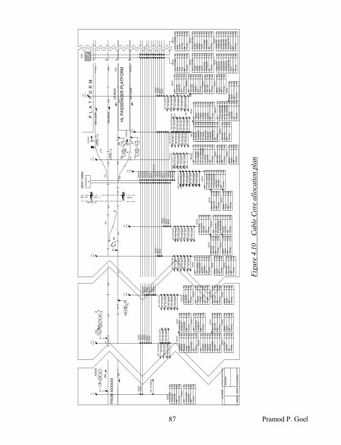
87 Pramod P. Goel
19C
X1
4C
20/2
1/2
2S
MR
4C
4C
4C
3C
SP
19C
TO
TA
L
3Y
R3
YR
4Y
R
19C
X1
4C
20/2
1/2
2S
MR
4C
4C
4C
3C
SP
19C
TO
TA
L
9Y
R1
0Y
R4
11Y
R
19C
X1
2C
20/2
1/2
2Y
SR
2C
2C
2C
15Y
NC
PR
5C
SP
3Y
RE
4D
RE
2C
5Y
RE
2C
15Y
R2C
CO
-2Y
RE
19C
TO
TA
L
19C
X1
2C
20/2
1/2
2Y
SR
2C
2C
2C
15Y
NC
PR
5C
SP
2Y
RW
3D
RW
2C
4Y
RW
2C
15Y
R2C
CO
-2Y
RW
19C
TO
TA
L
19C
X1
2C
2C
2C
2C
2C
2C
2C
5C
SP
19C
TO
TA
L
W/C
T
15D
EC
PR
15R
EC
PR
3/5
DE
CP
R3
/5H
EC
PR
3/5
RE
CP
RC
0-2
HE
CP
R
19C
X1
2C
2C
2C
2C
2C
2C
2C
5C
SP
19C
TO
TA
L
E/C
T
15D
EC
PR
15R
EC
PR
3/5
DE
CP
R3
/5H
EC
PR
3/5
RE
CP
RC
0-2
HE
CP
R
12C
TO
SA
3/5
12C
X1
2C
A3/5
HH
GE
2C
2C
6C
SP
12C
TO
TA
L 12C
X1
2C
MT
2C
2C
6C
SP
12C
TO
TA
L
A3/5
HH
PR
A3/5
DP
R
A3/5
DG
EA
3/5
HG
E
12C
X1
2C
A3/5
HH
GE
2C
2C
6C
SP
12C
TO
TA
L 12C
X1
2C
MT
2C
2C
6C
SP
12C
TO
TA
L
A3/5
HH
PR
A3/5
DP
R
A3/5
DG
EA
3/5
HG
E
6C
X1
2C
CO
-2T
PR
2C
3A
TP
R2C
SP
6C
TO
TA
L
2C
3/5
DG
E2C
2C
2C
2C
2C
3/5
HG
E3
/5R
GE
5U
GE
7C
SP
19C
TO
TA
L
19C
X1
CO
-2H
GE
4U
GE
2C
2C
2C
2C
2C
2C
6C
X1
3C
3C
NIL
SP
6C
TO
TA
L
BX
110V
NX
110V 6
CX
13C
3C
NIL
SP
6C
TO
TA
L
B24V
N24V
5C
SP
19C
TO
TA
L
3/5
DP
R3
/5H
PR
4U
HP
R
3A
TP
RC
O -
2T
PR
5U
HP
R
2C
MT
19C
X1
12C
X1
2C
S15
DG
E2C
8C
SP
12C
TO
TA
L
S15
RG
E
12C
X1
2C
MT
2C
2C
2C
18
AT
PR
4C
SP
15D
PR
15T
PR
TO
TA
L12C
6C
X1
3C
3C
NIL
SP
6C
TO
TA
L
BX
110V
NX
110V 6C
X1
3C
3C
NIL
SP
6C
TO
TA
L
B24V
N24V
6C
TO
S-1
5
2C
TO
15T
F
2C
TO
15T
R
2C
TO
18A
TF
2C
TO
18A
TR
12C
TO
LO
OP
12C
TO
PT
8L7
2C
TO
3B
TR
2C
TO
3B
TF
2C
TO
8bT
R
2C
TO
8bT
F
19C
X1
2C
MT
2C
2C
2C
2C
P8L
7N
WK
RP
8L
7R
WK
R8
bT
PR
03
BT
PR
9C
SP
19C
TO
TA
L 6C
X1
3C
3C
NIL
SP
6C
TO
TA
L
B24V
N24V
12C
TO
LO
OP
12C
X1
2C
SH
19
.ON
2C
2C
6C
12C
SH
19
.OF
FS
H1
9P
SP
TO
TA
L 19C
X1
2C
MT
2C
2C
2C
7C
2C
2C
SH
19H
PR
PT
8L9
NW
KR
PT
8L9
RW
KR
8aT
PR
3C
TP
RS
P19C
TO
TA
L
6C
X1
3C
3C
NIL
SP
6C
TO
TA
L
BX
110V
NX
110V 6C
X1
3C
3C
NIL
SP
6C
TO
TA
L
B24V
N24V
12C
TO
PT
8L9
2C
TO
8aT
R
2C
TO
8aT
F
2C
TO
18T
F
2C
TO
3C
TR
12C
TO
LO
OP
12C
TO
SH
19
19C
X1
2C
MT
2C
2C
2C
2C
2C
XX
SP
19C
TO
TA
L
2C
18
AT
PR
11
BT
PR
2C
TO
12b
TF
2C
TO
18T
F
2C
TO
11bT
R
12C
TO
PT
12
L14
12C
TO
PT
24
L23
2C
TO
03C
TF
12C
TO
LO
OP
2C
MT
2C
2C
2C
2C
2C
2C
5C
SP
19C
TO
TA
L
18D
PR
26H
PR
17D
PR
27H
PR
16H
PR
28H
PR19C
X1
19C
X1
2C
MT
2C
2C
2C
2C
2C
5C
SP
19C
TO
TA
L
2C
12b
TP
R0
5A
TP
R
2C
S18
RG
E2C
2C
2C
2C
2C
2C
2C
SH
28
HG
E1C
SP
SH
26
HG
ES
17
HG
ES
17
RG
ES
H27
HG
ES
16
HG
ES
16
RG
E
19C
X1
2C
S
18D
GE
TO
TA
L19C
6C
X1
3C
3C
NIL
SP
6C
TO
TA
L
BX
110V
NX
110V
6C
X1
3C
3C
NIL
SP
6C
TO
TA
L
B24V
N24V
12C
X1
2C
M/T
2C
2C
01
BT
PR
02
BT
PR
6C
SP
12C
TO
TA
L
2C
03C
TP
R2C
2C
04C
TP
R0
5B
TR
4C
SP
12C
TO
TA
L
M/T
2C
12C
X1
6C
X1
3C
3C
NIL
SP
6C
TO
TA
L
BX
110V
NX
110V 6C
X1
3C
3C
NIL
SP
6C
TO
TA
L
B24V
N24V
2C
TO
05A
TF
2C
TO
05B
TR
2C
TO
01A
TF
2C
TO
01B
TR
2C
TO
04B
TF
2C
TO
04C
TR
6C
X1
3C
3C
NIL
SP
6C
TO
TA
L
BX
110V
NX
110V
AS
MA
DE
SS
E(S
)D
ST
E
XX
XX
XX
P R
E P
A R
E D
B
Y
FO
R X
XX
XX
FR
OM
XX
XX
XX
UP
15
DN
P
A3
/4/5
C2
C2T
5R
L
19
03B
T
26
18
02A
T02B
T
DN
LO
OP
X - ING No: 395
3
('C'-CLASS)
LEVEL
S.M
.
21
15T
12
4
DN
MA
IN
04T
(AC
)
01T
(AC
)
03C
T18T
3B
T
4 3
8
8
8aT
11bT
FM
121
1
12bT
W19T
FM
UP
LO
OP
UP
MA
IN
B
01T
(AC
)
3A
T
WE
ST
CA
BIN
27
17
5
8bT
3C
T
04T
(AC
)
HL P
AS
SE
NG
ER
PLA
TF
OR
M18T
ST
OP
ST
OP
HL1
H F
F
L2
F HL3
F HL4
F HL5
F HL7
F HL6
F F
HL8
F F
F
L9
12C
X1
12C
X1
20C
X1
12C
X1
6C
X1
6C
X1
19C
X1
6C
X1
6C
X1
12C
X1
19C
X1
6C
X1
6C
X1
12C
X1
12C
X1
19C
X1
19C
X1
6C
X1
6C
X1
20C
X1
20C
X1
6C
X1
6C
X1
12C
X1
12C
X1
19C
X1
6C
X1
6C
X1
19C
X1
12C
X1
6C
X1
6C
X1
20C
X1
20C
X1
20C
X1
1X
2X
25
Sq.m
m
19C
X1
19C
X1
12C
X1
12C
X1
6C
X1
6C
X1
12C
TO
S-3
/5
6C
TO
R
6C
TO
CO
-2
2C
TO
CO
-2T
R
2C
TO
C2T
F
2C
TO
3A
TF
2C
TO
3A
TR
6C
X1
3C
3C
NIL
SP
6C
TO
TA
L
BX
110V
NX
110V 6C
X1
3C
3C
NIL
SP
6C
TO
TA
L
B24V
N24V
6C
TO
S-1
8
6C
TO
SH
-17
6C
TO
S-1
6
6C
TO
SH
-26
6C
TO
SH
-27
6C
TO
SH
-28
12C
TO
PT
24
L25
12C
TO
PT
12
L13
2C
TO
12bT
R
2C
TO
04C
TF
2C
TO
03C
TF
2C
TO
05A
TR
19C
X1
2C
MT
2C
2C
2C
2C
2C
5C
SP
19C
TO
TA
L
2C
PT
11N
WK
RP
T1
1R
WK
RP
T1
1L
10
NW
KR
PT
11L
10
RW
KR
01
AT
PR
02
AT
PR 6C
X1
3C
3C
NIL
SP
6C
TO
TA
L
BX
110V
NX
110V 6C
X1
3C
3C
NIL
SP
6C
TO
TA
L
B24V
N24V
12C
X1
TO
PT
.11
12C
X1
TO
I/L
10
2C
X1 T
O 0
1A
TR
2C
X1 T
O 0
2A
TR
2C
X1 T
O 1
1b
TF
P
L
A
T
F
O R
M
Fig
ure
4.1
0
C
able
Core
all
oca
tion p
lan

Indian Railway Signal Engineering Volume-II
88
iv) Current carrying capacity vis-à-vis load to be born by the cable conductors shall decide the number of conductors to be used in parallel for the load such as that of point machines being operated at longer distance i.e. 1000 metres or more, to avoid voltage drop and enabling point machine operation with full force as well as to cater for AC immunity if the point machine is provided in the area provided with 25 KV AC traction.
v) Power supply used by signalling system is 110 V 50Hz AC. vi) Technical limitations provide certain restrictions, i) such as outgoing main power
supply to operate any equipment in the distantly placed Apparatus Case or a Goomty, shall not to be put in the same cable on which return conductors are provided for
energising relay or equipment for which the power supply is provided. Similarly ii) under 300 V AC system of signalling only one signal lighting shall be provided in one cable, under 25 KV AC traction with unscreened cables. (300 V AC for signalling system has since been discontinued forthwith).
vii) All cables used for signalling system now are unscreened including the area provided with 25 KV AC traction imposing limits to provide cutting in relays at an interval of every 200 metres when incandescent lamps are used and 400 Meters when LED signals are used.
4.10.2 Allocation of the cables: One of the most important function is to connect all operated equipment in the field viz. signals, track circuits, point machines, interlocked crank handles, electric point detectors, level crossing gates, inter cabin slots, point to point telephones between Station Master & associated cabins etcetera with the commands generated at cabin or the Central Control Cum Indication Panel or the VDU with a mouse, through the copper conductor cables, needs: i) Cable to be laid between the two points i.e. operating device and the specified
operated unit. These points may be Relay Room at one end the Apparatus Case on the other end. Further connection to the relay or other operated equipment such as point machine or signals or the status of the equipment from site to the relay room shall be through derivation cable such as 8 Core or 12 Core or single Core multi-stranded conductor.
ii) Allocate type of cables required to be used such as for axle counters, 0.6 sq mm, 06 quad jelly filled cable shall be used for shorter distances within the station yard or 0.9 sq mm 06 quad jelly filled cable shall be used in the block section; Aluminium core conductor cable shall be used for carrying 220 AC power supply between the main source of power and the point of supply for the signalling system; using extra conductors in the signalling cable for working electric point machines placed at more than 1000 metres from the Point Controlling Relay (WCR), etcetera.
iii) Allocate number of conductors required for command to be transmitted. iv) Allocate capacity of the conductor to carry the required current. v) Allocate number of spare conductors to be provided in the cable concerned as per
provisions of paragraph 15.3.2 of SEM part –II, September-2001, which reads as- “Adequate spare conductors to a minimum of 20% of the total conductors used shall be provided for each main cable up to the farthest point zone, beyond this there should be a minimum of 10% spare conductors of total conductors used. No spare
89 Pramod P. Goel
conductors shall be required if the total number of conductors (in a cable) used is 3 or less. The spare conductors shall be provided on the outermost layer.”
vi) Economical distribution of type of cable balancing between main cable to be laid up to a given point, to make a junction point at an apparatus case, take off the derivation cable for feeding point machine, taking back the point indication relay feed, feeding power to track circuit or taking back the power for track circuit repeater relay etcetera and main cable to be continued further or terminated as the case may be.
vii) Working out length of each cable with similar or different cable configurations, including extra length of cable at each termination point to cater for minor shifting of apparatus case and re-termination needed, in future necessitating cutting of cable conductors for rearranging the termination positions.
viii) Group the cable to be put in minimum trenches following the cable routes as defined through cable route plan.
4.10.3 Preparation of cable Core Allocation plan: The cable core allocation plan for a yard shall depict on the signal and Interlocking plan modified to contain vital information about signals, track circuits, axle counters, crank handle apparatus cases etcetera where the cable shall be required to be terminated except the information not relevant to the cable core allocation such as, Aspect Sequence Chart, Special notes, Gradients etcetera: i) All apparatus cases, meant to house track circuit feed equipments and to house track
circuit relays, for housing relays to control signals, Junction Boxes for point machines, Electronic Junction Boxes (EJB) for the axle counter, shall be depicted at the required position indicating the equipment/termination.
ii) Indicate all trenches containing type and number of cable laid within the given trench. iii) Workout total length of each type of cable, covering 10% extra of the total length for
lying loosely in the trench, added with the extra length of another 05 metres at each end of termination.
iv) Fill up details in the box associated depicting the usage of each core with each such cable and each cable’s length along with the available spare conductors.
A typical sample cable core allocation plan is placed as figure numbered 4.10.3 The cable Core Allocation plan shall base upon the Cable Route Plan existing and proposed, without deviations for procuring and laying cable, judicially and economically. 4.11 Cable Core Termination Chart: Once the cable route is identified and cable core allocation plan has been prepared, both ends of the cable have to be terminated. The termination shall be between relay room of the place wherefrom the commands are generated such as Multiple Cabins, End Cabin, Central Cabin or the Control Cum Indication Panel/VDU and terminated at the Apparatus case connecting the operated equipment viz. signal or point machines, ii) communicating status of track circuits, point indications, level crossing gate from site to the relay room and between cabin to cabin for inter-cabin slotting. Here the cable to be terminated is referred to Cable carrying 1.5 sq mm area of cross section conductors for signalling circuits. 2.25 sq mm copper conductor Cables for power supply and 0.6 sq mm Jelly Filled Cables for Axle counters are also laid between cabins, transmitting commands and

Indian Railway Signal Engineering Volume-II
90
receiving status from the field. Accordingly the cable shall be terminated at Cable Termination Rack (CTR) at relay room and Apparatus case or Junction box. The cables shall be laid in the trenches leading from the main relay room/Station Master’s Room, to the apparatus cases or Goomties. The trenches made for Main Cables shall have different routes into which the cables shall be laid in conformity to the Cable Core Allocation Plan. For example if the Signal relay HR energised in Station Master’s relay room is to be repeated in the Apparatus Case for signal number 3/4 [figure 4.9 for SIP], the output of 3/4 HR in the relay room shall be connected to the cable laid up to the apparatus case meant for signal number 3/4. 4.11.1 Preparation of Cable Termination Chart: Different practices are in vogue for cable termination, depending upon requirement viz. cable terminated on, i) Main Distribution Frame (MDF), ii) Cable Termination Rack (CTR) and ii) Composite Rack (CR). In either of the system the cable is required to be connected onto the MDF/CTR/CR which is at the relay end and at the Apparatus case, related to the operated equipment such as signal lighting, point operation, level crossing gate control etcetera. Similarly for feeding the status of the equipment such as track occupancy, point set and locked etcetera, from the apparatus case/Goomty to the concerned relay room connected onto the MDF/CTR/CR. This arrangement shall be in strict conformity to the Cable Core Allocation Plan. The Cable Core Allocation Plan so designed shall be made out in the form of a chart, for laying cables between each of the Relay Room and the Apparatus cases/ Goomty. It is pertinent to note that the allocation of each conductor of each cable shall be maintained similar for all stations of a section where the system of signalling is same, for easy identification of the cable conductor for a given function, for example, if function 3DR is connected, for up home signal on CTR1/23 & CTR1/24, this cable core allocation shall be maintained same for all stations in the given section, under the same system of signalling. 4.12 Main Distribution Frame; Cable Termination Rack; Terminals and Fuses: Main Distribution Frame (MDF) is in two sections, upper being distribution of power supply for the system and lower being for cable termination. Cable Termination Rack (CTR) is meant exclusively for termination of the cables. The MDF, is made of Mild Steel angle iron frame onto which a sheet of insulting material, mostly Hylam Sheet is fixed with nuts and bolts. The frame is erected through anchor bolts grouted on the ground with an insulator in between the ground and the frame. The Composite Rack also made of mild steel angle iron frame and is used for accommodating relays and cable termination on the same rack, while the power distribution is done on the Main Distribution Frame. 4.12.1 Main Distribution Frame: On stations where the power supply and the cable

91 Pramod P. Goel
termination can be accommodated on one and the same distribution frame, it is sectionalised in two parts, upper being used for Bus-bars with fuses for different power supply positive potential, associated with a corresponding bus bars with negative /neutral polarity. The second section is used for cable termination. The MDF has been shown splintered in the figure 4.12.1 so as to accommodate within this page. 4.12.1.1 Power supply distribution: The Power supply for the station may require AC and DC with voltages different for different equipment such as 220 V AC transformed to 110 V AC for signal lighting and track feed chargers. Supply for signal lighting shall be terminated at the bus bar on MDF. If the station falls within the section energised on 25 KV AC traction, the distance limitations shall be complied by providing two such separate transformers for <200 metres and >200 metres. The DC power shall be required for energising relays, block bell and for line circuit of the Block instrument. This may be achieved by providing independent battery Chargers of requisite capacities supported by the Battery banks or by using Integrated Power Supply (IPS), terminated on the MDF bus-bar. Each such power supply shall be derived for functions through fuses connected to bus-bar at one end with to the circuit/function on other end. The lower section of the MDF is used to terminate the cables on ARA Terminals, leading to outside functions in accordance to the Cable Core Allocation Plan. See figure 4.12.1 for Main Distribution Frame. 4.12.1.2 Cable Termination: Cable is terminated on the lower section of the MDF on left stud of the ARA Terminals and the wires associated to the interlocking circuits are connected to the right stud of the terminal. It may be required to extend power supply BX/NX 110 or B/N 24 to the field equipment/ apparatus cases/Goomty, connected on the Right hand stud of ARA terminals, to be extended through the Left hand terminals on the cable. Rules for maintaining spare conductor’s requirements for each cable, to be observed strictly, and are required to be terminated in sequence to the rest of the cable.
110V AC(NX)N-24V [INT]
2827262587654321
SP
AR
E
SP
AR
E
110V AC(BX)
A3/4
HH
GE
SP
AR
E
45
44
45
DG
E,R
GE
15D
GE
,RG
E
18D
GE
,RG
E
17,1
8,3
/4E
TS
R
C2E
EU
UY
R
RE
CP
R,U
EC
PR
3/4
,15
DE
CP
R
FR
1,F
R2
NJP
R,R
JPR
120E
JR,
17,1
8,2
02
1N
R,R
R
B-24V [INT]
2827262587654321
3
12
11
10
9
8
7
6
5
4
44
G1
2
3
4
5
6
7
8
9
10
11
12
13
14
15
16
2
1
16
15
14
13
12
11
10
9
8
7
6
5
4
3
2
1BA
1 1
2C
TO
DIS
TA
NT
L-1
1
A3/4
HHGE
A3
DGE
A3/4
HGE
1 1
9C
TO
L-1
0
1 1
2C
TO
DIS
TA
NT
L-1
1
MT
A3/4
HPR
3
DPR
3/4
HPR
4
UHPR
C2
HPR
CO2
TPR
3/4
ATPR
SP
SP
MT3/4
BTPR
1 1
2C
FR
OM
L9A
×
×
×
×
1 6
C T
O L
-6C
×
BX
110V
NX
110V
B-24V
N-24V
K-2
NWKR
1 6
C T
O L
-6C
×
MAIN DISTRIBUTION FRAME
Figure 4.12.1 Main Distribution frame

Indian Railway Signal Engineering Volume-II
92
4.12.2 Cable Termination Rack: In situations when the cable is required to be terminated on Cable Termination Racks (CTRs) more than one, the CTRs shall be numbered as CTR-1, CTR-2, CTR-3 etcetera, as per requirement. In this case an independent MDF shall be used for power supply distribution exclusively. Each such CTR shall maintain same system of numbering of terminals as that for MDF as discussed in preceding paragraph. Independent Relay racks shall also be provided. in order to connect the Interlocking Circuits, inter and intra rack wiring shall be done. 4.12.2.1 Composite Rack: When Under the system of Main Distribution Frame and the Cable termination racks are used independently, the plug-in type relays are mounted on independent rack (shelf type relays have been phased out), onto which the wire connections are between relay & relay and relay & MDF. However another arrangement in use is Composite Rack. The rack is partitioned in two parts upper being used for mounting relays and the lower section being used for cable termination. This sometimes simplifies the wiring also. On upper section of the Composite Relay Rack, mild steel galvanised square bars are fixed on to the frame of the Rack using bolts and nuts through holes made in the ends of the square bars. Holes are also drilled in the square bars to bear the bases for plug-in type relays. See figure 4.12.2.1 for Composite Rack. 4.12.3 Placement of Terminals: Either of the two systems i) terminals placed horizontal forming columns [Figure 4.12.1 for MDF & figure 4.12.2.1 for Composite Rack], and ii) terminals placed vertically, formingh rows [Figure 4.13.1], is adopted for fixing the terminals on the Hylam sheet. Numbering of the rows and terminals shall be done as: i) The row or the column as the case may
be, shall be numbered alphabetically A, B, C and so on.
ii) Each such row or the column, as the case may be, shall limit itself to one cable only.
iii) However, in case two or more cables can be accommodated in one column/row under same alphabetical number, the next cable shall start after leaving a gap of at least one terminal for identification between each cable.
iv) Each terminal shall be numbered as 1, 2, 3 as suffix to the row or column number of cable termination such as CTR A-1, CTR A-2, CTR A-3 etcetera for row or column
8C
DE
RIV
AT
ION
CA
BL
E8
C D
ER
IVA
TIO
N C
AB
LE
B
3
12
11
10
9
8
7
6
5
4
1
2
12
11
10
9
8
7
6
5
4
3
2
1A
1 1
2C
TO
DIS
TA
NT
L-1
1
A3/4
HHGE
A3
DGE
A3/4
HGE
1x19
C T
O L
-10
3
DPR
3/4
HPR
4
UHPR
SPARE
×
BX
110V
NX
110V
B-24V
N-24V
K-2
NWKR
1
2
3
4
5
6
7
8
9
10
11
12
19
Figure 4.12.2.1 Composite rack using
terminals horizontally forming columns

93 Pramod P. Goel
being ‘A’ and for row/column ‘B’ as CTR B-1, CTR B-2, CTR B-3 etcetera. When more than one CTRs are used, the numbering for terminals on the rack number ‘1’ shall be CTR 1A-1, CTR 1A-2, CTR 1A-3, etcetera, where suffix ‘1’ to CTR represents the rack number; ‘A’, ‘B’, ‘C’ etcetera Alfa letters represent row or column numbers; and numerals ‘1’, ‘2’, ‘3’ represents terminal numbers.
v) The alpha numeric numbering shall start de-novo with the next column or row.
vi) The alpha-numeric number of the conductor of the cable at its other end in other cabin or Apparatus case, say ‘B-1’ shall be numbered same as that of ‘B-1’ for easy identification of correspondence, to the extent possible.
4.13 Terminal and the connection: Terminal largely used for 1.5 sq mm area of cross section copper cable conductor has a two brass studs, with their heads moulded with the Bakelite base. Each such stud is threaded and has four nuts with two washers in between the middle two nuts, to hold the copper conductor of the cable, tightly [Figure 4.13(a) & 4.13(b)]. The disconnecting link, with slotted hole on its left/main cable end and a slotted opening on the other end is put between pair of middle two nuts and tightened with another nut with top one being the Check Nut. The cable conductors are wrapped around the brass stud in single turn, keeping in between two washers and nuts on both studs. The connection between the cable conductor & the interlocking circuits shall be made through the Disconnecting Link placed above the cable connection to avoid disturbing the cable connections while connecting or disconnecting the signalling circuit, by the Link. 4.13.1 Practice of using the terminals
horizontal and vertical: The Bakelite base of the terminal has one hole used to fix it with nuts and bolts onto the Hylam sheet. The disconnecting link is to isolate the cable with the internal circuit. These terminals are also available in 6/8 way moulding. As the ARA terminals are placed horizontally as depicted in the figure 4.12.2.1 appearing in Composite Rack, placed one below the other forming columns. In this case as the link is loosened, it shall hang vertical about the left stud making contact to the terminal stud below, thereby causing both terminals short circuited. In case of
Figure 4.13 (a) Disconnecting type
ARA terminal
C
121110987654321
1 2 3 4 5 6 7 8 9 10 11 12
B
1211109876543
A
21
Figure 4.13.1 Terminals placed
vertically to form rows
Figure 4.13(b) Terminal’s
Disconnecting Link

Indian Railway Signal Engineering Volume-II
94
placing the terminals vertical forming rows [figure 4.13.1], when the terminal is loosened it shall hang by itself without interfering with the adjoining row eliminating the short circuit. Both the practices are in vogue. 4.13.2 Terminals used with Electronic Interlocking: With the advent of Electronic Interlocking, Low current circuits are used with the main cables being terminated to communicate commands and information to and from field units. For such purposes Polyamide Disconnecting type Composite Terminals are being used. The terminals are mounted on a rail, making it easy to slide in and slide out while at the same time, are found useful for installation having space constraint and high wiring density. Terminals have funnel shaped wire entry hole which guides wire perfectly into the clamp even in difficult and congested places for wiring [figure 4.13.2]
Figure 4.13.2 MTK polyamide disconnecting type
Composite terminal set.(left one manufactured by M/s Phoenix Contact)
4.13.3 Tag Blocks used for Wiring Siemens Designed Circuits: The Bakelite based block with 60 paired tags (120 tags) and 100 paired (200) tags are mounted on the top of the relay rack. The connectivity shall be as detailed below: i) The wire runs between the terminal at the main distribution frame and the relay rack
terminated and soldered on the incoming tag and between the paired second tag to connect the function i.e. the coil or contact of the relay. This way the connectivity shall be from the terminal of the MDF/CTR and the function shall be through Tags.
ii) Between relay rack and relay rack for inter rack wiring through tags. 4.14 Fuses and Micro Circuit Breakers
4: The bus-bar is connected to the positive
terminal of the power supply. Fuses with their cap connected with the lug eye are connected to the positive bus-bar through washer and screw at one end and to the circuit at the other end. HRC fuses are mounted on the Bakelite base fixed on the MDF to which the cover crying the fuse cartridge is inserted to make the connection through. Micro Circuit Breakers (MCBs) are
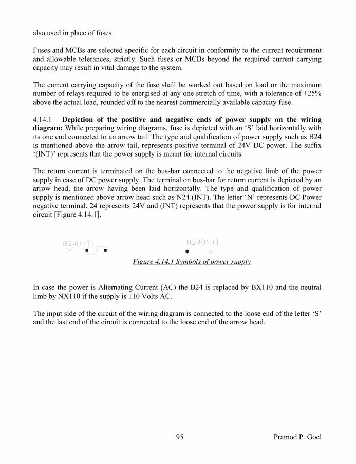
95 Pramod P. Goel
also used in place of fuses. Fuses and MCBs are selected specific for each circuit in conformity to the current requirement and allowable tolerances, strictly. Such fuses or MCBs beyond the required current carrying capacity may result in vital damage to the system. The current carrying capacity of the fuse shall be worked out based on load or the maximum number of relays required to be energised at any one stretch of time, with a tolerance of +25% above the actual load, rounded off to the nearest commercially available capacity fuse. 4.14.1 Depiction of the positive and negative ends of power supply on the wiring
diagram: While preparing wiring diagrams, fuse is depicted with an ‘S’ laid horizontally with its one end connected to an arrow tail. The type and qualification of power supply such as B24 is mentioned above the arrow tail, represents positive terminal of 24V DC power. The suffix ‘(INT)’ represents that the power supply is meant for internal circuits. The return current is terminated on the bus-bar connected to the negative limb of the power supply in case of DC power supply. The terminal on bus-bar for return current is depicted by an arrow head, the arrow having been laid horizontally. The type and qualification of power supply is mentioned above arrow head such as N24 (INT). The letter ‘N’ represents DC Power negative terminal, 24 represents 24V and (INT) represents that the power supply is for internal circuit [Figure 4.14.1].
Figure 4.14.1 Symbols of power supply
In case the power is Alternating Current (AC) the B24 is replaced by BX110 and the neutral limb by NX110 if the supply is 110 Volts AC. The input side of the circuit of the wiring diagram is connected to the loose end of the letter ‘S’ and the last end of the circuit is connected to the loose end of the arrow head.

Indian Railway Signal Engineering Volume-II
96
4.15 Track Circuit Allocation plan4: The route may be operated by i) Diesel or Steam
traction, ii) the AC traction, or iii) DC traction. If the route is operated by Diesel or Steam traction (still used in some sections), the DC Track Circuits and as an alternative, Audio Frequency Track Circuits (AFTC), Axle Counters or uneven waveform track circuit may be provided, using both the rails. However if the AC traction is used for running the trains, one rail is essentially required for traction return current, connected through and terminated at the traction feeding post, while at the same time DC track circuits shall essentially be required to be used. In case AFTC is proposed to be used both the rails shall be required to be used with Impedance bond at each junction or termination of the track circuit. In case of DC traction, only the AC track circuit shall be provided. If axle counters are used to monitor the track vacancy, the track shall be used only to clamp the Transducers without affecting the rails otherwise if no track circuit is superimposed on the rails. In any case the portion of the track within in the Station Section and in the Block Section shall be depicted in two lines, representing two rails of the track, along with points and crossings, showing Rail Insulation Joints (RIJ) and traction bonds if traction is other than Diesel or Steam loco. 4.15.1 Preparation of Track Circuit Allocation
Plan4: Track vacancy monitoring is done by the Track
Circuits superimposed on the rails of the track or by using Axle Counters. Accordingly Track Circuit allocation plans are designed as discussed in ensuing paragraphs: 4.15.1.1 Track Circuit Allocation Plan for DC & AC
track circuits: In case of DC & AC Traction, one rail is used to facilitate traction return current which is also shared by the DC or AC track circuits as the case may be. The current flowing through the rail selected for traction return, in case of 25 KV AC traction, is 300 Amperes by one loco each. To allow such a heavy return current to
18/1
9C
20
18 19
14
6
4
RA
IL L
AV
EL P
AS
SE
NG
ER
PLA
TF
OR
M
7
B
WE
ST
C
AB
IN
CO
-20T
7T
19A
T13aT
4B
T13bT
11
10a
10b
13b
13a
3
5
ST
OP
19B
T
10bT
02C
T
03B
T03A
T
04A
T
11T
10aT
01C
T9T
02B
T
01B
T
HIG
H L
AV
EL P
AS
SE
NG
ER
PL
AT
FO
RM
ST
OP
Fig
ure
4.1
5.1
T
rack
cir
cuit
all
oca
tion p
lan

97 Pramod P. Goel
flow, mild steel cross bonds are used to connect the rails enroute to be earthed at the power feeder post wherefrom the power for the traction is fed. Accordingly the rails common to the AC traction return current and negative polarity rail of DC track circuits are shared. Fish plated rail joints are also electrically strengthened by providing MS Flat, traction bonds for traction return current and by GI bond wires for track circuit current to flow for DC track circuits. It may be observed in the figure 4.15.1 that the rail connected with positive polarity of the power supply is shown by thick line and other rail shown in thin line is connected to the negative polarity of the power supply. The end of the track circuit connected at power supply is shown by a circle with (+) inside and the end shown with an arrow is connected with relay end. The junction of any two track circuits provided with Rail Insulation Joint (RIJ) is shown by small line drawn perpendicular to the rail. As and when any track circuit which does not adjoin any other track circuit is shown by half bracket similar to the letter ‘L’ cutting the line shown as the rail. The direction of the half bracket on the plan across the rail show the track circuits within. In case another track circuit is provided after a gap with the adjoining track circuit(s), it shall begin with a half bracket showing such as to enclose the new track circuit. Such a situation may arise when it is not possible to provide a track circuit on the section of track laid on steel sleepers causing both rails of the track to short circuit. To cover such portion of track to be monitored for track occupancy the Axle Counter shall be provided, transducers of which shall be mounted on rails within the zone of track circuits on both the ends to ensure that no zone of the track remains unmonitored. Two adjoining track circuits shall be connected with staggered polarity i.e. the polarity of the power supplied to one track circuit say 19AT on one end of the RIJ shall be staggered with the adjoining track circuit numbered 19BT [Figure 4.15.1]. As in case of leakage of RIJ the adjoining track circuit is likely to get energised by the feed of other track circuit creating unsafe conditions. 4.15.1.2 Track Circuit Allocation Plan for Audio Frequency Track Circuit
4: Audio
frequency Track Circuits although superimposed upon the rails, do not have Rail Insulation Joints. However in case of traction being AC the traction return current is made to run through both the rails of the track. To ensure flow of current does not create potential difference
Fig
ure
4.1
5.1
.2 T
rack
Cir
cuit
all
oca
tion P
lan f
or
AF
TC

Indian Railway Signal Engineering Volume-II
98
between the rails, Impedance bond is provided on each Electrical Separation Joint. With the advantage of each track circuit covering larger length and also fractured rail getting monitored (to limited extent), AFTC is largely used for monitoring block section [figure 4.15.1.2]. RX & TX mentioned on the allocation plan represent receiver and the transmitter respectively, added by arrow directing towards output from the track to receiver and the arrow directing towards the track from the transmitter track. The frequency used for the given track circuit is also mentioned on the plan. The Electrical Separation Joint is depicted by the ‘equal to’ symbol ‘=’ placed right angles to the line representing the track. 4.15.1.3 Track Circuit Allocation Plan for Axle Counters: Axle Counters in use are ‘Analogue’ and ‘Digital’.
i) Analogue axle counters, when used, have to be provided within the zone of Trolley Suppression Track Circuit, Transducer’s mounted at least 2.5 rail length within the Rail Insulation Joint (RIJ) This eventually means that a trolley suppression track circuit onto which by-directional movement is in vogue, shall be not lesser than 5 rail lengths measured as 5 x 13= 45 metres. On double line section where traffic is unidirectional, this length of the track shall be limited to three rails. In this case a pair of Transducers shall essentially be required to cover one track vacancy monitoring section. ii) Digital Axle counters: With the advent of the Digital Axle Counters the trolley suppression track circuit feature is no more required. Such Axle Counters are Single Section and Multi Section. Single Section Digital Axle Counters are used in general for monitoring block sections and do not require Central Evaluator as the detection point in this case is competent to function as evaluator as well. Accordingly for double line section monitoring of the Block Sections shall require two such independent Single Section Digital Axle Counters. In case of Multi Section Digital Axle Counters the Axle Detectors are placed common to adjoining track sections, which are connected to the Central Evaluator, which evaluates and monitors each section for track vacancy. The detection point’s arrangement for a sample yard is appended as figure number 4.15.1.3.
Figure 4.15.1.3 Multi section Digital Axle Counters Detection points in yard

99 Pramod P. Goel
4.16 Track bonding plan: Once the track circuits are allocated, the feed and rely ends of the track circuits & connections to the rails are earmarked and location boxes to house the feed end equipment along with battery charger are marked on the plan. Another Apparatus Case shall be provided to house the Battery bank required to feed power to the track circuit [Figure 4.16]. 4.17 Rod Compensation plan: Point and lock are operated by 33 mm diameter forged iron rod used as media of transmission between lever and the point or lock. No compensator is required for the rod connected between lever and the point or lock up to the length of (40') 12 metres. However the Compensation Plan shall be prepared when the length of the rod is more than 12 metres, for the entire length of the rod run between the outer edge the cabin wall from where the rod is taken out and the arm of adjustable crank. Refer Rod Compensation Plan paragraph & figure of Indian Railway Signal Engineering Volume-III Mechanical Signal Engineering section-1 of this binding. 4.18 Apparatus Case wiring diagram: Apparatus case is used for housing the i) Controlling relays for signal, ii) Controlling relay for point machine, iii) Track feed equipment, iv) Track circuit relay end equipment, v) Junction box, vi) Battery bank for track circuits, vii) Equipment for single section digital axle counter. In any case the apparatus case shall also work as junction box except when provided at the last signal of the station. The copper conductor cable for signalling system is marketed in 500 metre length on each drum. Accordingly the continuity of the cable is made by terminating ends of each cable on a Junction Box; each conductor of the cable on terminal with a disconnecting link maintaining symmetry by conductor to conductor and layer by layer for maintaining seamless continuity between relay room and last Apparatus Case. The cast iron Junction Box is mounted on angle irons embedded within cement, sand and concrete aggregate is meant exclusively to work as junction without any accommodation for housing an apparatus. The Apparatus case is partitioned in two sections, the upper one with horizontal wooden base to house the equipment and lower one with a Hylam sheet vertically fastened with the frame of
Fig
ure
4.1
6
T
rack
bondin
g p
lan

Indian Railway Signal Engineering Volume-II
100
the Apparatus Case to bear terminals for, i) making the cable conductors through, ii) terminating the cable, the apparatus case being meant for last signal of the station and, for iii) making some conductors to pass through the location Box and some conductors to be connected to the circuit meant for signal lighting or point control relay operation or track circuit feed or track relay. Accordingly the wiring diagram for each apparatus case shall be purpose based. Refer figure 4.18(i) which shows the Terminals provided in columns marked as ‘A’ and ‘B’. The column ‘A’ is meant as junction for carrying some conductors through to next Apparatus Case and terminals on column ‘B’ are for derivation cable connection. The main cable conductors terminated on terminals CTR A1/1 to CTR A1/12 are to extend the circuits to next Junction Box/Apparatus case. Remaining Conductors terminated on terminals CTR A13/1 to A20/1 are used for lighting signal number 23. The derivation cable is terminated on CTR B1/2 to CTR B8/2 at the apparatus case and to the terminal strip at Junction Box of the signal post of the colour light signal number 23. Four conductors of the main cable are kept spare and 2 conductors of derivation cable are left unused. Assuming that the Apparatus case is meant for signal number 23 having red, yellow and green aspects, and also that the incoming cable connected at terminal numbers CTR A13/1 & CTR A14/1 carry command for energising relay 23-DPR to be connected to R1 & R2 of relay 23DPR. CTR A15/1 & CTR A16/1 carries 110 V AC DPR. CTR A17/1 & CTR A18/1 carry command for energising relay 23-HPR to be connected to R1 & R2 of relay 23-HPR and CTR A19/1 & CTR A20/1 carry 110 V AC HPR [figure 4.18(i)]. Refer figure 4.18(ii) for Wiring Diagram in the apparatus case. As the 23 DPR is energised, the 110V AC 23DPR shall get extended through pickup contacts A1/2 & B1/2 of 23 DPR, to illuminate the green aspect signal lamp through CTR B1/1 and CTR B2/1. If the relay 23HPR is energised instead of 23 DPR, the 110 V AC 23HPR shall get extended to illuminate the yellow aspect signal lamp through CTR B3/1 and CTR B4/1. However if the 23 HPR is not energised the same power shall get extended to the red aspect lamp of the signal through its back contacts B5/6 & B7/8.
Figure 4.18(i) Apparatus case with
partition

101 Pramod P. Goel
The other arrangement of terminating the cable is providing terminals in rows placed vertically. Refer figure 4.15(iii) which shows one terminal. The link is a flat brass strip with hole on its left hand and opening on the right hand with a slot in between. The hole is also slotted so as to enable the link slide leftwards one end it may be appreciated that as the link is loosened. 4.19 Interlocking Wiring Diagram: The interlocking, in case of mechanical system of signalling, is achieved by preparing an Interlocking Table and then based upon the same, preparing an Interlocking Chart. The Wiring Diagram is prepared by converting the contents of the Selection Table into Circuit Diagram to achieve interlocking under electrical system of signalling. There may be situation where the signalling system may be hybrid using mechanical system of signalling operating system by levers and interlocking through mechanical as well as electrical use. In such cases of hybrid interlocking the mechanical system of signalling is intermeshed with electrical system of interlocking especially in case where the colour light signals are used operated by levers. Usually in such cases complete mechanical interlocking is provided in the lever frame while the electrical system of interlocking is complimentary. The wiring diagram in such cases replicates some important functions and covers other functions such as track circuits, electrically operated points, approach and back locking etcetera. The Interlocking Wiring Diagram for electrical system of interlocking is provided to cover entire station concerned. 4.19.1 Preparation of Interlocking Wiring Diagram: The Interlocking Wiring Diagram is prepared based on the Interlocking circuits. For this purpose requirement of relays is assessed and a Relay Rack chart is prepared. The allocation of relays on the Relay Rack Chart is based on consideration of a) minimum length of wire used to i) keep the resistance of each circuit between fuse and the negative/neutral limb is kept least, ii) for economical reasons, iii) easy location of wiring, iv) neat and clean bunching, v) least time in wiring, vi) easy identification of relays on relay rack by judicious grouping. In a system of Route Relay Interlocking or Panel Interlocking the basic circuits are identified as i) Signal Button circuits, GNRs, ii) Route button circuits, UNRs, iii) Point Button circuits, NRs, iv) Interlocking circuits LR, v) Point Operation and Control Circuits, NWRs & RWRs or NURs & RURs along with point indication circuits, NWKRs & RWKRs, vi) Point Locking circuits, WZRs, vii) Route Checking Circuits, UCRs, viii) Route locking circuits, ASRs, ix) Signal control circuits, GRs/HRs/DRs, x) Signal lighting circuits, UECRs, xi) Indication and lamp checking relay circuits GECRs; and other peripheral circuits viz. xii) Crank Handle Control circuits CH:NPRs, xiii) Emergency Signal replacement circuit, EGGRNZR, xiv) Inter-cabin
Figure 4.18(ii) wiring diagram for
apparatus case
Indian Railway Signal Engineering Volume-II
102
slotting circuits, YRs, if the system is end/multi cabin controlled, xv) Calling-on signal control circuit, xvi) Time Element relay circuit,JR, and xvii) Counter circuits. 4.19.1.2 Relay Rack Chart for ‘Q’ series relays: a) All such relay groups in-turn entail keeping each circuit group viz. i) Buttons, i.e. GNRs, UNR, WNRs, WRRs, ii) LRs, iii) WZRs, iv) WLPRs & EWNPRs, v) Point control & operation viz. NWR, RWR, or NUR, RUR, and UZRs, vi) Route checking viz. UCRs, vii) Route Locking viz. ASRs, viii) Time element viz. JR, NJPR & RJPR, ix) Track circuit relays, viz. TRs and TPRs, x) Crank Handle control viz. CH:YPRs & CH: NPRs & Z(N)Ls, xi) YR if inter-cabin slotting is there, xii) Signal relay circuits viz. GRs, HRs & DRs, xiii) Signal lighting, and xiv) Indications viz. NWKRs & RWKRs for points, ECRs for signals, route light indications, signals, points, flasher relay, Chrank Handle on Control cum Indication panel etcetera, grouped together.
Considering ‘Q’ series relays are used: a) All such groups are placed in such a way that the length of wires is kept to be bare
minimum. b) Repeater relays shall be worked out before proceeding. c) The contact numbers A ½ & D ½ of each relay shall be kept reserved for energising
repeater relay as and when required and for connecting Data Logger, respectively. d) One type of relays shall be used for one type of group Viz. all GNRs if kept QN1 8F-
8B, same relay configuration shall be used for all GNRs, if 12F-12B QN1 relay is used for NWKRs & RWKRs all NWKRs & RWKRs in the group shall be of same contact configuration.
e) Under no circumstances all contacts of any relay shall be filled keeping at least one contact free, instead a repeater relay shall be mounted on the relay rack.
f) Under any eventuality if a relay be it repeater or otherwise, is to be inserted in between any relay group at least one space shall be kept unused as space after each group of circuits is completed besides one space may be kept clear after each 5th relay in each group.
The relay rack chart shall be prepared accordingly, depicting as the relays shall be placed on the relay rack, along with the relay details as, i) Relay rack position, ii) Name, iii) Contact configuration, iv) AC immunity if applicable. The relays and relay groups shall be planned to keep economy of wire, keeping minimum number of racks, easy identification, and time consumed in carrying wiring. It is pertinent to note that with the relay contacts configuration changing some contacts get changed from pickup to back and vice-versa disturbing the interlocking arrangement from wanted to unwanted. To ensure this not to happen, the base of the relay bears three sets of six holes to accommodate corresponding pins of the relay. At any stage each relay shall have at least five such holes opened rest having been blocked configured in such a way that the relay pins corresponding to the specific configuration shall only be inserted into the base to avoid provision of a relay with configuration different to the one allocated. The configuration shall never be tempered by filling or drilling the holes in base to accommodate corresponding relay,

103 Pramod P. Goel
being highly unsafe. 4.19.1.3 Contact Analysis for ‘Q’ series relays: once the relay rack chart is finalised, the corresponding Contact analysis chart shall be prepared. The Contact analysis chart shall be prepared on specific format depicting i) The relay rack position, ii) Name of the relay, iii) Contact configuration, iv) Each contact depicted with reference to contact numbers, vi) Each back contact identified by filling the top right corner making a triangle for easy identification. A) Fundamentals of preparation of Contact analysis: making contact analysis is a fine job, time consuming and observing immense alertness. Accordingly: a) To avoid the repetition, preparation of contact analysis shall be initiated only after the circuit diagram has been completed and associated each sheet has been numbered with the sheet number and total numbers of the sheets in the complete set of circuit diagram. Any change in sheet numbering arising out of addition or subtraction of sheet for any reason what so ever shall cause the contact analysis to be carried out partially or fully, de-novo. Such sheets to be added may be numbered with suffix A, B, or C as the case may be, to the sheet number to which it is associated. b) The repeater relays shall also be numbered before start of the of contact analysis, having worked out the total number of contacts required to be used including spare contacts for, i) A 1/2 Repeater relay ii) D 1/2 Data Logger, iii) at least one contact left spare to be used in case of emergency, iv) Repeater relays shall be created for relays originally having small number of contacts such as ECRs having only four pickup and four back contacts. c) Relay contact numbered in one circuit shall be used in one group of circuit and shall be maintained same even by creating a repeater relay unless the relay is very lightly loaded such as in case of HR circuits if A 1/2 of corresponding 3ASR is used for energising 3HR then A 1/2 shall be used of other, say, 4ASR in the circuit to energise 4HR. This is essentially required for easy and fast localisation of fault in cases when the train is being detained for the reason of a failure. The contact analysis shall be filled in the hard copy or directly on the soft copy of the circuit diagram for each relay one by one and in the format of contact analysis simultaneously, allotting the i) relay rack position, ii) contact number against the relay in the circuit and iii) sheet number onto which the given circuit has been provided; In case more than one contact is used of the same relay, in one and the same sheet, the contact numbers, in the format of the contact analysis, must be filled in.
It is pertinent to note that extreme care shall be observed to ensure that no contact of a relay is
duplicated, resulting in loss of time while carrying out wiring as well as if the mistake is
allowed to pass on, at the time of location of the fault.
See Indian Railway Signal Engineering Volume IV chapter-V, by the author same as that of this
book, for the sample format of relay rack chart and the contact analysis.
4.19.1.4 Fuse analysis & negative/neutral limb: Once the interlocking wiring diagram is completed, provision of the fuse on the positive terminal in case of DC power supply and BX in case of AC power supply is determined. Similarly the negative DC or the NX (neutral terminal

Indian Railway Signal Engineering Volume-II
104
of AC power) terminal is determined. Usually each negative/neutral shall correspond with each other with the same number unless the circuit warrants additional negative/neutral terminal to one fuse. The interlocking wiring diagrams as may be grouped circuit-wise, i) internal and external circuits when the AC traction in the section/station prevails, shall be isolated resulting in separate fuses, ii) one common fuse shall be used for a circuit with one relay or energising one relay only out of more than one in the same circuit, each relay requiring same voltage & current for operation, iii) Circuits for lighting each signal, iv) circuits energising relays more than one, v) circuits for time element relay, vi) indication lighting circuits, vii) circuits for counters, viii) point control i.e. WCR energising circuit requiring heavy initial current to the tune of 6 amps, ix) Block Instrument line circuit. All such fuses shall be tabulated with the i) name of the circuit such as 3HR or 4 HR or 3ASR etcetera, ii) power supply type i.e. AC, DC, iii) voltage of power supply such as 24V, 60V or 110V, iv) corresponding current rating such as 1 amp, 2 amp, etcetera including the allowance, depending upon load of the circuit, mentioned against each. The negative terminal shall also be tabulated numbered against each such fuse. The interlocking wiring diagram shall cover the voltage and type of power supply number against each such fuse. The negative/neutral terminal number along with the type and power shall be provided corresponding to each negative/neutral terminal. The wiring diagram shall always be accompanied with the Fuse Analysis to ascertain the current carrying capacity of the fuse as and when required for replacement. These circuits are converted into Interlocking Wiring Diagram. 4.19.1.5 Conversion of Interlocking Circuits into Wiring Diagram: A circuit cannot be wired in absence of contact analysis. With the contact analysis, fuse analysis, terminals allocated on the relay racks done, the circuit stands converted into wiring diagram. The Wiring Diagram (WD), shall have i) Cover sheet, mentioning the name of the station for which the WD has been prepared along with number of the sheets, bilingually, ii) Index sheet-wise with contents of the circuit, iii) Relay Rack Chart, iv) Contact analysis, vi) complete Wiring Diagram. Each sheet of the Wiring Diagram shall contain, i) The Title and ii) the wiring diagram running in sheets. The Title of the WD shall have, i) name of the station for which WD has been prepared, ii) name of the cabin, if the WD makes the set of multiple cabins, or the Central Panel, iii) Number of the WD which shall be same as that of the SIP but with prefix ‘WD’ such as ‘WD-5573’, iv) sheet number/total number of sheets in the complete bunch, v) name of the circuit/circuits so that it is possible to identify the circuit, on each sheet, as filled in the Index, vi) columns for signatures of the SE(drawing), ASTE(D&D), DSTE(D&D) and DYSTE/CSTE (P&D) in token of approval.

105 Pramod P. Goel
The Wiring Diagram on each sheet shall have i) the Interlocking circuits in sequence of the groups as mentioned in preceding paragraphs, ii) if the wiring happens to be extending to the sheet more than one, markers specific shall be given in such a way that there is no ambiguity about connectivity; such as the wire may be extended by marking ‘A’, ‘B’, ‘C’ etcetera with suffix leading ‘To the sheet number ‘5/100’’, whereas on the said sheet by marking as “From sheet number “3/100”, similar arrangement shall be done on one sheet itself if the circuit is in pieces, ii) complete analysis of each contact on each sheet, iii) CTR numbers wherever the wiring is done between one relay room/position to another, iv) The position for where the wiring is proposed to be done shall be specifically mentioned on the sheet. 4.20 Termination & Tag Charts: As the cable is terminated on MDF, CTR or Composite Rack, the output from the interlocking circuits being transmitted to the field units as commands, or status input of track circuits point setting etcetera, from the field or controlling devices, except for electronically interlocked system, which shall be levers or the push buttons is to be connected to the cables so terminated on these racks. A Terminal or the Tag Chart shall be prepared for such connections so as to i) maintain a planned scheme to be observed universally for all stations and ii) programme to the wiremen to execute wiring. 4.20.1 Termination Chart: Although different practices are followed for formulating such scheme of termination one of the schemes observed by Northern Railway is to keep farthest signals as Distant or being provided with its signal lighting, uppermost signal lamp viz. upper yellow aspect lamp of the farthest Distant signal is kept at the top most terminals, next below viz. green aspect lamp kept at next to topmost, and the lowest viz. bottom yellow aspect lamp being the last. Same sequence is observed for other signals in the same direction. Track circuit repeater relays (TPRs) to be energised in the relay room, bringing in the status of track circuits energised or de-energised, are kept next associated to the signals concerned, being carried in the cable on the route common to both. Same sequence is observed for other signals and associated TPRs. i) One pair of cable conductors shall be maintained to connect telephone, which may be
magneto or any other type, to be available at each Apparatus Case, connected with the relay room of central panel or end cabins.
ii) Spare cable conductors shall be kept amongst last conductors of each cable. iii) Power supply shall be put on conductors more than one to reduce losses. iv) Independent 2.5 sq mm copper cable, to run as bus bar for all track circuit feed shall
be provided as ring main. 4.20.2 Tag Chart: Reference to preceding paragraph 4.11.1.1(B) where constitution of Tag Block has been given. These tags are used largely for Siemens system of wiring, for i) wiring inter relay rack, and ii) to connect the output from the interlocking circuits, status of field equipment etcetera. Tag Chart is prepared on the same lines as that of Cable Termination Chart.
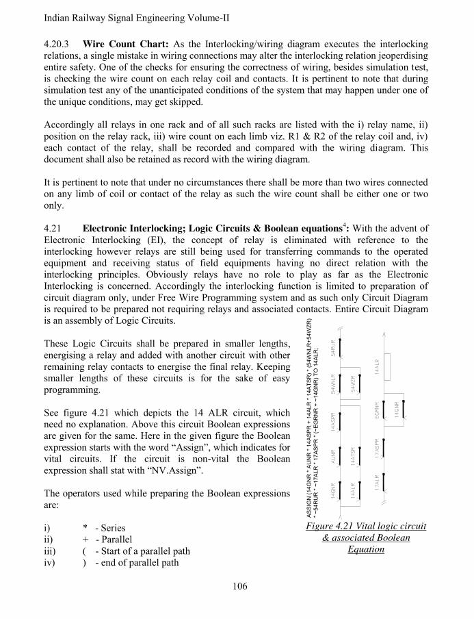
Indian Railway Signal Engineering Volume-II
106
4.20.3 Wire Count Chart: As the Interlocking/wiring diagram executes the interlocking relations, a single mistake in wiring connections may alter the interlocking relation jeoperdising entire safety. One of the checks for ensuring the correctness of wiring, besides simulation test, is checking the wire count on each relay coil and contacts. It is pertinent to note that during simulation test any of the unanticipated conditions of the system that may happen under one of the unique conditions, may get skipped. Accordingly all relays in one rack and of all such racks are listed with the i) relay name, ii) position on the relay rack, iii) wire count on each limb viz. R1 & R2 of the relay coil and, iv) each contact of the relay, shall be recorded and compared with the wiring diagram. This document shall also be retained as record with the wiring diagram. It is pertinent to note that under no circumstances there shall be more than two wires connected on any limb of coil or contact of the relay as such the wire count shall be either one or two only. 4.21 Electronic Interlocking; Logic Circuits & Boolean equations
4: With the advent of
Electronic Interlocking (EI), the concept of relay is eliminated with reference to the interlocking however relays are still being used for transferring commands to the operated equipment and receiving status of field equipments having no direct relation with the interlocking principles. Obviously relays have no role to play as far as the Electronic Interlocking is concerned. Accordingly the interlocking function is limited to preparation of circuit diagram only, under Free Wire Programming system and as such only Circuit Diagram is required to be prepared not requiring relays and associated contacts. Entire Circuit Diagram is an assembly of Logic Circuits. These Logic Circuits shall be prepared in smaller lengths, energising a relay and added with another circuit with other remaining relay contacts to energise the final relay. Keeping smaller lengths of these circuits is for the sake of easy programming. See figure 4.21 which depicts the 14 ALR circuit, which need no explanation. Above this circuit Boolean expressions are given for the same. Here in the given figure the Boolean expression starts with the word “Assign”, which indicates for vital circuits. If the circuit is non-vital the Boolean expression shall stat with “NV.Assign”. The operators used while preparing the Boolean expressions are: i) * - Series ii) + - Parallel iii) ( - Start of a parallel path iv) ) - end of parallel path
AS
SIG
N (
14G
NR
* A
UN
R *
14A
SP
R +
14A
LR
* 1
4A
TS
R)
* (5
4W
NLR
+54W
ZR
)
* ~
54R
UR
* ~
17A
LR
* 1
7A
SP
R *
(~
EG
RN
R +
~14G
NR
) T
O 1
4A
LR
;
Figure 4.21 Vital logic circuit
& associated Boolean
Equation

107 Pramod P. Goel
v) ~ - Back contact (there is no symbol for pickup contact) vi) , - Bit separation, vii) ; - End of statement/section viii) // - Single line comments ix) % - Multi line comments ......................Type 1 \ x) /* - Multi line comments .....................type 1 */ As the Circuit Diagram is finalised, each Logic Circuit is converted into Boolean Equation4
which in turn is used to prepare programme to be loaded onto the EI system. These equations are placed just above the corresponding Logic circuit for the benefit of being used for programming.
4.22 Interface Circuits, Bit Chart and preparation: While the Logic Circuits are used for the purpose of making the programme to be loaded onto the CPU of the EI, the interface circuits are to interconnect the processor through interface cards (I/O cards) and the relays to take the commands for operation of points and signals etcetera and to bring the status of points and signals etcetera from the field to the processor through interface cards. 4.22.1 Interface Circuits: The commands generated by the Control cum Indication Panel or by the VDU using the mouse, fed to the CPU through input/output card, are analysed with reference to the interlocking relations, status of the points, track vacancy, signals, level crossing gates etcetera, from the yard. The system executes the commands if found feasible, for i) receipt of the status from the yard and the ii) commands given by the Control cum indication Panel/VDU with a mouse. Relays are used to interface between the relay rack and the CPU both through input/output cards. A circuit is prepared for such interaction between the CPU and the relays. Such circuits prepared to interface between all inputs & out puts from and to, to the CPU are termed as Interface Circuits. See interface circuits for input status and output commands generated by the system [figure 4.22.1.1(I) & 4.22.1.1(II)].
4.22.1.1 Preparation of Interface circuits: Two groups of relays shall be mounted on the relay rack, one being energised by the field, bringing in the status of track circuits, point setting status i.e 55NWKR and signal lamps 18GECR etcetera [figure 4.22.1.1(i)] and the other being commands generated by the system for controlling and operating points viz. 55NWR or 55RWR, and signals such as 18GR [figure 4.22.1.1(ii)] and any other functions such as crank handles and Level crossing gates. Designer shall prepare Interface Circuit depicting connections between the port on the I/O card and the relays mounted on the relay rack at positions so defined. While the commands generated by the system cause the concerned relay to energise by extending power through the I/O card if the VOR relay is energised, the pickup/de-energised status of the relays is transferred to the system through I/O cards is, using Opto-couplers to avoid connecting power directly from the field. The free wire system of EI is provided largely in country by M/s Union Switch & Signals, the product having been named as Microlock. The circuits and layouts shall be put in groups as detailed in ensuing paragraphs:

Indian Railway Signal Engineering Volume-II
108
Figure 4.22.1.1(i) Interface circuit for
input to the system
Figure 4.22.1.1(ii) Interface circuit for
commands generated by the system
4.22.2 Bit Chart: The Bit is the position on which a relay with its name is fixed, addressed by the CPU as programmed. Bits are vital, being related directly to the safety and non-vital being commands, indications and other non vital functions. Accordingly a Vital Bit chart is
prepared as an integral part of the interface circuits on which the position of relays bringing in the status of the field equipment such as that of the signals and points etcetera and issuing commands to energise relays to operate point and signal, is tabulated as 4.22.2.
SHEET NO.
162 & 163
164 & 165
166 & 167
168 & 169
188 & 189
190 & 191
192 & 193
194 & 195
196 & 197
198 & 199
POSIT-ION
SLOT 1
SLOT 2
SLOT 3
SLOT 4
SLOT 5
SLOT 6
SLOT 7
SLOT 8
SLOT 9
SLOT 10
TERM-INAL NO.
R1B1 R1B2 R1B3 R1B4 R1B5 R1B6 R1B7 R1B8 R1B9 R1B10
TYPE BIT NO.
VITAL *O/PUT
VITAL *O/PUT
VITAL *O/PUT
VITAL *O/PUT
VITAL INPUT
VITAL INPUT
VITAL INPUT
VITAL INPUT
VITAL INPUT
VITAL INPUT
BIT 1 1DR C75GR 207 NWCR
SPARE
10 ECR
C75 GECR
S14 DECPR
SPARE 75 ATPR
5A MGCR
BIT 2 1HHR 75DR 207 RWCR
1A MGR
1 HHECR
75 DECR
S14HHECPR
SPARE 75 BTPR
5AG MGECR
BIT 3 1HR 75 HHR 295 NWCR
71A MGR
1 HECR
75 HHECR
S14 HECPR
CH201 NPR
C71 TPR
201 NWCPR
BIT 14 207 WCR
201 RWCR
201 WCR
SPARE 71 HECR
171 GECR
295 RWKRF
75 TPR 5A TPR
1A MGECR
BIT 15 295 WCR
205 NWCR
SPARE SPARE 71 RECR
SYS DIG
299 NWKRF
299A TPR
1 TPR 75A MGECR
BIT 16 299 WCR
205 RWCR
205 WCR
SPARE 71 UGECR
SYS NORMAL
299 RWKRF
299B TPR
S14 TPR
SPARE
Table 4.22.2 Vital Bit Chart

109 Pramod P. Goel
The first row of the table depicting sheet number columns show the number of the sheet on which the circuit for the concerned input or output relay is placed. Second row of the table shows the slot position. Third row shows the terminal number through which the concerned relay is connected. Fourth row of the table depicts type of Bit, i.e. input or output. The extreme left column of the table depicts the position of the Bits. As there are 16 bits for each slot, each position of the relay is identified with respect to the cross section of the Bit and the Slot number. First and last three bits have been shown in this table considered enough to establish the principle and also to save space as the designer shall prepare Bit Chart for all the sixteen bits. *Read O/Put in the table as Out Put. 4.22.4 Room floor plan for EI equipment and power supply: Room floor plan shall be designed based upon the area on which the system has to be installed.
However System configuration shall be prepared depicting all connections between Processing units based on architecture of one out of one or two out of two or two out of three used, between system & system, System and i) Operator PC, ii) Data logger, iii) Maintenance terminal, iv) Relay racks, and between relay rack and the cable termination (CT) rack are depicted. See figure 4.22.4(i) & 422.4 (ii) respectively.
MAINTAINNER'S CABIN
RA
CK
R-1
RA
CK
R-2
RA
CK
R-3
RA
CK
R-4
RE
LA
Y R
AC
KS
CT RACK 1 CT RACK 2 CT RACK 3 CT RACK 4
EI SYSTEM
RACKS
EI SYSTEM
RACKS
EI SYSTEM
RACKS
WINDOW WINDOW
IPS
WIN
DO
WW
IND
OW
BATTERY ROOM
DOOR
EQUIPMENT (IPS)ROOM
Figure 4.22.4(i) Room floor plan for E.I. Figure 4.22.4(ii) Room floor plan for
power supply

Indian Railway Signal Engineering Volume-II
110
4.22.5 System Rack Layout: Two type of System Rack Layouts are required, A) bearing the i) VCO Relay (VCOR), ii) System card files etcetera and, B) having, i) Power supply system with Fuses, and Negative terminals on its upper section and ii) relays of QNN series, on its lower section. This diagram is akin to the Composite Relay Rack chart, as prepared in case of electrical interlocking. There may be more than one rack depending upon multiplicity of configuration of system scheduled to be used such as, two out of two or two out of three. It is pertinent to note that vital bit chart has to be in consonance to this relay rack chart. 4.22.6 System configuration plan: The system configuration as shown in the figure 4.22.6 is for Two out of two, based on Microlock design. Accordingly systems ‘A’ and ‘B’ are connected with each other not shown in this diagram, using two operating systems connected to Relay rack charts, the Data Logger, Maintenance PC and cable termination racks. The diagram is placed for conceptual understanding and it does not cover all details here which are discussed in different paragraphs. 4.22.7 Card file layout: Microlock uses twenty slots to accommodate I/O Cards, 16th and 17th slots being used for power supply and 18th and 19th slots for the CPU; 20th position being usually kept reserved as spare [figure 4.22.7(i)]. Since each I/O card is specific to its position on the rack, a keying plug location is
defined for each such card so as to ensure that no other card can be put in a position other than meant for the specific card. The arrangement is similar to the indexing in case of ‘Q’ series relays to select its position with reference to the contact configuration viz. 12F-4b, 8F-8b and so on. A 12 Slot Keying Plug Female Connector is placed adjacent to the 48/96 female connector on the Card File Mother Board, six of the twelve slots are plugged so arranged as to ensure that only the given card file is able to be inserted into the female connector; See figure 4.22.7 (ii) for keying arrangements for card
files and & table 4.22.7, (iii) for Card file keying plug locations forming keying plug codes.
Figure 4.22.7(ii) Keying
arrangement for card files

111 Pramod P. Goel
SS
SS
S
SS
M
M
MM
M
MM
M
M
M
M M
M
SYSTEM A/B SELECTION
CIRCUITS
TO/FROM YRAD
C.T. RACKS
RELAY RACK 3RELAY RACK 2RELAY RACK 1
I1
MAINTENANCE PC &
DIAGNOSTIC
D-CONNECTOR BOX
MAINTENANCE
PC
S
M
DATA LOGGER
D
P2 P1
P5
P4P3
P5 D
P1P2
P4P3
D-
CONNECTOR
BOX
MICROLOCK
B
MICROLOCK
A
OPERATOR PC 2
S
OPERATOR PC 1
Figure 4.22.6 System configuration plan
Figure 4.22.7(i) Card Fie Layout

Indian Railway Signal Engineering Volume-II
112
Printed card board Keying plug locations
1 2 3 4 5 6 7 8 9 10 11 12
CPU ● ● ● ● ● ●
Power supply (without panel) ● ● ● ● ● ●
Power supply (with panel) ● ● ● ● ● ●
Standard Vital output(12V) ● ● ● ● ●
Standard Vital output(24V) ● ● ● ● ● ●
Non vital bi-polar output ● ● ● ● ● ●
Vital lamp driver ● ● ● ● ● ●
Vital input (12V) ● ● ● ● ● ●
Vital output (24V) ● ● ● ● ● ●
Vital input (50V) ● ● ● ● ● ●
Mixed Vital I/O (12V) ● ● ● ● ● ●
Mixed Vital I/O (24V) ● ● ● ● ● ●
Mixed Vital I/O (50V) ● ● ● ● ● ●
Serial Link Relay PCB ● ● ● ● ● ●
Code system interface ● ● ● ● ● ●
Non vital I/O N17000601 ● ● ● ● ● ●
Non vital I/O N17061501 ● ● ● ● ● ●
Non vital isolated N17002801 ● ● ● ● ● ●
Non vital isolated N17062701 ● ● ● ● ● ●
Non vital isolated N17063701 ● ● ● ● ● ●
Coded Track Circuit N451910-0701 ● ● ● ● ● ●
Coded Track Circuit N451910-7601 ● ● ● ● ● ●
Coded Track Circuit N451910-7602 ● ● ● ● ● ●
Coded Track Circuit N451910-7603 ● ● ● ● ● ●
OS Track circuit ● ● ● ● ● ●
Coder output ● ● ● ● ● ●
Auxiliary coder output ● ● ● ● ● ●
60/100 Hz cab amplifier ● ● ● ● ● ●
40/50 Hz cab amplifier ● ● ● ● ● ●
CPS only power supply-no front panel
No keying plugs provided
CPS only power supply-with front panel
No keying plugs provided
Table 4.22.7(iii) Card file keying plug locations
4.22.8 I/O Jumper settings & Address circuits: As the command is generated by CPU to energise a relay, say 3HR, it is required to be addressed to the said relay for this purpose an address select PCB is mounted on the hood of each card file to route the command for the selected relay to be energised.

113 Pramod P. Goel
Each addresses select PCB mounted onto the PCB card file is jumper specific. A typical, such jumper connections/settings of address select PCBs for slot-1 to slot-5 specific for card files in these slots on the rack, are placed as figure 4.22.8(i). Remaining Address select PCBs between 6 & 15 for corresponding slots shall also be configured on pattern given as shown in figure number 4.22.8(ii) on page number 114. It is pertinent to note that for connecting the addressed circuits to the Board, the power SEL+ is connected with Jumper coloured white through pin E32 on the PCB and on the Address select PCB terminal numbered ‘1’ (one), all looped together. The Ground (GND) connected with Jumper coloured black to the Board pin A26 at the PCB and to the ‘(0)’ (zero) numbered terminals, all looped together on the Address select PCB. Other jumpers are connected to the pin A28 coloured blue, pin C28 green, pin E38 yellow, pin A30 orange, pin C30 red and pin E30 brown at the vital input PCB. These wires are connected to Address Select PCB depending upon the configuration of the PCB on which the address select PCB is mounted. See figure 4.22.8(iii) for Jumper settings of the Address select PCBs. 4.22.9 CPU, EEPROM & Power Supply connections: The CPU is designed for five serial ports connected through a serial isolator unit. Selection and configuration of serial ports is controlled and managed by the Application
Figure 4.22.8(i) Jumper settings of Address select PCBs slots 1 to 5
Figure 4.22.8 (iii) Jumper settings of Address select
PCBs

Indian Railway Signal Engineering Volume-II
114
software. [Figure 4.22.9] Part CPU is depicted connected to PCB EEPROM through jumpers as well as to power supply Board.
Figure 4.22.9 CPU, EEPROM & Power Supply connections
Figure 4.22.8(ii) Jumper settings of Address select PCBs slots 6 to 15
The EEPROM PCB is mounted on the hood of the CPU. CPU terminals C30, E32, E20, E32, C32, C28 & E28 are connected to the PCB EEPROM, through jumpers J1 to J6 respectively. CPU terminal E20 is also connected to its port-2. The power supply board (PSB) positioned in slot 16-17, is also depicted in part, extending

115 Pramod P. Goel
power to the CPU at E28. 12 V DC power is connected to the PSB. It also energises VCOR. This relay playas a major role in ensuring system’s health and all functions between I/O cards and shall take place only when this relay is energised. 4.22.10 CPU board jumper settings: The circuit depicts part of the CPU board connected to the EEPROM and also to the part power supply board shown in the diagram connected to which the VCOR is energised. See figure 4.22.10.
NOT INSTALLED
POSITION 1-2
POSITION 2-3
OFF
LOUD
SOFTSPEAKER VOLUMEJMP25
PROGRAM
LOCKED
(BOOT SPACE)
FLASH 1 BOOT BLOCK
PROGRAM
LOCKEDFLASH 4 PROGRAMMING LANGUAGE
(APPLICATION SPACE)
PROGRAM
LOCKED
(EXECUTIVE SPACE)
FLASH 2 PROGRAMMING LANGUAGE
(EXECUTIVE SPACE) PROGRAM
LOCKEDFLASH 1 PROGRAMMING LANGUAGE
(APPLICATION SPACE)
RS-423
RS-232
CPU PCB JUMPER POSITIONS
RS-423
RS-232
JMP6
#2
POSITION 2-3
POSITION 1-2JMP24
#2
POSITION 2-3
POSITION 1-2JMP23
#2
POSITION 2-3
POSITION 1-2JMP22
#2
POSITION 2-3
POSITION 1-2JMP21
#2POSITION 2-3
POSITION 1-2
PROGRAM
LOCKEDFLASH 3 PROGRAMMING LANGUAGE JMP20
NOT APPLICABLE
NOT AVAILABLEJMP19
POSITION 1-2JMP18 COM1 RX.CLK=9.83mhz
POSITION 1-2COM2 RX.CLK=9.83mhzJMP17
POSITION 1-2COM3 RX.CLK=9.83mhzJMP16
POSITION 1-2COM4 RX.CLK=9.83mhzJMP15
POSITION 1-2COM3 TX.CLE IS AN OUT PUTJMP14
POSITION 2-3COM3 TX.CLE IS AN OUT PUTJMP13
POSITION 1-2
POSITION 2-3
COM3 VOLTAGE DRIVE LEVELSJMP12
POSITION 2-3
POSITION 1-2COM3 VOLTAGE DRIVE LEVEL JMP11
POSITION 2-3COM1 TX.CLE IS AN OUT PUTJMP10
POSITION 1-2DISABLE BACKPLANE CPU RESETJMP9
POSITION 1-2ENABLE COM4 DCDJMP8
POSITION 1-2ENABLE COM4 RXDJMP7
#1POSITION 2-3FLASH 1 WAIT STATE
NOT INSTALLEDJMP5
POSITION 2-3TOP PCMCIA 2 WAIT STATESJMP4
#1POSITION 2-3NO-BOARD RAM 1 WAIT STATESJMP3
NOT INSTALLEDJMP2
POSITION 2-3JMP1 BOTTOM PCMCIA 2 WAIT STATES
NOTESPOSITIONDESCRIPTIONJUMPER ID
DISABLE
ENABLE
ENABLE
DISABLE
COMM 5
COMM 4
PROGRAM
LOCKED
PROGRAM
LOCKED
MICROL OK II CPU PCB JUMPER POSITIONS
JUMPER ID
POSITION 2-3
POSITION 1-2JMP 36 BACKPLANE SYS.CLK
ENABLE
DISABLE
JMP 35
POSITION 2-3
POSITION 1-2RTC COIN BATTERY ENABLE
POSITION 2-3
POSITION 1-2JMP 34 EXTERNAL"5VBAT"ZENER DIODESELECT(REGULATES TO 3.3V)
POSITION 2-3
POSITION 1-2JMP 33 JI COMM PORT 4 TX SELECT
POSITION 2-3COMM 5
COMM 4 POSITION 1-2JI COMM PORT 4 TX SELECTJMP 32
#1POSITION 1-2CPS DRIVE NORMALJMP 31
#2
POSITION 3-4
POSITION 2-3
POSITION 1-2FLASH PROGRAMMING VOLTAGE
12V
5V
OFFJMP30
#2
POSITION 2-3
POSITION 1-2BOTTOM PCMCIA PROGRAMMING VOLTAGEJMP29
#2
POSITION 2-3
POSITION 1-2TOP PCMCIA PROGRAMMING VOLTAGEJMP28
#1POSITION 1-468332 NORMALJMP27
POSITION 2-4JMP26 IRQ7 OFF
DESCRIPTION POSITION NOTES
Figure 4.22.10 CPU board jumper settings

Indian Railway Signal Engineering Volume-II
116
4.22.11 Serial Communication circuits: The CPU has five serial ports to communicate with peripheral devices through serial communication as per Microlock design. Ports 1 & 2 interface with vital control systems, port 3 interface with non-vital control systems such as operator’s PC, port 4 interfaces with other non-vital control systems such as Control cum Indication panel and port ‘5’ is to interface with Maintenance PC. See figure 4.22.11 for Master-Slave serial CPU Port
Communication Circuits. 4.22.12 Maintenance Personal Computer
Diagnostic Serial Communication circuits: Maintenance PC connected with the CPU through 9 pin D-connector in D-connector box, is mounted over the maintenance computer table, there from is connected to the CPU board front panel diagnostic serial port number 5. The Maintenance Personal Computer (PC) is connected to the D-9 pin connector which is placed in the box. The said box is mounted on the maintainer’s computer table. There from the box, connection is taken to diagnostic port of the CPU using 9 pin D-connector in between. More connections are derived for other systems. See figure 4.22.12.
Figure 4.22.12 Maintenance Personal Computer diagnostic serial communication circuits
A22
#22
#20#21
A16
A26
#20 #20
#20#20
#20#20
RTS-
RTS+
TXD-
TXD+
RXD-
RXD+
DCD-
DCD+
A20
A22
A16
A18
A24
A28
0V
A30
A32
GREEN
WHITE
1
BROWN
CONTINUED
BLACK
#22
PART OF CPU BOARDSLOT 18 & 19PORT-2 MASTER
DCD-
DCD+
RXD-
RXD+
TXD-
TXD+
RTS-
RTS+
A28
A30
A24
A26
A16
A18
A20
PART OF CPU BOARDSLOT 18&19PORT-2SLAVE
Figure 4.22.11 Master- Slave CPU board
Serial communication circuits

117 Pramod P. Goel
4.22.13 Data logger Serial Communication circuits: Data logger is connected to the CPU as well as to the Maintenance Diagnostic Personal Computer. The circuit between the Data logger and the CPU may be seen as figure number 4.22.13.
4.22.14 CPU Clock Supply circuits: Time element relays and other checking devices are run by CPU clock. The circuit controlled by 12V DC/5 V DC, DC-DC converter to supply power for such clockworks is provided at figure 4.22.14.
PCB MODULAR CLAMP TERMINAL
A3 CARD FILE
A2 CARD FILE
A1 CARD FILE
+5V
+5V BATT
GND
-12V
+12VPWF
+5V
GND
GND
+5V
PWF+12V
-12V
GND
+5V BATT
+5V
+5V
+5V BATT
GND
-12V
+12VPWF
+5V
GND
B SYS ON
B SYS ON
5V DC-DCCONVERTER
B 12
N 12
Figure 4.22.14 CPU Clock Supply circuits
TO OTHER CPU
N 12
B 12
12V DC
ISOLATOR
BLACK
YELLOW
GREEN
RED
BLUE
A16
PART OF CPU BOARDSLOT 18 &19M, PORT-4,
SLAVE
9 PIND-CONNECTOR
DATALOGGER MASTER
BLACK
GREEN
YELLOW
BLUE
RED
BLACK
YELLOW
GREEN
RED
BLUE
COM
RTS
DCD
TXD
RXD
5
7
1
3
2
COM
RTS
DCD
TXD
RXD
5
7
1
3
COM
DCD
RTS
RXD
TXD
2
E22
C16
A14
C22
C20
COM
RTS
DCD
TXD
RXD
Figure 4.22.13 Data logger Serial Communication circuits
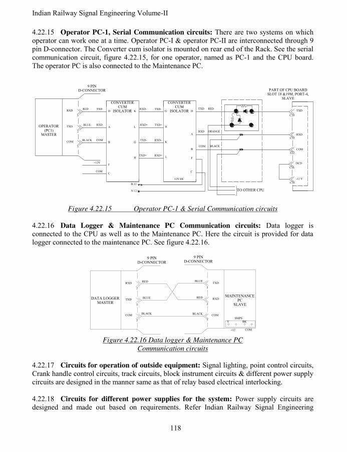
Indian Railway Signal Engineering Volume-II
118
4.22.15 Operator PC-1, Serial Communication circuits: There are two systems on which operator can work one at a time. Operator PC-I & operator PC-II are interconnected through 9 pin D-connector. The Converter cum isolator is mounted on rear end of the Rack. See the serial communication circuit, figure 4.22.15, for one operator, named as PC-1 and the CPU board. The operator PC is also connected to the Maintenance PC.
TO OTHER CPU
-12 V
C26
DCD
C16
COM
E22
BLACKCOM
ORANGERXD
C
L
K
H
G
TXD-
RXD+TXD+
RXD-
TXD+RXD+
TXD-RXD-
12V DC
CONVERTERCUM
ISOLATOR D
A
B
FH
G
L
K
COM
+12V
C
F
B
A
D
5
2
RXD
TXD
COM
C20
C22
TXD
RXD
RXD
TXD
COM
3
TXD RED
OPERATOR(PC1)
MASTER
9 PIND-CONNECTOR PART OF CPU BOARD
SLOT 18 &19M, PORT-4,SLAVE
BLUE
RED
BLACK
CONVERTERCUM
ISOLATOR
B 12
N 12
Figure 4.22.15 Operator PC-1 & Serial Communication circuits 4.22.16 Data Logger & Maintenance PC Communication circuits: Data logger is connected to the CPU as well as to the Maintenance PC. Here the circuit is provided for data logger connected to the maintenance PC. See figure 4.22.16.
COM+12
SMPSBKY
COMBLACK
RXD
BLUETXD
RED
5
2
3
MAINTENANCEPC
SLAVE
9 PIND-CONNECTOR
9 PIND-CONNECTOR
BLACK
RED
BLUEDATA LOGGER MASTER
2
COM
TXD
RXD
3
5
Figure 4.22.16 Data logger & Maintenance PC
Communication circuits
4.22.17 Circuits for operation of outside equipment: Signal lighting, point control circuits, Crank handle control circuits, track circuits, block instrument circuits & different power supply circuits are designed in the manner same as that of relay based electrical interlocking. 4.22.18 Circuits for different power supplies for the system: Power supply circuits are designed and made out based on requirements. Refer Indian Railway Signal Engineering

119 Pramod P. Goel
Volume –IV for details by the author same as that of this book. 4.22.19 Rack Termination Chart: Similar to the arrangement made in case of electrical interlocking achieved through relays, the all cable conductors leading out from the system and leading in from the field are terminated on a rack onto which double deck Phoenix type terminals are used. These terminals requiring space much smaller as compared to the ARA terminals are used on cathode with disconnecting facility and diode indication while the single deck Phoenix non-disconnecting type terminals are used for anode. See the sample rack terminal chart at figure 4.22.19.
162162162162162162162
CA
BL
EN
24
299WCR295WCR
C71GR
163163163163163163163163
32313029282726252423222120191817
71HR
5HR7HRSPARE
71DR71HHR
1DR 1621HHR1HR5DR5HHR
71U1GR207WCR
163299WCR416316
116
163295WCR415315
115
163
163
163
163
163
207WCR414314
114
162
162
71U1GR413313
113
71HR412312
112
71HHR411311
111
71DR410310
110
163C71GR409309
109
162SPARE408308
108
1627HR407307
107
1625HR406306
106
5HHR405305
105
162
5DR404304
104
162
1HR403303
103
1HHR402302
102401
1621DR301101
SHEETFUNCTION
R1B1 VITAL OUTPT
R0W
Figure 4.22.19 Rack terminal chart
4.22.20 Contact analysis: with the introduction of the electronic Interlocking the format of the Contact Analysis used is different as compared to the format used under system of electrical interlocking. See the sample format for contact analysis at figure number 4.22.20.

Indian Railway Signal Engineering Volume-II
120
RE
LA
Y
1D
R1
1D
R
RE
LA
Y
TIT
LE
TIT
LE
TY
PE
CONTACTS
POSITION
QN
N1
2X
6F
-2B
R1F
1
R1
R3
R2
R4
WS
HW
CO
ILS
WS
HW
A1
A2
A3
A4
WS
HW
WS
HW
CO
NT
AC
TS
A5
A6
A7
A8
B1
B2
B3
B4
WS
HW
WS
HW
WS
HW
WS
HW
B5
B6
B7
B8
WS
HW
WS
HW
WS
HW
WS
HW
D8
D7
D6
D5
WS
HW
WS
HW
WS
HW
WS
HW
D4
D3
D2
D1
C8
C7
C6
C5
WS
HW
WS
H
C4
C3
C2
C1
W
21
62
2
11
51
1
25
11
21
25
11
12
51
11
25
12
12
51
11
25
11
12
51
11
DR
1D
R1
12
51
12
51
11
BA
FA
FA
AB
AF
FA
F A
A B
F A
A BB
AB
A
AF
FA
AF
AF
BA
AF
AF
AB
1H
HR
1H
R
QN
N1
2X
6F
-2B
R1F
22
16
22
22
26
2
1H
HR
1H
R1
15
11
11
51
11
15
11
11
51
11
15
11
5D
R
5D
R1
QN
N1
2X
6F
-2B
R1F
32
16
22
12
52
1
5D
R
5D
R1
12
52
11
25
21
12
52
12
52
12
11
25
22
52
11
12
52
2
12
52
11
25
21
71H
R
71U
1G
R
QN
N1
2X
6F
-2B
R1F
8
1A
MG
R
71A
MG
R
QN
N1
2X
6F
-2B
R1F
9
21
63
2
21
63
271H
R
71U
1G
R1
25
41
11
25
41
12
54
11
25
41
12
54
12
54
11
25
41
12
54
11
25
41
1A
MG
R
71A
MG
R1
68
22
21
68
21
25
11
12
51
11
25
11
12
51
1
12
54
11
25
41
12
54
11
25
41
Fig
ure
4.2
2.2
0
Conta
ct a
naly
sis
for
E.I
.

121 Pramod P. Goel
4.23 Test Records: Important test records of track circuit maintenance, Cable Core Insulation, Earth leak detector for incidences of leakage due to low insulation, are maintained on the format specified by the SEM Part-I, 1988. 4.23.1 Track Circuit Test card: As a track circuit, which may be DC track circuit, AC track circuit, Jeomont tack circuit, AFTC, coded track circuit etcetera, is invariably superimposed on the pair of rails, the efficacy of the track circuit depends upon ‘Train Shunt Resistance’ (TSR). Accordingly the TSR should be checked and recorded frequently on the Track Circuit Test Record Card, to maintain safety. The card shall have details as provided in SEM- September- 2001, paragraph 17.32.1. See the format as Appendix-X for DC track circuits, Card Number S&T/TC-1; Appendix-XI for AC Track circuits, Card number S&T/TC-2 and Appendix-XII, for Jeumont type track circuits, Card number S&T/TC-3. 4.23.2 Cable core insulation chart: When the cable is the medium of communication between the operating unit and operated equipment, the integrity of the cable conductor insulation is of vital importance. As in case on damaged insulation between two conductors within any one cable may result in energising the relay responsible for lighting the signal directly without ensuring interlocking relation established. This is the reason for which the insulation between each conductor and all other conductors are essentially required to be tested at 500 Volts, yearly. Procedure of testing shall be i) disconnect all cores of the cable at both ends, ii) connect one Probe of the Cable Insulation Tester to first core of the cable to be tested, connect all remaining conductors together and connect the other Probe to the bunch of all such conductors, iii) test all balance conductors one by one against the bunch of all remaining conductors, iv) record the insulation reading of the Cable Insulation Tester, on a register meant for the purpose for each conductor of each cable. Insulation resistance should not be allowed to continue if any conductor of the cable is found to be below 5 mega ohms. Refer paragraph 15.23 of SEM Part-I, September-2001. See format for cable core insulation test record as Appendix XIII. 4.23.3 Earth Leakage Detector: Owing to cable testing being done periodically as well as often during high moist atmosphere the insulation between the cable conductors getting low continuously is always better to monitor each cable on line. This is being done by using Earth Leakage Detector. The spare conductors in the cable are connected with one terminal of the Earth Leakage Detector while other terminal is earthed. As the insulation of the conductors falls below 500 mega ohm the current shall flow through the low insulation cable conductor to earth there by energising the audio and video indications, necessitating immediate testing of the cable concerned an taking remedial measures. 4.23.4 Equipment Disposition and Power Supply Allocation plan: Equipment Disposition plan and Power Supply plan are required to be designed taking into consideration of i) maximum utilisation of the minimum space, ii) use of minimum length of conductors for the sake of minimum loss of power across conductor as well as economy of cost and copper, iii) to meet with the compulsion of keeping minimum distance between source of power supply and
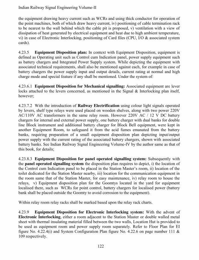
Indian Railway Signal Engineering Volume-II
122
the equipment drawing heavy current such as WCRs and using thick conductor for operation of the point machines, both of which draw heavy current, iv) positioning of cable termination rack to be nearest to the wall behind which the cable pit is proposed, v) ventilation with a view of dissipation of heat generated by electrical equipment and heat due to high ambient temperature, vi) in case of Electronic Interlocking, positioning of Card files (CPU, I/O & associated system cards). 4.23.5 Equipment Disposition plan: In context with Equipment Disposition, equipment is defined as Operating unit such as Control cum Indication panel, power supply equipment such as battery chargers and Integrated Power Supply system. While depicting the equipment with associated technical requirements, shall also be mentioned against each, for example in case of battery chargers the power supply input and output details, current rating at normal and high charge mode and special feature if any shall be mentioned. Under the system of: 4.23.6.1 Equipment Disposition for Mechanical signalling: Associated equipment are lever locks attached to the levers concerned, as mentioned in the Signal & Interlocking plan itself, however; 4.23.7.2 With the introduction of Railway Electrification using colour light signals operated by levers, shelf type relays were used placed on wooden shelves, along with two power 220V AC/110V AC transformers in the same relay room. However 220V AC / 12 V DC battery chargers for internal and external power supply, one battery charger with dual banks for double line Block instrument and additional battery charger for Block Bell equipment, were kept in another Equipment Room, to safeguard it from the acid fumes emanated from the battery banks, requiring preparation of a small equipment disposition plan depicting input/output power supply with the current rating of the associated battery chargers, shown with associated battery banks. See Indian Railway Signal Engineering Volume-IV by the author same as that of this book, for details; 4.23.8.3 Equipment Disposition for panel operated signalling system: Subsequently with the panel operated signalling system the disposition plan requires to depict, i) the location of the Control cum Indication panel to be placed in the Station Master’s room, ii) location of the toilet dedicated for the Station Master nearby, iii) location for the communication equipment in the room same that of the Station Master, for easy maintenance, iv) relay room to house the relays, v) Equipment disposition plan for the Goomtys located in the yard for equipment localised there, such as WCRs for point control, battery chargers for localised power (battery bank shall be placed outside the Goomty to avoid corrosion to the equipment). Within relay room relay racks shall be marked based upon the relay rack charts. 4.23.9 Equipment Disposition for Electronic Interlocking system: With the advent of Electronic Interlocking, either a room adjacent to the Station Master or double walled metal sheet with thermal insulating material filled between the two walls, Location Hut is provided to be used as equipment room and power supply room separately. Refer to Floor Plan for EI figure No. 4.22.4(i) and System Configuration Plan figure No. 4.22.6 on page number 111 & 109 respectively.

123 Pramod P. Goel
4.23.10 Power supply allocation plan: Associated to each power supply equipment/battery charger as discussed under the preceding paragraph of Equipment Disposition Plan, corresponding battery bank or other source of power supply shall be given. See volume IV of Indan Railway Signal Engineering Chapter VIII paragraph number 4.
Figure 4.23.10.1 Power supply disposition plan for IPS

Indian Railway Signal Engineering Volume-II
124
4.23.10.1 Power supply allocation for Integrated Power Supply system: As concurrently Integrated Power Supply (IPS) system has taken over the old scattered power supply system by unified system with single battery bank as against multiple battery banks, it has made the equipment disposition very simple. Also refer to the chapter on power supply in the book Indian Railway Signal Engineering Volume-IV by the author same as that of this book, for power supply allocation provided with IPS and further details. See power supply disposition plan with IPS at figure number 4.23.10.1. 4.23.10.2 Power supply allocation for Solar Power system
4: Many stations where power
supply from state electricity board is not available Solar Power Supply system is used to run the Multiple Aspect Colour Light Signalling operated by Control cum Indication Panel. The panel is designed by permutations and combinations of solar cells arranged in series to achieve desired voltage and arranged parallel to achieve the desired capacity of the power supply. Each Silicon solar cell when exposed to sunlight, photons generates 100ma at 0.45 Volts which works out to be 45 milli watts DC from each cell measuring 6.45 sq cm (2 inches x 0.5 inches). The 2.2 V lead acid cell, each of the desired capacity to form bank accordingly shall be procured connected in series to form the power supply voltage as required. That capacity of each such cell shall be based on time for which the system requires to be sustained. Also refer Chapter on power supply of Indian Railway Signal Engineering Volume-IV, by the author same as that by this book, for more information.
*****

125
APPENDIX- I Section 20 of Indian Railway Act reads as “Power of Central Government to give directions for safety- Notwithstanding anything contained in any other law, the Central Government may, if it is of the opinion that any work undertaken or may be undertaken, is likely to alter or impede the natural course of water flow or cause an increase in the volume of such flow endangering any cutting, embankment or other work on a railway, issue directions in writing to any person, officer or authority responsible for such work to close, regulate or prohibit that work”.
*****

126
APPENDIX-II
Application to CRS for sanction to execute the work
.................Railway Office..................... Department........... Dated....................... No......................... From: The....................... Designation.......... To, The Commissioner of Railway Safety, ............................................................. Sir, 1. I hereby apply for your sanction to*............................................................................................................... ............................................................................................................................. .............................................................. ............................................................................................................................. .............................................................. Being commenced and opened for public carriage of passengers when ready. 2. With reference to Chapter VI of the Rules for Opening of a railway, I have to enquire whether you wish to inspect the work prior to opening for public carriage of passengers, in which case intimation will be given of the date of completion. 3. In the vent of your deciding not to inspect the work prior to opening, the Engineer-in-Charge will, on completion of the work, submit the Safety Certificate, duly signed by him, prior to the opening of the work for public carriage of passengers and when required, also despatch a telegram** to your address intimating that the work has been opened and the Safety Certificate has been signed by him. 4. The application for the use of locomotives and rolling stock to be drawn or propelled thereby on proposed line, in accordance with the section 16(1) of the Indian Railway Act, 1890 (IX of 1890), is sent herewith/not required. 5. The following documents@ are enclosed:
I. Temporary works:
a) Description of proposed works. b) Drawing of temporary works. c) List of infringement to Schedule of Dimensions. d) List of deviations from Signal Engineering Manual. e) List of deviations from General and Subsidiary Rules. f) Restrictions. g) Rules for traffic working. h) Documents for bridges as per Chapter VII of Rules for Opening of a Railway. II. Permanent Works:
a) Description of proposed works. b) Drawing of permanent works. c) List of infringement to Schedule of Dimensions. d) List of deviations from Signal Engineering Manual. e) List of deviations from General and Subsidiary Rules. f) Restrictions. g) Rules for traffic working. h) Documents for bridges as per Chapter VII of Rules for Opening of a Railway.

127
6. Certified that detailed examination of the strength and arrangement of the material to be used in the temporary/ permanent works in the above connection, have been made and that the design and materials to be used are up to the loads, which they will be required to carry and that their opening for public carriage of the passengers will not be attended with any danger. (Delete temporary or permanent work, as the case may be). Yours faithfully Signature....................................... Designation................................... Dated............................................. No...................................... From The Commissioner of Railway Safety, ............................................................... Sir, Your No................................................................................. Sanction is accorded to the above work being carried out. %I do not propose to to inspect the work prior to its opening for the carriage of passengers. When ready, it may be opened on a safety Certificate (vide paragraph 3 of your letter) which should be submitted to me direct without any delay. % I propose to inspect the work prior to its opening for the public carriage of passengers. Advice of the date, when work will be ready for inspection, should be intimated at least 14 days before it is proposed to open it. ................................................... Commissioner of Railway Safety * Here enter name of work and mention whether permanent or temporary. ** Form of telegram: “Reference sanction No ................................dated..........................work opened for public traffic on................................First train to pass.................................No danger to public. Cer tificate signed”. @ If any of the documents are not sent, then ‘NIL’ to be written against such items. Working rules for extensive remodelling scheme may be sent in not later than one month before the date on which the work is to be brought into use, and in such cases “will follow” should be written instead “NIL”. % Strike out paragraph not applicable.
*****

128
APPENDIX-III
Safety Certificate ........................................RAILWAY When the Commissioner of railway Safety, does not inspect the work prior to opening, this certificate must be signed before opening temporary or new works. From, The Divisional railway Manager/Deputy Chief Engineer/Deputy Chief Signal & Telecommunication Engineer (Construction)............................division To, The Commissioner of Railway Safety, ................................................................. Description of work ......................................................................................................... ................................................. ............................................................................................................................. .............................................................. Reference: Divisional Railway Manager/ Chief Engineer/ Deputy Chief Engineer (Construction), Deputy Chief Signal & Telecommunication Engineer (Construction). Application................................................................................................................ ....dated............................................ Sanctioned under Commissioner of Railway Safety No...........................................dated........................... .................to Commence and open the above work. Following permanent/Temporary work has been done: ............................................................................................................................. .............................................................. ............................................................................................................................................................... ............................ I/We do hereby certify that, in the work above mentioned-
(i) The Schedule of Dimensions has not been infringed* except in regard to the items sanctioned under letter No..........................................dated.......................
(ii) Engineering work has been carried out in accordance with the plan No............................*except in regard to the alterations sanctioned under letter No.........................................dated................................
(iii) The weight of rails, strength of bridges and general structural character of the work are such as have
been prescribed under the rules.
(iv) The *Signalling and *Interlocking and *Block Signalling has been carried out in accordance with Signalling Plan No............................and the requirements and instructions laid down in the signal engineering manual have been completed *except in regard to the items sanctioned under letter No.................................dated.............................
(v) The work has been carried out in accordance with the documents already supplied.
1. A certificate from Divisional Safety Officer/...................................stating that the necessary working
rules have been issued and giving reference in regard to sanction to deviation (if any) from General and Subsidiary Rules is attached/not required. *To be scored out if not applicable.

129
2. I/We hereby certify that on the .............................................................20......., I/We have carefully inspected and tested the above work and that I/We have satisfied myself/our self that it has been completed and is in good working order* and that the work can be opened for public carriage of passengers without endangering the safety of the travelling public, or of the employees subject to the following speed restrictions: @Temporary ..........................km p.h................................ .........due to ............................................................. ............................................................................................................................. .............................................. @Permanent............................km p.h........................................due to......................................... ..................... ............................................................................................................. .............................................................
3. The work is being opened on ...................................................................... *Necessary in case of signalling and Interlocking works only. @To be scored out if not applicable.
Countersigned by:
............................................................ .................................................... Assistant Engineer. .................................................... Dated....................................20.......... Dated................................20.......
Countersigned by: ............................................................ .................................................... Assistant Signal and Telecommunication Engineer. .................................................... Dated....................................20.......... Dated................................20.......
............................................................................................................................. .............................................................. No.............................................. Dated............................................. Countersigned and forwarded to Commissioner of Railway Safety for information- 1. 2. 3. 4. 5. Divisional Railway Manager/Chief Engineer (construction)/Deputy Chief Signal and Telecommunication Engineer (construction). ............................................................................................................................. ..............................................................

130
Safety Certificate for S&T works for introducing Electrification It is hereby certified that the Signalling and Interlocking works to be executed for the purpose of introduction of 25KV single phase 50cycles A.C./1500V D.C. traction between....................and ...........................on.......................... Railway have been carried out properly and that the electric traction can be introduced for public carriage of passengers without endangering the safety of the travelling public or of the employees of the railway subject to the maximum value of traction current not exceeding.........Amps. Name: Designation:
*****

131
APPENDIX-IV
FORM VIII
STATION MACHINERY
..........RAILWAY GAUGE: 1.676M
SECTION:LAXMIKANTPUR-KULPI LENGTH: 9.19 km
Nam
e of
Sta
tion
Inte
rlock
ed
Non
-
inte
rlock
ed SIGNALS
Type
of
Blo
ck
In u
se
Way
Bri
dge
No.
&
capac
ity
Isola
ted
War
ner
s/
Dis
tant
Oute
rs
Hom
e
Sta
rter
s
Advan
ced
Sta
rter
s
1 2 3 4 5 6 7 8 9 10 11
Laxmikantpur YES NO - - YES - - YES YES YES Single line Block Instrument
NIL
Udayram Pur NO YES - - - - - - - - - - - - Halt one train only
NIL
Kulpi NO YES - - - - - - - - - - - - Halt one train only
NIL
NOTE: The particulars furnished in this table are illustrative only.
*****
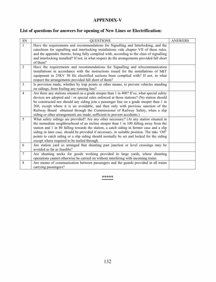
132
APPENDIX-V
List of questions for answers for opening of New Lines or Electrification:
SN QUESTIONS ANSWERS
1 Have the requirements and recommendations for Signalling and Interlocking, and the catechism for signalling and interlocking installations vide chapter VII of these rules, and the appendix thereto, being fully complied with, according to the class of signalling and interlocking installed? If not, in what respect do the arrangements provided fall short of them?
2 Have the requirements and recommendations for Signalling and telecommunication installations in accordance with the instructions issued for the installations of S&T equipment in 25KV 50 Hz electrified sections been complied with? If not, in what respect the arrangements provided fall short of them?
3 Is provision made, whether by trap points or other means, to prevent vehicles standing on sidings, from fouling any running line?
4 Are there any stations situated on a grade steeper than 1 in 400? If so, what special safety devices are adopted and / or special rules enforced at those stations? (No station should be constructed nor should any siding join a passenger line on a grade steeper than 1 in 260, except where it is un avoidable, and then only with previous sanction of the Railway Board obtained through the Commissioner of Railway Safety, when a slip siding or other arrangements are made, sufficient to prevent accidents.)
5 What safety sidings are provided? Are any other necessary? (At any station situated in the immediate neighbourhood of an incline steeper than 1 in 100 falling away from the station and 1 in 80 falling towards the station, a catch siding in former case and a slip siding in later case, should be provided if necessary, in suitable position. The take ‘Off’ points to catch siding or a slip siding should normally be set and locked for the siding except where required to be trailed through.
6 Are station yard so arranged that shunting past junction or level crossings may be avoided as far as feasible?
7 Are shunting necks for goods working provided in large yards, where shunting operations cannot otherwise be carried on without interfering with incoming trains
8 Are means of communication between passengers and the guards provided in all trains carrying passengers?
*****

133
APPENDIX-VI
In case of introduction of new type of locomotive
Joint Safety Certificate
Certified that it is safe to run ..............................(Particulars of locomotives and rolling stock proposed to be run) not exceeding.....................units (in case of locomotives) coupled together on the section (station)................................. to .................. (station) from............................(K.m.) to....................... (K.m.) of the Railway at a maximum speed of......................(Km.p.h.) against a maximum speed of...................(Km.p.h.) certified by R.D.S.O. subject to the following speed restrictions and conditions: (a) Speed Restrictions-
Sl.No. From Km. To Km. Nature of restriction Brief reason for restriction
(b) Special Conditions- ............................................................................................................................. .............................................................. C.M.E. C.E. C.E.E. C.S.T.E. C.O.P.S. Note: (1) When the speed of a loco/rolling stock is to be increased the C.O.P.S. and C.S.T.E. should be associated when the increase in speed is contemplated over the maximum sanctioned speed for that category of train (passenger or Goods over a particular section. (2) C.E.E. should countersign whenever Electric loco is involved.
*****
134
ANNEXURE-VII
Rules for sanction of opening of new railways:
Under Ministry of Railways, (Railway Board), notification 8th October,2000, G.S.R. 762(E), in exercise of powers conferred by sections 28, 29, & 198 of Railway Act 1989 (24 of 1989), the Central Government, made the following rules: 1) i) These rules may be called the (Railway Opening for Public carriage of passengers)
amendment Rules 2001. ii) They shall come into force on the date of their publication in the Official Gazette. 2) In the Railways (Opening for public carriage of passengers) Rules, 2000, in Chapter-II Rule(1), Chapter VI Rule 21(1), 21(2), 21(3), Rule 22(1) and chapter VII Rule 25(2), 25(5) shall be read as follows and Chapter I Rule 1(2), Chapter VI Rule22(2) shall stand deleted. Chapter IV “Sanction to open railway for public carriage of passengers”, of the “Rules for Opening of New Railways or section of a railway for public carriage of passengers” is reproduced as below: Rule- 21. Sanctioning of opening of railway: (1) The Central Government may, after considering the Inspection Report of the Commissioner, confirm, modify or cancel the sanction given under rule 22(1) subject to such conditions, alterations or relaxations as may be necessary. (2) While confirming the opening of any railway, the Central government shall give consideration to the suggestions or conditions subject to which the Commissioner has opened the railway. (3) Where the Commissioner has not recommended the opening of any railway or has proposed to cancel the sanction already given, the Central government shall confirm or modify the recommendation of the Commissioner as necessary and shall direct the Railway Administration concerned to remove the defects or short comings reported by the Commissioner. (4) Where the defects or shortcomings are such that they cannot be removed unless the railway or a portion thereof is dismantled, then the Central Government shall order the closing of railway forthwith for the public carriage of the passengers. (5) Railway line, which is closed for the public carriage of passengers under section 25, shall not be reopened unless it is duly inspected b the Commissioner in advance with the provisions of Chapter IV of these rules and the commissioner recommends the reopening of such railway line. (6) The actual date of opening of a new railway line or a section or a portion of such line for passenger traffic shall be notified by the concerned General Manager, after consulting the Central Government, by notification in the Official Gazette, and in the local news papers of the areas through which the railway line passes.

135
Rule- 22. Opening of railway by Commissioner: (1) The Commissioner, after inspection, may under section 28 sanction the opening for public carriage of passengers of new lines of railway within the respective circles subject to the conditions as the Commissioner may impose. (2) On receipt of the Inspection Report of the Commissioner, the Central Government may confirm, modify or cancel the sanction given under sub-rule (10 subject to such conditions, alterations or relaxations as may be considered necessary. Rule- 23. Sanction to use locomotive engines & rolling stock on new line: (1) The Commissioner may sanction the use of locomotive engines, rolling stock or any other motive power under section 27 which is already running on any zonal Railway, or any division or section of any non-Government railway, or any new lines in accordance with the provisions of Indian Railway (Open Lines) General Rules, 1976 or orders on the subject issued by the Central Government from time to time. (2) Before according sanction under sub-rule (1), the Commissioner shall ascertain that the application of the Indian Railways (Open Lines) General Rules, 1976 by the concerned railway administration which operates the line has been previously sanctioned and notified in the Official Gazette.
*****

136
APPENDIX-VIII List of Infringements of maximum and minimum dimensions:
List of deviations as certified and signed by the General Manager I do hereby certify: i) that the Maximum dimensions for railways in India have in every case been worked to, with the
exceptions detailed in the statement herewith annexed, also that the Standard dimensions will be observed in future, and that no work or structure infringing the standard dimensions will hereafter be permitted without the sanction of the Central Government. (In the statement showing the cases in which the maximum and minimum dimensions have been infringed, full details for each case must be given, in the form given below, with the explanation of the necessity for such infringements and a reference to the authority under which it was permitted. If there have been no infringements of the maximum and minimum dimensions the words “with the exception detailed in the statement herewith annexed” should be omitted or struck out. This form XVII shall be annexed to the certificate)
ii) that each bridge is of such design, dimension and construction as will enable it to bear the dead load of the structure itself (with flooring, roadway, permanent way etc. complete), and in addition thereto, the equivalents of the live loads specified in the rule prescribing Standards of Design and loading for Railway bridges, without exceeding the maximum permissible stress on the available material in any member or portion of the structure.
iii) that more than two engines shall not under any circumstances be allowed at one time on the same track of one span of any bridge.
iv) that every coaching vehicle constructed or procured for the use of the railway in mail and passenger trains is, and shall be provided with vacuum/air brake and effective means of communication between passengers, guard and driver. (This part of certificate is nor necessary for those light lines on which the use of vacuum or air brake has not been insisted upon.)
v) that one compartment or such number of berths or seats, as the railway administration may think fit, of a second class carriage of every train carrying passengers shall be reserved for exclusive use of females.
vi) That the railway shall be worked on the system known as Absolute Block System in accordance with the regulations prescribed in Chapter VIII of the General Rules for railways in India.
vii) that the electric traction equipment can be used for public carriage of passengers without danger to public and that the rules for design and inspection of equipment for electric traction (of Chapter VIII of these rules) have been complied with. (This shall be included only when applicable.)
viii) that the signalling and telecommunication equipment have been installed in accordance with the approved instructions and they are safe for passing traffic.
ix) that……….has been delegated to accompany the Commissioner of Railway Safety on his inspection and all information supplied or engagements entered into by him shall bear my authority.
(Signed) The General Manager
*****
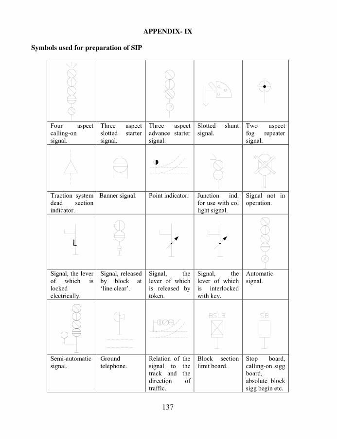
137
APPENDIX- IX
Symbols used for preparation of SIP
Four aspect calling-on signal.
Three aspect slotted starter signal.
Three aspect advance starter signal.
Slotted shunt signal.
Two aspect fog repeater signal.
Traction system dead section indicator.
Banner signal. Point indicator. Junction ind. for use with col light signal.
Signal not in operation.
Signal, the lever of which is locked electrically.
Signal, released by block at ‘line clear’.
Signal, the lever of which is released by token.
Signal, the lever of which is interlocked with key.
Automatic signal.
Semi-automatic signal.
Ground telephone.
Relation of the signal to the track and the direction of traffic.
Block section limit board.
Stop board, calling-on sigg board, absolute block sigg begin etc.

138
Half bracket. Side bracket or straight post.
Tee bracket. Suspended doll. Point can be shown thus.
Point - Hand - Worked.
Point - Spring 1 - Way.
Point - Spring 2 - Way.
Point worked from signal box
Point without lock with bar (1-lever).
Point without lock with bar (2-levers).
Point with lock and bar (1-lever).
Point with lock and bar (2-levers).
Point with lock without bar (1-lever).
Point with lock without bar (2-levers).
Slotted joint control.
Scotch block. Derailer (Arrow shows direction of derailment).
Trap point, single switch with guard rail.
Movable switch diamond.
Single slip. Double slip. Released by token.
Released by key on token.
Released by key from signal box.

139
Insulating rail joint, track circuit in both direction.
Insulating rail joint, track circuit on left, none on right.
Insulating rail joint, track circuit on right, none on left.
Track Circuit portion (single line plans).
Digital axle counter.
Analogue axle counter.
Impedance bond.
Relaying or cut section in track circuit.
Traffic direction.
Over bridge.
*****

140
APPENDIX- X
Track circuit record cards: for DC track circuits, Card Number S&T/TC-1
Card No. S&T/TC-1 .............................Railway
Signal and Telecommunication Department
TRACK CIRCUIT TEST RECORD CARD
1. Station or Section of line 2. Track circuit No. 3. Type of relay 4. Date installed 5. P.U. Volts 6. D.A. Volts 7. P.U. Current 8. D.A. Current 9. Resistance of relay 10. Length of track Circuit (m) 11. Length of Leads from feed end to track (m) 12. Length of leads Relay to Track (m) 13. Type of Ballast 14. Type of Track Feed. 15. Size of track feed conductor 16. Size of conductor to Relay 17. Type of sleeper and condition 18. Type of insulated joints 19. Number of Ash pits in track 20. No. Of L.xings in track 21. Number of insulated joints in Track Ballast Resistance = (VF + VR)/ (IF + IR)
Current at Relay = Voltage at Relay Terminal / Resistance of Relay
22. Date 23. Weather 24. Condition of ballast wet, Damp or Dry 25. Percentage of ballast clear of rails 26. Drainage of track Good, fair or Bad 27. Condition of rail surface 28. Condition of Bonds & Jumpers 29. Condition of insulated joints 30. Condition of Track Battery
Track Feed End
31. Feed resistance 32. Voltage at battery/track feed voltage 33. VF Voltage at rails 34. IF current at rails
Relay End
35. VR Voltage at rails 36. Voltage at Relay Terminals 37. IR current at relay terminals 38. Ballast resistance 39. Rail resistance and Bond resistance 40. Drop shunt value 41. Pickup shunt value 42. Signature of Section Engineer/Signal Signature of Senior Section
Engineer/Signal
Station...........................................
*****

141
APPENDIX-XI
AC Track circuits, Card number S&T/TC-2
Card No. S&T/TC-2 .............................Railway
Signal and Telecommunication Department
TRACK CIRCUIT TEST CARD
2. Station or Section 2. Track circuit No. 3. Type of relay Siemens/Vane type
4. Date installed
5. Frequency: 50/83-1/3 Hz 6. Control phase 7. Local phase 8. Local phase rated P.U. Voltage 9. Control phase rated P.U. Voltage 10. Control phase D.A. Volt 11. Length of track Leads..... (feed end) 12. Resistance of feed end lead 13. Length of track Leads..... (Relay end) 14. Resistance of Relay lead 15. Control P.U. current 16. Control D.A. current 17. Type of sleeper and condition 18. No. of block joints 19. Number of Ash pits 20. No. of Level crossings 21. Length of track circuit 22. Type of Ballast Values for a 50 Hz track circuit Local phase Volt 130B for motor 110V for vane type Local phase current 50A Track phase voltage 18V for motor For vane type Track phase current 0.25A 23. Date 24. Weather 25. Condition of ballast 26. Percentage of ballast clear of rails 27. Drainage of track Good, fair or Bad 28. Condition of rail surface 29. Condition of insulation joints 30. TR Control phase voltage primary 31. Tapping on secondary F/T. 32. VF Voltage feed end rails 33. IF current to track 34. VR Voltage at rails relay end 35. Voltage at Relay Terminals 36. IR current at relay terminals 37. Tapping on primary R/T 38. Tapping Secondary R/T 39. VRS voltage secondary terminals R/T 40. IR Current to Relay terminals 41. VL voltage local 42. Phase angle 43. Ballast resistance 44. Rail resistance 45. drop Shunt value 46. Pick up shunt value 47. Signature of Section Engineer Signal 48. Signature of Senior Section Engineer Signal 49. Station
*****

142
APPENDIX-XII
Jeumont Track circuits, Card number S&T/TC-3 Je
um
on
t ty
pe
trac
k c
ircu
its,
Car
d n
um
ber
S&
T/T
C-3
..
....
....
....
......
....
....
..R
ailw
ay
MA
INT
EN
AN
CE
CA
RD
- JE
UM
ON
T T
RA
CK
CIR
CU
IT
Nam
e of
stat
ion S
ing
le r
ail/
Do
ub
le r
ail
Tra
ck c
ircu
it N
o..
....
....
....
....
Dat
e of
inst
alla
tion..
....
....
....
Tra
nsm
itte
r
(Rel
ay e
nd
co
nn
ecti
ons
(for
double
rai
l tr
ack C
ircu
its)
Imped
ance
, b
on
d f
eed
en
d o
r R
ecei
ver
B
1
B1 N
1
B1
B1
B2
N1
B2
Fee
d e
nd t
ran
sform
er......
R
ecei
ver
ter
min
al
Imped
ance
, b
on
d r
elay
en
d...... B
11
B1
I.B
. te
rmin
als
Rec
eiver
....
...................
Rel
ay..
....
................... A
C
I.
B.
stra
ps
S.N
o.
Dat
e W
eath
er,
dry
or
wet
Su
pp
ly V
olt
age
Imp
uls
es/m
inu
te T
rack
pea
k V
olt
age
(in
Vo
lts)
Tra
ck r
elay
Cu
rren
t T
rain
Sh
un
t
in o
hm
s
F
eed e
nd
R
elay
end
m
a
ma
f
eed
and
Rel
ay e
nd
Note
: tr
ack v
olt
age
to b
e m
easu
red
wit
h i
nte
gra
tor.
This
car
d s
hal
l be
kep
t at
the
rela
y e
nd o
f ea
ch t
rack
cir
cuit
.
*****

143
APPENDIX-XIII Cable insulation Resistance test sheet Main/Tail cables.
Form No. SG/IRC .............................Railway
Station.......................................... Cable insulation Resistance test sheet
Main/Tail* cables
1. Location from....................................................To........................................ 2. Cores..................................................... 3. Size........................................................ 4. Grade 250/440/650/1100V* 5. Length..................................................... 6. Type Unscreened/Screened/Power* 7. Insulation PVC 8. Date of Installation/commissioning........................................... 9. Name of the manufacturer......................................................................
*Strike out which ever is not applicable
Core No. Or Designation Date of Test and whether@
Temperature: Remarks: Signature: @ write wet, damp or dry
*****

Indian Railway Signal Engineering Volume-III
Section-I
SYSTEM OF MECHANICAL SIGNALLING (SINGLE WIRE)

Indian Railway Signal Engineering Volume-III
2
CHAPTER- I
SYSTEM OF MECHANICAL SIGNALLING & SINGLE WIRE SYSTEM
OPERATING DEVICES: DIRECT LEVER LOCKING INTERLOCKING
FRAME
1.0 System of mechanical signalling: System of mechanical signalling is termed as orthodox i.e. “conforming to established views”, which in turn establishes that this system of signalling is basic to present day system of electronic interlocking signalling. Under the system of Single wire signalling, points are operated and locked using levers through rods as media of transmission, signals are operated by levers through single wire as media of transmission, and correspondence of the operation between lever and the point or signal is monitored electrically for signal and mechanically by detector. Interlocking is associated with levers within lever frame withholding pulling of any lever not warranted to be pulled jeopardising safety. The system has been working well with restricted speed of the trains. However with the speed increasing, a faster operating system is required to be introduced, which has emerged with the introduction of electrical and electronic system of interlocking. Systems in use are, i) Single wire and ii) Double wire. Under Single wire system of mechanical signalling i) Direct lever locking interlocking frame to RDSO specification number (SA 530) and ii) Catch handle locking interlocking frame to RDSO specification number (SA 1101) are in use. In addition ground frames are also used for level crossing gate control and local operation of signals and points. Double wire system of mechanical signalling is discussed under Section-II of this book.
1.1 Direct lever locking interlocking frame: Major parts of Direct Lever Locking Interlocking Frame are , i) Lever, Catch Handle, Catch Handle Rod, Number Plate & Catch Handle Box, ii) Quadrants Left Hand, Right Hand, Intermediate under different design and specifications, iii) Quadrant support ‘T’ bar, iv) Standard and ‘Bearing Cap’, v) Brackets, for support of single channel locking box and for support of four channel locking box under different design and specifications, vi) Front Tail for point and signal levers and back tail, under different design and specifications, vii) Lever shoe, viii) Shoe cover, ix) Bearing cap, x) Shaft cap, xi) Shaft collar, xii) Shaft, xiii) Locking Plunger, xiv) locking boxes for 4 channel- 5 levers, 4 channel-7 levers, 1 channel-5 levers and 1 channel-7 levers, xv) Back Weight, xvi) locks of sorts, xvii) Interlocking bars of 16mmx12mm, and xviii) Right End (Cover piece to be provided on right end of the frame).
1.1.1 Lever: Lever, the tool to gain mechanical advantage can be classified in order in which i) fulcrum lies between the load and effort, ii) load lies between the fulcrum and iii) Effort lies between the load and fulcrum. When Load and power impressed on a simple machine keep it in equilibrium, the ratio of the load to power is called as mechanical advantage. Accordingly if the effort arm of the lever of which fulcrum lies between the load and effort, is

3 Pramod P. Goel
longer than the load arm the mechanical advantage shall be greater than unity i.e. operation of signal or point shall be possible to be done by applying lesser effort. The shape of the lever is flat rectangular iron bar with a handle on its top, fastened with lever shoe, with bolts and nuts [Figure 1.1.1 & 1.1.3]. A Catch handle is loosely connected to lever with a pin at the top. A round Lever Handle Rod is held with the Catch Handle, running parallel to the smaller face of the lever up to the quadrants passing through the Catch Handle Box. The catch handle box is fastened with the catch handle rod with nuts adjusted such as to rest on the quadrant with catch handle released due to gravity and to clear the reed of the quadrant on being lifted when catch handle is pressed against lever handle. The Catch Handle Box encases the lever such as to hold the lever in its last operated normal and reveres position when the catch handle is released. As and when it is required to move the lever to either position the catch handle shall be pressed against the lever handle to lift the catch handle box so much so the catch handle box is lifted above the reeds of the quadrant. The portion of the lever between the lever-handle and the shaft on which lever shoe is attached, is the effort arm of the lever. A tail is fixed with the lever shoe with bolts and nuts to which the operated function is attached. The load arm of the lever is the portion of the lever between shaft on which the lever shoe is attached and the tail end. Accordingly lever is from catch handle to tail, running through lever shoe while the shaft is the fulcrum. A number plate is fastened to the lever with nut and bolt to depict the number of the lever. A lever collar is metal plate designed such that when inserted into the lever handle shall not permit the catch handle to be pressed and as such in turn shall not allow the lever to be moved to avoid inadvertent operation of the lever, jeopardising safety. The angular throw of the lever is 270. 1.1.1.1 Slackness permissibility: To accommodate all joints and permissible margins, the Catch Block lifted can move 12 mm (½") on the quadrant reed from the edge, if the interlocking does not permit the operation of the lever. 1.1.2 Quadrants: Part of the effort arm of the lever protrudes above level of the first on which the Cabin Man stands and operates levers while balance part of the lever is below ground level which is housed in the lever shoe and fastened rigidly with it using bolts and nuts. i) Each lever fastened to the lever shoe which is required to be equidistant by providing Shaft Collar on the shaft in between each lever shoe. ii) Same distance between the levers is maintained at the
NUMBER PLATE
LEVER COLLAR
CATCH HANDLE
CATCH HANDLEROD
LEVER HANDLE
PART LEVER Figure1.1.1
Part lever of direct interlocking type
lever frame

Indian Railway Signal Engineering Volume-III
4
first floor level as well to enable the levers move in between equidistant channel created between two quadrants. This maintains each lever, vertical, maintaining equal distance at the lever shoe level as well as at the floor level for maintaining steady movement of the levers. iii) The levers are also required to be held rigidly in last operated position.
3'-218
"
10"
BRACKET (4 CHANNEL)
BRACKET
(SINGLE CHANNEL)
CATCH BOX
F L O O R L E V E L
CATCH HANDLE ROD
CATCH HANDLE
LEVER HANDLE
NUMBER PLATE
LEVER
QUADRANT SUPPORT
'T' BAR
QUADRANT SUPPORT
'T' BAR
LOCKING BOX 4 CHANNEL
LOCKING PLUNGER
LOCKING BOX / CHANNEL
BEARING CAP
Figure 1.1.3 Standard direct interlocking type
Three type of quadrants are used at the ends of lever frame named as i) Quadrant Left Hand and ii) Quadrant Right Hand to close the ends and remaining all iii) Intermediate quadrants to

5 Pramod P. Goel
maintain equal space and a channel to accommodate the lever to move normal to reverse and vice versa. A Quadrant support ‘T’ bar is fixed onto the standards at front and back running parallel to each other to hold all such quadrants fastened with the ‘T’ bar. 1.1.3 Standard: [Figure 1.1.3] Standard made of cast iron is placed and fastened on two steel girders with bolts and nuts absolute right angles to the alignment of girders which is parallel to the side walls of the cabin basement, at interval of 5 or 7 levers in between each pair depending upon type of interlocking box proposed to be used. Accordingly Standards are placed out side first and last levers. The pitch of levers is 125 mm (5"). The steel girders are rigidly placed on cement concrete Bed Blocks which are placed within the side walls of the cabin basement. Stanchions are provided in between both ends of the girder as and where required for support, depending upon span. The ‘T’ bar runs through on top of all the standards to hold quadrants and also help the standard maintain vertical. Brackets for support of four channel locking box are bolted with the front side of the standard and for support of single channel locking box in the rear on space indicated. The shaft, meant to bear the shoe lever runs through all standards end to end and is held in position rigidly by ‘Bearing Cap’ which is fastened at the space provided in the standard as shown in the figure. 1.1.4 Lever shoe: [Figure 1.1.4] Lever shoe is monolithic block with housing for lever, front tail, back tail and arrangement to rest itself on the shaft with the ‘Shoe Cover’ fastened firmly using bolts and nuts, able to rotate about the shaft with the movement of the lever. 1.1.5 Tail: The Front Tail used for signal shall impart stroke as 250mm (9-1/4"), 10-5/8", 300mm (1' 0"), 1' 3/8", 1' 2-3/4" and for points 150 mm (5-7/8") and 200 mm (8"). The stroke to be provided to rod run for operation of points in Broad Gauge (BG) is 200 mm (8") for 125 mm (4½") opening of points.
Back Weight is provided on the Back Tail to assist in withdrawal effort of the wire run while the lever is being put back to normal. Mechanical advantage for 200 mm (8") stroke is 5.4.
SHOE COVER
Figure 1.1.4 (Detail of ‘X’ of figure 1.1.3)
Lever Shoe & Shoe Cover for direct
interlocking frame
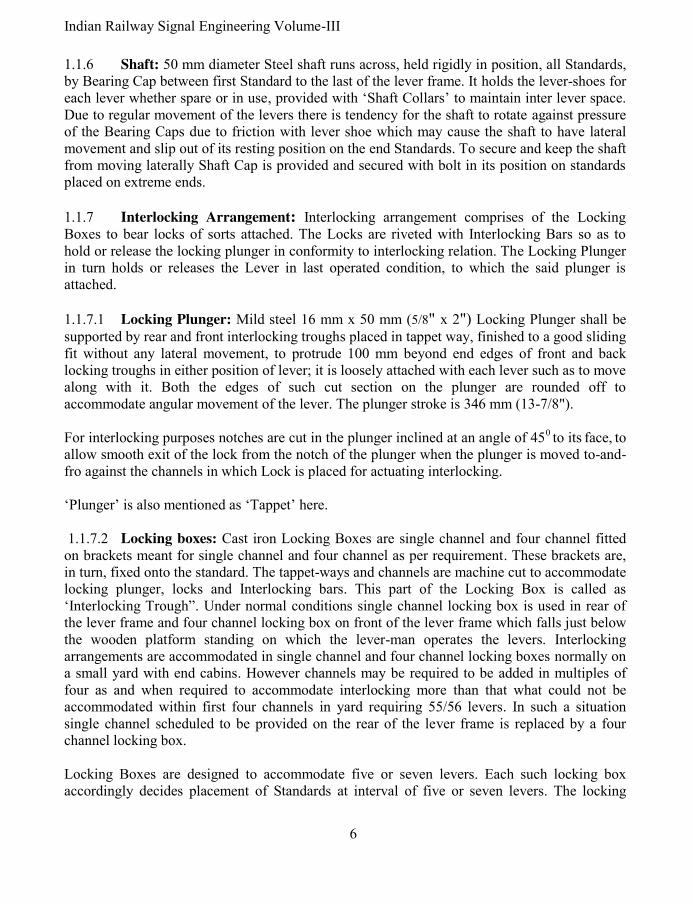
Indian Railway Signal Engineering Volume-III
6
1.1.6 Shaft: 50 mm diameter Steel shaft runs across, held rigidly in position, all Standards, by Bearing Cap between first Standard to the last of the lever frame. It holds the lever-shoes for each lever whether spare or in use, provided with ‘Shaft Collars’ to maintain inter lever space. Due to regular movement of the levers there is tendency for the shaft to rotate against pressure of the Bearing Caps due to friction with lever shoe which may cause the shaft to have lateral movement and slip out of its resting position on the end Standards. To secure and keep the shaft from moving laterally Shaft Cap is provided and secured with bolt in its position on standards placed on extreme ends.
1.1.7 Interlocking Arrangement: Interlocking arrangement comprises of the Locking Boxes to bear locks of sorts attached. The Locks are riveted with Interlocking Bars so as to hold or release the locking plunger in conformity to interlocking relation. The Locking Plunger in turn holds or releases the Lever in last operated condition, to which the said plunger is attached.
1.1.7.1 Locking Plunger: Mild steel 16 mm x 50 mm (5/8" x 2") Locking Plunger shall be
supported by rear and front interlocking troughs placed in tappet way, finished to a good sliding fit without any lateral movement, to protrude 100 mm beyond end edges of front and back locking troughs in either position of lever; it is loosely attached with each lever such as to move along with it. Both the edges of such cut section on the plunger are rounded off to accommodate angular movement of the lever. The plunger stroke is 346 mm (13-7/8").
For interlocking purposes notches are cut in the plunger inclined at an angle of 450 to its face, to allow smooth exit of the lock from the notch of the plunger when the plunger is moved to-and-fro against the channels in which Lock is placed for actuating interlocking. ‘Plunger’ is also mentioned as ‘Tappet’ here.
1.1.7.2 Locking boxes: Cast iron Locking Boxes are single channel and four channel fitted on brackets meant for single channel and four channel as per requirement. These brackets are, in turn, fixed onto the standard. The tappet-ways and channels are machine cut to accommodate locking plunger, locks and Interlocking bars. This part of the Locking Box is called as ‘Interlocking Trough”. Under normal conditions single channel locking box is used in rear of the lever frame and four channel locking box on front of the lever frame which falls just below the wooden platform standing on which the lever-man operates the levers. Interlocking arrangements are accommodated in single channel and four channel locking boxes normally on a small yard with end cabins. However channels may be required to be added in multiples of four as and when required to accommodate interlocking more than that what could not be accommodated within first four channels in yard requiring 55/56 levers. In such a situation single channel scheduled to be provided on the rear of the lever frame is replaced by a four channel locking box. Locking Boxes are designed to accommodate five or seven levers. Each such locking box accordingly decides placement of Standards at interval of five or seven levers. The locking

7 Pramod P. Goel
arrangement in this type of interlocking frame is bulky so much so that workability restricts the use up to 55 (5x11) – 56 (7x8) levers warranting to go for catch handle type of lever frame. Pitch of the channels is measured from centre line running across channel to channel and is
110 mm (4-3/8"). Each channel is designed to accommodate three Interlocking Bars running
right angle to the Plunger alignment at the bottom of the channel for which the space kept is 60 mm (2-3/8"). The width at the top of channel is kept as 70 mm (2-7/8") to accommodate three Interlocking Bars running above and across plunger within channel.
1.1.7.3 Locks, Conflicting notches and Interlocking: The Lock has two dimensions, one its overall length to be just fit within the channel of the locking Box and second the lock actuating part which varies from channel to channel. Both combined as one piece is termed as ‘Lock’. With 110 mm channel pitch as against 346 mm stroke the plunger shall cross at least three channels (110 x 3 =330). If the notches in the plunger (tappet) were made of one and the same size each against first two or three channels of the locking trough and all the three channels were provided with different interlocking arrangements, the lock in first channel shall insert into the notch of the plunger and foul the interlocking provided in the first channel while this may also happen with the second or third channel lock. To avoid such a situation to arise, each channel has been prescribed with the size of the ‘Lock’ of each Channel [Figure 1.1.7.3(i)] for locking arrangements in all the three channels interacting with one and the same plunger, in size decreasing from largest size of Lock to the lowest size, for “normal” locking and decreasing sizes for “back locking”; while the corresponding notch in the plunger shall be smallest to interact with the lock in last channel, decreasing upwards to largest, which shall ensure that the largest sized lock in the first channel does not enter into the smallest sized notch in the plunger, true for each other channels. This arrangement of notches takes care of Conflicting Notches. However the said notch in the plunger shall not reach up to last i.e. fourth channel. This calls for use of Locks in channels of sizes different for each channel. Accordingly the locks in the channels ‘A’, ‘B’, ‘C’ & ‘D’ of the trough put on front side of the Lever Frame shall be provided in sizes 1/4th, 2/4th & 3/4th of full size and last being full size. The notch cut into the Locking Plunger is tapered at 450 to the face of the plunger to facilitate smooth exit of the Lock from the notch of the Locking Plunger. Accordingly the size of the Lock is reduced by 12 mm and the Lock face only is measured for all practical purposes. Total length of the Lock being 70mm (2-7/8"), actual dimensions work out to be 15 mm (5/8"), 30 mm (1-1/8"), 40 mm (1-5/8") and 58 mm (2-3/8") corresponding to the channels ‘A’, ‘B’,
Figure 1.1.7.3(i)
Sizes of the Locks and
corresponding Notches

Indian Railway Signal Engineering Volume-III
8
‘C’, & ‘D’ of the trough and the travel of the locking plunger is from Channel ‘A’ to Channel ‘D’. It may be noted that these sizes given here are of that part of the lock which buts against the face of the plunger notch excluding 12 mm component measured parallel to the face of the Locking Plunger in each Lock piece, the portion of the lock inclined at 450 to the face of the lock to match with the notch cut in the plunger to facilitate smooth exit of the lock from the corresponding notch in the plunger [Figure 1.1.7.3(i) & 1.1.7.3(iii)]. As the Locking Plunger shall move forward, the smallest notch in the Locking Plunger shall travel across larger size of the Locks in succeeding Channels reaching to the last Channel, thereby eliminating conflict with the locking. To avoid conflicting notches, while actuating interlocking, it is pertinent to note that in case of
interlocking relation ‘Locks Normal’ the sequence of size of the notches in Locking Plunger
(Tappet), 1/4th of the Lock size, is kept increasing corresponding to first (topmost) channel,
ending on the last channel at full Lock size of notch, keeping the tapered part of the Lock on
upper side of the given channel. While at the same time the locks of sizes decreasing from the
full sized lock to smallest sized lock in the last channel. With the movement of the Locking
Plunger (Tappet) from normal to reverse the notch cut falls within in the Locking Box, moves in
direction from inside Locking Box to tending towards going out of the locking Box along with
the movement of the locking Plunger. It is this movement of the Lock which actuates the
interlocking.
In case of the ‘Requires’ interlocking relation, notch cut in the plunger, has to be out side the
Locking Box, enters into the Locking Box. Accordingly, the sequence of lock sizes and the
direction of the angle/tapered shape of the Locks in the channels shall be reversed starting
from full size lock in first (topmost), decreasing size to lower channels to the last channel to be
1/4th.
As and when the Interlocking Bars with Locks riveted, are placed in the bottom of the channels, Locking Plungers are placed in position, all Interlocking bars are placed on the top of the Locking Plungers, independent Locks not riveted to the Interlocking bars, used by pushers, cannot be put loose into the channel. Such Locks are subject to jump off the position where placed. To ensure this not to happen such locks are riveted to an independent Interlocking Bar large enough to be held under at least two adjoining Locking Plungers where space to accommodate the Interlocking Bar is there and is short enough to remain under for to & fro movement, which shall hold the loose Lock in position or if there is no such space, the interlocking bar shall be riveted with the lock to be at the top. In case the Interlocking bar is on top of the Lock, Cover Brackets are screwed with the body of the trough such as to ensure that the Lock does not jump off the position.
Figure 1.1.7.3(ii) Diamond-
Direct special interlocking

9 Pramod P. Goel
Special interlocking is achieved through ‘Diamond’ with associated Lock pieces [Figure1.1.7.3 (ii)]. The mild steel diamond as called in black smith’s language is in two pieces the projected part of one piece slides smoothly in the corresponding matching cavity in the other piece. Each arm of the Diamond is inclined to right angles with adjoining arm to give 450 angle of contact. The upper and lower part of the set are capable of moving sideways as well the set can also move upwards and down wards as whole. A sample of a part of an Interlocking Chart is shown under Figure 1.1.7.3(iii). Since the diamond is in two pieces it requires an even bed under it to function properly. It may be seen in Channel ‘C’ that Interlocking Bar bottom-1, depicted in two lines and riveted showing two circles on the Lock, runs between locking Plunger number ‘28’ and ‘31’. Second bottom-2 Interlocking Bar runs between lever ‘26’ and ‘31’ and Interlocking Bar bottom-3 runs between levers ‘28’ and ‘30’, all three together make perfect bed for the Diamond. The Diamond being loose is also susceptible to jump off under pressures. To prevent such a situation two dummy pieces are tied together with top Interlocking Bar depicted as single line and riveted shown as two solid rectangular shapes to hold the Diamond in place.
26 27 28 29 30 31
CH:B
CH:C
CH:D
Figure1.1.7.3(iii) Depicting Special interlocking arrangements
Channel ‘B’ has been shown having no interlocking relations. Channel ‘C’ shows partial interlocking relations relevant only to understand features showing Locks and Interlocking

Indian Railway Signal Engineering Volume-III
10
Bars. Two Interlocking relations viz. 26 x 31 either way and Special Interlocking 30 requires 27 when 29 is normal, 30 requires 31 when 29 revered and 30 x 29 either way. As the lever ‘30’ is pulled the Lock attached with bottom-3 Interlocking bar attached to lever ‘30’ shall pull the lock butting with the lever ‘28’ and squeeze the Diamond which in turn shall try to push the Lock connecting other lock with top Interlocking bar-3, into the notch against it but nothing shall happen till the lever ‘27’ is pulled to align its notch against the Lock. As the Lever ‘27’ is pulled first and then the lever ‘30’ is pulled while the lever ‘29’ is normal the Lever ‘27’ shall get locked in reversed position while at the same time the lever ‘29’ also shall get locked in normal position. Similarly when lever ‘29’ is reversed and lever ‘30’ is pulled interlocking shall work only when the lever ‘31’ also has been pulled. In this case also lever ‘30’ shall lock lever ‘31’ as well as lever ‘29’ when all the three levers have been pulled. It may be observed that the lever ‘29’ also gets locked either way. It may be noticed that in this case there is no notch in the lever ‘28’ corresponding to the channel ‘C’ as such there is no interlocking relation with this lever which works as dummy support for actuation of the locking with respect to the present relation in question. To ensure loose locks do not jump off the trough, these Locks are held in position, the lock is riveted in bottom with a piece of Interlocking Bar either end of which is put under the adjoining Locking Plungers, where possible due to availability of space or otherwise by riveting Interlocking Bar on top of the lock or by riveting two Dummy pieces to the Interlocking Bar on each end and putting over the Lock/Diamond as discussed above. After this Cover plates are screwed with Locking Box over such Interlocking bars holding single Lock. 1.1.7.4 Numbering of the channels: Locking Box channels are numbered from top to bottom when looked at the Interlocking Chart, which in effect means numbers start from first channel of rear end locking box to the last channel of the lever frame. Alphabets are used for numbering staring with ‘A’ in capital only. Accordingly rear end Locking Box single channel shall be numbered as ‘A’ which shall continue with front end Locking Box shall be numbered as ‘A’, ‘B’, ‘C’ & ‘D’. More channelled interlocking boxes may be used and numbered accordingly when required. 1.1.7.5 Security of Interlocking against unauthorised interference: The trough is covered by the Cover Plates slid under the Stud Pins fixed on the top of Trough’s side walls through the key holes in the Cover Plate. These Cover Plates covering each trough, placed under the Stud Pins, butting to the end of last Cover Plates with the facing edge of the next Cover Plate from left end to right hand, are terminated by a plate matching to the Cast iron Right End piece attached to the last Locking Box Placed at the extreme right hand. A hole in the cover plate matching the shape and size of the Right End piece and in the Right End Piece accommodates a Cotter Pin through the said hole in the Cover Plate and the Right End piece and sealed by a person authorised to test the interlocking after completion and testing of the Interlocking. The workman ship and the arrangement shall be such that it shall not be possible to open the Cover Plates without removing the seal and the cotter bolt and sliding the cover plates to align the larger orifice part of the key hole, out of the studs. The Left End is 75 mm (2-7/8") long piece

11 Pramod P. Goel
added to the Trough at the left hand of first Interlocking trough without any locking arrangement. 1.1.7.6 Locks of sorts: Locks are iron cast to the desired shapes and sizes meant for Normal, Requires and Conditional Interlocking. The Conditional Interlocking is also termed as Special interlocking. While Locks for ‘Normal’ and ‘Requires’ interlocking relations are used in different sizes as shown in figure 1.1.7.3(i), the set of locks for Special Interlocking is in five pieces called in blacksmith’s language as diamond and associated lock pieces. 1.1.7.7 Interlocking Bars: Mild steel Interlocking Bars are meant to hold the Locks riveted with it, as per requirement depicted in the Interlocking chart. Each channel of the trough can accommodate three interlocking bars under and three at the top of the locking plunger, each being of the size 16 mm x 12 mm (3/4" x 3/8"), the size of the channel at the bottom being 60 mm (2-3/8") enough to accommodate three interlocking bars [Figure 1.1.7.7]. Since the Locking Plunger rests on tappet way which is above the bottom cavity holding the Interlocking Bars, it shall not rub against the plunger. The thickness of the locks is such that when riveted to the bottom Interlocking Bar the lock shall also cover the thickness of the locking plunger. Similarly when riveted to the top Interlocking Bar it shall cover the thickness of the locking plunger. Interlocking bars shall normally be used in pull arrangement to avoid buckling. However as and when these are used in push there is chance of buckling and some times getting out of notch when the bar is long enough. In case the Interlocking bar is larger than 10 to 12 levers dummy pieces/carrier locks should be riveted with such interlocking bars to hold the interlocking bar avoid buckling upside or sideways and maintaining alignment. 1.2 Ground lever frame: Mechanically operated lifting barrier boom are lifted and downed with the help of winch and loop of wire rope. The locking of the boom once downed to close the level crossing gate and taking Off, of the signal is carried out using levers provided in a Ground Lever Frame. There shall be one lever for locking the boom and one each for taking the corresponding signal from either side. Many types of ground lever frames are in use on Indian railways but the Lever frame for 2 to 5 levers have been standardised. The six levers ground Lever frame has facility for fixing ‘E’ type lock.
Figure 1.1.7.7 Interlocking bar & Locking plunger
arrangement in one channel

Indian Railway Signal Engineering Volume-III
12
1.2.1 Main parts of the Ground Lever Frame: Main parts of the Ground Lever Frame
are, i) Number Plate, ii) Standard, Tie Rods, iii) Shaft, iv) Quadrant Left hand, Quadrant right hand, Quadrant Intermediate & Quadrant support, v) Lever Shoe, Lever Shoe Intermediate, vi) Catch Box & Catch Box pin, vii) Plunger & Plunger pin, viii) Lever, ix) Catch Rod, x) Locking Box 4 channels, locking Box 2 Channels, xi) Key lock extension, xii) Catch handle, Catch handle stop, Catch handle pin, Catch handle knuckle and xiii) Shaft Caps. 1.2.1.1 Number Plate: A cast iron number plate is fixed on each lever just below each catch handle depicting the Lever number on its face. 1.2.1.2 Standard & Tie Rods: The Standard is mounted on two iron Channels which are mounted on cast iron foundation, grouted with cement concrete into the ground, maintaining the level almost at ground level such that the lever can be operated standing on the ground. 1.2.1.3 Shaft & Shaft Caps: A Shaft is provided between Standards with shaft caps at the end to avoid slippage of the shaft. 1.2.1.4 Quadrants: Quadrant Left hand, Quadrant Right hand, Quadrant Intermediate & Quadrant Support, are used for guiding and holding the levers in normal or reversed positions. 1.2.1.5 Lever Shoe & front tail: Lever Shoe is not split and is put through shaft. The lever is fastened with the lever shoe with bolts and nuts. Lever Shoe Intermediate holds levers and also maintains 100 mm (4") lever pitch. Front tail for points is for 150 mm (6") and 200 mm (8") strokes. 1.2.1.6 Plunger: The plunger with 277 mm (10-7/8") stroke is connected with the lever through a pin with oblong hole at the point where the Locking Plunger is connected with the Lever, to accommodate Lever’s free radial movement without causing binding with the Locking Plunger. 1.2.1.7 Lever: 1455 mm (4' 9-1/4") long Lever has an angular throw of 520. Lever pitch is 100 mm (4"). Lever is capable of imparting 6" & 200 mm (8") stroke for operated equipment. The mechanical advantage at 200 mm (8") stroke is 6.2, the arrangement being load between effort and fulcrum. 1.2.1.8 Catch Handle: Catch Handle is attached to the Lever with Catch Handle Pin. A Catch Handle Stop limits the distance between Catch Handle and the Lever Handle for lift of the Catch Box and also to prevent from getting the person hurt, while pressing the Catch Handle against the Lever Handle. 1.2.1.9 Catch Rod: Circular mild steel Catch Rod is attached to the Catch Handle through the Catch Handle Knuckle at one end and to the Catch Box through a pin at other end. Catch Box is Cast iron block encasing the lever to hold the lever at normal or reversed position against the reed of the Quadrant when the Catch handle is released. With the lift of the Catch box, it becomes possible to move the lever from normal to reverse and vice versa. 1.2.1.10 Locking Box: Locking Box used with ground lever frame is used for 4 & 2 Channels. The channel pitch is 63.3 mm (2 ½") and width is 55 mm (2-1/8"). Section of Interlocking Bar is 16 mm x 12 mm (5/8" x 1/2"). Two Interlocking bars can be accommodated below the Locking Plunger and three at the top. Locking Boxes shall be for 8 or 10 lever configurations. 1.2.2 Fixing of ground lever frame: Ground Lever Frame is fixed with bolts and nuts on Cast Iron foundations which are grouted into the ground. The frame holds with it the interlocking box, locking plungers and locks to interlock these levers with each other to ensure

13 Pramod P. Goel
that the signal lever is not possible to be reversed until and unless the lifting barrier boom has been locked. Circuit breakers may also be attached to the levers to control colour light signals. Such Lever frames are not intended for operation of semaphore signals as such special arrangements are made for the purpose. The arrangement being, one end of the wire anchored near the lever frame on a pulley stake and the other end carried over a draft wheel, which in turn is fastened with the lever at a point on the lever to impart 200 mm stroke, for operating the signal. However Colour light Signals can be operated using Circuit Breakers connected to the signal lever. 1.3 Use of Double wire system for operating distantly placed signals: Under single wire system of semaphore system of signalling there is no foolproof method for combating the contraction and elongation of wire with the drop and increase of the ambient temperature. As the elongation is proportionate to temperature and the length of the wire, during summers the elongation for distantly placed Warner becomes so much so that almost all the stroke at the lever tail is lost causing the signal to hardly droop. To mitigate such a situation i) double wire levers are used on Catch Handle locking Interlocking frame while ii) another method used is a mix of double wire system with single wire. 1.3.1 Use of Double wire levers on Catch Handle locking Interlocking frame: A support to mount two girders is made of angle irons and fixed with bolts and nuts rigidly on the Standard exactly on the space available for housing Quadrants. On this structure Girders similar to the arrangement for double wire lever frame, are fixed onto which the Double wire lever is mounted. Double wire Direct Lever Crank, operated by the Catch Handle, placed on a vertical Stand which is fixed on the same Girders on which the Standard is mounted, through circular mild steel Catch handle rod, replacing the original Catch handle rod which was meant to be connected to the original Catch handle. The Lever Lock, if required, is also mounted through a lug eye on the bracket fixed on the same girders on which the Double wire lever has been mounted. The crank which is mounted on the stand on the level same as that of Standard, connected to the double wire lever Catch Handle Rod is in turn connected to the locking plunger of the Locking Box common to other levers. The entire arrangement is such that the throw of the locking plunger connected to the Double wire lever is same as those of other Single wire levers operated by the same Lever frame on which the double wire lever is mounted to work Warner signal. The wire transmission for such double wire lever is same as that of in case of double wire system of signalling to be discussed in section-II of this book. 1.3.2 Mix of double wire system with Direct Interlocking lever: Facility of back tail not being available with Catch handle interlocking lever, it shall not be possible to use the arrangement. The front and back tails are used to hold one wheel each. A wire loop is connected to the double wire signal machine through double wire compensators. For details of transmission refer to Section-II (double Wire System of Signalling) of this book.

Indian Railway Signal Engineering Volume-III
14
The wheels are hung at 10" stroke position of front and back Tails. One end of the wire run is fixed rigidly below, onto the ground mounted on the base and guide which in turn are fixed on Cast iron foundations rigidly grouted with the cement concrete into the earth, made to pass through the wheels of the Lever Tail vertical wheels. The wire loop passes through the double wire compensators and lastly wrapped around the signal machine. With the pulling of the lever, the wire on front tail shall be pulled simultaneously releasing equal length on the back tail wheel thereby giving rotary movement to the signal machine. The signal machine shall get reverse rotary movement on putting the lever back to normal. Since the wheel is attached to the Tail at 10" stroke, the total pull shall be double the stroke i.e. 20" as required for the signal machine to rotate complete.
*****

15 Pramod P. Goel
CHAPTER- II
SINGLE WIRE SYSTEM OPERATING DEVICES: CATCH HANDLE
LOCKING TYPE INTERLOCKING FRAME
2.0 Catch Handle locking interlocking frame: Catch Handle Type Lever Frame to RDSO specifications SA1101 has major deviation to the Direct Type Of Lever Frame being i) the locking is actuated directly by pressing of the catch handle against Direct type where the locking is actuated by operation of the lever and ii) the locking trough is inclined to 300 to vertical thereby facilitating convenient inspection and working on the Trough.
2.1 Main parts of the Interlocking frame: Main parts of the Interlocking frame are: i) Lever, ii) Number Plate, iii) Catch Handle, Catch handle stop, Catch handle pin, Catch handle knuckle, iv) Catch Handle rod, Catch Handle Lug, Catch Handle spring & Catch Handle box, v) standard, vi) Quadrant Left Hand, Quadrant Right Hand, Quadrant intermediate & Quadrant support, vii) bearing Cap, viii) End Shaft cap, ix) Plunger guide, x) Shaft, xi) Lever Shoe, Lever Shoe Left hand, Lever Shoe Right hand & Lever Shoe Intermediate, xii) Link Pin-1 & Link Pin-2, xiii) Link ‘A’ & link ‘B’, xiv) Locking Box six channel A & B, Locking Box eight channel A & B, Locking Box ten channel, xv) Locks, xvi) Interlocking bar. 2.1.1 Lever: The 2275 mm (6' 6") mild steel Lever measured from top of the Lever Handle up to centre of Shaft, is fastened with the Lever Shoe using bolts and nuts. The Lever has an angular throw of 330. The ‘Tail’ is an extension of the lever itself as against direct locking Interlocking frame where the ‘Tail’ is an independent piece; as such there is no back tail. Stroke for signals in this case is also 250 mm (10") and 300 mm (12"), and strokes for the point are 125 mm (4-5/8"), 150 mm (6") & 200 mm (8"). Mechanical advantage of this lever is 5.6 at 200 mm stroke. A number plate is fastened with nut and bolt, to the lever near Catch handle. 2.1.1.1 Slackness permissibility: To accommodate all joints and permissible margins, the Catch Block shall not be lifted more than 3 mm (1/8") above top of quadrant, if the interlocking does not permit the operation of the lever. However when the locking permits operation of the lever the lift of the Catch Block must not be less than 20 mm (¾"). 2.1.2 Catch Handle: [Figure 2.1.2] The Catch Handle is attached through a pin near handle of the lever. It has a stop to restrict the movement of the Catch Handle such that the lift of the Catch Block just clears the reed of the Quadrant, as well as at the same time it does not hurt the person while pressing against Lever Handle.
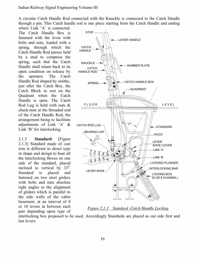
Indian Railway Signal Engineering Volume-III
16
A circular Catch Handle Rod connected with the Knuckle is connected to the Catch Handle through a pin. This Catch handle rod is one piece starting from the Catch Handle and ending where Link ‘A’ is connected. The Catch Handle Box is fastened with the lever with bolts and nuts, loaded with a spring, through which the Catch Handle Rod passes held by a stud to compress the spring, such that the Catch Handle shall return back to its open condition on release by the operator. The Catch Handle Rod shaped by smithy, just after the Catch Box, the Catch Block to rest on the Quadrant when the Catch Handle is open. The Catch Rod Lug is held with nuts & check-nuts at the threaded end of the Catch Handle Rod, the arrangement being to facilitate adjustments of Link ‘A’ & Link ‘B’ for interlocking. 2.1.3 Standard: [Figure 2.1.3] Standard made of cast iron is different to direct type in shape and design to bear all the Interlocking Boxes on one side of the standard, placed inclined to vertical by 330. Standard is placed and fastened on two steel girders with bolts and nuts absolute right angles to the alignment of girders which is parallel to the side walls of the cabin basement, at an interval of 8 or 10 levers in between each pair depending upon type of interlocking box proposed to be used. Accordingly Standards are placed as out side first and last levers.
CATCH
HANDLE
LEVER HANDLE
NUMBER PLATE
STOP
KNUCKLE
CATCH
HANDLE ROD
SPRING CATCH HANDLE BOX
QUADRENT
L E V E LF L O O R
LOCKING BOX
(6 OR 8 CHANNEL)
INTERLOCKING BAR
LOCKING PLUNGER
BEARING CAP
45 8"
6"8"
10"
12"
CATCH ROD LUGSTANDARD
LEVER
SHOE COVER
PIVOT
LINK 'B'
33°
27°
LINK 'A'
LEVER SHOE
Figure 2.1.3 Standard -Catch Handle Locking

17 Pramod P. Goel
The steel girders are rigidly placed on cement concrete Bed Blocks which are placed within the side walls of the cabin basement. Stanchions are provided in between both ends of the girder as and where required for support, depending upon span. The ‘T’ bar runs through on top of all the standards to hold quadrants and also to help the standard maintain it vertical. Brackets for support of four channel locking box are bolted with the front side of the standard and for support of single channel locking box in the rear on space indicated. The Shaft, meant to bear the Lever Shoe runs through all standards end to end and is held in position rigidly by ‘Bearing Cap’ which is fastened at the space provided in the standard as shown in the figure. 2.1.4 Quadrants: Quadrant Left Hand is designed to close space on the left hand side of the first lever while Quadrant Right Hand is designed to close space on right hand side of the last lever. Quadrant Intermediate is used in between all other levers to provide slot for moment of the lever. Catch Block holds the lever in its normal or reverse position as the case may be, held against reed of the Quadrant, when the Catch Handle is open. It shall be possible to move the lever from normal to reverse and vice versa, as and when the Catch Block is lifted above reed of the Quadrant, due to pressing of the Catch Handle against Lever Handle. It is pertinent to note that in case of Catch Handle locking interlocking frame, the Catch Block shall be lifted above reed of the Quadrant only when locking permits so. Two ‘T’ Bars run parallel across all the standards end to end fixed on front and back supports of each Standard. The Quadrants are placed side by side covering space between the Standards, closed by end quadrants on both ends of the lever frame, bolted on both ‘T’ Bars termed as Quadrant Supports. 2.1.5 Lever Shoe: [Figure 2.1.5] Lever Shoe is fastened with the lever through bolts and nuts. Lever shoe cover, the other part, is attached to the Lever Shoe through bolts and nuts encasing the shaft. Unlike Shaft Collars used with direct Interlocking frame, the arrangement to maintain desired space is inbuilt in the Lever Shoe.
Figure 2.1.5
Lever Shoe- Catch Handle locking

Indian Railway Signal Engineering Volume-III
18
Accordingly Left hand Lever Shoe is used on extreme left hand lever, Right Hand Lever Shoe on extreme Right hand lever and Intermediate Lever Shoes are used on all levers other than extreme left and extreme right hand levers to maintain inter lever pitch of 100 mm (4"). 2.1.6 Shaft: Steel Lever shaft of 50 mm diameter runs across and is held rigidly in position at each Standard by Bearing Cap between first Standard to the last of the lever frame. Shaft holds the Lever Shoes for each lever whether spare or in use. Due to regular movement of the levers there is tendency for the shaft to rotate against pressure of the Lever Shoe Cover, due to friction with Lever Shoe which may cause the shaft to have lateral movement and slip out of its resting position on the end Standards. To secure and keep the shaft from moving laterally End
Shaft Cap is provided and secured with bolts in its position on Standards placed on extreme ends. Shaft shall be one piece between any two Standards but may not be single piece across Standard, first to last. 2.1.7 Interlocking Arrangement: Interlocking arrangement comprises of the Locking Boxes to bear Locks of sorts, Interlocking Bars and the Locking Plunger. The Locks are riveted with Interlocking Bars so as to hold or release the locking plunger in conformity to Interlocking Chart. The Locking Plunger in turn holds the Catch Handle from being lifted above Quadrant reeds or releases the Catch Handle there by allowing the Catch Handle being lifted, Catch Block being lifted above reed of the quadrant and consequently lever being operated. A pair of wrought iron Link ‘A’ moves about pivot, provided on both sides of the lever, is attached to Catch Rod Lug, at one end and to the short malleable cast iron Link ‘B’. The other end of the link ‘B’ is connected to the Locking Plunger through pin. The link ‘B’ is sandwiched between both pieces of link ‘A’. The Chanel pitch is 55mm (2-1/16"). See figure 2.1.7 for interlocking arrangements. The figure is in three pieces cut through oblique lines, to accommodate relevant portion to be discussed, from a large size Interlocking Chart taken as example. Vertical parallel strips depict Locking plungers numbered as 8, 9, 10, 11, 15 & 19. Horizontal strips depict channels numbered as CH: ‘C’, CH: ‘D’& CH: ‘E’. Interlocking bars running on the top of the Locking Plunger are depicted through single line by the upper out side of the channel as top interlocking bar-1 and running on the lower side out side of the channel as top Interlocking bar-2. Similarly Interlocking Bar running under the locking plunger shown on the upper side within the channel is interlocking bar-1 and Interlocking Bar running under the locking plunger shown on the lower side within the channel is interlocking bar-2. 2.1.7.1 Locking boxes: Locking Boxes used with Catch handle Locking Interlocking frame are designed for six channels, eight channels and ten channels each of which having eight or ten Tappet Ways to accommodate eight or ten Locking Plungers. The cast iron locking box is machine cut to make Channels and the Tappet Ways to the size to accommodate Interlocking assembly and the Plungers in the form of the Locking Trough. Width of the channel is 40 mm (1-17/32").

19 Pramod P. Goel
MS flat Plunger Guides are bolted on both ends of channel box held by bolts with the side walls of the trough, to hold the Locking Plungers in position. When more than 10 channels are required to be used two or more locking boxes are secured one below the other on two angle irons, one on each side of the locking box, and then whole assembly along with two angle irons, is fixed onto the standard’s brackets.
Figure 2.1.7 Interlocking Chart important features 2.1.7.2 Locking Plunger: The Locking Plunger of dimensions 40.90 mm x 10 mm (1-3/4" x 3/8") has a net stroke of 65 mm (2-15/32"). This stroke is more than the channel pitch of 55mm (2-1/16") as such cutting of notches in the Locking Plunger becomes critical and are required to be done judiciously to avoid conflicting notches. ‘Plunger’ is also mentioned as ‘Tappet’. i) Actuation of the locking Plunger: Actuation of the Locking Plunger is special feature of Catch Handle Interlocking Frame as against Direct Interlocking Frame. As the Catch Handle is pressed against the lever handle, the Catch Rod Lug is lifted if the locking permits so. With the Catch Rod Lug getting lifted, the end of the Link ‘A’ connected to the Lug also gets lifted in turn pressing the other end of the Links about the pivot, to which the Link ‘B’ is connected which in turn imparts forward stroke of 31 mm (1-3/32") to the locking Plunger. As the Lever is moved from normal to reverse position the Locking Plunger first gets another forward stroke of 10 mm (3/8") and thereafter a backwards stroke of 7 mm (9/32") resulting in a net stroke of 3mm, during the lever being put from normal to reverse from press of Catch Handle with start and release of Catch Handle with Completion of the movement. As the catch handle is released the Locking Plunger moves further by 31 mm (1-9/32") resulting in a net

Indian Railway Signal Engineering Volume-III
20
forward stroke to the locking plunger as 65 mm (2-15/32"). The actuation of the Locking Plunger is same but in reversed sequence with the same stroke when lever is put to normal. 2.1.7.3 Locks of sorts & Interlocking: Locks for normal locking are iron cast to the desired shapes and size shall be same as to conform to the channel width. Locks and Slips required for conditional interlocking are specially designed to meet with the given requirement. Conditional Interlocking is also termed as Special Interlocking. The ‘Slip’ a metal plate with two slots parallel to each other is held by two square headed studs screwed onto the Locking Plunger number ‘11’ [Figure 2.1.7] such that the metal plate slides freely between both slots end to end. In such a situation the Lock is designed with an undercut so that it pushes only the slide plate without direct relation with Locking Plunger. Such undercut Lock is depicted with a dotted horizontal line just above the cut. The protruded part of undercut Lock moves in to push the slide imparting idle movement of the lower undercut part of the lock [Figure 2.1.7.3(i)]. Small slip may also work with single square headed stud. Normal Locks such as locks against plunger number ‘9’, ‘15’ and ‘19’ are of full size accordingly the notch is cut in the Locking Plunger to match the shape and size of the Lock. In this example the Interlocking relation is ‘19’ requires ‘15’ when ‘11’ is normal and ‘19’ requires ‘9’ when ‘11’ is reversed. The Slide is cut with half notches on both ends of interlocking face. Two pieces of locks put side by side are used to realise the special interlocking relation. As when the lever ‘19’ is pulled with lever ‘11’ normal, the Undercut Full Lock piece [Figure 2.1.7.3(ii)], with full width protruding and butting against the Slide is pulled (the Interlocking bar being in tension) thereby pushing the Slide which in turn tries to push the undercut lock, which shall not move as the notch in the Lever ‘15’ is not available to accommodate the Lock which is tied with the Undercut Lock through Interlocking Bar (Interlocking bar in this case gets in compression). As the lever ‘19’ is pulled keeping lever ‘11’ normal, after pulling the lever ‘15’ the Lever ‘15’ gets locked in reverse position as the notch in the lever reaches opposite the Lock. The other relation ‘19’ requires ‘9’ when ‘11’ reversed is achieved similarly by pulling lever ‘19’ after levers ‘11’ and ‘9’ having been pulled. It is pertinent to note that there is no relation when the desired condition is not fulfilled such as when lever ‘11’ is normal there is no relation between lever ‘19’ and lever ‘9’, similarly there is no relation between lever ‘19’ and lever ‘15’ when lever ‘11’ is pulled.
Figure 2.1.7.3(i) Undercut
Lock for special locking
Figure 2.1.7.3(ii) Undercut Full
Lock for Special locking
21 Pramod P. Goel
2.1.8.4 Interlocking bars: Mild steel Interlocking Bars are meant to hold the Locks riveted with it, as per requirement depicted in the Interlocking Chart. Each channel of the trough can accommodate two Interlocking Bars under and two at the top of the Locking Plunger, section of each Interlocking Bars being 16 mm x 12 mm (5/8" x 1/2"), the size of the channel at the bottom being 60 mm (1-3/8") is enough to accommodate two Interlocking Bars below the Locking plunger. 2.1.8 Numbering of the channels: As the Locking Boxes are fixed on front of the Lever Frame, channels are numbered from top to bottom when looked at the Interlocking Chart, which in effect means numbers start from first channel of the locking box to the last channel of the last Locking Box. Alphabets are used for numbering channels, staring with ‘A’ in capital only. Accordingly Locking Box channels shall be numbered as ‘A’, ‘B’, ‘C’, ‘D’, ‘E’, ‘F’, ‘G’ & ‘H’. The numbers of the Channels shall continue in same series from ‘I’, ‘J’, ‘K’ and so on, if another Locking box is added to the first one. There is no limit for extension of the channels. The locking plungers are numbered same as that of corresponding levers. 2.1.9 Security of Interlocking against unauthorised interference: The trough is covered by the Cover Plates in style same as that of Direct Locking Interlocking frame and held in position by cotter-bolted and sealed.
*****

Indian Railway Signal Engineering Volume-III
22
CHAPTER- III
TRANSMISSION
3.0 Media of transmission: Under signalling system of single wire the media of transmission between lever and the signal is wire run and for operation of points it is rod run. The wire run is a mix of Galvanised Iron (GI) wire for straight run and wire rope to take diversion on the horizontal/vertical wheels, connected to the Tail of the Lever, to the vertical wheel which is fixed on the Lead-in within cabin and taken out of the cabin to lead Out on Horizontal Rope Wheels and then run up to the signal concerned carried on the pulleys and Horizontal Rope Wheels, passing parallel and across under the railway track to reach up to vertical wheel/wheel mounted near or on the signal post, and attached to the counter weight bar mounted on the signal post. For rod run the rod is connected to the Lever Tail at one end to the arm of Vertical crank mounted on the Lead-in at other end. The next rod is connected to the other arm of the vertical crank, taken out of the cabin and connected to one arm of the Accommodating crank mounted at the out side lead-out. One end of another rod is connected to the other arm of the Accommodating Crank on the out side lead-out. The rod runs further put on Trestles, through rod Compensators, taking diversions in the route through equal arm Horizontal Cranks passing under and across the railway track terminating at the Adjustable Crank to connect the point or Facing point lock or the Lock bar, as the case may be. 3.1 Lead-out: Wire or rod run is connected to the Lever Tail which is at height from the ground floor inside basement to be lead up to ground level and then all such vertical transmissions imparted by the Levers are converted into horizontal transmissions through Vertical Rope wheel in case of wire run and through Vertical Crank in case of rod run. The point falling just below the Lever Tail to convert the vertical transmission into horizontal transmission is termed as ‘Inside Lead-out’. Further more, such converted horizontal transmissions are also to be taken out of the cabin basement to be distributed to either side of the cabin, to be connected the to the Signals, Points, Locks And Lock Bars. At this point of diversion the transmission takes direction on either side of the cabin, right angles to the transmission coming out from the cabin Inside Lead Out. The point at which the diversion and distribution of wire run and the rod run takes place is termed as Outside Lead-out.
Figure 3.1(i) Equipment needed for wire run & inside lead-out

23 Pramod P. Goel
Vertical cranks and wheels may be fixed on i) MS plates or onto ii) Channel iron at the lead-out. i) Lead-out Plates: The plates are chosen of size convenient to be handled by two persons easily. Some railways use 16 mm (5/8") thick plates of the size 1000 mm x 60 mm (3'4" x 2'). Girders are placed spaced at 1000 mm onto which the plates are placed butting each other along the web of the girder and riveted with the girder using 16 mm x 37 mm (5/8" x 1-1/2") cup-headed steel rivets countersunk on top. The girder is fixed on to the cast iron foundation rigidly grouted into the ground with sand, cement and gravel aggregate. Accordingly the connection of rod with vertical crank at the inside lead-out shall be absolute right angles when the arm of the vertical crank to which the rod is connected is absolute vertical.
Maintaining level between inside lead-out and inside lead-out of the foundation plate is of utmost importance to be kept same and horizontal. It shall be ensured that the level of the rod run beyond out side lead out also remains same as that of out side Lead-out. However in case there is any restriction on maintaining the rod run absolutely horizontal, the rod shall be lead forward after getting connected to the Accommodating Crank by making offset in all the rods. If three accommodating cranks are provided on outside lead-out the rod shall be connected to the medium crank straight while the rod connected to the high crank and other to the low crank shall be connected to the high crank and low crank by providing 60 mm (2-1/2") offset upside and low side respectively.
It is pertinent to note that any slope in the rod run shall cause operation of the lever extremely
heavy due to tendency of the rod being sliding downwards or upwards.
ii) Channel Iron Lead-out: Channel Iron is used by some of the railways to fix vertical cranks and vertical rope wheels. These Channel irons are place parallel to the lever frame out side the cabin basement levelled with in side Lead-out and out side wire and rod run with reference to rail level. These Channel irons are fastened firmly with the cast iron foundations which are embedded into ground and grouted with sand, cement and gravel aggregate. While vertical cranks are fixed on the Channel Iron, the horizontal rope wheels are fixed on independent cast iron foundations inside cabin. However outside cabin these horizontal wheels are mounted on Mild Steel plates supported onto the cast iron foundations, to form an array such that the wire run takes off keeping adequate separation to avoid joints entangling with each other while running parallel to the track. It is pertinent to note that any movement of the Inside Lead-out girder or outside lead-out shall
render complete failure of all operations from the cabin concerned which shall be possible only
by non-interlocking the cabin for the period to settle the castings.
3.1.1 Inside Lead-out: Inside lead out is required for leading the wire and the rod run within cabin connecting with the levers and leading out to the outside lead-out.

Indian Railway Signal Engineering Volume-III
24
i) Inside Lead-out for wire run: Two Girders run across the cabin running parallel to the girders which bear the Standards, just below the Lever Tail where the rod for Point, Lock and Lock Bar operation is connected such that the hole in the arm of the Vertical Crank is in exact alignment of the rod hanging free from the lever tail. The rod is connected to the arm of the vertical crank with the arm positioned 100 mm above the level of horizontal line running through the axle of the crank. The Girder ends are fastened with end walls of the cabin basement as well as are firmly held with bolts and nuts with cast iron foundations grouted with sand cement and aggregate into the ground at suitable intervals to ensure that the girders do not allow any movement to the Vertical Cranks. The Vertical Rope wheels are mounted on the Inside Lead-out for wire transmission. Obviously the wire connected to the Lever tail shall not be exactly vertical having been connected at the Lever Tail for greater stroke.
Accordingly a Shackle is connected to Lever Tail hole suitable for desired stroke to the concerned signal. The piece of GI wire is terminated on Thimbles, connected with the Shackle at one end and Wire adjusting Screw at the other end, through Split Links. The other end of the Wire Adjusting Screw is connected to the Wire Rope Sling through Split Link. The wire rope sling passes over Vertical Rope Wheel on Inside Lead-out and connected with the GI wire to be taken out of cabin basement [Figure 3.1.1(i)]. The GI wire is run and connected to the wire rope. This wire rope runs around one way, two way or three way horizontal wheels, as per requirement, fixed on the outside Lead-out to change the direction of wire run. In area provided with 25 KV AC traction all such wires leading in to the cabin basement shall be provided with wire insulators using split links and Thimbles, before the out side lead-out to ensure that the wire touching rails here and there, do not transmit the electric current to the lever frame, harming the operator by the electric shock.

25 Pramod P. Goel
ii) Inside Lead-out for Rod run: Vertical cranks are fixed directly with bolts and nuts on the Channel iron running parallel to the lever frame which is fixed with bolts and nuts with the cast iron Foundations grouted with sand, cement and gravel aggregate, into the ground. In case of the other method by using MS plates, the Channel irons are fixed right angles to the alignment of lever frame leading from inside cabin from the point of inside lead-out to beyond out side cabin up to the point of out side lead-out spaced such that to accommodate the MS plates butting each other along the web of the channel, fastened with bolts and nuts with counter sunk head. The vertical cranks are fixed on the channel iron or the MS plate as the case may be such that the arm of the crank to be connected with down rod hanging from the lever tail, is kept down below the horizontal position by 100 mm so as the arm goes 100 mm above the horizontal position of the arm of the crank to ensure that the movement of the arm of the crank is equal on either side of the horizontal line running across centre of the hub of the crank when operated by the lever for 200 mm stroke. It is pertinent to note that there is no provision fro adjustment in the down rod which is connected to the lever Tail and the arm of the vertical crank through Solid Joints. The down rod shall have no offsets. The other arm of the vertical crank is also connected to the rod through Solid Joint. The solid joint has either butt end or coupling end. In this case the solid joint with coupling end shall be used. Each standard point rod is provided with a coupling joint at its both ends. The rod is connected between the other arm of the Vertical crank and the accommodating crank at the outside lead-out. The rod shall be connected straight to the arm of the Medium crank while an 60 mm (2-1/2") up wards offset shall be given in the rod to connect it with high crank and similar downward offset shall be given to the low crank to match the difference in heights of these cranks at the out side lead-out. The rod inside cabin basement running between inside lead-out and out side lead-out shall be supported onto the Standard Roller Guides which is fastened with the bolts and nuts to the Trestles embedded into the ground rammed properly to ensure no movement. In area provided with 25 KV AC traction all such rods leading out of the cabin basement shall be provided with Rod Insulation, before the out side lead-out, which shall be with butt end or coupling end. It is preferable to provide coupling end Rod Insulation to facilitate replacement in case of damage without going for smithy work. 3.1.1.2 Out side Lead-out: Outside lead-out is to connect the wire and the rod run leading out of the cabin, to be connected with the Signal, Point, Facing point locks and Lock bars. i) Out side Lead-out for wire run: As the GI wire leads out of the cabin basement it is required to be diverted on either side of the cabin using Horizontal wheels further to be connected to the signals concerned running on pulleys which are hung on pulley stakes or gantries. While the space interval (pitch) of 100 mm (4") or 125 mm (5") of the Vertical Rope Wheels depends upon the type of the lever frame used, the Horizontal two way wheels shall be
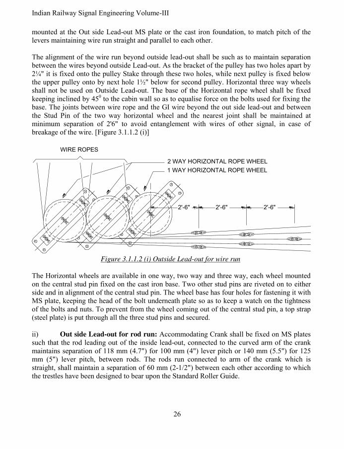
Indian Railway Signal Engineering Volume-III
26
mounted at the Out side Lead-out MS plate or the cast iron foundation, to match pitch of the levers maintaining wire run straight and parallel to each other. The alignment of the wire run beyond outside lead-out shall be such as to maintain separation between the wires beyond outside Lead-out. As the bracket of the pulley has two holes apart by 2¼" it is fixed onto the pulley Stake through these two holes, while next pulley is fixed below the upper pulley onto by next hole 1½" below for second pulley. Horizontal three way wheels shall not be used on Outside Lead-out. The base of the Horizontal rope wheel shall be fixed keeping inclined by 450 to the cabin wall so as to equalise force on the bolts used for fixing the base. The joints between wire rope and the GI wire beyond the out side lead-out and between the Stud Pin of the two way horizontal wheel and the nearest joint shall be maintained at minimum separation of 2'6" to avoid entanglement with wires of other signal, in case of breakage of the wire. [Figure 3.1.1.2 (i)]
The Horizontal wheels are available in one way, two way and three way, each wheel mounted on the central stud pin fixed on the cast iron base. Two other stud pins are riveted on to either side and in alignment of the central stud pin. The wheel base has four holes for fastening it with MS plate, keeping the head of the bolt underneath plate so as to keep a watch on the tightness of the bolts and nuts. To prevent from the wheel coming out of the central stud pin, a top strap (steel plate) is put through all the three stud pins and secured. ii) Out side Lead-out for rod run: Accommodating Crank shall be fixed on MS plates such that the rod leading out of the inside lead-out, connected to the curved arm of the crank maintains separation of 118 mm (4.7") for 100 mm (4") lever pitch or 140 mm (5.5") for 125 mm (5") lever pitch, between rods. The rods run connected to arm of the crank which is straight, shall maintain a separation of 60 mm (2-1/2") between each other according to which the trestles have been designed to bear upon the Standard Roller Guide.
2'-6" 2'-6" 2'-6"
WIRE ROPES
1 WAY HORIZONTAL ROPE WHEEL
2 WAY HORIZONTAL ROPE WHEEL
Figure 3.1.1.2 (i) Outside Lead-out for wire run
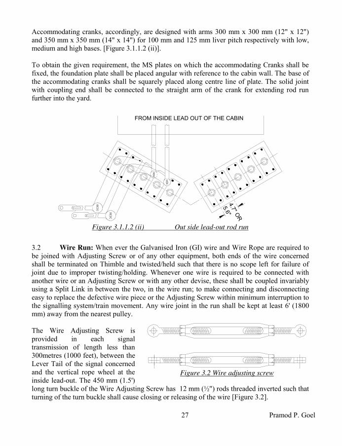
27 Pramod P. Goel
Accommodating cranks, accordingly, are designed with arms 300 mm x 300 mm (12" x 12") and 350 mm x 350 mm (14" x 14") for 100 mm and 125 mm liver pitch respectively with low, medium and high bases. [Figure 3.1.1.2 (ii)]. To obtain the given requirement, the MS plates on which the accommodating Cranks shall be fixed, the foundation plate shall be placed angular with reference to the cabin wall. The base of the accommodating cranks shall be squarely placed along centre line of plate. The solid joint with coupling end shall be connected to the straight arm of the crank for extending rod run further into the yard. 3.2 Wire Run: When ever the Galvanised Iron (GI) wire and Wire Rope are required to be joined with Adjusting Screw or of any other equipment, both ends of the wire concerned shall be terminated on Thimble and twisted/held such that there is no scope left for failure of joint due to improper twisting/holding. Whenever one wire is required to be connected with another wire or an Adjusting Screw or with any other devise, these shall be coupled invariably using a Split Link in between the two, in the wire run; to make connecting and disconnecting easy to replace the defective wire piece or the Adjusting Screw within minimum interruption to the signalling system/train movement. Any wire joint in the run shall be kept at least 6' (1800 mm) away from the nearest pulley. The Wire Adjusting Screw is provided in each signal transmission of length less than 300metres (1000 feet), between the Lever Tail of the signal concerned and the vertical rope wheel at the inside lead-out. The 450 mm (1.5') long turn buckle of the Wire Adjusting Screw has 12 mm (½") rods threaded inverted such that turning of the turn buckle shall cause closing or releasing of the wire [Figure 3.2].
4.7
" OR
5.6
"FROM INSIDE LEAD OUT OF THE CABIN
Figure 3.1.1.2 (ii) Out side lead-out rod run
Figure 3.2 Wire adjusting screw

Indian Railway Signal Engineering Volume-III
28
The wire, after taking off from the lever tail, passing through the inside lead-out and outside lead-out, shall be carried onto the wire pulleys flat or swing, fastened with the pulley stakes, crossing the track as and when needed, passing through point detectors, shall pass through Horizontal Rope Wheel fixed on the signal post such as to impart horizontal run of the wire turned to vertical, terminating at the Counter Weight Lever of the signal concerned. 3.2.1 Wire: Under the single wire system of operation GI wire & Wire rope are used. While GI wire is used for main run and wire rope is used for diversions over the vertical rope wheel and horizontal rope wheel. For normal wire run Galvanised Iron (GI) wire of Standard Wire Gauge (SWG) number 10 which is 3.15 mm (0.128") diameter, is used. This wire being more prone to breakage 7/17 SWG wire of 5 mm diameter (3/16") is used with the advantage of lesser chances breakages, being 7 stranded each strand of 17 SWG, and pre-warning of wire getting weak by breaking of strands, to the maintainer. Galvanised solid steel wire of 5.00 mm (diameter) to IRS specification number S-14 shall be used for detector lever transmission [SEM Part-II, September-2001, paragraph 12.130]. 7 x 7/22 (each rope of seven wires, each wire having seven strands each of 22 SWG, all twisted) with overall diameter being 6 mm (¼") Wire rope is used for diversions in the route of wire run through Horizontal rope wheel and vertical rope wheel owing to its better flexibility. The wire rope used with double wire system of signalling is
with 6 ropes each of 19 strands.
3.2.2 Joining of Wires: Basic principles for joining two wires or the wire and the Adjusting Screw or Signal Slide of the detector shall be i) any two wires or devices in the wire run shall be joined through a split link only. ii) The wire end to be joined shall be wrapped around a thimble to avoid wear and tear due to friction thereby avoiding premature failure of the joint. iii) The split link shall be inserted between the thimbles of two wire ends or the adjusting screw, to be joined. The GI wire end shall be wrapped around thimble with utmost care to avoid cracks in the wire, and then the loose end shall be twisted around the wire to be joined. 7 x 7 wire rope shall be wrapped around the thimble such that the loose end extends by at least 375 mm (15") beyond the tip of the thimble. First strand of the first rope out of seven of the loose end of the wire rope shall be wrapped around the wire rope including the lose end. All the seven strands shall be wrapped tightly followed by second to seventh rope of the wire, making the net finished length of the wire joint as 175 mm (7").
PULLEY STAKE
BRACKET
PULLEY
NUT & BOLT
WIRE PULLEY FLAT
Figure 3.2.3(i) Wire pulley
one way (flat)

29 Pramod P. Goel
3.2.3 Pulley Stakes and Wire Pulleys: The Galvanised Iron wire connected to the Lever Tail at required stroke position, through the Shackle, held with a pin at one end and connected to the rope wire lead out from the cabin at other end, is connected to the Galvanised Iron wire through Thimble and Split Link is carried on the pulleys held onto the pulley-stakes running parallel to the rail track. Right angled Galvanised Iron, steel grade ‘A’, 40 mm x 40 mm x 5 mm of 1220 mm length
Pulley Stakes are driven into ground, absolute vertical and without the pulley stake getting twisted, through pointed tail end cut at an angle of 300. The alignment shall be maintained straight to the extent possible. The pulley stakes are placed at an interval of maximum 10 metres (30') on straight route. Each such Pulley Stake is drilled with holes on its face parallel to the rail track to hold four sets of pulleys one above other. Single or two pulleys are encased and held on a pin to rotate around, into a sheet casing such that it works as wire guide to ensure that the wire born by the pulley does not slip off as well as to be fastened with the pulley stake through bolts and nuts. Wire Pulleys are available as one way flat [figure 3.2.3(i)], two way flat, three way flat and also one way swing, two way swing and three way swing, each encased into a bracket to form a set. The bracket works as wire guide as well as for fixing on the pulley stake with bolts and nuts. Flat pulleys are used on straight wire run. Set of swing pulleys is used on wire run where deviation in the route is encountered [figure 3.2.3 (ii)] as the swing shall adjust itself according to the curvature. In area where deviation in the route takes place the pulley stake shall have an additional force towards centre of curvature of the wire run. Accordingly such pulley stakes shall be grouted in the ground with sand, cement and gravel aggregate for maintaining verticality rigidly. Horizontal rope wheel is used where deviation in the route is more than 300. 3.2.4 Change of Direction of the Wire Run by 30
0 or more: As and where wire run
alignment takes a diversion of 300 or more or has to cross the track at right angles to the track alignment, it shall be on Horizontal Rope Wheels, with three hubs fixed on its base, which in turn is fixed on cast iron foundation embedded into earth and grouted with sand, cement & gravel aggregate to make a rigid base on both sides of the track. The wheels are put on the central hub while two other side hubs may also bear Rope Wheels in between wheels on the central hub, also work as wire guide. Change of direction of wire run shall invariably be through wire rope running on Horizontal Rope Wheel. Horizontal Rope Wheels are available
PULLEY STAKE
BRACKET
PULLEY
NUT & BOLT
PIN
PIN WITH
ROUNDED HEADS
Figure 3.2.3(ii) Wire pulley one
way (swing)

Indian Railway Signal Engineering Volume-III
30
one way, two way and three way to accommodate one wire run on each wheel on the same base [Figure 3.2.4].
3.2.5 Wire run crossing under the track and across Lever crossing: While passing the wire run under the track, the pulley height shall be adjusted such that the wire neither rubs against the rail flange nor it drags upon ground, using smaller size pulley stakes of about 225 to 300 mm (9" to 12") long driven to ground at both sides of the railway track. While passing the wire run
across level crossing gate, a
trench strengthened by plastering with sand and cement is cut across the level crossing road, along the wire run alignment. The trench so prepared is covered by Mild Steel plates to be at the level of the road top. Keeping the MS plates in position over two Channel iron placed opposite each other fixed using nuts and flat headed bolts accommodated into counter sunk holes in the plate maintaining the road surface flat and smooth is another good method. Pulley stakes with pulleys are driven into the ground in either case. This may short circuit both the rails of the track if the section happens to be track circuited. In area electrified with 25 KV AC traction, touching of the wire with the rail flange may turn fatal due to flow of heavy return current. 3.2.6 Wire to detectors: The signal slide shall work right angles to the point slides without any friction. To maintain this, additional pulley stakes may be provided such that the wire at cabin end and at the signal end with the signal slide is absolute straight. This shall be true for all wires running through detectors with signal slide in between. 3.2.7 Termination of wire on signal post: Reaching the wire at the foot of signal post it is connected to the counterweight lever thereby changing the direction of the wire run from horizontal to vertical. One Way Horizontal Rope Wheel is fixed on the concave base clamped with signal base using ‘U’ bolts, used as vertical Rope Wheel, in case of single signal being on the post. Two way Horizontal Rope Wheel may be fixed in case of two signals being mounted on the same post. An uneven right angle 225 mm x 300 mm (9" x 12") arm crank is also used fixed with bolts and nuts, onto the concave base clamped with signal base using ‘U’ bolts in vertical plane, connecting smaller arm with the wire from lever and 300 mm (12") arm with the wire connecting the counterweight balance lever. The 300 mm (12") arm of the crank has three holes at 225 mm (9"), 262 mm (10.5") & last being at 300 mm. This shall help in adjusting/increasing stroke on the counter weight lever depending upon the hole on the larger arm of the crank to which the wire towards counterweight balance lever is connected.
1-12"
1-12"
1-14"
Figure 3.2.4 Horizontal Rope Wheel 3 way

31 Pramod P. Goel
It may be observed that the arrangement of using equal arm crank is superior to the horizontal rope wheel to which the stroke on the counterweight balance lever shall always be same as from lever, while in case of uneven arm crank this can be increased in two steps.
3.2.8 Precautions while laying wire run: First and foremost requirement of an efficient wire run is being friction less, besides prevention against entanglement of the wire joints under normal circumstances as well as in case of wire breakage. Accordingly the wire run shall be sectionalised into straight stretches with minimum diversions. Two pulley stakes each at the point of diversion shall be fixed and the intermediate space shall be filed with equidistant pulley stakes maintaining limit of maximum space of 10 metres between two pulley stakes. The process shall be continued from outside lead-out to the signal post in steps. This shall include the stretch of wire covering point detector. For keeping the friction to the bare minimum, the space between the Horizontal rope wheel and the pulley stake shall be kept to the maximum, avoiding tendency of wire for slipping. Wire put lowest on the pulley stake shall be at least 150 mm (6") clear of the ground and the wire shall be arranged such that the nearer signal dropout first does not cross the transmission wires for farther signals. To avoid entanglement of the wires due to cattle trespassing, the wires shall be placed one above the other with specific reference to the Outer, Warner and advanced starter signals. 3.2.9 Cabin wire adjuster: As the length of transmission increases beyond 300 metres (1000 feet), the expansion of wire due to increased ambient temperature is so much so that desired stroke to take the signal Off does not reach signal resulting in its drooping. To cater for such an eventuality a Cabin Wire Adjuster shall be provided in the cabin. The Wire Adjuster is provided firmly fixed using four bolts and nuts, in the top floor of the cabin near the concerned lever. The wire from the Wire Adjuster is first taken to the Vertical Wheel on Inside Lead-out, taken around the Draft Wheel attached to the Lever Tail beyond; the wire is taken to another paired Vertical Wheel on Inside Lead-out. The wire is further lead to the Out side Lead-out for further outside transmission. Out of type ‘A’ and type ‘B’ the Type ‘B’ Cabin wire adjuster is capable of imparting larger stroke as compared to type ‘A’. The adjustment has to be done critically so as to ensure that the stroke is adjusted limited to maximum ambient temperature while at the same time preventing drooping of the signal when the temperature falls during night even when the signal lever is not pulled. Type ‘A’ Cabin wire adjuster are available with tripping feature. However in this case the wire adjuster is required to be readjusted on each occasion of taking the signal off.
3.3 Rod run: Solid joint with coupling end [Figure 3.3.2 (i)] is connected to the straight arm of the Accommodating crank on the outside lead-out, connected to the rods running further

Indian Railway Signal Engineering Volume-III
32
to be connected to Point, Facing Point Lock and Holding Bar. Rod used are i) tubular and ii) Solid. Usually tubular rods are made to constitute the rod run alignment to keep the run light and as such conveniently operable. However tubular rods shall never be made to join with a solid rod or Solid joint which is made of solid rods only. Full length rod with coupling ends is coupled to the Solid Joint connected with the straight arm of the accommodating crank at the lead-out. The rod is run on standard roller guides to be terminated on the arm of the Adjustable Crank while the other arm of the crank bearing a sleeve is connected to the equipment such as point, Lock Bar etcetera. Roding Compensators are provided as and where required, in between outside Lead-out and the equipment to be operated. The rod run shall be in strict alignment failing which rod rubbing against Standard Roller Guides shall cause effort higher to as required in operation. 3.3.1 Rod: Rods used are tubular and solid. Tubular rods are used for the sake of their light weight. Tubular rod of out side diameter varying between 33.50 mm and 34.50 mm made of mild steel of ‘C’ class tubing of 1" (nominal) bore to BS specifications, with its both ends terminated with coupling end rod made of class ‘1’ steel, are used. The coupling end rod shall be inserted into the tube by not less than 90 mm (3-1/2") and securely welded in position. Owing to failure of joint of the coupling end rod with the tube, leading to hazardous conditions use of tubular
rods has been stopped forthwith. Solid Rod of outside diameter 33 mm (1-1/4") made of class ‘1’ steel weighing not less than 4 lbs/feet are stamped with coupling ends out of the standard length of the rod or the coupling of the diameter same as that of the solid rod is electric flash but welded to both ends of the rod. Both, tubular and solid rods have standard length of 5500 mm (18') including both coupling ends. 3.3.2 Rod joints: Railway signalling system uses standardised joints listed as, i) Eye joints, ii) Joint flush, iii) Joint long, iv) Joint Screw, v) Joint Solid, vi) Joint wide, vii) Point adjusting screw, viii) Lug eye, ix) Swan neck, x) Goose neck, xi) Point rod coupling and xii) Lug eye. Rod joints shall be either with coupling end or butt end. Eye joint is available in 20 mm and 33 mm diameter rods. Eye joint available in 20 mm diameter rod with 55 mm diameter eye, 20 mm diameter or 24 mm diameter hole drilled through centre, at one end is manufactured with butt end. Eye joint of 33 mm diameter rod has 24 mm diameter hole drilled through the eye. Eye joint of 20 mm diameter is used with down rod connecting the counterweight lever to the spectacle.

33 Pramod P. Goel
Joint flush and Long Joint are available in 33 mm diameter rod with butt end and coupling end [Figure 3.3.2(i) for solid joint coupling end].
Maximum used Joint
Solid is available in butt end while coupling end
is used to connect rod with the arm of cranks & compensators.
Joint wide is used when two rods are to be connected onto one and the same arm of the crank or any other such situation.
Point adjusting screw available in coupling end as well as butt end, is used in midst of the throw rod connected between Adjustable crank sleeve and the lug on Engineering Stretcher bar to enable fine adjustments of point setting in conjunction with the adjustment using sleeve of the Adjustable crank [figure 3.3.2 (ii) point adjusting screw & joint screw with coupling end].
JOINT SCREW COUPLING END
POINT ADJUSTING SCREW COUPLING END
Figure 3.3.2 (ii)
Joint Screw is used at the end of the rod terminating on the equipment to be operated such as point indicators, trap indicators, facing Point lock plunger’s fine and critical adjustments. It is available in 20 mm eye with butt end and 33 mm in butt as well as coupling end [figure 3.3.2 (ii)]. This is also used for fine adjustments while connecting the lever lock through lug eye. When another equipment, such as a lever lock, is required to be connected to a rod running through the Lug eye is insert welded in the rod run to operate two equipments by the same lever such as the Facing Point Lock operated by main rod run and Lug Eye connected to the Lever Lock. Though it is available in coupling as well as butt end [figure 3.3.2 (iii)], it shall not be used as Down Rod, when lug eye being connected to the main rod run through coupling end.
SOLID JOINT 33 mm COUPLING END Figure 3.3.2 (i)
Figure 3.3.2 (iii) Lug eye

Indian Railway Signal Engineering Volume-III
34
Connection of the rod to the switch rail is done through Swan Neck or Goose Neck. The Swan Neck shall be used while connecting to the far end Switch rail and Goose Neck while being connected to the near end Switch rail respectively.
Point rod coupling: Coupling end joints of the adjoining rod, couple with each other are designed such that these hold each other firmly while the role of nuts and bolts is limited to keep the joints held together in position, without applying any shearing force on these bolts [figure 3.3.2 (iv)]. 3.3.4 Trestle & Standard Roller Guide: The Rod rests on the bottom roller of the Standard Roller Guide. Top Roller is held in position through a pin driven across the Top Roller’s axis, fastened with the Standard Roller Guide, placed over the rod, using split pins. The Standard Roller Guide is designed to have space to allow rolling of the top roller pin and the bottom roller to cover 8" travel of the rod. The entire assembly shall be erected and maintained to have minimum friction to the rod. 3.3.4.1 Trestle: Trestle, the cast iron base of 380 mm (15") height embedded into ground and rammed properly so as not to allow lateral or sideways tilting, are spaced by 2.2 metres (7') for solid rod and 1.85 metres (6') for tubular rod. 1.85 metres space is maintained in case of curvature in the rod run for solid as well as tubular rods. Two trestles one over the other shall be fastened with each other using bolts and nuts where ground earth is not consolidated enough to withstand forces when the rod is moved by lever or back thrust during movement of train over the trailing points [Figure 3.3.4.2]. Each trestle shall be absolute horizontal as well as absolute vertical and finally also the rod run which shall be checked using spirit level for being perfect horizontal. Undulated rod run shall cause heavy friction while rod level inclined to horizontal shall add to extra effort to work against the weight component of the rod depending upon angle of inclination. Cast iron Trestles are designed to be two-way and four-way. 3.3.4.2 Standard Roller Guide: [Figure 3.3.4.2] Cast iron Standard Roller Guide is fixed onto the trestle top with bolts and nuts with head below and tightened. Head of the bolt is kept below to enable catching attention during inspection of unscrewed bolt and timely tightening.
Figure 3.3.2 (iv) Point rod coupling
TOP ROLLER
SPLIT PIN
RODBOTTOM
ROLLER
96m
m66m
m380m
m
STANDARD
ROLLER
GUIDE
TRESTLE
Figure 3.3.4.2
Trestle and Standard Roller Guide

35 Pramod P. Goel
Bottom roller’s in-built extended axle rests loose on seat of the pair of Standard Roller Guides fastened with the Trestle. The pin bearing the Top Roller is fastened with the pair of Standard Roller Guides after the rod is laid on the bottom roller. It may be noted that for the purpose of taking the rod out of the set of Standard Roller Guides shall be obstructed by the Coupling End of the rod once the top rollers have been fastened. Keeping this in view the joints shall be kept away from any of the Trestle as well as the coupling joint shall be freed of nuts and bolts before taking the rod out of its seat.
3.3.5 Change of Direction of the Rod run: Right angle straight and equal arm crank is used for change in direction of the rod run which shall be at right angle only. Right angle arm crank may be used for i) furthering the direction of transmission onwards and for ii) reversing of direction of transmission on wards. As the rod running from outside lead-out is connected to one arm of the right angle crank for taking a diversion, the rod to the other arm of the crank shall be pushed for a pushing stroke from the lead-out and vice versa [Figure 3.3.5(i)]. However when the crank is placed reversed thereby reversing the direction of push from the outside lead-out to pull and vice versa, such arrangement shall also compensate the expansion and contraction with ambient temperature variations. This compensation shall be equivalent to larger of the incoming or outgoing length of rods.
Straight arm crank with arms at 1800 to each other, are used to offset the route of rod run by 24 inches poised to run further parallel to the incident route. In this case as the incident stroke is reversed to pushing stroke, this also results in compensating the expansion and contraction of the rod with variation in ambient temperature. Relief Crank is used for diverting the route within 200 angle [Figure 3.3.5]. The one arm crank base is fixed on the Cast Iron foundation and when the number of rods is more, on the MS plate fixed on cast iron foundations grouted into ground with sand, cement & gravel aggregate. The crank arm is extended to hold the rod through solid joints one from the out side lead out end and other towards equipment end. 3.3.6 Rod passing under track and level crossing gate: As and when the rod run is required to pass under the track, the rod shall continue to be supported on the trestles and standard roller guides such that i) no trestle shall fall below the rails even at the cost of reduction of inter Trestle distance, ii) only one pair of rods shall pass through across the track
Figure 3.3.5 Relief crank

Indian Railway Signal Engineering Volume-III
36
distributing other than two rods crossing through further spans between the sleepers under the track which shall never be consecutive. As and when the rod run is required to pass through level crossing road, a channel shall be cut across the level crossing road suitable enough to accommodate, all Trestles placed side by side such as to bear all rods required to cross the road. The channels may be constructed strong enough to be able to withstand the road traffic load, plastered with sand cement and covered by MS sheets counter sunk to accommodate flat headed bolts. The other arrangement is providing two channel irons running parallel to each other, placed in the trench so cut to accommodate all the trestles placed side by side, provided with spacer steel tubes in regular interval tightened both the channel irons by bolts and nuts passing through these tubes. The channels shall be covered by Mild Steel sheets and fastened with the flange of the channel using nuts and bots.
3.3.7 Rod compensation: It is the linear elongation and contraction of the Rod in proportion to the variations in ambient temperature calculable based on coefficient of linear expansion for forge iron being 11.3 x 10⁻⁶ metre, per Centigrade or 0.24 inches per 100 yards per 100 F rise of temperature. Accordingly longer the rod run more is the expansion and contraction with increase or decrease of ambient temperature. 200 mm stroke at the lever Tail if reaches, under ideal conditions, at the Adjustable crank connected to the point, is adjusted by the sleeve on the other arm of the crank to impart throw of 125 mm (4½") at the ‘Toe’ of the point. Points are religiously tested with 5 mm obstruction piece placed at 150 mm from the Toe of the switch, in between stock rail and tongue rail and attempting to plunge the facing Point Lock plunger which should not be able to be plunged-in at the same time it should not be possible for the signal slide to move across the point slides. This test is conducted to ensure that the wheel flange is not able to make its way through between tongue rail and the stock rail, resulting in no-road condition and derailment. However a sharp wheel flange may still be able to pierce through between Tongue Rail and Stock Rail derailing the train. Rod Compensators are used to eliminate the conditions of creating gap between the Stock Rail and the Tongue Rail affected by variation in ambient temperature.
Figure 3.3.7(i) Rod Compensator

37 Pramod P. Goel
3.3.7.1 Rod Compensator: It is an assembly of i) cast iron base with four holes and two stud pins, ii) one acute angle crank, ii) one obtuse angle crank and iii) one link to connect the acute angle crank with the one arm of obtuse angle crank. The Rod Compensator base is mounted on the Cast Iron Foundation is fixed using nuts and bolts. The foundation is embedded into ground and concreted with sand, cement & gravel aggregate. The base bearing two Stud Pins, distanced with each other by 545 mm centre to centre, to hold one obtuse angle crank of 1200 and one acute angle crank of 600 connected with each other through a Link. The arm of each crank to which rod is connected shall be 406 mm (16"). The complete assembly is termed as Rod Compensator [Figure 3.3.7(i)]. It may be seen that a pull on one arm of the rod compensator gets translated to push on the other arm thereby absorbing the expansion/contraction of the rod keeping the fixed points viz. lever and the arm of the adjustable crank unaffected by variation in ambient temperature. Such points are termed as neutral points. The other unsolicited affect of the compensator is to reverse the direction of movement of the rod imparted by the lever gets reversed at the equipment side of the compensator while maintaining the lever and the equipment un-effected. The acute angle crank arm shall be connected to the rod coming from the Lever Tail side. It is pertinent to note that the compensator shall function normal within the limiting stroke, beyond which disproportionate variations in the stroke shall take place. The compensator is placed to join the rod aligned normal to the rod run keeping straight with compensator arms placed in or out corresponding to the lever being normal or reversed. Movement of 406 mm arms of the compensator, about the stud pins, is radial resulting in flexing of rod with reference to rod alignment which is maximum when both the arms of the compensator are right angles to the rod alignment. This flexing of rod is away from the line running centre to the rod run alignment. As such, i) undesirable increase of distance of the trestle/standard roller guide nearest to the crank of the compensator shall have to be done to avoid rubbing and jamming of the rod with the Standard Roller Guide. ii) Due to increase flexing the stroke on the rod which shall be one-is-to-one shall become out of proportion. To avoid the undesirable increase of distance of the trestle/standard roller guide nearest to the crank of the compensator, the maximum flexing of the rod to its alignment shall be limited to 15 mm (0.6"). As acute angle crank arm is imparted a stroke extra beyond the normal stroke by 25 mm (1") the other obtuse angle arm shall deflect by 37 mm (1.5") if the acute angle crank arm is imparted another stroke of 25 mm (1") in the same direction the obtuse angle crank arm shall deflect further by 68 mm (2.75"). This erratic behaviour shall create a dangerous condition, if the rod run is meant to operate point causing gap in the point with lever being in normal or reverse position. Accordingly the maximum radial movement of the compensator arms, keeping safety margin, is restricted to 22-1/20 to either side of arm’s mean position.

Indian Railway Signal Engineering Volume-III
38
Accordingly the range of operation of compensator with 406 mm/253 mm/600 acute angle arm & 406 mm/253 mm/1200 obtuse arms vis-à-vis temperature variation range shall be tabulated as 3.3.7.1(ii).
SN Lever stroke at Tail
Range of temperature
Range of transmission
Number of compensators required
1. 6" 150 mm up to 1200 F 1300' 390 m One
2. 6" 150 mm up to 1500 F 1050' 325 m One
3. 6" 150 mm Over 1200 F 1300' 390 m Two
4. 6" 150 mm Over 1500 F 1050' 325 m Two
5. 8" 200 mm up to 1200 F 900' 270 m One
6. 8" 200 mm up to 1500 F 700' 210 m One
7. 8" 200 mm Over 1200 F 900' 270 m Two 8. 8" 200 mm Over 1500 F 700' 210 m Two
Table 3.3.7.1 (ii) Requirement of compensators vis-à-vis length of rod run &
ambient temperature limits.
No compensators shall be required for transmission length up to 12 metre (40') for point and 18.5 m (60') for lock & bar operation. This does not mean that this 12 metre length of the rod shall be ignored in rod run longer than the one in question. The length of rod is measured, for the purpose of working out compensation, from the edge of the cabin wall as the temperature variation within basement is considered negligible. Rod compensation plan shall be prepared before installation of rod run and position of each associated compensator has been marked on the plan. 3.3.7.2 Rod compensation plan: Compensators shall be placed at exact mid way of the total effective length of rod run. If the rod run is absolute straight between outside lead-out and the arm of the crank of operated equipment, the portion of rod between cabin wall and the arm of the Accommodating Crank shall be added to the given length, provided that the Accommodating Crank is used to work normal. In case the Accommodating Crank is working as reversed crank the neutral point shall be shifted away from the accommodating crank by the length of rod run measured between the cabin wall and the accommodating crank. In case of equal arm right angle crank is used for diverting the route by right angles to the main alignment, the length of the rod up to next neutral point shall be added or reduced to the length of rod run depending upon the crank being used as normal or reversed, respectively. In case an unequal arms right angle crank is used in the rod run, the length of rod to be compensated shall be worked out in proportion to the ratio between the two arms of the crank. For example if the arm connected to the rod coming from lever end is 300 mm (12") and other

39 Pramod P. Goel
arm is 150 mm (6"), the ratio of transformation shall be 1: ½ i.e. the 200 mm (8") stroke transmitted at the 200 mm (12") arm of the crank shall be reduced to 100 mm (4") stroke. Accordingly the length of the rod connected to the 150 mm (6") arm shall be doubled as reflected upon original straight rod run for the sake of calculation of effective length of the rod and added or subtracted according to the uneven arm crank being used as normal or reverse, respectively. Similar shall be condition with Right Angle or Straight arm Adjustable crank. As the stroke at the lug of Engineering Stretcher bar is required to be 4½" for setting of points the sleeve of the crank shall be adjusted at 6.75" from the stud pin of the crank. Although in practice the 200 mm (8") stroke at the lever tail reaches reduced at the point because of the wear, tear & play in cranks and compensators the same may reach around 6" (150 mm) at the 300 mm (12") arm of the adjustable crank. In such a situation the sleeve shall be required to be at 9" from the stud pin of the Adjustable Crank to obtain 115 mm (4½") throw on the throw rod. Rod compensation plan shall be prepared based on the principles discussed, for each layout depending upon prevailing conditions. i) Rod Compensation plan Condition (i): [Figure 3.3.7.2(i)] Consider straight part of the 400' rod running out of cabin wall terminates at 300 mm (12") arm of the unequal arm
right angle crank which in turn is connected normal and a 50' rod is connected to the other 150 mm (6") arm. Since the 50' rod is connected to the other arm of the unequal arm crank connected normal the equivalent effective length of the rod should have been 50' but for the arm ratio of the crank being 2:1, it shall be 100'. As such the effective length of the entire rod run shall work out to be 400' + 100' = 500'. Accordingly the Compensator shall be placed at 250' from the cabin wall which is midpoint of the effective length 500'. ii) Rod Compensation plan Condition (ii): [Figure 3.3.7.2(ii)] Consider straight part of the 400' rod running out of cabin wall straight, terminates at 300 mm (12") arm of the equal
arm right angle crank connected reversed and a 100' rod is connected to the other 300 mm (12") arm.
50'
100'400'250'250'
6"
12"
CA
BIN
WA
LL
Figure 3.3.7.2(i) Rod compensation plan condition(i)
100'
100'300'150'150'
CA
BIN
WA
LL
Figure 3.3.7.2(ii) Rod compensation plan
condition(ii)

Indian Railway Signal Engineering Volume-III
40
Since the equal arm crank is connected reversed the 100' rod connected to the other arm of equal arm right angle crank, the same 100' rod shall reflect back to neutralise this part of the rod having been compensated, the effective length of the rod run shall be 400' (-) 100' = 300'. Accordingly the compensator shall be placed at a distance of 150' from the wall of the cabin. iii) Rod Compensation plan Condition (iii): [Figure 3.3.7.2(iii)] Consider the rod run operating one crossover. Accordingly the rod shall be grouped in two parts; first part shall have neutral point at the cabin wall and second neutral point shall be at the arm of first Adjustable Crank for operation of first point. The neutral point of other part of the rod shall be at the arm of the first Adjustable Crank to operate first point of the crossover and on the arm of other Adjustable Crank to operate second point of the crossover. Two compensators ‘C-1’ & ‘C-2’ shall be provided because of having four neutral points in the rod run, two at the cabin and the arm of the first adjustable crank and two at the arm of the first adjustable crank and at the arm of second adjustable crank. Consider total straight rod including both groups being 850' out of which first group being 550' and second being 300'; first throw rod being 30' and second being 14'. Rod running out beyond cabin wall joining at one arm of the Accommodating Crank at the outside lead-out, the rod connected at the other arm of the Accommodating Crank gets terminated at the arm of the rod compensator C-1. The rod runs further one end connected to the other arm of the compensator and other end at the 300 mm (12") arm of the Adjustable Crank placed reversed to the incident rod run, for operating the near end point of the crossover. Another set of rod run connected to the 300 mm (12") arm of the Adjustable Crank using Wide Joint, at the near end point of the crossover and to the 300 mm (12") arm of the Adjustable Crank to operate far end point of the same crossover. It may further be considered that the sleeves of both the adjustable cranks are adjusted at 178 mm (7"). It may be observed that the Adjustable Crank to operate near end point of the crossover is connected reversed so far as the rod run between cabin wall and the near end point is concerned, the same crank is connected normal with reference to the rod run between near end point and far end point of the crossover. However the second Adjustable Crank to operate far end point of the crossover is connected reversed so far as the rod run between both points are considered. Accordingly the total effective length of the rod to provide the Compensator C-1, between cabin and the arm of the Adjustable crank for operating the near end point of the crossover works out to be 14'+550'- 51.4' = 512.6'. Accordingly the central line of the Compensator C-1 shall be positioned at a distance of 242.3' measured from the stud pin of the Accommodating Crank arm at the out side lead out kept right angles and the central line of the compensator. The remaining distance between the central line of the compensator C-1 and the stud pin of the first Adjustable Crank meant for operation of the near end point of the crossover shall workout to be 307.7'.

41 Pramod P. Goel
The total effective length of the rod to provide the Compensator C-2 shall be worked out on the lines same as that of Compensator C-1. Accordingly the effective length of the rod between two adjustable cranks shall workout to be 300' + 51.4' - 24' = 327.4' and so the Compensator shall be placed at mid point of the effective length of the rod being 163.7'. However the distance between two adjustable cranks being 300' the middle line of the Compensator C-2 shall fall at distance of 187.7' from the stud pin of the Adjustable crank for operating far end point of the cross over and 112.3' from the stud pin of the first compensator to operate near end point of the cross over to suit the effective length of the rod.
3.3.8 Termination of rod run: Rod run shall terminate at Adjustable Crank straight arm, connected through solid joint. The sleeve on the other arm of the Adjustable Crank shall be connected to the Lug attached to the Engineering Stretcher Bar of the point, smaller arm of Unequal Arm Crank connected to the Lock Bar, Holding Bar, Fouling Bar and to the Facing Point Lock (FPL) plunger (when the FPL is operated directly without a lock bar in between), through the solid rod with a rod adjusting screw in between. The Adjustable crank (right angle) [Figure 3.3.8(i)] is fixed on cast iron foundation with bolts and nuts. The cast iron foundation is embedded into the ground concreted with sand, cement & gravel aggregate. There is a tendency of movement of the set of points along the set direction of movement of trains especially on double line section, phenomenon called as creep. This in turn results in throw rod connected between the sleeve of Adjustable crank and the point/lock bar/FPL etcetera shall not continue to be right angles to the main rod run thereby
14'
51.4'
550'
256.3'
12" x 12"
12" x 7" 14'12" x 7"
24'
256.3'163.7' 163.7'
300'
C-2
C-1
14'
30'
242.3'
307.7'112.3'
187.7'
Figure 3.3.7.2(iii) Rod compensation plan condition(iii)
Figure 3.3.8(i) Adjustable crank ( right angle)

Indian Railway Signal Engineering Volume-III
42
available force on the point/lock bar/FPL etcetera shall be a smaller component of the main thrust, based on the angle of throw rod with reference to the right angle alignment connection, thereby loosing corresponding element of the force required to operate the equipment. To bring back the original settings the foundation so cast to accommodate the Adjustable Crank has to be either shifted by adding/removing the length of main rod run to the extent of creep so much as to bring the throw rod back to right angle to the main rod run, or preferably a new cast iron foundation be casted and the Adjustable Crank be shifted to this new foundation. Situation may warrant the rod to be terminated on Adjustable straight arm crank [Figure 3.3.8(ii)]. For operation of points, it may be observed that the Adjustable Crank reduces the input stroke of 200 mm into the stroke equal to throw of the point (4-1/2"), using sleeve. Uneven arm crank is used to connect the equipment to be operated after Adjustable Crank such as Lock Bar/Holding
Bar, Facing Point Lock without Lock Bar etcetera [Figure 3.3.8 (iii)] to re-impart 200 mm (8") stroke. As the 300 mm (12") arm of adjustable crank, onto which the rod run from the cabin is terminated, sleeve on the other arm is connected to the throw rod with a screw joint in between. The other end of the throw rod is connected to the smaller 150 mm arm of uneven arm crank. The larger 300 mm (12") arm of the uneven crank is connected to the equipment to be operated such as lock bar or facing point lock if no lock bar is connected to the FPL. It may be appreciated that a facility is there to adjust loss of stroke along the rod run by adjusting position of the sleeve of the Adjustable Crank to provide stroke adjusted such that the same is converted for complete operation of the lock bar/holding bar and the FPL attached with the lock bar or not when connected through uneven arm crank. Accordingly smaller 150 mm of the uneven arm crank is connected with the throw rod, to convert the incoming stroke from the sleeve of Adjusting Crank to Lock bar/ facing point lock without Lock Bar. In totality it is possible by using the set of Adjustable crank, Throw rod and Uneven Arm Crank combined together to provide exact 200 mm stroke to the Lock Bar/ Holding bar or Facing Point Lock without a Lock Bar as the case may be, by adjustment at the sleeve of adjustable crank only.
Figure 3.3.8(ii) Straight arm Adjustable crank
Figure 3.3.8(iii)
Unequal arm crank (right angle)

43 Pramod P. Goel
3.3.9 Process of smith welding at site: Many a times, especially while carrying out maintenance activity the rod may be required to be cut short, elongated by adding a piece, joined to the solid joint or Adjusting screw with butt end or for any other reason has to be done by the black smith, at site. The ends of the rod shall be heated to red hot short of conditions of flowing of the metal using a portable hand operated blower and burning hard coal. The ends of both the rods are tapered, elongated and hammered to join both ends, giving a fine finish without any cracks between the two.
3.3.10 Maximum permissible limits for point operation: Maximum permissible limits for point operation by the lever under single wire system and the Double wire lever used on the lever frame under single wire system:
3.3.10.1 Rod worked points from single wire lever frame operated by single wire lever: Rod worked points operated by lever from cabin may be operated up to the distance: i) Single ended points, with 150 mm (6") stroke at lever tail, within 320 metres (350
yards). ii) Single ended points, with 200 mm (8") stroke at lever tail, within 460 metres (500
yards). iii) Double ended points on running lines with 150 mm (6") stroke, within 180 metres
(195 yards). iv) Double ended points on running lines with 200 mm (8") stroke can be operated up to
275 metres (300 yards). 3.3.10.2 Rod worked points from single wire lever frame operated by Double wire lever: Rod operated points with double wire lever using 500 mm (20") stroke drum may be operated up to the distance: i) 500 metres (550 yards) for points and locks. ii) 1200 metres (1300 yards) for signals without detectors. iii) 600 metres (650 yards) for a single or coupled detector lever transmission. iv) Rod worked single ended points operated by levers with 150 mm (6") stroke, within
320 metres (350 yards) from the cabin.
*****

Indian Railway Signal Engineering Volume-III
44
CHAPTER- IV
SIGNALS
4.0 Signals: Semaphore signals shall be lower quadrant or upper quadrant. Lower quadrant signals are operated by Single wire. Such signals are mounted on lattice or tubular post. Two type of spectacles used are, type ‘A’ and type ‘B’. Signal lamp is used for illuminating the signals during night. The Signal lamp consists of a clear stepped lens at the focal point of which the lamp wick/filament is placed so as to emit a parallel beam of light to enable the Loco Pilot see the signal aspect from a reasonable distance. The clear light as emitted by the lamp is passed through red, yellow or green roundel as fixed onto the spectacle and positioned opposite the Signal Lamp, for the loco Pilot to see the signal aspect. Arm is fastened to the spectacle with bolts and nuts, which shall be square ended or fish tail ended. The arm is enamel painted and is coloured red or yellow with white strip band to enable the Loco Pilot know the type of signal which shall be either running Stop signal or the Warner or Distant signal. As the wire from the Lever Tail running through inside lead-out, out side lead-out, pulleys fixed on pulley stakes, signal slide of the point detector and horizontal wheel fixed onto the signal post, is connected to the Counter Weight Lever, the down rod connected between the Counter Weight Lever and the spectacle is pushed up, to take the signal Off. Provision of Spread light lens is made by providing spherical outer surface on a part of outer stepped lens to spread a part of the focussed beam on horizontal plane to be visible to the loco pilot while travelling on a curve approaching the signal. Subsidiary signals such as Dwarf signal, Calling-on signal, Shunt signal, Point Indicators & trap indicators are also used for controlling and shunting movements of the trains within the Station Section. 4.1 Signal fittings: While signal constitutes of large number of parts, for the Loco Pilot it is spectacle with an arm. The spectacle is mounted on the signal post which may be tubular or lattice, besides many more type of posts, not in use any more. The fittings for the signal are for type ‘A’ Spectacle and type ‘B’ Spectacle. Main parts of the signal are, i) Signal Post, its base, Pinnacle, Ladder & Ladder foundation, ii) Signal dolls 3.6 metres and 2.6 metres, iii) Hook bolt, iv) Purlin, v) Angle stay, vi) Hand rail with deck, vii) Stay, viii) Girder, ix) Channel Post, x) Flange ‘A’ and Flange ‘B’, xi) Semaphore spectacle, xii) Semaphore bracket, xiii) Semaphore Bearing, xiv) Back light screen, xv) Signal Arm, xvi) Stop, xvii) Shock absorber ‘A’ & ‘B’, xviii) Lamp bracket, Lamp bracket carrier and Lamp bracket support, xix) Signal Lamp, xx) Counter weight lever 1 way, 2 way, 3 way and Counter weight support, xxi) Eye joint 20 mm & MS bar 20 mm, xxii) Screw joint 20 mm, xxiii) Wheel clamp, ‘U’ bolt 140 mm diameter tube, horizontal rope wheel 1 way, horizontal rope wheel 2 way, horizontal rope wheel 3 way ‘A’ & ‘B’, xxiv) Rod guide, xxv) Wire shackle, xxviii) Roundels convex, red & green type ‘A’ & ‘B’, xxvi) Clamp 140 mm diameter tube, xxvii) Anchor bolts, xxviii) ‘U’ bolts, xxix) Nuts, Bolts, Washers, Spring washers & Screws.

45 Pramod P. Goel
4.1.1 Signal post Tubular: Tubular signal post is erected on a Cast Iron (CI) base mounted on foundation with its top at rail level or is buried under ground. The post is in two parts upper portion invariably being 5.96 metres (18') in length with outer diameter of 140 mm (5.5"). The post for the lower portion shall cover the balance of the total length of the signal post, with outer diameter being 168 mm (6-5/8"). Thickness of the sheet for both pipes shall be 7.9 mm (5/16"). Both tubes are joined together by inserting the smaller diameter post into the larger diameter post with 460 mm (18") overlap. The lower part which has diameter larger than the other one is pressed hard against the tube of upper part of the post, by swaging process, using swaging tool compressed to the extent to hold the upper tube rigidly in process. Typical over all length of the tubular signal posts is tabulated as 4.1.1. The signal post is inserted onto Cast Iron Signal
Base of a circular table of 512 mm (1'8½") diameter and 41 mm (1-5/8") thickness, with four oblong holes to accommodate the 25 mm (1") diameter foundation anchor bolts, which in turn are fastened with nuts to the bolts of the foundation, casted with sand, cement and gravel aggregate. The circular table and a concentric pipe perpendicular to the base, form a monolithic Cast Iron Base of 550 mm (1'10") height. The pipe of the base is cast tapering gradually downwards from the orifice to allow convenient housing of the 168 mm diameter signal post such that the signal post when inserted into the base, the pipe gets stuck-up at about 50 mm (2") above the bottom of the base. The signal post is plumbed vertical, filled with angular iron wedges between the outer surface of the signal post and inner surface of the pipe of the signal base to hold the post in position rigidly, rest of the space is filled with old rope or some similar material to fill in the empty space. The bitumen is filled to seal the balance space up to a level 50 mm (2") above the orifice of the pipe of the signal base. The Cast Iron signal base may also embedded into ground. 4.1.2 Signal post Lattice: Lattice signal post is available in riveted and welded versions. Four angle irons placed to frame rectangular shape, rising from larger base to narrowing down upwards are kept held rigidly together by iron strips riveted or welded to the angle irons. The tapering is at the rate of 1/8" per foot varying according to the length of the post ending as 175 mm (7"), square as the top of the post. Standard lengths of the post are 6.7 metres, 7.2 metres, 8.2 metres, 9.2 metres, 10.2 metres, 11.2 metres, 12.1 metres & 13.6 metres. The post is held fixed with the anchor bolts casted to the sand, cement and gravel aggregate foundation top of which is kept at rail level, or may be buried in the ground. Batten plates are riveted to the post at an appropriate high position, meant to bear the signal fittings.
SN Post fixed on base at rail level
Post buried under ground
1. 6.7 m (22') 8.2 m (27') 2. 7.2 m (24') 9.2 m (30') 3. 8.2 m (27') 10.2 m (33') 4. 9.2 m (30') 11.2 m (36') 5. 10.2 m (33') 12.2 m (39')
6. 11.2 m (36') 13.2 m (42')
Table 4.1.1 Standard overall lengths of
tubular signal post on base and buried

Indian Railway Signal Engineering Volume-III
46
4.1.3 Bracket Signal Main Posts: While more than one signal such as Outer & Warner can be mounted onto one signal post, two or more signals for more than one diverging or converging routes of the station yard shall be mounted on Dolls the miniature tubular signal posts. Such signal posts shall be i) channel iron post, ii) tubular post or iii) Lattice post. 4.1.3.1 Bracket Signal Posts: Bracket Signal Posts also termed as Dolls, the miniaturised tubular posts of different lengths of outer diameter 140 mm (5.5") and metal thickness being 6 mm, are fixed onto the cross Boom or Gantry to bear the ‘A’ or ‘B’ type signal assembly. Signals for different routes are placed in sequential order corresponding to the route concerned out of which the doll for the signal meant for main line or most important route is kept tallest. Accordingly tubular Dolls are available in 4.9 metres (17.5'), 3.9 metres (14.5'), 2.9 metres (11.5') and 1.9 (8.5') metres lengths. 4.1.3.2 Channel iron Bracket Main Signal Post: Channel iron Bracket Main Signal Post is made by joining two channel irons each of section 8" x 3" x 15 lbs placed opposite each other mounted on to the 21" x 15" x ½" base plate through angle irons and mild steel plates riveted to the channel iron and the base plate. The assembly is reinforced by riveting mild steel plates with the channel irons up to height of 500 mm from the base. Arrangement for Lattice Bracket Main Signal Post is similar to the Channel iron Bracket Main Signal Post.
4.1.3.3 Tubular Bracket Main Signal Post: The tubular Bracket Main Signal Post is in two parts the lower part ‘A’ is of lengths 14.5' or 20' with outside diameter as 10.75", metal thickness being 3/8". The upper part ‘B’ is of 7.5' length with metal thickness of 3/8". Accordingly overall signal post length is kept as 22' and 27.5'. The process of joining two parts shall be same as described in the main signal posts. 4.1.3.4 Boom: Boom, the assembly to bear two or three dolls, the miniature signal posts, is prepared and cross supported using mild steel plates and angle irons riveted to Bracket Main Signal Channel Iron Post. Vertical dimension of the Boom is of 290 mm (11.5") and is fixed rigidly to the Bracket Main Signal Channel Iron Post maintaining minimum space of 5450 mm (17' 10.5") between the bottom of the base plate and lowest portion of the boom, placed onto the channel iron post such that the cross point centre of the boom and the central line along the length of the post coincide with each other, to make the assembly self balanced and stable. A wooden deck board is fitted on the top of the Boom. In case of a two doll arrangement two flanges one above the other are fixed on the boom framework at the centre being 975 mm (3.25") from the centre line of the post on either side onto the boom. The flange ‘A’ is of uniform diameter 143 mm (5-5/8") and flange ‘B’ is of tapered from top as 143 mm (5-5/8") to bottom of the flange as 140 mm (5-3/8") with the result that while the doll post of diameter 143 mm (5-5/8") passes through the flange ‘A’ to flange ‘B’ it is stuck-up at the point above the bottom of flange ‘B’, thus held rigidly fixed in position between two flanges. The post of the doll is tightened in position by bolts provided on the periphery of the flange [Figure 4.1.3.5].

47 Pramod P. Goel
Arrangement for second doll is same as discussed above. The boom is provided with a guard railing to protect workmen from getting out of balance and falling down.
Similar arrangement shall be made to erect and fix Boom onto the Lattice and Tubular
Bracket Signal main Posts. 4.1.3.5 Signal Gantry: When the number of dolls exceeds four, Dolls are fixed onto a signal bridge/ Gantry supported on square based parallel lattice posts, fixed on sand, cement and gravel aggregate foundation through anchor bolts and nuts holding the base plate of the post, at an appropriate height keeping in view Schedule of Dimensions1, ensuring the signals being placed over the corresponding track for clear identification, keeping the doll for the signal meant for main line or most important route as tallest [figure 4.1.3.5].
4.1.4 Pinnacle: Pinnacle is the cap put and fastened on the top of the post to demark its top, prevent unwanted material & rain water to pour into the tube of the post, to cover outer periphery of the tube or lattice post. 4.1.5 Ladder & Ladder
foundation: A ladder made of pair of mild steel flat connected to steps, is erected and clamped with the signal post at 225 mm (9") below the top of the post, supported by stays connected with collars clamped onto the post at suitable intervals so as to ensure that the ladder does not flex under the weight of the person climbing or working on the ladder. A guard rail is provided 1200 mm (4') below the fulcrum of he signal spectacle be it type ‘A’ or ‘B’ to enable the person work conveniently and safely. The end of the ladder is fastened with the cast iron Ladder Foundation, which is firmly embedded into ground.
_______________________________________________________________________ 1Refer Indian Railway Signal Engineering Volume-I, for schedule of dimensions.
RAIL LEVEL
1980 mm
1980 mm
915 mm
FLANGE 'A'
FLANGE 'B'
COUNTER WEIGHT 2500 mm
5450 mm
ROPE WHEEL
CHANNEL 8" X 3" X 15.96 Lbs.
DOWN ROD
Figure 4.1.3.5 Signal Gantry

Indian Railway Signal Engineering Volume-III
48
4.1.6 Semaphore signal fittings: The lower quadrant system of Signalling is two aspect, accordingly the signal assembly mounted on the signal post has two roundels in the Spectacles which are of type ‘A’ and type ‘B’. Accordingly the entire fittings are designed to suit either type of spectacle. The set of fittings are correspondingly termed as fittings type ‘A’ and fittings type ‘B’ respectively. Main parts of the assembly are i) Semaphore Spectacle, ii) Roundels convex, iii) Semaphore Bracket/Bearing, iv) Signal Arm, v) Counter Wight Lever, vi) Stop, vii) Down Rod, viii) Signal Lamp & Lamp bracket and ix) Back Light Screen. 4.1.6.1 Semaphore fittings type ‘A’: As already discussed in preceding paragraph, the Semaphore fittings are almost similar with design different to each other [Figure 4.1.6.1]. i) Semaphore Spectacle: Cast iron
Semaphore Spectacle has circular space to accommodate 213 mm (8-3/8") diameter red and 245 mm (9-5/8") diameter green Roundels fastened with the Spectacle through Roundel Rings fixed on front side of the Spectacle, with screws; respective diameters in the spectacle being 200 mm (7-7/8") & 232 mm (9-1/8"). The centres of the roundels cast 500 angle and 330 mm radius onto the fulcrum. The hole in the spectacle to accommodate the Stud Pin is circular shaped. The signal arm is fixed onto the spectacle with four bolts. The spectacle is mounted on Semaphore Bracket [figure 4.1.6.1(i)]. Roundels are plain coloured glass of thickness same as that of the lens of the Signal Lamp. ii) Semaphore Bracket: Semaphore Brackets are different for tubular and lattice posts. For tubular post, Semaphore Bracket is in two parts Front Clamp & Back Clamp, each having concave surface inside to accommodate 140 mm (5.5") tubular signal post within. Both parts are fastened with each other having the signal post in between and tightened with bolts and nuts. The Front Clamp has a hole on its convex surface onto which 31 mm (1.24") diameter stud pin is riveted to bear the Spectacle which shall work as fulcrum about which the Spectacle revolves. Adjacent to this Stud Pin a projection in casting is
SCREW
JOINT
20mm
380mm
90mm
SEMAPHORE
SPECTACLE
TYPE `A'
GUIDE
DOWN ROD
SEMAPHORE BRACKET
COMPLETE TYPE `A'
600 mm app.
700 mm app.
SEMAPHORE ARM
2 WAY ROPE
WHEEL
HORIZINTAL
WHITE BAND
ON FRONT
WIRE ROPES
PINACLE
PAINTED RED
SEMAPHORE ARMPAINTED YELLOW
Figure 4.1.6.1 Semaphore fittings
2 signals, type ‘A’ on the same post

49 Pramod P. Goel
extended to work as Stop onto which the Spectacle shall rest when normal, to prevent it from cocking (arm lifting upwards). The Back Clamp has two holes into which signal lamp bracket is to be fixed with bolts. For lattice post a rectangular cast iron Bracket is fitted to the post with two bolts into slotted holes. 31 mm (1.24") diameter stud pin is riveted on to the Bracket to bear the Spectacle. iii) Down Rod: Counter Weight Lever is pulled down as the wire connected to it is pulled by the lever in the cabin. The spectacle is made to rotate about the fulcrum by pull of the Down Rod connected at the back of
Spectacle to 20 mm diameter Stud pin which is screwed into 22 mm (7/8") threaded hole into the Spectacle, using 20 mm eye joint. The other end of the Down Rod is connected through adjustable screw held with a pin, on the Counter Weight Lever. The Stud pin is spaced radial by 154 mm (6"), 250 below the horizontal line running from and across the fulcrum respectively. The linear travel of the down rod is 130 mm (5-1/16"). iii) Counter Weight Lever,
Counter Weight & Counter Weight Bracket: Mild steel Straight Lever i.e. Counter Weight Lever is mounted on to a jaw shaped bracket with holes on both parts of the jaw through which the Straight Lever is pinned in between to swing about the pin and resting on either side of the bracket. The Counterweight is mounted on the Counter Weight Lever on the side same on which the Down Rod is connected. The wire is connected to the other end of the fulcrum on the Counter Weight Lever. It may be noted that the Down Rod is connected at the back of ‘A’ type Spectacle.
The Counter Weight is provided to add to the weight of the Spectacle to ensure complete pulling back of the wire run between the cabin and the Counter Weight Lever when the concerned signal lever is put back to normal. A cast iron Circular Weight is held in position at the Counter Weight Lever by bolts screwed into one of the counter sunk grooves, depending upon the distance between signal and the cabin, due to increase/decrease of the return torque. A bolt is tightened through the hole at the end of the lever to which the counterweight is fixed as a safeguard against slippage of the Counter Weight out of lever. Counter Weights are available in 4 kg, 8 kg, 14 kg and 17 kg unit weights. The Counter Weight Lever may be one way, two way or three way accommodated on one and the same bracket depending upon semaphore signals mounted on one and the same signal post.
200 mm
232 mm
184 m
m
495 mm
50
330 mm R
60 mm
FULCRUM
R 154 mm
STUD PIN HOLE
DIAMETERS FOR ROUNDELS ARE
LARGER THAN AS CUT IN SPECTACLE
0
Figure 4.1.6. (i) Semaphore Spectacle type ‘A’

Indian Railway Signal Engineering Volume-III
50
The Counter Weight Bracket to hold the Counter Weight Lever is clamped with ‘U’ bolts directly with its concave surface butting against the tubular post. It may be noted that the Down Rod is connected opposite the side on which wire is connected
and on the side same on which the counterweight is fixed, with reference to the pivot. The
Counter Weight is mounted on the Counter Weight Lever outside down rod.
The Counter Weight Lever is fixed parallel to the track i.e. right angle to the signal arm. iv) Signal Arm: Signal arm is made of 16 SWG thick mild steel sheet enamel painted Signal Red or Golden Yellow colour, to B.S.S. specifications 381G. The Arm shall be fastened with the spectacle using bolts with packing of Lead washers, Felt washers or wooden blocks in between spectacle and the arm. All holes in the arm shall be 14 mm (9/16") diameter which shall be held in position with 12 mm (0.5") diameter bolts. The ‘A1’ type signal arm is square ended, 1220 mm (4') long and 225 mm (10") outer and 178 mm (7") inner broad ends. The red coloured arm is enamel painted with a 178 mm (7") broad white band at 225 mm (10") from the outer end. The back of the arm is white enamel painted with a 178 mm (7") broad black band spaced by 225 mm (10") from the outer end to be just opposite the white band in front. The ‘A2’ type signal arm is 1220 mm (4') long fish tailed enamel painted red or yellow with white on front band parallel to the fish tail edges of dimensions same as those of ‘A1’ type signal arm. Similarly the back of the arm is enamel painted white with black band parallel to the fish tail edges with similar dimensions as on front.
v) Signal Lamp & Lamp Bracket: During night when the visibility of the signal arm is poor to the extent being not visible, the Red light through red roundels when the Stop signal is On and green light when the signal is Off is illuminated for the Loco Pilot to be guided and action taken by him. For this a signal lamp is hooked onto the ‘L’ shaped Lamp Bracket which is fitted with the Back Clamp of Semaphore Bracket in case of tubular signal post. The upper hole is made oblong while the lower is round so as to enable a 50 margin for vertical alignment of the Lamp Bracket when being fixed onto the Back Clamp. The lamp is fixed on the Lamp Tray such that the flame is placed exactly on the focal point of the stepped lens through which the light emitted by the lamp is a focussed parallel clear light beam while passing through the coloured roundel. In case of lattice signal post the lamp bracket is mounted onto the lamp carrier. The kerosene oil lamp is replaced in different sections by an electric lamp powered by the AC supply of State Electricity Board or generated locally by generators, which can be switched on or off by the Station Master. The electric Signal Lamp is also powered by Direct Current (DC) from a battery bank charged by the Solar Panel with a twilight switch to enable automatic switching On and Off the signal lamp with sunset and sunrise respectively. In either case the

51 Pramod P. Goel
filament of the electric lamp shall be placed at the focal point of the stepped lens of the Signal Lamp. vi) Back Light Screen: The signal lamp is provided with a small orifice covered with glass at the back of the signal lamp to enable the cabin man to see if the Signal Lamp is lit to enable him know that the signal is On, as usually the cabin man is placed at the back of the signal. A screen is fixed with the Spectacle to move with it such that the back light shall not be visible to the Cabin Man when the Spectacle is in between 50 range of being normal. It is important to ascertain that the signal arm has gone back to horizontal/normal when the signal lever is put back to normal or is supposed to be normal when used in conjunction with reverser.
4.1.6.2 Semaphore fittings type ‘B’: The details for ‘B’ type Semaphore fittings shall be read with the details of ‘A’ type fittings as discussed in preceding paragraphs, observing variations in design.
i) Semaphore Spectacle: Cast iron Semaphore Spectacle has circular spaces to accommodate 245 mm (9-5/8") diameter red and green Roundels fastened with the Spectacle through Roundel Rings fixed on back side of the Spectacle, with screws; corresponding diameter of both the spectacles being 9-232 mm (1/8"). The centres of the roundels cast 450 angle and 355 mm (14") radial distance from the fulcrum. The hole in the spectacle to accommodate the spindle is square shaped. The signal arm is fixed onto the spectacle with ¼" x 1½" four bolts. The spectacle is mounted on Semaphore Bearing [Figure 4.1.6.2(i)]. ii) Semaphore Bearing: The Semaphore Bearing is in two parts, the cast iron Bearing Clamp and its counter part Clamp used for tubular post. The cast iron Bearing Clamp holds the spindle and is mounted with its concave part butting against the tubular post, using ‘U’ bolts on its upper part while the lower part is bolted with Counter Clamp. Both parts of the Semaphore Bearing are held together with two bolts. The Lamp Bracket is fitted on the counter part of the Clamp using two bolts. The Spectacle is mounted on the spindle of Semaphore Bearing. The spindle is a mild steel cylindrical rod, its two ends protruding out of the Semaphore Bearing on front and back. Portion on front meant to hold the spectacle and back to hold the back light screen, is square and tapered in shape with end threaded such that the Spectacle is fastened rigidly with the
20
2 m
m 232 mm
232 mm
335 mm
R
130 mm275 mm
DIAMENSIONS FOR ROUNDELS ARE
LARGER THAN AS CUT IN SPECTACLE
450
R 118 mm
28 mm
FULCRUM
HOLE FOR SPINDLE
Figure 4.1.6.2(i) Signal fittings type ‘B’

Indian Railway Signal Engineering Volume-III
52
spindle through square hole of the Spectacle meant for the same and tightened with nut, on threaded part of the spindle. Similarly the Back Light Screen having square hole is fixed on the rear part of the spindle tightened with nut on its threaded part. It is unlike Spectacle type ‘A’ where the Spectacle revolves about the Stud pin where as in case of type ‘B’ fittings it is the spindle which rotates along with the Spectacle and back light screen along with the Spectacle. A rectangular cast iron Semaphore Bracket with an arrangement to bear the spindle with two slotted holes is mounted onto the Lattice
post and fixed using bolts.
iii) Signal Lamp & Lamp Bracket:
While the purpose for providing a signal lamp and associated modifications being same as discussed in case of Type ‘A’ fittings, the arrangement for the Lamp Brackets for type ‘B’ fittings are different which being directly bolted to the plate on the lattice post. iv) Stop: The cast iron Stop used for the spectacle type ‘B’ is spring loaded, an independent unit fixed on an independent bracket with ‘U’ bolts on tubular post. Return of the spectacle back to normal of its weight with a thud may break the roundels, which is avoided due to the spring action. There is provision for adjustment of the spring for the stop so as to match the impact. The stop fitted onto a lattice post is called the shock absorber. The spring loaded stop is fixed onto a cast iron rectangular bracket, which in turn is mounted on the signal post using bolts and nuts through slotted holes onto the bracket. The size of the bracket shall be different and match to the dimension of the post for each signal when two signals are placed on the same post. iv) Down Rod: Counter Weight Lever is pulled down as the wire connected to it is pulled by the lever in the cabin. The spectacle is made to rotate about the fulcrum by pull of Down Rod. A 20 mm diameter Stud pin is screwed into 22 mm (7/8") threaded hole at the line passing through the fulcrum bisecting the centre points of red and green roundels, at distance of 118 mm (4½") from the fulcrum, into the Spectacle. One end of the 120 mm (4') circular mild steel Down Rod is connected at the front of Spectacle to hold the Stud pin with the 20 mm (¾") eye joint. The other end of the Down Rod is connected through adjustable screw held with
LEVELRAIL
SEMAPHORE
SPECTACLE
TYPE `B'
HORIZONTAL
WHEEL 1 WAY
PINNACLE
COUNTER WEIGHT
BRACKET & LEVER 1-WAY
SIGNAL ARM
PAINTED RED
DOWN ROD
WIRE ROPE
WHITE BAND
FOUNDATION
COUNTER
WEIGHT
Figure 4.1.6.2 Signal fittings type ‘B’

53 Pramod P. Goel
a pin, at one of the holes on the Counter Weight Lever usually at a distance of 118 mm (4 ½") from the fulcrum of counter weight lever. The linear travel of the down rod is 99.5 mm (3-13/15"). iii) Counter Weight Lever: Besides the principles and design part of the counter weight lever as discussed in preceding paragraph for type ‘A’ fittings of Counterweight lever the variations for type ‘B’ fittings are discussed here. The Counter Weight Lever may be one way, two way or three way accommodated on one and the same bracket depending upon semaphore signals mounted on one and the same signal post. In case of ‘B’ type fittings, the Counter Weight Bracket has flat surface and is fitted on lattice post using counterweight lever support. Fixing the Counter weight bracket on tubular
post, requires special clamp. The Counter Weight Lever is fixed parallel to the signal arm. iv) Signal Arm: Sheet and paint specifications are same for type “B’ Signal arm as that given under ‘A’ type fittings. However dimensions and other details shall be as detailed below: The ‘B1’ type signal arm is square ended, 1070 mm (3.5') long and 245 mm (9-5/8") outer and 178 mm (7") inner broad ends. The red coloured arm is enamel painted with a 178 mm (7") broad white band at 225 mm (10") from the outer end. The back of the arm is white enamel painted with a 178 mm (7") broad black band spaced by 225 mm (10") from the outer end to be just opposite the white band in front. The ‘B2’ type signal arm is 1070 mm (3.5') long fish tailed enamel painted red or yellow with white on front band parallel to the fish tail edges of dimensions same as those of ‘A1’ type signal arm. Similarly the back of the arm is enamel painted white with black band parallel to the fish tail edges with similar dimensions as on front. vi) Back Light Screen: Back Light Screen is directly connected to the signal casting in case of type ‘A’ spectacle and in case of ‘B’ type system the Back Light Screen is fitted with the rear part of the Spindle so as to move with the Spectacle. The purpose of the back light screen is to enable the Cabin Man/Cabin Master view the back light of the signal lamp when the signal is On to ensure that it has been put to On with the lever having been put to normal. The arrangement being high safety involvement banking upon alertness of the Cabin Man.
*****

Indian Railway Signal Engineering Volume-III
54
CHAPTER- V
MONITORING, LOCKING & SAFETY DEVICES
5.0 Monitoring, Locking & Safety Devices: Signalling system warrants three important safety factors viz. i) Correspondence between operating device which is lever in this case and the operated equipment which is the point or the signal, ii) Compliance of the operated equipment to be in conformity to the required norms and, iii) the equipments once operated to the required norms are retained in the last operated position till the train, for which the signal has been taken off, has traversed its route and has reached its destination. 5.1 Correspondences between operating device and the operated equipment &
compliance to required norms: Operating equipment being lever in the cabin, the operated equipment shall be point, crossover, Facing Point Lock with or without a Lock Bar, Holding bar, Fouling or the Clearance Bar, Level Crossing Gate and Boom Lock. As the lever is pulled to operate point, a crossover or a signal, it is not sure that the operated equipment has actually moved. For ensuring correspondence between the lever and the point mechanical or electrical point detector is used. For ensuring correspondence between the lever and the facing point lock, travel of plunger is also verified through mechanical or Electrical Point Detector. For correspondence between lever and signal, Arm & Light Detector is used. However correspondence at level crossing gate is verified by the Gate Man himself personally by inspection. 5.2 Point & Turnout: Refer ‘Indian Railway Signal Engineering Volume IV’ by the author same as that of this book, for structural details of a point. The pair of tongue rails is rigidly held by the Engineering Leading Stretcher Bar with a Lug to which the throw rod is connected between the Adjustable Crank and the Lug, with an adjusting screw between the two so as the to and fro movement of the throw rod moves both the tongue rails together setting evenly. The clearance between the inside edges of tongue rail and the stock rail remains fixed as 125 mm (4 ½") on the side other than to which the point is set. The movement of the points is adjusted for adequate thrust of the tongue rail against the stock rail by adjusting the stroke on Adjustable crank when the lever is set to normal. This thrust shall be equal for setting of point when the lever is reversed. For achieving equal pressure between the tongue rail and the stock rail by using point adjusting screw to reduce the length on one side which shall automatically increase the length for setting on other side thereby reducing and increasing the pressure correspondingly. This setting shall be considered normal. 5.2.1 Crossover: A crossover is a pair of points with rails connecting in between to lead the train from one track to the other. When the crossover is operated by one and the same lever, the connection has to be such that both points move together to set from one track to the other and vice versa.

55 Pramod P. Goel
The adjustment is very critical in this case as if the pressure on one set of points is more then the pressure on other set of points shall get reduced proportionately. As such, first both points of the crossover shall be set with opening equal on either side setting without any pressure against stock rails using screw joints. The points shall be just butting against the stock rail without any pressure adjusted by the sleeve of Adjustable Crank, set on either side. The sleeve of the adjustable crank of the nearer end point shall thereafter be adjusted to put pressure of switch rails against the stock rail, so much so as to be slightly more than required. The sleeve of the adjustable crank of farther end point shall then be adjusted such as to exert pressure against stock rail only so much that the pressure against stock rails of both switch rails is distributed equally, this shall reduce the pressure on the near end point such that the pressure to be equal on near end points and the far end points is same; as well as equal for normal & reverse setting. It is pertinent to note that there shall be one rod compensator between two Adjustable Cranks of a crossover to maintain null points undisturbed due to variation in ambient temperature. Extension pieces are fixed using bolts with head thickness truncated in size such that it does not butt against the bolt fitted to hold the rail with chair on the sleeper, provided by Civil Engineers. Both extension pieces are put between butt end of the split stretcher bar and the tongue rails and tightened with nuts and truncated thickness headed bolts. Solid rods are connected between the Extension Pieces and the point detector slides, with solid joint at point end and nuts with check nuts, on threaded end of the rods. 5.3 Point Detector: Point detector is the device which checks proper setting of points to monitor i) correspondence between the point lever and ii) proper setting of points to be within range. Point detector is housed on a Shoe which is rigidly connected with the flange of the rail running in between two rods connecting the Extension Pieces attached to both tongue rails and point slides in the Detector. Two mild steel angle pieces are fixed onto the top of the Cast iron foundation such that to accommodate the Shoe in between allowing the Shoe to float longitudinally right angles to rail alignment to maintain inter-se status between the shoe and the point slides. See drawing 5.3 showing six way point detector with point slides. The lock slide has not been shown in this drawing. Signal slides, 10 mm thick, run right angles to the point slides. Each signal slide has a notch cut to accommodate the point slide such that it shall not be possible the signal slide to move along the wire run held by the point slide of close
FLANGE ROD
RODS FROM EXTENSION PIECE
SHOE JOINT
SHOE ANGLE SLIDES
POINT SLIDES
SIG
NA
L S
LID
ES
Figure 5.3 Point detector Mechanical

Indian Railway Signal Engineering Volume-III
56
as well as of open switch until the route required by the signal concerned is set. If two signals, out of six given in this example, require the point on which this detector is provided, set normal it shall be possible for the signal slide to move and the signal to be taken Off only when the point is set for the route required by the signals in question. This shall happen by point slide notch coming in alignment of the signal slide when the point is not only set for the signal’s route but also set properly [Figure 5.3(i)]. The open tongue rail connected to the other slide has another wide notch in the slide to allow the signal slide move if the closed switch is set properly. The notch in the point slide of open switch though does not check proper setting of the switch rail but checks setting of the open switch corresponding to the other switch. Accordingly it is kept wide so much that the open switch is detected to ensure movement corresponding to the closed switch and vice versa, failing which serious unsafe conditions may be created. Electric Point Detector may also be used in place of mechanical point detector when the electro mechanical interlocking arrangement is used. The point and Lock slides are connected to the Electric Point Detector which detects complete setting of points normal or reverse. For details refer to Indian Railway Signal Engineering Volume IV, by the same author. 5.3.1 Checking correspondence: it is the closed switch, which is responsible for deciding safe setting of the tongue rail against stock rail and setting of correct direction of the route set for which the point has been operated by the lever in cabin. Signal slides connected in between the wire run for each signal requiring the point to be detected as normal or reverse is encased by a cover to keep the signal slides firmly placed above the point slides. For example, if the signal slide, first from the Shoe joint side, requires the point to be set normal for taking the concerned signal Off, the said signal slide shall be able to cross the point slide only if the notch in the point slide connected to the closed switch set for the route for which the signal is to be taken Off, is in alignment of the signal slide. This shall ensure not only setting of point for correct route as well as proper setting of point with reference to point having been set within permissible limits of relaxed norms of gap between stock rail and the tongue rail ensuring correspondence and proper setting of points. 5.4 Facing point lock: A facing point lock is device to lock the point in last operated condition made of cast iron base and body, a cover plate and a locking plunger with or without detection of travel of plunger. It is of i) Facing Point Lock Plunger Type without detection of travel of plunger, ii) Facing Point Lock Plunger Type with detection of full travel of plunger and iii) Economical Facing Point Lock.
Figure 5.3 (i) Point and lock slide
arrangement

57 Pramod P. Goel
5.4.1 Facing Point Lock without plunger travel detection: A Cast iron case with a pathway cut to accommodate the Locking Plunger and a cover plate to hold the locking plunger in position is fixed on the sleeper with bolts and nuts after the Split Stretcher Bar is fixed on both tongue rails of the point. The Locking Plunger connected to the rod through Adjusting Screw travels to and fro within the path way of the cast iron facing point lock, imparts 200 mm (8") stroke, plunged inside the notch cut in the Split Stretcher bar. This holds the point from moving either way. As and when the point is required to be moved either way, the plunger has to be taken out of the notch in the split stretcher bar by putting the lock lever back to normal. This Facing Point Lock (FPL) does not detect the travel of the plunger and as such has been stopped from being used over the points on which the speed of the train is more than 15 Kmph.
5.4.2 Facing Point Lock with plunger
travel and detection: The 755 mm long 50 mm wide and 19.91 mm thick Lock Plunger above which the 520 mm long lock steel bar of thickness same as that of the plunger, is riveted covering complete width, 120 mm from the edge near to the stretcher bar, of the plunger. Accordingly the net thickness of the plunger and tappet combined together works out to be 39.82 mm [Figure 5.4.2]. Notches open to down side on the split stretcher bar, are of 20 mm deep, 53 mm wide and127 mm (4½") apart centre to centre are cut on Split Stretcher Bar assembly set together, to maintain 1.5 mm clearance on either side of the Lock Plunger [53 -50=3 divided into two]. 1.5 mm clearance is kept for allowable working clearance of 3 mm. As the part projection of 120 mm of the plunger rests in the channel of the FPL base it does not interact with the stretcher bar. It is the Tappet, fixed over the plunger when pushed in, interacts and locks the Stretcher Bar. As the plunger moves in the tappet it enters through the notch and locks the stretcher bar if the notch is in alignment of the tappet.
YY
FPL BASE
ROLLERS
RIVETS
CROSS SLIDE
STRETCHER
GUIDEROLLER
FACING POINT LOCK PLUNGER
FACING POINT LOCK PLUNGER
SPLIT
BAR
FPL COVER
PLATEHOLES FOR
FIXING ON
SLLEPER
NOTCH
Figure 5.4.2 Facing point lock

Indian Railway Signal Engineering Volume-III
58
The Tappet riveted upon Plunger is also designed to work as cam-path for the Cross Slide to travel 32 mm outwards when the plunger travels in, 200 mm stroke through the notch cut in the split stretcher bar holding in position. During travel of the lock the cam path imparts first 87 mm stroke idle to the Cross Slide, for next 57 mm travel of the plunger the stroke to the cross slide is 32 mm, and idle for the remaining 56 mm stroke to the plunger. This 32 mm travel of Cross Slide, to which the lock slide is connected through 33 mm solid rod, imparts 32 mm motion to the lock slide in the Detector. The Facing Point Lock (FPL) is fixed on first sleeper at 500 mm (20") from the running face of the rails/points set for main line, in case of Broad Gauge, rigidly with nuts and 18 mm (¾") diameter bolts keeping head of the bolts at the bottom of the sleeper. The sleeper may be Steel Trough or if the lock is to be fixed on the wooden sleeper or Pre-stressed Reinforced Concrete (PRC) sleeper with the gauge tie plate. The cross slide is put with its lug down wards to hold the rod for connecting the lock slide to the detector. The inside part of the slide holds two rollers held around stud pins screwed with the cross slide base such as to be actuated by the cam path of Tappet riveted to the Facing Pint Lock Plunger. The cross Slide is fixed with the facing pint lock casting using bolts through threaded holes on the top. The Cross slide moves 32 mm right angle to the alignment of the plunger. Accordingly a third slide is added to the point detector which shall have two positions one when the lock plunger is out and other when the lock plunger is in. It shall not be possible to move the signal slide across the point slide even if point is correctly set until the lock slide notch also falls in alignment of the signal slide. This arrangement proves not only the travel of the lock plunger but also that the point is set and locked within permissible limits of clearance in between tongue and stock rails of closed switch. A stretcher bar split into two, loosely coupled together, one end of each is fixed near the toe of both the tongue rails of the point. The base of the cast iron body of the Facing Point Lock is fixed on the sleeper after the split stretcher bar has been fixed with both tongue rails of the point. The cover to hold the locking plunger secured in between the base and cover, is fixed on the cast iron base threaded to accommodate bolts. The point is tested with 5 mm thick obstruction piece kept at a distance of 150 mm (6") from the toe of the tongue rail, between tongue rail and the stock rail and the lock is tried to be plunged-in operated by its lever, it should not be possible to plunge the lock plunger in. If it happens so, the train movement on such point shall not be allowed until repaired. Since it may be possible for the plunger to be in when tested with a 3 mm obstruction piece under similar circumstances, the point slide notch shall be cut accordingly, this being permissible margin of operation but as an extreme condition. The notch in the lock slide of the detector is cut 22 mm (1") to have clearance of 6 mm tolerance on either side of the signal slide to have its friction free movement in case of loss of stroke on lock slide.

59 Pramod P. Goel
Before the advent of Facing Point Lock with detection of the travel of the lock plunger was proved by connecting a lug at the entry end and on the plunger connected to the straight uneven arm right angle crank to drive the lock rod and the lock slide inside Point Detector. With the introduction of the facing point lock with travel of plunger lock detection, the crank arrangement has stood abandoned. 5.4.3 Economical Facing Point Lock: Under system of double wire signalling, the double wire operated point machine has inbuilt rack and pinion to drive the lock plunger with or without a Lock Bar. Similar to the facing point lock with plunger travel detection two tappets are fixed under the Locking plunger which are kept staggered to identify normal and reverse setting of points before locking the point. The unlocking, point setting from one position to other and locking the point set to the other side takes place during single direction movement by a single lever making it economical. Details may be seen in double wire section (Section-II) of this book. 5.5 Stretcher Bar: It is obligatory to lock each tongue rail independently, accordingly the Stretcher Bar is split into two symmetrical components complimentary to each other, each being fastened near the toe of the tongue rail of 33 mm diameter solid rod using the ‘T’ ends. The loose ends of the rod are welded with 18 mm thick, 50 mm wide and 13/16" thick mild steel blades. The Stud riveted on to the Blades of both pieces of the split stretcher bar butt against ‘U’ cuts, are pressed against each other while the split stretcher bars are fixed on both tongue rails. The alignment of the Facing Point Lock shall be exact right angle to the alignment of the Split Stretcher Bar such that the stretcher bar does not rub against the body of the Facing Point Lock. The set of the Split Stretcher Bar, each with its blade, combined together shall rest and pass across the recess of the FPL with the movement of the tongue rails. 1-3/8" thick both pieces of the split stretcher bar move just fit across the recess of the FPL. To maintain 4½" throw of the switch rails, initially 4-5/8" throw of the switch is provided. As leading William’s flexible Stretcher Bar (Engineering Stretcher Bar) placed at 330 mm (13") from the toe of the switch, provides 125 mm (4½") opening at 150 mm (6") from the toe of the switch, the additional throw exerts spring action against stock rail which helps in pressure setting of switch rail against stock rail and pushing the points away from stock rail in case of breakage the throw rod. Proving travel of the plunger ascertains correspondence between lever operation and the
movement of the plunger.
5.6 Correspondence of Signal with lever: As discussed in preceding paragraphs, one of the methods to check correspondence between lever and the signals is viewing the signal arm during day within visibility limits and the signal’s back light during night but only to ascertain replacement back of the signal arm within 50 of Spectacle’s normal position. However for accurate information about position of the signal arm and illumination of the lamp, Arm & light repeaters are used, through electrical means using Circuit controller and

Indian Railway Signal Engineering Volume-III
60
thermostat respectively. For details refer to Indian Railway Signal Engineering Volume-IV, by the author same as that of this book. In area where automatic replacement of the signal back to normal with passage of the train over first track circuit beyond signal is required, a reverser is inserted in between the Down Rod. As the power to the reverser is cut off its slides connected to the down rod give way and the spectacle is thrown back to normal due to gravitational force, the lever still being in pulled position which can be put back to normal on first opportunity. However the Arm and light repeater conveys the status of the lamp light and signal arm On or Off in this case too. 5.7 Lock Bar: The Lock Bar is driven from the end away from the points with help of a horizontal Crank Bar Driving Rod and a Driving Attachment riveted to the Lock Bar.
Uneven sized 50 mm x 37 mm x 6 mm right angle iron of 12810 mm length, chosen to be larger than the largest wheel base of any train to ensure that at least one wheel is on the Lock Bar when a train is standing or moving on the track, is used to keep the point/route locked. For the purpose of carrying it is made in 3 pieces each being of 4270 mm which are joined together with 50 mm x 50 mm x 6 mm mild steel plates fixed on 50 mm face of the lock bar, half of which is riveted at the workshop and other end by using nuts and bolt each at site. The Bar may be fixed inside or out side of the rail, of the track. When fixed inside it is kept down below the rail top under worst conditions of worn out rail top and worn out wheel as the wheel flange is 28.5 mm when new and 35 mm when worn-out. Considering the 3 mm worn-out rail top the lock bar is kept at 38 mm below the rail top with reference to new rail. Lock bar rests on three stops hooked to the flange of the rail. Since the purpose of the lock bar is to detect the wheel and ensuring no operation when any wheel is on the rail within the range of the lock bar, it has to be lifted to feel the wheel if there is any before being operated to other side hanging on lock bar clips. Accordingly twelve Lock Bar Clip bases are hooked onto the rail flange inter clip distance kept as 1220 mm. The Lock Bar Clip is in two parts, i) Bracket and ii) Link also named as Rocker Arm [Figure 5.7(i) Lock bar clip - vertical]. The Bracket is in two parts one Front Clamp to hold the Stud Pin and Jaw and second part is the Back Clamp Jaw to be
Figure 5.7(i) Lock bar clip- vertical

61 Pramod P. Goel
accommodated by rail flange tightened together with a nut and bolt. A Stud Pin is riveted to the Front Clamp to hold the Lock bar clip secured by a washer and a split pin. The other end of the lock bar clip is provided with a pin to hold the Lock Bar 50 mm face. It is pertinent to note that the linear back and forth movement of the Lock Bar shall invariably be radial because of the Lock Bar Clips. Whenever a drive is required to be given to the Facing Point Lock along with the movement of the Lock Bar it shall be supported by the Radial Guide. The Radial Guide is designed such that to give radial lift equal to the lift of the lock bar hung on the Lock Bar Clips resting on either side of the Radial Guide recess with 200 mm throw. An Extended Bracket is accordingly fitted to the Lock Bar on 50 mm face using bolts and nuts. The Extended Bracket is connected to the first or second piece of the lock bar through Flange Connecting Rod using eye joint at the extended bracket and the Driving Attachment at the lock bar, to give strength to the system as well as to ensure integrity of the Lock Bar. The drive is given by the Lock Lever through Adjustable Crank connected to the Uneven Arm Crank through throw rod in between, the other arm of which is connected to the least far end Lock Bar piece through Driving Attachment [Figure 5.7(ii)]. As the Lock Lever is pulled it shall operate adjustable crank, which in turn shall operate the uneven arm crank, operating the Lock Bar moving the Extended Bracket and consequently driving the Lock Driving Rod by 200 mm. With each such movement the Lock Bar shall be lifted hanging on Lock Bar Clips and supported by the Radial Guide, to detect the wheel. If a wheel is detected it shall not be possible to operate the Lock Lever. The Lock Bar Clip is designed for the rocker arm to be leaning by 100 towards rail top to keep the distance between rail top and edge of the 37 mm face of the lock bar to be nearest possible. To ensure continuity, the drive to the Lock Bar is given at the rear end other than to which the function is provided if coupled with the Facing Point Lock. The Bar used as Lock Bar, Holding Bar, Fouling Bar or Clearance Bar etcetera when are required to be provided in the area with the check rail it shall not be possible to provide Lock Bar Clip, there being no space to accommodate them. As such in such a situation a Roller is attached to the 50 mm face of the lock bar, using pin with threaded end tightened to the Lock Bar with nuts, at intervals similar to the fixing schedule for lock bar clips. Roller Path with a semi circular top is fixed to the rail using nut and bolt. As and when drive to the Lock Bar is given from the cabin the lock bar shall lift and move through Roller Path top surface and fall back on other side akin to the movement across Radial Guide. As and when part of the lock bar falls within the area of check rail and part outside, only vertical Lock Bar Clip can be used to be in line with the area of check rail, there being no margin for any lateral movement between the lock bar and the check rail, for that part of the lock bar. The Holding Bar, Clearance Bar and the Fouling bar are used for different purposes to be discussed, are of same shape and size and derive their name based on the function by each of them.
5.7.1 Holding Bar: Usage of the Lock Bar defines its name as and when the Lock Bar is used to hold the route, it is termed as Holding Bar. The Holding Bar is used to hold the route. For this purpose one Holding Bar is provided at a distance of 180 metres from the signal of
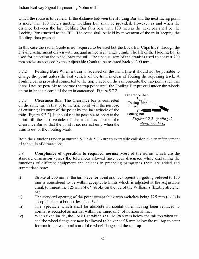
Indian Railway Signal Engineering Volume-III
62
which the route is to be held. If the distance between the Holding Bar and the next facing point is more than 180 meters another Holding Bar shall be provided. However as and when the distance between the last Holding Bar falls less than 180 meters the next bar shall be the Locking Bar attached to the FPL. The route shall be held by movement of the train keeping the Holding Bars pressed. In this case the radial Guide is not required to be used but the Lock Bar Clips lift it through the
Driving Attachment driven with unequal armed right angle crank. The lift of the Holding Bar is used for detecting the wheel over the rail. The unequal arm of the crank is used to convert 200 mm stroke as reduced by the Adjustable Crank to be restored back to 200 mm. 5.7.2 Fouling Bar: When a train is received on the main line it should not be possible to change the point unless the last vehicle of the train is clear of fouling the adjoining track. A Fouling bar is provided connected to the trap placed on the rail opposite the trap point such that it shall not be possible to operate the trap point until the Fouling Bar pressed under the wheels on main line is cleared of the train concerned [Figure 5.7.2]. 5.7.3 Clearance Bar: The Clearance bar is connected on the same rail as that of to the trap point with the purpose of ensuring clearance of the point by the last vehicle of the train [Figure 5.7.2]. It should not be possible to operate the point till the last vehicle of the train has cleared the Clearance Bar so that the point is set normal only when the train is out of the Fouling Mark.
Both the situations under paragraph 5.7.2 & 5.7.3 are to avert side collision due to infringement of schedule of dimensions.
5.8 Compliance of operation to required norms: Most of the norms which are the standard dimension verses the tolerances allowed have been discussed while explaining the functions of different equipment and devices in preceding paragraphs these are added and summarised here: i) Stroke of 200 mm at the tail piece for point and lock operation getting reduced to 150
mm is considered to be within acceptable limits which is adjusted at the Adjustable crank to impart the 125 mm (4½") stroke on the lug of the William’s flexible stretcher bar.
ii) The standard opening of the point except thick web switches being 125 mm (4½") is acceptable up to but not less than 3½".
iii) The Spectacle which shall be absolute horizontal when having been replaced to normal is accepted as normal within the range of 50 of horizontal line.
iv) When fixed inside, the Lock Bar which shall be 28.5 mm below the rail top when rail and the wheel flange are new is allowed to be kept at38 mm below the rail top to cater for maximum wear and tear of the wheel flange and the rail top.
Fouling Mark
{
Fouling bar
Clearance bar
Figure 5.7.2 fouling &
clearance bars

63 Pramod P. Goel
v) The notch in the Split Stretcher bar is cut wider by 3 mm to the exact width of the lock plunger as permissible operational tolerance.
vi) Notch in the Lock slide in the point detector is cut 22 mm (1") which is wider by tolerance of 6 mm (¼") on either side against 10 mm width of the lock slide.
vii) Notch in the point slide is cut 13 mm, wider by 1.5 mm on either side against 10 mm thickness of the signal slide.
viii) Notch in the signal slide is cut 15 mm (5/8") wide as against 12 mm thickness of the point slide.
ix) Inter clip distance kept as 1220 mm for Holding/Lock Bar is approximate which can be readjusted with reference to sleepers placement obstructing fixing of the Lock bar Clip.
x) 53 mm wide notch is cut in the Stretcher Bar provided for Facing Point Lock with detection of travel as against 50 mm width of the lock plunger to maintain a tolerance of 1.5 mm on either side of the plunger.
5.9 Monitoring devices: No chances can be taken with the system of signalling with specific reference to Signals & Points. If the point lever is pulled to take the point to set for reverse but it has not corresponded with the lever, and the signal is taken Off, it shall cause the train to be received on a wrong route. Similarly i) if the lever is pulled to take the signal Off but it does not correspond to the lever, the train shall be kept waiting on the signal concerned keeping the Cabin Master totally ignorant causing undue detention to the train; ii) track occupancy has to be checked before receiving the train on the track concerned; and iii) when the signal is taken Off for reception of the train and the train moves and passes the signal, it shall not be possible to alter the route as set till the train reaches the destination, that is up to the next signal. Accordingly the detector for checking six signal slides, device to check for correct setting of points has been described under the preceding paragraphs and associated drawing numbered 5.3 with finer details shown in drawing numbered 5.3(i). The track vacancy verification by track circuits and the verification of the signal having been taken Off along with illumination of the signal lamp, both subjects have been discussed in Indian railway Signal Engineering Volume-IV by the author same as that of this book, may be referred to. Holding of the route is discussed in following paragraph.
5.10 Holding of the route until train reaches to the destination: Signal lever is last to be pulled for reception or departure of the train to keep the points, locks and Level Crossing Gates locked till the signal lever is put back to normal. Once the signal lever is put back to normal, the facing point lock lever, point lever, level crossing lock lever are rendered free to be operated. Accordingly it may be said that the route is held by the Cabin Master by not putting back the signal lever to normal or that the route is back locked only by the Cabin Master. In case when the automatic replacement of the signal by passage of the train is required, the signal shall be provided with a reverser and a track circuit just ahead of the signal to ensure putting back of the signal to normal by passage of the train, automatically. The Cabin Master is obliged to put the signal lever back in this situation along with automatic replacement of the

Indian Railway Signal Engineering Volume-III
64
signal to normal. Holding Bar is provided at an interval of not more than 180 meters (centre point to centre point) from the signal if the distance between the signal and the first facing point happens to be more than that. This shall be continued till the last facing point is cleared by the train maintaining maximum distance of 180 metres between the signal post and lock bar of the last facing point. This distance is worked out by way of experiments and experience gained by the signal engineers. This arrangement is, back locking the route mechanically. 5.11 Interlocking through Key Plunger Lock & E-Type Locks: So far the subject interlocking and locking of points is concerned the same has been discussed in preceding paragraphs of this book and also in Indian Railway Signal Engineering Volume-I by the author same as that of this book. However with respect to the yard interlocked to standard-I the interlocking and locking of point by key lock is discussed here. Interlocking shall be achieved by Mechanical/Electrical/Electronic means & locking of Point by Facing Point Lock or Point machine, in case of yard Interlocked to Standard-II and requirements being more stringent in case standards-III & IV. However in case of yard Interlocked to Standard-I, the interlocking shall be achieved by mechanical means using E-type lock and by Key Plunger Lock or Facing Point Lock. 5.11.1 Interlocking through Key Plunger Lock: The arrangement of Interlocking between points and signals is used at the stations interlocked to Standard-I, modified non-interlocked or for control of sidings. The system requires i) Key lock Facing Point H.P. Type and ii) ‘E’ type locks. The plunger of ‘E’ type lock which moves in and out of the Box of the Lock by operating key is termed as Lock Bolt. 5.11.2 Key lock Facing Point H.P. Type: Interlocking through Key lock is achieved by using Hand Plunger Lock and E-type Key assembly. The Hand Plunger Lock constituents are i) Lock one way, two way three way or four way, ii) Plunger, iii) handle for the plunger and, E-Type Lock. The cast iron Handle is fixed with nuts & bolts through the hole onto the outer side of the plunger to enable the plunger move in and out by hand. A notch is cut into the plunger to accommodate the Bolt of the E-type lock to keep the Hand Plunger fixed in position till it is kept locked. The cast iron Key Plunger Lock has channels cut to bear the Hand Plunger to move parallel to surface of its base, sliding through the notch cut into the Split Stretcher bar to lock the point in the position. If the points are required to be locked in normal as well as reversed position two lock tappets are riveted onto the Hand Plunger to detect and lock the normal and reversed positions of points. The tappet riveted on the upper surface of the plunger may detect normal setting of points and the one riveted at the dorsal side of the plunger for reversed setting of

65 Pramod P. Goel
points. Notches in the stretcher bar are cut accordingly. The E-type lock is fixed on the bracket (side wing) of the Key Plunger Lock, right angles to the Hand Plunger, using four bolts through the base of the E-type lock running through the threaded holes into the side wing of the Hand Plunger Lock. The cover of the E-type lock is secured by sealing with lead tablets, using braided wire. Key Lock facing Points, Hand plunger type are one way, Double, Treble and Quadruple. 5.11.2.1 Key Lock facing Points, Hand plunger type one way: This arrangement when it is required to keep the facing point locked for any one direction. As and when the route is required to be changed the key is released from the controlling end and used to release the point, change the setting and lock by the Hand Plunger. In this situation the key can not be released from the H.P. Lock there being no corresponding notch in the plunger. This type of key locking is used for controlling intermediate sidings and siding points in station section. 5.11.2.2 Key Lock facing Points, Hand plunger type Double: When the interlocking requires taking the signal Off only when the points are set to the desired position and locked. Under normal conditions when points are free to be operated, i.e. the hand plunger is out of the split stretcher bar, Lock Bolt shall be inside E-type Lock and as such the key shall be locked within. Considering that the point is required to be set to normal position only, it shall be possible to extract key out of the E-type lock only by setting the point in the required position pushing the Hand Plunger in, in alignment with the notch on the Hand Plunger with Bolt of the E-type lock, turning the key to move the Lock Bolt in and extracting the Key out of the E-type lock. This key shall be inserted into the E-type lock mounted on the concerned signal lever, rotate the key to take the Lock Bolt in, releasing the lever concerned to be pulled and take the signal Off. This shall lock the key inside E-type lock fitted on the said lever. It shall keep the point set and locked till the signal is put back to normal and the process is reversed. Two E-type locks shall be used onto the Hand Plunger lock if points are required to be locked in either position meant for two signals for the other route. Fixing the E-Type lock on the Lever in lever frame: The base of the E-type lock is fixed on a Wrought iron bracket through nuts and bolts. The bracket in turn is fixed on the concerned lever using nuts and bolts driven into holes on the lever, drilled for this purpose. When the key is inserted into the E-type lock fixed on the lever, and rotated to take the Lock bolt inside ‘E’ Type lock case and the lever is reversed, bolt of the lock shall be made to rest on the Back Stop fixed on the quadrant so as that it should not be possible to extract the key out of lock till the lever is put back to the normal position. Key Lock facing Points, Hand plunger type Treble & Quadruple are provided with three and four locks to achieve interlocking for more routes lead by the signals. In these cases the points are kept normally free and locked only when the signal is to be taken Off. 5.12 E-Type Key lock: E- type locks are in sizes i) 155 mm x 92 mm and ii) miniaturised size 100 mm x 75 mm.

Indian Railway Signal Engineering Volume-III
66
An E-type lock is constituent of i) Base, Cover, ii) Lock Bolt, iii) Tumblers, three numbers, with associated Tumbler springs, iv) Operating piece and Spring. A key to operate the lock is essential part of each E- type lock. The E- type lock works as an interlocking tool as discussed in preceding paragraphs. These locks are distinguished by 42 combinations of key wards and key lugs [Figure 5.11]. To achieve all these combinations, permutations and combinations of different wards by manipulating three tumblers into different permutations and combinations along with rotation of the lugs one group numbered from 1 to 12, by 450 and second group numbered 13 to 24, by 22 ½ 0 . Such specified locks are identified by their numbers. As a matter of convention such locks used for the purpose of i) hand operated point, ii) Electrical transmission of the key, iii) interlocking of level crossing gate with lever frame, iv) interlocking between point and signal lock numbers are specified. Miniature key locks are used for locking S.M. Slide frame, double wire levers and also the doors of apparatus case. 5.12 Mechanically
operated lifting barriers: Level crossing gates when interlocked are protected by Swing Gates or by Lifting Barriers. In case of swing gates the gate leaves are locked using Key Locks, however when Lifting barrier gates are used, these mechanism consists of i) Winch, ii) Lifting barrier and iii) a combination of Rope Wire/Galvanised Iron wire forming a closed loop on the winch drum and the lifting barrier rope drum. The maximum permissible distance between the Winch and the Lifting barrier is 150 metres.
4241403937 3836
35343331 323029
282725 26242322
2119 2018171615
13 141211109
7
8
65431 2
1.2.3
3.2.2 2.3.31.3.3
1.2.23.1.1
1.1.2 2.2.31.1.33.3.2
2.1.12.2.13.1.2 2.1.3 3.3.1
1.3.22.3.11.2.33.2.1
3.3.1
3.3.2 3.1.1 3.2.2
2.1.12.3.32.2.33.2.11.1.31.1.2
1.3.31.2.21.2.13.1.23.1.32.3.22.1.3
3.2.31.3.12.1.22.3.11.3.23.2.1
Figure 5.12 Lock numbers based on ward and lug
combinations

67 Pramod P. Goel
5.12.1 Winch: Winch meant to give drive to the rope drum of the lifting barriers constitutes i) Post, ii) Pinion ‘A1’ & ‘A2’, two sets, iii) Pinion ‘B1’ & ‘B2’, two sets, iv) Gear Wheel, v) Locking Wheel, vi) Crank Handle, vii) Stopper, and viii) A pair of E-type locks with one and the same number. The crank handle is mounted on the shaft ‘1’ across the Post with Pinion ‘A1’fastened rigidly to it on driving side of the Crank Handle. Pinion ‘B1’ fastened to shaft ‘2’ just below the shaft ‘1’, is intermeshed with Pinion ‘B1’ onto which another pinion ‘A2’ is fastened rigidly butting against the pinion ‘B1’. The Pinion ‘A2’ drives the Gear Wheel, which works as Rope Drum, mounted rigidly on shaft ‘4’ running across the post. The shaft 4 bears Pinion ‘A3’ on the side opposite to the Gear Wheel. Just above this shaft, another shaft ‘3’ housed across the Post between the shaft ‘2’ and Shaft ‘4’ bears the pinion ‘B2’intermeshing with the Pinion ‘A3’. The shaft ‘3’ bears the Locking Wheel rigidly and butting against the Pinion ‘B2’, which is solid cast iron wheel with a cut to accommodate the Bolt of the E-type lock. An ‘E’ type lock is mounted on the Post inverted up side down such that the Bolt of the E-type lock is aligned with the notch on the Locking Wheel which shall occur only when the lifting barrier booms rest on associated stand. As the Crank handle is operated to rotate the Pinion ‘A1’ the corresponding intermeshed pinion ‘B1’ shall also rotate which in turn shall rotate the pinion ‘A2’ being housed on the same shaft as the one bearing pinion ‘A2’. The Gear Wheel shall also rotate as the Pinion ‘A2’ is intermeshed with it. The Gear Wheel shall also rotate the Pinion ‘A3’ along with it for the locking arrangement of the Winch. With the Pinion ‘B2’ intermeshed with the Pinion ‘A3’ the pinion ‘B2’shall also rotate making the Locking wheel also to rotate being on the same shaft. A stop Stud is fixed on the post as well as on the Gear Wheel such that the notch of Locking Wheel is aligned with the Bolt of the E-type lock as and when the both the studs but against each other. As the Bolt of the ‘E’-type lock is aligned against the notch of the Locking Wheel the Key shall be rotated to be extracted from the E-Type lock and inserted into the other E-type lock mounted on the Lock Lever in the laver frame. With the number of the lock being same as that one fitted on the Winch and the one fitted on the Lever, meant to lock the Lifting barrier Booms resting on their stands, reversing the Lock Lever it shall not be possible to release the key and operate the winch. The sequence to open the Lifting barriers for road traffic shall be reverse of what has been discussed above. 5.12.2 Lifting Barrier: While the Winch is meant to operate the lifting Barriers, the lifting barriers are provided to check the road traffic when a train is contemplated to cross the level crossing gate. The lifting barriers are of single barrier or double barriers on both ends of level crossing gate road, depending upon width of the road. Major parts of the Lifting barrier are: i) pair of Pedestals, ii) Boom, iii) Trunnion Bracket and the Drum, iv) Auxiliary Weight and Balancing Weight, v) Boom Stand with Boom Lock.

Indian Railway Signal Engineering Volume-III
68
5.12.3 Pedestal: Pair of cast iron pedestals is fixed with the nuts and bolts, bolts having been grouted into the Cement concrete foundation, a pit to house the extended end of the boom being its integral part. The top of the foundation shall be maintained at the rail level. A pair of brackets is fixed on top of both pedestals with nuts and bolts, to bear the axle about which the Boom shall be rotating up and down. 5.12.4 Boom: Booms used for mechanical Lifting barriers are tubular and are in two sections and two or more parts. The section-I is to be held by the Trunnion Bracket and Section-II is lighter and smaller in diameter joined with the Section-I to make it a continuous body. Tubular poles, which constitute Section-II of the boom are available in 10 metres (30'), 8 metres (24'), 6 metres (18') and 4 metres (12') sizes in one, two or more parts. The length of the boom is cut or added to the size depending upon the width of the road being protected by the Lifting Barrier. Both Booms must be equal in length and weight. Each Boom is painted with black and yellow bands to be distinctively visible to an approaching road vehicle. In addition a circular board painted red inscribed with STOP painted in white letters is also mounted on centre of both the Booms facing approach of the road. The diameter of Section-I of the boom is equal to the inside diameter of the Trunnion Bracket, tapered at the other end to match the diameter of the Section-II boom and extended so as to be joined to the Section-II boom either by welding the two together or by using sockets threaded inside to be joined to threaded socket fixed with the Section-II boom. The boom kept light in design has to be supported by the Stay rods one end of which is fixed onto the stand fixed on the Trunnion bracket. Lugs are fixed on the boom with nuts spaced to hold the threaded end of the Stay rods by nuts tightened on the threaded ends. 5.12.5 Trunnion Bracket: Trunnion Bracket is cast iron body in two parts, upper and lower, to sandwich the Axle passing through the Section-I boom, and sandwich the boom and tightened upper and lower parts together with bolts and nuts. The Boom shall rotate up amd down about this Axle. A pathway is casted in the lower part of the Trunnion Bracket to move the boom up or down by the roller fixed on the Rope Wheel Drum, which while rotating, having been operated by the winch, moves within the pathway of the Trunnion Bracket. The pathway is so designed that lifting and falling of the boom is regulated perfectly and comfortably by the winch. After the boom is erected vertical, the roller shall continue moving coming out of the pathway and rest against the Trunnion Bracket to keep the boom held in erected position as a safety measure to ensure that the boom does not fall on the road traffic of its own or due to mischief. The Rope drum is also provided with steps on its periphery to give lift to the lever connected with a hammer striking against gong and then falling back tipping from step to step, repeating the process till the Boom is closed against road traffic. This arrangement of mechanically
operated warning bell is unique and foolproof.

69 Pramod P. Goel
Similar to mechanically operated bell warning, the road light is also controlled through a bracket attached to the Axle of Trunnion Bracket, thereby converting the vertical movement of the bracket to horizontal and rotating the shaft onto which the Lamp bearing red and white lenses are provided along with corresponding coloured Targets, positioned opposite to each other of the lamp fixed in such a way that as and when the Boom is closed against road traffic the lamp shall display red light to the road traffic and when the Boom is open it shall display white light. 5.12.6 Auxiliary Weight and Balancing Weight: A cast iron bracket in two pieces is fixed around the rear end of the Boom Section-I onto which Auxiliary Weight is put using iron plates, held with nuts and bolts at the flat surface of the Bracket, away from the Axle. These iron plates may be put on top as well as at the bottom of the bracket as many as to make the Boom balanced about the Axle. To make the Boom perfectly balanced cylindrical cast iron pieces, with a hole in the centre of each, are inserted inside from the rear end of the boom Section-I, through a rod held by Axle at one end. The open end of the boom is closed, through which the cylindrical iron pieces were inserted, by a Cover with a hole in its centre, tightened in position by a nut on the rod protruding out of the Cover, thereby securing these cylindrical iron pieces in position. 5.12.7 Boom Stand with Boom Lock: The boom has to rest on the Boom Stand placed at the other end. To keep it secured it has to be locked in resting position. As the Key extracted out of the Winch, after closing the Boom, is inserted into the E-type lock of the Lever meant to lock the boom, and rotated to release the lever from its normal position, it is pulled/reversed to lock the boom by the slide lock inserted into the bracket fitted with the boom. The transmission could be wire or rod, while the wire transmission is no more acceptable because of its poor effectiveness, the rod is made to run using Cranks. A mild steel sheet shaped as Pole Guide is fixed on the top of the Boom Stand to guide and rest the boom down on the specified position to ensure that the lock Slide driven by the Lock lever enters into the bracket fixed on the boom.
Mechanically operated lifting barriers are being replaced with the power operated barriers on
fast pace.
*****

Indian Railway Signal Engineering Volume-III
70
TO
CA
BIN
AD
JU
ST
AB
LE
CR
AN
K
LOCK BAR
RADIAL
GUIDE
LEADING
STRETCHER BAR
1st FOLLOWING
STRETCHER BAR
2nd FOLLOWING
STRETCHER BAR
3rd FOLLOWING
STRETCHER BAR
TO
CA
BIN
AD
JU
ST
AB
LE
CR
AN
K
HORIZONTAL CRANK
Figure 5.7 (ii)
Layout- Facing point- 1 in 16 turnout B.G.

71 Pramod P. Goel
Indian Railway Signal Engineering Volume-III
Section-II
SYSTEM OF MECHANICAL SIGNALLING (DOBLE WIRE)
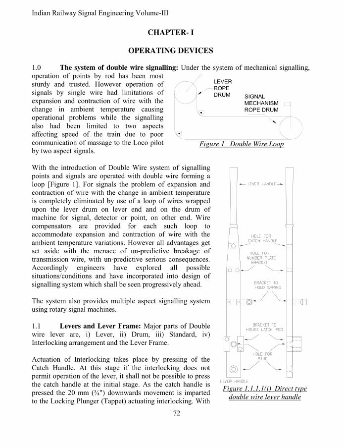
Indian Railway Signal Engineering Volume-III
72
CHAPTER- I
OPERATING DEVICES 1.0 The system of double wire signalling: Under the system of mechanical signalling, operation of points by rod has been most sturdy and trusted. However operation of signals by single wire had limitations of expansion and contraction of wire with the change in ambient temperature causing operational problems while the signalling also had been limited to two aspects affecting speed of the train due to poor communication of massage to the Loco pilot by two aspect signals. With the introduction of Double Wire system of signalling points and signals are operated with double wire forming a loop [Figure 1]. For signals the problem of expansion and contraction of wire with the change in ambient temperature is completely eliminated by use of a loop of wires wrapped upon the lever drum on lever end and on the drum of machine for signal, detector or point, on other end. Wire compensators are provided for each such loop to accommodate expansion and contraction of wire with the ambient temperature variations. However all advantages get set aside with the menace of un-predictive breakage of transmission wire, with un-predictive serious consequences. Accordingly engineers have explored all possible situations/conditions and have incorporated into design of signalling system which shall be seen progressively ahead. The system also provides multiple aspect signalling system using rotary signal machines. 1.1 Levers and Lever Frame: Major parts of Double wire lever are, i) Lever, ii) Drum, iii) Standard, iv) Interlocking arrangement and the Lever Frame. Actuation of Interlocking takes place by pressing of the Catch Handle. At this stage if the interlocking does not permit operation of the lever, it shall not be possible to press the catch handle at the initial stage. As the catch handle is pressed the 20 mm (¾") downwards movement is imparted to the Locking Plunger (Tappet) actuating interlocking. With
LEVER
ROPE
DRUM SIGNAL
MECHANISM
ROPE DRUM
Figure 1 Double Wire Loop
Figure 1.1.1.1(i) Direct type
double wire lever handle

73 Pramod P. Goel
pressing of Catch handle the centre of the arm of the Crank gets positioned in alignment to the centre of the axle of Rope Drum thereby keeping the crank stationary while the lever is operated full. As the lever is reversed moving 1800 about its hub and the Catch handle is released, another 20 mm (¾") movement is imparted to the locking plunger in the direction same as previous one to make it 40 mm (1½"). 1.1.1 Lever: Levers are of types i) Direct, ii) Clutch, iii) Trailable, iv) Rack and Pinion, v) Twin, and vi) Miniature, types. Besides, other levers are Three-to-One, which in effect is a crank for carrying adjustments and Auxiliary Lever to reset a declutched lever. All double wire levers are mounted on a Channel iron onto which the bolts are welded equally spaced such as to accommodate all levers side by side. The arrangement facilitates removal and installation of any lever without disturbing any other one except the interlocking. The interlocking frame is kept opposite to the person operating the levers. 1.1.1.1 Direct type lever: Direct type lever is an assembly of, i) Lever Handle, ii) Rope Drum 500 mm (20") stroke or 600 mm (24") stroke, iii) Catch Handle, iv) Link, v) Latch Rod, vi) Crank, vii) Standard, viii) Catch Handle Spring, ix) Number plate Bracket, x) Main Axle and, xi) Crank Axle Ring. This type of lever is used for working transmission which when broken or obstructed do not create unsafe conditions as such the Direct type levers are used for operating signals which do not have point detector in series of the wire run. When the wire is broken the signal machine shall stop in position with the signal having been thrown back to On if it was already not so. It is pertinent to note that the lever handle and the Rope Drum along with all accessories assembled together make the Lever. i) Lever Handle & Rope Drum: Lever Handle [Figure 1.1.1.1(i)] and Rope Drum [figure 1.1.1.1(v)] are fixed together to move in unison. The Lever Handle moves from normal position to reverse through 1800 imparting 500 mm (20") stroke to the wire loop one pulling and another being pulled. 500 mm stroke works well with distance up to 1200 metres only beyond which 600 mm (24") stroke Rope Drum is used. Two studs with threaded end are welded with the Lever Handle to hold the Rope Drum using hexagonal nuts tightened to the studs rigidly with the Lever Handle. The drum is mounted on the standard across holes between the Rope Drum and the Standard using the stud pin with a bronze bush to provide smooth surface between the Stud Pin and the orifice of the Lever & Standard. This is also required to eliminate wear & tear of the pin by replacing the bush. ii) Lever, Catch handle, Link and Latch Rod: The lever is in two sections, Lever Handle and a flat Mild Steel body. Catch Handle [Figure 1.1.1.1(ii)(b)] is attached to the lever through a hole in the lever, using pin across the catch handle and the lever. Next down below
Figure 1.1.1.1
(ii)(a) Latch rod

Indian Railway Signal Engineering Volume-III
74
the Bracket for number Plate is fixed on two holes made into the lever. A Bracket is fixed with the lever to hold the lower part of the spring connected to the Catch handle, on other end.
Another bracket is provided to house the Latch Rod [Figure 1.1.1.1(ii)(b)] secured under a cover plate. The stud is welded with the lever where two holes are shown to be fixed with the rope drum using nuts on the threaded end of the studs. The catch handle is hinged on the lever with a pin across the catch handle and the lever secured by washer on each end of the pin and split pin. A stop pin is welded to the Catch Handle to ensure its fixed movement as well as to prevent operator’s hand getting pressed in between the Catch handle and the Lever Handle. The Link from out side and the Spring between the space of catch handle are connected to the Catch Handle through a pin across all three. Other end of the Link is connected to the Latch Rod. The latch rod is connected to the arm of the crank at its other end. The ends of the spring terminate on Adjusting Nut & Bolt having an eye joint. Adjusting Nut & Bolt having an eye joint is fastened with the i) Catch handle though the pin across the hole of catch handle and ii) with the bracket fixed on the lever. The spring can be tightened or loosened as per requirement by rotating the nut fastened to the spring around the threaded end of the device attached for the purpose. When the catch handle is pressed, the latch rod is pulled causing the crank to turn about the axle thus imparting stroke to the Tappet. In this way the lever operation is made dependent upon tappet movement and if the tappet is locked under interlocking, it will not be possible to press the catch handle and disengage the Latch Rod Lug from the Quadrant of the Standard. The Link [Figure 1.1.1.(ii)(b)] is a plain Mild Steel strip with eye joint at its both ends one connected to the catch handle and other end connected to the Latch rod. The purpose of the Link is to impart drive to the Crank through the latch rod. The Latch Rod
holds the lever in normal or reverse position through the projected part ‘A’ working as Catch Block. As the latch Rod is lifted up with the pressing of Catch Handle against Lever Handle, it gets out of the quadrant of the Standard thereby permitting movement of the lever to either position. Other action of the Latch rod is to pull the arm of the Crank to actuate the interlocking when catch handle is pressed. The lever is rotated about the Rope Drum’s hub and is released when the lever is completely reversed or normalised.
LINK
SPRING
CATCH HANDLE
STOP PIN
ADJUSTINGNUT & BOLT
ADJUSTINGNUT & BOLT
Figure 1.1.1.1(ii)(b)
Catch handle assembly

75 Pramod P. Goel
The arrangement, as reviewed, is such that as the catch handle is presses against the Lever Handle i) the link gets pulled up and pulls the latch rod which in turn pulls the Crank arm to actuate the interlocking; ii) the spring gets under tension so as to bring the catch handle back to its normal position as and when released, iii) the stud ‘A’ which works as a Catch Block, an integral part of the Latch Rod, gets out of the Quadrant which is a part of the Standard so as to allow the lever to be operated, while simultaneously with the pull to the latch rod, the crank arm comes in alignment with the Rope Drum Axle on which the lever rotates, iv) it becomes possible to rotate the lever if the interlocking permits pressing of the catch handle. iii) Crank: [Figure 1.1.1.1 (iii)] The crank connected to the latch rod eye joint is fixed on the standard through a pin. The pin is held in position by a screw tightened through the quadrant of the standard. As the catch handle is pressed against the Lever Handle, the arm of the crank gets lifted pushing the other arm downwards about the hub. The hole in the arm of the crank connecting the latch rod is made slotted as while the movement of the latch rod is strictly linier the arm of the crank moves about the shaft radially allowing movement of the crank without flexing the latch rod. The crank is held in position on its axle shaft by a 16 SWG silico-manganese steel crank axle ring inserted into the axle shaft groove made for the purpose. iv) Standard and mounting of the Lever: Standard mounted on the Lever frame is the base to house the lever and the Rope Drum such that the handle of the lever is situated at a height comfortable to the Lever Man to hold and reverse it. Hole on the front projection and a slotted hole in the bottom of the base of Standard are made to be tightened with the 5/8" bolts welded to the lever frame. The lever frame is constructed of channel irons. The Rope Drum with a Bronze sleeve within the hole is mounted on the 1¼" diameter axle, secured by ¼" screw, through the right hand part, rope drum and the left hand part of the Standard to reduce friction. The Right hand and left hand directions shall be deemed with reference to the viewer facing the Standard, besides the left hand part of the Standard is shown dotted in figure number 1.1.1.1 (iv), as the rope drum is kept in between the right hand and left hand parts of the Standard. Crank is mounted on the right hand part of the Standard on to which the Quadrant M-N-O also
D.W. LEVER CRANK
LOCKING PLUNGER
CRANK HUB
Figure 1.1.1.1(iii) Crank
N
M
O
ROPE DRUM
AXLE HOLE
CRANK AXLE
HOLE
STANDARD
LEFT HAND PART
HOLES FOR
FIXING STANDARD
QUADRANT
STOPS FOR
RESTING LEVER
Figure 1.1.1.1 (iv) Standard for double
wire system of signalling

Indian Railway Signal Engineering Volume-III
76
has also been casted as its integral part. Accordingly the Latch Rod running through the lever passes over the Right hand part, to be connected to the crank with the stud working as the Catch Block resting against the quadrant. v) Rope Drum: Rope Drum, a circular disk with its rim enough to accommodate Rope Wire, ends fastened firmly, wrapped within the recess of the circular Rope Drum, makes one end of the wire loop the other loop being at signal but without detectors. It is fixed with the lever-studs welded to the lever, tightening nuts to hold the drum rigidly. Drums are available for 550 mm (20") and 600 mm (24") strokes imparted by 1800 rotation of the lever vis-à-vis that of rope drum [Figure 1.1.1.1 (v)]. It is pertinent to note that in case of direct type lever, wire breakage does not affect the interlocking. Whenever, for the sake of safety, if the points get fouled or any such situation arises thereby holding movements of the other equipment imminent, it becomes important to actuate Interlocking, locking the other levers concerned, double wire Clutch type Lever is required to be used. 1.1.1.2 Clutch type lever: Unlike direct type lever where the drum is rigidly fixed with the Lever Handle, the rope drum is attached to the Lever Handle through a spring loaded Clutch, to enable the rope drum disengaged from the Lever as and when conditions so warrant. The Clutch lever is the assembly of i) Lever handle with a Catch handle, ii) Rope Drum, iii) Clutch and associated Spring, iv) Link, v) Latch Rod, vi) Crank, vii) Standard and Main Axle, viii) Crank Axle ring, Locking Plunger (Tappet) and ix) Number Plate bracket with fault indicator. Double Wire Clutch lever is used for operation of Facing Point Locks, Lock Retaining or Holding Bars, Fouling Bars, Detectors and signal transmission with Detectors. A 500 mm stroke lever is used for, i) Points transmission up to 500 metres and ii) Detector transmission up to 600 metres. For point transmission i) greater than 500 metres and up to a maximum of 730 metres and ii) Detector transmission greater than 600 metres and up to maximum of 730 metres, 600 mm stroke lever is employed.
Figure 1.1.1.1(v) Direct type Double wire
rope drum
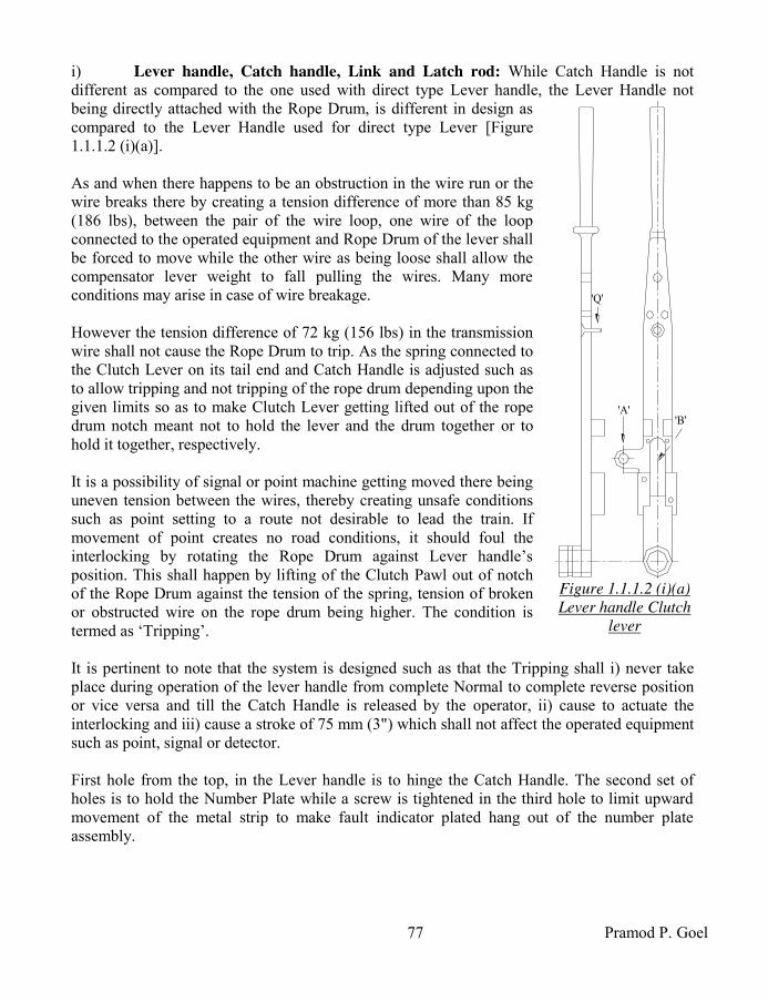
77 Pramod P. Goel
i) Lever handle, Catch handle, Link and Latch rod: While Catch Handle is not different as compared to the one used with direct type Lever handle, the Lever Handle not being directly attached with the Rope Drum, is different in design as compared to the Lever Handle used for direct type Lever [Figure 1.1.1.2 (i)(a)]. As and when there happens to be an obstruction in the wire run or the wire breaks there by creating a tension difference of more than 85 kg (186 lbs), between the pair of the wire loop, one wire of the loop connected to the operated equipment and Rope Drum of the lever shall be forced to move while the other wire as being loose shall allow the compensator lever weight to fall pulling the wires. Many more conditions may arise in case of wire breakage. However the tension difference of 72 kg (156 lbs) in the transmission wire shall not cause the Rope Drum to trip. As the spring connected to the Clutch Lever on its tail end and Catch Handle is adjusted such as to allow tripping and not tripping of the rope drum depending upon the given limits so as to make Clutch Lever getting lifted out of the rope drum notch meant not to hold the lever and the drum together or to hold it together, respectively. It is a possibility of signal or point machine getting moved there being uneven tension between the wires, thereby creating unsafe conditions such as point setting to a route not desirable to lead the train. If movement of point creates no road conditions, it should foul the interlocking by rotating the Rope Drum against Lever handle’s position. This shall happen by lifting of the Clutch Pawl out of notch of the Rope Drum against the tension of the spring, tension of broken or obstructed wire on the rope drum being higher. The condition is termed as ‘Tripping’. It is pertinent to note that the system is designed such as that the Tripping shall i) never take place during operation of the lever handle from complete Normal to complete reverse position or vice versa and till the Catch Handle is released by the operator, ii) cause to actuate the interlocking and iii) cause a stroke of 75 mm (3") which shall not affect the operated equipment such as point, signal or detector. First hole from the top, in the Lever handle is to hinge the Catch Handle. The second set of holes is to hold the Number Plate while a screw is tightened in the third hole to limit upward movement of the metal strip to make fault indicator plated hang out of the number plate assembly.
'B''A'
'Q'
Figure 1.1.1.2 (i)(a)
Lever handle Clutch
lever

Indian Railway Signal Engineering Volume-III
78
Rope drum is mounted on the hollow axle which is an integral part of the Lever Handle [Figure 1.1.1.2 (i)(a)]. The Bronze bush used to minimise friction, inserted into the Lever Handle is mounted on the main axle, which is secured with the Standard by ¼" diameter set screw. The Link rod is connected to the catch handle through eye joint on its both ends along with the adjusting nut and bolt, to hold the spring. The other end of the Link Rod is connected with the Latch Rod [Figure 1.1.1.2(i)(b)]. The Latch Rod is connected at the other end with the Crank, housed and moving encased within the space ‘B’ cut in the Lever Handle, secured by Cover Plate tightened in position with bolts [Figure 1.1.1.2 (i)(a)]. As the catch handle is pressed the Latch rod is lifted up pulling the arm of the Crank making it rotate around its axle and imparting push movement to the locking Plunger (Tappet). ii) Rope Drum, Clutch, Spring and Tripping: Rope Drum [Figure 1.1.12 (ii)(b)] designed to cater for tripping arrangement while simultaneously causing the locking to be fouled, are available in 500 mm (20") and 600 mm (24") strokes. Unlike in case of spring attached between the bracket on the lever and the Catch Handle, in this case the spring is connected between the Catch Handle and tail end of the Clutch Pawl [Figure 1.1.1.2(ii)(a)]. Spring used for double wire Clutch Lever is same as the one shown in drawing for Direct Lever in preceding paragraphs. The Clutch Pawl is hinged on an extended bracket ‘A’ of the Lever Handle, through a pin across the holes, to move about the pin. The nose shaped extended portion of the Clutch Pawl rests into the notch of the Rope Drum while its tail end is connected with the Catch Handle through the Spring. The Spring is adjusted such that the Rope drum does and does not trip depending upon the tension difference between the paired wire loop. As the tension, tangentially along the broken wire, is increased enough to exceed 85 kg (186 lbs), exceeding tension at the nose of the Clutch Lever, the rope drum shall rotate lifting the nose of the Clutch Lever by 2.5 mm, disengaging the drum from the lever and rotating it about its axis by 75 mm (3") measured at the Rope Wire. Accordingly the Rope drum stands Tripped. Keeping in view of the importance of tripping, the Nose of the Clutch Lever is required to be lubricated through Grease Nipple provided at the Nose, to ensure that the Nose does not stick with the Rope Drum at the notch meant to accommodate it. Accordingly the tension difference between the two wires at each such Clutch Lever is adjusted by using Three-To-One lever.
F
P
C
Figure
1.1.1.2(i)(b)
Latch Rod,
Clutch lever
G
Figure 1.1.1.2(ii)(a)
Clutch Pawl
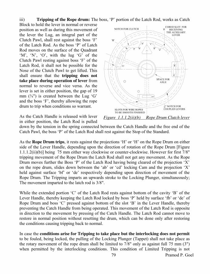
79 Pramod P. Goel
iii) Tripping of the Rope drum: The boss, ‘P’ portion of the Latch Rod, works as Catch Block to hold the lever in normal or reverse position as well as during this movement of the lever the Lug, an integral part of the Clutch Pawl, shall rest against the boss ‘F’ of the Latch Rod. As the boss ‘P’ of Latch Rod moves on the surface of the Quadrant ‘M’, ‘N’, ‘O’, with the lug ‘G’ of the Clutch Pawl resting against boss ‘F’ of the Latch Rod, it shall not be possible for the Nose of the Clutch Pawl to get lifted. This shall ensure that the tripping does not
take place during operation of lever from normal to reverse and vice versa. As the lever is set in either position, the gap of 19 mm (¾") is created between the Lug ‘G’ and the boss ‘F’, thereby allowing the rope drum to trip when conditions so warrant. As the Catch Handle is released with lever in either position, the Latch Rod is pulled down by the tension in the spring connected between the Catch Handle and the free end of the Catch Pawl, the boss ‘P’ of the Latch Rod shall rest against the Stop of the Standard. As the Rope Drum trips, it rests against the projections ‘H’ or ‘H’ on the Rope Drum on either side of the Lever Handle, depending upon the direction of rotation of the Rope Drum [Figure 1.1.1.2(ii)(b)] being 75 mm either way clockwise or counter-clockwise. However for first 7/8" tripping movement of the Rope Drum the Latch Rod shall not get any movement. As the Rope Drum moves further the Boss ‘P’ of the Latch Rod having being cleared of the projection ‘X’ on the rope drum, slides down between the ‘ab’ or ‘cd’ locking Cam and the projection ‘X’ held against surface ‘bf’ or ‘de’ respectively depending upon direction of movement of the Rope Drum. The Tripping imparts an upwards stroke to the Locking Plunger, simultaneously; The movement imparted to the latch rod is 3/8". While the extended portion ‘C’ of the Latch Rod rests against bottom of the cavity ‘B’ of the Lever Handle, thereby keeping the Latch Rod locked by boss ‘P’ held by surface ‘fb’ or ‘de’ of Rope Drum and boss ‘C’ pressed against bottom of the slot ‘B’ in the Lever Handle, thereby preventing the Catch Handle from being operated. This movement of the Latch Rod is opposite in direction to the movement by pressing of the Catch Handle. The Latch Rod cannot move to restore in normal position without resetting the drum, which can be done only after restoring the conditions causing tripping back to normal. In case the conditions arise for Tripping to take place but the interlocking does not permit to be fouled, being locked, the pulling of the Locking Plunger (Tappet) shall not take place as the rotary movement of the rope drum shall be limited to 7/8" only as against full 75 mm (3") when permitted by the interlocking conditions. This condition of Limited Tripping is not
CORED SLOT FORRECEIVING
THE AUXILIARY LEVER
HNOTCH FOR CLUTCH
'H'
E3
E2
716" NOTCH FOR COUPLED LEVERSSLOTS FOR WIRE ROPES
TO BE SMOOTH FINISHED
SPACE FORAXLE
E1
'a'
'b'
'c'
'd''e''f'
Figure 1.1.1.2(ii)(b) Rope Drum Clutch lever

Indian Railway Signal Engineering Volume-III
80
sufficient to transmit stroke for the point to operate being so small as to be absorbed by the double wire compensator.
Resetting of the Rope drum to be de-clutched, the Auxiliary Lever also termed as Clutch Resetting Lever, is used to reset the Rope Drum, inserting into one of the slots E1, E2 or E3, such as to bring the notch below the nose of the Clutch thereby getting the Rope Drum re-engaged with the lever handle, only after the cause of Tripping is attended to. A 500 mm stroke Clutch Lever is used for, i) Points transmission up to 500 metres, and ii) Detectors transmission up to 600 metres, while a 600 mm stroke lever is used for, i) Point transmission beyond 500 metres and up to a maximum of 730 metres, and ii) Detector transmission greater than 600 metres and up to maximum of 730 metres. iv) Standard, Crank, Main Axle and Crank axle: The Standard and the Crank used in Clutch type Lever are same as that used in case of Direct type Lever, discussed in preceding paragraph, while the Rope Drum is mounted on the hollow axle which is the integral part of the Lever Handle. Over all stroke imparted upon the Locking Plunger (tappet) is 40 mm (1½") as discussed in preceding paragraphs. v) Number plate with fault indicator: A number plate is invariably provided on each lever. In case of Clutch Lever while a number plate is fixed on the Lever Handle an indicator is also provided to warn the Lever Man of lever getting Tripped. A mild steel strip connected to the Clutch Pawl by means of a 1/8" pin, runs along the centre of the Lever Handle guided by the pin ‘Q’ on the Laver Handle, to be connected loosely to a Fault Indicator Shaft. As and when the Rope Drum trips the Strip and with it the Fault Indicator Shaft rotates while being pulled down, resulting in display of the Fault Indicator, hanging out of the number plate bracket. vi) Three-to-One
lever: This lever is meant for adjusting the tensions on which the rope drum should or should not Trip. It is pertinent to note that it is not used for operating any equipment and as such is kept outside lever Frame. The length of the lever is such that when inserted in the slot on the Rope Drum of the Clutch Lever it gives mechanical advantage of 3. Accordingly as a force of 85 kg (186 lb), is required to be applied, only 85/3 kg (186/3 = 62 lbs) shall have to be applied and the dynamometer shall read only the 1/3 value of the force applied on to the Rope Drum. Similar is
90°
THREE TO
ONE LEVER
MAIN AXLE
CATCH
HANDLE
SPRING
CATCH
HANDLE
LINK ROD
LATCH
ROD
DYNAMO METER
LEVER HANDLE
Figure 1.1.1.2 (vi) Three to one lever

81 Pramod P. Goel
the case with the force to be applied for lower limit of 72 kg (156 lb) on which the Rope drum shall not be made to trip. The dynamometer is similar to a spring balance. It may be noted that a dynamometer of measuring capacity of 100 lb shall be adequate for the purpose. The Force of 85/3 kg shall be applied as seen on the dynamometer scale and the tension of the spring connected between Clutch Handle and the Clutch Pawl is adjusted by rotating the Nuts and Bolts attached to the Catch Handle Spring, to be fixed at this position to allow the rope drum to trip. Similarly the adjustment shall be done to ensure that the Rope Drum does not trip at 72/3 kg force, as read on the dynamometer [Figure 1.1.1.2(vi)]. vii) Affect of tripping on Interlocking arrangements: The Rope Drum may trip either way when the Lever is set to normal or to reverse. The tripping of the Rope Drum shall invariably actuate the locking plunger except when the Locking Plunger (Tappet) is locked within interlocking frame by some other lever, as discussed in preceding paragraph. The
movement of the Locking Plunger (Tappet) due to tripping of lever shall be in the direction in
which the tappet moved last. For example if the Catch Handle is released when the lever is put to normal from its reversed position, the movement of the Locking Plunger shall be upwards i.e. in the direction of coming out of the locking frame. Now as and when the Rope Drum trips when lever is set to normal, the movement of the Locking Plunger shall be upwards i.e. in the direction of coming out of the locking frame which happens to be the direction same as that of last operation of the Locking Plunger. Notch in the locking plunger shall be cut tight if tripping is intended to foul the locking, however if tripping is not intended to foul the interlocking the length of the notch shall be cut elongated equal to the movement of the locking plunger due to tripping, so as not to actuate interlocking by the movement of the locking Plunger due to tripping of the Rope Drum. 1.1.1.3 Rack & pinion Lever: Operation of points with double wire especially not detected with double wire detector is not found to be safe in case of breakage of wire operating point. Accordingly Point, Facing Point Lock with or without Lock Bar as used under Single wire system of signalling, discussed under preceding chapters, are operated by 33 mm diameter mild steel rods is used under double wire system of signalling also operated by Rack & pinion lever. Major parts of the Rack & Pinion lever are, i) Rack & Pinion with a Roller [Figure 1.1.1.3(i)], ii) Lever handle with Catch Handle, Catch Handle Spring, Latch rod and Number Plate with bracket, iii) Standard, Main Axle, Crank, Crank Axle & Crank Axle Ring, iv) Locking Plunger (Tappet). The rod run remains same as used in single wire system of signalling running over trestles and rollers, Accommodating Cranks, Right Angle Cranks, Adjustable Cranks and rod Compensators etcetera.
HUBPINION DISK
PINION SECTOR
COUPLING END
RACK
Figure 1.1.1.3(i) Rack &
Pinion

Indian Railway Signal Engineering Volume-III
82
Accordingly the Rack and Pinion Lever is designed to work the operation of points, locks and lock bars by rods. The Standard [Figure 1.1.1.3 (iii)] is modified to accommodate an additional Roller to keep the Rack pressed against the pinion intermeshed with their teeth. The Pinion is used in place of Rope drum and is intermeshed with the Rack. The Crank, to actuate interlocking, is mounted on the Standard using the Crank Axle, similar to as in case of Direct Type Lever. The Pinion Sector is rigidly mounted on the Pinion Disk and the assembly is mounted on the Standard through Axle pin across the Pinion Disk and the corresponding holes in the Standard. The Rack shall also be placed in position simultaneously intermeshed with the Pinion. The Lever Handle used for Rack and Pinion Lever is similar to as the one used with Direct Type lever. The Pinion Sector
is fixed on Pinion Disk using nuts on the threaded studs welded to the lever handle [Figure 1.1.1.3(i)]. The Pinion Sector and Pinion Disk assembly is
i) mounted on the Standards about the Hub and ii) is connected to the lever Handle. The Catch
Handle is hinged to the Lever Handle. The Catch Rod loaded with Spring is connected with Catch Handle through eye joint [Figure 1.1.13 (ii)]. The other end of the Catch Rod which is threaded screwed into the threaded portion of the Latch Rod. The other end of the Latch Rod is connected to the Crank through eye joint. The Latch Rod encased within brackets moves along the Lever Handle. The projected part of the Latch Rod works as Catch
Block to release the lever handle from the Quadrant, for moving the Lever from normal to reverse and vice versa when lifted by the Catch Handle. The spring, when Catch Rod is lifted gets compressed between the Spring Seat and the nut on its lower part, to put it back when Catch Handle is released by the operator. To summarise, as the Catch Handle is pressed against the handle of the lever, the spring gets compressed. The Catch Rod is pulled, pulling the latch rod in turn to lift the arm of the crank as well as lifting the Catch Block, to release the Lever Handle from the quadrant allowing it to be reversed when it is normal and vice versa. The Crank shall in turn actuate interlocking having been terminated on the arm of Crank.
EYE
JOINT
THREADED
HOLE
CATCH
BOX
LATCH
ROD
EYE
JOINT
SPRING
SEAT
SPRING
CATCH
ROD
Figure 1.1.1.3(ii)
Catch Rod & Latch rod
QUADRANT
ROLLER
MAIN HUB
CRANK HUB
Figure 1.1.1.3 (iii) Standard Rack
& Pinion Lever

83 Pramod P. Goel
Coupling end of the Rack is joined with the rod terminated at the Vertical Crank fixed on the Inside Lead-Out. Further provisions of the rod run work on the same lines as discussed under chapter of single wire signalling. The stroke imparted by the Lever to the rod connected to the vertical crank is 12.5" which is reduced to 200 mm (8") by replacing 12" x 12" arm crank to 16" x 10.25" crank. This shall require the rib of the crank to be reduced by chipping off the metal to accommodate the solid joint for which the space was already available at 12" depth from the hub of the crank to enable 16" arm of the crank connect to the down rod.
1.1.1.4 Miniature Lever: The Lever Handle with a knob to hold it, does not operate a transmission, is mounted on the Standard. It controls functions through actuating interlocking. The lever is i) Two position type and ii) Three position type. The Lever Handle is extended to attach a plunger which moves up and down with pull and push of the Lever Handle interlocking/Interlocked to the Bolt of the E-type Lock/Locks, respectively while at the same time is attached to the Locking Plunger (Tappet) actuating interlocking concurrently. i) Major parts of the lever: Major parts of the lever are i) Standard, ii) Lever Handle,
Number plate, iii) Crank & Plunger, iv) Index Plate, v) Spring, and vi) Hardened Steel Ball.
a) Standard: Unlike Standard for other double wire levers, the Standard for Miniature Lever is radically different to bear Lever Handle mounted on the Standard though Pin in place of the crank. A Steel Ball-Knob of 12 mm (½") diameter, hardened, is provided for operation of the Lever Handle for convenience of the operator. The other end of the Lever Handle is connected to the Locking Plunger (Tappet).
b) Number and Index Plate: A number plate is fixed on upper side of the Standard while an Index Plate associated with lever indicates lever position be it Push, Middle or Pull.
c) Crank, Plunger, Spring and Ball: As already discussed in preceding paragraphs, the Lever Handle works as crank to operate the Locking Plunger (Tappet) connected through the hole made at the end of the Lever handle. However another strip is welded right angles to the Lever Handle to give, to and fro, movement to the plunger,
NUMBER PLATEKEY
PLUNGER
KEY LOCK 'E' TYPE
INDEX
PLATE
LEVER
HANDLE
STANDARD
PIN
BALL ON THE SPRING
TO KEEP THE PLUNGER
IN POSITION
Figure 1.1.1.4 Three position type Miniature lever

Indian Railway Signal Engineering Volume-III
84
which is held in last operated position by a ball pressed by a spring and is used to accommodate the Bolt of ‘E’ type lock for holding the route and effect interlocking.
ii) Two Position type Miniature Lever: The Lever rests in normal or reverse positions only. It controls Level Crossing gate, Siding, Inter-cabin slotting and Station Master’s Control etcetera by actuating interlocking when reversed. The Lever can handle only single control which may be received from out side or may be imparted by lever itself. The travel of the Locking Plunger (Tappet) is 40 mm (1½"). The Index plate depicts current position of one of the two, of the lever handle. Angular movement of the two position lever is 130 16' while that of three position lever is 60 38'. It is pertinent to note that the travel of the Locking Plunger (Tappet) of two position Miniature Lever is upwards as against travel of the Locking Plungers of levers other than Miniature Lever is down wards when either lever is operated from normal to reverse and vice versa. The Interlocking Plan (Dog Chart) shall be designed accordingly. iii) Three Position type Miniature Lever: The normal position of the Lever Handle is in middle of the other two positions, held in position by a ball pressed by a spring in case of three position miniature lever. The Index plate depicts three positions of the Lever Handle, up position termed as ‘Push’, middle as ‘Middle’ and down as ‘Pull’. Each operation of the Lever Handle imparts 20 mm (¾") stroke to the locking Plunger (Tappet) when pulled or pushed, the movement being half as compared to the two position lever. This lever being three position, is used to control conflicting requirements. The control may be received or granted by means of ‘E’ type locks fixed on the Standard. As the key of the ‘E’ type lock is released by other cabin or Station Master, released through the Key Transmitter releasing the Bolt of concerned ‘E’ type lock. This in turn shall enable to move the Miniature Lever Handle to middle/normal position releasing the concerned locked levers. In case the control is to be imparted upon out side of the cabin, the Lever Handle is pushed or pulled as the case may be, locking/releasing the lever/levers concerned, extract the key form the E-type lock on Miniature Lever to hold it in last operated position and transmit the Key to other cabin or the Station Master. [Figure 1.1.1.4]. 1.2 Lever Frame & Interlocking Arrangements: Double Wire Lever Frame is the assembly of, i) Levers, ii) Front and rear Lever supporting Channels each of 250 mm x 75 mm, held in position by Separators, iii) Stanchions to hold the lever-frame at the first floor level of the cabin, iv) 62 mm x 125 mm front and rear channels to bear Compensators, v) Two channels75 mm x 125 mm each for supporting the stanchions and for fixing the coupling device, vi) Girder of ‘I’- section for mounting the travelling trolley and the differential pulley block 100 x 175 mm to release and mount the double wire Compensator, and vii) Anchor bolts. 1.2.1 Interlocking arrangements: Interlocking arrangements are integral part of the Lever Frame consisting of i) Locking box, ii) Locking Plunger also termed as Tappet, iii) Locks, and iv) Locking bars.

85 Pramod P. Goel
Locking Boxes are available for 6 channels for 4 levers, 8 & 10 channels for 8 levers and for 10 levers.
Pitch of the levers is 125 mm, Stroke of the Locking Plunger (tappet) is 40 mm, Stroke of the Locking Plunger (tappet) when rope drum tripped is 12 mm, Pitch of the channel is 55 mm and width of the channel is 40 mm. Double wire lever frames of levers less than 20 can be supported on two stanchions one at either end. However frames for more than 20 levers up to 36 levers an additional stanchion shall be required in between. Levers beyond 36 to 56 shall require two stanchions in between the two provided at the either end. While this many levers are considered enough to operate a way side crossing station, single or double lines, by a central cabin, a bigger yard operated centrally may require about 80 levers. In such a situation four intermediate supports besides the end supports shall be required. Position of each such stanchion is worked out by dividing the number of levers by number of spans (space between two stanchions) added by one. For example, for a 20 lever frame one intermediate stanchion in between the end stanchions shall provide two spans to which added by one works out to be eleven to place the intermediate stanchion. Such space, under which the stanchion is erected cannot be used for wire or rod run, shall be provided with Miniature Levers. Tripping of the lever is a special feature of the system of Double Wire Signalling necessitating use of tight and loose locking.
1.3 Coupling of levers: As a special feature of double wire signalling, economy can be achieved by operating more than two aspects of one signal or operation of two signals, on the same post or two independent posts, using single transmission of wire common to two levers which have to be essentially placed adjacent to each other numbered consecutively. Drum Lock is provided to ensure that the Rope Drum does not trip during the other lever is being operated. The Coupling shall be i) Pull-Pull or ii) Push-Pull. 1.3.1 Pull-Pull coupling of levers: Pull-pull coupling of levers is used to operate signal in succession such as Home Signal 450 and 900 respectively to display two aspects in sequence, first aspect being by one lever and other being by second consecutive lever making the signal machine to move in the same and successive direction. Another example is of Outer and Distant Signal, i.e. two signals on the same post, for which when one lever is pulled, Outer signal shall be taken Off and when next consecutive lever is pulled the Warner signal shall be taken Off. It is pertinent to note that the in Pull- Pull and Push Pull, both arrangements, levers are required only to be pulled for taking the signal(s) Off, while the coupling arrangement is different for both. The signal Mechanism for such arrangement shall be 0-450-900 for Home Signal as discussed in preceding paragraph.

Indian Railway Signal Engineering Volume-III
86
1.3.2 Push-Pull coupling of levers: Push-Pull coupling of levers is used to operate signals on the same post, both of which are not required to take the signal Off, at any one time, making the signal machine to rotate in direction opposite to the first movement. The examples of Push-Pull coupling are, i) Lower Quadrant Main and Loop Line Home Signals, ii) Two loop line Home signals, iii) Starter and the Shunt Signal below it, iv) two Shunt Signals one below the other, and v) Home Signal & associated Calling-on signal on the same post. Signals on two different posts may also be operated, under Push-pull arrangement, subject to the length of the transmission between these two does not exceed 73 metre (80 yards). The signals may be, i) Two lower quadrant or upper quadrant starters located on different posts leading onto the same track, ii) Detector transmission, detecting the normal and reverse (conflicting) setting of the same pair of points, iii) 450 and 900 aspects of the same Multiple Aspect Upper Quadrant (MAUQ) signal where the two aspects conflict with each other such as a 3 position main line starter where the Caution aspect is utilised for shunting and Clear for starting, etcetera. 1.3.3 Coupling arrangement: Two, 12 mm (½") thick Mild Steel (MS) flats are welded to the channel which is a part of the lever frame, which is nearer to the lever-man, kept just below the concerned Levers, running downwards vertically, to be used as Coupling Device. Both MS Flats are coupled rigidly by welding the Tie Plate, at the other (lower) end of the Flats, making the assembly a monolithic block keeping both inside faces of MS flats by 150 mm (6") apart. Just opposite the Tie Plate, One Coupling Device Lever 500 mm (20") long is hinged using a Pin, with each Flat capable of revolving about the Pin. A Rope Wheel is fixed at the centre of Coupling Lever, which is 250 mm (10") as measured from the point of hinge of the lever, with a wire guard. A Reel is held with split pin at the loose end of the Coupling Lever. 1.3.3.1 Push-Pull Coupling arrangement: In case of Push-Pull arrangement the Coupling Device Levers ‘3’ & ‘4’ shall be kept drooping such that centre point of the axle of their Rope wheels are kept below by ¼th of the stroke of the Rope Drum, the level of point on which the Coupling Device Levers are hinged. As the Lever ‘3’ is pulled the Coupling Device Lever ‘3’ shall be lifted upwards by half of the Rope Drum stroke. Since the pull of wires on the Rope Wheel of Coupling Device Lever shall be on both ends, the pull shall be double of the amount of lift thereby
43
4
3
LEVER ROPE DRUM
REEL
CAST IRON WEIGHT
DOUBLE WIRE COMPENSATOR
PUSH 3
PUSH 4
PULL4
PULL 3
CO
UP
LIN
G D
EV
ICE
SIGNAL
MECHANISM
ROPE DRUM
LE
VE
R
CO
UP
LIN
G D
EV
ICE
Figure 1.3.3.1 Push-Pull coupling arrangement

87 Pramod P. Goel
making it 500 mm (20"). Accordingly the signal machine shall rotate as much as required to take the signal ‘3’ Off while keeping the other signal ‘4’ unaffected. As the Lever ‘4’ is pulled the Coupling Device Lever ‘4’ shall be lifted upwards by half of the Rope Drum stroke to impart another 500 mm stroke to rotate the same signal machine in reverse direction to operate the signal ‘4’ while keeping the signal number ‘3’ unaffected. It is pertinent to note that only one lever out of two shall be operated for one movement [Figure 1.3.3.1] 1.3.3.2 Pull-Pull Coupling arrangement: In case of Pull-Pull Coupling arrangement the Coupling Device Lever ‘1’ shall be kept drooping such that centre point of the axle of their Rope wheels are kept at ¼ th of the stroke of the Rope Drum, below the level of point on which the Coupling Device Levers are hinged. The pull wire from the Rope Drum shall be terminated on the Reel of the Coupling Lever ‘1’. the Coupling Device Lever ‘2’ shall be kept cocking such that centre point of the axle of it’s Rope wheel is kept at ¼ th of the stroke of the Rope Drum above the level of point on which the Coupling Device Lever ‘2’ is hinged. It is pertinent to note that the push (release) wire from the Rope Drum ‘2’ shall be terminated on the Reel of the Coupling Device Lever ‘2’. Accordingly the release wire of lever number ‘1’ shall pass through the Rope Wheel fixed on Coupling Device Lever ‘2’ and pull wire from the lever number ‘2’ shall be made to pass through the Rope Wheel fixed on Coupling Device Lever ‘1’ [Figure 1.3.3.2]. Under this arrangement as the Lever numbered ‘1’ is pulled the Coupling Device Lever ‘1’ shall be lifted upwards to the level of half the position at ¼ th of the stroke of the Rope Drum, above the level of point on which the Coupling Device Lever ‘1’ is hinged pulling the wire on the side of lever number ‘2’ thereby total pull becoming 500 mm or 600 mm stroke of the drum. As the lever number ‘2’ is operated in succession of lever number ‘1’, the Coupling Device Lever ‘2’shall come down by the same amount imparting additional same amount of stroke to the signal machine in the same direction as previous one, to take the next aspect of the signal Off. 1.3.3.3 Lever Drum Lock: While one of the levers is being operated under a coupling arrangement, which cannot be allowed to trip during operation as there is every chance of tripping because of tension difference created between the paired wire loop which may be beyond prescribed limit to trip the other lever of the coupling pair. To eliminate this situation the drum lock is provided on the Clutch Lever only. If one of the paired lever is clutch lever
12
12
LEVER ROPE DRUM
REEL
CAST IRON WEIGHT
DOUBLE WIRE COMPENSATOR
PULL 1
PUSH 1
PULL 2
PUSH 2
LE
VE
R
SIGNAL
MECHANISM
ROPE DRUM
CO
UP
LIN
G D
EV
ICE
CO
UP
LIN
G
D
EV
ICE
Figure 1.3.3.2 Pull-Pull coupling of levers

Indian Railway Signal Engineering Volume-III
88
and other is direct type lever, the Lever Drum Lock shall be provided on Clutch lever but if both levers are Clutch levers, the Lever Drum Lock shall be provided on both the levers. In case both levers are direct levers, no Lever Drum Lock shall be required. The Lever Drum Lock is actuated by pressing of the Catch Handle where as its device assembly is designed as “Coupled Clutch & Direct lever Left Hand or Right Hand”.
*****

89 Pramod P. Goel
CHAPTER- II
TRANSMISSION & DEVICES 2.0 Transmission & Devices: Transmission media for operation of signals and Double Wire Point machines is the combination of Galvanised Iron (GI) wire and Wire Rope using double wire compensators in the wire run. However points are also operated, using the 33 mm class ‘1’ steel rod, by Rack And Pinion lever. Compensators are used in rod transmission similar to as discussed on the subject of Single Wire system of mechanical signalling in preceding section-I of this book. Basic arrangement for Double Wire transmission is wire rope being wrapped around the Rope drum of the lever at one end and wrapped on the signal or point machine drum on the other end of transmission, to form a closed loop carried on the pulleys and pulley stakes kept compensated against the variation in length due to variation in ambient temperature. The double Wire Compensators are also instrumental in maintaining minimum tension difference in the pair of wires forming the loop using ratchet rod attached to the Double Wire Compensator.
2.1 Wire & Wire Run: Wire Rope and solid galvanised iron wires of different sizes are used in the transmission resting on double wire pulleys, expansion and contraction compensated by wire compensators, terminated on either ends of the loop on Lever Rope Drum and Signal machine or the drum of independent Rotary Detector. 2.1.1 Wire used for transmission: Wires used for transmission are, i) Wire Rope 6 x 19¼, ii) Solid Steel Galvanised Signal wire of 10 SWG, iii) Solid Steel Galvanised Signal wire of 8 SWG and iv) Solid Steel Galvanised Signal wire of 6 SWG. i) Wire Rope 6 x 19 ¼: Six strands each of 19 galvanised steel wires twisted to form one strand and six such strands twisted with a fibre core in the centre, form the wire rope of 6 mm (¾") nominal diameter. The tensile strength of such wire rope being 90 to 100 tons per square inch (140 to 160 kg per square metre) the breaking load is not less than 1720 kg (3800 lbs). The wire is used for wrapping around Lever Rope Drum, Signal and Point mechanism Drum and for running over the Rope Wheels where the angle of diversion in the alignment is more than 100. ii) Solid Steel Galvanised Signal Wire of 10 SWG, 8 SWG & 6 SWG: Solid Steel Galvanised Signal wire is used in straight alignments only, not being suitable to be run necessitating any bends such as wrapping around Rope drum or on Rope wheels for diversions. The 10 & 8 SWG Solid steel Galvanised Signal wire is used for low tension requirements such as signal control without detectors. Wire of 6 SWG is used for transmission needing higher tensile strength such as for Signals with Point Detector, Independent Detector, Point, Facing Point Lock and Holding bar transmissions.

Indian Railway Signal Engineering Volume-III
90
2.1.1.1 Joining of Wires: All joints between Solid Steel Galvanised Signal wires and those between Solid Steel Galvanised Signal wire and wire rope shall be soldered joints. The use of thimbles or split links, twisted or sleeve joints is strictly prohibited as the amount of tension on each wire shall cause the split link expand and give way. 2.1.2 Wire Run: Use of double wire to form a closed loop one end of which is wrapped around the Lever Rope Drum and the other end wrapped around the operated equipment which could be Signal Mechanism Drum, Point Mechanism Drum or independent Point Detector. To rotate the drum of the Mechanism for operating signal, point or independent Point Detector it is essential that the transmission imparted by the Signal Rope Drum reaches faithfully to the operated drum of the mechanism, for which it is essential that both wires of the transmission loop are kept taught with minimum loss due to friction of Double Wire Compensators and the pulleys enroute, theoretically leaving no tension difference between the two wires of the loop. With the use of Signal Mechanism, Multiple Aspect Signalling system could be achieved and made possible due to double wire transmission. This also eliminated the ill effects of variation in the length of wire with the variation in the ambient temperature automatically eliminated by use of Double Wire Compensators in the wire transmission. 2.2 Double Wire Compensator & formation of Loop: The basic purpose of a Double Wire Compensator (DWC) is to, i) maintain a given minimum tension to both of the wires which form a loop, and ii) neutralise the expansion and contraction in wire run consequent to the variations in ambient temperature. As and when a lever is operated, a tension difference is created between the two wires of the loop thereby creating a tensile force in between. The tension difference causes lifting of weight on the Lever of DWC Rope wire on which tension is increased and dropping of the weight on the other lever of DWC holding the Rope wire on which tension is decreased, which in effect shall absorb the tension difference without affecting the drum of the operated Mechanism. To avoid such a situation a Ratchet Rod is provided to engage both the DWC Levers thereby, forcing the tension difference between the two wires of the loop to make the associated mechanism Rope Drum to rotate. So far as the expansion and contraction of the wires in run is concerned it shall be equal on both the wires of the pair causing lifting or dropping of the weights on the lever of the compensator. However in any case if there is any difference in the tension of the two wires the ratchet rod shall not allow this to be so. The co-efficient of linear expansion of steel is taken as 0.000012 mm per degree centigrade and compensator strokes provided accordingly. 2.2.1 Major parts of the Double wire compensator: Major parts of the Double Wire Compensator are, i) Pedestal, which is fixed on ground, on channels, hedged by fencing to protect the innocent from being hurt in case of wire breakage, ii) 2250 mm x 75 mm (68.5" x 3") mild steel Compensator Lever to bear the Weight at one end and a Rope Wheel on the other end. Both levers are hinged on to the Pedestal top through an axle to rotate about, keeping 3:2 ratio of the Lever length, ratio ‘3’ (40-5/8") (being on weight side and ‘2’ (28") on rope wheel side, iii) Two Cast iron 95 kg (205 lb) weights fixed on each Lever imparting a tension of 68 kg

91 Pramod P. Goel
(153 lb) on each wire, held in position on the Lever tightened by a bolt. The position of the Weight on the lever may be adjusted to acquire desired tension on the wire, iv) One 1042 mm long Ratchet Rod measured between centre of the eye joint at one end and other end of the Rod; and Pawl assembly. Eye joint on one end of the Ratchet Rod is attached to the pedestal to move about a pin, passing through a paired set of Pawl assembly hinged on plates coupled to each other swivelled to move around, are rigidly attached onto both the Levers. As and when any of the weight on the lever is lifted, the Pawl shall get engaged by tilting towards, the Ratchet Rod not allowing this end of the lever to fall below, while keeping the other lever held in position it being attached to the same Pawl set, v) Rope wheels two sets each being in three in numbers, one on the top of the Pedestal, two at the base of the Pedestal. Accordingly as the double wire lever is operated and create a tension difference between the two wires of the loop, the Compensator Lever gets locked in position because of ratchet rod and pawl arrangement, to propagate the transmission to the operated equipment be it the Rope drum of Signal Mechanism, Point Mechanism or an independent double wire Detector. It is pertinent to note that the Ratchet Rod allows floating of the Lever when there is no tension
difference between the paired wires of the loop maintaining 1.5 mm clearance between Lock
Pawl and the Ratchet Rod and locks the Lever when there is any tension difference between two
wires. The floating of the lever is to compensate variations in length of wire due to variation in
ambient temperature.
2.2.1.1 Ratchet rod: Ratchet rod is hinged through eye hole with the pedestal to move about the pin. The operating part of the ratchet Rod is teethed, each of 600 & 300 dimension so as to engage the Pawl Piece against 300 slope of the tooth when a tension difference is created between paired wires of the loop while at the same time permitting free movement of the
GUIDE LINK
PAWL PLATE
PAWL PIECE
GUIDE BLOCK
GUIDE PIECE
HINGE
WIRE
BREAKAGE
MARK RATCHET ROD
GUIDE ROLLER
STOP
EYE HOLE
60 mm
28 mm
28 mm
60 mm
Figure 2.2.1.1(i) Ratchet rod & Pawl Piece assembly

Indian Railway Signal Engineering Volume-III
92
Compensator Lever against 600 angle of the tooth when the Compensator weights fall due to wire breakage or floating for compensation; see figure 2.2.1.1(ii). As the tension difference is created between paired wires one of the Compensator Lever shall be out of alignment and there by tilting the Pawl Plate engaging the Pawl to the tooth of the ratchet Rod. The 8 mm space between two teeth on the ratchet rod decides the Locking Stroke of the compensator which should not be more than 25 mm (1") as measured at the compensator. Guide Rollers between the set of Guide Links keep smooth movement of the Compensator Levers to which the Guide Piece is attached. The clearance between the face of the Lock Pawl and the teeth on the ratchet rod shall be 1.5 mm (1/16") on either side when the pair of wires is under equal tension. The Compensating stroke shall be adjusted such that the space on the Ratchet Rod between Wire Breakage mark and the End mark is kept clear beyond the Compensating stroke. 2.3 Type of Double Wire compensators: The double wire compensators are of, i) ‘A’ type single & coupled of 56" stroke, ii) ‘B’ type single & coupled of 72" stroke and iii) ‘C’ type coupled of 92" stroke. i) Stroke of Compensator vis-a-vis limits of operating distance:
‘A’ type compensator of single 56" stroke is suitable for transmission of, a) Points up to 730 metres (800 yards), b) Single signal up to 700 metres (800 yards) &, c) Detector up to 500 metres (580 yards). ‘A’ type compensator Push-Pull coupled 56" stroke is suitable for transmission of, a) signal transmission with detectors connected, thereto up to 800 yards (730 metres), b) detectors transmission up to 500 metres and c) signal transmission up to 800 yards (730 metres). ‘B’ type compensator of single 72" stroke is suitable for transmission of, a) signal transmissions greater than 730 metres and up to 1400 metres, b) detector transmissions longer than 500 metres and up to a maximum of 730 metres. ‘C’ type compensator coupled of 92" stroke is suitable for transmission of, a) Push pull Signal Transmission without detector, greater than 730 metres (800 yards) but limited to 1400 metres (1500 yards), b) Pull-Pull Signal transmission up to 1400 metres (1500 yards), c) Push-Pull Signal Transmission without detector greater than 730 metres (800 yards) but limited to 1400 metres (1500 yards).
WIRE BREAKAGE MARK
Figure 2.2.1.1(ii) Ratchet Rod dimensions (Metric version)

93 Pramod P. Goel
ii) Metric version of the double wire compensators: While converting the double wire compensators to metric version some changes have been incorporated redefining compensators as, i) Single compensator 2080 mm stroke, ii) Coupled compensator without gain stroke lever 1950 mm stroke, iii) Coupled compensator with gain stroke lever 2600 mm stroke. Special feature of the conversion is that only one type of Ratchet rod is used for all type of compensators and only one adjustment table to be used in all cases. iii) Compensating Stroke: As the wire runs between the lever and the signal/point Mechanism or the independent detector, it is subject to variation in ambient temperature resulting in corresponding variation in the length of the wire to which the double wire compensator should be able to absorb. Accordingly the maximum expanded length of the wire due to maximum ambient temperature to which the Compensator should be able to cater is termed as Compensating stroke of the Compensator. Maximum ambient temperature variation is considered to be 1100 F (43.330 Celsius) for designing the Double Wire Compensators. Wire run stretches by 100 mm (4") as experimented when point machine is to be operated, while for other transmissions such as Signals and Detectors, this in not considered significant and as such is not catered for. However while working Compensating stroke on the compensator for transmission of point machines, is added by 100 mm (4") to the Compensating stroke. Compensating strokes with reference to transmission lengths are as, a) 12" for 550 yards, b) 18" for 800 yards & c) 33" for 1500 yards. iv) Wire breakage: While it is imperative to inspect the wire run as per laid down schedule, chances of breakage of wire can not be ruled out. During such inspection it shall be ensured that the 06 mm diameter Counter Sunk (CSK) (depression) mark is made on the ratchet rod and is positioned at the point under conditions of maximum ambient temperature such that the guide ‘A’ remains between the CSK and point of connection with the Pedestal. This CSK is termed as the Wire Breakage Mark. It also shall be ensured that Full Broken Wire Way is available. Full Broken Wire Way is the part of the ratchet Rod between the CSK and the Stop. This length of Full Broken Wire Way of the Ratchet rod is in addition to the Compensating Stroke of the Double Wire Compensator. Full Broken Wire stroke shall not be allowed to be infringed by the Compensator stroke, jeoperdising safety by reduced Broken Wire Protection. A bolt and nut is provided across the width of the Ratchet rod to work as Stop beyond which the Compensator Lever shall not pass, obstructed by the Guide Piece. During the process of wire being pulled it shall cause the Rope Drum of the Mechanism to rotate until it ceases to move, by the Stop of the Mechanism. Full Broken Wire Way is the space on the Ratchet Rod to accommodate complete pull on the wire to rotate the Rope Drum of the Mechanism to such an extent so as to bring the equipment operated to a safe position. Each such Mechanism is provided with an over run cam-path so that the signal goes back to normal.

Indian Railway Signal Engineering Volume-III
94
The Broken wire stroke can be worked out as sum total of i) Stretch in the intact wire when its tension increases beyond 68 kg taken as 100 mm (4") for heavy functions like points, but is not considered for other lighter functions, ii) 75 mm shall be added towards signal transmissions longer than 730 metres, iii) maximum movement of the drum, iv) tripping of the lever when free & not locked, by 38 mm, and v) 50 mm allowance for over sized 600 mm stroke Rope Drum, which is enhanced by 100 mm if it is Push-Pull arrangement without Detectors. This is standardised as 387 mm (under metric system) [2.2.1.1(ii)]. 2.3.1 Inside Lead-out: One Compensator each is installed on the compensator channels inside the basement of the cabin, below each lever with wire transmission. A Chain Pulley is mounted capable to roll across, on the Girder running parallel to and below the lever frame to which the Chain can be attached through a hook holding the Compensator Lever at its weight side end where a notch is cut to facilitate firm holding by the Chain Pulley, while lifting the Compensator Lever for adjustments. This facilitates accurate adjustments of the Compensator. Each Compensator is adjusted to the current ambient temperature as measured by keeping the thermometer near a metal surface in vicinity. A table numbered as 2.3.1, provides the distance from the Stop up to the Guide Block (extreme end of the Guide Plate) to be positioned, on the Ratchet Rod. This length shall be read on the table at the cross points of column bearing temperature and row bearing the length of the corresponding transmission. The ambient temperatures are given in the table in steps of 50 as such the temperature measured shall be modified to be nearest slab on the table for the purpose of adjustment. For example the length between the Stop and the Guide Block works out to be 567 mm when the current ambient temperature as read on the table after adjustment is 320 and the length of transmission being referred as 1000 Metres. Coupled ‘C’ class compensator has additional parts for increasing the stroke is i) Gain Stroke lever and ii) Link. 2.3.2 Gain Stroke Lever & Link: Coupled, type ‘C’ compensator is provided with an additional feature of Gain Stroke Lever. The Gain Stroke Lever, which is a MS flat, is hinged midway its length, onto the vertical piece of the Pedestal. A Rope Wheel fixed at its one end replacing the Rope Wheel provided at the Pedestal base, and a Link hinged at the other end of the Gain Stroke Lever. The other end of the Link has a loop hooked to the pin fixed on to the Compensator Lever, on its Rope Wheel side. As the Compensator Lever rotates about the pin holing it onto the pedestal, the Link also moves up an down along with it, in-turn making the Gain Stroke Lever rotating about the pin on which it is mounted, thereby making the Rope Wheel mounted on the other end of the Lever also

95 Pramod P. Goel
move up or down opposite the movement of the Link. As the Link pulls the Gain Stroke Lever up, the Rope Wheel on the other end shall go down and vice-versa. In case of wire broken conditions, as the Weight shall fall to cause the Compensator Lever other end rise, which in-turn shall pull the Link up thereby pushing the Rope Wheel on the Gain Stroke Lever down, consequently gaining the wire stroke.
TR
AN
SM
ISS
ION
LE
NG
TH
IN
ME
TE
RS
DISTANCE BETWEEN STOP AND THE GUIDE BLOCK ON RATCHET ROD AT TEMPERATURE IN CENTIGRADE VERSUS LENGTH OF TRANSMISSION
20 70 120 170 220 270 320 370 420 470 520 570 620 670
100 551 549 548 546 544 542 540 539 537 535 533 531 530 528
150 557 555 552 549 547 544 541 539 536 533 530 528 525 522
200 564 560 557 553 549 546 542 539 535 531 528 524 521 517
250 570 566 561 557 552 548 543 539 534 530 525 521 516 612
300 576 571 566 560 555 549 544 539 532 526 520 513 507 501
350 583 576 570 564 557 555 545 539 532 526 520 513 507 501
400 589 582 575 567 560 553 546 539 531 524 517 510 503 495
450 595 587 579 571 563 555 547 539 530 522 514 506 496 490
500 602 593 584 575 566 557 548 539 530 521 512 503 494 485
550 608 598 588 578 568 558 548 539 529 519 509 499 489 478
600 614 603 593 582 571 560 549 539 528 517 506 495 485 474
650 620 609 597 585 574 562 550 539 527 515 503 492 480 468
700 627 614 602 589 576 564 551 539 526 513 501 488 476 463
750 633 620 608 589 579 566 552 539 525 512 498 485 471 458
800 639 625 611 596 582 567 553 539 524 510 485 481 467 452
850 646 630 615 600 584 569 554
539
523 508 493 477 462 447
900 652 636 620 603 587 571 555 539 522 508 480 474 458 441
950 658 641 624 607 590 573 556 539 521 504 487 478 453 436
1000 665 647 629 611 593 575 567 539 521 503 486 467 449 431
1050 671 652 633 614 595 576 557 539 520 501 482 463 444 425
1100 677 657 638 618 598 578 558 539 519 499 479 459 440 420
1150 683 663 642 621 601 580 559 539 518 497 476 456 435 414
1200 690 668 647 625 603 582 560 539 517 495 474 452 431 409
1250 696 674 652 629 606 684 561 539 516 494 471 449 426 404
1300 705 679 656 632 609 585 562 539 515 492 468 445 422 398
1350 709 684 660 636 611 587 563 539 514 490 466 441 417 393
1400 715 690 665 639 614 589 564 539 513 488 463 638 413 387
Table number 2.3.1 Adjustment of compensator

Indian Railway Signal Engineering Volume-III
96
Care should be taken to ensure that the floating wheels on the Gain Stroke Lever of compensator are lifted to the highest position. The end of the gain stroke lever shall be firmly tied to the compensator pedestal and the wire rope run out. However, it is imperative that the gain stroke lever is untied as soon as the transmission has been connected: otherwise the stroke of the compensator will be considerably reduced and broken wire protection will not be fully available. 2.3.3 Single Wire-loop Compensator: The Compensator is fixed on the channel, using two bolts and nuts with three pairs of rope wheels, including the one used on the compensator lever, while a compensator for coupled transmission uses four bolts and nuts each using three pairs of 12" diameter Rope Wheels, including the pair of Rope Wheels used on the Compensator- Levers. The extra pair of 11" diameter Rope Wheels is provided being compatible to the diameter of the axle of the Compensator Levers. The pair of wires dropping down from the Rope Drum of the Lever runs around the Rope Wheels fixed on the pedestal base plate, to the Rope Wheels fixed at the end of the Compensator Lever and then to Rope Wheels fixed on the pedestal base positioned lower and extended then the other Rope Wheel. The pair of wires thus brought to the level of Out Side Lead Out is wired around the Horizontal Rope Wheels to be taken on pulleys/ pulley stakes, terminating wrapped onto the end Mechanism Rope Drum, which may be Signal Mechanism without detector or an independent Detector forming a closed loop. Normally the wire length used shall be in one piece without joints between the Lever Rope Drum and the
outside lead-out.
2.3.4 Coupled Wire-loop Compensator: Wire Rope
dropping from the Coupled Levers eventually has to pass through the Coupling Device Levers which are spaced same as that the levers concerned. The coupling arrangement also necessitates use of a pair of rope wheels mounted on the same axle as that of Compensator Lever. Accordingly the Rope wheels provided at the end of the Compensator Lever face inside. These Rope Wheels used are of 11" & 300 mm (12") diameter to avoid rubbing of wires with each
Figure 2.3.3 Single Wire Loop Compensator
RATCHET ROD
ROPE WHEEL 12"DIAMETRE
COMPENSATOR LEVER
WEIGHT
HOLDING BOLT
COMPENSATOR PAWL GUIDE
PADESTAL

97 Pramod P. Goel
other. Three pairs of 300 mm (12") wheels are used similar to as being used for single lever transmission. 25 mm (1") diameter pin is used for 300 mm (12") diameter wheel. However as the Compensator Levers are born on 1.25" diameter pin, the 11" diameter Rope Wheel hole has to be of same diameter. For wire run arrangements up to Inside Lead-out refer to Chapter-I of this section. Rest of the wire run shall be similar to the Single wire loop as described in preceding paragraph. 2.4 Outside Lead-out: The lead out channels are bolted on 'A' type foundations which are grouted with Cement, Sand and Gravel aggregate in the ratio of 1:3:6, underground aligned to the required array of the Rope Wheels. Horizontal Rope Wheels are mounted on these Channels with bolts and nuts, making an array inclined both sides from centre towards wall of the cabin (arrowhead formation), such as to provide 5" space between the wires coming out from the Compensator on Inside Lead-Out in accordance to the lever pitch; and to provide 2.5" separation between paired outgaining wires to maintain a separation between wires leading out from the Rope Wheels to the Pulleys. Single Rope Wheel is provided for coupled transmission, separation of wires leading out from inside lead-out being more and paired Rope wheels are provided for Single (uncoupled) transmission. 2.4.1 Pulleys, Pulley Stakes, Wheels: Inter pulley space is specified to i) never be more than 15 metres (45 feet) when transmission is for operation of point, lock and detector or when it is mixed with signal transmission, ii) not more than 20 metres (60 feet), when transmission is for signals, which can be reduced suitably depending upon curvature in alignment. 2.4.1.1 Pulley Stakes: 1200 mm (4') long and 65 x 65 x 6 mm (2.5" x 2.5" x 0.25") right angle Pulley stake is provided with a crossbar at its top, making ‘T’ formation, to hold two-way pulleys on either side of the crossbar. If a four way bracket is required, another cross bar below the upper one shall be fixed. One way pulley shall be fixed on the pulley stake with two bolts and nuts. For more number of pulleys a Bridge Stake shall be provided. The Bridge Stake is the combination of two Pulley Stakes joined with a Cross Bar having holes to bear the pulleys, joining the Pulley Stakes at the top. While 6 ways, 8 way and 10 way pulleys shall be accommodated in one tier, 12 way, 14 way, 16 way, 18 way and 20 way Pulleys can be accommodated in two tiers. Two tiers shall be spaced by 7 ¼" between the two Cross Bars. While the wire shall be made to run straight without any undulations, as and where a curve is encountered, the angle pulleys shall be provided and tightened having positioned with the wire alignment. Pulley stakes shall be pierced into ground observing Schedule of Standard Dimensions (refer Indian Railway Signal Engineering Volume-I by the author same as that of this book).

Indian Railway Signal Engineering Volume-III
98
As and when a diversion of more than 100 is required to be taken, the wires shall be made to run on Rope Wheel and the Rope Wire alignment shall be tapered gradually, between pulley and the Rope Wheel such that there is no tendency for the wire to slip off the groove. As and when the transmission is required to pass through road of level crossing gates the wire shall not rub against walls, protecting covers and while crossing the track it shall be protected by channels to avoid rubbing against ballast or sleepers. 2.4.1.2 Wire Pulley: Single or Double
Pulley Wheel, encased in a bracket held in position with a pin, makes a Wire Pulley set. The arrangement is designed such that the rope wire does not slip out of the pulley. The bracket is fastened tight to the crossbar or the Bridge Stake using bolts and nuts for straight
run. To cater for diversions within 10
0 of main alignment a lug, also called as Intermittent Link,
one end of which is bolted tight to the Cross Bar or the Bridge Stake. The pulley is bolted with the other end of the link and allowed to take its position with the wire run and then is tightened firm to the link [figure 2.4.1.2]. 2.4.1.3 Rope Wheel: A Rope Wheel is mounted on a Base with a Guide. The guide is meant to prevent the Rope Wire from being slipped off the groove of the Rope Wheel. More than one Rope Wheels may be mounted on one base. The Guide can be rotated about the axis of the Rope Wheel to be fixed in position for best performance. Slipping of the Rope Wire may take place due to slackness in the wire run or due to angle of paving in or paving out of the plane of the Wheel, is more than it can be accommodated by the groove of the Wheel [Figure 2.4.1.3] The Rope Wheel shall be of 6-5/8" diameter. i) Angled Rope Wheel: Angled rope wheel is put on bases with its hub inclined so as to enable the wire being run across unequal levels inclined to horizon, to avoid slipping off of the wire rope from the wheel.
ii) Diversion wheel: [Figure 2.4.1.3] Diversion to the main alignment more than 100 and up to 300 requires Rope Wheel of 195 mm (7.75") diameter. However for diversion beyond 300, the 225 mm (8-7/8") diameter Rope Wheel shall be used. There being a force directed angular to the middle of the angle of diversion, the Rope wheel shall be fastened on to the ‘A’ type Cast Iron foundation
Figure 2.4.1.2 Wire Pulley (double)
Figure 2.4.1.3 Rope Wheel

99 Pramod P. Goel
which in turn is embedded into the earth and grouted with cement, sand and gravel aggregate. As and when the number of wheels to be fixed is more to form an array, the Rope Wheels shall be fixed on iron channels which in turn shall be mounted on the Cast Iron foundations embedded into earth and grouted with cement, sand and gravel aggregate. Diversion wheels are available in single, one pair and two pair assemblies. iii) Wheel Guide: [Figure 2.4.1.3(iii)] During operation of lever the tension is increased in one wire and slackened in the other wire of the loop creating tendency for the slackened wire to slip off the groove of the Rope Wheel. Being a regular feature, a foolproof arrangement is provided using Wire Guide. Under normal conditions the wheel hub serves as the wire guide. One Wire Guide is used for the wheel when provided on diversion less than 250. However two Wire Guides shall be used on the Rope Wheel put on diversion beyond 250. The clearance between Wheel Guide and the wheel edge shall be not less than 1.5 mm (1/16") and not more than 2 mm (3/32"). The Wheel Hub also works as an additional Wheel Guide on other end.
COLLARROPE WHEEL
GUIDE SUPPORT
GUIDE CAP
DISK WITH SLOTS
BASE
SLOTS
Figure 2.4.1.3(iii) Wheel Guide (left) & Wheel of Rope Wheel (right)
Two or more wheels may be inserted in one Rope Wheel by using appropriate Collars. The Guide may be positioned by rotating over the Slots provided in the disk on the top and Guide Support in the bottom. 2.4.2 Spacing & identification of joints: Entanglement of joints with each other or with the rope wheel is most unwanted feature. The factors which affect the joint entanglement are i) Temperature variation, ii) Adjustment of transmission to suit the use of over sized Lever Drum iii) Lever operation with 20" or oversized Lever Drum, and iv) Wire breakage. In case of increase in ambient temperature the joints move towards the compensator and vice-versa. However this does not affect the inter-se status of the joints as these joints move together with the temperature variation. As the Lever is operated, one of the paired wires of the loop moves in direction opposite to the other wire of the same loop. Under situations when the joints in the wire move approaching

Indian Railway Signal Engineering Volume-III
100
each other, there shall be chances for entanglement of these two but when these move opposite to each other there will be no situation for entanglement of these joints. Any entanglement of the joints with each other, Pulley or Rope Wheel may lead to unsafe conditions, resulting in points gaping, signals Off or drooping, detector failing to detect the point necessitating working out space between the joints. 2.4.2.1 Spacing & identification of joints; transmission of Single lever: Double the lever stroke added with 200 mm as safety margin shall be kept as minimum distance between two such joints when lever is normal. This is true for Push–Pull coupling of wires also. In case of single lever and Pull-Pull transmission, joints in the pull wire, when lever is normal, shall be painted red and those in the return wire painted black for easy identification. 2.4.2.2 Spacing & identification of joints; Pull-Pull transmission: In case of Pull-Pull transmission, two levers are operated one after the other resulting in the joints moving towards each other, each by twice the lever stroke and therefore, the distance between the ends of the wire ropes of such transmission shall be four times the lever stroke added with 200 mm & 150 mm as safety margins. Joints for Push-Pull transmission shall be painted white and with the number of lever pulling the wire, when connected Normal to Reverse, painted in black. However under the arrangement of transmission other than Push-Pull joints in the pull wire with the lever normal should be painted red and those in the return wire painted black for identification. 2.4.2.3 Spacing of joints with respect to Rope wheel: The length of the Rope wire for use at the Rope wheel is kept clear of the wire joint added with the margin for the Compensating stroke variation, since joints move towards or away with the drop & rise of the weights of the compensator with the increase and decrease in the ambient temperature. The maximum range of temperature for entire length of wire is catered for every joint irrespective of its location and distance from neutral point. 2.4.2.4 Spacing of joints when Adjusting Screw is provided in the transmission: Wire adjusting screw is provided i) near Lead-Out & ii) near the function which could be Signal Mechanism, point Mechanism or Detector, and iii) function (such as Detector or a Signal) in between the outside Lead-Out and the terminal function. Since the function shall have to be maintained as neutral point, where no movement shall be allowed to occur due to Ambient temperature variations, the adjustment shall be done near the function only and never at the
Lead-Out. 2.5 Detector, Signal and Point Machines in the wire transmission & Adjustable
screws: With the double wire system of operation the lever in the cabin and the Rope Drum of signal Mechanism, point Mechanism and the Detectors are essentially required to be circular drum, forming a closed loop of combination of rope wire and solid GI wire. Accordingly the Rope Drum of the lever, when operated, makes the Rope Drum of signal Mechanism, rotary

101 Pramod P. Goel
Detector Drum and the Rope Drum of point Mechanism, rotate. This motion of rotation is translated into linier movement to operate the end equipment such as point, facing point lock, Independent Detector and the signal. 2.5.1 Double Wire Vertical Rotary
Detector: A Double Wire Vertical Rotary Detector, shall work with a double wire loop as such it is circular in shape, used vertically, with the purpose of i) detecting proper setting of points between stock & Switch rails, ii) detecting normal or reverse setting of points, iii) detecting full travel of lock plunger and as a unique feature iv) to hold the point in last operated position till released by operation of the Detector, in wire intact as well as wire broken conditions. The Detector may be single wheel or double wheel, dimensions of Rims of both are different. Detector may be an independent device in a dedicated transmission operated by an independent Lever or it may be put in series with the signal transmission. More than one detector may be put in one transmission. Being a rotary device the Double Wire Double wheel Vertical Rotary Detector Wheel [Figure 2.5.1(i) & 2.5.1(ii)] has a Rope Drum with ridges on both ends to keep three wraps of Rope wire in position on the Rope drum. One of the ridges is extended to be used as 12 mm (½") thick Rim in three sections with their circumferential dimensions for single wheel as i) Detecting Rim, 29¾", ii) Control Rim, 7¾", iii) locking Rim 30 mm (1¼"), and iv) bottom Rim (Notch), 6¾" (88 mm + 88 mm, divided in two equal parts about the centre line, to make it 176 mm). The assembly is a monolithic unit mounted on a Stand using 1¼" diameter pin across the Stand and the Detector Wheel. The heights of Locking & Detecting Rims are 10 mm (3/8") each and that of Control Rim is 15 mm (5/8") to make it 25 mm (1") with respect to the bottom Rim.
11
4"
DETECTING RIM
CONTROL RIM
5/8"
6-3/4"
BOTTOM RIM (NOTCH)
LOCKINGRIM 3/8"
7 34"
Figure 2.5.1(i) Rotary Single wheel
Vertical Detector- Wheel
POINTSLIDES
F.P.L SLIDE
29 34"
POINT &LOCK
SLIDES
STAND
2"
WID
E
Figure 2.5.1(ii) Single wheel Detector

Indian Railway Signal Engineering Volume-III
102
The dimensions of the Rims for Single wheel Rotary Detector varies for i) Detecting Rim being 869 mm and ii) control Rim being 75 mm, remaining dimensions being common to both, keeping overall circumference as 1150 mm (45½") for single as well as double wheel detectors. The Double Wire Vertical Rotary Wheel is mounted on the Stand held on a 1¼" pin across the Detector wheel and the stand. The pin is secured in position by a split pin. 2.5.1.1 Double Wire Vertical Single Wheeled Rotary Detector, usage of: [Figure 2.5.1(i) & 2.5.1(ii)] Single wheeled Double Wire Detector is connected in single transmission and is used to detect only one position of the point in either normal or revere position. Detector provided in coupled push-pull transmission shall detect a pair of points in normal and reverse positions both. 2.5.1.2 Double Wire Vertical Double Wheel
Rotary Detector, usage of: Two identical wheels are mounted on the stand, through pin across the walls of the Stand and both the wheels mounted such that the Rims meant for detection are placed opposite to each other distanced apart by 68 mm, the other arrangement remaining the same [Figure 2.5.1(iii)] the arrangement is to detect normal or reverse setting of point also. 2.5.1.3 Functions of Double Wire Vertical Wheel
Rotary Detector: A rectangular opening of 2-1/16" height is kept in both sides walls of the Stand to allow 2" wide assembly of two point slides and one lock slide in between the two, to pass across the Bottom Rim (Notch). The bottom rim of the wheel protrudes beyond the top of the opening by 1/16" thereby allowing 1mm (1/16") clearance between the Bottom Rim and the top of the slide assembly. i) Detection of proper setting between stock & Switch rails for either normal or
reverse setting of points: Notches are cut in the Point slides for either normal or reverse
detection as required for detection of point setting, the ½" notch, which is the thickness of the Rim, in the point slide would be enough but to cater for the allowable clearances for critical adjustments & plays etcetera and for the admissible margins in the point setting. As, with a gap of 3.25 mm between the stock and switch rails it should not be possible to plunge the lock plunger in. Accordingly the width of the notch is cut to15 mm to cater for 3 mm wide for clearances and 12 mm for the thickness of the Rim. ii) Detection of full travel of lock plunger: The Lock plunger is required to be detected only when plunged in i.e. with the lever in reverse position only as such 15 mm long notch is cut in the Lock Slide also to match and in alignment with the detector slides. In case of
68 mm
Figure 2.5.1(iii) Double wheel
Vertical Rotary Detector

103 Pramod P. Goel
Economical Facing Point Lock (EFPL), 18 mm notch shall be cut in lock slide to cater for the plunger transmission losses also. iii) Detection of the Route set: A two wheeled detector in a Push-Pull loop is used for detection of setting of route which is verified by the Control Rim of the detector. As under such arrangement if the detector wheel rotates clock wise when one lever is pulled, it shall rotate anticlockwise when the other lever is pulled. Since, under Push-Pull arrangement, one signal may be operated with point normal the other with point reversed. In such a situation it shall essentially be required to identify the route set for the signal concerned. To achieve this, two wheeled vertical rotary detector are used. The Control Rim plays crucial role in identifying the route. Since the heights of the detecting and control rims are different, notches of different depths are to be cut in the point slides. A 10 mm deep notch cut to permit the detecting rim to move through is called a low/shallow notch while 25 mm deep notch meant for the control rim is termed the High notch. The point slides will, therefore, have a shallow notch for one setting of the points and a deep notch for the other setting of the points. iv) To hold the point in last operated position: There are two situations when the Detector is operated when the transmission of point machine is i) intact and ii) when it is broken. The point can be operated only when the Bottom Rim (notch) of the detector is positioned clear of the point and lock slides i.e. when the Detector is not operated. As and when the Detector is operated, the Detecting Rim of the Detector shall be engaged with the Point & Lock slides and shall keep it held in last operated position. This means that in either condition the points shall not get operated whether the transmission wire for point operation is intact or is broken; and when broken, the system is trying to operate the point machine because of the tension difference between the two wires of the loop but is held in position by the Detector slides. 2.6 Point Mechanism: The Point Mechanism may be i) non-economical type or ii) economical type. The Non-Economical type of Point
Mechanism operates the points but is locked separately.
S'
ADJUSTABLE ARM
ROPE DRUM
R
Q
P
O
ESCAPMENT PIN
ROLLER
ESCAPEMENT
PINION
RACK
Figure 2.6.2(i) Economical point mechanism
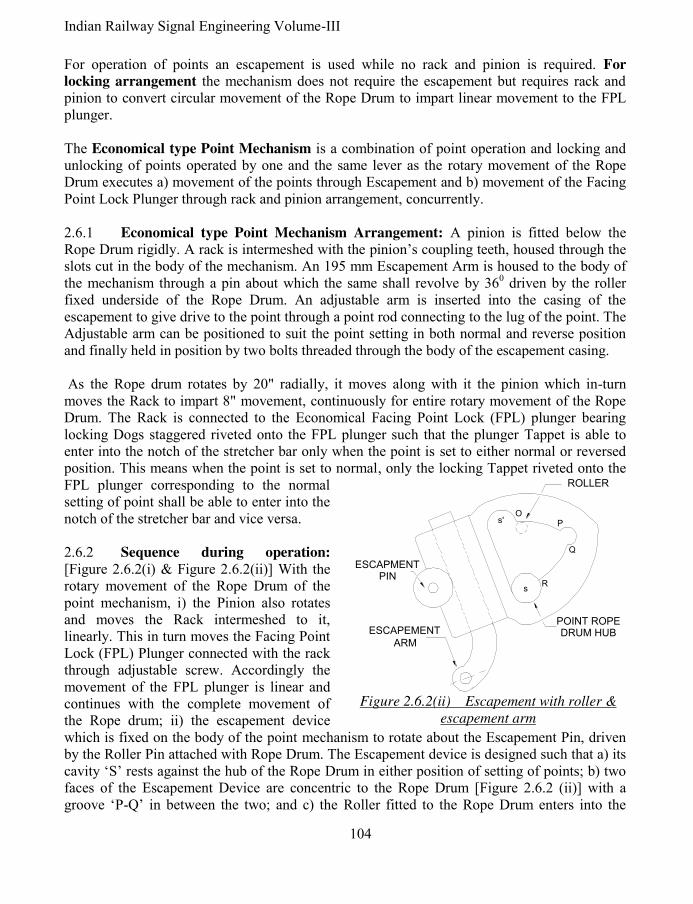
Indian Railway Signal Engineering Volume-III
104
For operation of points an escapement is used while no rack and pinion is required. For
locking arrangement the mechanism does not require the escapement but requires rack and pinion to convert circular movement of the Rope Drum to impart linear movement to the FPL plunger. The Economical type Point Mechanism is a combination of point operation and locking and unlocking of points operated by one and the same lever as the rotary movement of the Rope Drum executes a) movement of the points through Escapement and b) movement of the Facing Point Lock Plunger through rack and pinion arrangement, concurrently. 2.6.1 Economical type Point Mechanism Arrangement: A pinion is fitted below the Rope Drum rigidly. A rack is intermeshed with the pinion’s coupling teeth, housed through the slots cut in the body of the mechanism. An 195 mm Escapement Arm is housed to the body of the mechanism through a pin about which the same shall revolve by 360 driven by the roller fixed underside of the Rope Drum. An adjustable arm is inserted into the casing of the escapement to give drive to the point through a point rod connecting to the lug of the point. The Adjustable arm can be positioned to suit the point setting in both normal and reverse position and finally held in position by two bolts threaded through the body of the escapement casing. As the Rope drum rotates by 20" radially, it moves along with it the pinion which in-turn moves the Rack to impart 8" movement, continuously for entire rotary movement of the Rope Drum. The Rack is connected to the Economical Facing Point Lock (FPL) plunger bearing locking Dogs staggered riveted onto the FPL plunger such that the plunger Tappet is able to enter into the notch of the stretcher bar only when the point is set to either normal or reversed position. This means when the point is set to normal, only the locking Tappet riveted onto the FPL plunger corresponding to the normal setting of point shall be able to enter into the notch of the stretcher bar and vice versa. 2.6.2 Sequence during operation: [Figure 2.6.2(i) & Figure 2.6.2(ii)] With the rotary movement of the Rope Drum of the point mechanism, i) the Pinion also rotates and moves the Rack intermeshed to it, linearly. This in turn moves the Facing Point Lock (FPL) Plunger connected with the rack through adjustable screw. Accordingly the movement of the FPL plunger is linear and continues with the complete movement of the Rope drum; ii) the escapement device which is fixed on the body of the point mechanism to rotate about the Escapement Pin, driven by the Roller Pin attached with Rope Drum. The Escapement device is designed such that a) its cavity ‘S’ rests against the hub of the Rope Drum in either position of setting of points; b) two faces of the Escapement Device are concentric to the Rope Drum [Figure 2.6.2 (ii)] with a groove ‘P-Q’ in between the two; and c) the Roller fitted to the Rope Drum enters into the
s'
sR
O
Q
P
ESCAPEMENT
ARM
ESCAPMENT PIN
ROLLER
POINT ROPE DRUM HUB
Figure 2.6.2(ii) Escapement with roller &
escapement arm

105 Pramod P. Goel
groove ‘P-Q’ and drives the Escapement Device to be set against the hub of the Rope Drum which is against its opposite cavity S'. This movement of the Escapement Device moves the Escapement Arm to drive and set the point, connected through a solid rod, from normal to reverse and vice versa. The full rotary movement of the Rope Drum is used to unlock, operate and relock the point. As the Rope Drum starts moving, the FPL plunger, i) unlocks point first during the idling of the escapement device while the roller moving against its concentric surface ‘O-P’, ii) continues to move in the direction same as it was moving, while the roller gets engaged with the cavity ‘P-Q’ and moves the escapement device along with, concurrently, thereby setting the point to position other than to which it was set, with its cavity resting against the hub of the Rope Drum, before the locking dog catches with the stretcher bar, iv) the roller gets out of the cavity ‘P-Q’ and continues to move against second concentric surface ‘Q-R’ of the Escapement Device and rests against the hub of the Rope Drum having set the point to the other position, during this period of idling of the Escapement Device, the roller finally rests at the position ‘S’ till the next operation of point, v) the locking plunger continues to move and locks the stretcher bar while the escapement rests against the Rope Drum hub into the cavity opposite to S'.[See table 2.6.2(iii)]. It may be observed that unlocking stroke of the locking plunger is larger than the locking stroke as the unlocking stroke covers unlocking of the stretcher bar and the allowance for operation of points from normal to reverse or vice versa. Thickness of each stretcher bar being 3/4", two stretcher bars overlapping each other make the total thickness of the stretcher bars as 1½". To cater for marginal splitting of the pair of stretcher bar the locking stroke is kept as 1-5/8". While relocking an additional margin of 1/16" to the locking stroke is kept as to avoid premature attempt to lock while points are yet in the process of setting. 2.6.3 Broken Wire Lock Design & Function: Point Mechanism has been designed to take care of broken wire conditions also.
Stroke Rack
Movement Rope Drum Movement
Unlocking stroke 51 mm 127 mm
Point setting stroke 107 mm 268 mm
Relocking Stroke 42 mm 105 mm
Total rack movement 200 mm Total Rope drum movement: 500 mm
Table 2.6.2(iii) stroke versus rope drum movement
WIRE ROPE
DRUMPOINT MECHANISM
PINION
SPRING
LOCK PAWLS
Figure 2.6.3.1 Broken Wire Lock

Indian Railway Signal Engineering Volume-III
106
2.6.3.1 Broken Wire Lock Design: The broken wire lock is an assembly of two lock pawls pivoted on the periphery of the drum of Point Mechanism and Drum Lock. Each lock pawl protrudes beyond the pivot on both ends, one end designed to hold the Drum lock and other connect to both the Lock Pawls with a spring at extreme end of the pawls and wire rope, forming the loop ending onto the arm of these Lock pawls held in between the spring and the pivot. 2.6.3.2 Broken Wire protection by Drum Lock: Each Rope wire of the paired wire loop is connected with the arm of the Lock Pawl and wrapped around the Rope Drum, forming a pair of the wired loop which keeps both the Lock Pawls stretched apart against the spring connecting the two, keeping both away from the Drum Lock, under normal circumstances. As the lever is pulled to operate the point, the tension in the pulled wire increases as compared to the tension in return wire, making the Point Mechanism Rope Drum to rotate, as well as keeping the spring connecting both the Lock Pawls stretched enough to keep them away from the Drum Lock. As the lever is set to the position other than the original i.e. normal or reversed, and the tension difference between the pull and return wire is reduced to zero the springs connecting the Lock Pawl pulls both the arms together to engage them with the Drum lock [Figures 2.6.3.1 & 2.6.3.2] As the wire of paired loop breaks, a tension difference is created between the two wires causing the Lock Pawl connected to the broken wire to be pulled by the spring, pulling both the Lock Pawls together, engage itself with the Drum Lock which is fixed with the Point Mechanism Bracket and is rigidly held in position. 2.6.4 Economical type facing point lock:
The facing point lock is in three major parts, i) the case to house the, ii) plunger, and iii) Cross slide arrangement for proving plunger in. See figure 5.4.2 of Section-I of this book. While the case is similar to the facing point lock the plunger is different in shape & design for the reason that it has to unlock, keep margin while moving on for points which were idling so far, to move and then relock the stretcher bar when the points are set. The arrangement is termed economical as the locking unlocking and movement of points and proving of the plunger in is carried out by single stroke while the point is being set for normal and vice-versa. The plunger for Economical Facing point lock is 2" (49.8 mm) wide steel bar onto which 38 mm (1½") wide two lock dogs are fitted 158 mm (6.25") apart, staggered each with other by 12 mm (½"). This arrangement is to ensure locking of the point for correct route. This means that unless the points have responded to the lever movement, they should not get locked. If the points do not
Figure 2.6.3.2 Drum Lock
Movement of plunger Corresponding Cross slide stroke
3/8" 9 mm Idle Idle
1-5/16" 33 mm 5/8" 16 mm
4-7/8" 122 mm Idle Idle
1-5/16" 33 mm 5/8" 16 mm
1/8" 3 mm Idle Idle
Total 8" 200 mm 1¼ " 32 mm
Table 2.6.4

107 Pramod P. Goel
move due to a disconnection in the throw rod, but the plunger moves, the locking dog will recede out of the stretcher bar notches, but the other dog will not be able to enter the other displaced by 12 mm from the alignment of this second dog. Full stroke of the point mechanism cannot be completed under the above circumstances and therefore, when the lever is force latched, it will trip indicating the fault. A cam-path is fitted underside of the plunger to which two roller followers attached to the Cross slide, move along side of the cam-path. The Cross slide gets strokes as tabled numbered as 2.6.4. The lock slide moves along with cross slide connected with. Accordingly the net movement 200 mm (8") of the lock plunger is converted to 32 mm (1¼") of the Lock Slide. See figure 2.6.4 on the next page, for plan and side view of the Facing Point Lock Plunger. Until the Cross slide movement is completed, the rim of the detector shall be obstructed and it shall not be possible to operate the lever to set fully whether the detector is independent or in series of signal wire run. 2.7 Maximum distance up to which the point and signal can be operated: With the 500 mm (20") stroke lever the maximum distance for operation is specified in SEM is 550 yards with transmission length as 1650 feet and pulley spacing as 45 feet. A loss of stroke, which may be due to friction, shall cause a tension difference between the paired wires loop being 186 lbs. In case of point mechanism operation where the stroke on the point switches is to be imparted is 125 mm (4½") only, a minor loss of stroke to points due to some obstruction, which should be able to trip the lever, shall not happen to trip if the clutch is adjusted precisely to 62 lbs. As such for point operation the clutch shall be required to be adjusted at a bit lower than 62 lbs measured on dynamometer. 2.8 Rod Transmission: When transmission for operation of Points, locks, lock bar and holding bar is rod, it is same as detailed in system of single wire signalling section of this book, except for the lever when done from the double wire lever frame is rack & pinion lever.
*****

Indian Railway Signal Engineering Volume-III
108
3/4
"3
/4"
2"
8.2
5"
6.2
5"
Fig
ure
2
.6.4
E
conom
ical
faci
ng P
oin
t lo
ck p
lunger
pla
n &
sid
e vi
ew
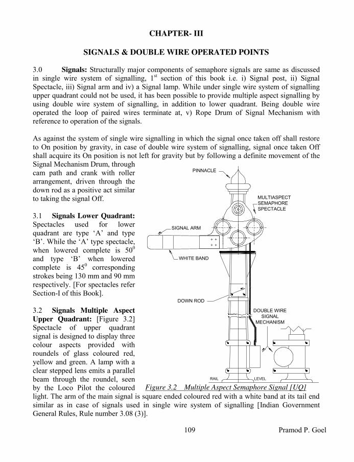
109 Pramod P. Goel
CHAPTER- III
SIGNALS & DOUBLE WIRE OPERATED POINTS 3.0 Signals: Structurally major components of semaphore signals are same as discussed in single wire system of signalling, 1st section of this book i.e. i) Signal post, ii) Signal Spectacle, iii) Signal arm and iv) a Signal lamp. While under single wire system of signalling upper quadrant could not be used, it has been possible to provide multiple aspect signalling by using double wire system of signalling, in addition to lower quadrant. Being double wire operated the loop of paired wires terminate at, v) Rope Drum of Signal Mechanism with reference to operation of the signals. As against the system of single wire signalling in which the signal once taken off shall restore to On position by gravity, in case of double wire system of signalling, signal once taken Off shall acquire its On position is not left for gravity but by following a definite movement of the Signal Mechanism Drum, through cam path and crank with roller arrangement, driven through the down rod as a positive act similar to taking the signal Off. 3.1 Signals Lower Quadrant:
Spectacles used for lower quadrant are type ‘A’ and type ‘B’. While the ‘A’ type spectacle, when lowered complete is 500 and type ‘B’ when lowered complete is 450 corresponding strokes being 130 mm and 90 mm respectively. [For spectacles refer Section-I of this Book]. 3.2 Signals Multiple Aspect
Upper Quadrant: [Figure 3.2] Spectacle of upper quadrant signal is designed to display three colour aspects provided with roundels of glass coloured red, yellow and green. A lamp with a clear stepped lens emits a parallel beam through the roundel, seen by the Loco Pilot the coloured light. The arm of the main signal is square ended coloured red with a white band at its tail end similar as in case of signals used in single wire system of signalling [Indian Government General Rules, Rule number 3.08 (3)].
LEVELRAIL
MULTIASPECT
SEMAPHORE
SPECTACLE
PINNACLE
SIGNAL ARM
DOWN ROD
WHITE BAND
DOUBLE WIRE
SIGNAL
MECHANISM
Figure 3.2 Multiple Aspect Semaphore Signal [UQ]

Indian Railway Signal Engineering Volume-III
110
When used as Distant Signal, the arm is fish tailed painted yellow with a fish tailed white band near the tail end of the arm. Another lamp with a lens coloured yellow is fixed 1.5 metres below the lamp used for signal arm, placed on the same post, designed such that the lamp is covered by a metal sheet in 00 (normal) and 900 (Off position) and is exposed to display second yellow light with the signal’s arm is inclined 450 up [Indian Government General Rules, Rule number 3.07 (3)]. 3.3 Signal Post: Tubular as well as lattice signal posts are used to mount spectacles and signal mechanism. The signal mechanism is fixed onto the signal post by ‘U’ clamp holding the base of the signal mechanism in case of tubular post. In case of lattice post Angle iron is fixed onto the lattice post extended to hold the signal mechanism through its base. 3.4 Signal Mechanism: Owing to the double wire system of semaphore signalling the paired wire run forms a loop on the Rope Drum of the double wire lever at one end and on the Rope Drum of Signal Mechanism, onto the independent Rotary Detector or Detector in series of the paired wire run, at other end. Ultimately the rotary movement of the Rope drum of the Signal Mechanism has to be converted into linear movement to provide up and down stroke to the spectacle through down rod connected at one end to the crank of the Signal Mechanism and to the spectacle onto the signal spectacle on the other end. The linear movement of the down rod again gets converted into rotary movement of the spectacle rotating about the hub. For converting the rotary movement of the signal mechanism drum, into linear movement of the down rod, a mix of concentric and eccentric cam path is designed into which a follower roller moves having been fitted at the end of the one arm of the crank, the other arm of which is connected to the down rod at one of the holes in the arm, to adjust amount of throw to the down rod. The Signal Mechanism Drum is mounted on a bracket and is provided with the cover against outside interference. The Crank is pivoted onto its hub pin fixed on the Bracket of Signal Mechanism. The assembly consisting of the drum and the bracket along with the crank constitutes the Signal Mechanism. The Bracket is mounted on the tubular or lattice signal post as the case may be. The cam path of the drum is designed not only to provide linear movement to the down rod but also to cater for extra rotary movement for stabilizing the signal including wire breakage conditions due to over run. It is the eccentric pathway which provides stroke to the down rod transmitted by the crank while the concentric path way is to take care of i) variation in loss of stroke in transmission, ii) variation in uncompensated length of transmission wire between coupled signals, iii) minor maladjustments in the transmission and iv) to cater for outside interference to keep the signal stabilized after having been taken Off or to throw the signal On, under wire breakage conditions. Accordingly the stroke imparted by the lever can be put in sections, i) initial idle stroke of 137 mm, allowance to cover-up variation in the loss of stroke while putting lever from reverse to normal, to stabilise the On aspect, ii) the working stroke 250 mm for operating the signal and iii) final idle stroke of 113 mm to stabilise the Off aspect to cover up variations due to loss in

111 Pramod P. Goel
stroke when the lever is operated from normal to reverse. Accordingly the net stroke imparted by 500 mm (20"), gets distributed as detailed above. Signal Mechanism is said to be left hand when the crank arm connected to the signal, Down Rod is placed left hand with reference to the centre of the signal mechanism when viewed by the observer facing the mechanism and vice-versa for right hand. The left hand or
right hand signal mechanism can be fixed onto the signal post by making suitable alterations to the mechanism. A pendulum is provided concentric to the hub of the signal mechanism drum with Stop fixed onto the bracket to limit the movement of the drum. This arrangement is called as Signal
Mechanism Drum Lock and is used to i) arrest the motion of the Signal Mechanism drum as soon as the signal assumes On, ii) limit broken wire stroke at the compensator, and iii) make the signal aspect immune to the rotation of the drum due to inertia in case of wire breakage. The push-pull coupled signal mechanism shall have only one stop as the signal mechanism drum is likely to rotate in any direction while the signal mechanism drum for single (uncoupled) lever shall have two stops to prevent its rotation other than to normal. Signal Mechanism is nominated with respect to the position of the signal which could be attained by using the said signal mechanism. For example 450-0-900 signal mechanism shall cause the signal to acquire 450 inclined upwards to horizontal when the Signal mechanism drum rotates clockwise with reference to its neutral position i.e. when the signal arm is horizontal. However when the Signal mechanism drum is made to rotate anticlockwise from its neutral position the signal arm shall acquire 900 above horizontal. Accordingly this arrangement is termed as Left hand 450-0-900 Signal Mechanism. 3.4.1 Signal Mechanism for Pull-Pull arrangement of Lower Quadrant: 3.7/16" stroke is imparted to the down rod of lower quadrant ‘B’ type signal. Lower Quadrant, Double Wire, Pull-Pull coupled Signal mechanism is used for two lower quadrant signals on one and the same post. It may be observed that as the lever-1 is to take the outer signal Off, the Warner may be taken off by pulling second lever in succession. As may be seen in figure 3.4.1, while crank
PENDULUM
CRANK-1CRANK-2
DRUMBRACKET
Figure 3.4.1 L.Q. (DW) Pull-Pull coupled
Signal mechanism
BRACKET
CRANK
8.5
" S
TR
OK
E
DRUMROLLER
ROLLERPATHWAY
PENDULUM
Figure 3.4.2 (U.Q.) D.W. Signal Mechanism
450-0-90
0

Indian Railway Signal Engineering Volume-III
112
-1 shall lift the down rod the Outer signal number-1 shall be taken Off without affecting any movement to crank-2, its pathway being concentric. As and when lever number-2 is pulled, the crank-1 shall remain affected following concentric path while the crank-2 shall follow the eccentric path to lift the down rod of the Warner signal. 3.4.2 Signal Mechanism 45
0-0-90
0 for Upper Quadrant, Push-Pull arrangement: Upper Quadrant, Double Wire signal to Push-Pull coupled 450-0-900 Signal Mechanism [Figure 3.4.2] is to take the signal Off for 450 by lever-1 rotating the signal mechanism drum in clockwise direction and with this lever normal, operation of lever-2 rotates the signal mechanism drum in anticlockwise direction putting the signal to 900 directly. This Signal Mechanism works a three aspect Starter Signal and also used to work a Distant Signal, shown in the figure is for right hand Signal Mechanism. 216 mm (8 ½") stroke is imparted to the down rod to raise the signal arm to 900 upwards. Stroke imparted on the down rod shall be different for Type ‘A’ and type ‘B’ spectacles and also for different strokes downwards or for 450 & 900 upwards. 3.4.3 Signal Mechanism for Upper Quadrant,
single transmission for 0-450 position: This
mechanism is used for single transmission required to work one signal only, for its 450 position, such as loop line Home Signal, loop line starter signal and shunt signal. The stroke imparted to the down rod is 108 mm. [See figure 3.4.3]. 3.4.3.1 Signal Mechanism for Upper Quadrant,
Push-Pull arrangement 0-0-450: In this case same
signal Mechanism is used as that used for 0-450 arrangement, for two signals on different signal posts for operation of one or both push-pull coupled signals. The signal Mechanism is same for both arrangements of 0-450 and 0-0-450 except for the signal mechanism of 0-450 arrangement shall have two stops, while for arrangement 0-0-450 it shall have one, the normal stop. See the figure 3.4.3.1 for Upper Quadrant, Push-Pull Mechanism, 0-450 or 0-0-450 the trajectory followed by the roller of the crank is shown dotted. 3.4.4 Signal Mechanism for Upper Quadrant Pull-Pull arrangement 0-45
0-90
0: See the
figure 3.4.4, as the lever-1 is pulled the signal mechanism drum rotates clockwise causing the crank to raise the down rod as the roller moves into the pathway to take the signal Off to 450. With the pulling of lever-2 the crank arm causes the rise of down rod further to take the signal Off to 900.
DRUM
BRACKET
PENDULUM
CRANK
Figure 3.4.3 & 3.4.3.1 (U.Q.) D.W.
Signal Mechanism 0-450 or 0-0-45
0

113 Pramod P. Goel
3.4.5 Other Signal Mechanisms for Upper Quadrant: Other Signal Mechanisms with different requirements are discussed in ensuing paragraphs. 3.4.5.1 Signal Mechanism with Pull-Pull
arrangement 0-900: This Mechanism is used for
operation of single signal to take the signal Off to 900 only such as main line starters or Last Stop Signal (LSS) such as Starter and Advance starter. The stroke imparted to the down rod is 216 mm. 3.4.5.2 Signal Mechanism with Push-Pull
arrangement 0-0-900: The Signal Mechanism is
used to operate main line starter to the 900 position when coupled Push- Pull with another signal on a separate post. The only difference between 0 - 900 and 0- 0-900 signal mechanism is that the first one has two stops and the second one only one. 3.4.5.3 Signal Mechanism with Push-Pull
arrangement 450-0- 45
0: As and when one signal
leads to two different routes, it is operated by either of the two different levers to take it Off to 450 for the sake of interlocking arrangements. 3.4.5.4 Signal Mechanism with Push-Pull arrangement 90
0-0- 90
0: Similar to the 450-0-
450 Mechanism, operated by two different levers, this arrangement is used for one signal leading on two different routes, except for the high speed turnouts which allow higher speed over the turnouts permitting the signal to be taken Off to 900. 3.4.5.5 Signal Mechanism with Pull-Pull arrangement: 0-450-900 Signal Mechanism:
Used for working three aspects signals such as Main Line Home or Distant Signals 0-450-900 is
a pull-pull signal mechanism. Under this arrangement one signal lever is pulled to impart 450 position and then operated by the other signal to impart 900 position. 3.4.6 Signal Mechanism with Push-Pull Upper Quadrant using Double Cranks: The Signal Mechanism is used for two conflicting upper quadrant signals on the same post. It has 450 aspect only using Push-Pull coupling arrangement. The down rod imparts 108 mm stroke.
*****
BRACKET
PENDULUM
ROLLERPATHWAY
CRANK
DRUM
Figure 3.4.4 (U.Q.) D.W. Signal
Mechanism 00-45
0-90
0
Indian Railway Signal Engineering Volume-III
114
CHAPTER- IV
MONITORING, LOCKING & SAFETY DEVICES 4.0 Wire breakage, associated conditions and broken wire protection: As against single wire system of operation, the double wire system of operation covers operation of signals, points, facing point locks and detectors. Accordingly both the paired wires under double wire system of operation are kept under tension by double wire compensators. This in turn if causes breakage of any one of the paired wire to create unsafe conditions due to the compensator weight start falling out of gravitational force, to the extent of broken wire stroke available on the ratchet rod (of the compensator), pulling both wires. This may operate point, signal or the detector, creating unsafe conditions when a train movement is scheduled to or taking place. Measures taken to safeguard such unsafe conditions are i) tripping of clutch levers, ii) Broken wire stroke provided on the ratchet rod of the compensator and iii) over run pathway provided on the Signal Mechanism drums and signal mechanism drum-Lock. 4.1 Affects of tripping of Lever Rope Drum of the Clutch Lever: As the tension difference is created due to an obstruction in the transmission or breakage of any one of the paired wire loop, the lever shall trip, as and when the tension difference rises by 85 kg or beyond, adequate enough to trip the lever Rope drum. Since tripping of the lever rope drum is safety sensitive, the adjustment for allowing tripping shall be kept critically 85 kg or below but not lesser than 72 kg. This tripping of the Lever Rope Drum, i) shall impart 12 mm movement to the locking plunger (Tappet) in the direction last operated and, ii) shall also cause 75 mm (3") rotation of the lever rope drum. This movement of the lever rope drum shall impart 75 mm movement to the mechanism drum due to tripping. However if two coupled levers trip together the mechanism drum shall rotate by half which is 37.5 mm. This rotation of drum may be forward or backward depending upon position of wire breakage. Affect of tripping on mechanism drum under situations and different point of breakage shall be
discussed in ensuing paragraphs. 4.1.1 Affect of tripping of Lever Rope Drum on interlocking: Tripping of Lever Rope Drum shall impart 12 mm motion to the locking plunger (Tappet) activating interlocking. It shall depend upon the design of Locking Table (Dog-Chart) whether the locking provided is loose or tight. In case of locking being loose, it shall not cause any affect on the interlocking due to tripping but in case of locking being tight the tripped of the lever shall cause the affected lever to be locked in last operated position. 4.1.2 Affect of tripping of Lever Rope Drum resulting in its movement forward or
backward: The Lever Rope Drum rotates due to uneven tension between the paired wires of the loop due to its tripping. This rotary movement of the Lever Rope Drum may be forward or
115 Pramod P. Goel
backwards depending upon the position of breakage in the wire creating uneven tension between the two paired wires of the loop. 4.1.2.1 Forward and backward movement of the wire with the tripping of Rope Drum:
Considering that, under the coupling arrangement, the return rope wire connected to the coupling device lever, breaks the coupling device lever shall fall almost vertical while the Rope wire on pull side of the lever drum, which is intact and firmly wrapped upon the Lever Rope Drum shall cause the wire to be pulled by the falling weights of the compensator, making the Lever Rope Drum to rotate in the direction which is opposite to the direction when the lever is pulled to be set on reversed position. This implies that the movement of the wire rope due to this tripping is “backwards” and vice-versa. This shall also be read as imparted stroke by the lever due to tripping. 4.2 Affect of wire breakage on equipment operated: As a wire out of the paired wire loop breaks a tension difference is created between the pair of wire loop one wire being free and other under tension. The Compensator lever wheel starts rising due to weight trying to fall down under condition of no or negligible tension on the wire broken. Since both the levers of the compensator are coupled the compensator lever which is free of tension shall take along with it the intact wire also. The intact wire while being pulled shall cause to, i) impart tension on the associated clutch lever drum to cause it to trip if the force is enough to trip the lever rope drum on one end and, ii) rotate the Mechanism Drum of the signal, point or detector under associated conditions. The pull on the intact wire shall be limited by Signal Mechanism Drum Lock, Detector’s Control Rim or the point machine lock as the case may be. There may be conditions under which the detector may rotate unrestricted when detecting normal set point. The details may be seen in ensuing paragraphs. This rotation of the Mechanism drum of signal, point or detector under associated conditions, may create unsafe conditions to be investigated under the Broken Wire Protection subject. 4.3 Movement in case wire breakage under coupling arrangement: As a coupled lever is pulled it locks the associated coupled clutch lever, during operation, to prevent the initial wire tension imbalance causing the other lever to trip as the lever which is being pulled can not trip while it is on the Quadrant and by the time the lever is put to rest on either position the tension difference between the paired wire loop becomes settled and as such normal, below the tension range of tripping. There may be combinations of direct lever and clutch lever; and clutch lever & clutch lever. Only the direct lever shall lock the clutch lever in, direct to clutch lever combination and either of the paired clutch lever shall lock the other under clutch lever–clutch lever combination. As one of the paired wire of the loop breaks, it causes i) falling of the Coupling Device Lever, and ii) rising of the compensator lever wheel both resulting in pulling of both ends of the compensator lever wheel, the intact wire. This shall cause pull of the wire, double the rise of the compensator lever wheel.

Indian Railway Signal Engineering Volume-III
116
The Coupling Device Lever is 500 mm long with its one end hinged on a support. The wheel on the coupling device lever is placed at half the length of the Coupling device lever, on a pivot 250 mm from the hinge. As the wire breaks, the wheel shall fall by 125 mm as the coupling device lever shall fall about its hinge almost to vertical. In case the lever is pulled the drop of the Coupling Device Lever wheel shall be 375 mm (15"). 4.4 Postulates of interlocking, under broken wire conditions: Under the postulates of
interlocking, under broken wire conditions, i) Signal with the lever normal- The signal shall continue to be On; with lever reversed the signal shall continue to be Off , may acquire less restrictive aspect or preferably go to On; ii) Points- set to either way should remain in last operated position or if at all have to move they shall set completely to either position keeping no gap between switch rail & stock rail; iii) Detectors- A detector is functional only when its lever is reversed otherwise it has no role to play, as such when detector lever is reversed, it should continue to hold the points in last operated position, iv) Clutch lever- Lever Drum must trip to foul the interlocking if locking is tight. 4.5 Broken wire protection for signals and Detectors: Broken wire protection for, A) Signal when- i) lever normal, ii) lever reversed, iii) Push –Pull coupling, iv) Pull-Pull coupling, v) signal wire run without Detector in series and, vi) signal wire run with Detector in series; B) Point, C) Detector, D) Clutch lever and E) coupling arrangements, shall be to comply with the postulates of interlocking, under broken wire conditions as discussed in preceding paragraph. 4.5.1 Broken wire protection for signal: When movement of the Signal mechanism drum takes place in the direction same as that of taking the signal Off, the broken wire stroke on Double Wire Compensator is used as Overrun Stroke on Signal Mechanism. The Over Run Stroke is kept larger than the lever stroke used to stabilise the signal in Off position and is meant to replace the signal to On. The broken wire stroke is kept larger than compensation stroke on the double Wire Compensator, which provides Overrun stroke to the Signal Mechanism drum, while rotating. 4.5.1.1 Broken wire protection for single signal & no detector in wire run for the given
signal: Broken wire protection for signal when lever normal: When the wire breaks between lever and the compensator- As the return wire breaks, the weight on the Compensator Lever shall fall, having been left with no tension in the wire, concurrently lifting the wheel on the other end of the Lever to the extent of Wire Breakage Stroke. Suppose the wheel falls by 150 mm it shall create a gap of 300 mm in between both ends of the wire broken. Both Compensator Levers falling together, the other Compensator Lever with intact wire (Pull wire) shall also be pulled by 300 mm, causing i) the drum of the signal mechanism to rotate by same amount as well as, ii) result in increasing the gap between broken ends of the wire by 600 mm doubling the gap. This establishes the rule that the movement of the rope drum of the Mechanism is half the gap
between broken ends of the wire.

117 Pramod P. Goel
As the Pull wire breaks between the Lever and the Compensator, the return wire shall get pulled to rotate the signal drum of the Mechanism in the direction opposite for taking the signal Off getting locked in position after covering the initial idle stroke without affecting the signal aspect. Accordingly applying the same principle on coupled levers, a break in one of the coupling loops between lever and the compensator, in case of Push-Pull coupling arrangement the drop of the coupling wheel shall be 125 mm causing the gap between broken wire ends as 250 mm, causing movement of the signal mechanism by 125 mm which is equal to the drop of the wheel.
4.5.2 Broken wire protection for Rotary Detector: The role of rotary Detector comes in only when the lever of Detector or Signal with Detector in series, is reversed. There could be conditions i) Detector operated by an independent lever, ii) Detector is wired in series with a signal and iii) Detector and signals are operated under coupling arrangement. 4.5.2.1 Detector operated by an independent lever; pull wire Broken: Detector’s Detection Rim is extended up to Control Rim to cater for rotation of the detector drum when the last pulled wire (pull wire) is broken. If the pull wire is broken with lever in reversed position, the detector wheel shall rotate in the direction same which caused the lever operation from normal to reverse, which in turn shall cause the detector to keep the detector slides held in last operated position of points by the Detecting Rim or extended to the Control Rim as the case may be. 4.5.2.2 Detector operated by an independent lever; return wire Broken: In case of breaking of return wire, the detector drum rotates in direction opposite to the lever being pulled as if the lever was being put back to normal from reversed position. However, in this case, the Detector moves further to hold the points engaged by the locking rim. 4.5.3 Broken wire protection for signals under coupling arrangement, without
detectors: Two levers operate either of the two signals placed on the same post by one and the same Signal mechanism. Since it is push-pull arrangement the paired wires of the loop work as pull-1 and pull-2. 4.5.3.1 Break in coupling loops: There may be conditions under which both Signal levers are normal, Signal-1 lever reversed or Signal lever-2 reversed. i) Condition under which both Signal levers are normal: With breakage of any of the two pull-1 or pull-2 wires the Coupling Device Lever Wheel shall drop down by 125 mm being almost vertical about the fulcrum causing the Rope drum of Signal Mechanism to move backward by 125 mm, sufficient to take the signal-2 Off, consequently resulting in the compensator wheel to rise by 62.5 mm (half of fall of Coupling Lever). If the lever-1is free to trip, the tripping of the Rope Drum shall result in drum to rotate forward by 37.5 mm with the net movement of the Signal Mechanism being backward by 87.5 mm (125-37.5 mm). The over run cam-path shall cause the Signal back to On.

Indian Railway Signal Engineering Volume-III
118
ii) Condition under which Signal lever-1is reversed: With breakage of wire of coupling loop of lever-1 Signal Mechanism shall move backwards as if being set to normal position simultaneously dropping down of the Coupling Devise Lever wheel by 375 mm, from its original lifted position of 250 mm above the fulcrum, causing in turn the Signal Mechanism to put the signal back to On moving by 375 mm to normal position of the lever. The compensator lever wheel shall rise by 187.5 mm. If the Rope Drum of lever-1 trips, it shall result in 37.5 mm movement of the rope drum in direction opposite to the one caused due to the wire breakage resulting in Signal Mechanism to move 337.5 (375-37.5) mm, signal to cause to droop due to reduction in over all movement of the Signal Mechanism. Lever-2 cannot trip having been drum locked due to lever-1, being reversed. iii) Condition under which Signal lever-2 is reversed: Similar conditions shall prevail when the lever-2 is reversed when the wire breaks. 4.5.3.2 Break in wire transmission: There may be conditions under which both Signal levers are normal, Signal-1 lever reversed or Signal lever-2 reversed. i) Conditions under which Both Signal levers are normal: Due to break in wire of
coupling loop of lever-1, the Compensator Lever wheel shall rise by 387.5 mm (15½") causing the return wire to be pulled by 775 mm (31") and signal drum being stopped by the signal mechanism lock and double the rise of the compensator lever wheel. This shall cause the signal-2 to go to Off position momentarily coming back to On. Similar shall be action in case of breaking of wire pull -2. ii) Signal Lever-1 is reversed: Due to break in wire of coupling loop of lever-1, two situations may arise, the return wire shall pull i) 775 mm (31") signal drum being stopped by the signal mechanism lock, or ii) 775+500 mm=1275 mm (31"+20"=51") signal drum being stopped by the signal mechanism lock in opposite direction. In condition (i) the signal number -2 shall go to Off aspect momentarily and return to normal and condition (ii) Signal number-1 shall go to On and signal number-2 shall go to Off momentarily and then to On. iii) Signal Lever-2 is reversed: Similar action shall take place when pull-2 wire is broken. In both the cases the lever if free shall trip which in-turn shall cause the Compensator Lever Wheel to rise and accommodated by the compensator wheel without affecting the Rope drum of the Signal mechanism. iv) Signal Lever-1 is reversed: Due to break in wire of coupling loop of lever-2,
signal Mechanism Rope Drum shall rotate by 125 mm in over run direction due to Coupling

119 Pramod P. Goel
Device Lever of lever-2 dropping by 125 mm and compensator wheel rising by 62.5 mm (half of the fall of coupling loop lever by 125 mm). Due to idle over-run being only 110 mm the drum shall cause the signal to droop short of being to On. To avoid this, the lever-1 shall be put back to normal due to which lever-2, which was locked when the lever-1 was being reversed, shall also trip resulting in reverse movement of the Signal Mechanism Drum by 37.5 mm putting the signal back to On. 4.5.4 Broken wire protection for signal with detectors in series: There are two arrangements, one being in which Detector is operated by an independent lever and the signal lever is pulled there after back-locking the detector lever. In other method the Detector is put in series with the paired wire loop to operate signal while concurrently detecting the associated point. The operation of independent signal and independent detector has been discussed in preceding paragraphs; the Detector in series with the signal is discussed herewith as follows. 4.5.4.1 Wire break in coupling loop, both Signal levers normal, points normal and
detector in series with signal transmission: i) Broken wire protection due to break in wire of coupling loop of Signal lever-1: The Detector shall be restricted to move more than 100 mm restricting the signal mechanism drum also to rotate through initial idle cam path of signal-2, of the signal mechanism drum, by 100 mm. The compensator wheel shall also be restricted to rise by 50 mm only. This shall keep both the signals at On. Tripping of the lever shall cause the compensator wheel to rise to 87.5 mm reversing the rotation of the signal mechanism drum, resulting in return of transmission wire due to tripping, by 37.5 mm, without change in status. Similar shall be the condition if points are reversed and coupling loop of lever-2 breaks. ii) Broken wire protection due to break in wire of coupling loop of Signal lever-2:
With the break of wire in coupling loop-2, the Detector shall be free to rotate unrestricted, when points are set to normal, controlled by signal mechanism lock. This shall not affect the signals being kept at On. 4.5.4.2 Break in transmission paired wire loop between lever and detector: Two signals on the same post under Push-Pull arrangement operated by one and the same signal mechanism. i) Points normal and both Signal levers normal: With the break in pull-1 wire, the compensator wheel shall rise by 50 mm (2") due to paired loop pull wire-2 causing the rotation of the detector being restricted by 100 mm (4") by the Control Rim (high rib) of normal detector, locking the point and rotating the Signal Mechanism Drum backwards by 100 mm (4"). However this shall not affect maintaining the signal position at On. Similar condition shall prevail when point is reversed and pull-2 wire is broken.

Indian Railway Signal Engineering Volume-III
120
ii) Points normal and both Signal levers normal: With the break in pull-2 wire, the compensator wheel shall rise by 387 mm (15½") due to paired loop pull wire-1 causing the Detector to rotate unrestricted, locking the point and rotating the Signal mechanism drum forward by 775 mm (31") on getting stopped by the signal mechanism lock. This shall not affect maintaining the signal position at On. Similar condition shall prevail when point is reversed and pull-1 wire is broken. iii) Points normal and Signal lever-1 reversed: With the break in wire pull-1, the compensator wheel shall rise by 300 mm (12"), causing the paired wire pull-2 to pull the wire and rotate the Signal Mechanism Drum backwards simultaneously rotating the Detector by 600 mm (24") restricted by the normal detector Control Rim (high rim). This shall cause the point to be locked by both detectors and putting the signal-1 back to On. Similar conditions shall prevail when point is reversed and lever -2 is reversed pull-2 wire is broken. iv) Points normal and Signal lever-1 reversed: With the break in wire pull-2, the Compensator Lever wheel shall rise by 137.5 mm (5½"), causing the paired wire pull-1 to pull the wire and rotate the Signal Mechanism drum forward by 275 mm (11"), held by Signal Mechanism Lock allowing the Detector Rope Drum to rotate unrestricted. The points are kept locked by normal detection rim & signal-2 going back to On. Similar conditions shall prevail when point is reversed and lever-2 is reversed and pull-1 wire is broken. 4.5.4.3 Break in transmission of paired wire loop between Detector and Signal: Two signals on the same post under Push-Pull arrangement, operated by common signal mechanism. i) Points normal and both signal levers normal: With the break in pull-1 wire, the compensator wheel shall rise by 387.5 mm (15½") due to break in paired loop pull wire-2, causing the rotation of the normal detector rim freely beyond 775 mm (31") (double the rise of compensator wheel) being ultimately restricted by the Control Rim (high rib) of normal detection wheel, locking the point and rotating the Signal Mechanism drum backwards by 775 mm (31") getting held by the Signal Mechanism Stop. This shall cause the signal-2 to go to Off momentarily and then back to On. Similar conditions shall prevail if the points are reversed and pull-2 wire breaks between detector and the signal. 4.5.4.4 Break in transmission paired wire loop when Signals are placed on separate
posts under Push-Pull arrangement: When two different signals are placed on different posts such as starters from different lines any one of the two shall be taken off at any one time. In this case two independent Signal Mechanisms shall be provided for each of the two signals. This

121 Pramod P. Goel
shall also necessitate use of two independent detectors provided in pull wire-1 and pull wire -2 of the paired loop. In this case all conditions of wire breakage under Push-Pull arrangement on two signals on the same post shall apply too even though two separate Signal Mechanisms are used. However the condition under which wire breaks between two signals are discussed as follows: i) Points normal and both Signal levers normal: As the wire between the two signals breaks the compensator wheel rises by 387.5 mm (13½") pulling both wires, making the Signal Mechanism Drums of both signals to rotate. As the signal-1 mechanism drum rotates forward, the signal-2 mechanism drum rotates backwards. This shall take the signal-1& signal-2 to Off momentarily and then to On as the both signal drums shall rest with the mechanism drum lock due to pull of wire by 775 mm (31") (double of the rise of compensator wheel). Similar conditions shall prevail if the points are reversed when the wire breaks. ii) Points normal and Signal-1 lever reversed: As the wire pull-1between the two signals breaks the compensator wheel rises by 137.5 mm (5 ½") pulling wires on both ends of the wheel, making the Signal Mechanism Drums of both signals to rotate. Wire Pull-1 shall rotate forward by 275 mm (11") restricted by Signal Mechanism Stop, causing the Sigal-1 to go to On while simultaneously the detector shall hold the point locked by its normal detection rim. Pull-2 wire shall be pulled back by momentum up to 127 mm (5") maintaining signal-2 to its On position. However the system can not be relied on chance and there is every likely hood of signal-2 going Off, resulting the Loco Pilot to lead the train onto the sand-hump. Similar conditions shall prevail if the points are reversed when the wire breaks creating further more difficult situation. 4.5.4.5 Signals provided with reversers: As and when signals are provided with reversers, there shall be no adverse affect on the signal with breakage of wire till the signal is not taken Off, and the reverser is not energised. 4.6 Broken wire protection for Point: The broken wire protection against Double Wire Point Mechanism is taken care by, i) Drum-Lock and , ii) Double Wire Rotary Detector, when operated. 4.6.1 Broken wire protection for Point by Drum Lock: Details of design and its function of broken wire protection for Point with Drum Lock may be seen at preceding paragraph 2.6.3, however broken wire protection by Double Wire Rotary Detector is detailed as follows. 4.6.1.1 Broken wire protection for Point by Rotary Detector: When the Detection is operated, the associated point is held in last operated position by the Detector Locking Rim. In case the detector is not operated, the point may be held in the last operated position by the Lever Locks engaged with the Lock Drum or if not engaged, it may move full round due to tension difference between paired wire loop till the tension difference is reduced so much so

Indian Railway Signal Engineering Volume-III
122
that Drum Lock Springs get pulled together to engage with the Drum Lock and hold points in position other than to which it was originally set before wire breakage. However the arrangement is not found to be very reliable and the facility of holding the point through detector slides by the rotary detector is used as supplement. 4.7 Layout Facing
Point Lock, Economical
Facing Point Lock & Lock
bar under double wire system of signalling: [Figure 4.8] A mechanical Facing Point Lock (FPL) operated by an independent lever, provided to hold the points in last operated position till the plunger is pulled out of the split stretcher bar of the points, is discussed in Section-1 (Single wire system of Mechanical Signalling) of this book. The plunger of the FPL is pushed inside or pulled out of the case of the lock, by rod running between the lever and the FPL plunger. 4.7.1 Economical Facing
Point Lock under double
wire system of signalling: Under the Double wire system of mechanical signalling, the point is not only locked but also is operated by the a rotary Point Mechanism by converting the rotary movement of the Point Mechanism Rope Drum to linear movement as discussed in preceding paragraphs of this section.
RA
CK
PO
INT
ME
CH
AN
ISM
LOCK BAR
LEADING
STRETCHER BAR
AD
JU
ST
AB
LE
CR
AN
K
HORIZONTAL CRANK
Fig
ure
4.7
P
oin
t la
yout
of
poin
t oper
ate
d b
y D
ouble
Wir
e poin
t M
echanis
m E
FP
L w
ith
lo
ck b
ar

123 Pramod P. Goel
As rack of the Point Mechanism moves back and forth it unlocks the points, pauses to allow the point to move and set it to the opposite side and relocks the point in last set position. To accommodate the requirements, as discussed, the lock plunger is designed accordingly. Since the entire set of operations including the lock is executed by one set of lever and paired loop of wires the FPL used for double wire is termed as Economical Facing Point Lock (EFPL). While the train traverses the station section, holding the route is another special feature of signalling system, which is achieved by providing Lock Bar and Holding Bars. 4.7.2 Lock-bar, under double wire system of signalling: The Lock Bar associated with EFPL is used to prevent movement of the lock plunger under the wheels of a train passing over or standing on the points. Accordingly the Rack of the Point mechanism gives drive to the associated Lock Bar, which in turn is connected to the plunger of the EFPL. It is pertinent to note here that the total drive of the Rack of the Point Mechanism is kept 8" (200 mm), to fit in operation of the Lock Bar back and forth and concurrently operation of the EFPL plunger. For EFPL plunger movement details refer table 2.6.4 in preceding paragraphs. As and when the distance between the Signal Post and the first point on the train’s route is more than 180 Metres, another independent Lock Bar termed as ‘Holding Bar’ shall be provided in between the lock bar associated to the point and the signal post, operated by another lever, back locked by the facing point lever enroute. This restriction of distance of 180 Meters shall be maintained for the given route up-till the destination, having cleared the last point in the route. 4.7.3 Economical facing point Lock and Lock bar: Out of Essentials of Interlocking as provided by the Signal Engineering Manual (SEM), i) Points falling in direction facing the train, are required to be held in position without allowing any gap (within reasonable limits) between the switch and stock rail and ii) it shall not be possible to change the setting of the point under the wheels of a train running or standing on the points. 4.8 Holding the route: The route is held by means of Holding bars provided in between the signal concerned and the first point to be encountered by the train. Such Holding bars are operated by Rack & Pinion Levers. The Rod run is provided in the manner same as for Single Wire System of Signalling to hold the route. For details refer to system of single wire signalling in Section-I of this book. A heterogeneous mix is also used by operating the point by the Double Wire Point Mechanism with the Economical Facing Point lock or by operating point through Double Wire Point Mechanism with an independent Facing Point Lock, operated by the Rack & Pinion Lever or both, the Point and Facing Point lock may be operated by Rack & Pinion Lever.
*****

Indian Railway Signal Engineering Volume-III
124
Bibliography
1. Indian Government Railways General Rules. 2. Compendium on Instructions on matters pertaining to condonation of infringements
to schedule of dimensions, CRS & Railway Opening of Public Carriage of Passenger Rules, 2000, issued by CORE.
3. Signal Engineering Manual Part-I, 1988. 4. Notes issued by IRISET on S3 & S4. 5. Indian Railway Administration and Finance an introduction. 6. Objective Railway Engineering by M.M. Agarwal. 7. E.I. Interface wiring diagrams of station Rundhi. 8. Electric lever frame courtesy Westinghouse Brake & Signal Co. Ltd.
*****
References
1Indian Railway Signal Engineering Volume-I 3Indian Railway Signal Engineering Volume-III 4Indian Railway Signal Engineering Volume-IV, for details.
*****

125
APPENDIX- I Section 20 of Indian Railway Act reads as “Power of Central Government to give directions for safety- Notwithstanding anything contained in any other law, the Central Government may, if it is of the opinion that any work undertaken or may be undertaken, is likely to alter or impede the natural course of water flow or cause an increase in the volume of such flow endangering any cutting, embankment or other work on a railway, issue directions in writing to any person, officer or authority responsible for such work to close, regulate or prohibit that work”.
*****

126
APPENDIX-II
Application to CRS for sanction to execute the work
.................Railway Office..................... Department........... Dated....................... No......................... From: The....................... Designation.......... To, The Commissioner of Railway Safety, ............................................................. Sir, 1. I hereby apply for your sanction to*............................................................................................................... ............................................................................................................................. .............................................................. ............................................................................................................................. .............................................................. Being commenced and opened for public carriage of passengers when ready. 2. With reference to Chapter VI of the Rules for Opening of a railway, I have to enquire whether you wish to inspect the work prior to opening for public carriage of passengers, in which case intimation will be given of the date of completion. 3. In the vent of your deciding not to inspect the work prior to opening, the Engineer-in-Charge will, on completion of the work, submit the Safety Certificate, duly signed by him, prior to the opening of the work for public carriage of passengers and when required, also despatch a telegram** to your address intimating that the work has been opened and the Safety Certificate has been signed by him. 4. The application for the use of locomotives and rolling stock to be drawn or propelled thereby on proposed line, in accordance with the section 16(1) of the Indian Railway Act, 1890 (IX of 1890), is sent herewith/not required. 5. The following documents@ are enclosed:
I. Temporary works:
a) Description of proposed works. b) Drawing of temporary works. c) List of infringement to Schedule of Dimensions. d) List of deviations from Signal Engineering Manual. e) List of deviations from General and Subsidiary Rules. f) Restrictions. g) Rules for traffic working. h) Documents for bridges as per Chapter VII of Rules for Opening of a Railway. II. Permanent Works:
a) Description of proposed works. b) Drawing of permanent works. c) List of infringement to Schedule of Dimensions. d) List of deviations from Signal Engineering Manual. e) List of deviations from General and Subsidiary Rules. f) Restrictions. g) Rules for traffic working. h) Documents for bridges as per Chapter VII of Rules for Opening of a Railway.

127
6. Certified that detailed examination of the strength and arrangement of the material to be used in the temporary/ permanent works in the above connection, have been made and that the design and materials to be used are up to the loads, which they will be required to carry and that their opening for public carriage of the passengers will not be attended with any danger. (Delete temporary or permanent work, as the case may be). Yours faithfully Signature....................................... Designation................................... Dated............................................. No...................................... From The Commissioner of Railway Safety, ............................................................... Sir, Your No................................................................................. Sanction is accorded to the above work being carried out. %I do not propose to to inspect the work prior to its opening for the carriage of passengers. When ready, it may be opened on a safety Certificate (vide paragraph 3 of your letter) which should be submitted to me direct without any delay. % I propose to inspect the work prior to its opening for the public carriage of passengers. Advice of the date, when work will be ready for inspection, should be intimated at least 14 days before it is proposed to open it. ................................................... Commissioner of Railway Safety * Here enter name of work and mention whether permanent or temporary. ** Form of telegram: “Reference sanction No ................................dated..........................work opened for public traffic on................................First train to pass.................................No danger to public. Cer tificate signed”. @ If any of the documents are not sent, then ‘NIL’ to be written against such items. Working rules for extensive remodelling scheme may be sent in not later than one month before the date on which the work is to be brought into use, and in such cases “will follow” should be written instead “NIL”. % Strike out paragraph not applicable.
*****
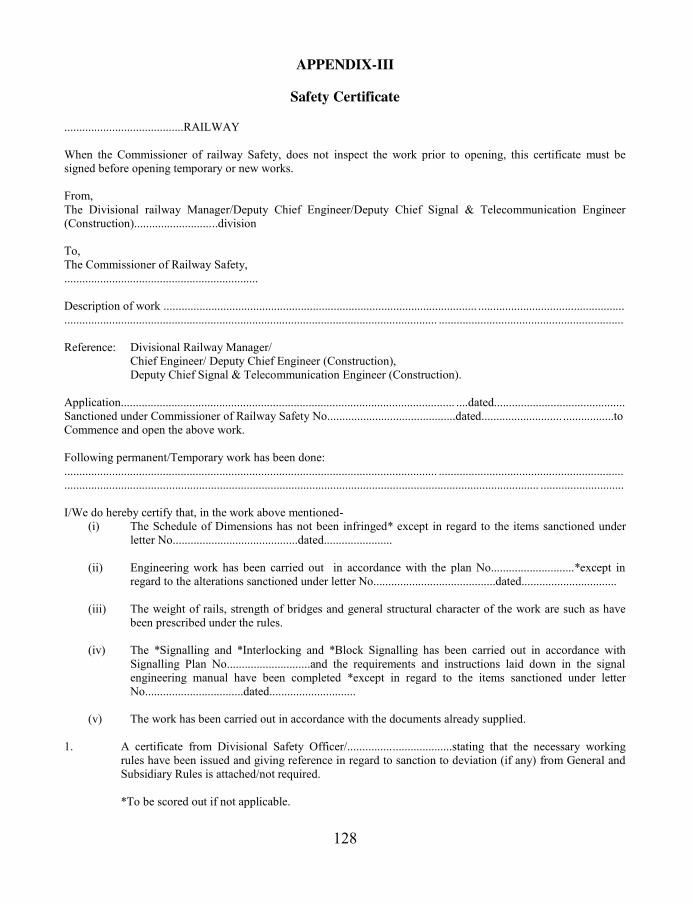
128
APPENDIX-III
Safety Certificate ........................................RAILWAY When the Commissioner of railway Safety, does not inspect the work prior to opening, this certificate must be signed before opening temporary or new works. From, The Divisional railway Manager/Deputy Chief Engineer/Deputy Chief Signal & Telecommunication Engineer (Construction)............................division To, The Commissioner of Railway Safety, ................................................................. Description of work ......................................................................................................... ................................................. ............................................................................................................................. .............................................................. Reference: Divisional Railway Manager/ Chief Engineer/ Deputy Chief Engineer (Construction), Deputy Chief Signal & Telecommunication Engineer (Construction). Application................................................................................................................ ....dated............................................ Sanctioned under Commissioner of Railway Safety No...........................................dated........................... .................to Commence and open the above work. Following permanent/Temporary work has been done: ............................................................................................................................. .............................................................. ............................................................................................................................................................... ............................ I/We do hereby certify that, in the work above mentioned-
(i) The Schedule of Dimensions has not been infringed* except in regard to the items sanctioned under letter No..........................................dated.......................
(ii) Engineering work has been carried out in accordance with the plan No............................*except in regard to the alterations sanctioned under letter No.........................................dated................................
(iii) The weight of rails, strength of bridges and general structural character of the work are such as have
been prescribed under the rules.
(iv) The *Signalling and *Interlocking and *Block Signalling has been carried out in accordance with Signalling Plan No............................and the requirements and instructions laid down in the signal engineering manual have been completed *except in regard to the items sanctioned under letter No.................................dated.............................
(v) The work has been carried out in accordance with the documents already supplied.
1. A certificate from Divisional Safety Officer/...................................stating that the necessary working
rules have been issued and giving reference in regard to sanction to deviation (if any) from General and Subsidiary Rules is attached/not required. *To be scored out if not applicable.

129
2. I/We hereby certify that on the .............................................................20......., I/We have carefully inspected and tested the above work and that I/We have satisfied myself/our self that it has been completed and is in good working order* and that the work can be opened for public carriage of passengers without endangering the safety of the travelling public, or of the employees subject to the following speed restrictions: @Temporary ..........................km p.h................................ .........due to ............................................................. ............................................................................................................................. .............................................. @Permanent............................km p.h........................................due to......................................... ..................... ............................................................................................................. .............................................................
3. The work is being opened on ...................................................................... *Necessary in case of signalling and Interlocking works only. @To be scored out if not applicable.
Countersigned by:
............................................................ .................................................... Assistant Engineer. .................................................... Dated....................................20.......... Dated................................20.......
Countersigned by: ............................................................ .................................................... Assistant Signal and Telecommunication Engineer. .................................................... Dated....................................20.......... Dated................................20.......
............................................................................................................................. .............................................................. No.............................................. Dated............................................. Countersigned and forwarded to Commissioner of Railway Safety for information- 1. 2. 3. 4. 5. Divisional Railway Manager/Chief Engineer (construction)/Deputy Chief Signal and Telecommunication Engineer (construction). ............................................................................................................................. ..............................................................
130
Safety Certificate for S&T works for introducing Electrification It is hereby certified that the Signalling and Interlocking works to be executed for the purpose of introduction of 25KV single phase 50cycles A.C./1500V D.C. traction between....................and ...........................on.......................... Railway have been carried out properly and that the electric traction can be introduced for public carriage of passengers without endangering the safety of the travelling public or of the employees of the railway subject to the maximum value of traction current not exceeding.........Amps. Name: Designation:
*****

131
APPENDIX-IV
FORM VIII
STATION MACHINERY
..........RAILWAY GAUGE: 1.676M
SECTION:LAXMIKANTPUR-KULPI LENGTH: 9.19 km
Nam
e of
Sta
tion
Inte
rlock
ed
Non
-
inte
rlock
ed SIGNALS
Type
of
Blo
ck
In u
se
Way
Bri
dge
No.
&
capac
ity
Isola
ted
War
ner
s/
Dis
tant
Oute
rs
Hom
e
Sta
rter
s
Advan
ced
Sta
rter
s
1 2 3 4 5 6 7 8 9 10 11
Laxmikantpur YES NO - - YES - - YES YES YES Single line Block Instrument
NIL
Udayram Pur NO YES - - - - - - - - - - - - Halt one train only
NIL
Kulpi NO YES - - - - - - - - - - - - Halt one train only
NIL
NOTE: The particulars furnished in this table are illustrative only.
*****

132
APPENDIX-V
List of questions for answers for opening of New Lines or Electrification:
SN QUESTIONS ANSWERS
1 Have the requirements and recommendations for Signalling and Interlocking, and the catechism for signalling and interlocking installations vide chapter VII of these rules, and the appendix thereto, being fully complied with, according to the class of signalling and interlocking installed? If not, in what respect do the arrangements provided fall short of them?
2 Have the requirements and recommendations for Signalling and telecommunication installations in accordance with the instructions issued for the installations of S&T equipment in 25KV 50 Hz electrified sections been complied with? If not, in what respect the arrangements provided fall short of them?
3 Is provision made, whether by trap points or other means, to prevent vehicles standing on sidings, from fouling any running line?
4 Are there any stations situated on a grade steeper than 1 in 400? If so, what special safety devices are adopted and / or special rules enforced at those stations? (No station should be constructed nor should any siding join a passenger line on a grade steeper than 1 in 260, except where it is un avoidable, and then only with previous sanction of the Railway Board obtained through the Commissioner of Railway Safety, when a slip siding or other arrangements are made, sufficient to prevent accidents.)
5 What safety sidings are provided? Are any other necessary? (At any station situated in the immediate neighbourhood of an incline steeper than 1 in 100 falling away from the station and 1 in 80 falling towards the station, a catch siding in former case and a slip siding in later case, should be provided if necessary, in suitable position. The take ‘Off’ points to catch siding or a slip siding should normally be set and locked for the siding except where required to be trailed through.
6 Are station yard so arranged that shunting past junction or level crossings may be avoided as far as feasible?
7 Are shunting necks for goods working provided in large yards, where shunting operations cannot otherwise be carried on without interfering with incoming trains
8 Are means of communication between passengers and the guards provided in all trains carrying passengers?
*****

133
APPENDIX-VI
In case of introduction of new type of locomotive
Joint Safety Certificate
Certified that it is safe to run ..............................(Particulars of locomotives and rolling stock proposed to be run) not exceeding.....................units (in case of locomotives) coupled together on the section (station)................................. to .................. (station) from............................(K.m.) to....................... (K.m.) of the Railway at a maximum speed of......................(Km.p.h.) against a maximum speed of...................(Km.p.h.) certified by R.D.S.O. subject to the following speed restrictions and conditions: (a) Speed Restrictions-
Sl.No. From Km. To Km. Nature of restriction Brief reason for restriction
(b) Special Conditions- ............................................................................................................................. .............................................................. C.M.E. C.E. C.E.E. C.S.T.E. C.O.P.S. Note: (1) When the speed of a loco/rolling stock is to be increased the C.O.P.S. and C.S.T.E. should be associated when the increase in speed is contemplated over the maximum sanctioned speed for that category of train (passenger or Goods over a particular section. (2) C.E.E. should countersign whenever Electric loco is involved.
*****

134
ANNEXURE-VII
Rules for sanction of opening of new railways:
Under Ministry of Railways, (Railway Board), notification 8th October,2000, G.S.R. 762(E), in exercise of powers conferred by sections 28, 29, & 198 of Railway Act 1989 (24 of 1989), the Central Government, made the following rules: 1) i) These rules may be called the (Railway Opening for Public carriage of passengers)
amendment Rules 2001. ii) They shall come into force on the date of their publication in the Official Gazette. 2) In the Railways (Opening for public carriage of passengers) Rules, 2000, in Chapter-II Rule(1), Chapter VI Rule 21(1), 21(2), 21(3), Rule 22(1) and chapter VII Rule 25(2), 25(5) shall be read as follows and Chapter I Rule 1(2), Chapter VI Rule22(2) shall stand deleted. Chapter IV “Sanction to open railway for public carriage of passengers”, of the “Rules for Opening of New Railways or section of a railway for public carriage of passengers” is reproduced as below: Rule- 21. Sanctioning of opening of railway: (1) The Central Government may, after considering the Inspection Report of the Commissioner, confirm, modify or cancel the sanction given under rule 22(1) subject to such conditions, alterations or relaxations as may be necessary. (2) While confirming the opening of any railway, the Central government shall give consideration to the suggestions or conditions subject to which the Commissioner has opened the railway. (3) Where the Commissioner has not recommended the opening of any railway or has proposed to cancel the sanction already given, the Central government shall confirm or modify the recommendation of the Commissioner as necessary and shall direct the Railway Administration concerned to remove the defects or short comings reported by the Commissioner. (4) Where the defects or shortcomings are such that they cannot be removed unless the railway or a portion thereof is dismantled, then the Central Government shall order the closing of railway forthwith for the public carriage of the passengers. (5) Railway line, which is closed for the public carriage of passengers under section 25, shall not be reopened unless it is duly inspected b the Commissioner in advance with the provisions of Chapter IV of these rules and the commissioner recommends the reopening of such railway line. (6) The actual date of opening of a new railway line or a section or a portion of such line for passenger traffic shall be notified by the concerned General Manager, after consulting the Central Government, by notification in the Official Gazette, and in the local news papers of the areas through which the railway line passes.

135
Rule- 22. Opening of railway by Commissioner: (1) The Commissioner, after inspection, may under section 28 sanction the opening for public carriage of passengers of new lines of railway within the respective circles subject to the conditions as the Commissioner may impose. (2) On receipt of the Inspection Report of the Commissioner, the Central Government may confirm, modify or cancel the sanction given under sub-rule (10 subject to such conditions, alterations or relaxations as may be considered necessary. Rule- 23. Sanction to use locomotive engines & rolling stock on new line: (1) The Commissioner may sanction the use of locomotive engines, rolling stock or any other motive power under section 27 which is already running on any zonal Railway, or any division or section of any non-Government railway, or any new lines in accordance with the provisions of Indian Railway (Open Lines) General Rules, 1976 or orders on the subject issued by the Central Government from time to time. (2) Before according sanction under sub-rule (1), the Commissioner shall ascertain that the application of the Indian Railways (Open Lines) General Rules, 1976 by the concerned railway administration which operates the line has been previously sanctioned and notified in the Official Gazette.
*****

136
APPENDIX-VIII List of Infringements of maximum and minimum dimensions:
List of deviations as certified and signed by the General Manager I do hereby certify: i) that the Maximum dimensions for railways in India have in every case been worked to, with the
exceptions detailed in the statement herewith annexed, also that the Standard dimensions will be observed in future, and that no work or structure infringing the standard dimensions will hereafter be permitted without the sanction of the Central Government. (In the statement showing the cases in which the maximum and minimum dimensions have been infringed, full details for each case must be given, in the form given below, with the explanation of the necessity for such infringements and a reference to the authority under which it was permitted. If there have been no infringements of the maximum and minimum dimensions the words “with the exception detailed in the statement herewith annexed” should be omitted or struck out. This form XVII shall be annexed to the certificate)
ii) that each bridge is of such design, dimension and construction as will enable it to bear the dead load of the structure itself (with flooring, roadway, permanent way etc. complete), and in addition thereto, the equivalents of the live loads specified in the rule prescribing Standards of Design and loading for Railway bridges, without exceeding the maximum permissible stress on the available material in any member or portion of the structure.
iii) that more than two engines shall not under any circumstances be allowed at one time on the same track of one span of any bridge.
iv) that every coaching vehicle constructed or procured for the use of the railway in mail and passenger trains is, and shall be provided with vacuum/air brake and effective means of communication between passengers, guard and driver. (This part of certificate is nor necessary for those light lines on which the use of vacuum or air brake has not been insisted upon.)
v) that one compartment or such number of berths or seats, as the railway administration may think fit, of a second class carriage of every train carrying passengers shall be reserved for exclusive use of females.
vi) That the railway shall be worked on the system known as Absolute Block System in accordance with the regulations prescribed in Chapter VIII of the General Rules for railways in India.
vii) that the electric traction equipment can be used for public carriage of passengers without danger to public and that the rules for design and inspection of equipment for electric traction (of Chapter VIII of these rules) have been complied with. (This shall be included only when applicable.)
viii) that the signalling and telecommunication equipment have been installed in accordance with the approved instructions and they are safe for passing traffic.
ix) that……….has been delegated to accompany the Commissioner of Railway Safety on his inspection and all information supplied or engagements entered into by him shall bear my authority.
(Signed) The General Manager
*****

137
APPENDIX- IX
Symbols used for preparation of SIP
Four aspect calling-on signal.
Three aspect slotted starter signal.
Three aspect advance starter signal.
Slotted shunt signal.
Two aspect fog repeater signal.
Traction system dead section indicator.
Banner signal. Point indicator. Junction ind. for use with col light signal.
Signal not in operation.
Signal, the lever of which is locked electrically.
Signal, released by block at ‘line clear’.
Signal, the lever of which is released by token.
Signal, the lever of which is interlocked with key.
Automatic signal.
Semi-automatic signal.
Ground telephone.
Relation of the signal to the track and the direction of traffic.
Block section limit board.
Stop board, calling-on sigg board, absolute block sigg begin etc.
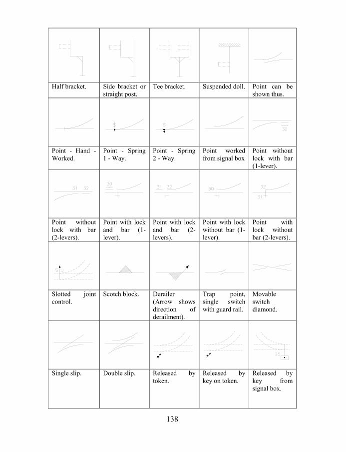
138
Half bracket. Side bracket or straight post.
Tee bracket. Suspended doll. Point can be shown thus.
Point - Hand - Worked.
Point - Spring 1 - Way.
Point - Spring 2 - Way.
Point worked from signal box
Point without lock with bar (1-lever).
Point without lock with bar (2-levers).
Point with lock and bar (1-lever).
Point with lock and bar (2-levers).
Point with lock without bar (1-lever).
Point with lock without bar (2-levers).
Slotted joint control.
Scotch block. Derailer (Arrow shows direction of derailment).
Trap point, single switch with guard rail.
Movable switch diamond.
Single slip. Double slip. Released by token.
Released by key on token.
Released by key from signal box.

139
Insulating rail joint, track circuit in both direction.
Insulating rail joint, track circuit on left, none on right.
Insulating rail joint, track circuit on right, none on left.
Track Circuit portion (single line plans).
Digital axle counter.
Analogue axle counter.
Impedance bond.
Relaying or cut section in track circuit.
Traffic direction.
Over bridge.
*****

140
APPENDIX- X
Track circuit record cards: for DC track circuits, Card Number S&T/TC-1
Card No. S&T/TC-1 .............................Railway
Signal and Telecommunication Department
TRACK CIRCUIT TEST RECORD CARD
1. Station or Section of line 2. Track circuit No. 3. Type of relay 4. Date installed 5. P.U. Volts 6. D.A. Volts 7. P.U. Current 8. D.A. Current 9. Resistance of relay 10. Length of track Circuit (m) 11. Length of Leads from feed end to track (m) 12. Length of leads Relay to Track (m) 13. Type of Ballast 14. Type of Track Feed. 15. Size of track feed conductor 16. Size of conductor to Relay 17. Type of sleeper and condition 18. Type of insulated joints 19. Number of Ash pits in track 20. No. Of L.xings in track 21. Number of insulated joints in Track Ballast Resistance = (VF + VR)/ (IF + IR)
Current at Relay = Voltage at Relay Terminal / Resistance of Relay
22. Date 23. Weather 24. Condition of ballast wet, Damp or Dry 25. Percentage of ballast clear of rails 26. Drainage of track Good, fair or Bad 27. Condition of rail surface 28. Condition of Bonds & Jumpers 29. Condition of insulated joints 30. Condition of Track Battery
Track Feed End
31. Feed resistance 32. Voltage at battery/track feed voltage 33. VF Voltage at rails 34. IF current at rails
Relay End
35. VR Voltage at rails 36. Voltage at Relay Terminals 37. IR current at relay terminals 38. Ballast resistance 39. Rail resistance and Bond resistance 40. Drop shunt value 41. Pickup shunt value 42. Signature of Section Engineer/Signal Signature of Senior Section
Engineer/Signal
Station...........................................
*****

141
APPENDIX-XI
AC Track circuits, Card number S&T/TC-2
Card No. S&T/TC-2 .............................Railway
Signal and Telecommunication Department
TRACK CIRCUIT TEST CARD
2. Station or Section 2. Track circuit No. 3. Type of relay Siemens/Vane type
4. Date installed
5. Frequency: 50/83-1/3 Hz 6. Control phase 7. Local phase 8. Local phase rated P.U. Voltage 9. Control phase rated P.U. Voltage 10. Control phase D.A. Volt 11. Length of track Leads..... (feed end) 12. Resistance of feed end lead 13. Length of track Leads..... (Relay end) 14. Resistance of Relay lead 15. Control P.U. current 16. Control D.A. current 17. Type of sleeper and condition 18. No. of block joints 19. Number of Ash pits 20. No. of Level crossings 21. Length of track circuit 22. Type of Ballast Values for a 50 Hz track circuit Local phase Volt 130B for motor 110V for vane type Local phase current 50A Track phase voltage 18V for motor For vane type Track phase current 0.25A 23. Date 24. Weather 25. Condition of ballast 26. Percentage of ballast clear of rails 27. Drainage of track Good, fair or Bad 28. Condition of rail surface 29. Condition of insulation joints 30. TR Control phase voltage primary 31. Tapping on secondary F/T. 32. VF Voltage feed end rails 33. IF current to track 34. VR Voltage at rails relay end 35. Voltage at Relay Terminals 36. IR current at relay terminals 37. Tapping on primary R/T 38. Tapping Secondary R/T 39. VRS voltage secondary terminals R/T 40. IR Current to Relay terminals 41. VL voltage local 42. Phase angle 43. Ballast resistance 44. Rail resistance 45. drop Shunt value 46. Pick up shunt value 47. Signature of Section Engineer Signal 48. Signature of Senior Section Engineer Signal 49. Station
*****

142
APPENDIX-XII
Jeumont Track circuits, Card number S&T/TC-3 Je
um
on
t ty
pe
trac
k c
ircu
its,
Car
d n
um
ber
S&
T/T
C-3
..
....
....
....
......
....
....
..R
ailw
ay
MA
INT
EN
AN
CE
CA
RD
- JE
UM
ON
T T
RA
CK
CIR
CU
IT
Nam
e of
stat
ion S
ing
le r
ail/
Do
ub
le r
ail
Tra
ck c
ircu
it N
o..
....
....
....
....
Dat
e of
inst
alla
tion..
....
....
....
Tra
nsm
itte
r
(Rel
ay e
nd
co
nn
ecti
ons
(for
double
rai
l tr
ack C
ircu
its)
Imped
ance
, b
on
d f
eed
en
d o
r R
ecei
ver
B
1
B1 N
1
B1
B1
B2
N1
B2
Fee
d e
nd t
ran
sform
er......
R
ecei
ver
ter
min
al
Imped
ance
, b
on
d r
elay
en
d...... B
11
B1
I.B
. te
rmin
als
Rec
eiver
....
...................
Rel
ay..
....
................... A
C
I.
B.
stra
ps
S.N
o.
Dat
e W
eath
er,
dry
or
wet
Su
pp
ly V
olt
age
Imp
uls
es/m
inu
te T
rack
pea
k V
olt
age
(in
Vo
lts)
Tra
ck r
elay
Cu
rren
t T
rain
Sh
un
t
in o
hm
s
F
eed e
nd
R
elay
end
m
a
ma
f
eed
and
Rel
ay e
nd
Note
: tr
ack v
olt
age
to b
e m
easu
red
wit
h i
nte
gra
tor.
This
car
d s
hal
l be
kep
t at
the
rela
y e
nd o
f ea
ch t
rack
cir
cuit
.
*****

143
APPENDIX-XIII Cable insulation Resistance test sheet Main/Tail cables.
Form No. SG/IRC .............................Railway
Station.......................................... Cable insulation Resistance test sheet
Main/Tail* cables
1. Location from....................................................To........................................ 2. Cores..................................................... 3. Size........................................................ 4. Grade 250/440/650/1100V* 5. Length..................................................... 6. Type Unscreened/Screened/Power* 7. Insulation PVC 8. Date of Installation/commissioning........................................... 9. Name of the manufacturer......................................................................
*Strike out which ever is not applicable
Core No. Or Designation Date of Test and whether@
Temperature: Remarks: Signature: @ write wet, damp or dry
*****

Indian Railway Signal Engineering Volume-III
Section-I
SYSTEM OF MECHANICAL SIGNALLING (SINGLE WIRE)

Indian Railway Signal Engineering Volume-III
2
CHAPTER- I
SYSTEM OF MECHANICAL SIGNALLING & SINGLE WIRE SYSTEM
OPERATING DEVICES: DIRECT LEVER LOCKING INTERLOCKING
FRAME
1.0 System of mechanical signalling: System of mechanical signalling is termed as orthodox i.e. “conforming to established views”, which in turn establishes that this system of signalling is basic to present day system of electronic interlocking signalling. Under the system of Single wire signalling, points are operated and locked using levers through rods as media of transmission, signals are operated by levers through single wire as media of transmission, and correspondence of the operation between lever and the point or signal is monitored electrically for signal and mechanically by detector. Interlocking is associated with levers within lever frame withholding pulling of any lever not warranted to be pulled jeopardising safety. The system has been working well with restricted speed of the trains. However with the speed increasing, a faster operating system is required to be introduced, which has emerged with the introduction of electrical and electronic system of interlocking. Systems in use are, i) Single wire and ii) Double wire. Under Single wire system of mechanical signalling i) Direct lever locking interlocking frame to RDSO specification number (SA 530) and ii) Catch handle locking interlocking frame to RDSO specification number (SA 1101) are in use. In addition ground frames are also used for level crossing gate control and local operation of signals and points. Double wire system of mechanical signalling is discussed under Section-II of this book.
1.1 Direct lever locking interlocking frame: Major parts of Direct Lever Locking Interlocking Frame are , i) Lever, Catch Handle, Catch Handle Rod, Number Plate & Catch Handle Box, ii) Quadrants Left Hand, Right Hand, Intermediate under different design and specifications, iii) Quadrant support ‘T’ bar, iv) Standard and ‘Bearing Cap’, v) Brackets, for support of single channel locking box and for support of four channel locking box under different design and specifications, vi) Front Tail for point and signal levers and back tail, under different design and specifications, vii) Lever shoe, viii) Shoe cover, ix) Bearing cap, x) Shaft cap, xi) Shaft collar, xii) Shaft, xiii) Locking Plunger, xiv) locking boxes for 4 channel- 5 levers, 4 channel-7 levers, 1 channel-5 levers and 1 channel-7 levers, xv) Back Weight, xvi) locks of sorts, xvii) Interlocking bars of 16mmx12mm, and xviii) Right End (Cover piece to be provided on right end of the frame).
1.1.1 Lever: Lever, the tool to gain mechanical advantage can be classified in order in which i) fulcrum lies between the load and effort, ii) load lies between the fulcrum and iii) Effort lies between the load and fulcrum. When Load and power impressed on a simple machine keep it in equilibrium, the ratio of the load to power is called as mechanical advantage. Accordingly if the effort arm of the lever of which fulcrum lies between the load and effort, is

3 Pramod P. Goel
longer than the load arm the mechanical advantage shall be greater than unity i.e. operation of signal or point shall be possible to be done by applying lesser effort. The shape of the lever is flat rectangular iron bar with a handle on its top, fastened with lever shoe, with bolts and nuts [Figure 1.1.1 & 1.1.3]. A Catch handle is loosely connected to lever with a pin at the top. A round Lever Handle Rod is held with the Catch Handle, running parallel to the smaller face of the lever up to the quadrants passing through the Catch Handle Box. The catch handle box is fastened with the catch handle rod with nuts adjusted such as to rest on the quadrant with catch handle released due to gravity and to clear the reed of the quadrant on being lifted when catch handle is pressed against lever handle. The Catch Handle Box encases the lever such as to hold the lever in its last operated normal and reveres position when the catch handle is released. As and when it is required to move the lever to either position the catch handle shall be pressed against the lever handle to lift the catch handle box so much so the catch handle box is lifted above the reeds of the quadrant. The portion of the lever between the lever-handle and the shaft on which lever shoe is attached, is the effort arm of the lever. A tail is fixed with the lever shoe with bolts and nuts to which the operated function is attached. The load arm of the lever is the portion of the lever between shaft on which the lever shoe is attached and the tail end. Accordingly lever is from catch handle to tail, running through lever shoe while the shaft is the fulcrum. A number plate is fastened to the lever with nut and bolt to depict the number of the lever. A lever collar is metal plate designed such that when inserted into the lever handle shall not permit the catch handle to be pressed and as such in turn shall not allow the lever to be moved to avoid inadvertent operation of the lever, jeopardising safety. The angular throw of the lever is 270. 1.1.1.1 Slackness permissibility: To accommodate all joints and permissible margins, the Catch Block lifted can move 12 mm (½") on the quadrant reed from the edge, if the interlocking does not permit the operation of the lever. 1.1.2 Quadrants: Part of the effort arm of the lever protrudes above level of the first on which the Cabin Man stands and operates levers while balance part of the lever is below ground level which is housed in the lever shoe and fastened rigidly with it using bolts and nuts. i) Each lever fastened to the lever shoe which is required to be equidistant by providing Shaft Collar on the shaft in between each lever shoe. ii) Same distance between the levers is maintained at the
NUMBER PLATE
LEVER COLLAR
CATCH HANDLE
CATCH HANDLEROD
LEVER HANDLE
PART LEVER Figure1.1.1
Part lever of direct interlocking type
lever frame

Indian Railway Signal Engineering Volume-III
4
first floor level as well to enable the levers move in between equidistant channel created between two quadrants. This maintains each lever, vertical, maintaining equal distance at the lever shoe level as well as at the floor level for maintaining steady movement of the levers. iii) The levers are also required to be held rigidly in last operated position.
3'-218
"
10"
BRACKET (4 CHANNEL)
BRACKET
(SINGLE CHANNEL)
CATCH BOX
F L O O R L E V E L
CATCH HANDLE ROD
CATCH HANDLE
LEVER HANDLE
NUMBER PLATE
LEVER
QUADRANT SUPPORT
'T' BAR
QUADRANT SUPPORT
'T' BAR
LOCKING BOX 4 CHANNEL
LOCKING PLUNGER
LOCKING BOX / CHANNEL
BEARING CAP
Figure 1.1.3 Standard direct interlocking type
Three type of quadrants are used at the ends of lever frame named as i) Quadrant Left Hand and ii) Quadrant Right Hand to close the ends and remaining all iii) Intermediate quadrants to

5 Pramod P. Goel
maintain equal space and a channel to accommodate the lever to move normal to reverse and vice versa. A Quadrant support ‘T’ bar is fixed onto the standards at front and back running parallel to each other to hold all such quadrants fastened with the ‘T’ bar. 1.1.3 Standard: [Figure 1.1.3] Standard made of cast iron is placed and fastened on two steel girders with bolts and nuts absolute right angles to the alignment of girders which is parallel to the side walls of the cabin basement, at interval of 5 or 7 levers in between each pair depending upon type of interlocking box proposed to be used. Accordingly Standards are placed out side first and last levers. The pitch of levers is 125 mm (5"). The steel girders are rigidly placed on cement concrete Bed Blocks which are placed within the side walls of the cabin basement. Stanchions are provided in between both ends of the girder as and where required for support, depending upon span. The ‘T’ bar runs through on top of all the standards to hold quadrants and also help the standard maintain vertical. Brackets for support of four channel locking box are bolted with the front side of the standard and for support of single channel locking box in the rear on space indicated. The shaft, meant to bear the shoe lever runs through all standards end to end and is held in position rigidly by ‘Bearing Cap’ which is fastened at the space provided in the standard as shown in the figure. 1.1.4 Lever shoe: [Figure 1.1.4] Lever shoe is monolithic block with housing for lever, front tail, back tail and arrangement to rest itself on the shaft with the ‘Shoe Cover’ fastened firmly using bolts and nuts, able to rotate about the shaft with the movement of the lever. 1.1.5 Tail: The Front Tail used for signal shall impart stroke as 250mm (9-1/4"), 10-5/8", 300mm (1' 0"), 1' 3/8", 1' 2-3/4" and for points 150 mm (5-7/8") and 200 mm (8"). The stroke to be provided to rod run for operation of points in Broad Gauge (BG) is 200 mm (8") for 125 mm (4½") opening of points.
Back Weight is provided on the Back Tail to assist in withdrawal effort of the wire run while the lever is being put back to normal. Mechanical advantage for 200 mm (8") stroke is 5.4.
SHOE COVER
Figure 1.1.4 (Detail of ‘X’ of figure 1.1.3)
Lever Shoe & Shoe Cover for direct
interlocking frame

Indian Railway Signal Engineering Volume-III
6
1.1.6 Shaft: 50 mm diameter Steel shaft runs across, held rigidly in position, all Standards, by Bearing Cap between first Standard to the last of the lever frame. It holds the lever-shoes for each lever whether spare or in use, provided with ‘Shaft Collars’ to maintain inter lever space. Due to regular movement of the levers there is tendency for the shaft to rotate against pressure of the Bearing Caps due to friction with lever shoe which may cause the shaft to have lateral movement and slip out of its resting position on the end Standards. To secure and keep the shaft from moving laterally Shaft Cap is provided and secured with bolt in its position on standards placed on extreme ends.
1.1.7 Interlocking Arrangement: Interlocking arrangement comprises of the Locking Boxes to bear locks of sorts attached. The Locks are riveted with Interlocking Bars so as to hold or release the locking plunger in conformity to interlocking relation. The Locking Plunger in turn holds or releases the Lever in last operated condition, to which the said plunger is attached.
1.1.7.1 Locking Plunger: Mild steel 16 mm x 50 mm (5/8" x 2") Locking Plunger shall be
supported by rear and front interlocking troughs placed in tappet way, finished to a good sliding fit without any lateral movement, to protrude 100 mm beyond end edges of front and back locking troughs in either position of lever; it is loosely attached with each lever such as to move along with it. Both the edges of such cut section on the plunger are rounded off to accommodate angular movement of the lever. The plunger stroke is 346 mm (13-7/8").
For interlocking purposes notches are cut in the plunger inclined at an angle of 450 to its face, to allow smooth exit of the lock from the notch of the plunger when the plunger is moved to-and-fro against the channels in which Lock is placed for actuating interlocking. ‘Plunger’ is also mentioned as ‘Tappet’ here.
1.1.7.2 Locking boxes: Cast iron Locking Boxes are single channel and four channel fitted on brackets meant for single channel and four channel as per requirement. These brackets are, in turn, fixed onto the standard. The tappet-ways and channels are machine cut to accommodate locking plunger, locks and Interlocking bars. This part of the Locking Box is called as ‘Interlocking Trough”. Under normal conditions single channel locking box is used in rear of the lever frame and four channel locking box on front of the lever frame which falls just below the wooden platform standing on which the lever-man operates the levers. Interlocking arrangements are accommodated in single channel and four channel locking boxes normally on a small yard with end cabins. However channels may be required to be added in multiples of four as and when required to accommodate interlocking more than that what could not be accommodated within first four channels in yard requiring 55/56 levers. In such a situation single channel scheduled to be provided on the rear of the lever frame is replaced by a four channel locking box. Locking Boxes are designed to accommodate five or seven levers. Each such locking box accordingly decides placement of Standards at interval of five or seven levers. The locking

7 Pramod P. Goel
arrangement in this type of interlocking frame is bulky so much so that workability restricts the use up to 55 (5x11) – 56 (7x8) levers warranting to go for catch handle type of lever frame. Pitch of the channels is measured from centre line running across channel to channel and is
110 mm (4-3/8"). Each channel is designed to accommodate three Interlocking Bars running
right angle to the Plunger alignment at the bottom of the channel for which the space kept is 60 mm (2-3/8"). The width at the top of channel is kept as 70 mm (2-7/8") to accommodate three Interlocking Bars running above and across plunger within channel.
1.1.7.3 Locks, Conflicting notches and Interlocking: The Lock has two dimensions, one its overall length to be just fit within the channel of the locking Box and second the lock actuating part which varies from channel to channel. Both combined as one piece is termed as ‘Lock’. With 110 mm channel pitch as against 346 mm stroke the plunger shall cross at least three channels (110 x 3 =330). If the notches in the plunger (tappet) were made of one and the same size each against first two or three channels of the locking trough and all the three channels were provided with different interlocking arrangements, the lock in first channel shall insert into the notch of the plunger and foul the interlocking provided in the first channel while this may also happen with the second or third channel lock. To avoid such a situation to arise, each channel has been prescribed with the size of the ‘Lock’ of each Channel [Figure 1.1.7.3(i)] for locking arrangements in all the three channels interacting with one and the same plunger, in size decreasing from largest size of Lock to the lowest size, for “normal” locking and decreasing sizes for “back locking”; while the corresponding notch in the plunger shall be smallest to interact with the lock in last channel, decreasing upwards to largest, which shall ensure that the largest sized lock in the first channel does not enter into the smallest sized notch in the plunger, true for each other channels. This arrangement of notches takes care of Conflicting Notches. However the said notch in the plunger shall not reach up to last i.e. fourth channel. This calls for use of Locks in channels of sizes different for each channel. Accordingly the locks in the channels ‘A’, ‘B’, ‘C’ & ‘D’ of the trough put on front side of the Lever Frame shall be provided in sizes 1/4th, 2/4th & 3/4th of full size and last being full size. The notch cut into the Locking Plunger is tapered at 450 to the face of the plunger to facilitate smooth exit of the Lock from the notch of the Locking Plunger. Accordingly the size of the Lock is reduced by 12 mm and the Lock face only is measured for all practical purposes. Total length of the Lock being 70mm (2-7/8"), actual dimensions work out to be 15 mm (5/8"), 30 mm (1-1/8"), 40 mm (1-5/8") and 58 mm (2-3/8") corresponding to the channels ‘A’, ‘B’,
Figure 1.1.7.3(i)
Sizes of the Locks and
corresponding Notches

Indian Railway Signal Engineering Volume-III
8
‘C’, & ‘D’ of the trough and the travel of the locking plunger is from Channel ‘A’ to Channel ‘D’. It may be noted that these sizes given here are of that part of the lock which buts against the face of the plunger notch excluding 12 mm component measured parallel to the face of the Locking Plunger in each Lock piece, the portion of the lock inclined at 450 to the face of the lock to match with the notch cut in the plunger to facilitate smooth exit of the lock from the corresponding notch in the plunger [Figure 1.1.7.3(i) & 1.1.7.3(iii)]. As the Locking Plunger shall move forward, the smallest notch in the Locking Plunger shall travel across larger size of the Locks in succeeding Channels reaching to the last Channel, thereby eliminating conflict with the locking. To avoid conflicting notches, while actuating interlocking, it is pertinent to note that in case of
interlocking relation ‘Locks Normal’ the sequence of size of the notches in Locking Plunger
(Tappet), 1/4th of the Lock size, is kept increasing corresponding to first (topmost) channel,
ending on the last channel at full Lock size of notch, keeping the tapered part of the Lock on
upper side of the given channel. While at the same time the locks of sizes decreasing from the
full sized lock to smallest sized lock in the last channel. With the movement of the Locking
Plunger (Tappet) from normal to reverse the notch cut falls within in the Locking Box, moves in
direction from inside Locking Box to tending towards going out of the locking Box along with
the movement of the locking Plunger. It is this movement of the Lock which actuates the
interlocking.
In case of the ‘Requires’ interlocking relation, notch cut in the plunger, has to be out side the
Locking Box, enters into the Locking Box. Accordingly, the sequence of lock sizes and the
direction of the angle/tapered shape of the Locks in the channels shall be reversed starting
from full size lock in first (topmost), decreasing size to lower channels to the last channel to be
1/4th.
As and when the Interlocking Bars with Locks riveted, are placed in the bottom of the channels, Locking Plungers are placed in position, all Interlocking bars are placed on the top of the Locking Plungers, independent Locks not riveted to the Interlocking bars, used by pushers, cannot be put loose into the channel. Such Locks are subject to jump off the position where placed. To ensure this not to happen such locks are riveted to an independent Interlocking Bar large enough to be held under at least two adjoining Locking Plungers where space to accommodate the Interlocking Bar is there and is short enough to remain under for to & fro movement, which shall hold the loose Lock in position or if there is no such space, the interlocking bar shall be riveted with the lock to be at the top. In case the Interlocking bar is on top of the Lock, Cover Brackets are screwed with the body of the trough such as to ensure that the Lock does not jump off the position.
Figure 1.1.7.3(ii) Diamond-
Direct special interlocking
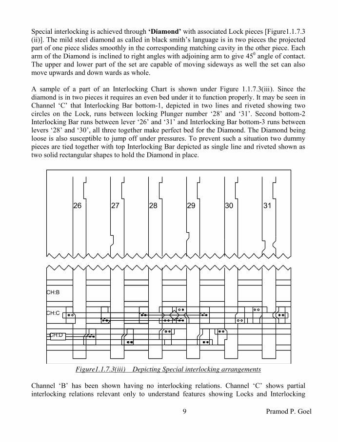
9 Pramod P. Goel
Special interlocking is achieved through ‘Diamond’ with associated Lock pieces [Figure1.1.7.3 (ii)]. The mild steel diamond as called in black smith’s language is in two pieces the projected part of one piece slides smoothly in the corresponding matching cavity in the other piece. Each arm of the Diamond is inclined to right angles with adjoining arm to give 450 angle of contact. The upper and lower part of the set are capable of moving sideways as well the set can also move upwards and down wards as whole. A sample of a part of an Interlocking Chart is shown under Figure 1.1.7.3(iii). Since the diamond is in two pieces it requires an even bed under it to function properly. It may be seen in Channel ‘C’ that Interlocking Bar bottom-1, depicted in two lines and riveted showing two circles on the Lock, runs between locking Plunger number ‘28’ and ‘31’. Second bottom-2 Interlocking Bar runs between lever ‘26’ and ‘31’ and Interlocking Bar bottom-3 runs between levers ‘28’ and ‘30’, all three together make perfect bed for the Diamond. The Diamond being loose is also susceptible to jump off under pressures. To prevent such a situation two dummy pieces are tied together with top Interlocking Bar depicted as single line and riveted shown as two solid rectangular shapes to hold the Diamond in place.
26 27 28 29 30 31
CH:B
CH:C
CH:D
Figure1.1.7.3(iii) Depicting Special interlocking arrangements
Channel ‘B’ has been shown having no interlocking relations. Channel ‘C’ shows partial interlocking relations relevant only to understand features showing Locks and Interlocking

Indian Railway Signal Engineering Volume-III
10
Bars. Two Interlocking relations viz. 26 x 31 either way and Special Interlocking 30 requires 27 when 29 is normal, 30 requires 31 when 29 revered and 30 x 29 either way. As the lever ‘30’ is pulled the Lock attached with bottom-3 Interlocking bar attached to lever ‘30’ shall pull the lock butting with the lever ‘28’ and squeeze the Diamond which in turn shall try to push the Lock connecting other lock with top Interlocking bar-3, into the notch against it but nothing shall happen till the lever ‘27’ is pulled to align its notch against the Lock. As the Lever ‘27’ is pulled first and then the lever ‘30’ is pulled while the lever ‘29’ is normal the Lever ‘27’ shall get locked in reversed position while at the same time the lever ‘29’ also shall get locked in normal position. Similarly when lever ‘29’ is reversed and lever ‘30’ is pulled interlocking shall work only when the lever ‘31’ also has been pulled. In this case also lever ‘30’ shall lock lever ‘31’ as well as lever ‘29’ when all the three levers have been pulled. It may be observed that the lever ‘29’ also gets locked either way. It may be noticed that in this case there is no notch in the lever ‘28’ corresponding to the channel ‘C’ as such there is no interlocking relation with this lever which works as dummy support for actuation of the locking with respect to the present relation in question. To ensure loose locks do not jump off the trough, these Locks are held in position, the lock is riveted in bottom with a piece of Interlocking Bar either end of which is put under the adjoining Locking Plungers, where possible due to availability of space or otherwise by riveting Interlocking Bar on top of the lock or by riveting two Dummy pieces to the Interlocking Bar on each end and putting over the Lock/Diamond as discussed above. After this Cover plates are screwed with Locking Box over such Interlocking bars holding single Lock. 1.1.7.4 Numbering of the channels: Locking Box channels are numbered from top to bottom when looked at the Interlocking Chart, which in effect means numbers start from first channel of rear end locking box to the last channel of the lever frame. Alphabets are used for numbering staring with ‘A’ in capital only. Accordingly rear end Locking Box single channel shall be numbered as ‘A’ which shall continue with front end Locking Box shall be numbered as ‘A’, ‘B’, ‘C’ & ‘D’. More channelled interlocking boxes may be used and numbered accordingly when required. 1.1.7.5 Security of Interlocking against unauthorised interference: The trough is covered by the Cover Plates slid under the Stud Pins fixed on the top of Trough’s side walls through the key holes in the Cover Plate. These Cover Plates covering each trough, placed under the Stud Pins, butting to the end of last Cover Plates with the facing edge of the next Cover Plate from left end to right hand, are terminated by a plate matching to the Cast iron Right End piece attached to the last Locking Box Placed at the extreme right hand. A hole in the cover plate matching the shape and size of the Right End piece and in the Right End Piece accommodates a Cotter Pin through the said hole in the Cover Plate and the Right End piece and sealed by a person authorised to test the interlocking after completion and testing of the Interlocking. The workman ship and the arrangement shall be such that it shall not be possible to open the Cover Plates without removing the seal and the cotter bolt and sliding the cover plates to align the larger orifice part of the key hole, out of the studs. The Left End is 75 mm (2-7/8") long piece
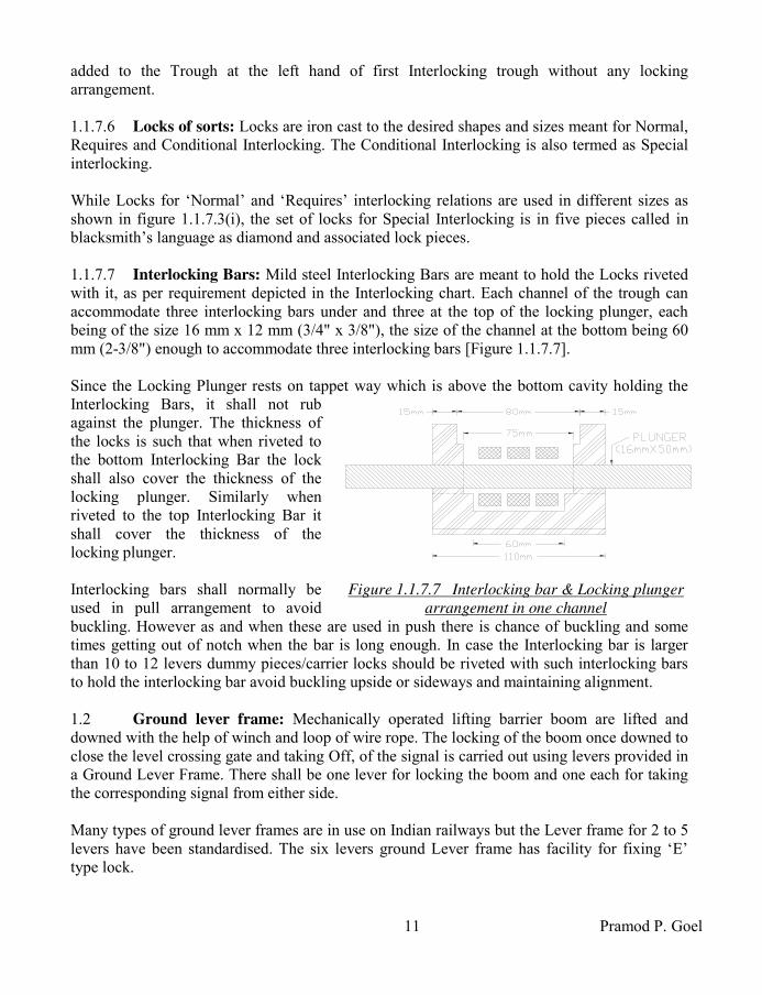
11 Pramod P. Goel
added to the Trough at the left hand of first Interlocking trough without any locking arrangement. 1.1.7.6 Locks of sorts: Locks are iron cast to the desired shapes and sizes meant for Normal, Requires and Conditional Interlocking. The Conditional Interlocking is also termed as Special interlocking. While Locks for ‘Normal’ and ‘Requires’ interlocking relations are used in different sizes as shown in figure 1.1.7.3(i), the set of locks for Special Interlocking is in five pieces called in blacksmith’s language as diamond and associated lock pieces. 1.1.7.7 Interlocking Bars: Mild steel Interlocking Bars are meant to hold the Locks riveted with it, as per requirement depicted in the Interlocking chart. Each channel of the trough can accommodate three interlocking bars under and three at the top of the locking plunger, each being of the size 16 mm x 12 mm (3/4" x 3/8"), the size of the channel at the bottom being 60 mm (2-3/8") enough to accommodate three interlocking bars [Figure 1.1.7.7]. Since the Locking Plunger rests on tappet way which is above the bottom cavity holding the Interlocking Bars, it shall not rub against the plunger. The thickness of the locks is such that when riveted to the bottom Interlocking Bar the lock shall also cover the thickness of the locking plunger. Similarly when riveted to the top Interlocking Bar it shall cover the thickness of the locking plunger. Interlocking bars shall normally be used in pull arrangement to avoid buckling. However as and when these are used in push there is chance of buckling and some times getting out of notch when the bar is long enough. In case the Interlocking bar is larger than 10 to 12 levers dummy pieces/carrier locks should be riveted with such interlocking bars to hold the interlocking bar avoid buckling upside or sideways and maintaining alignment. 1.2 Ground lever frame: Mechanically operated lifting barrier boom are lifted and downed with the help of winch and loop of wire rope. The locking of the boom once downed to close the level crossing gate and taking Off, of the signal is carried out using levers provided in a Ground Lever Frame. There shall be one lever for locking the boom and one each for taking the corresponding signal from either side. Many types of ground lever frames are in use on Indian railways but the Lever frame for 2 to 5 levers have been standardised. The six levers ground Lever frame has facility for fixing ‘E’ type lock.
Figure 1.1.7.7 Interlocking bar & Locking plunger
arrangement in one channel

Indian Railway Signal Engineering Volume-III
12
1.2.1 Main parts of the Ground Lever Frame: Main parts of the Ground Lever Frame
are, i) Number Plate, ii) Standard, Tie Rods, iii) Shaft, iv) Quadrant Left hand, Quadrant right hand, Quadrant Intermediate & Quadrant support, v) Lever Shoe, Lever Shoe Intermediate, vi) Catch Box & Catch Box pin, vii) Plunger & Plunger pin, viii) Lever, ix) Catch Rod, x) Locking Box 4 channels, locking Box 2 Channels, xi) Key lock extension, xii) Catch handle, Catch handle stop, Catch handle pin, Catch handle knuckle and xiii) Shaft Caps. 1.2.1.1 Number Plate: A cast iron number plate is fixed on each lever just below each catch handle depicting the Lever number on its face. 1.2.1.2 Standard & Tie Rods: The Standard is mounted on two iron Channels which are mounted on cast iron foundation, grouted with cement concrete into the ground, maintaining the level almost at ground level such that the lever can be operated standing on the ground. 1.2.1.3 Shaft & Shaft Caps: A Shaft is provided between Standards with shaft caps at the end to avoid slippage of the shaft. 1.2.1.4 Quadrants: Quadrant Left hand, Quadrant Right hand, Quadrant Intermediate & Quadrant Support, are used for guiding and holding the levers in normal or reversed positions. 1.2.1.5 Lever Shoe & front tail: Lever Shoe is not split and is put through shaft. The lever is fastened with the lever shoe with bolts and nuts. Lever Shoe Intermediate holds levers and also maintains 100 mm (4") lever pitch. Front tail for points is for 150 mm (6") and 200 mm (8") strokes. 1.2.1.6 Plunger: The plunger with 277 mm (10-7/8") stroke is connected with the lever through a pin with oblong hole at the point where the Locking Plunger is connected with the Lever, to accommodate Lever’s free radial movement without causing binding with the Locking Plunger. 1.2.1.7 Lever: 1455 mm (4' 9-1/4") long Lever has an angular throw of 520. Lever pitch is 100 mm (4"). Lever is capable of imparting 6" & 200 mm (8") stroke for operated equipment. The mechanical advantage at 200 mm (8") stroke is 6.2, the arrangement being load between effort and fulcrum. 1.2.1.8 Catch Handle: Catch Handle is attached to the Lever with Catch Handle Pin. A Catch Handle Stop limits the distance between Catch Handle and the Lever Handle for lift of the Catch Box and also to prevent from getting the person hurt, while pressing the Catch Handle against the Lever Handle. 1.2.1.9 Catch Rod: Circular mild steel Catch Rod is attached to the Catch Handle through the Catch Handle Knuckle at one end and to the Catch Box through a pin at other end. Catch Box is Cast iron block encasing the lever to hold the lever at normal or reversed position against the reed of the Quadrant when the Catch handle is released. With the lift of the Catch box, it becomes possible to move the lever from normal to reverse and vice versa. 1.2.1.10 Locking Box: Locking Box used with ground lever frame is used for 4 & 2 Channels. The channel pitch is 63.3 mm (2 ½") and width is 55 mm (2-1/8"). Section of Interlocking Bar is 16 mm x 12 mm (5/8" x 1/2"). Two Interlocking bars can be accommodated below the Locking Plunger and three at the top. Locking Boxes shall be for 8 or 10 lever configurations. 1.2.2 Fixing of ground lever frame: Ground Lever Frame is fixed with bolts and nuts on Cast Iron foundations which are grouted into the ground. The frame holds with it the interlocking box, locking plungers and locks to interlock these levers with each other to ensure

13 Pramod P. Goel
that the signal lever is not possible to be reversed until and unless the lifting barrier boom has been locked. Circuit breakers may also be attached to the levers to control colour light signals. Such Lever frames are not intended for operation of semaphore signals as such special arrangements are made for the purpose. The arrangement being, one end of the wire anchored near the lever frame on a pulley stake and the other end carried over a draft wheel, which in turn is fastened with the lever at a point on the lever to impart 200 mm stroke, for operating the signal. However Colour light Signals can be operated using Circuit Breakers connected to the signal lever. 1.3 Use of Double wire system for operating distantly placed signals: Under single wire system of semaphore system of signalling there is no foolproof method for combating the contraction and elongation of wire with the drop and increase of the ambient temperature. As the elongation is proportionate to temperature and the length of the wire, during summers the elongation for distantly placed Warner becomes so much so that almost all the stroke at the lever tail is lost causing the signal to hardly droop. To mitigate such a situation i) double wire levers are used on Catch Handle locking Interlocking frame while ii) another method used is a mix of double wire system with single wire. 1.3.1 Use of Double wire levers on Catch Handle locking Interlocking frame: A support to mount two girders is made of angle irons and fixed with bolts and nuts rigidly on the Standard exactly on the space available for housing Quadrants. On this structure Girders similar to the arrangement for double wire lever frame, are fixed onto which the Double wire lever is mounted. Double wire Direct Lever Crank, operated by the Catch Handle, placed on a vertical Stand which is fixed on the same Girders on which the Standard is mounted, through circular mild steel Catch handle rod, replacing the original Catch handle rod which was meant to be connected to the original Catch handle. The Lever Lock, if required, is also mounted through a lug eye on the bracket fixed on the same girders on which the Double wire lever has been mounted. The crank which is mounted on the stand on the level same as that of Standard, connected to the double wire lever Catch Handle Rod is in turn connected to the locking plunger of the Locking Box common to other levers. The entire arrangement is such that the throw of the locking plunger connected to the Double wire lever is same as those of other Single wire levers operated by the same Lever frame on which the double wire lever is mounted to work Warner signal. The wire transmission for such double wire lever is same as that of in case of double wire system of signalling to be discussed in section-II of this book. 1.3.2 Mix of double wire system with Direct Interlocking lever: Facility of back tail not being available with Catch handle interlocking lever, it shall not be possible to use the arrangement. The front and back tails are used to hold one wheel each. A wire loop is connected to the double wire signal machine through double wire compensators. For details of transmission refer to Section-II (double Wire System of Signalling) of this book.

Indian Railway Signal Engineering Volume-III
14
The wheels are hung at 10" stroke position of front and back Tails. One end of the wire run is fixed rigidly below, onto the ground mounted on the base and guide which in turn are fixed on Cast iron foundations rigidly grouted with the cement concrete into the earth, made to pass through the wheels of the Lever Tail vertical wheels. The wire loop passes through the double wire compensators and lastly wrapped around the signal machine. With the pulling of the lever, the wire on front tail shall be pulled simultaneously releasing equal length on the back tail wheel thereby giving rotary movement to the signal machine. The signal machine shall get reverse rotary movement on putting the lever back to normal. Since the wheel is attached to the Tail at 10" stroke, the total pull shall be double the stroke i.e. 20" as required for the signal machine to rotate complete.
*****

15 Pramod P. Goel
CHAPTER- II
SINGLE WIRE SYSTEM OPERATING DEVICES: CATCH HANDLE
LOCKING TYPE INTERLOCKING FRAME
2.0 Catch Handle locking interlocking frame: Catch Handle Type Lever Frame to RDSO specifications SA1101 has major deviation to the Direct Type Of Lever Frame being i) the locking is actuated directly by pressing of the catch handle against Direct type where the locking is actuated by operation of the lever and ii) the locking trough is inclined to 300 to vertical thereby facilitating convenient inspection and working on the Trough.
2.1 Main parts of the Interlocking frame: Main parts of the Interlocking frame are: i) Lever, ii) Number Plate, iii) Catch Handle, Catch handle stop, Catch handle pin, Catch handle knuckle, iv) Catch Handle rod, Catch Handle Lug, Catch Handle spring & Catch Handle box, v) standard, vi) Quadrant Left Hand, Quadrant Right Hand, Quadrant intermediate & Quadrant support, vii) bearing Cap, viii) End Shaft cap, ix) Plunger guide, x) Shaft, xi) Lever Shoe, Lever Shoe Left hand, Lever Shoe Right hand & Lever Shoe Intermediate, xii) Link Pin-1 & Link Pin-2, xiii) Link ‘A’ & link ‘B’, xiv) Locking Box six channel A & B, Locking Box eight channel A & B, Locking Box ten channel, xv) Locks, xvi) Interlocking bar. 2.1.1 Lever: The 2275 mm (6' 6") mild steel Lever measured from top of the Lever Handle up to centre of Shaft, is fastened with the Lever Shoe using bolts and nuts. The Lever has an angular throw of 330. The ‘Tail’ is an extension of the lever itself as against direct locking Interlocking frame where the ‘Tail’ is an independent piece; as such there is no back tail. Stroke for signals in this case is also 250 mm (10") and 300 mm (12"), and strokes for the point are 125 mm (4-5/8"), 150 mm (6") & 200 mm (8"). Mechanical advantage of this lever is 5.6 at 200 mm stroke. A number plate is fastened with nut and bolt, to the lever near Catch handle. 2.1.1.1 Slackness permissibility: To accommodate all joints and permissible margins, the Catch Block shall not be lifted more than 3 mm (1/8") above top of quadrant, if the interlocking does not permit the operation of the lever. However when the locking permits operation of the lever the lift of the Catch Block must not be less than 20 mm (¾"). 2.1.2 Catch Handle: [Figure 2.1.2] The Catch Handle is attached through a pin near handle of the lever. It has a stop to restrict the movement of the Catch Handle such that the lift of the Catch Block just clears the reed of the Quadrant, as well as at the same time it does not hurt the person while pressing against Lever Handle.

Indian Railway Signal Engineering Volume-III
16
A circular Catch Handle Rod connected with the Knuckle is connected to the Catch Handle through a pin. This Catch handle rod is one piece starting from the Catch Handle and ending where Link ‘A’ is connected. The Catch Handle Box is fastened with the lever with bolts and nuts, loaded with a spring, through which the Catch Handle Rod passes held by a stud to compress the spring, such that the Catch Handle shall return back to its open condition on release by the operator. The Catch Handle Rod shaped by smithy, just after the Catch Box, the Catch Block to rest on the Quadrant when the Catch Handle is open. The Catch Rod Lug is held with nuts & check-nuts at the threaded end of the Catch Handle Rod, the arrangement being to facilitate adjustments of Link ‘A’ & Link ‘B’ for interlocking. 2.1.3 Standard: [Figure 2.1.3] Standard made of cast iron is different to direct type in shape and design to bear all the Interlocking Boxes on one side of the standard, placed inclined to vertical by 330. Standard is placed and fastened on two steel girders with bolts and nuts absolute right angles to the alignment of girders which is parallel to the side walls of the cabin basement, at an interval of 8 or 10 levers in between each pair depending upon type of interlocking box proposed to be used. Accordingly Standards are placed as out side first and last levers.
CATCH
HANDLE
LEVER HANDLE
NUMBER PLATE
STOP
KNUCKLE
CATCH
HANDLE ROD
SPRING CATCH HANDLE BOX
QUADRENT
L E V E LF L O O R
LOCKING BOX
(6 OR 8 CHANNEL)
INTERLOCKING BAR
LOCKING PLUNGER
BEARING CAP
45 8"
6"8"
10"
12"
CATCH ROD LUGSTANDARD
LEVER
SHOE COVER
PIVOT
LINK 'B'
33°
27°
LINK 'A'
LEVER SHOE
Figure 2.1.3 Standard -Catch Handle Locking

17 Pramod P. Goel
The steel girders are rigidly placed on cement concrete Bed Blocks which are placed within the side walls of the cabin basement. Stanchions are provided in between both ends of the girder as and where required for support, depending upon span. The ‘T’ bar runs through on top of all the standards to hold quadrants and also to help the standard maintain it vertical. Brackets for support of four channel locking box are bolted with the front side of the standard and for support of single channel locking box in the rear on space indicated. The Shaft, meant to bear the Lever Shoe runs through all standards end to end and is held in position rigidly by ‘Bearing Cap’ which is fastened at the space provided in the standard as shown in the figure. 2.1.4 Quadrants: Quadrant Left Hand is designed to close space on the left hand side of the first lever while Quadrant Right Hand is designed to close space on right hand side of the last lever. Quadrant Intermediate is used in between all other levers to provide slot for moment of the lever. Catch Block holds the lever in its normal or reverse position as the case may be, held against reed of the Quadrant, when the Catch Handle is open. It shall be possible to move the lever from normal to reverse and vice versa, as and when the Catch Block is lifted above reed of the Quadrant, due to pressing of the Catch Handle against Lever Handle. It is pertinent to note that in case of Catch Handle locking interlocking frame, the Catch Block shall be lifted above reed of the Quadrant only when locking permits so. Two ‘T’ Bars run parallel across all the standards end to end fixed on front and back supports of each Standard. The Quadrants are placed side by side covering space between the Standards, closed by end quadrants on both ends of the lever frame, bolted on both ‘T’ Bars termed as Quadrant Supports. 2.1.5 Lever Shoe: [Figure 2.1.5] Lever Shoe is fastened with the lever through bolts and nuts. Lever shoe cover, the other part, is attached to the Lever Shoe through bolts and nuts encasing the shaft. Unlike Shaft Collars used with direct Interlocking frame, the arrangement to maintain desired space is inbuilt in the Lever Shoe.
Figure 2.1.5
Lever Shoe- Catch Handle locking

Indian Railway Signal Engineering Volume-III
18
Accordingly Left hand Lever Shoe is used on extreme left hand lever, Right Hand Lever Shoe on extreme Right hand lever and Intermediate Lever Shoes are used on all levers other than extreme left and extreme right hand levers to maintain inter lever pitch of 100 mm (4"). 2.1.6 Shaft: Steel Lever shaft of 50 mm diameter runs across and is held rigidly in position at each Standard by Bearing Cap between first Standard to the last of the lever frame. Shaft holds the Lever Shoes for each lever whether spare or in use. Due to regular movement of the levers there is tendency for the shaft to rotate against pressure of the Lever Shoe Cover, due to friction with Lever Shoe which may cause the shaft to have lateral movement and slip out of its resting position on the end Standards. To secure and keep the shaft from moving laterally End
Shaft Cap is provided and secured with bolts in its position on Standards placed on extreme ends. Shaft shall be one piece between any two Standards but may not be single piece across Standard, first to last. 2.1.7 Interlocking Arrangement: Interlocking arrangement comprises of the Locking Boxes to bear Locks of sorts, Interlocking Bars and the Locking Plunger. The Locks are riveted with Interlocking Bars so as to hold or release the locking plunger in conformity to Interlocking Chart. The Locking Plunger in turn holds the Catch Handle from being lifted above Quadrant reeds or releases the Catch Handle there by allowing the Catch Handle being lifted, Catch Block being lifted above reed of the quadrant and consequently lever being operated. A pair of wrought iron Link ‘A’ moves about pivot, provided on both sides of the lever, is attached to Catch Rod Lug, at one end and to the short malleable cast iron Link ‘B’. The other end of the link ‘B’ is connected to the Locking Plunger through pin. The link ‘B’ is sandwiched between both pieces of link ‘A’. The Chanel pitch is 55mm (2-1/16"). See figure 2.1.7 for interlocking arrangements. The figure is in three pieces cut through oblique lines, to accommodate relevant portion to be discussed, from a large size Interlocking Chart taken as example. Vertical parallel strips depict Locking plungers numbered as 8, 9, 10, 11, 15 & 19. Horizontal strips depict channels numbered as CH: ‘C’, CH: ‘D’& CH: ‘E’. Interlocking bars running on the top of the Locking Plunger are depicted through single line by the upper out side of the channel as top interlocking bar-1 and running on the lower side out side of the channel as top Interlocking bar-2. Similarly Interlocking Bar running under the locking plunger shown on the upper side within the channel is interlocking bar-1 and Interlocking Bar running under the locking plunger shown on the lower side within the channel is interlocking bar-2. 2.1.7.1 Locking boxes: Locking Boxes used with Catch handle Locking Interlocking frame are designed for six channels, eight channels and ten channels each of which having eight or ten Tappet Ways to accommodate eight or ten Locking Plungers. The cast iron locking box is machine cut to make Channels and the Tappet Ways to the size to accommodate Interlocking assembly and the Plungers in the form of the Locking Trough. Width of the channel is 40 mm (1-17/32").

19 Pramod P. Goel
MS flat Plunger Guides are bolted on both ends of channel box held by bolts with the side walls of the trough, to hold the Locking Plungers in position. When more than 10 channels are required to be used two or more locking boxes are secured one below the other on two angle irons, one on each side of the locking box, and then whole assembly along with two angle irons, is fixed onto the standard’s brackets.
Figure 2.1.7 Interlocking Chart important features 2.1.7.2 Locking Plunger: The Locking Plunger of dimensions 40.90 mm x 10 mm (1-3/4" x 3/8") has a net stroke of 65 mm (2-15/32"). This stroke is more than the channel pitch of 55mm (2-1/16") as such cutting of notches in the Locking Plunger becomes critical and are required to be done judiciously to avoid conflicting notches. ‘Plunger’ is also mentioned as ‘Tappet’. i) Actuation of the locking Plunger: Actuation of the Locking Plunger is special feature of Catch Handle Interlocking Frame as against Direct Interlocking Frame. As the Catch Handle is pressed against the lever handle, the Catch Rod Lug is lifted if the locking permits so. With the Catch Rod Lug getting lifted, the end of the Link ‘A’ connected to the Lug also gets lifted in turn pressing the other end of the Links about the pivot, to which the Link ‘B’ is connected which in turn imparts forward stroke of 31 mm (1-3/32") to the locking Plunger. As the Lever is moved from normal to reverse position the Locking Plunger first gets another forward stroke of 10 mm (3/8") and thereafter a backwards stroke of 7 mm (9/32") resulting in a net stroke of 3mm, during the lever being put from normal to reverse from press of Catch Handle with start and release of Catch Handle with Completion of the movement. As the catch handle is released the Locking Plunger moves further by 31 mm (1-9/32") resulting in a net

Indian Railway Signal Engineering Volume-III
20
forward stroke to the locking plunger as 65 mm (2-15/32"). The actuation of the Locking Plunger is same but in reversed sequence with the same stroke when lever is put to normal. 2.1.7.3 Locks of sorts & Interlocking: Locks for normal locking are iron cast to the desired shapes and size shall be same as to conform to the channel width. Locks and Slips required for conditional interlocking are specially designed to meet with the given requirement. Conditional Interlocking is also termed as Special Interlocking. The ‘Slip’ a metal plate with two slots parallel to each other is held by two square headed studs screwed onto the Locking Plunger number ‘11’ [Figure 2.1.7] such that the metal plate slides freely between both slots end to end. In such a situation the Lock is designed with an undercut so that it pushes only the slide plate without direct relation with Locking Plunger. Such undercut Lock is depicted with a dotted horizontal line just above the cut. The protruded part of undercut Lock moves in to push the slide imparting idle movement of the lower undercut part of the lock [Figure 2.1.7.3(i)]. Small slip may also work with single square headed stud. Normal Locks such as locks against plunger number ‘9’, ‘15’ and ‘19’ are of full size accordingly the notch is cut in the Locking Plunger to match the shape and size of the Lock. In this example the Interlocking relation is ‘19’ requires ‘15’ when ‘11’ is normal and ‘19’ requires ‘9’ when ‘11’ is reversed. The Slide is cut with half notches on both ends of interlocking face. Two pieces of locks put side by side are used to realise the special interlocking relation. As when the lever ‘19’ is pulled with lever ‘11’ normal, the Undercut Full Lock piece [Figure 2.1.7.3(ii)], with full width protruding and butting against the Slide is pulled (the Interlocking bar being in tension) thereby pushing the Slide which in turn tries to push the undercut lock, which shall not move as the notch in the Lever ‘15’ is not available to accommodate the Lock which is tied with the Undercut Lock through Interlocking Bar (Interlocking bar in this case gets in compression). As the lever ‘19’ is pulled keeping lever ‘11’ normal, after pulling the lever ‘15’ the Lever ‘15’ gets locked in reverse position as the notch in the lever reaches opposite the Lock. The other relation ‘19’ requires ‘9’ when ‘11’ reversed is achieved similarly by pulling lever ‘19’ after levers ‘11’ and ‘9’ having been pulled. It is pertinent to note that there is no relation when the desired condition is not fulfilled such as when lever ‘11’ is normal there is no relation between lever ‘19’ and lever ‘9’, similarly there is no relation between lever ‘19’ and lever ‘15’ when lever ‘11’ is pulled.
Figure 2.1.7.3(i) Undercut
Lock for special locking
Figure 2.1.7.3(ii) Undercut Full
Lock for Special locking

21 Pramod P. Goel
2.1.8.4 Interlocking bars: Mild steel Interlocking Bars are meant to hold the Locks riveted with it, as per requirement depicted in the Interlocking Chart. Each channel of the trough can accommodate two Interlocking Bars under and two at the top of the Locking Plunger, section of each Interlocking Bars being 16 mm x 12 mm (5/8" x 1/2"), the size of the channel at the bottom being 60 mm (1-3/8") is enough to accommodate two Interlocking Bars below the Locking plunger. 2.1.8 Numbering of the channels: As the Locking Boxes are fixed on front of the Lever Frame, channels are numbered from top to bottom when looked at the Interlocking Chart, which in effect means numbers start from first channel of the locking box to the last channel of the last Locking Box. Alphabets are used for numbering channels, staring with ‘A’ in capital only. Accordingly Locking Box channels shall be numbered as ‘A’, ‘B’, ‘C’, ‘D’, ‘E’, ‘F’, ‘G’ & ‘H’. The numbers of the Channels shall continue in same series from ‘I’, ‘J’, ‘K’ and so on, if another Locking box is added to the first one. There is no limit for extension of the channels. The locking plungers are numbered same as that of corresponding levers. 2.1.9 Security of Interlocking against unauthorised interference: The trough is covered by the Cover Plates in style same as that of Direct Locking Interlocking frame and held in position by cotter-bolted and sealed.
*****

Indian Railway Signal Engineering Volume-III
22
CHAPTER- III
TRANSMISSION
3.0 Media of transmission: Under signalling system of single wire the media of transmission between lever and the signal is wire run and for operation of points it is rod run. The wire run is a mix of Galvanised Iron (GI) wire for straight run and wire rope to take diversion on the horizontal/vertical wheels, connected to the Tail of the Lever, to the vertical wheel which is fixed on the Lead-in within cabin and taken out of the cabin to lead Out on Horizontal Rope Wheels and then run up to the signal concerned carried on the pulleys and Horizontal Rope Wheels, passing parallel and across under the railway track to reach up to vertical wheel/wheel mounted near or on the signal post, and attached to the counter weight bar mounted on the signal post. For rod run the rod is connected to the Lever Tail at one end to the arm of Vertical crank mounted on the Lead-in at other end. The next rod is connected to the other arm of the vertical crank, taken out of the cabin and connected to one arm of the Accommodating crank mounted at the out side lead-out. One end of another rod is connected to the other arm of the Accommodating Crank on the out side lead-out. The rod runs further put on Trestles, through rod Compensators, taking diversions in the route through equal arm Horizontal Cranks passing under and across the railway track terminating at the Adjustable Crank to connect the point or Facing point lock or the Lock bar, as the case may be. 3.1 Lead-out: Wire or rod run is connected to the Lever Tail which is at height from the ground floor inside basement to be lead up to ground level and then all such vertical transmissions imparted by the Levers are converted into horizontal transmissions through Vertical Rope wheel in case of wire run and through Vertical Crank in case of rod run. The point falling just below the Lever Tail to convert the vertical transmission into horizontal transmission is termed as ‘Inside Lead-out’. Further more, such converted horizontal transmissions are also to be taken out of the cabin basement to be distributed to either side of the cabin, to be connected the to the Signals, Points, Locks And Lock Bars. At this point of diversion the transmission takes direction on either side of the cabin, right angles to the transmission coming out from the cabin Inside Lead Out. The point at which the diversion and distribution of wire run and the rod run takes place is termed as Outside Lead-out.
Figure 3.1(i) Equipment needed for wire run & inside lead-out

23 Pramod P. Goel
Vertical cranks and wheels may be fixed on i) MS plates or onto ii) Channel iron at the lead-out. i) Lead-out Plates: The plates are chosen of size convenient to be handled by two persons easily. Some railways use 16 mm (5/8") thick plates of the size 1000 mm x 60 mm (3'4" x 2'). Girders are placed spaced at 1000 mm onto which the plates are placed butting each other along the web of the girder and riveted with the girder using 16 mm x 37 mm (5/8" x 1-1/2") cup-headed steel rivets countersunk on top. The girder is fixed on to the cast iron foundation rigidly grouted into the ground with sand, cement and gravel aggregate. Accordingly the connection of rod with vertical crank at the inside lead-out shall be absolute right angles when the arm of the vertical crank to which the rod is connected is absolute vertical.
Maintaining level between inside lead-out and inside lead-out of the foundation plate is of utmost importance to be kept same and horizontal. It shall be ensured that the level of the rod run beyond out side lead out also remains same as that of out side Lead-out. However in case there is any restriction on maintaining the rod run absolutely horizontal, the rod shall be lead forward after getting connected to the Accommodating Crank by making offset in all the rods. If three accommodating cranks are provided on outside lead-out the rod shall be connected to the medium crank straight while the rod connected to the high crank and other to the low crank shall be connected to the high crank and low crank by providing 60 mm (2-1/2") offset upside and low side respectively.
It is pertinent to note that any slope in the rod run shall cause operation of the lever extremely
heavy due to tendency of the rod being sliding downwards or upwards.
ii) Channel Iron Lead-out: Channel Iron is used by some of the railways to fix vertical cranks and vertical rope wheels. These Channel irons are place parallel to the lever frame out side the cabin basement levelled with in side Lead-out and out side wire and rod run with reference to rail level. These Channel irons are fastened firmly with the cast iron foundations which are embedded into ground and grouted with sand, cement and gravel aggregate. While vertical cranks are fixed on the Channel Iron, the horizontal rope wheels are fixed on independent cast iron foundations inside cabin. However outside cabin these horizontal wheels are mounted on Mild Steel plates supported onto the cast iron foundations, to form an array such that the wire run takes off keeping adequate separation to avoid joints entangling with each other while running parallel to the track. It is pertinent to note that any movement of the Inside Lead-out girder or outside lead-out shall
render complete failure of all operations from the cabin concerned which shall be possible only
by non-interlocking the cabin for the period to settle the castings.
3.1.1 Inside Lead-out: Inside lead out is required for leading the wire and the rod run within cabin connecting with the levers and leading out to the outside lead-out.

Indian Railway Signal Engineering Volume-III
24
i) Inside Lead-out for wire run: Two Girders run across the cabin running parallel to the girders which bear the Standards, just below the Lever Tail where the rod for Point, Lock and Lock Bar operation is connected such that the hole in the arm of the Vertical Crank is in exact alignment of the rod hanging free from the lever tail. The rod is connected to the arm of the vertical crank with the arm positioned 100 mm above the level of horizontal line running through the axle of the crank. The Girder ends are fastened with end walls of the cabin basement as well as are firmly held with bolts and nuts with cast iron foundations grouted with sand cement and aggregate into the ground at suitable intervals to ensure that the girders do not allow any movement to the Vertical Cranks. The Vertical Rope wheels are mounted on the Inside Lead-out for wire transmission. Obviously the wire connected to the Lever tail shall not be exactly vertical having been connected at the Lever Tail for greater stroke.
Accordingly a Shackle is connected to Lever Tail hole suitable for desired stroke to the concerned signal. The piece of GI wire is terminated on Thimbles, connected with the Shackle at one end and Wire adjusting Screw at the other end, through Split Links. The other end of the Wire Adjusting Screw is connected to the Wire Rope Sling through Split Link. The wire rope sling passes over Vertical Rope Wheel on Inside Lead-out and connected with the GI wire to be taken out of cabin basement [Figure 3.1.1(i)]. The GI wire is run and connected to the wire rope. This wire rope runs around one way, two way or three way horizontal wheels, as per requirement, fixed on the outside Lead-out to change the direction of wire run. In area provided with 25 KV AC traction all such wires leading in to the cabin basement shall be provided with wire insulators using split links and Thimbles, before the out side lead-out to ensure that the wire touching rails here and there, do not transmit the electric current to the lever frame, harming the operator by the electric shock.

25 Pramod P. Goel
ii) Inside Lead-out for Rod run: Vertical cranks are fixed directly with bolts and nuts on the Channel iron running parallel to the lever frame which is fixed with bolts and nuts with the cast iron Foundations grouted with sand, cement and gravel aggregate, into the ground. In case of the other method by using MS plates, the Channel irons are fixed right angles to the alignment of lever frame leading from inside cabin from the point of inside lead-out to beyond out side cabin up to the point of out side lead-out spaced such that to accommodate the MS plates butting each other along the web of the channel, fastened with bolts and nuts with counter sunk head. The vertical cranks are fixed on the channel iron or the MS plate as the case may be such that the arm of the crank to be connected with down rod hanging from the lever tail, is kept down below the horizontal position by 100 mm so as the arm goes 100 mm above the horizontal position of the arm of the crank to ensure that the movement of the arm of the crank is equal on either side of the horizontal line running across centre of the hub of the crank when operated by the lever for 200 mm stroke. It is pertinent to note that there is no provision fro adjustment in the down rod which is connected to the lever Tail and the arm of the vertical crank through Solid Joints. The down rod shall have no offsets. The other arm of the vertical crank is also connected to the rod through Solid Joint. The solid joint has either butt end or coupling end. In this case the solid joint with coupling end shall be used. Each standard point rod is provided with a coupling joint at its both ends. The rod is connected between the other arm of the Vertical crank and the accommodating crank at the outside lead-out. The rod shall be connected straight to the arm of the Medium crank while an 60 mm (2-1/2") up wards offset shall be given in the rod to connect it with high crank and similar downward offset shall be given to the low crank to match the difference in heights of these cranks at the out side lead-out. The rod inside cabin basement running between inside lead-out and out side lead-out shall be supported onto the Standard Roller Guides which is fastened with the bolts and nuts to the Trestles embedded into the ground rammed properly to ensure no movement. In area provided with 25 KV AC traction all such rods leading out of the cabin basement shall be provided with Rod Insulation, before the out side lead-out, which shall be with butt end or coupling end. It is preferable to provide coupling end Rod Insulation to facilitate replacement in case of damage without going for smithy work. 3.1.1.2 Out side Lead-out: Outside lead-out is to connect the wire and the rod run leading out of the cabin, to be connected with the Signal, Point, Facing point locks and Lock bars. i) Out side Lead-out for wire run: As the GI wire leads out of the cabin basement it is required to be diverted on either side of the cabin using Horizontal wheels further to be connected to the signals concerned running on pulleys which are hung on pulley stakes or gantries. While the space interval (pitch) of 100 mm (4") or 125 mm (5") of the Vertical Rope Wheels depends upon the type of the lever frame used, the Horizontal two way wheels shall be

Indian Railway Signal Engineering Volume-III
26
mounted at the Out side Lead-out MS plate or the cast iron foundation, to match pitch of the levers maintaining wire run straight and parallel to each other. The alignment of the wire run beyond outside lead-out shall be such as to maintain separation between the wires beyond outside Lead-out. As the bracket of the pulley has two holes apart by 2¼" it is fixed onto the pulley Stake through these two holes, while next pulley is fixed below the upper pulley onto by next hole 1½" below for second pulley. Horizontal three way wheels shall not be used on Outside Lead-out. The base of the Horizontal rope wheel shall be fixed keeping inclined by 450 to the cabin wall so as to equalise force on the bolts used for fixing the base. The joints between wire rope and the GI wire beyond the out side lead-out and between the Stud Pin of the two way horizontal wheel and the nearest joint shall be maintained at minimum separation of 2'6" to avoid entanglement with wires of other signal, in case of breakage of the wire. [Figure 3.1.1.2 (i)]
The Horizontal wheels are available in one way, two way and three way, each wheel mounted on the central stud pin fixed on the cast iron base. Two other stud pins are riveted on to either side and in alignment of the central stud pin. The wheel base has four holes for fastening it with MS plate, keeping the head of the bolt underneath plate so as to keep a watch on the tightness of the bolts and nuts. To prevent from the wheel coming out of the central stud pin, a top strap (steel plate) is put through all the three stud pins and secured. ii) Out side Lead-out for rod run: Accommodating Crank shall be fixed on MS plates such that the rod leading out of the inside lead-out, connected to the curved arm of the crank maintains separation of 118 mm (4.7") for 100 mm (4") lever pitch or 140 mm (5.5") for 125 mm (5") lever pitch, between rods. The rods run connected to arm of the crank which is straight, shall maintain a separation of 60 mm (2-1/2") between each other according to which the trestles have been designed to bear upon the Standard Roller Guide.
2'-6" 2'-6" 2'-6"
WIRE ROPES
1 WAY HORIZONTAL ROPE WHEEL
2 WAY HORIZONTAL ROPE WHEEL
Figure 3.1.1.2 (i) Outside Lead-out for wire run

27 Pramod P. Goel
Accommodating cranks, accordingly, are designed with arms 300 mm x 300 mm (12" x 12") and 350 mm x 350 mm (14" x 14") for 100 mm and 125 mm liver pitch respectively with low, medium and high bases. [Figure 3.1.1.2 (ii)]. To obtain the given requirement, the MS plates on which the accommodating Cranks shall be fixed, the foundation plate shall be placed angular with reference to the cabin wall. The base of the accommodating cranks shall be squarely placed along centre line of plate. The solid joint with coupling end shall be connected to the straight arm of the crank for extending rod run further into the yard. 3.2 Wire Run: When ever the Galvanised Iron (GI) wire and Wire Rope are required to be joined with Adjusting Screw or of any other equipment, both ends of the wire concerned shall be terminated on Thimble and twisted/held such that there is no scope left for failure of joint due to improper twisting/holding. Whenever one wire is required to be connected with another wire or an Adjusting Screw or with any other devise, these shall be coupled invariably using a Split Link in between the two, in the wire run; to make connecting and disconnecting easy to replace the defective wire piece or the Adjusting Screw within minimum interruption to the signalling system/train movement. Any wire joint in the run shall be kept at least 6' (1800 mm) away from the nearest pulley. The Wire Adjusting Screw is provided in each signal transmission of length less than 300metres (1000 feet), between the Lever Tail of the signal concerned and the vertical rope wheel at the inside lead-out. The 450 mm (1.5') long turn buckle of the Wire Adjusting Screw has 12 mm (½") rods threaded inverted such that turning of the turn buckle shall cause closing or releasing of the wire [Figure 3.2].
4.7
" OR
5.6
"FROM INSIDE LEAD OUT OF THE CABIN
Figure 3.1.1.2 (ii) Out side lead-out rod run
Figure 3.2 Wire adjusting screw

Indian Railway Signal Engineering Volume-III
28
The wire, after taking off from the lever tail, passing through the inside lead-out and outside lead-out, shall be carried onto the wire pulleys flat or swing, fastened with the pulley stakes, crossing the track as and when needed, passing through point detectors, shall pass through Horizontal Rope Wheel fixed on the signal post such as to impart horizontal run of the wire turned to vertical, terminating at the Counter Weight Lever of the signal concerned. 3.2.1 Wire: Under the single wire system of operation GI wire & Wire rope are used. While GI wire is used for main run and wire rope is used for diversions over the vertical rope wheel and horizontal rope wheel. For normal wire run Galvanised Iron (GI) wire of Standard Wire Gauge (SWG) number 10 which is 3.15 mm (0.128") diameter, is used. This wire being more prone to breakage 7/17 SWG wire of 5 mm diameter (3/16") is used with the advantage of lesser chances breakages, being 7 stranded each strand of 17 SWG, and pre-warning of wire getting weak by breaking of strands, to the maintainer. Galvanised solid steel wire of 5.00 mm (diameter) to IRS specification number S-14 shall be used for detector lever transmission [SEM Part-II, September-2001, paragraph 12.130]. 7 x 7/22 (each rope of seven wires, each wire having seven strands each of 22 SWG, all twisted) with overall diameter being 6 mm (¼") Wire rope is used for diversions in the route of wire run through Horizontal rope wheel and vertical rope wheel owing to its better flexibility. The wire rope used with double wire system of signalling is
with 6 ropes each of 19 strands.
3.2.2 Joining of Wires: Basic principles for joining two wires or the wire and the Adjusting Screw or Signal Slide of the detector shall be i) any two wires or devices in the wire run shall be joined through a split link only. ii) The wire end to be joined shall be wrapped around a thimble to avoid wear and tear due to friction thereby avoiding premature failure of the joint. iii) The split link shall be inserted between the thimbles of two wire ends or the adjusting screw, to be joined. The GI wire end shall be wrapped around thimble with utmost care to avoid cracks in the wire, and then the loose end shall be twisted around the wire to be joined. 7 x 7 wire rope shall be wrapped around the thimble such that the loose end extends by at least 375 mm (15") beyond the tip of the thimble. First strand of the first rope out of seven of the loose end of the wire rope shall be wrapped around the wire rope including the lose end. All the seven strands shall be wrapped tightly followed by second to seventh rope of the wire, making the net finished length of the wire joint as 175 mm (7").
PULLEY STAKE
BRACKET
PULLEY
NUT & BOLT
WIRE PULLEY FLAT
Figure 3.2.3(i) Wire pulley
one way (flat)

29 Pramod P. Goel
3.2.3 Pulley Stakes and Wire Pulleys: The Galvanised Iron wire connected to the Lever Tail at required stroke position, through the Shackle, held with a pin at one end and connected to the rope wire lead out from the cabin at other end, is connected to the Galvanised Iron wire through Thimble and Split Link is carried on the pulleys held onto the pulley-stakes running parallel to the rail track. Right angled Galvanised Iron, steel grade ‘A’, 40 mm x 40 mm x 5 mm of 1220 mm length
Pulley Stakes are driven into ground, absolute vertical and without the pulley stake getting twisted, through pointed tail end cut at an angle of 300. The alignment shall be maintained straight to the extent possible. The pulley stakes are placed at an interval of maximum 10 metres (30') on straight route. Each such Pulley Stake is drilled with holes on its face parallel to the rail track to hold four sets of pulleys one above other. Single or two pulleys are encased and held on a pin to rotate around, into a sheet casing such that it works as wire guide to ensure that the wire born by the pulley does not slip off as well as to be fastened with the pulley stake through bolts and nuts. Wire Pulleys are available as one way flat [figure 3.2.3(i)], two way flat, three way flat and also one way swing, two way swing and three way swing, each encased into a bracket to form a set. The bracket works as wire guide as well as for fixing on the pulley stake with bolts and nuts. Flat pulleys are used on straight wire run. Set of swing pulleys is used on wire run where deviation in the route is encountered [figure 3.2.3 (ii)] as the swing shall adjust itself according to the curvature. In area where deviation in the route takes place the pulley stake shall have an additional force towards centre of curvature of the wire run. Accordingly such pulley stakes shall be grouted in the ground with sand, cement and gravel aggregate for maintaining verticality rigidly. Horizontal rope wheel is used where deviation in the route is more than 300. 3.2.4 Change of Direction of the Wire Run by 30
0 or more: As and where wire run
alignment takes a diversion of 300 or more or has to cross the track at right angles to the track alignment, it shall be on Horizontal Rope Wheels, with three hubs fixed on its base, which in turn is fixed on cast iron foundation embedded into earth and grouted with sand, cement & gravel aggregate to make a rigid base on both sides of the track. The wheels are put on the central hub while two other side hubs may also bear Rope Wheels in between wheels on the central hub, also work as wire guide. Change of direction of wire run shall invariably be through wire rope running on Horizontal Rope Wheel. Horizontal Rope Wheels are available
PULLEY STAKE
BRACKET
PULLEY
NUT & BOLT
PIN
PIN WITH
ROUNDED HEADS
Figure 3.2.3(ii) Wire pulley one
way (swing)

Indian Railway Signal Engineering Volume-III
30
one way, two way and three way to accommodate one wire run on each wheel on the same base [Figure 3.2.4].
3.2.5 Wire run crossing under the track and across Lever crossing: While passing the wire run under the track, the pulley height shall be adjusted such that the wire neither rubs against the rail flange nor it drags upon ground, using smaller size pulley stakes of about 225 to 300 mm (9" to 12") long driven to ground at both sides of the railway track. While passing the wire run
across level crossing gate, a
trench strengthened by plastering with sand and cement is cut across the level crossing road, along the wire run alignment. The trench so prepared is covered by Mild Steel plates to be at the level of the road top. Keeping the MS plates in position over two Channel iron placed opposite each other fixed using nuts and flat headed bolts accommodated into counter sunk holes in the plate maintaining the road surface flat and smooth is another good method. Pulley stakes with pulleys are driven into the ground in either case. This may short circuit both the rails of the track if the section happens to be track circuited. In area electrified with 25 KV AC traction, touching of the wire with the rail flange may turn fatal due to flow of heavy return current. 3.2.6 Wire to detectors: The signal slide shall work right angles to the point slides without any friction. To maintain this, additional pulley stakes may be provided such that the wire at cabin end and at the signal end with the signal slide is absolute straight. This shall be true for all wires running through detectors with signal slide in between. 3.2.7 Termination of wire on signal post: Reaching the wire at the foot of signal post it is connected to the counterweight lever thereby changing the direction of the wire run from horizontal to vertical. One Way Horizontal Rope Wheel is fixed on the concave base clamped with signal base using ‘U’ bolts, used as vertical Rope Wheel, in case of single signal being on the post. Two way Horizontal Rope Wheel may be fixed in case of two signals being mounted on the same post. An uneven right angle 225 mm x 300 mm (9" x 12") arm crank is also used fixed with bolts and nuts, onto the concave base clamped with signal base using ‘U’ bolts in vertical plane, connecting smaller arm with the wire from lever and 300 mm (12") arm with the wire connecting the counterweight balance lever. The 300 mm (12") arm of the crank has three holes at 225 mm (9"), 262 mm (10.5") & last being at 300 mm. This shall help in adjusting/increasing stroke on the counter weight lever depending upon the hole on the larger arm of the crank to which the wire towards counterweight balance lever is connected.
1-12"
1-12"
1-14"
Figure 3.2.4 Horizontal Rope Wheel 3 way
31 Pramod P. Goel
It may be observed that the arrangement of using equal arm crank is superior to the horizontal rope wheel to which the stroke on the counterweight balance lever shall always be same as from lever, while in case of uneven arm crank this can be increased in two steps.
3.2.8 Precautions while laying wire run: First and foremost requirement of an efficient wire run is being friction less, besides prevention against entanglement of the wire joints under normal circumstances as well as in case of wire breakage. Accordingly the wire run shall be sectionalised into straight stretches with minimum diversions. Two pulley stakes each at the point of diversion shall be fixed and the intermediate space shall be filed with equidistant pulley stakes maintaining limit of maximum space of 10 metres between two pulley stakes. The process shall be continued from outside lead-out to the signal post in steps. This shall include the stretch of wire covering point detector. For keeping the friction to the bare minimum, the space between the Horizontal rope wheel and the pulley stake shall be kept to the maximum, avoiding tendency of wire for slipping. Wire put lowest on the pulley stake shall be at least 150 mm (6") clear of the ground and the wire shall be arranged such that the nearer signal dropout first does not cross the transmission wires for farther signals. To avoid entanglement of the wires due to cattle trespassing, the wires shall be placed one above the other with specific reference to the Outer, Warner and advanced starter signals. 3.2.9 Cabin wire adjuster: As the length of transmission increases beyond 300 metres (1000 feet), the expansion of wire due to increased ambient temperature is so much so that desired stroke to take the signal Off does not reach signal resulting in its drooping. To cater for such an eventuality a Cabin Wire Adjuster shall be provided in the cabin. The Wire Adjuster is provided firmly fixed using four bolts and nuts, in the top floor of the cabin near the concerned lever. The wire from the Wire Adjuster is first taken to the Vertical Wheel on Inside Lead-out, taken around the Draft Wheel attached to the Lever Tail beyond; the wire is taken to another paired Vertical Wheel on Inside Lead-out. The wire is further lead to the Out side Lead-out for further outside transmission. Out of type ‘A’ and type ‘B’ the Type ‘B’ Cabin wire adjuster is capable of imparting larger stroke as compared to type ‘A’. The adjustment has to be done critically so as to ensure that the stroke is adjusted limited to maximum ambient temperature while at the same time preventing drooping of the signal when the temperature falls during night even when the signal lever is not pulled. Type ‘A’ Cabin wire adjuster are available with tripping feature. However in this case the wire adjuster is required to be readjusted on each occasion of taking the signal off.
3.3 Rod run: Solid joint with coupling end [Figure 3.3.2 (i)] is connected to the straight arm of the Accommodating crank on the outside lead-out, connected to the rods running further
Indian Railway Signal Engineering Volume-III
32
to be connected to Point, Facing Point Lock and Holding Bar. Rod used are i) tubular and ii) Solid. Usually tubular rods are made to constitute the rod run alignment to keep the run light and as such conveniently operable. However tubular rods shall never be made to join with a solid rod or Solid joint which is made of solid rods only. Full length rod with coupling ends is coupled to the Solid Joint connected with the straight arm of the accommodating crank at the lead-out. The rod is run on standard roller guides to be terminated on the arm of the Adjustable Crank while the other arm of the crank bearing a sleeve is connected to the equipment such as point, Lock Bar etcetera. Roding Compensators are provided as and where required, in between outside Lead-out and the equipment to be operated. The rod run shall be in strict alignment failing which rod rubbing against Standard Roller Guides shall cause effort higher to as required in operation. 3.3.1 Rod: Rods used are tubular and solid. Tubular rods are used for the sake of their light weight. Tubular rod of out side diameter varying between 33.50 mm and 34.50 mm made of mild steel of ‘C’ class tubing of 1" (nominal) bore to BS specifications, with its both ends terminated with coupling end rod made of class ‘1’ steel, are used. The coupling end rod shall be inserted into the tube by not less than 90 mm (3-1/2") and securely welded in position. Owing to failure of joint of the coupling end rod with the tube, leading to hazardous conditions use of tubular
rods has been stopped forthwith. Solid Rod of outside diameter 33 mm (1-1/4") made of class ‘1’ steel weighing not less than 4 lbs/feet are stamped with coupling ends out of the standard length of the rod or the coupling of the diameter same as that of the solid rod is electric flash but welded to both ends of the rod. Both, tubular and solid rods have standard length of 5500 mm (18') including both coupling ends. 3.3.2 Rod joints: Railway signalling system uses standardised joints listed as, i) Eye joints, ii) Joint flush, iii) Joint long, iv) Joint Screw, v) Joint Solid, vi) Joint wide, vii) Point adjusting screw, viii) Lug eye, ix) Swan neck, x) Goose neck, xi) Point rod coupling and xii) Lug eye. Rod joints shall be either with coupling end or butt end. Eye joint is available in 20 mm and 33 mm diameter rods. Eye joint available in 20 mm diameter rod with 55 mm diameter eye, 20 mm diameter or 24 mm diameter hole drilled through centre, at one end is manufactured with butt end. Eye joint of 33 mm diameter rod has 24 mm diameter hole drilled through the eye. Eye joint of 20 mm diameter is used with down rod connecting the counterweight lever to the spectacle.
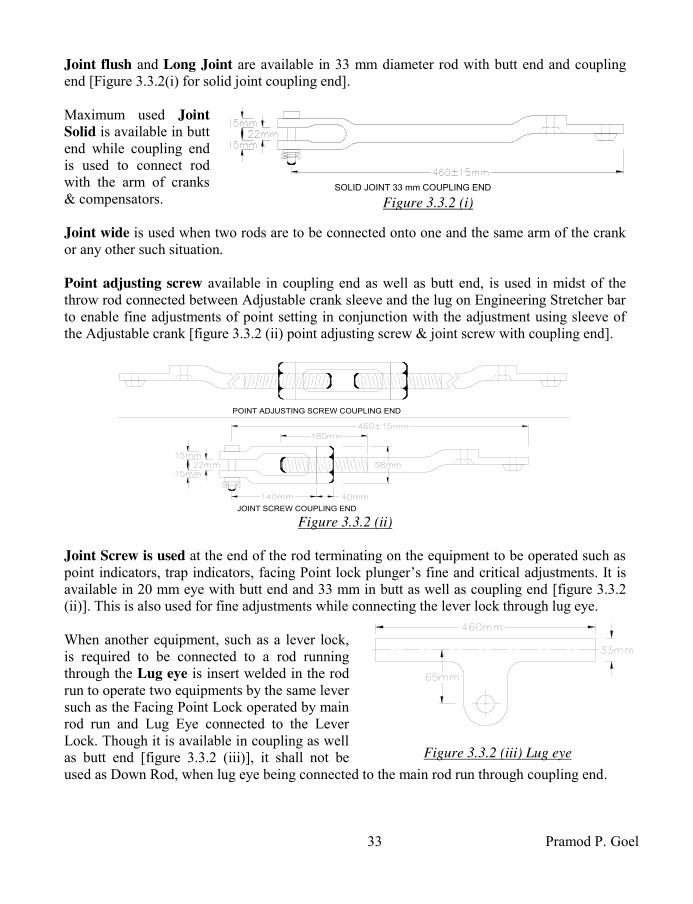
33 Pramod P. Goel
Joint flush and Long Joint are available in 33 mm diameter rod with butt end and coupling end [Figure 3.3.2(i) for solid joint coupling end].
Maximum used Joint
Solid is available in butt end while coupling end
is used to connect rod with the arm of cranks & compensators.
Joint wide is used when two rods are to be connected onto one and the same arm of the crank or any other such situation.
Point adjusting screw available in coupling end as well as butt end, is used in midst of the throw rod connected between Adjustable crank sleeve and the lug on Engineering Stretcher bar to enable fine adjustments of point setting in conjunction with the adjustment using sleeve of the Adjustable crank [figure 3.3.2 (ii) point adjusting screw & joint screw with coupling end].
JOINT SCREW COUPLING END
POINT ADJUSTING SCREW COUPLING END
Figure 3.3.2 (ii)
Joint Screw is used at the end of the rod terminating on the equipment to be operated such as point indicators, trap indicators, facing Point lock plunger’s fine and critical adjustments. It is available in 20 mm eye with butt end and 33 mm in butt as well as coupling end [figure 3.3.2 (ii)]. This is also used for fine adjustments while connecting the lever lock through lug eye. When another equipment, such as a lever lock, is required to be connected to a rod running through the Lug eye is insert welded in the rod run to operate two equipments by the same lever such as the Facing Point Lock operated by main rod run and Lug Eye connected to the Lever Lock. Though it is available in coupling as well as butt end [figure 3.3.2 (iii)], it shall not be used as Down Rod, when lug eye being connected to the main rod run through coupling end.
SOLID JOINT 33 mm COUPLING END Figure 3.3.2 (i)
Figure 3.3.2 (iii) Lug eye

Indian Railway Signal Engineering Volume-III
34
Connection of the rod to the switch rail is done through Swan Neck or Goose Neck. The Swan Neck shall be used while connecting to the far end Switch rail and Goose Neck while being connected to the near end Switch rail respectively.
Point rod coupling: Coupling end joints of the adjoining rod, couple with each other are designed such that these hold each other firmly while the role of nuts and bolts is limited to keep the joints held together in position, without applying any shearing force on these bolts [figure 3.3.2 (iv)]. 3.3.4 Trestle & Standard Roller Guide: The Rod rests on the bottom roller of the Standard Roller Guide. Top Roller is held in position through a pin driven across the Top Roller’s axis, fastened with the Standard Roller Guide, placed over the rod, using split pins. The Standard Roller Guide is designed to have space to allow rolling of the top roller pin and the bottom roller to cover 8" travel of the rod. The entire assembly shall be erected and maintained to have minimum friction to the rod. 3.3.4.1 Trestle: Trestle, the cast iron base of 380 mm (15") height embedded into ground and rammed properly so as not to allow lateral or sideways tilting, are spaced by 2.2 metres (7') for solid rod and 1.85 metres (6') for tubular rod. 1.85 metres space is maintained in case of curvature in the rod run for solid as well as tubular rods. Two trestles one over the other shall be fastened with each other using bolts and nuts where ground earth is not consolidated enough to withstand forces when the rod is moved by lever or back thrust during movement of train over the trailing points [Figure 3.3.4.2]. Each trestle shall be absolute horizontal as well as absolute vertical and finally also the rod run which shall be checked using spirit level for being perfect horizontal. Undulated rod run shall cause heavy friction while rod level inclined to horizontal shall add to extra effort to work against the weight component of the rod depending upon angle of inclination. Cast iron Trestles are designed to be two-way and four-way. 3.3.4.2 Standard Roller Guide: [Figure 3.3.4.2] Cast iron Standard Roller Guide is fixed onto the trestle top with bolts and nuts with head below and tightened. Head of the bolt is kept below to enable catching attention during inspection of unscrewed bolt and timely tightening.
Figure 3.3.2 (iv) Point rod coupling
TOP ROLLER
SPLIT PIN
RODBOTTOM
ROLLER
96m
m66m
m380m
m
STANDARD
ROLLER
GUIDE
TRESTLE
Figure 3.3.4.2
Trestle and Standard Roller Guide

35 Pramod P. Goel
Bottom roller’s in-built extended axle rests loose on seat of the pair of Standard Roller Guides fastened with the Trestle. The pin bearing the Top Roller is fastened with the pair of Standard Roller Guides after the rod is laid on the bottom roller. It may be noted that for the purpose of taking the rod out of the set of Standard Roller Guides shall be obstructed by the Coupling End of the rod once the top rollers have been fastened. Keeping this in view the joints shall be kept away from any of the Trestle as well as the coupling joint shall be freed of nuts and bolts before taking the rod out of its seat.
3.3.5 Change of Direction of the Rod run: Right angle straight and equal arm crank is used for change in direction of the rod run which shall be at right angle only. Right angle arm crank may be used for i) furthering the direction of transmission onwards and for ii) reversing of direction of transmission on wards. As the rod running from outside lead-out is connected to one arm of the right angle crank for taking a diversion, the rod to the other arm of the crank shall be pushed for a pushing stroke from the lead-out and vice versa [Figure 3.3.5(i)]. However when the crank is placed reversed thereby reversing the direction of push from the outside lead-out to pull and vice versa, such arrangement shall also compensate the expansion and contraction with ambient temperature variations. This compensation shall be equivalent to larger of the incoming or outgoing length of rods.
Straight arm crank with arms at 1800 to each other, are used to offset the route of rod run by 24 inches poised to run further parallel to the incident route. In this case as the incident stroke is reversed to pushing stroke, this also results in compensating the expansion and contraction of the rod with variation in ambient temperature. Relief Crank is used for diverting the route within 200 angle [Figure 3.3.5]. The one arm crank base is fixed on the Cast Iron foundation and when the number of rods is more, on the MS plate fixed on cast iron foundations grouted into ground with sand, cement & gravel aggregate. The crank arm is extended to hold the rod through solid joints one from the out side lead out end and other towards equipment end. 3.3.6 Rod passing under track and level crossing gate: As and when the rod run is required to pass under the track, the rod shall continue to be supported on the trestles and standard roller guides such that i) no trestle shall fall below the rails even at the cost of reduction of inter Trestle distance, ii) only one pair of rods shall pass through across the track
Figure 3.3.5 Relief crank

Indian Railway Signal Engineering Volume-III
36
distributing other than two rods crossing through further spans between the sleepers under the track which shall never be consecutive. As and when the rod run is required to pass through level crossing road, a channel shall be cut across the level crossing road suitable enough to accommodate, all Trestles placed side by side such as to bear all rods required to cross the road. The channels may be constructed strong enough to be able to withstand the road traffic load, plastered with sand cement and covered by MS sheets counter sunk to accommodate flat headed bolts. The other arrangement is providing two channel irons running parallel to each other, placed in the trench so cut to accommodate all the trestles placed side by side, provided with spacer steel tubes in regular interval tightened both the channel irons by bolts and nuts passing through these tubes. The channels shall be covered by Mild Steel sheets and fastened with the flange of the channel using nuts and bots.
3.3.7 Rod compensation: It is the linear elongation and contraction of the Rod in proportion to the variations in ambient temperature calculable based on coefficient of linear expansion for forge iron being 11.3 x 10⁻⁶ metre, per Centigrade or 0.24 inches per 100 yards per 100 F rise of temperature. Accordingly longer the rod run more is the expansion and contraction with increase or decrease of ambient temperature. 200 mm stroke at the lever Tail if reaches, under ideal conditions, at the Adjustable crank connected to the point, is adjusted by the sleeve on the other arm of the crank to impart throw of 125 mm (4½") at the ‘Toe’ of the point. Points are religiously tested with 5 mm obstruction piece placed at 150 mm from the Toe of the switch, in between stock rail and tongue rail and attempting to plunge the facing Point Lock plunger which should not be able to be plunged-in at the same time it should not be possible for the signal slide to move across the point slides. This test is conducted to ensure that the wheel flange is not able to make its way through between tongue rail and the stock rail, resulting in no-road condition and derailment. However a sharp wheel flange may still be able to pierce through between Tongue Rail and Stock Rail derailing the train. Rod Compensators are used to eliminate the conditions of creating gap between the Stock Rail and the Tongue Rail affected by variation in ambient temperature.
Figure 3.3.7(i) Rod Compensator

37 Pramod P. Goel
3.3.7.1 Rod Compensator: It is an assembly of i) cast iron base with four holes and two stud pins, ii) one acute angle crank, ii) one obtuse angle crank and iii) one link to connect the acute angle crank with the one arm of obtuse angle crank. The Rod Compensator base is mounted on the Cast Iron Foundation is fixed using nuts and bolts. The foundation is embedded into ground and concreted with sand, cement & gravel aggregate. The base bearing two Stud Pins, distanced with each other by 545 mm centre to centre, to hold one obtuse angle crank of 1200 and one acute angle crank of 600 connected with each other through a Link. The arm of each crank to which rod is connected shall be 406 mm (16"). The complete assembly is termed as Rod Compensator [Figure 3.3.7(i)]. It may be seen that a pull on one arm of the rod compensator gets translated to push on the other arm thereby absorbing the expansion/contraction of the rod keeping the fixed points viz. lever and the arm of the adjustable crank unaffected by variation in ambient temperature. Such points are termed as neutral points. The other unsolicited affect of the compensator is to reverse the direction of movement of the rod imparted by the lever gets reversed at the equipment side of the compensator while maintaining the lever and the equipment un-effected. The acute angle crank arm shall be connected to the rod coming from the Lever Tail side. It is pertinent to note that the compensator shall function normal within the limiting stroke, beyond which disproportionate variations in the stroke shall take place. The compensator is placed to join the rod aligned normal to the rod run keeping straight with compensator arms placed in or out corresponding to the lever being normal or reversed. Movement of 406 mm arms of the compensator, about the stud pins, is radial resulting in flexing of rod with reference to rod alignment which is maximum when both the arms of the compensator are right angles to the rod alignment. This flexing of rod is away from the line running centre to the rod run alignment. As such, i) undesirable increase of distance of the trestle/standard roller guide nearest to the crank of the compensator shall have to be done to avoid rubbing and jamming of the rod with the Standard Roller Guide. ii) Due to increase flexing the stroke on the rod which shall be one-is-to-one shall become out of proportion. To avoid the undesirable increase of distance of the trestle/standard roller guide nearest to the crank of the compensator, the maximum flexing of the rod to its alignment shall be limited to 15 mm (0.6"). As acute angle crank arm is imparted a stroke extra beyond the normal stroke by 25 mm (1") the other obtuse angle arm shall deflect by 37 mm (1.5") if the acute angle crank arm is imparted another stroke of 25 mm (1") in the same direction the obtuse angle crank arm shall deflect further by 68 mm (2.75"). This erratic behaviour shall create a dangerous condition, if the rod run is meant to operate point causing gap in the point with lever being in normal or reverse position. Accordingly the maximum radial movement of the compensator arms, keeping safety margin, is restricted to 22-1/20 to either side of arm’s mean position.
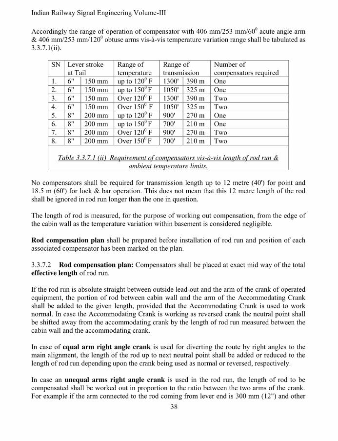
Indian Railway Signal Engineering Volume-III
38
Accordingly the range of operation of compensator with 406 mm/253 mm/600 acute angle arm & 406 mm/253 mm/1200 obtuse arms vis-à-vis temperature variation range shall be tabulated as 3.3.7.1(ii).
SN Lever stroke at Tail
Range of temperature
Range of transmission
Number of compensators required
1. 6" 150 mm up to 1200 F 1300' 390 m One
2. 6" 150 mm up to 1500 F 1050' 325 m One
3. 6" 150 mm Over 1200 F 1300' 390 m Two
4. 6" 150 mm Over 1500 F 1050' 325 m Two
5. 8" 200 mm up to 1200 F 900' 270 m One
6. 8" 200 mm up to 1500 F 700' 210 m One
7. 8" 200 mm Over 1200 F 900' 270 m Two 8. 8" 200 mm Over 1500 F 700' 210 m Two
Table 3.3.7.1 (ii) Requirement of compensators vis-à-vis length of rod run &
ambient temperature limits.
No compensators shall be required for transmission length up to 12 metre (40') for point and 18.5 m (60') for lock & bar operation. This does not mean that this 12 metre length of the rod shall be ignored in rod run longer than the one in question. The length of rod is measured, for the purpose of working out compensation, from the edge of the cabin wall as the temperature variation within basement is considered negligible. Rod compensation plan shall be prepared before installation of rod run and position of each associated compensator has been marked on the plan. 3.3.7.2 Rod compensation plan: Compensators shall be placed at exact mid way of the total effective length of rod run. If the rod run is absolute straight between outside lead-out and the arm of the crank of operated equipment, the portion of rod between cabin wall and the arm of the Accommodating Crank shall be added to the given length, provided that the Accommodating Crank is used to work normal. In case the Accommodating Crank is working as reversed crank the neutral point shall be shifted away from the accommodating crank by the length of rod run measured between the cabin wall and the accommodating crank. In case of equal arm right angle crank is used for diverting the route by right angles to the main alignment, the length of the rod up to next neutral point shall be added or reduced to the length of rod run depending upon the crank being used as normal or reversed, respectively. In case an unequal arms right angle crank is used in the rod run, the length of rod to be compensated shall be worked out in proportion to the ratio between the two arms of the crank. For example if the arm connected to the rod coming from lever end is 300 mm (12") and other

39 Pramod P. Goel
arm is 150 mm (6"), the ratio of transformation shall be 1: ½ i.e. the 200 mm (8") stroke transmitted at the 200 mm (12") arm of the crank shall be reduced to 100 mm (4") stroke. Accordingly the length of the rod connected to the 150 mm (6") arm shall be doubled as reflected upon original straight rod run for the sake of calculation of effective length of the rod and added or subtracted according to the uneven arm crank being used as normal or reverse, respectively. Similar shall be condition with Right Angle or Straight arm Adjustable crank. As the stroke at the lug of Engineering Stretcher bar is required to be 4½" for setting of points the sleeve of the crank shall be adjusted at 6.75" from the stud pin of the crank. Although in practice the 200 mm (8") stroke at the lever tail reaches reduced at the point because of the wear, tear & play in cranks and compensators the same may reach around 6" (150 mm) at the 300 mm (12") arm of the adjustable crank. In such a situation the sleeve shall be required to be at 9" from the stud pin of the Adjustable Crank to obtain 115 mm (4½") throw on the throw rod. Rod compensation plan shall be prepared based on the principles discussed, for each layout depending upon prevailing conditions. i) Rod Compensation plan Condition (i): [Figure 3.3.7.2(i)] Consider straight part of the 400' rod running out of cabin wall terminates at 300 mm (12") arm of the unequal arm
right angle crank which in turn is connected normal and a 50' rod is connected to the other 150 mm (6") arm. Since the 50' rod is connected to the other arm of the unequal arm crank connected normal the equivalent effective length of the rod should have been 50' but for the arm ratio of the crank being 2:1, it shall be 100'. As such the effective length of the entire rod run shall work out to be 400' + 100' = 500'. Accordingly the Compensator shall be placed at 250' from the cabin wall which is midpoint of the effective length 500'. ii) Rod Compensation plan Condition (ii): [Figure 3.3.7.2(ii)] Consider straight part of the 400' rod running out of cabin wall straight, terminates at 300 mm (12") arm of the equal
arm right angle crank connected reversed and a 100' rod is connected to the other 300 mm (12") arm.
50'
100'400'250'250'
6"
12"
CA
BIN
WA
LL
Figure 3.3.7.2(i) Rod compensation plan condition(i)
100'
100'300'150'150'
CA
BIN
WA
LL
Figure 3.3.7.2(ii) Rod compensation plan
condition(ii)

Indian Railway Signal Engineering Volume-III
40
Since the equal arm crank is connected reversed the 100' rod connected to the other arm of equal arm right angle crank, the same 100' rod shall reflect back to neutralise this part of the rod having been compensated, the effective length of the rod run shall be 400' (-) 100' = 300'. Accordingly the compensator shall be placed at a distance of 150' from the wall of the cabin. iii) Rod Compensation plan Condition (iii): [Figure 3.3.7.2(iii)] Consider the rod run operating one crossover. Accordingly the rod shall be grouped in two parts; first part shall have neutral point at the cabin wall and second neutral point shall be at the arm of first Adjustable Crank for operation of first point. The neutral point of other part of the rod shall be at the arm of the first Adjustable Crank to operate first point of the crossover and on the arm of other Adjustable Crank to operate second point of the crossover. Two compensators ‘C-1’ & ‘C-2’ shall be provided because of having four neutral points in the rod run, two at the cabin and the arm of the first adjustable crank and two at the arm of the first adjustable crank and at the arm of second adjustable crank. Consider total straight rod including both groups being 850' out of which first group being 550' and second being 300'; first throw rod being 30' and second being 14'. Rod running out beyond cabin wall joining at one arm of the Accommodating Crank at the outside lead-out, the rod connected at the other arm of the Accommodating Crank gets terminated at the arm of the rod compensator C-1. The rod runs further one end connected to the other arm of the compensator and other end at the 300 mm (12") arm of the Adjustable Crank placed reversed to the incident rod run, for operating the near end point of the crossover. Another set of rod run connected to the 300 mm (12") arm of the Adjustable Crank using Wide Joint, at the near end point of the crossover and to the 300 mm (12") arm of the Adjustable Crank to operate far end point of the same crossover. It may further be considered that the sleeves of both the adjustable cranks are adjusted at 178 mm (7"). It may be observed that the Adjustable Crank to operate near end point of the crossover is connected reversed so far as the rod run between cabin wall and the near end point is concerned, the same crank is connected normal with reference to the rod run between near end point and far end point of the crossover. However the second Adjustable Crank to operate far end point of the crossover is connected reversed so far as the rod run between both points are considered. Accordingly the total effective length of the rod to provide the Compensator C-1, between cabin and the arm of the Adjustable crank for operating the near end point of the crossover works out to be 14'+550'- 51.4' = 512.6'. Accordingly the central line of the Compensator C-1 shall be positioned at a distance of 242.3' measured from the stud pin of the Accommodating Crank arm at the out side lead out kept right angles and the central line of the compensator. The remaining distance between the central line of the compensator C-1 and the stud pin of the first Adjustable Crank meant for operation of the near end point of the crossover shall workout to be 307.7'.
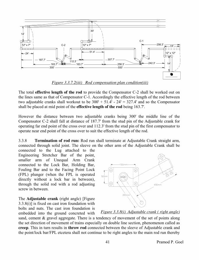
41 Pramod P. Goel
The total effective length of the rod to provide the Compensator C-2 shall be worked out on the lines same as that of Compensator C-1. Accordingly the effective length of the rod between two adjustable cranks shall workout to be 300' + 51.4' - 24' = 327.4' and so the Compensator shall be placed at mid point of the effective length of the rod being 163.7'. However the distance between two adjustable cranks being 300' the middle line of the Compensator C-2 shall fall at distance of 187.7' from the stud pin of the Adjustable crank for operating far end point of the cross over and 112.3' from the stud pin of the first compensator to operate near end point of the cross over to suit the effective length of the rod.
3.3.8 Termination of rod run: Rod run shall terminate at Adjustable Crank straight arm, connected through solid joint. The sleeve on the other arm of the Adjustable Crank shall be connected to the Lug attached to the Engineering Stretcher Bar of the point, smaller arm of Unequal Arm Crank connected to the Lock Bar, Holding Bar, Fouling Bar and to the Facing Point Lock (FPL) plunger (when the FPL is operated directly without a lock bar in between), through the solid rod with a rod adjusting screw in between. The Adjustable crank (right angle) [Figure 3.3.8(i)] is fixed on cast iron foundation with bolts and nuts. The cast iron foundation is embedded into the ground concreted with sand, cement & gravel aggregate. There is a tendency of movement of the set of points along the set direction of movement of trains especially on double line section, phenomenon called as creep. This in turn results in throw rod connected between the sleeve of Adjustable crank and the point/lock bar/FPL etcetera shall not continue to be right angles to the main rod run thereby
14'
51.4'
550'
256.3'
12" x 12"
12" x 7" 14'12" x 7"
24'
256.3'163.7' 163.7'
300'
C-2
C-1
14'
30'
242.3'
307.7'112.3'
187.7'
Figure 3.3.7.2(iii) Rod compensation plan condition(iii)
Figure 3.3.8(i) Adjustable crank ( right angle)
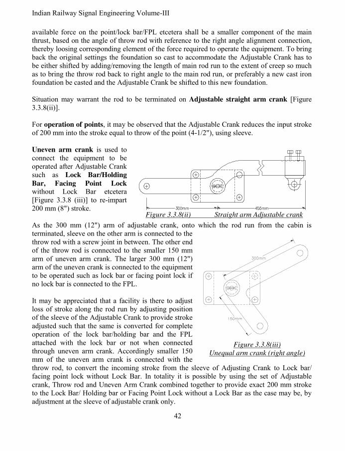
Indian Railway Signal Engineering Volume-III
42
available force on the point/lock bar/FPL etcetera shall be a smaller component of the main thrust, based on the angle of throw rod with reference to the right angle alignment connection, thereby loosing corresponding element of the force required to operate the equipment. To bring back the original settings the foundation so cast to accommodate the Adjustable Crank has to be either shifted by adding/removing the length of main rod run to the extent of creep so much as to bring the throw rod back to right angle to the main rod run, or preferably a new cast iron foundation be casted and the Adjustable Crank be shifted to this new foundation. Situation may warrant the rod to be terminated on Adjustable straight arm crank [Figure 3.3.8(ii)]. For operation of points, it may be observed that the Adjustable Crank reduces the input stroke of 200 mm into the stroke equal to throw of the point (4-1/2"), using sleeve. Uneven arm crank is used to connect the equipment to be operated after Adjustable Crank such as Lock Bar/Holding
Bar, Facing Point Lock without Lock Bar etcetera [Figure 3.3.8 (iii)] to re-impart 200 mm (8") stroke. As the 300 mm (12") arm of adjustable crank, onto which the rod run from the cabin is terminated, sleeve on the other arm is connected to the throw rod with a screw joint in between. The other end of the throw rod is connected to the smaller 150 mm arm of uneven arm crank. The larger 300 mm (12") arm of the uneven crank is connected to the equipment to be operated such as lock bar or facing point lock if no lock bar is connected to the FPL. It may be appreciated that a facility is there to adjust loss of stroke along the rod run by adjusting position of the sleeve of the Adjustable Crank to provide stroke adjusted such that the same is converted for complete operation of the lock bar/holding bar and the FPL attached with the lock bar or not when connected through uneven arm crank. Accordingly smaller 150 mm of the uneven arm crank is connected with the throw rod, to convert the incoming stroke from the sleeve of Adjusting Crank to Lock bar/ facing point lock without Lock Bar. In totality it is possible by using the set of Adjustable crank, Throw rod and Uneven Arm Crank combined together to provide exact 200 mm stroke to the Lock Bar/ Holding bar or Facing Point Lock without a Lock Bar as the case may be, by adjustment at the sleeve of adjustable crank only.
Figure 3.3.8(ii) Straight arm Adjustable crank
Figure 3.3.8(iii)
Unequal arm crank (right angle)

43 Pramod P. Goel
3.3.9 Process of smith welding at site: Many a times, especially while carrying out maintenance activity the rod may be required to be cut short, elongated by adding a piece, joined to the solid joint or Adjusting screw with butt end or for any other reason has to be done by the black smith, at site. The ends of the rod shall be heated to red hot short of conditions of flowing of the metal using a portable hand operated blower and burning hard coal. The ends of both the rods are tapered, elongated and hammered to join both ends, giving a fine finish without any cracks between the two.
3.3.10 Maximum permissible limits for point operation: Maximum permissible limits for point operation by the lever under single wire system and the Double wire lever used on the lever frame under single wire system:
3.3.10.1 Rod worked points from single wire lever frame operated by single wire lever: Rod worked points operated by lever from cabin may be operated up to the distance: i) Single ended points, with 150 mm (6") stroke at lever tail, within 320 metres (350
yards). ii) Single ended points, with 200 mm (8") stroke at lever tail, within 460 metres (500
yards). iii) Double ended points on running lines with 150 mm (6") stroke, within 180 metres
(195 yards). iv) Double ended points on running lines with 200 mm (8") stroke can be operated up to
275 metres (300 yards). 3.3.10.2 Rod worked points from single wire lever frame operated by Double wire lever: Rod operated points with double wire lever using 500 mm (20") stroke drum may be operated up to the distance: i) 500 metres (550 yards) for points and locks. ii) 1200 metres (1300 yards) for signals without detectors. iii) 600 metres (650 yards) for a single or coupled detector lever transmission. iv) Rod worked single ended points operated by levers with 150 mm (6") stroke, within
320 metres (350 yards) from the cabin.
*****

Indian Railway Signal Engineering Volume-III
44
CHAPTER- IV
SIGNALS
4.0 Signals: Semaphore signals shall be lower quadrant or upper quadrant. Lower quadrant signals are operated by Single wire. Such signals are mounted on lattice or tubular post. Two type of spectacles used are, type ‘A’ and type ‘B’. Signal lamp is used for illuminating the signals during night. The Signal lamp consists of a clear stepped lens at the focal point of which the lamp wick/filament is placed so as to emit a parallel beam of light to enable the Loco Pilot see the signal aspect from a reasonable distance. The clear light as emitted by the lamp is passed through red, yellow or green roundel as fixed onto the spectacle and positioned opposite the Signal Lamp, for the loco Pilot to see the signal aspect. Arm is fastened to the spectacle with bolts and nuts, which shall be square ended or fish tail ended. The arm is enamel painted and is coloured red or yellow with white strip band to enable the Loco Pilot know the type of signal which shall be either running Stop signal or the Warner or Distant signal. As the wire from the Lever Tail running through inside lead-out, out side lead-out, pulleys fixed on pulley stakes, signal slide of the point detector and horizontal wheel fixed onto the signal post, is connected to the Counter Weight Lever, the down rod connected between the Counter Weight Lever and the spectacle is pushed up, to take the signal Off. Provision of Spread light lens is made by providing spherical outer surface on a part of outer stepped lens to spread a part of the focussed beam on horizontal plane to be visible to the loco pilot while travelling on a curve approaching the signal. Subsidiary signals such as Dwarf signal, Calling-on signal, Shunt signal, Point Indicators & trap indicators are also used for controlling and shunting movements of the trains within the Station Section. 4.1 Signal fittings: While signal constitutes of large number of parts, for the Loco Pilot it is spectacle with an arm. The spectacle is mounted on the signal post which may be tubular or lattice, besides many more type of posts, not in use any more. The fittings for the signal are for type ‘A’ Spectacle and type ‘B’ Spectacle. Main parts of the signal are, i) Signal Post, its base, Pinnacle, Ladder & Ladder foundation, ii) Signal dolls 3.6 metres and 2.6 metres, iii) Hook bolt, iv) Purlin, v) Angle stay, vi) Hand rail with deck, vii) Stay, viii) Girder, ix) Channel Post, x) Flange ‘A’ and Flange ‘B’, xi) Semaphore spectacle, xii) Semaphore bracket, xiii) Semaphore Bearing, xiv) Back light screen, xv) Signal Arm, xvi) Stop, xvii) Shock absorber ‘A’ & ‘B’, xviii) Lamp bracket, Lamp bracket carrier and Lamp bracket support, xix) Signal Lamp, xx) Counter weight lever 1 way, 2 way, 3 way and Counter weight support, xxi) Eye joint 20 mm & MS bar 20 mm, xxii) Screw joint 20 mm, xxiii) Wheel clamp, ‘U’ bolt 140 mm diameter tube, horizontal rope wheel 1 way, horizontal rope wheel 2 way, horizontal rope wheel 3 way ‘A’ & ‘B’, xxiv) Rod guide, xxv) Wire shackle, xxviii) Roundels convex, red & green type ‘A’ & ‘B’, xxvi) Clamp 140 mm diameter tube, xxvii) Anchor bolts, xxviii) ‘U’ bolts, xxix) Nuts, Bolts, Washers, Spring washers & Screws.

45 Pramod P. Goel
4.1.1 Signal post Tubular: Tubular signal post is erected on a Cast Iron (CI) base mounted on foundation with its top at rail level or is buried under ground. The post is in two parts upper portion invariably being 5.96 metres (18') in length with outer diameter of 140 mm (5.5"). The post for the lower portion shall cover the balance of the total length of the signal post, with outer diameter being 168 mm (6-5/8"). Thickness of the sheet for both pipes shall be 7.9 mm (5/16"). Both tubes are joined together by inserting the smaller diameter post into the larger diameter post with 460 mm (18") overlap. The lower part which has diameter larger than the other one is pressed hard against the tube of upper part of the post, by swaging process, using swaging tool compressed to the extent to hold the upper tube rigidly in process. Typical over all length of the tubular signal posts is tabulated as 4.1.1. The signal post is inserted onto Cast Iron Signal
Base of a circular table of 512 mm (1'8½") diameter and 41 mm (1-5/8") thickness, with four oblong holes to accommodate the 25 mm (1") diameter foundation anchor bolts, which in turn are fastened with nuts to the bolts of the foundation, casted with sand, cement and gravel aggregate. The circular table and a concentric pipe perpendicular to the base, form a monolithic Cast Iron Base of 550 mm (1'10") height. The pipe of the base is cast tapering gradually downwards from the orifice to allow convenient housing of the 168 mm diameter signal post such that the signal post when inserted into the base, the pipe gets stuck-up at about 50 mm (2") above the bottom of the base. The signal post is plumbed vertical, filled with angular iron wedges between the outer surface of the signal post and inner surface of the pipe of the signal base to hold the post in position rigidly, rest of the space is filled with old rope or some similar material to fill in the empty space. The bitumen is filled to seal the balance space up to a level 50 mm (2") above the orifice of the pipe of the signal base. The Cast Iron signal base may also embedded into ground. 4.1.2 Signal post Lattice: Lattice signal post is available in riveted and welded versions. Four angle irons placed to frame rectangular shape, rising from larger base to narrowing down upwards are kept held rigidly together by iron strips riveted or welded to the angle irons. The tapering is at the rate of 1/8" per foot varying according to the length of the post ending as 175 mm (7"), square as the top of the post. Standard lengths of the post are 6.7 metres, 7.2 metres, 8.2 metres, 9.2 metres, 10.2 metres, 11.2 metres, 12.1 metres & 13.6 metres. The post is held fixed with the anchor bolts casted to the sand, cement and gravel aggregate foundation top of which is kept at rail level, or may be buried in the ground. Batten plates are riveted to the post at an appropriate high position, meant to bear the signal fittings.
SN Post fixed on base at rail level
Post buried under ground
1. 6.7 m (22') 8.2 m (27') 2. 7.2 m (24') 9.2 m (30') 3. 8.2 m (27') 10.2 m (33') 4. 9.2 m (30') 11.2 m (36') 5. 10.2 m (33') 12.2 m (39')
6. 11.2 m (36') 13.2 m (42')
Table 4.1.1 Standard overall lengths of
tubular signal post on base and buried

Indian Railway Signal Engineering Volume-III
46
4.1.3 Bracket Signal Main Posts: While more than one signal such as Outer & Warner can be mounted onto one signal post, two or more signals for more than one diverging or converging routes of the station yard shall be mounted on Dolls the miniature tubular signal posts. Such signal posts shall be i) channel iron post, ii) tubular post or iii) Lattice post. 4.1.3.1 Bracket Signal Posts: Bracket Signal Posts also termed as Dolls, the miniaturised tubular posts of different lengths of outer diameter 140 mm (5.5") and metal thickness being 6 mm, are fixed onto the cross Boom or Gantry to bear the ‘A’ or ‘B’ type signal assembly. Signals for different routes are placed in sequential order corresponding to the route concerned out of which the doll for the signal meant for main line or most important route is kept tallest. Accordingly tubular Dolls are available in 4.9 metres (17.5'), 3.9 metres (14.5'), 2.9 metres (11.5') and 1.9 (8.5') metres lengths. 4.1.3.2 Channel iron Bracket Main Signal Post: Channel iron Bracket Main Signal Post is made by joining two channel irons each of section 8" x 3" x 15 lbs placed opposite each other mounted on to the 21" x 15" x ½" base plate through angle irons and mild steel plates riveted to the channel iron and the base plate. The assembly is reinforced by riveting mild steel plates with the channel irons up to height of 500 mm from the base. Arrangement for Lattice Bracket Main Signal Post is similar to the Channel iron Bracket Main Signal Post.
4.1.3.3 Tubular Bracket Main Signal Post: The tubular Bracket Main Signal Post is in two parts the lower part ‘A’ is of lengths 14.5' or 20' with outside diameter as 10.75", metal thickness being 3/8". The upper part ‘B’ is of 7.5' length with metal thickness of 3/8". Accordingly overall signal post length is kept as 22' and 27.5'. The process of joining two parts shall be same as described in the main signal posts. 4.1.3.4 Boom: Boom, the assembly to bear two or three dolls, the miniature signal posts, is prepared and cross supported using mild steel plates and angle irons riveted to Bracket Main Signal Channel Iron Post. Vertical dimension of the Boom is of 290 mm (11.5") and is fixed rigidly to the Bracket Main Signal Channel Iron Post maintaining minimum space of 5450 mm (17' 10.5") between the bottom of the base plate and lowest portion of the boom, placed onto the channel iron post such that the cross point centre of the boom and the central line along the length of the post coincide with each other, to make the assembly self balanced and stable. A wooden deck board is fitted on the top of the Boom. In case of a two doll arrangement two flanges one above the other are fixed on the boom framework at the centre being 975 mm (3.25") from the centre line of the post on either side onto the boom. The flange ‘A’ is of uniform diameter 143 mm (5-5/8") and flange ‘B’ is of tapered from top as 143 mm (5-5/8") to bottom of the flange as 140 mm (5-3/8") with the result that while the doll post of diameter 143 mm (5-5/8") passes through the flange ‘A’ to flange ‘B’ it is stuck-up at the point above the bottom of flange ‘B’, thus held rigidly fixed in position between two flanges. The post of the doll is tightened in position by bolts provided on the periphery of the flange [Figure 4.1.3.5].

47 Pramod P. Goel
Arrangement for second doll is same as discussed above. The boom is provided with a guard railing to protect workmen from getting out of balance and falling down.
Similar arrangement shall be made to erect and fix Boom onto the Lattice and Tubular
Bracket Signal main Posts. 4.1.3.5 Signal Gantry: When the number of dolls exceeds four, Dolls are fixed onto a signal bridge/ Gantry supported on square based parallel lattice posts, fixed on sand, cement and gravel aggregate foundation through anchor bolts and nuts holding the base plate of the post, at an appropriate height keeping in view Schedule of Dimensions1, ensuring the signals being placed over the corresponding track for clear identification, keeping the doll for the signal meant for main line or most important route as tallest [figure 4.1.3.5].
4.1.4 Pinnacle: Pinnacle is the cap put and fastened on the top of the post to demark its top, prevent unwanted material & rain water to pour into the tube of the post, to cover outer periphery of the tube or lattice post. 4.1.5 Ladder & Ladder
foundation: A ladder made of pair of mild steel flat connected to steps, is erected and clamped with the signal post at 225 mm (9") below the top of the post, supported by stays connected with collars clamped onto the post at suitable intervals so as to ensure that the ladder does not flex under the weight of the person climbing or working on the ladder. A guard rail is provided 1200 mm (4') below the fulcrum of he signal spectacle be it type ‘A’ or ‘B’ to enable the person work conveniently and safely. The end of the ladder is fastened with the cast iron Ladder Foundation, which is firmly embedded into ground.
_______________________________________________________________________ 1Refer Indian Railway Signal Engineering Volume-I, for schedule of dimensions.
RAIL LEVEL
1980 mm
1980 mm
915 mm
FLANGE 'A'
FLANGE 'B'
COUNTER WEIGHT 2500 mm
5450 mm
ROPE WHEEL
CHANNEL 8" X 3" X 15.96 Lbs.
DOWN ROD
Figure 4.1.3.5 Signal Gantry

Indian Railway Signal Engineering Volume-III
48
4.1.6 Semaphore signal fittings: The lower quadrant system of Signalling is two aspect, accordingly the signal assembly mounted on the signal post has two roundels in the Spectacles which are of type ‘A’ and type ‘B’. Accordingly the entire fittings are designed to suit either type of spectacle. The set of fittings are correspondingly termed as fittings type ‘A’ and fittings type ‘B’ respectively. Main parts of the assembly are i) Semaphore Spectacle, ii) Roundels convex, iii) Semaphore Bracket/Bearing, iv) Signal Arm, v) Counter Wight Lever, vi) Stop, vii) Down Rod, viii) Signal Lamp & Lamp bracket and ix) Back Light Screen. 4.1.6.1 Semaphore fittings type ‘A’: As already discussed in preceding paragraph, the Semaphore fittings are almost similar with design different to each other [Figure 4.1.6.1]. i) Semaphore Spectacle: Cast iron
Semaphore Spectacle has circular space to accommodate 213 mm (8-3/8") diameter red and 245 mm (9-5/8") diameter green Roundels fastened with the Spectacle through Roundel Rings fixed on front side of the Spectacle, with screws; respective diameters in the spectacle being 200 mm (7-7/8") & 232 mm (9-1/8"). The centres of the roundels cast 500 angle and 330 mm radius onto the fulcrum. The hole in the spectacle to accommodate the Stud Pin is circular shaped. The signal arm is fixed onto the spectacle with four bolts. The spectacle is mounted on Semaphore Bracket [figure 4.1.6.1(i)]. Roundels are plain coloured glass of thickness same as that of the lens of the Signal Lamp. ii) Semaphore Bracket: Semaphore Brackets are different for tubular and lattice posts. For tubular post, Semaphore Bracket is in two parts Front Clamp & Back Clamp, each having concave surface inside to accommodate 140 mm (5.5") tubular signal post within. Both parts are fastened with each other having the signal post in between and tightened with bolts and nuts. The Front Clamp has a hole on its convex surface onto which 31 mm (1.24") diameter stud pin is riveted to bear the Spectacle which shall work as fulcrum about which the Spectacle revolves. Adjacent to this Stud Pin a projection in casting is
SCREW
JOINT
20mm
380mm
90mm
SEMAPHORE
SPECTACLE
TYPE `A'
GUIDE
DOWN ROD
SEMAPHORE BRACKET
COMPLETE TYPE `A'
600 mm app.
700 mm app.
SEMAPHORE ARM
2 WAY ROPE
WHEEL
HORIZINTAL
WHITE BAND
ON FRONT
WIRE ROPES
PINACLE
PAINTED RED
SEMAPHORE ARMPAINTED YELLOW
Figure 4.1.6.1 Semaphore fittings
2 signals, type ‘A’ on the same post

49 Pramod P. Goel
extended to work as Stop onto which the Spectacle shall rest when normal, to prevent it from cocking (arm lifting upwards). The Back Clamp has two holes into which signal lamp bracket is to be fixed with bolts. For lattice post a rectangular cast iron Bracket is fitted to the post with two bolts into slotted holes. 31 mm (1.24") diameter stud pin is riveted on to the Bracket to bear the Spectacle. iii) Down Rod: Counter Weight Lever is pulled down as the wire connected to it is pulled by the lever in the cabin. The spectacle is made to rotate about the fulcrum by pull of the Down Rod connected at the back of
Spectacle to 20 mm diameter Stud pin which is screwed into 22 mm (7/8") threaded hole into the Spectacle, using 20 mm eye joint. The other end of the Down Rod is connected through adjustable screw held with a pin, on the Counter Weight Lever. The Stud pin is spaced radial by 154 mm (6"), 250 below the horizontal line running from and across the fulcrum respectively. The linear travel of the down rod is 130 mm (5-1/16"). iii) Counter Weight Lever,
Counter Weight & Counter Weight Bracket: Mild steel Straight Lever i.e. Counter Weight Lever is mounted on to a jaw shaped bracket with holes on both parts of the jaw through which the Straight Lever is pinned in between to swing about the pin and resting on either side of the bracket. The Counterweight is mounted on the Counter Weight Lever on the side same on which the Down Rod is connected. The wire is connected to the other end of the fulcrum on the Counter Weight Lever. It may be noted that the Down Rod is connected at the back of ‘A’ type Spectacle.
The Counter Weight is provided to add to the weight of the Spectacle to ensure complete pulling back of the wire run between the cabin and the Counter Weight Lever when the concerned signal lever is put back to normal. A cast iron Circular Weight is held in position at the Counter Weight Lever by bolts screwed into one of the counter sunk grooves, depending upon the distance between signal and the cabin, due to increase/decrease of the return torque. A bolt is tightened through the hole at the end of the lever to which the counterweight is fixed as a safeguard against slippage of the Counter Weight out of lever. Counter Weights are available in 4 kg, 8 kg, 14 kg and 17 kg unit weights. The Counter Weight Lever may be one way, two way or three way accommodated on one and the same bracket depending upon semaphore signals mounted on one and the same signal post.
200 mm
232 mm
184 m
m
495 mm
50
330 mm R
60 mm
FULCRUM
R 154 mm
STUD PIN HOLE
DIAMETERS FOR ROUNDELS ARE
LARGER THAN AS CUT IN SPECTACLE
0
Figure 4.1.6. (i) Semaphore Spectacle type ‘A’

Indian Railway Signal Engineering Volume-III
50
The Counter Weight Bracket to hold the Counter Weight Lever is clamped with ‘U’ bolts directly with its concave surface butting against the tubular post. It may be noted that the Down Rod is connected opposite the side on which wire is connected
and on the side same on which the counterweight is fixed, with reference to the pivot. The
Counter Weight is mounted on the Counter Weight Lever outside down rod.
The Counter Weight Lever is fixed parallel to the track i.e. right angle to the signal arm. iv) Signal Arm: Signal arm is made of 16 SWG thick mild steel sheet enamel painted Signal Red or Golden Yellow colour, to B.S.S. specifications 381G. The Arm shall be fastened with the spectacle using bolts with packing of Lead washers, Felt washers or wooden blocks in between spectacle and the arm. All holes in the arm shall be 14 mm (9/16") diameter which shall be held in position with 12 mm (0.5") diameter bolts. The ‘A1’ type signal arm is square ended, 1220 mm (4') long and 225 mm (10") outer and 178 mm (7") inner broad ends. The red coloured arm is enamel painted with a 178 mm (7") broad white band at 225 mm (10") from the outer end. The back of the arm is white enamel painted with a 178 mm (7") broad black band spaced by 225 mm (10") from the outer end to be just opposite the white band in front. The ‘A2’ type signal arm is 1220 mm (4') long fish tailed enamel painted red or yellow with white on front band parallel to the fish tail edges of dimensions same as those of ‘A1’ type signal arm. Similarly the back of the arm is enamel painted white with black band parallel to the fish tail edges with similar dimensions as on front.
v) Signal Lamp & Lamp Bracket: During night when the visibility of the signal arm is poor to the extent being not visible, the Red light through red roundels when the Stop signal is On and green light when the signal is Off is illuminated for the Loco Pilot to be guided and action taken by him. For this a signal lamp is hooked onto the ‘L’ shaped Lamp Bracket which is fitted with the Back Clamp of Semaphore Bracket in case of tubular signal post. The upper hole is made oblong while the lower is round so as to enable a 50 margin for vertical alignment of the Lamp Bracket when being fixed onto the Back Clamp. The lamp is fixed on the Lamp Tray such that the flame is placed exactly on the focal point of the stepped lens through which the light emitted by the lamp is a focussed parallel clear light beam while passing through the coloured roundel. In case of lattice signal post the lamp bracket is mounted onto the lamp carrier. The kerosene oil lamp is replaced in different sections by an electric lamp powered by the AC supply of State Electricity Board or generated locally by generators, which can be switched on or off by the Station Master. The electric Signal Lamp is also powered by Direct Current (DC) from a battery bank charged by the Solar Panel with a twilight switch to enable automatic switching On and Off the signal lamp with sunset and sunrise respectively. In either case the

51 Pramod P. Goel
filament of the electric lamp shall be placed at the focal point of the stepped lens of the Signal Lamp. vi) Back Light Screen: The signal lamp is provided with a small orifice covered with glass at the back of the signal lamp to enable the cabin man to see if the Signal Lamp is lit to enable him know that the signal is On, as usually the cabin man is placed at the back of the signal. A screen is fixed with the Spectacle to move with it such that the back light shall not be visible to the Cabin Man when the Spectacle is in between 50 range of being normal. It is important to ascertain that the signal arm has gone back to horizontal/normal when the signal lever is put back to normal or is supposed to be normal when used in conjunction with reverser.
4.1.6.2 Semaphore fittings type ‘B’: The details for ‘B’ type Semaphore fittings shall be read with the details of ‘A’ type fittings as discussed in preceding paragraphs, observing variations in design.
i) Semaphore Spectacle: Cast iron Semaphore Spectacle has circular spaces to accommodate 245 mm (9-5/8") diameter red and green Roundels fastened with the Spectacle through Roundel Rings fixed on back side of the Spectacle, with screws; corresponding diameter of both the spectacles being 9-232 mm (1/8"). The centres of the roundels cast 450 angle and 355 mm (14") radial distance from the fulcrum. The hole in the spectacle to accommodate the spindle is square shaped. The signal arm is fixed onto the spectacle with ¼" x 1½" four bolts. The spectacle is mounted on Semaphore Bearing [Figure 4.1.6.2(i)]. ii) Semaphore Bearing: The Semaphore Bearing is in two parts, the cast iron Bearing Clamp and its counter part Clamp used for tubular post. The cast iron Bearing Clamp holds the spindle and is mounted with its concave part butting against the tubular post, using ‘U’ bolts on its upper part while the lower part is bolted with Counter Clamp. Both parts of the Semaphore Bearing are held together with two bolts. The Lamp Bracket is fitted on the counter part of the Clamp using two bolts. The Spectacle is mounted on the spindle of Semaphore Bearing. The spindle is a mild steel cylindrical rod, its two ends protruding out of the Semaphore Bearing on front and back. Portion on front meant to hold the spectacle and back to hold the back light screen, is square and tapered in shape with end threaded such that the Spectacle is fastened rigidly with the
20
2 m
m 232 mm
232 mm
335 mm
R
130 mm275 mm
DIAMENSIONS FOR ROUNDELS ARE
LARGER THAN AS CUT IN SPECTACLE
450
R 118 mm
28 mm
FULCRUM
HOLE FOR SPINDLE
Figure 4.1.6.2(i) Signal fittings type ‘B’

Indian Railway Signal Engineering Volume-III
52
spindle through square hole of the Spectacle meant for the same and tightened with nut, on threaded part of the spindle. Similarly the Back Light Screen having square hole is fixed on the rear part of the spindle tightened with nut on its threaded part. It is unlike Spectacle type ‘A’ where the Spectacle revolves about the Stud pin where as in case of type ‘B’ fittings it is the spindle which rotates along with the Spectacle and back light screen along with the Spectacle. A rectangular cast iron Semaphore Bracket with an arrangement to bear the spindle with two slotted holes is mounted onto the Lattice
post and fixed using bolts.
iii) Signal Lamp & Lamp Bracket:
While the purpose for providing a signal lamp and associated modifications being same as discussed in case of Type ‘A’ fittings, the arrangement for the Lamp Brackets for type ‘B’ fittings are different which being directly bolted to the plate on the lattice post. iv) Stop: The cast iron Stop used for the spectacle type ‘B’ is spring loaded, an independent unit fixed on an independent bracket with ‘U’ bolts on tubular post. Return of the spectacle back to normal of its weight with a thud may break the roundels, which is avoided due to the spring action. There is provision for adjustment of the spring for the stop so as to match the impact. The stop fitted onto a lattice post is called the shock absorber. The spring loaded stop is fixed onto a cast iron rectangular bracket, which in turn is mounted on the signal post using bolts and nuts through slotted holes onto the bracket. The size of the bracket shall be different and match to the dimension of the post for each signal when two signals are placed on the same post. iv) Down Rod: Counter Weight Lever is pulled down as the wire connected to it is pulled by the lever in the cabin. The spectacle is made to rotate about the fulcrum by pull of Down Rod. A 20 mm diameter Stud pin is screwed into 22 mm (7/8") threaded hole at the line passing through the fulcrum bisecting the centre points of red and green roundels, at distance of 118 mm (4½") from the fulcrum, into the Spectacle. One end of the 120 mm (4') circular mild steel Down Rod is connected at the front of Spectacle to hold the Stud pin with the 20 mm (¾") eye joint. The other end of the Down Rod is connected through adjustable screw held with
LEVELRAIL
SEMAPHORE
SPECTACLE
TYPE `B'
HORIZONTAL
WHEEL 1 WAY
PINNACLE
COUNTER WEIGHT
BRACKET & LEVER 1-WAY
SIGNAL ARM
PAINTED RED
DOWN ROD
WIRE ROPE
WHITE BAND
FOUNDATION
COUNTER
WEIGHT
Figure 4.1.6.2 Signal fittings type ‘B’

53 Pramod P. Goel
a pin, at one of the holes on the Counter Weight Lever usually at a distance of 118 mm (4 ½") from the fulcrum of counter weight lever. The linear travel of the down rod is 99.5 mm (3-13/15"). iii) Counter Weight Lever: Besides the principles and design part of the counter weight lever as discussed in preceding paragraph for type ‘A’ fittings of Counterweight lever the variations for type ‘B’ fittings are discussed here. The Counter Weight Lever may be one way, two way or three way accommodated on one and the same bracket depending upon semaphore signals mounted on one and the same signal post. In case of ‘B’ type fittings, the Counter Weight Bracket has flat surface and is fitted on lattice post using counterweight lever support. Fixing the Counter weight bracket on tubular
post, requires special clamp. The Counter Weight Lever is fixed parallel to the signal arm. iv) Signal Arm: Sheet and paint specifications are same for type “B’ Signal arm as that given under ‘A’ type fittings. However dimensions and other details shall be as detailed below: The ‘B1’ type signal arm is square ended, 1070 mm (3.5') long and 245 mm (9-5/8") outer and 178 mm (7") inner broad ends. The red coloured arm is enamel painted with a 178 mm (7") broad white band at 225 mm (10") from the outer end. The back of the arm is white enamel painted with a 178 mm (7") broad black band spaced by 225 mm (10") from the outer end to be just opposite the white band in front. The ‘B2’ type signal arm is 1070 mm (3.5') long fish tailed enamel painted red or yellow with white on front band parallel to the fish tail edges of dimensions same as those of ‘A1’ type signal arm. Similarly the back of the arm is enamel painted white with black band parallel to the fish tail edges with similar dimensions as on front. vi) Back Light Screen: Back Light Screen is directly connected to the signal casting in case of type ‘A’ spectacle and in case of ‘B’ type system the Back Light Screen is fitted with the rear part of the Spindle so as to move with the Spectacle. The purpose of the back light screen is to enable the Cabin Man/Cabin Master view the back light of the signal lamp when the signal is On to ensure that it has been put to On with the lever having been put to normal. The arrangement being high safety involvement banking upon alertness of the Cabin Man.
*****
Indian Railway Signal Engineering Volume-III
54
CHAPTER- V
MONITORING, LOCKING & SAFETY DEVICES
5.0 Monitoring, Locking & Safety Devices: Signalling system warrants three important safety factors viz. i) Correspondence between operating device which is lever in this case and the operated equipment which is the point or the signal, ii) Compliance of the operated equipment to be in conformity to the required norms and, iii) the equipments once operated to the required norms are retained in the last operated position till the train, for which the signal has been taken off, has traversed its route and has reached its destination. 5.1 Correspondences between operating device and the operated equipment &
compliance to required norms: Operating equipment being lever in the cabin, the operated equipment shall be point, crossover, Facing Point Lock with or without a Lock Bar, Holding bar, Fouling or the Clearance Bar, Level Crossing Gate and Boom Lock. As the lever is pulled to operate point, a crossover or a signal, it is not sure that the operated equipment has actually moved. For ensuring correspondence between the lever and the point mechanical or electrical point detector is used. For ensuring correspondence between the lever and the facing point lock, travel of plunger is also verified through mechanical or Electrical Point Detector. For correspondence between lever and signal, Arm & Light Detector is used. However correspondence at level crossing gate is verified by the Gate Man himself personally by inspection. 5.2 Point & Turnout: Refer ‘Indian Railway Signal Engineering Volume IV’ by the author same as that of this book, for structural details of a point. The pair of tongue rails is rigidly held by the Engineering Leading Stretcher Bar with a Lug to which the throw rod is connected between the Adjustable Crank and the Lug, with an adjusting screw between the two so as the to and fro movement of the throw rod moves both the tongue rails together setting evenly. The clearance between the inside edges of tongue rail and the stock rail remains fixed as 125 mm (4 ½") on the side other than to which the point is set. The movement of the points is adjusted for adequate thrust of the tongue rail against the stock rail by adjusting the stroke on Adjustable crank when the lever is set to normal. This thrust shall be equal for setting of point when the lever is reversed. For achieving equal pressure between the tongue rail and the stock rail by using point adjusting screw to reduce the length on one side which shall automatically increase the length for setting on other side thereby reducing and increasing the pressure correspondingly. This setting shall be considered normal. 5.2.1 Crossover: A crossover is a pair of points with rails connecting in between to lead the train from one track to the other. When the crossover is operated by one and the same lever, the connection has to be such that both points move together to set from one track to the other and vice versa.

55 Pramod P. Goel
The adjustment is very critical in this case as if the pressure on one set of points is more then the pressure on other set of points shall get reduced proportionately. As such, first both points of the crossover shall be set with opening equal on either side setting without any pressure against stock rails using screw joints. The points shall be just butting against the stock rail without any pressure adjusted by the sleeve of Adjustable Crank, set on either side. The sleeve of the adjustable crank of the nearer end point shall thereafter be adjusted to put pressure of switch rails against the stock rail, so much so as to be slightly more than required. The sleeve of the adjustable crank of farther end point shall then be adjusted such as to exert pressure against stock rail only so much that the pressure against stock rails of both switch rails is distributed equally, this shall reduce the pressure on the near end point such that the pressure to be equal on near end points and the far end points is same; as well as equal for normal & reverse setting. It is pertinent to note that there shall be one rod compensator between two Adjustable Cranks of a crossover to maintain null points undisturbed due to variation in ambient temperature. Extension pieces are fixed using bolts with head thickness truncated in size such that it does not butt against the bolt fitted to hold the rail with chair on the sleeper, provided by Civil Engineers. Both extension pieces are put between butt end of the split stretcher bar and the tongue rails and tightened with nuts and truncated thickness headed bolts. Solid rods are connected between the Extension Pieces and the point detector slides, with solid joint at point end and nuts with check nuts, on threaded end of the rods. 5.3 Point Detector: Point detector is the device which checks proper setting of points to monitor i) correspondence between the point lever and ii) proper setting of points to be within range. Point detector is housed on a Shoe which is rigidly connected with the flange of the rail running in between two rods connecting the Extension Pieces attached to both tongue rails and point slides in the Detector. Two mild steel angle pieces are fixed onto the top of the Cast iron foundation such that to accommodate the Shoe in between allowing the Shoe to float longitudinally right angles to rail alignment to maintain inter-se status between the shoe and the point slides. See drawing 5.3 showing six way point detector with point slides. The lock slide has not been shown in this drawing. Signal slides, 10 mm thick, run right angles to the point slides. Each signal slide has a notch cut to accommodate the point slide such that it shall not be possible the signal slide to move along the wire run held by the point slide of close
FLANGE ROD
RODS FROM EXTENSION PIECE
SHOE JOINT
SHOE ANGLE SLIDES
POINT SLIDES
SIG
NA
L S
LID
ES
Figure 5.3 Point detector Mechanical

Indian Railway Signal Engineering Volume-III
56
as well as of open switch until the route required by the signal concerned is set. If two signals, out of six given in this example, require the point on which this detector is provided, set normal it shall be possible for the signal slide to move and the signal to be taken Off only when the point is set for the route required by the signals in question. This shall happen by point slide notch coming in alignment of the signal slide when the point is not only set for the signal’s route but also set properly [Figure 5.3(i)]. The open tongue rail connected to the other slide has another wide notch in the slide to allow the signal slide move if the closed switch is set properly. The notch in the point slide of open switch though does not check proper setting of the switch rail but checks setting of the open switch corresponding to the other switch. Accordingly it is kept wide so much that the open switch is detected to ensure movement corresponding to the closed switch and vice versa, failing which serious unsafe conditions may be created. Electric Point Detector may also be used in place of mechanical point detector when the electro mechanical interlocking arrangement is used. The point and Lock slides are connected to the Electric Point Detector which detects complete setting of points normal or reverse. For details refer to Indian Railway Signal Engineering Volume IV, by the same author. 5.3.1 Checking correspondence: it is the closed switch, which is responsible for deciding safe setting of the tongue rail against stock rail and setting of correct direction of the route set for which the point has been operated by the lever in cabin. Signal slides connected in between the wire run for each signal requiring the point to be detected as normal or reverse is encased by a cover to keep the signal slides firmly placed above the point slides. For example, if the signal slide, first from the Shoe joint side, requires the point to be set normal for taking the concerned signal Off, the said signal slide shall be able to cross the point slide only if the notch in the point slide connected to the closed switch set for the route for which the signal is to be taken Off, is in alignment of the signal slide. This shall ensure not only setting of point for correct route as well as proper setting of point with reference to point having been set within permissible limits of relaxed norms of gap between stock rail and the tongue rail ensuring correspondence and proper setting of points. 5.4 Facing point lock: A facing point lock is device to lock the point in last operated condition made of cast iron base and body, a cover plate and a locking plunger with or without detection of travel of plunger. It is of i) Facing Point Lock Plunger Type without detection of travel of plunger, ii) Facing Point Lock Plunger Type with detection of full travel of plunger and iii) Economical Facing Point Lock.
Figure 5.3 (i) Point and lock slide
arrangement

57 Pramod P. Goel
5.4.1 Facing Point Lock without plunger travel detection: A Cast iron case with a pathway cut to accommodate the Locking Plunger and a cover plate to hold the locking plunger in position is fixed on the sleeper with bolts and nuts after the Split Stretcher Bar is fixed on both tongue rails of the point. The Locking Plunger connected to the rod through Adjusting Screw travels to and fro within the path way of the cast iron facing point lock, imparts 200 mm (8") stroke, plunged inside the notch cut in the Split Stretcher bar. This holds the point from moving either way. As and when the point is required to be moved either way, the plunger has to be taken out of the notch in the split stretcher bar by putting the lock lever back to normal. This Facing Point Lock (FPL) does not detect the travel of the plunger and as such has been stopped from being used over the points on which the speed of the train is more than 15 Kmph.
5.4.2 Facing Point Lock with plunger
travel and detection: The 755 mm long 50 mm wide and 19.91 mm thick Lock Plunger above which the 520 mm long lock steel bar of thickness same as that of the plunger, is riveted covering complete width, 120 mm from the edge near to the stretcher bar, of the plunger. Accordingly the net thickness of the plunger and tappet combined together works out to be 39.82 mm [Figure 5.4.2]. Notches open to down side on the split stretcher bar, are of 20 mm deep, 53 mm wide and127 mm (4½") apart centre to centre are cut on Split Stretcher Bar assembly set together, to maintain 1.5 mm clearance on either side of the Lock Plunger [53 -50=3 divided into two]. 1.5 mm clearance is kept for allowable working clearance of 3 mm. As the part projection of 120 mm of the plunger rests in the channel of the FPL base it does not interact with the stretcher bar. It is the Tappet, fixed over the plunger when pushed in, interacts and locks the Stretcher Bar. As the plunger moves in the tappet it enters through the notch and locks the stretcher bar if the notch is in alignment of the tappet.
YY
FPL BASE
ROLLERS
RIVETS
CROSS SLIDE
STRETCHER
GUIDEROLLER
FACING POINT LOCK PLUNGER
FACING POINT LOCK PLUNGER
SPLIT
BAR
FPL COVER
PLATEHOLES FOR
FIXING ON
SLLEPER
NOTCH
Figure 5.4.2 Facing point lock

Indian Railway Signal Engineering Volume-III
58
The Tappet riveted upon Plunger is also designed to work as cam-path for the Cross Slide to travel 32 mm outwards when the plunger travels in, 200 mm stroke through the notch cut in the split stretcher bar holding in position. During travel of the lock the cam path imparts first 87 mm stroke idle to the Cross Slide, for next 57 mm travel of the plunger the stroke to the cross slide is 32 mm, and idle for the remaining 56 mm stroke to the plunger. This 32 mm travel of Cross Slide, to which the lock slide is connected through 33 mm solid rod, imparts 32 mm motion to the lock slide in the Detector. The Facing Point Lock (FPL) is fixed on first sleeper at 500 mm (20") from the running face of the rails/points set for main line, in case of Broad Gauge, rigidly with nuts and 18 mm (¾") diameter bolts keeping head of the bolts at the bottom of the sleeper. The sleeper may be Steel Trough or if the lock is to be fixed on the wooden sleeper or Pre-stressed Reinforced Concrete (PRC) sleeper with the gauge tie plate. The cross slide is put with its lug down wards to hold the rod for connecting the lock slide to the detector. The inside part of the slide holds two rollers held around stud pins screwed with the cross slide base such as to be actuated by the cam path of Tappet riveted to the Facing Pint Lock Plunger. The cross Slide is fixed with the facing pint lock casting using bolts through threaded holes on the top. The Cross slide moves 32 mm right angle to the alignment of the plunger. Accordingly a third slide is added to the point detector which shall have two positions one when the lock plunger is out and other when the lock plunger is in. It shall not be possible to move the signal slide across the point slide even if point is correctly set until the lock slide notch also falls in alignment of the signal slide. This arrangement proves not only the travel of the lock plunger but also that the point is set and locked within permissible limits of clearance in between tongue and stock rails of closed switch. A stretcher bar split into two, loosely coupled together, one end of each is fixed near the toe of both the tongue rails of the point. The base of the cast iron body of the Facing Point Lock is fixed on the sleeper after the split stretcher bar has been fixed with both tongue rails of the point. The cover to hold the locking plunger secured in between the base and cover, is fixed on the cast iron base threaded to accommodate bolts. The point is tested with 5 mm thick obstruction piece kept at a distance of 150 mm (6") from the toe of the tongue rail, between tongue rail and the stock rail and the lock is tried to be plunged-in operated by its lever, it should not be possible to plunge the lock plunger in. If it happens so, the train movement on such point shall not be allowed until repaired. Since it may be possible for the plunger to be in when tested with a 3 mm obstruction piece under similar circumstances, the point slide notch shall be cut accordingly, this being permissible margin of operation but as an extreme condition. The notch in the lock slide of the detector is cut 22 mm (1") to have clearance of 6 mm tolerance on either side of the signal slide to have its friction free movement in case of loss of stroke on lock slide.

59 Pramod P. Goel
Before the advent of Facing Point Lock with detection of the travel of the lock plunger was proved by connecting a lug at the entry end and on the plunger connected to the straight uneven arm right angle crank to drive the lock rod and the lock slide inside Point Detector. With the introduction of the facing point lock with travel of plunger lock detection, the crank arrangement has stood abandoned. 5.4.3 Economical Facing Point Lock: Under system of double wire signalling, the double wire operated point machine has inbuilt rack and pinion to drive the lock plunger with or without a Lock Bar. Similar to the facing point lock with plunger travel detection two tappets are fixed under the Locking plunger which are kept staggered to identify normal and reverse setting of points before locking the point. The unlocking, point setting from one position to other and locking the point set to the other side takes place during single direction movement by a single lever making it economical. Details may be seen in double wire section (Section-II) of this book. 5.5 Stretcher Bar: It is obligatory to lock each tongue rail independently, accordingly the Stretcher Bar is split into two symmetrical components complimentary to each other, each being fastened near the toe of the tongue rail of 33 mm diameter solid rod using the ‘T’ ends. The loose ends of the rod are welded with 18 mm thick, 50 mm wide and 13/16" thick mild steel blades. The Stud riveted on to the Blades of both pieces of the split stretcher bar butt against ‘U’ cuts, are pressed against each other while the split stretcher bars are fixed on both tongue rails. The alignment of the Facing Point Lock shall be exact right angle to the alignment of the Split Stretcher Bar such that the stretcher bar does not rub against the body of the Facing Point Lock. The set of the Split Stretcher Bar, each with its blade, combined together shall rest and pass across the recess of the FPL with the movement of the tongue rails. 1-3/8" thick both pieces of the split stretcher bar move just fit across the recess of the FPL. To maintain 4½" throw of the switch rails, initially 4-5/8" throw of the switch is provided. As leading William’s flexible Stretcher Bar (Engineering Stretcher Bar) placed at 330 mm (13") from the toe of the switch, provides 125 mm (4½") opening at 150 mm (6") from the toe of the switch, the additional throw exerts spring action against stock rail which helps in pressure setting of switch rail against stock rail and pushing the points away from stock rail in case of breakage the throw rod. Proving travel of the plunger ascertains correspondence between lever operation and the
movement of the plunger.
5.6 Correspondence of Signal with lever: As discussed in preceding paragraphs, one of the methods to check correspondence between lever and the signals is viewing the signal arm during day within visibility limits and the signal’s back light during night but only to ascertain replacement back of the signal arm within 50 of Spectacle’s normal position. However for accurate information about position of the signal arm and illumination of the lamp, Arm & light repeaters are used, through electrical means using Circuit controller and
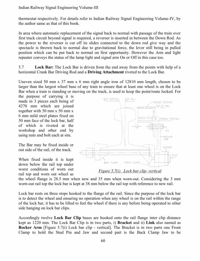
Indian Railway Signal Engineering Volume-III
60
thermostat respectively. For details refer to Indian Railway Signal Engineering Volume-IV, by the author same as that of this book. In area where automatic replacement of the signal back to normal with passage of the train over first track circuit beyond signal is required, a reverser is inserted in between the Down Rod. As the power to the reverser is cut off its slides connected to the down rod give way and the spectacle is thrown back to normal due to gravitational force, the lever still being in pulled position which can be put back to normal on first opportunity. However the Arm and light repeater conveys the status of the lamp light and signal arm On or Off in this case too. 5.7 Lock Bar: The Lock Bar is driven from the end away from the points with help of a horizontal Crank Bar Driving Rod and a Driving Attachment riveted to the Lock Bar.
Uneven sized 50 mm x 37 mm x 6 mm right angle iron of 12810 mm length, chosen to be larger than the largest wheel base of any train to ensure that at least one wheel is on the Lock Bar when a train is standing or moving on the track, is used to keep the point/route locked. For the purpose of carrying it is made in 3 pieces each being of 4270 mm which are joined together with 50 mm x 50 mm x 6 mm mild steel plates fixed on 50 mm face of the lock bar, half of which is riveted at the workshop and other end by using nuts and bolt each at site. The Bar may be fixed inside or out side of the rail, of the track. When fixed inside it is kept down below the rail top under worst conditions of worn out rail top and worn out wheel as the wheel flange is 28.5 mm when new and 35 mm when worn-out. Considering the 3 mm worn-out rail top the lock bar is kept at 38 mm below the rail top with reference to new rail. Lock bar rests on three stops hooked to the flange of the rail. Since the purpose of the lock bar is to detect the wheel and ensuring no operation when any wheel is on the rail within the range of the lock bar, it has to be lifted to feel the wheel if there is any before being operated to other side hanging on lock bar clips. Accordingly twelve Lock Bar Clip bases are hooked onto the rail flange inter clip distance kept as 1220 mm. The Lock Bar Clip is in two parts, i) Bracket and ii) Link also named as Rocker Arm [Figure 5.7(i) Lock bar clip - vertical]. The Bracket is in two parts one Front Clamp to hold the Stud Pin and Jaw and second part is the Back Clamp Jaw to be
Figure 5.7(i) Lock bar clip- vertical

61 Pramod P. Goel
accommodated by rail flange tightened together with a nut and bolt. A Stud Pin is riveted to the Front Clamp to hold the Lock bar clip secured by a washer and a split pin. The other end of the lock bar clip is provided with a pin to hold the Lock Bar 50 mm face. It is pertinent to note that the linear back and forth movement of the Lock Bar shall invariably be radial because of the Lock Bar Clips. Whenever a drive is required to be given to the Facing Point Lock along with the movement of the Lock Bar it shall be supported by the Radial Guide. The Radial Guide is designed such that to give radial lift equal to the lift of the lock bar hung on the Lock Bar Clips resting on either side of the Radial Guide recess with 200 mm throw. An Extended Bracket is accordingly fitted to the Lock Bar on 50 mm face using bolts and nuts. The Extended Bracket is connected to the first or second piece of the lock bar through Flange Connecting Rod using eye joint at the extended bracket and the Driving Attachment at the lock bar, to give strength to the system as well as to ensure integrity of the Lock Bar. The drive is given by the Lock Lever through Adjustable Crank connected to the Uneven Arm Crank through throw rod in between, the other arm of which is connected to the least far end Lock Bar piece through Driving Attachment [Figure 5.7(ii)]. As the Lock Lever is pulled it shall operate adjustable crank, which in turn shall operate the uneven arm crank, operating the Lock Bar moving the Extended Bracket and consequently driving the Lock Driving Rod by 200 mm. With each such movement the Lock Bar shall be lifted hanging on Lock Bar Clips and supported by the Radial Guide, to detect the wheel. If a wheel is detected it shall not be possible to operate the Lock Lever. The Lock Bar Clip is designed for the rocker arm to be leaning by 100 towards rail top to keep the distance between rail top and edge of the 37 mm face of the lock bar to be nearest possible. To ensure continuity, the drive to the Lock Bar is given at the rear end other than to which the function is provided if coupled with the Facing Point Lock. The Bar used as Lock Bar, Holding Bar, Fouling Bar or Clearance Bar etcetera when are required to be provided in the area with the check rail it shall not be possible to provide Lock Bar Clip, there being no space to accommodate them. As such in such a situation a Roller is attached to the 50 mm face of the lock bar, using pin with threaded end tightened to the Lock Bar with nuts, at intervals similar to the fixing schedule for lock bar clips. Roller Path with a semi circular top is fixed to the rail using nut and bolt. As and when drive to the Lock Bar is given from the cabin the lock bar shall lift and move through Roller Path top surface and fall back on other side akin to the movement across Radial Guide. As and when part of the lock bar falls within the area of check rail and part outside, only vertical Lock Bar Clip can be used to be in line with the area of check rail, there being no margin for any lateral movement between the lock bar and the check rail, for that part of the lock bar. The Holding Bar, Clearance Bar and the Fouling bar are used for different purposes to be discussed, are of same shape and size and derive their name based on the function by each of them.
5.7.1 Holding Bar: Usage of the Lock Bar defines its name as and when the Lock Bar is used to hold the route, it is termed as Holding Bar. The Holding Bar is used to hold the route. For this purpose one Holding Bar is provided at a distance of 180 metres from the signal of

Indian Railway Signal Engineering Volume-III
62
which the route is to be held. If the distance between the Holding Bar and the next facing point is more than 180 meters another Holding Bar shall be provided. However as and when the distance between the last Holding Bar falls less than 180 meters the next bar shall be the Locking Bar attached to the FPL. The route shall be held by movement of the train keeping the Holding Bars pressed. In this case the radial Guide is not required to be used but the Lock Bar Clips lift it through the
Driving Attachment driven with unequal armed right angle crank. The lift of the Holding Bar is used for detecting the wheel over the rail. The unequal arm of the crank is used to convert 200 mm stroke as reduced by the Adjustable Crank to be restored back to 200 mm. 5.7.2 Fouling Bar: When a train is received on the main line it should not be possible to change the point unless the last vehicle of the train is clear of fouling the adjoining track. A Fouling bar is provided connected to the trap placed on the rail opposite the trap point such that it shall not be possible to operate the trap point until the Fouling Bar pressed under the wheels on main line is cleared of the train concerned [Figure 5.7.2]. 5.7.3 Clearance Bar: The Clearance bar is connected on the same rail as that of to the trap point with the purpose of ensuring clearance of the point by the last vehicle of the train [Figure 5.7.2]. It should not be possible to operate the point till the last vehicle of the train has cleared the Clearance Bar so that the point is set normal only when the train is out of the Fouling Mark.
Both the situations under paragraph 5.7.2 & 5.7.3 are to avert side collision due to infringement of schedule of dimensions.
5.8 Compliance of operation to required norms: Most of the norms which are the standard dimension verses the tolerances allowed have been discussed while explaining the functions of different equipment and devices in preceding paragraphs these are added and summarised here: i) Stroke of 200 mm at the tail piece for point and lock operation getting reduced to 150
mm is considered to be within acceptable limits which is adjusted at the Adjustable crank to impart the 125 mm (4½") stroke on the lug of the William’s flexible stretcher bar.
ii) The standard opening of the point except thick web switches being 125 mm (4½") is acceptable up to but not less than 3½".
iii) The Spectacle which shall be absolute horizontal when having been replaced to normal is accepted as normal within the range of 50 of horizontal line.
iv) When fixed inside, the Lock Bar which shall be 28.5 mm below the rail top when rail and the wheel flange are new is allowed to be kept at38 mm below the rail top to cater for maximum wear and tear of the wheel flange and the rail top.
Fouling Mark
{
Fouling bar
Clearance bar
Figure 5.7.2 fouling &
clearance bars

63 Pramod P. Goel
v) The notch in the Split Stretcher bar is cut wider by 3 mm to the exact width of the lock plunger as permissible operational tolerance.
vi) Notch in the Lock slide in the point detector is cut 22 mm (1") which is wider by tolerance of 6 mm (¼") on either side against 10 mm width of the lock slide.
vii) Notch in the point slide is cut 13 mm, wider by 1.5 mm on either side against 10 mm thickness of the signal slide.
viii) Notch in the signal slide is cut 15 mm (5/8") wide as against 12 mm thickness of the point slide.
ix) Inter clip distance kept as 1220 mm for Holding/Lock Bar is approximate which can be readjusted with reference to sleepers placement obstructing fixing of the Lock bar Clip.
x) 53 mm wide notch is cut in the Stretcher Bar provided for Facing Point Lock with detection of travel as against 50 mm width of the lock plunger to maintain a tolerance of 1.5 mm on either side of the plunger.
5.9 Monitoring devices: No chances can be taken with the system of signalling with specific reference to Signals & Points. If the point lever is pulled to take the point to set for reverse but it has not corresponded with the lever, and the signal is taken Off, it shall cause the train to be received on a wrong route. Similarly i) if the lever is pulled to take the signal Off but it does not correspond to the lever, the train shall be kept waiting on the signal concerned keeping the Cabin Master totally ignorant causing undue detention to the train; ii) track occupancy has to be checked before receiving the train on the track concerned; and iii) when the signal is taken Off for reception of the train and the train moves and passes the signal, it shall not be possible to alter the route as set till the train reaches the destination, that is up to the next signal. Accordingly the detector for checking six signal slides, device to check for correct setting of points has been described under the preceding paragraphs and associated drawing numbered 5.3 with finer details shown in drawing numbered 5.3(i). The track vacancy verification by track circuits and the verification of the signal having been taken Off along with illumination of the signal lamp, both subjects have been discussed in Indian railway Signal Engineering Volume-IV by the author same as that of this book, may be referred to. Holding of the route is discussed in following paragraph.
5.10 Holding of the route until train reaches to the destination: Signal lever is last to be pulled for reception or departure of the train to keep the points, locks and Level Crossing Gates locked till the signal lever is put back to normal. Once the signal lever is put back to normal, the facing point lock lever, point lever, level crossing lock lever are rendered free to be operated. Accordingly it may be said that the route is held by the Cabin Master by not putting back the signal lever to normal or that the route is back locked only by the Cabin Master. In case when the automatic replacement of the signal by passage of the train is required, the signal shall be provided with a reverser and a track circuit just ahead of the signal to ensure putting back of the signal to normal by passage of the train, automatically. The Cabin Master is obliged to put the signal lever back in this situation along with automatic replacement of the

Indian Railway Signal Engineering Volume-III
64
signal to normal. Holding Bar is provided at an interval of not more than 180 meters (centre point to centre point) from the signal if the distance between the signal and the first facing point happens to be more than that. This shall be continued till the last facing point is cleared by the train maintaining maximum distance of 180 metres between the signal post and lock bar of the last facing point. This distance is worked out by way of experiments and experience gained by the signal engineers. This arrangement is, back locking the route mechanically. 5.11 Interlocking through Key Plunger Lock & E-Type Locks: So far the subject interlocking and locking of points is concerned the same has been discussed in preceding paragraphs of this book and also in Indian Railway Signal Engineering Volume-I by the author same as that of this book. However with respect to the yard interlocked to standard-I the interlocking and locking of point by key lock is discussed here. Interlocking shall be achieved by Mechanical/Electrical/Electronic means & locking of Point by Facing Point Lock or Point machine, in case of yard Interlocked to Standard-II and requirements being more stringent in case standards-III & IV. However in case of yard Interlocked to Standard-I, the interlocking shall be achieved by mechanical means using E-type lock and by Key Plunger Lock or Facing Point Lock. 5.11.1 Interlocking through Key Plunger Lock: The arrangement of Interlocking between points and signals is used at the stations interlocked to Standard-I, modified non-interlocked or for control of sidings. The system requires i) Key lock Facing Point H.P. Type and ii) ‘E’ type locks. The plunger of ‘E’ type lock which moves in and out of the Box of the Lock by operating key is termed as Lock Bolt. 5.11.2 Key lock Facing Point H.P. Type: Interlocking through Key lock is achieved by using Hand Plunger Lock and E-type Key assembly. The Hand Plunger Lock constituents are i) Lock one way, two way three way or four way, ii) Plunger, iii) handle for the plunger and, E-Type Lock. The cast iron Handle is fixed with nuts & bolts through the hole onto the outer side of the plunger to enable the plunger move in and out by hand. A notch is cut into the plunger to accommodate the Bolt of the E-type lock to keep the Hand Plunger fixed in position till it is kept locked. The cast iron Key Plunger Lock has channels cut to bear the Hand Plunger to move parallel to surface of its base, sliding through the notch cut into the Split Stretcher bar to lock the point in the position. If the points are required to be locked in normal as well as reversed position two lock tappets are riveted onto the Hand Plunger to detect and lock the normal and reversed positions of points. The tappet riveted on the upper surface of the plunger may detect normal setting of points and the one riveted at the dorsal side of the plunger for reversed setting of

65 Pramod P. Goel
points. Notches in the stretcher bar are cut accordingly. The E-type lock is fixed on the bracket (side wing) of the Key Plunger Lock, right angles to the Hand Plunger, using four bolts through the base of the E-type lock running through the threaded holes into the side wing of the Hand Plunger Lock. The cover of the E-type lock is secured by sealing with lead tablets, using braided wire. Key Lock facing Points, Hand plunger type are one way, Double, Treble and Quadruple. 5.11.2.1 Key Lock facing Points, Hand plunger type one way: This arrangement when it is required to keep the facing point locked for any one direction. As and when the route is required to be changed the key is released from the controlling end and used to release the point, change the setting and lock by the Hand Plunger. In this situation the key can not be released from the H.P. Lock there being no corresponding notch in the plunger. This type of key locking is used for controlling intermediate sidings and siding points in station section. 5.11.2.2 Key Lock facing Points, Hand plunger type Double: When the interlocking requires taking the signal Off only when the points are set to the desired position and locked. Under normal conditions when points are free to be operated, i.e. the hand plunger is out of the split stretcher bar, Lock Bolt shall be inside E-type Lock and as such the key shall be locked within. Considering that the point is required to be set to normal position only, it shall be possible to extract key out of the E-type lock only by setting the point in the required position pushing the Hand Plunger in, in alignment with the notch on the Hand Plunger with Bolt of the E-type lock, turning the key to move the Lock Bolt in and extracting the Key out of the E-type lock. This key shall be inserted into the E-type lock mounted on the concerned signal lever, rotate the key to take the Lock Bolt in, releasing the lever concerned to be pulled and take the signal Off. This shall lock the key inside E-type lock fitted on the said lever. It shall keep the point set and locked till the signal is put back to normal and the process is reversed. Two E-type locks shall be used onto the Hand Plunger lock if points are required to be locked in either position meant for two signals for the other route. Fixing the E-Type lock on the Lever in lever frame: The base of the E-type lock is fixed on a Wrought iron bracket through nuts and bolts. The bracket in turn is fixed on the concerned lever using nuts and bolts driven into holes on the lever, drilled for this purpose. When the key is inserted into the E-type lock fixed on the lever, and rotated to take the Lock bolt inside ‘E’ Type lock case and the lever is reversed, bolt of the lock shall be made to rest on the Back Stop fixed on the quadrant so as that it should not be possible to extract the key out of lock till the lever is put back to the normal position. Key Lock facing Points, Hand plunger type Treble & Quadruple are provided with three and four locks to achieve interlocking for more routes lead by the signals. In these cases the points are kept normally free and locked only when the signal is to be taken Off. 5.12 E-Type Key lock: E- type locks are in sizes i) 155 mm x 92 mm and ii) miniaturised size 100 mm x 75 mm.
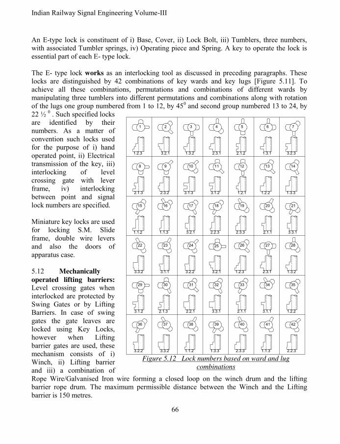
Indian Railway Signal Engineering Volume-III
66
An E-type lock is constituent of i) Base, Cover, ii) Lock Bolt, iii) Tumblers, three numbers, with associated Tumbler springs, iv) Operating piece and Spring. A key to operate the lock is essential part of each E- type lock. The E- type lock works as an interlocking tool as discussed in preceding paragraphs. These locks are distinguished by 42 combinations of key wards and key lugs [Figure 5.11]. To achieve all these combinations, permutations and combinations of different wards by manipulating three tumblers into different permutations and combinations along with rotation of the lugs one group numbered from 1 to 12, by 450 and second group numbered 13 to 24, by 22 ½ 0 . Such specified locks are identified by their numbers. As a matter of convention such locks used for the purpose of i) hand operated point, ii) Electrical transmission of the key, iii) interlocking of level crossing gate with lever frame, iv) interlocking between point and signal lock numbers are specified. Miniature key locks are used for locking S.M. Slide frame, double wire levers and also the doors of apparatus case. 5.12 Mechanically
operated lifting barriers: Level crossing gates when interlocked are protected by Swing Gates or by Lifting Barriers. In case of swing gates the gate leaves are locked using Key Locks, however when Lifting barrier gates are used, these mechanism consists of i) Winch, ii) Lifting barrier and iii) a combination of Rope Wire/Galvanised Iron wire forming a closed loop on the winch drum and the lifting barrier rope drum. The maximum permissible distance between the Winch and the Lifting barrier is 150 metres.
4241403937 3836
35343331 323029
282725 26242322
2119 2018171615
13 141211109
7
8
65431 2
1.2.3
3.2.2 2.3.31.3.3
1.2.23.1.1
1.1.2 2.2.31.1.33.3.2
2.1.12.2.13.1.2 2.1.3 3.3.1
1.3.22.3.11.2.33.2.1
3.3.1
3.3.2 3.1.1 3.2.2
2.1.12.3.32.2.33.2.11.1.31.1.2
1.3.31.2.21.2.13.1.23.1.32.3.22.1.3
3.2.31.3.12.1.22.3.11.3.23.2.1
Figure 5.12 Lock numbers based on ward and lug
combinations

67 Pramod P. Goel
5.12.1 Winch: Winch meant to give drive to the rope drum of the lifting barriers constitutes i) Post, ii) Pinion ‘A1’ & ‘A2’, two sets, iii) Pinion ‘B1’ & ‘B2’, two sets, iv) Gear Wheel, v) Locking Wheel, vi) Crank Handle, vii) Stopper, and viii) A pair of E-type locks with one and the same number. The crank handle is mounted on the shaft ‘1’ across the Post with Pinion ‘A1’fastened rigidly to it on driving side of the Crank Handle. Pinion ‘B1’ fastened to shaft ‘2’ just below the shaft ‘1’, is intermeshed with Pinion ‘B1’ onto which another pinion ‘A2’ is fastened rigidly butting against the pinion ‘B1’. The Pinion ‘A2’ drives the Gear Wheel, which works as Rope Drum, mounted rigidly on shaft ‘4’ running across the post. The shaft 4 bears Pinion ‘A3’ on the side opposite to the Gear Wheel. Just above this shaft, another shaft ‘3’ housed across the Post between the shaft ‘2’ and Shaft ‘4’ bears the pinion ‘B2’intermeshing with the Pinion ‘A3’. The shaft ‘3’ bears the Locking Wheel rigidly and butting against the Pinion ‘B2’, which is solid cast iron wheel with a cut to accommodate the Bolt of the E-type lock. An ‘E’ type lock is mounted on the Post inverted up side down such that the Bolt of the E-type lock is aligned with the notch on the Locking Wheel which shall occur only when the lifting barrier booms rest on associated stand. As the Crank handle is operated to rotate the Pinion ‘A1’ the corresponding intermeshed pinion ‘B1’ shall also rotate which in turn shall rotate the pinion ‘A2’ being housed on the same shaft as the one bearing pinion ‘A2’. The Gear Wheel shall also rotate as the Pinion ‘A2’ is intermeshed with it. The Gear Wheel shall also rotate the Pinion ‘A3’ along with it for the locking arrangement of the Winch. With the Pinion ‘B2’ intermeshed with the Pinion ‘A3’ the pinion ‘B2’shall also rotate making the Locking wheel also to rotate being on the same shaft. A stop Stud is fixed on the post as well as on the Gear Wheel such that the notch of Locking Wheel is aligned with the Bolt of the E-type lock as and when the both the studs but against each other. As the Bolt of the ‘E’-type lock is aligned against the notch of the Locking Wheel the Key shall be rotated to be extracted from the E-Type lock and inserted into the other E-type lock mounted on the Lock Lever in the laver frame. With the number of the lock being same as that one fitted on the Winch and the one fitted on the Lever, meant to lock the Lifting barrier Booms resting on their stands, reversing the Lock Lever it shall not be possible to release the key and operate the winch. The sequence to open the Lifting barriers for road traffic shall be reverse of what has been discussed above. 5.12.2 Lifting Barrier: While the Winch is meant to operate the lifting Barriers, the lifting barriers are provided to check the road traffic when a train is contemplated to cross the level crossing gate. The lifting barriers are of single barrier or double barriers on both ends of level crossing gate road, depending upon width of the road. Major parts of the Lifting barrier are: i) pair of Pedestals, ii) Boom, iii) Trunnion Bracket and the Drum, iv) Auxiliary Weight and Balancing Weight, v) Boom Stand with Boom Lock.

Indian Railway Signal Engineering Volume-III
68
5.12.3 Pedestal: Pair of cast iron pedestals is fixed with the nuts and bolts, bolts having been grouted into the Cement concrete foundation, a pit to house the extended end of the boom being its integral part. The top of the foundation shall be maintained at the rail level. A pair of brackets is fixed on top of both pedestals with nuts and bolts, to bear the axle about which the Boom shall be rotating up and down. 5.12.4 Boom: Booms used for mechanical Lifting barriers are tubular and are in two sections and two or more parts. The section-I is to be held by the Trunnion Bracket and Section-II is lighter and smaller in diameter joined with the Section-I to make it a continuous body. Tubular poles, which constitute Section-II of the boom are available in 10 metres (30'), 8 metres (24'), 6 metres (18') and 4 metres (12') sizes in one, two or more parts. The length of the boom is cut or added to the size depending upon the width of the road being protected by the Lifting Barrier. Both Booms must be equal in length and weight. Each Boom is painted with black and yellow bands to be distinctively visible to an approaching road vehicle. In addition a circular board painted red inscribed with STOP painted in white letters is also mounted on centre of both the Booms facing approach of the road. The diameter of Section-I of the boom is equal to the inside diameter of the Trunnion Bracket, tapered at the other end to match the diameter of the Section-II boom and extended so as to be joined to the Section-II boom either by welding the two together or by using sockets threaded inside to be joined to threaded socket fixed with the Section-II boom. The boom kept light in design has to be supported by the Stay rods one end of which is fixed onto the stand fixed on the Trunnion bracket. Lugs are fixed on the boom with nuts spaced to hold the threaded end of the Stay rods by nuts tightened on the threaded ends. 5.12.5 Trunnion Bracket: Trunnion Bracket is cast iron body in two parts, upper and lower, to sandwich the Axle passing through the Section-I boom, and sandwich the boom and tightened upper and lower parts together with bolts and nuts. The Boom shall rotate up amd down about this Axle. A pathway is casted in the lower part of the Trunnion Bracket to move the boom up or down by the roller fixed on the Rope Wheel Drum, which while rotating, having been operated by the winch, moves within the pathway of the Trunnion Bracket. The pathway is so designed that lifting and falling of the boom is regulated perfectly and comfortably by the winch. After the boom is erected vertical, the roller shall continue moving coming out of the pathway and rest against the Trunnion Bracket to keep the boom held in erected position as a safety measure to ensure that the boom does not fall on the road traffic of its own or due to mischief. The Rope drum is also provided with steps on its periphery to give lift to the lever connected with a hammer striking against gong and then falling back tipping from step to step, repeating the process till the Boom is closed against road traffic. This arrangement of mechanically
operated warning bell is unique and foolproof.

69 Pramod P. Goel
Similar to mechanically operated bell warning, the road light is also controlled through a bracket attached to the Axle of Trunnion Bracket, thereby converting the vertical movement of the bracket to horizontal and rotating the shaft onto which the Lamp bearing red and white lenses are provided along with corresponding coloured Targets, positioned opposite to each other of the lamp fixed in such a way that as and when the Boom is closed against road traffic the lamp shall display red light to the road traffic and when the Boom is open it shall display white light. 5.12.6 Auxiliary Weight and Balancing Weight: A cast iron bracket in two pieces is fixed around the rear end of the Boom Section-I onto which Auxiliary Weight is put using iron plates, held with nuts and bolts at the flat surface of the Bracket, away from the Axle. These iron plates may be put on top as well as at the bottom of the bracket as many as to make the Boom balanced about the Axle. To make the Boom perfectly balanced cylindrical cast iron pieces, with a hole in the centre of each, are inserted inside from the rear end of the boom Section-I, through a rod held by Axle at one end. The open end of the boom is closed, through which the cylindrical iron pieces were inserted, by a Cover with a hole in its centre, tightened in position by a nut on the rod protruding out of the Cover, thereby securing these cylindrical iron pieces in position. 5.12.7 Boom Stand with Boom Lock: The boom has to rest on the Boom Stand placed at the other end. To keep it secured it has to be locked in resting position. As the Key extracted out of the Winch, after closing the Boom, is inserted into the E-type lock of the Lever meant to lock the boom, and rotated to release the lever from its normal position, it is pulled/reversed to lock the boom by the slide lock inserted into the bracket fitted with the boom. The transmission could be wire or rod, while the wire transmission is no more acceptable because of its poor effectiveness, the rod is made to run using Cranks. A mild steel sheet shaped as Pole Guide is fixed on the top of the Boom Stand to guide and rest the boom down on the specified position to ensure that the lock Slide driven by the Lock lever enters into the bracket fixed on the boom.
Mechanically operated lifting barriers are being replaced with the power operated barriers on
fast pace.
*****

Indian Railway Signal Engineering Volume-III
70
TO
CA
BIN
AD
JU
ST
AB
LE
CR
AN
K
LOCK BAR
RADIAL
GUIDE
LEADING
STRETCHER BAR
1st FOLLOWING
STRETCHER BAR
2nd FOLLOWING
STRETCHER BAR
3rd FOLLOWING
STRETCHER BAR
TO
CA
BIN
AD
JU
ST
AB
LE
CR
AN
K
HORIZONTAL CRANK
Figure 5.7 (ii)
Layout- Facing point- 1 in 16 turnout B.G.

71 Pramod P. Goel
Indian Railway Signal Engineering Volume-III
Section-II
SYSTEM OF MECHANICAL SIGNALLING (DOBLE WIRE)

Indian Railway Signal Engineering Volume-III
72
CHAPTER- I
OPERATING DEVICES 1.0 The system of double wire signalling: Under the system of mechanical signalling, operation of points by rod has been most sturdy and trusted. However operation of signals by single wire had limitations of expansion and contraction of wire with the change in ambient temperature causing operational problems while the signalling also had been limited to two aspects affecting speed of the train due to poor communication of massage to the Loco pilot by two aspect signals. With the introduction of Double Wire system of signalling points and signals are operated with double wire forming a loop [Figure 1]. For signals the problem of expansion and contraction of wire with the change in ambient temperature is completely eliminated by use of a loop of wires wrapped upon the lever drum on lever end and on the drum of machine for signal, detector or point, on other end. Wire compensators are provided for each such loop to accommodate expansion and contraction of wire with the ambient temperature variations. However all advantages get set aside with the menace of un-predictive breakage of transmission wire, with un-predictive serious consequences. Accordingly engineers have explored all possible situations/conditions and have incorporated into design of signalling system which shall be seen progressively ahead. The system also provides multiple aspect signalling system using rotary signal machines. 1.1 Levers and Lever Frame: Major parts of Double wire lever are, i) Lever, ii) Drum, iii) Standard, iv) Interlocking arrangement and the Lever Frame. Actuation of Interlocking takes place by pressing of the Catch Handle. At this stage if the interlocking does not permit operation of the lever, it shall not be possible to press the catch handle at the initial stage. As the catch handle is pressed the 20 mm (¾") downwards movement is imparted to the Locking Plunger (Tappet) actuating interlocking. With
LEVER
ROPE
DRUM SIGNAL
MECHANISM
ROPE DRUM
Figure 1 Double Wire Loop
Figure 1.1.1.1(i) Direct type
double wire lever handle

73 Pramod P. Goel
pressing of Catch handle the centre of the arm of the Crank gets positioned in alignment to the centre of the axle of Rope Drum thereby keeping the crank stationary while the lever is operated full. As the lever is reversed moving 1800 about its hub and the Catch handle is released, another 20 mm (¾") movement is imparted to the locking plunger in the direction same as previous one to make it 40 mm (1½"). 1.1.1 Lever: Levers are of types i) Direct, ii) Clutch, iii) Trailable, iv) Rack and Pinion, v) Twin, and vi) Miniature, types. Besides, other levers are Three-to-One, which in effect is a crank for carrying adjustments and Auxiliary Lever to reset a declutched lever. All double wire levers are mounted on a Channel iron onto which the bolts are welded equally spaced such as to accommodate all levers side by side. The arrangement facilitates removal and installation of any lever without disturbing any other one except the interlocking. The interlocking frame is kept opposite to the person operating the levers. 1.1.1.1 Direct type lever: Direct type lever is an assembly of, i) Lever Handle, ii) Rope Drum 500 mm (20") stroke or 600 mm (24") stroke, iii) Catch Handle, iv) Link, v) Latch Rod, vi) Crank, vii) Standard, viii) Catch Handle Spring, ix) Number plate Bracket, x) Main Axle and, xi) Crank Axle Ring. This type of lever is used for working transmission which when broken or obstructed do not create unsafe conditions as such the Direct type levers are used for operating signals which do not have point detector in series of the wire run. When the wire is broken the signal machine shall stop in position with the signal having been thrown back to On if it was already not so. It is pertinent to note that the lever handle and the Rope Drum along with all accessories assembled together make the Lever. i) Lever Handle & Rope Drum: Lever Handle [Figure 1.1.1.1(i)] and Rope Drum [figure 1.1.1.1(v)] are fixed together to move in unison. The Lever Handle moves from normal position to reverse through 1800 imparting 500 mm (20") stroke to the wire loop one pulling and another being pulled. 500 mm stroke works well with distance up to 1200 metres only beyond which 600 mm (24") stroke Rope Drum is used. Two studs with threaded end are welded with the Lever Handle to hold the Rope Drum using hexagonal nuts tightened to the studs rigidly with the Lever Handle. The drum is mounted on the standard across holes between the Rope Drum and the Standard using the stud pin with a bronze bush to provide smooth surface between the Stud Pin and the orifice of the Lever & Standard. This is also required to eliminate wear & tear of the pin by replacing the bush. ii) Lever, Catch handle, Link and Latch Rod: The lever is in two sections, Lever Handle and a flat Mild Steel body. Catch Handle [Figure 1.1.1.1(ii)(b)] is attached to the lever through a hole in the lever, using pin across the catch handle and the lever. Next down below
Figure 1.1.1.1
(ii)(a) Latch rod

Indian Railway Signal Engineering Volume-III
74
the Bracket for number Plate is fixed on two holes made into the lever. A Bracket is fixed with the lever to hold the lower part of the spring connected to the Catch handle, on other end.
Another bracket is provided to house the Latch Rod [Figure 1.1.1.1(ii)(b)] secured under a cover plate. The stud is welded with the lever where two holes are shown to be fixed with the rope drum using nuts on the threaded end of the studs. The catch handle is hinged on the lever with a pin across the catch handle and the lever secured by washer on each end of the pin and split pin. A stop pin is welded to the Catch Handle to ensure its fixed movement as well as to prevent operator’s hand getting pressed in between the Catch handle and the Lever Handle. The Link from out side and the Spring between the space of catch handle are connected to the Catch Handle through a pin across all three. Other end of the Link is connected to the Latch Rod. The latch rod is connected to the arm of the crank at its other end. The ends of the spring terminate on Adjusting Nut & Bolt having an eye joint. Adjusting Nut & Bolt having an eye joint is fastened with the i) Catch handle though the pin across the hole of catch handle and ii) with the bracket fixed on the lever. The spring can be tightened or loosened as per requirement by rotating the nut fastened to the spring around the threaded end of the device attached for the purpose. When the catch handle is pressed, the latch rod is pulled causing the crank to turn about the axle thus imparting stroke to the Tappet. In this way the lever operation is made dependent upon tappet movement and if the tappet is locked under interlocking, it will not be possible to press the catch handle and disengage the Latch Rod Lug from the Quadrant of the Standard. The Link [Figure 1.1.1.(ii)(b)] is a plain Mild Steel strip with eye joint at its both ends one connected to the catch handle and other end connected to the Latch rod. The purpose of the Link is to impart drive to the Crank through the latch rod. The Latch Rod
holds the lever in normal or reverse position through the projected part ‘A’ working as Catch Block. As the latch Rod is lifted up with the pressing of Catch Handle against Lever Handle, it gets out of the quadrant of the Standard thereby permitting movement of the lever to either position. Other action of the Latch rod is to pull the arm of the Crank to actuate the interlocking when catch handle is pressed. The lever is rotated about the Rope Drum’s hub and is released when the lever is completely reversed or normalised.
LINK
SPRING
CATCH HANDLE
STOP PIN
ADJUSTINGNUT & BOLT
ADJUSTINGNUT & BOLT
Figure 1.1.1.1(ii)(b)
Catch handle assembly

75 Pramod P. Goel
The arrangement, as reviewed, is such that as the catch handle is presses against the Lever Handle i) the link gets pulled up and pulls the latch rod which in turn pulls the Crank arm to actuate the interlocking; ii) the spring gets under tension so as to bring the catch handle back to its normal position as and when released, iii) the stud ‘A’ which works as a Catch Block, an integral part of the Latch Rod, gets out of the Quadrant which is a part of the Standard so as to allow the lever to be operated, while simultaneously with the pull to the latch rod, the crank arm comes in alignment with the Rope Drum Axle on which the lever rotates, iv) it becomes possible to rotate the lever if the interlocking permits pressing of the catch handle. iii) Crank: [Figure 1.1.1.1 (iii)] The crank connected to the latch rod eye joint is fixed on the standard through a pin. The pin is held in position by a screw tightened through the quadrant of the standard. As the catch handle is pressed against the Lever Handle, the arm of the crank gets lifted pushing the other arm downwards about the hub. The hole in the arm of the crank connecting the latch rod is made slotted as while the movement of the latch rod is strictly linier the arm of the crank moves about the shaft radially allowing movement of the crank without flexing the latch rod. The crank is held in position on its axle shaft by a 16 SWG silico-manganese steel crank axle ring inserted into the axle shaft groove made for the purpose. iv) Standard and mounting of the Lever: Standard mounted on the Lever frame is the base to house the lever and the Rope Drum such that the handle of the lever is situated at a height comfortable to the Lever Man to hold and reverse it. Hole on the front projection and a slotted hole in the bottom of the base of Standard are made to be tightened with the 5/8" bolts welded to the lever frame. The lever frame is constructed of channel irons. The Rope Drum with a Bronze sleeve within the hole is mounted on the 1¼" diameter axle, secured by ¼" screw, through the right hand part, rope drum and the left hand part of the Standard to reduce friction. The Right hand and left hand directions shall be deemed with reference to the viewer facing the Standard, besides the left hand part of the Standard is shown dotted in figure number 1.1.1.1 (iv), as the rope drum is kept in between the right hand and left hand parts of the Standard. Crank is mounted on the right hand part of the Standard on to which the Quadrant M-N-O also
D.W. LEVER CRANK
LOCKING PLUNGER
CRANK HUB
Figure 1.1.1.1(iii) Crank
N
M
O
ROPE DRUM
AXLE HOLE
CRANK AXLE
HOLE
STANDARD
LEFT HAND PART
HOLES FOR
FIXING STANDARD
QUADRANT
STOPS FOR
RESTING LEVER
Figure 1.1.1.1 (iv) Standard for double
wire system of signalling
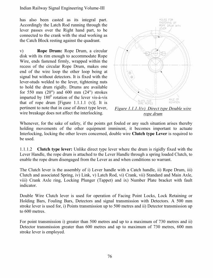
Indian Railway Signal Engineering Volume-III
76
has also been casted as its integral part. Accordingly the Latch Rod running through the lever passes over the Right hand part, to be connected to the crank with the stud working as the Catch Block resting against the quadrant. v) Rope Drum: Rope Drum, a circular disk with its rim enough to accommodate Rope Wire, ends fastened firmly, wrapped within the recess of the circular Rope Drum, makes one end of the wire loop the other loop being at signal but without detectors. It is fixed with the lever-studs welded to the lever, tightening nuts to hold the drum rigidly. Drums are available for 550 mm (20") and 600 mm (24") strokes imparted by 1800 rotation of the lever vis-à-vis that of rope drum [Figure 1.1.1.1 (v)]. It is pertinent to note that in case of direct type lever, wire breakage does not affect the interlocking. Whenever, for the sake of safety, if the points get fouled or any such situation arises thereby holding movements of the other equipment imminent, it becomes important to actuate Interlocking, locking the other levers concerned, double wire Clutch type Lever is required to be used. 1.1.1.2 Clutch type lever: Unlike direct type lever where the drum is rigidly fixed with the Lever Handle, the rope drum is attached to the Lever Handle through a spring loaded Clutch, to enable the rope drum disengaged from the Lever as and when conditions so warrant. The Clutch lever is the assembly of i) Lever handle with a Catch handle, ii) Rope Drum, iii) Clutch and associated Spring, iv) Link, v) Latch Rod, vi) Crank, vii) Standard and Main Axle, viii) Crank Axle ring, Locking Plunger (Tappet) and ix) Number Plate bracket with fault indicator. Double Wire Clutch lever is used for operation of Facing Point Locks, Lock Retaining or Holding Bars, Fouling Bars, Detectors and signal transmission with Detectors. A 500 mm stroke lever is used for, i) Points transmission up to 500 metres and ii) Detector transmission up to 600 metres. For point transmission i) greater than 500 metres and up to a maximum of 730 metres and ii) Detector transmission greater than 600 metres and up to maximum of 730 metres, 600 mm stroke lever is employed.
Figure 1.1.1.1(v) Direct type Double wire
rope drum

77 Pramod P. Goel
i) Lever handle, Catch handle, Link and Latch rod: While Catch Handle is not different as compared to the one used with direct type Lever handle, the Lever Handle not being directly attached with the Rope Drum, is different in design as compared to the Lever Handle used for direct type Lever [Figure 1.1.1.2 (i)(a)]. As and when there happens to be an obstruction in the wire run or the wire breaks there by creating a tension difference of more than 85 kg (186 lbs), between the pair of the wire loop, one wire of the loop connected to the operated equipment and Rope Drum of the lever shall be forced to move while the other wire as being loose shall allow the compensator lever weight to fall pulling the wires. Many more conditions may arise in case of wire breakage. However the tension difference of 72 kg (156 lbs) in the transmission wire shall not cause the Rope Drum to trip. As the spring connected to the Clutch Lever on its tail end and Catch Handle is adjusted such as to allow tripping and not tripping of the rope drum depending upon the given limits so as to make Clutch Lever getting lifted out of the rope drum notch meant not to hold the lever and the drum together or to hold it together, respectively. It is a possibility of signal or point machine getting moved there being uneven tension between the wires, thereby creating unsafe conditions such as point setting to a route not desirable to lead the train. If movement of point creates no road conditions, it should foul the interlocking by rotating the Rope Drum against Lever handle’s position. This shall happen by lifting of the Clutch Pawl out of notch of the Rope Drum against the tension of the spring, tension of broken or obstructed wire on the rope drum being higher. The condition is termed as ‘Tripping’. It is pertinent to note that the system is designed such as that the Tripping shall i) never take place during operation of the lever handle from complete Normal to complete reverse position or vice versa and till the Catch Handle is released by the operator, ii) cause to actuate the interlocking and iii) cause a stroke of 75 mm (3") which shall not affect the operated equipment such as point, signal or detector. First hole from the top, in the Lever handle is to hinge the Catch Handle. The second set of holes is to hold the Number Plate while a screw is tightened in the third hole to limit upward movement of the metal strip to make fault indicator plated hang out of the number plate assembly.
'B''A'
'Q'
Figure 1.1.1.2 (i)(a)
Lever handle Clutch
lever
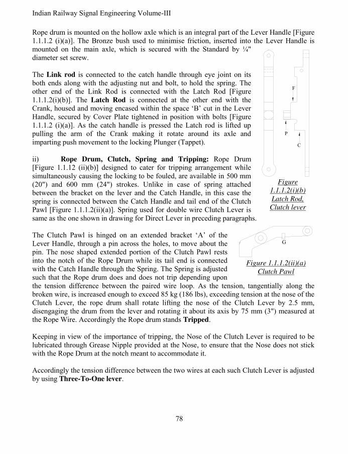
Indian Railway Signal Engineering Volume-III
78
Rope drum is mounted on the hollow axle which is an integral part of the Lever Handle [Figure 1.1.1.2 (i)(a)]. The Bronze bush used to minimise friction, inserted into the Lever Handle is mounted on the main axle, which is secured with the Standard by ¼" diameter set screw. The Link rod is connected to the catch handle through eye joint on its both ends along with the adjusting nut and bolt, to hold the spring. The other end of the Link Rod is connected with the Latch Rod [Figure 1.1.1.2(i)(b)]. The Latch Rod is connected at the other end with the Crank, housed and moving encased within the space ‘B’ cut in the Lever Handle, secured by Cover Plate tightened in position with bolts [Figure 1.1.1.2 (i)(a)]. As the catch handle is pressed the Latch rod is lifted up pulling the arm of the Crank making it rotate around its axle and imparting push movement to the locking Plunger (Tappet). ii) Rope Drum, Clutch, Spring and Tripping: Rope Drum [Figure 1.1.12 (ii)(b)] designed to cater for tripping arrangement while simultaneously causing the locking to be fouled, are available in 500 mm (20") and 600 mm (24") strokes. Unlike in case of spring attached between the bracket on the lever and the Catch Handle, in this case the spring is connected between the Catch Handle and tail end of the Clutch Pawl [Figure 1.1.1.2(ii)(a)]. Spring used for double wire Clutch Lever is same as the one shown in drawing for Direct Lever in preceding paragraphs. The Clutch Pawl is hinged on an extended bracket ‘A’ of the Lever Handle, through a pin across the holes, to move about the pin. The nose shaped extended portion of the Clutch Pawl rests into the notch of the Rope Drum while its tail end is connected with the Catch Handle through the Spring. The Spring is adjusted such that the Rope drum does and does not trip depending upon the tension difference between the paired wire loop. As the tension, tangentially along the broken wire, is increased enough to exceed 85 kg (186 lbs), exceeding tension at the nose of the Clutch Lever, the rope drum shall rotate lifting the nose of the Clutch Lever by 2.5 mm, disengaging the drum from the lever and rotating it about its axis by 75 mm (3") measured at the Rope Wire. Accordingly the Rope drum stands Tripped. Keeping in view of the importance of tripping, the Nose of the Clutch Lever is required to be lubricated through Grease Nipple provided at the Nose, to ensure that the Nose does not stick with the Rope Drum at the notch meant to accommodate it. Accordingly the tension difference between the two wires at each such Clutch Lever is adjusted by using Three-To-One lever.
F
P
C
Figure
1.1.1.2(i)(b)
Latch Rod,
Clutch lever
G
Figure 1.1.1.2(ii)(a)
Clutch Pawl

79 Pramod P. Goel
iii) Tripping of the Rope drum: The boss, ‘P’ portion of the Latch Rod, works as Catch Block to hold the lever in normal or reverse position as well as during this movement of the lever the Lug, an integral part of the Clutch Pawl, shall rest against the boss ‘F’ of the Latch Rod. As the boss ‘P’ of Latch Rod moves on the surface of the Quadrant ‘M’, ‘N’, ‘O’, with the lug ‘G’ of the Clutch Pawl resting against boss ‘F’ of the Latch Rod, it shall not be possible for the Nose of the Clutch Pawl to get lifted. This shall ensure that the tripping does not
take place during operation of lever from normal to reverse and vice versa. As the lever is set in either position, the gap of 19 mm (¾") is created between the Lug ‘G’ and the boss ‘F’, thereby allowing the rope drum to trip when conditions so warrant. As the Catch Handle is released with lever in either position, the Latch Rod is pulled down by the tension in the spring connected between the Catch Handle and the free end of the Catch Pawl, the boss ‘P’ of the Latch Rod shall rest against the Stop of the Standard. As the Rope Drum trips, it rests against the projections ‘H’ or ‘H’ on the Rope Drum on either side of the Lever Handle, depending upon the direction of rotation of the Rope Drum [Figure 1.1.1.2(ii)(b)] being 75 mm either way clockwise or counter-clockwise. However for first 7/8" tripping movement of the Rope Drum the Latch Rod shall not get any movement. As the Rope Drum moves further the Boss ‘P’ of the Latch Rod having being cleared of the projection ‘X’ on the rope drum, slides down between the ‘ab’ or ‘cd’ locking Cam and the projection ‘X’ held against surface ‘bf’ or ‘de’ respectively depending upon direction of movement of the Rope Drum. The Tripping imparts an upwards stroke to the Locking Plunger, simultaneously; The movement imparted to the latch rod is 3/8". While the extended portion ‘C’ of the Latch Rod rests against bottom of the cavity ‘B’ of the Lever Handle, thereby keeping the Latch Rod locked by boss ‘P’ held by surface ‘fb’ or ‘de’ of Rope Drum and boss ‘C’ pressed against bottom of the slot ‘B’ in the Lever Handle, thereby preventing the Catch Handle from being operated. This movement of the Latch Rod is opposite in direction to the movement by pressing of the Catch Handle. The Latch Rod cannot move to restore in normal position without resetting the drum, which can be done only after restoring the conditions causing tripping back to normal. In case the conditions arise for Tripping to take place but the interlocking does not permit to be fouled, being locked, the pulling of the Locking Plunger (Tappet) shall not take place as the rotary movement of the rope drum shall be limited to 7/8" only as against full 75 mm (3") when permitted by the interlocking conditions. This condition of Limited Tripping is not
CORED SLOT FORRECEIVING
THE AUXILIARY LEVER
HNOTCH FOR CLUTCH
'H'
E3
E2
716" NOTCH FOR COUPLED LEVERSSLOTS FOR WIRE ROPES
TO BE SMOOTH FINISHED
SPACE FORAXLE
E1
'a'
'b'
'c'
'd''e''f'
Figure 1.1.1.2(ii)(b) Rope Drum Clutch lever

Indian Railway Signal Engineering Volume-III
80
sufficient to transmit stroke for the point to operate being so small as to be absorbed by the double wire compensator.
Resetting of the Rope drum to be de-clutched, the Auxiliary Lever also termed as Clutch Resetting Lever, is used to reset the Rope Drum, inserting into one of the slots E1, E2 or E3, such as to bring the notch below the nose of the Clutch thereby getting the Rope Drum re-engaged with the lever handle, only after the cause of Tripping is attended to. A 500 mm stroke Clutch Lever is used for, i) Points transmission up to 500 metres, and ii) Detectors transmission up to 600 metres, while a 600 mm stroke lever is used for, i) Point transmission beyond 500 metres and up to a maximum of 730 metres, and ii) Detector transmission greater than 600 metres and up to maximum of 730 metres. iv) Standard, Crank, Main Axle and Crank axle: The Standard and the Crank used in Clutch type Lever are same as that used in case of Direct type Lever, discussed in preceding paragraph, while the Rope Drum is mounted on the hollow axle which is the integral part of the Lever Handle. Over all stroke imparted upon the Locking Plunger (tappet) is 40 mm (1½") as discussed in preceding paragraphs. v) Number plate with fault indicator: A number plate is invariably provided on each lever. In case of Clutch Lever while a number plate is fixed on the Lever Handle an indicator is also provided to warn the Lever Man of lever getting Tripped. A mild steel strip connected to the Clutch Pawl by means of a 1/8" pin, runs along the centre of the Lever Handle guided by the pin ‘Q’ on the Laver Handle, to be connected loosely to a Fault Indicator Shaft. As and when the Rope Drum trips the Strip and with it the Fault Indicator Shaft rotates while being pulled down, resulting in display of the Fault Indicator, hanging out of the number plate bracket. vi) Three-to-One
lever: This lever is meant for adjusting the tensions on which the rope drum should or should not Trip. It is pertinent to note that it is not used for operating any equipment and as such is kept outside lever Frame. The length of the lever is such that when inserted in the slot on the Rope Drum of the Clutch Lever it gives mechanical advantage of 3. Accordingly as a force of 85 kg (186 lb), is required to be applied, only 85/3 kg (186/3 = 62 lbs) shall have to be applied and the dynamometer shall read only the 1/3 value of the force applied on to the Rope Drum. Similar is
90°
THREE TO
ONE LEVER
MAIN AXLE
CATCH
HANDLE
SPRING
CATCH
HANDLE
LINK ROD
LATCH
ROD
DYNAMO METER
LEVER HANDLE
Figure 1.1.1.2 (vi) Three to one lever

81 Pramod P. Goel
the case with the force to be applied for lower limit of 72 kg (156 lb) on which the Rope drum shall not be made to trip. The dynamometer is similar to a spring balance. It may be noted that a dynamometer of measuring capacity of 100 lb shall be adequate for the purpose. The Force of 85/3 kg shall be applied as seen on the dynamometer scale and the tension of the spring connected between Clutch Handle and the Clutch Pawl is adjusted by rotating the Nuts and Bolts attached to the Catch Handle Spring, to be fixed at this position to allow the rope drum to trip. Similarly the adjustment shall be done to ensure that the Rope Drum does not trip at 72/3 kg force, as read on the dynamometer [Figure 1.1.1.2(vi)]. vii) Affect of tripping on Interlocking arrangements: The Rope Drum may trip either way when the Lever is set to normal or to reverse. The tripping of the Rope Drum shall invariably actuate the locking plunger except when the Locking Plunger (Tappet) is locked within interlocking frame by some other lever, as discussed in preceding paragraph. The
movement of the Locking Plunger (Tappet) due to tripping of lever shall be in the direction in
which the tappet moved last. For example if the Catch Handle is released when the lever is put to normal from its reversed position, the movement of the Locking Plunger shall be upwards i.e. in the direction of coming out of the locking frame. Now as and when the Rope Drum trips when lever is set to normal, the movement of the Locking Plunger shall be upwards i.e. in the direction of coming out of the locking frame which happens to be the direction same as that of last operation of the Locking Plunger. Notch in the locking plunger shall be cut tight if tripping is intended to foul the locking, however if tripping is not intended to foul the interlocking the length of the notch shall be cut elongated equal to the movement of the locking plunger due to tripping, so as not to actuate interlocking by the movement of the locking Plunger due to tripping of the Rope Drum. 1.1.1.3 Rack & pinion Lever: Operation of points with double wire especially not detected with double wire detector is not found to be safe in case of breakage of wire operating point. Accordingly Point, Facing Point Lock with or without Lock Bar as used under Single wire system of signalling, discussed under preceding chapters, are operated by 33 mm diameter mild steel rods is used under double wire system of signalling also operated by Rack & pinion lever. Major parts of the Rack & Pinion lever are, i) Rack & Pinion with a Roller [Figure 1.1.1.3(i)], ii) Lever handle with Catch Handle, Catch Handle Spring, Latch rod and Number Plate with bracket, iii) Standard, Main Axle, Crank, Crank Axle & Crank Axle Ring, iv) Locking Plunger (Tappet). The rod run remains same as used in single wire system of signalling running over trestles and rollers, Accommodating Cranks, Right Angle Cranks, Adjustable Cranks and rod Compensators etcetera.
HUBPINION DISK
PINION SECTOR
COUPLING END
RACK
Figure 1.1.1.3(i) Rack &
Pinion

Indian Railway Signal Engineering Volume-III
82
Accordingly the Rack and Pinion Lever is designed to work the operation of points, locks and lock bars by rods. The Standard [Figure 1.1.1.3 (iii)] is modified to accommodate an additional Roller to keep the Rack pressed against the pinion intermeshed with their teeth. The Pinion is used in place of Rope drum and is intermeshed with the Rack. The Crank, to actuate interlocking, is mounted on the Standard using the Crank Axle, similar to as in case of Direct Type Lever. The Pinion Sector is rigidly mounted on the Pinion Disk and the assembly is mounted on the Standard through Axle pin across the Pinion Disk and the corresponding holes in the Standard. The Rack shall also be placed in position simultaneously intermeshed with the Pinion. The Lever Handle used for Rack and Pinion Lever is similar to as the one used with Direct Type lever. The Pinion Sector
is fixed on Pinion Disk using nuts on the threaded studs welded to the lever handle [Figure 1.1.1.3(i)]. The Pinion Sector and Pinion Disk assembly is
i) mounted on the Standards about the Hub and ii) is connected to the lever Handle. The Catch
Handle is hinged to the Lever Handle. The Catch Rod loaded with Spring is connected with Catch Handle through eye joint [Figure 1.1.13 (ii)]. The other end of the Catch Rod which is threaded screwed into the threaded portion of the Latch Rod. The other end of the Latch Rod is connected to the Crank through eye joint. The Latch Rod encased within brackets moves along the Lever Handle. The projected part of the Latch Rod works as Catch
Block to release the lever handle from the Quadrant, for moving the Lever from normal to reverse and vice versa when lifted by the Catch Handle. The spring, when Catch Rod is lifted gets compressed between the Spring Seat and the nut on its lower part, to put it back when Catch Handle is released by the operator. To summarise, as the Catch Handle is pressed against the handle of the lever, the spring gets compressed. The Catch Rod is pulled, pulling the latch rod in turn to lift the arm of the crank as well as lifting the Catch Block, to release the Lever Handle from the quadrant allowing it to be reversed when it is normal and vice versa. The Crank shall in turn actuate interlocking having been terminated on the arm of Crank.
EYE
JOINT
THREADED
HOLE
CATCH
BOX
LATCH
ROD
EYE
JOINT
SPRING
SEAT
SPRING
CATCH
ROD
Figure 1.1.1.3(ii)
Catch Rod & Latch rod
QUADRANT
ROLLER
MAIN HUB
CRANK HUB
Figure 1.1.1.3 (iii) Standard Rack
& Pinion Lever

83 Pramod P. Goel
Coupling end of the Rack is joined with the rod terminated at the Vertical Crank fixed on the Inside Lead-Out. Further provisions of the rod run work on the same lines as discussed under chapter of single wire signalling. The stroke imparted by the Lever to the rod connected to the vertical crank is 12.5" which is reduced to 200 mm (8") by replacing 12" x 12" arm crank to 16" x 10.25" crank. This shall require the rib of the crank to be reduced by chipping off the metal to accommodate the solid joint for which the space was already available at 12" depth from the hub of the crank to enable 16" arm of the crank connect to the down rod.
1.1.1.4 Miniature Lever: The Lever Handle with a knob to hold it, does not operate a transmission, is mounted on the Standard. It controls functions through actuating interlocking. The lever is i) Two position type and ii) Three position type. The Lever Handle is extended to attach a plunger which moves up and down with pull and push of the Lever Handle interlocking/Interlocked to the Bolt of the E-type Lock/Locks, respectively while at the same time is attached to the Locking Plunger (Tappet) actuating interlocking concurrently. i) Major parts of the lever: Major parts of the lever are i) Standard, ii) Lever Handle,
Number plate, iii) Crank & Plunger, iv) Index Plate, v) Spring, and vi) Hardened Steel Ball.
a) Standard: Unlike Standard for other double wire levers, the Standard for Miniature Lever is radically different to bear Lever Handle mounted on the Standard though Pin in place of the crank. A Steel Ball-Knob of 12 mm (½") diameter, hardened, is provided for operation of the Lever Handle for convenience of the operator. The other end of the Lever Handle is connected to the Locking Plunger (Tappet).
b) Number and Index Plate: A number plate is fixed on upper side of the Standard while an Index Plate associated with lever indicates lever position be it Push, Middle or Pull.
c) Crank, Plunger, Spring and Ball: As already discussed in preceding paragraphs, the Lever Handle works as crank to operate the Locking Plunger (Tappet) connected through the hole made at the end of the Lever handle. However another strip is welded right angles to the Lever Handle to give, to and fro, movement to the plunger,
NUMBER PLATEKEY
PLUNGER
KEY LOCK 'E' TYPE
INDEX
PLATE
LEVER
HANDLE
STANDARD
PIN
BALL ON THE SPRING
TO KEEP THE PLUNGER
IN POSITION
Figure 1.1.1.4 Three position type Miniature lever

Indian Railway Signal Engineering Volume-III
84
which is held in last operated position by a ball pressed by a spring and is used to accommodate the Bolt of ‘E’ type lock for holding the route and effect interlocking.
ii) Two Position type Miniature Lever: The Lever rests in normal or reverse positions only. It controls Level Crossing gate, Siding, Inter-cabin slotting and Station Master’s Control etcetera by actuating interlocking when reversed. The Lever can handle only single control which may be received from out side or may be imparted by lever itself. The travel of the Locking Plunger (Tappet) is 40 mm (1½"). The Index plate depicts current position of one of the two, of the lever handle. Angular movement of the two position lever is 130 16' while that of three position lever is 60 38'. It is pertinent to note that the travel of the Locking Plunger (Tappet) of two position Miniature Lever is upwards as against travel of the Locking Plungers of levers other than Miniature Lever is down wards when either lever is operated from normal to reverse and vice versa. The Interlocking Plan (Dog Chart) shall be designed accordingly. iii) Three Position type Miniature Lever: The normal position of the Lever Handle is in middle of the other two positions, held in position by a ball pressed by a spring in case of three position miniature lever. The Index plate depicts three positions of the Lever Handle, up position termed as ‘Push’, middle as ‘Middle’ and down as ‘Pull’. Each operation of the Lever Handle imparts 20 mm (¾") stroke to the locking Plunger (Tappet) when pulled or pushed, the movement being half as compared to the two position lever. This lever being three position, is used to control conflicting requirements. The control may be received or granted by means of ‘E’ type locks fixed on the Standard. As the key of the ‘E’ type lock is released by other cabin or Station Master, released through the Key Transmitter releasing the Bolt of concerned ‘E’ type lock. This in turn shall enable to move the Miniature Lever Handle to middle/normal position releasing the concerned locked levers. In case the control is to be imparted upon out side of the cabin, the Lever Handle is pushed or pulled as the case may be, locking/releasing the lever/levers concerned, extract the key form the E-type lock on Miniature Lever to hold it in last operated position and transmit the Key to other cabin or the Station Master. [Figure 1.1.1.4]. 1.2 Lever Frame & Interlocking Arrangements: Double Wire Lever Frame is the assembly of, i) Levers, ii) Front and rear Lever supporting Channels each of 250 mm x 75 mm, held in position by Separators, iii) Stanchions to hold the lever-frame at the first floor level of the cabin, iv) 62 mm x 125 mm front and rear channels to bear Compensators, v) Two channels75 mm x 125 mm each for supporting the stanchions and for fixing the coupling device, vi) Girder of ‘I’- section for mounting the travelling trolley and the differential pulley block 100 x 175 mm to release and mount the double wire Compensator, and vii) Anchor bolts. 1.2.1 Interlocking arrangements: Interlocking arrangements are integral part of the Lever Frame consisting of i) Locking box, ii) Locking Plunger also termed as Tappet, iii) Locks, and iv) Locking bars.

85 Pramod P. Goel
Locking Boxes are available for 6 channels for 4 levers, 8 & 10 channels for 8 levers and for 10 levers.
Pitch of the levers is 125 mm, Stroke of the Locking Plunger (tappet) is 40 mm, Stroke of the Locking Plunger (tappet) when rope drum tripped is 12 mm, Pitch of the channel is 55 mm and width of the channel is 40 mm. Double wire lever frames of levers less than 20 can be supported on two stanchions one at either end. However frames for more than 20 levers up to 36 levers an additional stanchion shall be required in between. Levers beyond 36 to 56 shall require two stanchions in between the two provided at the either end. While this many levers are considered enough to operate a way side crossing station, single or double lines, by a central cabin, a bigger yard operated centrally may require about 80 levers. In such a situation four intermediate supports besides the end supports shall be required. Position of each such stanchion is worked out by dividing the number of levers by number of spans (space between two stanchions) added by one. For example, for a 20 lever frame one intermediate stanchion in between the end stanchions shall provide two spans to which added by one works out to be eleven to place the intermediate stanchion. Such space, under which the stanchion is erected cannot be used for wire or rod run, shall be provided with Miniature Levers. Tripping of the lever is a special feature of the system of Double Wire Signalling necessitating use of tight and loose locking.
1.3 Coupling of levers: As a special feature of double wire signalling, economy can be achieved by operating more than two aspects of one signal or operation of two signals, on the same post or two independent posts, using single transmission of wire common to two levers which have to be essentially placed adjacent to each other numbered consecutively. Drum Lock is provided to ensure that the Rope Drum does not trip during the other lever is being operated. The Coupling shall be i) Pull-Pull or ii) Push-Pull. 1.3.1 Pull-Pull coupling of levers: Pull-pull coupling of levers is used to operate signal in succession such as Home Signal 450 and 900 respectively to display two aspects in sequence, first aspect being by one lever and other being by second consecutive lever making the signal machine to move in the same and successive direction. Another example is of Outer and Distant Signal, i.e. two signals on the same post, for which when one lever is pulled, Outer signal shall be taken Off and when next consecutive lever is pulled the Warner signal shall be taken Off. It is pertinent to note that the in Pull- Pull and Push Pull, both arrangements, levers are required only to be pulled for taking the signal(s) Off, while the coupling arrangement is different for both. The signal Mechanism for such arrangement shall be 0-450-900 for Home Signal as discussed in preceding paragraph.

Indian Railway Signal Engineering Volume-III
86
1.3.2 Push-Pull coupling of levers: Push-Pull coupling of levers is used to operate signals on the same post, both of which are not required to take the signal Off, at any one time, making the signal machine to rotate in direction opposite to the first movement. The examples of Push-Pull coupling are, i) Lower Quadrant Main and Loop Line Home Signals, ii) Two loop line Home signals, iii) Starter and the Shunt Signal below it, iv) two Shunt Signals one below the other, and v) Home Signal & associated Calling-on signal on the same post. Signals on two different posts may also be operated, under Push-pull arrangement, subject to the length of the transmission between these two does not exceed 73 metre (80 yards). The signals may be, i) Two lower quadrant or upper quadrant starters located on different posts leading onto the same track, ii) Detector transmission, detecting the normal and reverse (conflicting) setting of the same pair of points, iii) 450 and 900 aspects of the same Multiple Aspect Upper Quadrant (MAUQ) signal where the two aspects conflict with each other such as a 3 position main line starter where the Caution aspect is utilised for shunting and Clear for starting, etcetera. 1.3.3 Coupling arrangement: Two, 12 mm (½") thick Mild Steel (MS) flats are welded to the channel which is a part of the lever frame, which is nearer to the lever-man, kept just below the concerned Levers, running downwards vertically, to be used as Coupling Device. Both MS Flats are coupled rigidly by welding the Tie Plate, at the other (lower) end of the Flats, making the assembly a monolithic block keeping both inside faces of MS flats by 150 mm (6") apart. Just opposite the Tie Plate, One Coupling Device Lever 500 mm (20") long is hinged using a Pin, with each Flat capable of revolving about the Pin. A Rope Wheel is fixed at the centre of Coupling Lever, which is 250 mm (10") as measured from the point of hinge of the lever, with a wire guard. A Reel is held with split pin at the loose end of the Coupling Lever. 1.3.3.1 Push-Pull Coupling arrangement: In case of Push-Pull arrangement the Coupling Device Levers ‘3’ & ‘4’ shall be kept drooping such that centre point of the axle of their Rope wheels are kept below by ¼th of the stroke of the Rope Drum, the level of point on which the Coupling Device Levers are hinged. As the Lever ‘3’ is pulled the Coupling Device Lever ‘3’ shall be lifted upwards by half of the Rope Drum stroke. Since the pull of wires on the Rope Wheel of Coupling Device Lever shall be on both ends, the pull shall be double of the amount of lift thereby
43
4
3
LEVER ROPE DRUM
REEL
CAST IRON WEIGHT
DOUBLE WIRE COMPENSATOR
PUSH 3
PUSH 4
PULL4
PULL 3
CO
UP
LIN
G D
EV
ICE
SIGNAL
MECHANISM
ROPE DRUM
LE
VE
R
CO
UP
LIN
G D
EV
ICE
Figure 1.3.3.1 Push-Pull coupling arrangement

87 Pramod P. Goel
making it 500 mm (20"). Accordingly the signal machine shall rotate as much as required to take the signal ‘3’ Off while keeping the other signal ‘4’ unaffected. As the Lever ‘4’ is pulled the Coupling Device Lever ‘4’ shall be lifted upwards by half of the Rope Drum stroke to impart another 500 mm stroke to rotate the same signal machine in reverse direction to operate the signal ‘4’ while keeping the signal number ‘3’ unaffected. It is pertinent to note that only one lever out of two shall be operated for one movement [Figure 1.3.3.1] 1.3.3.2 Pull-Pull Coupling arrangement: In case of Pull-Pull Coupling arrangement the Coupling Device Lever ‘1’ shall be kept drooping such that centre point of the axle of their Rope wheels are kept at ¼ th of the stroke of the Rope Drum, below the level of point on which the Coupling Device Levers are hinged. The pull wire from the Rope Drum shall be terminated on the Reel of the Coupling Lever ‘1’. the Coupling Device Lever ‘2’ shall be kept cocking such that centre point of the axle of it’s Rope wheel is kept at ¼ th of the stroke of the Rope Drum above the level of point on which the Coupling Device Lever ‘2’ is hinged. It is pertinent to note that the push (release) wire from the Rope Drum ‘2’ shall be terminated on the Reel of the Coupling Device Lever ‘2’. Accordingly the release wire of lever number ‘1’ shall pass through the Rope Wheel fixed on Coupling Device Lever ‘2’ and pull wire from the lever number ‘2’ shall be made to pass through the Rope Wheel fixed on Coupling Device Lever ‘1’ [Figure 1.3.3.2]. Under this arrangement as the Lever numbered ‘1’ is pulled the Coupling Device Lever ‘1’ shall be lifted upwards to the level of half the position at ¼ th of the stroke of the Rope Drum, above the level of point on which the Coupling Device Lever ‘1’ is hinged pulling the wire on the side of lever number ‘2’ thereby total pull becoming 500 mm or 600 mm stroke of the drum. As the lever number ‘2’ is operated in succession of lever number ‘1’, the Coupling Device Lever ‘2’shall come down by the same amount imparting additional same amount of stroke to the signal machine in the same direction as previous one, to take the next aspect of the signal Off. 1.3.3.3 Lever Drum Lock: While one of the levers is being operated under a coupling arrangement, which cannot be allowed to trip during operation as there is every chance of tripping because of tension difference created between the paired wire loop which may be beyond prescribed limit to trip the other lever of the coupling pair. To eliminate this situation the drum lock is provided on the Clutch Lever only. If one of the paired lever is clutch lever
12
12
LEVER ROPE DRUM
REEL
CAST IRON WEIGHT
DOUBLE WIRE COMPENSATOR
PULL 1
PUSH 1
PULL 2
PUSH 2
LE
VE
R
SIGNAL
MECHANISM
ROPE DRUM
CO
UP
LIN
G D
EV
ICE
CO
UP
LIN
G
D
EV
ICE
Figure 1.3.3.2 Pull-Pull coupling of levers

Indian Railway Signal Engineering Volume-III
88
and other is direct type lever, the Lever Drum Lock shall be provided on Clutch lever but if both levers are Clutch levers, the Lever Drum Lock shall be provided on both the levers. In case both levers are direct levers, no Lever Drum Lock shall be required. The Lever Drum Lock is actuated by pressing of the Catch Handle where as its device assembly is designed as “Coupled Clutch & Direct lever Left Hand or Right Hand”.
*****

89 Pramod P. Goel
CHAPTER- II
TRANSMISSION & DEVICES 2.0 Transmission & Devices: Transmission media for operation of signals and Double Wire Point machines is the combination of Galvanised Iron (GI) wire and Wire Rope using double wire compensators in the wire run. However points are also operated, using the 33 mm class ‘1’ steel rod, by Rack And Pinion lever. Compensators are used in rod transmission similar to as discussed on the subject of Single Wire system of mechanical signalling in preceding section-I of this book. Basic arrangement for Double Wire transmission is wire rope being wrapped around the Rope drum of the lever at one end and wrapped on the signal or point machine drum on the other end of transmission, to form a closed loop carried on the pulleys and pulley stakes kept compensated against the variation in length due to variation in ambient temperature. The double Wire Compensators are also instrumental in maintaining minimum tension difference in the pair of wires forming the loop using ratchet rod attached to the Double Wire Compensator.
2.1 Wire & Wire Run: Wire Rope and solid galvanised iron wires of different sizes are used in the transmission resting on double wire pulleys, expansion and contraction compensated by wire compensators, terminated on either ends of the loop on Lever Rope Drum and Signal machine or the drum of independent Rotary Detector. 2.1.1 Wire used for transmission: Wires used for transmission are, i) Wire Rope 6 x 19¼, ii) Solid Steel Galvanised Signal wire of 10 SWG, iii) Solid Steel Galvanised Signal wire of 8 SWG and iv) Solid Steel Galvanised Signal wire of 6 SWG. i) Wire Rope 6 x 19 ¼: Six strands each of 19 galvanised steel wires twisted to form one strand and six such strands twisted with a fibre core in the centre, form the wire rope of 6 mm (¾") nominal diameter. The tensile strength of such wire rope being 90 to 100 tons per square inch (140 to 160 kg per square metre) the breaking load is not less than 1720 kg (3800 lbs). The wire is used for wrapping around Lever Rope Drum, Signal and Point mechanism Drum and for running over the Rope Wheels where the angle of diversion in the alignment is more than 100. ii) Solid Steel Galvanised Signal Wire of 10 SWG, 8 SWG & 6 SWG: Solid Steel Galvanised Signal wire is used in straight alignments only, not being suitable to be run necessitating any bends such as wrapping around Rope drum or on Rope wheels for diversions. The 10 & 8 SWG Solid steel Galvanised Signal wire is used for low tension requirements such as signal control without detectors. Wire of 6 SWG is used for transmission needing higher tensile strength such as for Signals with Point Detector, Independent Detector, Point, Facing Point Lock and Holding bar transmissions.

Indian Railway Signal Engineering Volume-III
90
2.1.1.1 Joining of Wires: All joints between Solid Steel Galvanised Signal wires and those between Solid Steel Galvanised Signal wire and wire rope shall be soldered joints. The use of thimbles or split links, twisted or sleeve joints is strictly prohibited as the amount of tension on each wire shall cause the split link expand and give way. 2.1.2 Wire Run: Use of double wire to form a closed loop one end of which is wrapped around the Lever Rope Drum and the other end wrapped around the operated equipment which could be Signal Mechanism Drum, Point Mechanism Drum or independent Point Detector. To rotate the drum of the Mechanism for operating signal, point or independent Point Detector it is essential that the transmission imparted by the Signal Rope Drum reaches faithfully to the operated drum of the mechanism, for which it is essential that both wires of the transmission loop are kept taught with minimum loss due to friction of Double Wire Compensators and the pulleys enroute, theoretically leaving no tension difference between the two wires of the loop. With the use of Signal Mechanism, Multiple Aspect Signalling system could be achieved and made possible due to double wire transmission. This also eliminated the ill effects of variation in the length of wire with the variation in the ambient temperature automatically eliminated by use of Double Wire Compensators in the wire transmission. 2.2 Double Wire Compensator & formation of Loop: The basic purpose of a Double Wire Compensator (DWC) is to, i) maintain a given minimum tension to both of the wires which form a loop, and ii) neutralise the expansion and contraction in wire run consequent to the variations in ambient temperature. As and when a lever is operated, a tension difference is created between the two wires of the loop thereby creating a tensile force in between. The tension difference causes lifting of weight on the Lever of DWC Rope wire on which tension is increased and dropping of the weight on the other lever of DWC holding the Rope wire on which tension is decreased, which in effect shall absorb the tension difference without affecting the drum of the operated Mechanism. To avoid such a situation a Ratchet Rod is provided to engage both the DWC Levers thereby, forcing the tension difference between the two wires of the loop to make the associated mechanism Rope Drum to rotate. So far as the expansion and contraction of the wires in run is concerned it shall be equal on both the wires of the pair causing lifting or dropping of the weights on the lever of the compensator. However in any case if there is any difference in the tension of the two wires the ratchet rod shall not allow this to be so. The co-efficient of linear expansion of steel is taken as 0.000012 mm per degree centigrade and compensator strokes provided accordingly. 2.2.1 Major parts of the Double wire compensator: Major parts of the Double Wire Compensator are, i) Pedestal, which is fixed on ground, on channels, hedged by fencing to protect the innocent from being hurt in case of wire breakage, ii) 2250 mm x 75 mm (68.5" x 3") mild steel Compensator Lever to bear the Weight at one end and a Rope Wheel on the other end. Both levers are hinged on to the Pedestal top through an axle to rotate about, keeping 3:2 ratio of the Lever length, ratio ‘3’ (40-5/8") (being on weight side and ‘2’ (28") on rope wheel side, iii) Two Cast iron 95 kg (205 lb) weights fixed on each Lever imparting a tension of 68 kg

91 Pramod P. Goel
(153 lb) on each wire, held in position on the Lever tightened by a bolt. The position of the Weight on the lever may be adjusted to acquire desired tension on the wire, iv) One 1042 mm long Ratchet Rod measured between centre of the eye joint at one end and other end of the Rod; and Pawl assembly. Eye joint on one end of the Ratchet Rod is attached to the pedestal to move about a pin, passing through a paired set of Pawl assembly hinged on plates coupled to each other swivelled to move around, are rigidly attached onto both the Levers. As and when any of the weight on the lever is lifted, the Pawl shall get engaged by tilting towards, the Ratchet Rod not allowing this end of the lever to fall below, while keeping the other lever held in position it being attached to the same Pawl set, v) Rope wheels two sets each being in three in numbers, one on the top of the Pedestal, two at the base of the Pedestal. Accordingly as the double wire lever is operated and create a tension difference between the two wires of the loop, the Compensator Lever gets locked in position because of ratchet rod and pawl arrangement, to propagate the transmission to the operated equipment be it the Rope drum of Signal Mechanism, Point Mechanism or an independent double wire Detector. It is pertinent to note that the Ratchet Rod allows floating of the Lever when there is no tension
difference between the paired wires of the loop maintaining 1.5 mm clearance between Lock
Pawl and the Ratchet Rod and locks the Lever when there is any tension difference between two
wires. The floating of the lever is to compensate variations in length of wire due to variation in
ambient temperature.
2.2.1.1 Ratchet rod: Ratchet rod is hinged through eye hole with the pedestal to move about the pin. The operating part of the ratchet Rod is teethed, each of 600 & 300 dimension so as to engage the Pawl Piece against 300 slope of the tooth when a tension difference is created between paired wires of the loop while at the same time permitting free movement of the
GUIDE LINK
PAWL PLATE
PAWL PIECE
GUIDE BLOCK
GUIDE PIECE
HINGE
WIRE
BREAKAGE
MARK RATCHET ROD
GUIDE ROLLER
STOP
EYE HOLE
60 mm
28 mm
28 mm
60 mm
Figure 2.2.1.1(i) Ratchet rod & Pawl Piece assembly

Indian Railway Signal Engineering Volume-III
92
Compensator Lever against 600 angle of the tooth when the Compensator weights fall due to wire breakage or floating for compensation; see figure 2.2.1.1(ii). As the tension difference is created between paired wires one of the Compensator Lever shall be out of alignment and there by tilting the Pawl Plate engaging the Pawl to the tooth of the ratchet Rod. The 8 mm space between two teeth on the ratchet rod decides the Locking Stroke of the compensator which should not be more than 25 mm (1") as measured at the compensator. Guide Rollers between the set of Guide Links keep smooth movement of the Compensator Levers to which the Guide Piece is attached. The clearance between the face of the Lock Pawl and the teeth on the ratchet rod shall be 1.5 mm (1/16") on either side when the pair of wires is under equal tension. The Compensating stroke shall be adjusted such that the space on the Ratchet Rod between Wire Breakage mark and the End mark is kept clear beyond the Compensating stroke. 2.3 Type of Double Wire compensators: The double wire compensators are of, i) ‘A’ type single & coupled of 56" stroke, ii) ‘B’ type single & coupled of 72" stroke and iii) ‘C’ type coupled of 92" stroke. i) Stroke of Compensator vis-a-vis limits of operating distance:
‘A’ type compensator of single 56" stroke is suitable for transmission of, a) Points up to 730 metres (800 yards), b) Single signal up to 700 metres (800 yards) &, c) Detector up to 500 metres (580 yards). ‘A’ type compensator Push-Pull coupled 56" stroke is suitable for transmission of, a) signal transmission with detectors connected, thereto up to 800 yards (730 metres), b) detectors transmission up to 500 metres and c) signal transmission up to 800 yards (730 metres). ‘B’ type compensator of single 72" stroke is suitable for transmission of, a) signal transmissions greater than 730 metres and up to 1400 metres, b) detector transmissions longer than 500 metres and up to a maximum of 730 metres. ‘C’ type compensator coupled of 92" stroke is suitable for transmission of, a) Push pull Signal Transmission without detector, greater than 730 metres (800 yards) but limited to 1400 metres (1500 yards), b) Pull-Pull Signal transmission up to 1400 metres (1500 yards), c) Push-Pull Signal Transmission without detector greater than 730 metres (800 yards) but limited to 1400 metres (1500 yards).
WIRE BREAKAGE MARK
Figure 2.2.1.1(ii) Ratchet Rod dimensions (Metric version)
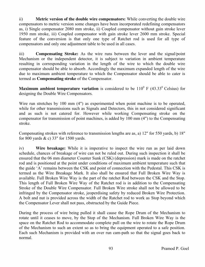
93 Pramod P. Goel
ii) Metric version of the double wire compensators: While converting the double wire compensators to metric version some changes have been incorporated redefining compensators as, i) Single compensator 2080 mm stroke, ii) Coupled compensator without gain stroke lever 1950 mm stroke, iii) Coupled compensator with gain stroke lever 2600 mm stroke. Special feature of the conversion is that only one type of Ratchet rod is used for all type of compensators and only one adjustment table to be used in all cases. iii) Compensating Stroke: As the wire runs between the lever and the signal/point Mechanism or the independent detector, it is subject to variation in ambient temperature resulting in corresponding variation in the length of the wire to which the double wire compensator should be able to absorb. Accordingly the maximum expanded length of the wire due to maximum ambient temperature to which the Compensator should be able to cater is termed as Compensating stroke of the Compensator. Maximum ambient temperature variation is considered to be 1100 F (43.330 Celsius) for designing the Double Wire Compensators. Wire run stretches by 100 mm (4") as experimented when point machine is to be operated, while for other transmissions such as Signals and Detectors, this in not considered significant and as such is not catered for. However while working Compensating stroke on the compensator for transmission of point machines, is added by 100 mm (4") to the Compensating stroke. Compensating strokes with reference to transmission lengths are as, a) 12" for 550 yards, b) 18" for 800 yards & c) 33" for 1500 yards. iv) Wire breakage: While it is imperative to inspect the wire run as per laid down schedule, chances of breakage of wire can not be ruled out. During such inspection it shall be ensured that the 06 mm diameter Counter Sunk (CSK) (depression) mark is made on the ratchet rod and is positioned at the point under conditions of maximum ambient temperature such that the guide ‘A’ remains between the CSK and point of connection with the Pedestal. This CSK is termed as the Wire Breakage Mark. It also shall be ensured that Full Broken Wire Way is available. Full Broken Wire Way is the part of the ratchet Rod between the CSK and the Stop. This length of Full Broken Wire Way of the Ratchet rod is in addition to the Compensating Stroke of the Double Wire Compensator. Full Broken Wire stroke shall not be allowed to be infringed by the Compensator stroke, jeoperdising safety by reduced Broken Wire Protection. A bolt and nut is provided across the width of the Ratchet rod to work as Stop beyond which the Compensator Lever shall not pass, obstructed by the Guide Piece. During the process of wire being pulled it shall cause the Rope Drum of the Mechanism to rotate until it ceases to move, by the Stop of the Mechanism. Full Broken Wire Way is the space on the Ratchet Rod to accommodate complete pull on the wire to rotate the Rope Drum of the Mechanism to such an extent so as to bring the equipment operated to a safe position. Each such Mechanism is provided with an over run cam-path so that the signal goes back to normal.

Indian Railway Signal Engineering Volume-III
94
The Broken wire stroke can be worked out as sum total of i) Stretch in the intact wire when its tension increases beyond 68 kg taken as 100 mm (4") for heavy functions like points, but is not considered for other lighter functions, ii) 75 mm shall be added towards signal transmissions longer than 730 metres, iii) maximum movement of the drum, iv) tripping of the lever when free & not locked, by 38 mm, and v) 50 mm allowance for over sized 600 mm stroke Rope Drum, which is enhanced by 100 mm if it is Push-Pull arrangement without Detectors. This is standardised as 387 mm (under metric system) [2.2.1.1(ii)]. 2.3.1 Inside Lead-out: One Compensator each is installed on the compensator channels inside the basement of the cabin, below each lever with wire transmission. A Chain Pulley is mounted capable to roll across, on the Girder running parallel to and below the lever frame to which the Chain can be attached through a hook holding the Compensator Lever at its weight side end where a notch is cut to facilitate firm holding by the Chain Pulley, while lifting the Compensator Lever for adjustments. This facilitates accurate adjustments of the Compensator. Each Compensator is adjusted to the current ambient temperature as measured by keeping the thermometer near a metal surface in vicinity. A table numbered as 2.3.1, provides the distance from the Stop up to the Guide Block (extreme end of the Guide Plate) to be positioned, on the Ratchet Rod. This length shall be read on the table at the cross points of column bearing temperature and row bearing the length of the corresponding transmission. The ambient temperatures are given in the table in steps of 50 as such the temperature measured shall be modified to be nearest slab on the table for the purpose of adjustment. For example the length between the Stop and the Guide Block works out to be 567 mm when the current ambient temperature as read on the table after adjustment is 320 and the length of transmission being referred as 1000 Metres. Coupled ‘C’ class compensator has additional parts for increasing the stroke is i) Gain Stroke lever and ii) Link. 2.3.2 Gain Stroke Lever & Link: Coupled, type ‘C’ compensator is provided with an additional feature of Gain Stroke Lever. The Gain Stroke Lever, which is a MS flat, is hinged midway its length, onto the vertical piece of the Pedestal. A Rope Wheel fixed at its one end replacing the Rope Wheel provided at the Pedestal base, and a Link hinged at the other end of the Gain Stroke Lever. The other end of the Link has a loop hooked to the pin fixed on to the Compensator Lever, on its Rope Wheel side. As the Compensator Lever rotates about the pin holing it onto the pedestal, the Link also moves up an down along with it, in-turn making the Gain Stroke Lever rotating about the pin on which it is mounted, thereby making the Rope Wheel mounted on the other end of the Lever also

95 Pramod P. Goel
move up or down opposite the movement of the Link. As the Link pulls the Gain Stroke Lever up, the Rope Wheel on the other end shall go down and vice-versa. In case of wire broken conditions, as the Weight shall fall to cause the Compensator Lever other end rise, which in-turn shall pull the Link up thereby pushing the Rope Wheel on the Gain Stroke Lever down, consequently gaining the wire stroke.
TR
AN
SM
ISS
ION
LE
NG
TH
IN
ME
TE
RS
DISTANCE BETWEEN STOP AND THE GUIDE BLOCK ON RATCHET ROD AT TEMPERATURE IN CENTIGRADE VERSUS LENGTH OF TRANSMISSION
20 70 120 170 220 270 320 370 420 470 520 570 620 670
100 551 549 548 546 544 542 540 539 537 535 533 531 530 528
150 557 555 552 549 547 544 541 539 536 533 530 528 525 522
200 564 560 557 553 549 546 542 539 535 531 528 524 521 517
250 570 566 561 557 552 548 543 539 534 530 525 521 516 612
300 576 571 566 560 555 549 544 539 532 526 520 513 507 501
350 583 576 570 564 557 555 545 539 532 526 520 513 507 501
400 589 582 575 567 560 553 546 539 531 524 517 510 503 495
450 595 587 579 571 563 555 547 539 530 522 514 506 496 490
500 602 593 584 575 566 557 548 539 530 521 512 503 494 485
550 608 598 588 578 568 558 548 539 529 519 509 499 489 478
600 614 603 593 582 571 560 549 539 528 517 506 495 485 474
650 620 609 597 585 574 562 550 539 527 515 503 492 480 468
700 627 614 602 589 576 564 551 539 526 513 501 488 476 463
750 633 620 608 589 579 566 552 539 525 512 498 485 471 458
800 639 625 611 596 582 567 553 539 524 510 485 481 467 452
850 646 630 615 600 584 569 554
539
523 508 493 477 462 447
900 652 636 620 603 587 571 555 539 522 508 480 474 458 441
950 658 641 624 607 590 573 556 539 521 504 487 478 453 436
1000 665 647 629 611 593 575 567 539 521 503 486 467 449 431
1050 671 652 633 614 595 576 557 539 520 501 482 463 444 425
1100 677 657 638 618 598 578 558 539 519 499 479 459 440 420
1150 683 663 642 621 601 580 559 539 518 497 476 456 435 414
1200 690 668 647 625 603 582 560 539 517 495 474 452 431 409
1250 696 674 652 629 606 684 561 539 516 494 471 449 426 404
1300 705 679 656 632 609 585 562 539 515 492 468 445 422 398
1350 709 684 660 636 611 587 563 539 514 490 466 441 417 393
1400 715 690 665 639 614 589 564 539 513 488 463 638 413 387
Table number 2.3.1 Adjustment of compensator

Indian Railway Signal Engineering Volume-III
96
Care should be taken to ensure that the floating wheels on the Gain Stroke Lever of compensator are lifted to the highest position. The end of the gain stroke lever shall be firmly tied to the compensator pedestal and the wire rope run out. However, it is imperative that the gain stroke lever is untied as soon as the transmission has been connected: otherwise the stroke of the compensator will be considerably reduced and broken wire protection will not be fully available. 2.3.3 Single Wire-loop Compensator: The Compensator is fixed on the channel, using two bolts and nuts with three pairs of rope wheels, including the one used on the compensator lever, while a compensator for coupled transmission uses four bolts and nuts each using three pairs of 12" diameter Rope Wheels, including the pair of Rope Wheels used on the Compensator- Levers. The extra pair of 11" diameter Rope Wheels is provided being compatible to the diameter of the axle of the Compensator Levers. The pair of wires dropping down from the Rope Drum of the Lever runs around the Rope Wheels fixed on the pedestal base plate, to the Rope Wheels fixed at the end of the Compensator Lever and then to Rope Wheels fixed on the pedestal base positioned lower and extended then the other Rope Wheel. The pair of wires thus brought to the level of Out Side Lead Out is wired around the Horizontal Rope Wheels to be taken on pulleys/ pulley stakes, terminating wrapped onto the end Mechanism Rope Drum, which may be Signal Mechanism without detector or an independent Detector forming a closed loop. Normally the wire length used shall be in one piece without joints between the Lever Rope Drum and the
outside lead-out.
2.3.4 Coupled Wire-loop Compensator: Wire Rope
dropping from the Coupled Levers eventually has to pass through the Coupling Device Levers which are spaced same as that the levers concerned. The coupling arrangement also necessitates use of a pair of rope wheels mounted on the same axle as that of Compensator Lever. Accordingly the Rope wheels provided at the end of the Compensator Lever face inside. These Rope Wheels used are of 11" & 300 mm (12") diameter to avoid rubbing of wires with each
Figure 2.3.3 Single Wire Loop Compensator
RATCHET ROD
ROPE WHEEL 12"DIAMETRE
COMPENSATOR LEVER
WEIGHT
HOLDING BOLT
COMPENSATOR PAWL GUIDE
PADESTAL

97 Pramod P. Goel
other. Three pairs of 300 mm (12") wheels are used similar to as being used for single lever transmission. 25 mm (1") diameter pin is used for 300 mm (12") diameter wheel. However as the Compensator Levers are born on 1.25" diameter pin, the 11" diameter Rope Wheel hole has to be of same diameter. For wire run arrangements up to Inside Lead-out refer to Chapter-I of this section. Rest of the wire run shall be similar to the Single wire loop as described in preceding paragraph. 2.4 Outside Lead-out: The lead out channels are bolted on 'A' type foundations which are grouted with Cement, Sand and Gravel aggregate in the ratio of 1:3:6, underground aligned to the required array of the Rope Wheels. Horizontal Rope Wheels are mounted on these Channels with bolts and nuts, making an array inclined both sides from centre towards wall of the cabin (arrowhead formation), such as to provide 5" space between the wires coming out from the Compensator on Inside Lead-Out in accordance to the lever pitch; and to provide 2.5" separation between paired outgaining wires to maintain a separation between wires leading out from the Rope Wheels to the Pulleys. Single Rope Wheel is provided for coupled transmission, separation of wires leading out from inside lead-out being more and paired Rope wheels are provided for Single (uncoupled) transmission. 2.4.1 Pulleys, Pulley Stakes, Wheels: Inter pulley space is specified to i) never be more than 15 metres (45 feet) when transmission is for operation of point, lock and detector or when it is mixed with signal transmission, ii) not more than 20 metres (60 feet), when transmission is for signals, which can be reduced suitably depending upon curvature in alignment. 2.4.1.1 Pulley Stakes: 1200 mm (4') long and 65 x 65 x 6 mm (2.5" x 2.5" x 0.25") right angle Pulley stake is provided with a crossbar at its top, making ‘T’ formation, to hold two-way pulleys on either side of the crossbar. If a four way bracket is required, another cross bar below the upper one shall be fixed. One way pulley shall be fixed on the pulley stake with two bolts and nuts. For more number of pulleys a Bridge Stake shall be provided. The Bridge Stake is the combination of two Pulley Stakes joined with a Cross Bar having holes to bear the pulleys, joining the Pulley Stakes at the top. While 6 ways, 8 way and 10 way pulleys shall be accommodated in one tier, 12 way, 14 way, 16 way, 18 way and 20 way Pulleys can be accommodated in two tiers. Two tiers shall be spaced by 7 ¼" between the two Cross Bars. While the wire shall be made to run straight without any undulations, as and where a curve is encountered, the angle pulleys shall be provided and tightened having positioned with the wire alignment. Pulley stakes shall be pierced into ground observing Schedule of Standard Dimensions (refer Indian Railway Signal Engineering Volume-I by the author same as that of this book).

Indian Railway Signal Engineering Volume-III
98
As and when a diversion of more than 100 is required to be taken, the wires shall be made to run on Rope Wheel and the Rope Wire alignment shall be tapered gradually, between pulley and the Rope Wheel such that there is no tendency for the wire to slip off the groove. As and when the transmission is required to pass through road of level crossing gates the wire shall not rub against walls, protecting covers and while crossing the track it shall be protected by channels to avoid rubbing against ballast or sleepers. 2.4.1.2 Wire Pulley: Single or Double
Pulley Wheel, encased in a bracket held in position with a pin, makes a Wire Pulley set. The arrangement is designed such that the rope wire does not slip out of the pulley. The bracket is fastened tight to the crossbar or the Bridge Stake using bolts and nuts for straight
run. To cater for diversions within 10
0 of main alignment a lug, also called as Intermittent Link,
one end of which is bolted tight to the Cross Bar or the Bridge Stake. The pulley is bolted with the other end of the link and allowed to take its position with the wire run and then is tightened firm to the link [figure 2.4.1.2]. 2.4.1.3 Rope Wheel: A Rope Wheel is mounted on a Base with a Guide. The guide is meant to prevent the Rope Wire from being slipped off the groove of the Rope Wheel. More than one Rope Wheels may be mounted on one base. The Guide can be rotated about the axis of the Rope Wheel to be fixed in position for best performance. Slipping of the Rope Wire may take place due to slackness in the wire run or due to angle of paving in or paving out of the plane of the Wheel, is more than it can be accommodated by the groove of the Wheel [Figure 2.4.1.3] The Rope Wheel shall be of 6-5/8" diameter. i) Angled Rope Wheel: Angled rope wheel is put on bases with its hub inclined so as to enable the wire being run across unequal levels inclined to horizon, to avoid slipping off of the wire rope from the wheel.
ii) Diversion wheel: [Figure 2.4.1.3] Diversion to the main alignment more than 100 and up to 300 requires Rope Wheel of 195 mm (7.75") diameter. However for diversion beyond 300, the 225 mm (8-7/8") diameter Rope Wheel shall be used. There being a force directed angular to the middle of the angle of diversion, the Rope wheel shall be fastened on to the ‘A’ type Cast Iron foundation
Figure 2.4.1.2 Wire Pulley (double)
Figure 2.4.1.3 Rope Wheel

99 Pramod P. Goel
which in turn is embedded into the earth and grouted with cement, sand and gravel aggregate. As and when the number of wheels to be fixed is more to form an array, the Rope Wheels shall be fixed on iron channels which in turn shall be mounted on the Cast Iron foundations embedded into earth and grouted with cement, sand and gravel aggregate. Diversion wheels are available in single, one pair and two pair assemblies. iii) Wheel Guide: [Figure 2.4.1.3(iii)] During operation of lever the tension is increased in one wire and slackened in the other wire of the loop creating tendency for the slackened wire to slip off the groove of the Rope Wheel. Being a regular feature, a foolproof arrangement is provided using Wire Guide. Under normal conditions the wheel hub serves as the wire guide. One Wire Guide is used for the wheel when provided on diversion less than 250. However two Wire Guides shall be used on the Rope Wheel put on diversion beyond 250. The clearance between Wheel Guide and the wheel edge shall be not less than 1.5 mm (1/16") and not more than 2 mm (3/32"). The Wheel Hub also works as an additional Wheel Guide on other end.
COLLARROPE WHEEL
GUIDE SUPPORT
GUIDE CAP
DISK WITH SLOTS
BASE
SLOTS
Figure 2.4.1.3(iii) Wheel Guide (left) & Wheel of Rope Wheel (right)
Two or more wheels may be inserted in one Rope Wheel by using appropriate Collars. The Guide may be positioned by rotating over the Slots provided in the disk on the top and Guide Support in the bottom. 2.4.2 Spacing & identification of joints: Entanglement of joints with each other or with the rope wheel is most unwanted feature. The factors which affect the joint entanglement are i) Temperature variation, ii) Adjustment of transmission to suit the use of over sized Lever Drum iii) Lever operation with 20" or oversized Lever Drum, and iv) Wire breakage. In case of increase in ambient temperature the joints move towards the compensator and vice-versa. However this does not affect the inter-se status of the joints as these joints move together with the temperature variation. As the Lever is operated, one of the paired wires of the loop moves in direction opposite to the other wire of the same loop. Under situations when the joints in the wire move approaching

Indian Railway Signal Engineering Volume-III
100
each other, there shall be chances for entanglement of these two but when these move opposite to each other there will be no situation for entanglement of these joints. Any entanglement of the joints with each other, Pulley or Rope Wheel may lead to unsafe conditions, resulting in points gaping, signals Off or drooping, detector failing to detect the point necessitating working out space between the joints. 2.4.2.1 Spacing & identification of joints; transmission of Single lever: Double the lever stroke added with 200 mm as safety margin shall be kept as minimum distance between two such joints when lever is normal. This is true for Push–Pull coupling of wires also. In case of single lever and Pull-Pull transmission, joints in the pull wire, when lever is normal, shall be painted red and those in the return wire painted black for easy identification. 2.4.2.2 Spacing & identification of joints; Pull-Pull transmission: In case of Pull-Pull transmission, two levers are operated one after the other resulting in the joints moving towards each other, each by twice the lever stroke and therefore, the distance between the ends of the wire ropes of such transmission shall be four times the lever stroke added with 200 mm & 150 mm as safety margins. Joints for Push-Pull transmission shall be painted white and with the number of lever pulling the wire, when connected Normal to Reverse, painted in black. However under the arrangement of transmission other than Push-Pull joints in the pull wire with the lever normal should be painted red and those in the return wire painted black for identification. 2.4.2.3 Spacing of joints with respect to Rope wheel: The length of the Rope wire for use at the Rope wheel is kept clear of the wire joint added with the margin for the Compensating stroke variation, since joints move towards or away with the drop & rise of the weights of the compensator with the increase and decrease in the ambient temperature. The maximum range of temperature for entire length of wire is catered for every joint irrespective of its location and distance from neutral point. 2.4.2.4 Spacing of joints when Adjusting Screw is provided in the transmission: Wire adjusting screw is provided i) near Lead-Out & ii) near the function which could be Signal Mechanism, point Mechanism or Detector, and iii) function (such as Detector or a Signal) in between the outside Lead-Out and the terminal function. Since the function shall have to be maintained as neutral point, where no movement shall be allowed to occur due to Ambient temperature variations, the adjustment shall be done near the function only and never at the
Lead-Out. 2.5 Detector, Signal and Point Machines in the wire transmission & Adjustable
screws: With the double wire system of operation the lever in the cabin and the Rope Drum of signal Mechanism, point Mechanism and the Detectors are essentially required to be circular drum, forming a closed loop of combination of rope wire and solid GI wire. Accordingly the Rope Drum of the lever, when operated, makes the Rope Drum of signal Mechanism, rotary
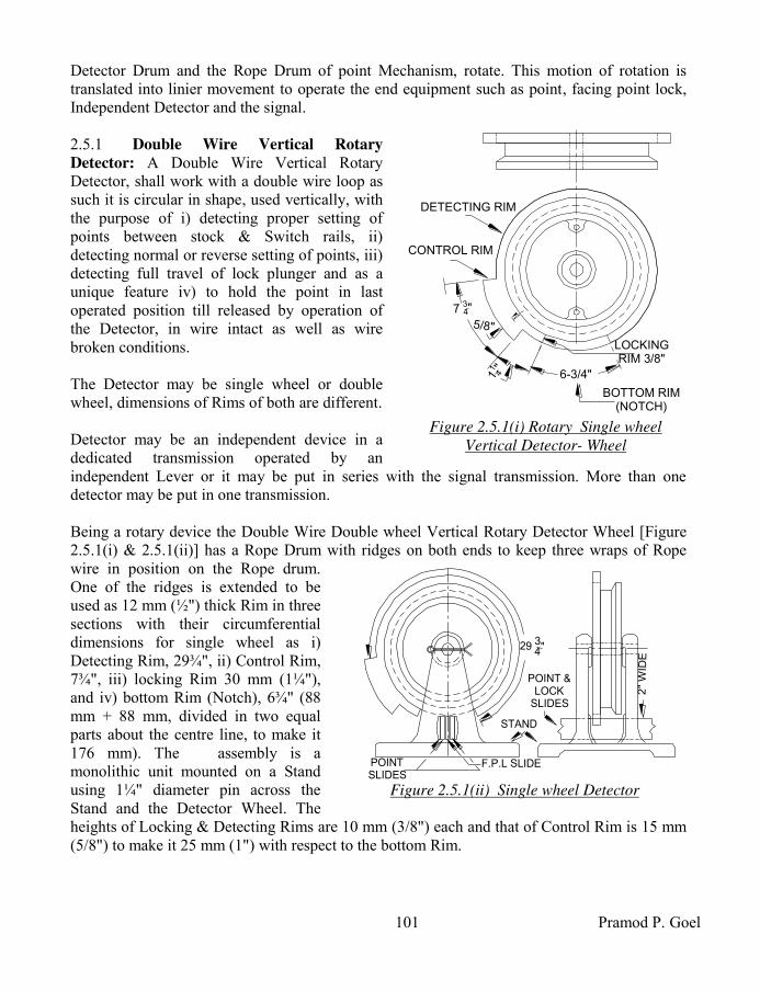
101 Pramod P. Goel
Detector Drum and the Rope Drum of point Mechanism, rotate. This motion of rotation is translated into linier movement to operate the end equipment such as point, facing point lock, Independent Detector and the signal. 2.5.1 Double Wire Vertical Rotary
Detector: A Double Wire Vertical Rotary Detector, shall work with a double wire loop as such it is circular in shape, used vertically, with the purpose of i) detecting proper setting of points between stock & Switch rails, ii) detecting normal or reverse setting of points, iii) detecting full travel of lock plunger and as a unique feature iv) to hold the point in last operated position till released by operation of the Detector, in wire intact as well as wire broken conditions. The Detector may be single wheel or double wheel, dimensions of Rims of both are different. Detector may be an independent device in a dedicated transmission operated by an independent Lever or it may be put in series with the signal transmission. More than one detector may be put in one transmission. Being a rotary device the Double Wire Double wheel Vertical Rotary Detector Wheel [Figure 2.5.1(i) & 2.5.1(ii)] has a Rope Drum with ridges on both ends to keep three wraps of Rope wire in position on the Rope drum. One of the ridges is extended to be used as 12 mm (½") thick Rim in three sections with their circumferential dimensions for single wheel as i) Detecting Rim, 29¾", ii) Control Rim, 7¾", iii) locking Rim 30 mm (1¼"), and iv) bottom Rim (Notch), 6¾" (88 mm + 88 mm, divided in two equal parts about the centre line, to make it 176 mm). The assembly is a monolithic unit mounted on a Stand using 1¼" diameter pin across the Stand and the Detector Wheel. The heights of Locking & Detecting Rims are 10 mm (3/8") each and that of Control Rim is 15 mm (5/8") to make it 25 mm (1") with respect to the bottom Rim.
11
4"
DETECTING RIM
CONTROL RIM
5/8"
6-3/4"
BOTTOM RIM (NOTCH)
LOCKINGRIM 3/8"
7 34"
Figure 2.5.1(i) Rotary Single wheel
Vertical Detector- Wheel
POINTSLIDES
F.P.L SLIDE
29 34"
POINT &LOCK
SLIDES
STAND
2"
WID
E
Figure 2.5.1(ii) Single wheel Detector

Indian Railway Signal Engineering Volume-III
102
The dimensions of the Rims for Single wheel Rotary Detector varies for i) Detecting Rim being 869 mm and ii) control Rim being 75 mm, remaining dimensions being common to both, keeping overall circumference as 1150 mm (45½") for single as well as double wheel detectors. The Double Wire Vertical Rotary Wheel is mounted on the Stand held on a 1¼" pin across the Detector wheel and the stand. The pin is secured in position by a split pin. 2.5.1.1 Double Wire Vertical Single Wheeled Rotary Detector, usage of: [Figure 2.5.1(i) & 2.5.1(ii)] Single wheeled Double Wire Detector is connected in single transmission and is used to detect only one position of the point in either normal or revere position. Detector provided in coupled push-pull transmission shall detect a pair of points in normal and reverse positions both. 2.5.1.2 Double Wire Vertical Double Wheel
Rotary Detector, usage of: Two identical wheels are mounted on the stand, through pin across the walls of the Stand and both the wheels mounted such that the Rims meant for detection are placed opposite to each other distanced apart by 68 mm, the other arrangement remaining the same [Figure 2.5.1(iii)] the arrangement is to detect normal or reverse setting of point also. 2.5.1.3 Functions of Double Wire Vertical Wheel
Rotary Detector: A rectangular opening of 2-1/16" height is kept in both sides walls of the Stand to allow 2" wide assembly of two point slides and one lock slide in between the two, to pass across the Bottom Rim (Notch). The bottom rim of the wheel protrudes beyond the top of the opening by 1/16" thereby allowing 1mm (1/16") clearance between the Bottom Rim and the top of the slide assembly. i) Detection of proper setting between stock & Switch rails for either normal or
reverse setting of points: Notches are cut in the Point slides for either normal or reverse
detection as required for detection of point setting, the ½" notch, which is the thickness of the Rim, in the point slide would be enough but to cater for the allowable clearances for critical adjustments & plays etcetera and for the admissible margins in the point setting. As, with a gap of 3.25 mm between the stock and switch rails it should not be possible to plunge the lock plunger in. Accordingly the width of the notch is cut to15 mm to cater for 3 mm wide for clearances and 12 mm for the thickness of the Rim. ii) Detection of full travel of lock plunger: The Lock plunger is required to be detected only when plunged in i.e. with the lever in reverse position only as such 15 mm long notch is cut in the Lock Slide also to match and in alignment with the detector slides. In case of
68 mm
Figure 2.5.1(iii) Double wheel
Vertical Rotary Detector

103 Pramod P. Goel
Economical Facing Point Lock (EFPL), 18 mm notch shall be cut in lock slide to cater for the plunger transmission losses also. iii) Detection of the Route set: A two wheeled detector in a Push-Pull loop is used for detection of setting of route which is verified by the Control Rim of the detector. As under such arrangement if the detector wheel rotates clock wise when one lever is pulled, it shall rotate anticlockwise when the other lever is pulled. Since, under Push-Pull arrangement, one signal may be operated with point normal the other with point reversed. In such a situation it shall essentially be required to identify the route set for the signal concerned. To achieve this, two wheeled vertical rotary detector are used. The Control Rim plays crucial role in identifying the route. Since the heights of the detecting and control rims are different, notches of different depths are to be cut in the point slides. A 10 mm deep notch cut to permit the detecting rim to move through is called a low/shallow notch while 25 mm deep notch meant for the control rim is termed the High notch. The point slides will, therefore, have a shallow notch for one setting of the points and a deep notch for the other setting of the points. iv) To hold the point in last operated position: There are two situations when the Detector is operated when the transmission of point machine is i) intact and ii) when it is broken. The point can be operated only when the Bottom Rim (notch) of the detector is positioned clear of the point and lock slides i.e. when the Detector is not operated. As and when the Detector is operated, the Detecting Rim of the Detector shall be engaged with the Point & Lock slides and shall keep it held in last operated position. This means that in either condition the points shall not get operated whether the transmission wire for point operation is intact or is broken; and when broken, the system is trying to operate the point machine because of the tension difference between the two wires of the loop but is held in position by the Detector slides. 2.6 Point Mechanism: The Point Mechanism may be i) non-economical type or ii) economical type. The Non-Economical type of Point
Mechanism operates the points but is locked separately.
S'
ADJUSTABLE ARM
ROPE DRUM
R
Q
P
O
ESCAPMENT PIN
ROLLER
ESCAPEMENT
PINION
RACK
Figure 2.6.2(i) Economical point mechanism

Indian Railway Signal Engineering Volume-III
104
For operation of points an escapement is used while no rack and pinion is required. For
locking arrangement the mechanism does not require the escapement but requires rack and pinion to convert circular movement of the Rope Drum to impart linear movement to the FPL plunger. The Economical type Point Mechanism is a combination of point operation and locking and unlocking of points operated by one and the same lever as the rotary movement of the Rope Drum executes a) movement of the points through Escapement and b) movement of the Facing Point Lock Plunger through rack and pinion arrangement, concurrently. 2.6.1 Economical type Point Mechanism Arrangement: A pinion is fitted below the Rope Drum rigidly. A rack is intermeshed with the pinion’s coupling teeth, housed through the slots cut in the body of the mechanism. An 195 mm Escapement Arm is housed to the body of the mechanism through a pin about which the same shall revolve by 360 driven by the roller fixed underside of the Rope Drum. An adjustable arm is inserted into the casing of the escapement to give drive to the point through a point rod connecting to the lug of the point. The Adjustable arm can be positioned to suit the point setting in both normal and reverse position and finally held in position by two bolts threaded through the body of the escapement casing. As the Rope drum rotates by 20" radially, it moves along with it the pinion which in-turn moves the Rack to impart 8" movement, continuously for entire rotary movement of the Rope Drum. The Rack is connected to the Economical Facing Point Lock (FPL) plunger bearing locking Dogs staggered riveted onto the FPL plunger such that the plunger Tappet is able to enter into the notch of the stretcher bar only when the point is set to either normal or reversed position. This means when the point is set to normal, only the locking Tappet riveted onto the FPL plunger corresponding to the normal setting of point shall be able to enter into the notch of the stretcher bar and vice versa. 2.6.2 Sequence during operation: [Figure 2.6.2(i) & Figure 2.6.2(ii)] With the rotary movement of the Rope Drum of the point mechanism, i) the Pinion also rotates and moves the Rack intermeshed to it, linearly. This in turn moves the Facing Point Lock (FPL) Plunger connected with the rack through adjustable screw. Accordingly the movement of the FPL plunger is linear and continues with the complete movement of the Rope drum; ii) the escapement device which is fixed on the body of the point mechanism to rotate about the Escapement Pin, driven by the Roller Pin attached with Rope Drum. The Escapement device is designed such that a) its cavity ‘S’ rests against the hub of the Rope Drum in either position of setting of points; b) two faces of the Escapement Device are concentric to the Rope Drum [Figure 2.6.2 (ii)] with a groove ‘P-Q’ in between the two; and c) the Roller fitted to the Rope Drum enters into the
s'
sR
O
Q
P
ESCAPEMENT
ARM
ESCAPMENT PIN
ROLLER
POINT ROPE DRUM HUB
Figure 2.6.2(ii) Escapement with roller &
escapement arm
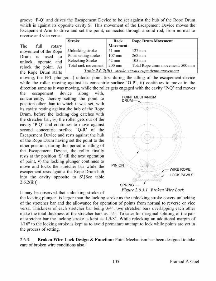
105 Pramod P. Goel
groove ‘P-Q’ and drives the Escapement Device to be set against the hub of the Rope Drum which is against its opposite cavity S'. This movement of the Escapement Device moves the Escapement Arm to drive and set the point, connected through a solid rod, from normal to reverse and vice versa. The full rotary movement of the Rope Drum is used to unlock, operate and relock the point. As the Rope Drum starts moving, the FPL plunger, i) unlocks point first during the idling of the escapement device while the roller moving against its concentric surface ‘O-P’, ii) continues to move in the direction same as it was moving, while the roller gets engaged with the cavity ‘P-Q’ and moves the escapement device along with, concurrently, thereby setting the point to position other than to which it was set, with its cavity resting against the hub of the Rope Drum, before the locking dog catches with the stretcher bar, iv) the roller gets out of the cavity ‘P-Q’ and continues to move against second concentric surface ‘Q-R’ of the Escapement Device and rests against the hub of the Rope Drum having set the point to the other position, during this period of idling of the Escapement Device, the roller finally rests at the position ‘S’ till the next operation of point, v) the locking plunger continues to move and locks the stretcher bar while the escapement rests against the Rope Drum hub into the cavity opposite to S'.[See table 2.6.2(iii)]. It may be observed that unlocking stroke of the locking plunger is larger than the locking stroke as the unlocking stroke covers unlocking of the stretcher bar and the allowance for operation of points from normal to reverse or vice versa. Thickness of each stretcher bar being 3/4", two stretcher bars overlapping each other make the total thickness of the stretcher bars as 1½". To cater for marginal splitting of the pair of stretcher bar the locking stroke is kept as 1-5/8". While relocking an additional margin of 1/16" to the locking stroke is kept as to avoid premature attempt to lock while points are yet in the process of setting. 2.6.3 Broken Wire Lock Design & Function: Point Mechanism has been designed to take care of broken wire conditions also.
Stroke Rack
Movement Rope Drum Movement
Unlocking stroke 51 mm 127 mm
Point setting stroke 107 mm 268 mm
Relocking Stroke 42 mm 105 mm
Total rack movement 200 mm Total Rope drum movement: 500 mm
Table 2.6.2(iii) stroke versus rope drum movement
WIRE ROPE
DRUMPOINT MECHANISM
PINION
SPRING
LOCK PAWLS
Figure 2.6.3.1 Broken Wire Lock
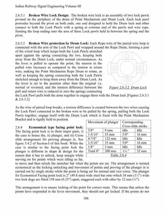
Indian Railway Signal Engineering Volume-III
106
2.6.3.1 Broken Wire Lock Design: The broken wire lock is an assembly of two lock pawls pivoted on the periphery of the drum of Point Mechanism and Drum Lock. Each lock pawl protrudes beyond the pivot on both ends, one end designed to hold the Drum lock and other connect to both the Lock Pawls with a spring at extreme end of the pawls and wire rope, forming the loop ending onto the arm of these Lock pawls held in between the spring and the pivot. 2.6.3.2 Broken Wire protection by Drum Lock: Each Rope wire of the paired wire loop is connected with the arm of the Lock Pawl and wrapped around the Rope Drum, forming a pair of the wired loop which keeps both the Lock Pawls stretched apart against the spring connecting the two, keeping both away from the Drum Lock, under normal circumstances. As the lever is pulled to operate the point, the tension in the pulled wire increases as compared to the tension in return wire, making the Point Mechanism Rope Drum to rotate, as well as keeping the spring connecting both the Lock Pawls stretched enough to keep them away from the Drum Lock. As the lever is set to the position other than the original i.e. normal or reversed, and the tension difference between the pull and return wire is reduced to zero the springs connecting the Lock Pawl pulls both the arms together to engage them with the Drum lock [Figures 2.6.3.1 & 2.6.3.2] As the wire of paired loop breaks, a tension difference is created between the two wires causing the Lock Pawl connected to the broken wire to be pulled by the spring, pulling both the Lock Pawls together, engage itself with the Drum Lock which is fixed with the Point Mechanism Bracket and is rigidly held in position. 2.6.4 Economical type facing point lock:
The facing point lock is in three major parts, i) the case to house the, ii) plunger, and iii) Cross slide arrangement for proving plunger in. See figure 5.4.2 of Section-I of this book. While the case is similar to the facing point lock the plunger is different in shape & design for the reason that it has to unlock, keep margin while moving on for points which were idling so far, to move and then relock the stretcher bar when the points are set. The arrangement is termed economical as the locking unlocking and movement of points and proving of the plunger in is carried out by single stroke while the point is being set for normal and vice-versa. The plunger for Economical Facing point lock is 2" (49.8 mm) wide steel bar onto which 38 mm (1½") wide two lock dogs are fitted 158 mm (6.25") apart, staggered each with other by 12 mm (½"). This arrangement is to ensure locking of the point for correct route. This means that unless the points have responded to the lever movement, they should not get locked. If the points do not
Figure 2.6.3.2 Drum Lock
Movement of plunger Corresponding Cross slide stroke
3/8" 9 mm Idle Idle
1-5/16" 33 mm 5/8" 16 mm
4-7/8" 122 mm Idle Idle
1-5/16" 33 mm 5/8" 16 mm
1/8" 3 mm Idle Idle
Total 8" 200 mm 1¼ " 32 mm
Table 2.6.4

107 Pramod P. Goel
move due to a disconnection in the throw rod, but the plunger moves, the locking dog will recede out of the stretcher bar notches, but the other dog will not be able to enter the other displaced by 12 mm from the alignment of this second dog. Full stroke of the point mechanism cannot be completed under the above circumstances and therefore, when the lever is force latched, it will trip indicating the fault. A cam-path is fitted underside of the plunger to which two roller followers attached to the Cross slide, move along side of the cam-path. The Cross slide gets strokes as tabled numbered as 2.6.4. The lock slide moves along with cross slide connected with. Accordingly the net movement 200 mm (8") of the lock plunger is converted to 32 mm (1¼") of the Lock Slide. See figure 2.6.4 on the next page, for plan and side view of the Facing Point Lock Plunger. Until the Cross slide movement is completed, the rim of the detector shall be obstructed and it shall not be possible to operate the lever to set fully whether the detector is independent or in series of signal wire run. 2.7 Maximum distance up to which the point and signal can be operated: With the 500 mm (20") stroke lever the maximum distance for operation is specified in SEM is 550 yards with transmission length as 1650 feet and pulley spacing as 45 feet. A loss of stroke, which may be due to friction, shall cause a tension difference between the paired wires loop being 186 lbs. In case of point mechanism operation where the stroke on the point switches is to be imparted is 125 mm (4½") only, a minor loss of stroke to points due to some obstruction, which should be able to trip the lever, shall not happen to trip if the clutch is adjusted precisely to 62 lbs. As such for point operation the clutch shall be required to be adjusted at a bit lower than 62 lbs measured on dynamometer. 2.8 Rod Transmission: When transmission for operation of Points, locks, lock bar and holding bar is rod, it is same as detailed in system of single wire signalling section of this book, except for the lever when done from the double wire lever frame is rack & pinion lever.
*****

Indian Railway Signal Engineering Volume-III
108
3/4
"3
/4"
2"
8.2
5"
6.2
5"
Fig
ure
2
.6.4
E
conom
ical
faci
ng P
oin
t lo
ck p
lunger
pla
n &
sid
e vi
ew

109 Pramod P. Goel
CHAPTER- III
SIGNALS & DOUBLE WIRE OPERATED POINTS 3.0 Signals: Structurally major components of semaphore signals are same as discussed in single wire system of signalling, 1st section of this book i.e. i) Signal post, ii) Signal Spectacle, iii) Signal arm and iv) a Signal lamp. While under single wire system of signalling upper quadrant could not be used, it has been possible to provide multiple aspect signalling by using double wire system of signalling, in addition to lower quadrant. Being double wire operated the loop of paired wires terminate at, v) Rope Drum of Signal Mechanism with reference to operation of the signals. As against the system of single wire signalling in which the signal once taken off shall restore to On position by gravity, in case of double wire system of signalling, signal once taken Off shall acquire its On position is not left for gravity but by following a definite movement of the Signal Mechanism Drum, through cam path and crank with roller arrangement, driven through the down rod as a positive act similar to taking the signal Off. 3.1 Signals Lower Quadrant:
Spectacles used for lower quadrant are type ‘A’ and type ‘B’. While the ‘A’ type spectacle, when lowered complete is 500 and type ‘B’ when lowered complete is 450 corresponding strokes being 130 mm and 90 mm respectively. [For spectacles refer Section-I of this Book]. 3.2 Signals Multiple Aspect
Upper Quadrant: [Figure 3.2] Spectacle of upper quadrant signal is designed to display three colour aspects provided with roundels of glass coloured red, yellow and green. A lamp with a clear stepped lens emits a parallel beam through the roundel, seen by the Loco Pilot the coloured light. The arm of the main signal is square ended coloured red with a white band at its tail end similar as in case of signals used in single wire system of signalling [Indian Government General Rules, Rule number 3.08 (3)].
LEVELRAIL
MULTIASPECT
SEMAPHORE
SPECTACLE
PINNACLE
SIGNAL ARM
DOWN ROD
WHITE BAND
DOUBLE WIRE
SIGNAL
MECHANISM
Figure 3.2 Multiple Aspect Semaphore Signal [UQ]

Indian Railway Signal Engineering Volume-III
110
When used as Distant Signal, the arm is fish tailed painted yellow with a fish tailed white band near the tail end of the arm. Another lamp with a lens coloured yellow is fixed 1.5 metres below the lamp used for signal arm, placed on the same post, designed such that the lamp is covered by a metal sheet in 00 (normal) and 900 (Off position) and is exposed to display second yellow light with the signal’s arm is inclined 450 up [Indian Government General Rules, Rule number 3.07 (3)]. 3.3 Signal Post: Tubular as well as lattice signal posts are used to mount spectacles and signal mechanism. The signal mechanism is fixed onto the signal post by ‘U’ clamp holding the base of the signal mechanism in case of tubular post. In case of lattice post Angle iron is fixed onto the lattice post extended to hold the signal mechanism through its base. 3.4 Signal Mechanism: Owing to the double wire system of semaphore signalling the paired wire run forms a loop on the Rope Drum of the double wire lever at one end and on the Rope Drum of Signal Mechanism, onto the independent Rotary Detector or Detector in series of the paired wire run, at other end. Ultimately the rotary movement of the Rope drum of the Signal Mechanism has to be converted into linear movement to provide up and down stroke to the spectacle through down rod connected at one end to the crank of the Signal Mechanism and to the spectacle onto the signal spectacle on the other end. The linear movement of the down rod again gets converted into rotary movement of the spectacle rotating about the hub. For converting the rotary movement of the signal mechanism drum, into linear movement of the down rod, a mix of concentric and eccentric cam path is designed into which a follower roller moves having been fitted at the end of the one arm of the crank, the other arm of which is connected to the down rod at one of the holes in the arm, to adjust amount of throw to the down rod. The Signal Mechanism Drum is mounted on a bracket and is provided with the cover against outside interference. The Crank is pivoted onto its hub pin fixed on the Bracket of Signal Mechanism. The assembly consisting of the drum and the bracket along with the crank constitutes the Signal Mechanism. The Bracket is mounted on the tubular or lattice signal post as the case may be. The cam path of the drum is designed not only to provide linear movement to the down rod but also to cater for extra rotary movement for stabilizing the signal including wire breakage conditions due to over run. It is the eccentric pathway which provides stroke to the down rod transmitted by the crank while the concentric path way is to take care of i) variation in loss of stroke in transmission, ii) variation in uncompensated length of transmission wire between coupled signals, iii) minor maladjustments in the transmission and iv) to cater for outside interference to keep the signal stabilized after having been taken Off or to throw the signal On, under wire breakage conditions. Accordingly the stroke imparted by the lever can be put in sections, i) initial idle stroke of 137 mm, allowance to cover-up variation in the loss of stroke while putting lever from reverse to normal, to stabilise the On aspect, ii) the working stroke 250 mm for operating the signal and iii) final idle stroke of 113 mm to stabilise the Off aspect to cover up variations due to loss in

111 Pramod P. Goel
stroke when the lever is operated from normal to reverse. Accordingly the net stroke imparted by 500 mm (20"), gets distributed as detailed above. Signal Mechanism is said to be left hand when the crank arm connected to the signal, Down Rod is placed left hand with reference to the centre of the signal mechanism when viewed by the observer facing the mechanism and vice-versa for right hand. The left hand or
right hand signal mechanism can be fixed onto the signal post by making suitable alterations to the mechanism. A pendulum is provided concentric to the hub of the signal mechanism drum with Stop fixed onto the bracket to limit the movement of the drum. This arrangement is called as Signal
Mechanism Drum Lock and is used to i) arrest the motion of the Signal Mechanism drum as soon as the signal assumes On, ii) limit broken wire stroke at the compensator, and iii) make the signal aspect immune to the rotation of the drum due to inertia in case of wire breakage. The push-pull coupled signal mechanism shall have only one stop as the signal mechanism drum is likely to rotate in any direction while the signal mechanism drum for single (uncoupled) lever shall have two stops to prevent its rotation other than to normal. Signal Mechanism is nominated with respect to the position of the signal which could be attained by using the said signal mechanism. For example 450-0-900 signal mechanism shall cause the signal to acquire 450 inclined upwards to horizontal when the Signal mechanism drum rotates clockwise with reference to its neutral position i.e. when the signal arm is horizontal. However when the Signal mechanism drum is made to rotate anticlockwise from its neutral position the signal arm shall acquire 900 above horizontal. Accordingly this arrangement is termed as Left hand 450-0-900 Signal Mechanism. 3.4.1 Signal Mechanism for Pull-Pull arrangement of Lower Quadrant: 3.7/16" stroke is imparted to the down rod of lower quadrant ‘B’ type signal. Lower Quadrant, Double Wire, Pull-Pull coupled Signal mechanism is used for two lower quadrant signals on one and the same post. It may be observed that as the lever-1 is to take the outer signal Off, the Warner may be taken off by pulling second lever in succession. As may be seen in figure 3.4.1, while crank
PENDULUM
CRANK-1CRANK-2
DRUMBRACKET
Figure 3.4.1 L.Q. (DW) Pull-Pull coupled
Signal mechanism
BRACKET
CRANK
8.5
" S
TR
OK
E
DRUMROLLER
ROLLERPATHWAY
PENDULUM
Figure 3.4.2 (U.Q.) D.W. Signal Mechanism
450-0-90
0

Indian Railway Signal Engineering Volume-III
112
-1 shall lift the down rod the Outer signal number-1 shall be taken Off without affecting any movement to crank-2, its pathway being concentric. As and when lever number-2 is pulled, the crank-1 shall remain affected following concentric path while the crank-2 shall follow the eccentric path to lift the down rod of the Warner signal. 3.4.2 Signal Mechanism 45
0-0-90
0 for Upper Quadrant, Push-Pull arrangement: Upper Quadrant, Double Wire signal to Push-Pull coupled 450-0-900 Signal Mechanism [Figure 3.4.2] is to take the signal Off for 450 by lever-1 rotating the signal mechanism drum in clockwise direction and with this lever normal, operation of lever-2 rotates the signal mechanism drum in anticlockwise direction putting the signal to 900 directly. This Signal Mechanism works a three aspect Starter Signal and also used to work a Distant Signal, shown in the figure is for right hand Signal Mechanism. 216 mm (8 ½") stroke is imparted to the down rod to raise the signal arm to 900 upwards. Stroke imparted on the down rod shall be different for Type ‘A’ and type ‘B’ spectacles and also for different strokes downwards or for 450 & 900 upwards. 3.4.3 Signal Mechanism for Upper Quadrant,
single transmission for 0-450 position: This
mechanism is used for single transmission required to work one signal only, for its 450 position, such as loop line Home Signal, loop line starter signal and shunt signal. The stroke imparted to the down rod is 108 mm. [See figure 3.4.3]. 3.4.3.1 Signal Mechanism for Upper Quadrant,
Push-Pull arrangement 0-0-450: In this case same
signal Mechanism is used as that used for 0-450 arrangement, for two signals on different signal posts for operation of one or both push-pull coupled signals. The signal Mechanism is same for both arrangements of 0-450 and 0-0-450 except for the signal mechanism of 0-450 arrangement shall have two stops, while for arrangement 0-0-450 it shall have one, the normal stop. See the figure 3.4.3.1 for Upper Quadrant, Push-Pull Mechanism, 0-450 or 0-0-450 the trajectory followed by the roller of the crank is shown dotted. 3.4.4 Signal Mechanism for Upper Quadrant Pull-Pull arrangement 0-45
0-90
0: See the
figure 3.4.4, as the lever-1 is pulled the signal mechanism drum rotates clockwise causing the crank to raise the down rod as the roller moves into the pathway to take the signal Off to 450. With the pulling of lever-2 the crank arm causes the rise of down rod further to take the signal Off to 900.
DRUM
BRACKET
PENDULUM
CRANK
Figure 3.4.3 & 3.4.3.1 (U.Q.) D.W.
Signal Mechanism 0-450 or 0-0-45
0

113 Pramod P. Goel
3.4.5 Other Signal Mechanisms for Upper Quadrant: Other Signal Mechanisms with different requirements are discussed in ensuing paragraphs. 3.4.5.1 Signal Mechanism with Pull-Pull
arrangement 0-900: This Mechanism is used for
operation of single signal to take the signal Off to 900 only such as main line starters or Last Stop Signal (LSS) such as Starter and Advance starter. The stroke imparted to the down rod is 216 mm. 3.4.5.2 Signal Mechanism with Push-Pull
arrangement 0-0-900: The Signal Mechanism is
used to operate main line starter to the 900 position when coupled Push- Pull with another signal on a separate post. The only difference between 0 - 900 and 0- 0-900 signal mechanism is that the first one has two stops and the second one only one. 3.4.5.3 Signal Mechanism with Push-Pull
arrangement 450-0- 45
0: As and when one signal
leads to two different routes, it is operated by either of the two different levers to take it Off to 450 for the sake of interlocking arrangements. 3.4.5.4 Signal Mechanism with Push-Pull arrangement 90
0-0- 90
0: Similar to the 450-0-
450 Mechanism, operated by two different levers, this arrangement is used for one signal leading on two different routes, except for the high speed turnouts which allow higher speed over the turnouts permitting the signal to be taken Off to 900. 3.4.5.5 Signal Mechanism with Pull-Pull arrangement: 0-450-900 Signal Mechanism:
Used for working three aspects signals such as Main Line Home or Distant Signals 0-450-900 is
a pull-pull signal mechanism. Under this arrangement one signal lever is pulled to impart 450 position and then operated by the other signal to impart 900 position. 3.4.6 Signal Mechanism with Push-Pull Upper Quadrant using Double Cranks: The Signal Mechanism is used for two conflicting upper quadrant signals on the same post. It has 450 aspect only using Push-Pull coupling arrangement. The down rod imparts 108 mm stroke.
*****
BRACKET
PENDULUM
ROLLERPATHWAY
CRANK
DRUM
Figure 3.4.4 (U.Q.) D.W. Signal
Mechanism 00-45
0-90
0

Indian Railway Signal Engineering Volume-III
114
CHAPTER- IV
MONITORING, LOCKING & SAFETY DEVICES 4.0 Wire breakage, associated conditions and broken wire protection: As against single wire system of operation, the double wire system of operation covers operation of signals, points, facing point locks and detectors. Accordingly both the paired wires under double wire system of operation are kept under tension by double wire compensators. This in turn if causes breakage of any one of the paired wire to create unsafe conditions due to the compensator weight start falling out of gravitational force, to the extent of broken wire stroke available on the ratchet rod (of the compensator), pulling both wires. This may operate point, signal or the detector, creating unsafe conditions when a train movement is scheduled to or taking place. Measures taken to safeguard such unsafe conditions are i) tripping of clutch levers, ii) Broken wire stroke provided on the ratchet rod of the compensator and iii) over run pathway provided on the Signal Mechanism drums and signal mechanism drum-Lock. 4.1 Affects of tripping of Lever Rope Drum of the Clutch Lever: As the tension difference is created due to an obstruction in the transmission or breakage of any one of the paired wire loop, the lever shall trip, as and when the tension difference rises by 85 kg or beyond, adequate enough to trip the lever Rope drum. Since tripping of the lever rope drum is safety sensitive, the adjustment for allowing tripping shall be kept critically 85 kg or below but not lesser than 72 kg. This tripping of the Lever Rope Drum, i) shall impart 12 mm movement to the locking plunger (Tappet) in the direction last operated and, ii) shall also cause 75 mm (3") rotation of the lever rope drum. This movement of the lever rope drum shall impart 75 mm movement to the mechanism drum due to tripping. However if two coupled levers trip together the mechanism drum shall rotate by half which is 37.5 mm. This rotation of drum may be forward or backward depending upon position of wire breakage. Affect of tripping on mechanism drum under situations and different point of breakage shall be
discussed in ensuing paragraphs. 4.1.1 Affect of tripping of Lever Rope Drum on interlocking: Tripping of Lever Rope Drum shall impart 12 mm motion to the locking plunger (Tappet) activating interlocking. It shall depend upon the design of Locking Table (Dog-Chart) whether the locking provided is loose or tight. In case of locking being loose, it shall not cause any affect on the interlocking due to tripping but in case of locking being tight the tripped of the lever shall cause the affected lever to be locked in last operated position. 4.1.2 Affect of tripping of Lever Rope Drum resulting in its movement forward or
backward: The Lever Rope Drum rotates due to uneven tension between the paired wires of the loop due to its tripping. This rotary movement of the Lever Rope Drum may be forward or

115 Pramod P. Goel
backwards depending upon the position of breakage in the wire creating uneven tension between the two paired wires of the loop. 4.1.2.1 Forward and backward movement of the wire with the tripping of Rope Drum:
Considering that, under the coupling arrangement, the return rope wire connected to the coupling device lever, breaks the coupling device lever shall fall almost vertical while the Rope wire on pull side of the lever drum, which is intact and firmly wrapped upon the Lever Rope Drum shall cause the wire to be pulled by the falling weights of the compensator, making the Lever Rope Drum to rotate in the direction which is opposite to the direction when the lever is pulled to be set on reversed position. This implies that the movement of the wire rope due to this tripping is “backwards” and vice-versa. This shall also be read as imparted stroke by the lever due to tripping. 4.2 Affect of wire breakage on equipment operated: As a wire out of the paired wire loop breaks a tension difference is created between the pair of wire loop one wire being free and other under tension. The Compensator lever wheel starts rising due to weight trying to fall down under condition of no or negligible tension on the wire broken. Since both the levers of the compensator are coupled the compensator lever which is free of tension shall take along with it the intact wire also. The intact wire while being pulled shall cause to, i) impart tension on the associated clutch lever drum to cause it to trip if the force is enough to trip the lever rope drum on one end and, ii) rotate the Mechanism Drum of the signal, point or detector under associated conditions. The pull on the intact wire shall be limited by Signal Mechanism Drum Lock, Detector’s Control Rim or the point machine lock as the case may be. There may be conditions under which the detector may rotate unrestricted when detecting normal set point. The details may be seen in ensuing paragraphs. This rotation of the Mechanism drum of signal, point or detector under associated conditions, may create unsafe conditions to be investigated under the Broken Wire Protection subject. 4.3 Movement in case wire breakage under coupling arrangement: As a coupled lever is pulled it locks the associated coupled clutch lever, during operation, to prevent the initial wire tension imbalance causing the other lever to trip as the lever which is being pulled can not trip while it is on the Quadrant and by the time the lever is put to rest on either position the tension difference between the paired wire loop becomes settled and as such normal, below the tension range of tripping. There may be combinations of direct lever and clutch lever; and clutch lever & clutch lever. Only the direct lever shall lock the clutch lever in, direct to clutch lever combination and either of the paired clutch lever shall lock the other under clutch lever–clutch lever combination. As one of the paired wire of the loop breaks, it causes i) falling of the Coupling Device Lever, and ii) rising of the compensator lever wheel both resulting in pulling of both ends of the compensator lever wheel, the intact wire. This shall cause pull of the wire, double the rise of the compensator lever wheel.

Indian Railway Signal Engineering Volume-III
116
The Coupling Device Lever is 500 mm long with its one end hinged on a support. The wheel on the coupling device lever is placed at half the length of the Coupling device lever, on a pivot 250 mm from the hinge. As the wire breaks, the wheel shall fall by 125 mm as the coupling device lever shall fall about its hinge almost to vertical. In case the lever is pulled the drop of the Coupling Device Lever wheel shall be 375 mm (15"). 4.4 Postulates of interlocking, under broken wire conditions: Under the postulates of
interlocking, under broken wire conditions, i) Signal with the lever normal- The signal shall continue to be On; with lever reversed the signal shall continue to be Off , may acquire less restrictive aspect or preferably go to On; ii) Points- set to either way should remain in last operated position or if at all have to move they shall set completely to either position keeping no gap between switch rail & stock rail; iii) Detectors- A detector is functional only when its lever is reversed otherwise it has no role to play, as such when detector lever is reversed, it should continue to hold the points in last operated position, iv) Clutch lever- Lever Drum must trip to foul the interlocking if locking is tight. 4.5 Broken wire protection for signals and Detectors: Broken wire protection for, A) Signal when- i) lever normal, ii) lever reversed, iii) Push –Pull coupling, iv) Pull-Pull coupling, v) signal wire run without Detector in series and, vi) signal wire run with Detector in series; B) Point, C) Detector, D) Clutch lever and E) coupling arrangements, shall be to comply with the postulates of interlocking, under broken wire conditions as discussed in preceding paragraph. 4.5.1 Broken wire protection for signal: When movement of the Signal mechanism drum takes place in the direction same as that of taking the signal Off, the broken wire stroke on Double Wire Compensator is used as Overrun Stroke on Signal Mechanism. The Over Run Stroke is kept larger than the lever stroke used to stabilise the signal in Off position and is meant to replace the signal to On. The broken wire stroke is kept larger than compensation stroke on the double Wire Compensator, which provides Overrun stroke to the Signal Mechanism drum, while rotating. 4.5.1.1 Broken wire protection for single signal & no detector in wire run for the given
signal: Broken wire protection for signal when lever normal: When the wire breaks between lever and the compensator- As the return wire breaks, the weight on the Compensator Lever shall fall, having been left with no tension in the wire, concurrently lifting the wheel on the other end of the Lever to the extent of Wire Breakage Stroke. Suppose the wheel falls by 150 mm it shall create a gap of 300 mm in between both ends of the wire broken. Both Compensator Levers falling together, the other Compensator Lever with intact wire (Pull wire) shall also be pulled by 300 mm, causing i) the drum of the signal mechanism to rotate by same amount as well as, ii) result in increasing the gap between broken ends of the wire by 600 mm doubling the gap. This establishes the rule that the movement of the rope drum of the Mechanism is half the gap
between broken ends of the wire.
117 Pramod P. Goel
As the Pull wire breaks between the Lever and the Compensator, the return wire shall get pulled to rotate the signal drum of the Mechanism in the direction opposite for taking the signal Off getting locked in position after covering the initial idle stroke without affecting the signal aspect. Accordingly applying the same principle on coupled levers, a break in one of the coupling loops between lever and the compensator, in case of Push-Pull coupling arrangement the drop of the coupling wheel shall be 125 mm causing the gap between broken wire ends as 250 mm, causing movement of the signal mechanism by 125 mm which is equal to the drop of the wheel.
4.5.2 Broken wire protection for Rotary Detector: The role of rotary Detector comes in only when the lever of Detector or Signal with Detector in series, is reversed. There could be conditions i) Detector operated by an independent lever, ii) Detector is wired in series with a signal and iii) Detector and signals are operated under coupling arrangement. 4.5.2.1 Detector operated by an independent lever; pull wire Broken: Detector’s Detection Rim is extended up to Control Rim to cater for rotation of the detector drum when the last pulled wire (pull wire) is broken. If the pull wire is broken with lever in reversed position, the detector wheel shall rotate in the direction same which caused the lever operation from normal to reverse, which in turn shall cause the detector to keep the detector slides held in last operated position of points by the Detecting Rim or extended to the Control Rim as the case may be. 4.5.2.2 Detector operated by an independent lever; return wire Broken: In case of breaking of return wire, the detector drum rotates in direction opposite to the lever being pulled as if the lever was being put back to normal from reversed position. However, in this case, the Detector moves further to hold the points engaged by the locking rim. 4.5.3 Broken wire protection for signals under coupling arrangement, without
detectors: Two levers operate either of the two signals placed on the same post by one and the same Signal mechanism. Since it is push-pull arrangement the paired wires of the loop work as pull-1 and pull-2. 4.5.3.1 Break in coupling loops: There may be conditions under which both Signal levers are normal, Signal-1 lever reversed or Signal lever-2 reversed. i) Condition under which both Signal levers are normal: With breakage of any of the two pull-1 or pull-2 wires the Coupling Device Lever Wheel shall drop down by 125 mm being almost vertical about the fulcrum causing the Rope drum of Signal Mechanism to move backward by 125 mm, sufficient to take the signal-2 Off, consequently resulting in the compensator wheel to rise by 62.5 mm (half of fall of Coupling Lever). If the lever-1is free to trip, the tripping of the Rope Drum shall result in drum to rotate forward by 37.5 mm with the net movement of the Signal Mechanism being backward by 87.5 mm (125-37.5 mm). The over run cam-path shall cause the Signal back to On.

Indian Railway Signal Engineering Volume-III
118
ii) Condition under which Signal lever-1is reversed: With breakage of wire of coupling loop of lever-1 Signal Mechanism shall move backwards as if being set to normal position simultaneously dropping down of the Coupling Devise Lever wheel by 375 mm, from its original lifted position of 250 mm above the fulcrum, causing in turn the Signal Mechanism to put the signal back to On moving by 375 mm to normal position of the lever. The compensator lever wheel shall rise by 187.5 mm. If the Rope Drum of lever-1 trips, it shall result in 37.5 mm movement of the rope drum in direction opposite to the one caused due to the wire breakage resulting in Signal Mechanism to move 337.5 (375-37.5) mm, signal to cause to droop due to reduction in over all movement of the Signal Mechanism. Lever-2 cannot trip having been drum locked due to lever-1, being reversed. iii) Condition under which Signal lever-2 is reversed: Similar conditions shall prevail when the lever-2 is reversed when the wire breaks. 4.5.3.2 Break in wire transmission: There may be conditions under which both Signal levers are normal, Signal-1 lever reversed or Signal lever-2 reversed. i) Conditions under which Both Signal levers are normal: Due to break in wire of
coupling loop of lever-1, the Compensator Lever wheel shall rise by 387.5 mm (15½") causing the return wire to be pulled by 775 mm (31") and signal drum being stopped by the signal mechanism lock and double the rise of the compensator lever wheel. This shall cause the signal-2 to go to Off position momentarily coming back to On. Similar shall be action in case of breaking of wire pull -2. ii) Signal Lever-1 is reversed: Due to break in wire of coupling loop of lever-1, two situations may arise, the return wire shall pull i) 775 mm (31") signal drum being stopped by the signal mechanism lock, or ii) 775+500 mm=1275 mm (31"+20"=51") signal drum being stopped by the signal mechanism lock in opposite direction. In condition (i) the signal number -2 shall go to Off aspect momentarily and return to normal and condition (ii) Signal number-1 shall go to On and signal number-2 shall go to Off momentarily and then to On. iii) Signal Lever-2 is reversed: Similar action shall take place when pull-2 wire is broken. In both the cases the lever if free shall trip which in-turn shall cause the Compensator Lever Wheel to rise and accommodated by the compensator wheel without affecting the Rope drum of the Signal mechanism. iv) Signal Lever-1 is reversed: Due to break in wire of coupling loop of lever-2,
signal Mechanism Rope Drum shall rotate by 125 mm in over run direction due to Coupling

119 Pramod P. Goel
Device Lever of lever-2 dropping by 125 mm and compensator wheel rising by 62.5 mm (half of the fall of coupling loop lever by 125 mm). Due to idle over-run being only 110 mm the drum shall cause the signal to droop short of being to On. To avoid this, the lever-1 shall be put back to normal due to which lever-2, which was locked when the lever-1 was being reversed, shall also trip resulting in reverse movement of the Signal Mechanism Drum by 37.5 mm putting the signal back to On. 4.5.4 Broken wire protection for signal with detectors in series: There are two arrangements, one being in which Detector is operated by an independent lever and the signal lever is pulled there after back-locking the detector lever. In other method the Detector is put in series with the paired wire loop to operate signal while concurrently detecting the associated point. The operation of independent signal and independent detector has been discussed in preceding paragraphs; the Detector in series with the signal is discussed herewith as follows. 4.5.4.1 Wire break in coupling loop, both Signal levers normal, points normal and
detector in series with signal transmission: i) Broken wire protection due to break in wire of coupling loop of Signal lever-1: The Detector shall be restricted to move more than 100 mm restricting the signal mechanism drum also to rotate through initial idle cam path of signal-2, of the signal mechanism drum, by 100 mm. The compensator wheel shall also be restricted to rise by 50 mm only. This shall keep both the signals at On. Tripping of the lever shall cause the compensator wheel to rise to 87.5 mm reversing the rotation of the signal mechanism drum, resulting in return of transmission wire due to tripping, by 37.5 mm, without change in status. Similar shall be the condition if points are reversed and coupling loop of lever-2 breaks. ii) Broken wire protection due to break in wire of coupling loop of Signal lever-2:
With the break of wire in coupling loop-2, the Detector shall be free to rotate unrestricted, when points are set to normal, controlled by signal mechanism lock. This shall not affect the signals being kept at On. 4.5.4.2 Break in transmission paired wire loop between lever and detector: Two signals on the same post under Push-Pull arrangement operated by one and the same signal mechanism. i) Points normal and both Signal levers normal: With the break in pull-1 wire, the compensator wheel shall rise by 50 mm (2") due to paired loop pull wire-2 causing the rotation of the detector being restricted by 100 mm (4") by the Control Rim (high rib) of normal detector, locking the point and rotating the Signal Mechanism Drum backwards by 100 mm (4"). However this shall not affect maintaining the signal position at On. Similar condition shall prevail when point is reversed and pull-2 wire is broken.
Indian Railway Signal Engineering Volume-III
120
ii) Points normal and both Signal levers normal: With the break in pull-2 wire, the compensator wheel shall rise by 387 mm (15½") due to paired loop pull wire-1 causing the Detector to rotate unrestricted, locking the point and rotating the Signal mechanism drum forward by 775 mm (31") on getting stopped by the signal mechanism lock. This shall not affect maintaining the signal position at On. Similar condition shall prevail when point is reversed and pull-1 wire is broken. iii) Points normal and Signal lever-1 reversed: With the break in wire pull-1, the compensator wheel shall rise by 300 mm (12"), causing the paired wire pull-2 to pull the wire and rotate the Signal Mechanism Drum backwards simultaneously rotating the Detector by 600 mm (24") restricted by the normal detector Control Rim (high rim). This shall cause the point to be locked by both detectors and putting the signal-1 back to On. Similar conditions shall prevail when point is reversed and lever -2 is reversed pull-2 wire is broken. iv) Points normal and Signal lever-1 reversed: With the break in wire pull-2, the Compensator Lever wheel shall rise by 137.5 mm (5½"), causing the paired wire pull-1 to pull the wire and rotate the Signal Mechanism drum forward by 275 mm (11"), held by Signal Mechanism Lock allowing the Detector Rope Drum to rotate unrestricted. The points are kept locked by normal detection rim & signal-2 going back to On. Similar conditions shall prevail when point is reversed and lever-2 is reversed and pull-1 wire is broken. 4.5.4.3 Break in transmission of paired wire loop between Detector and Signal: Two signals on the same post under Push-Pull arrangement, operated by common signal mechanism. i) Points normal and both signal levers normal: With the break in pull-1 wire, the compensator wheel shall rise by 387.5 mm (15½") due to break in paired loop pull wire-2, causing the rotation of the normal detector rim freely beyond 775 mm (31") (double the rise of compensator wheel) being ultimately restricted by the Control Rim (high rib) of normal detection wheel, locking the point and rotating the Signal Mechanism drum backwards by 775 mm (31") getting held by the Signal Mechanism Stop. This shall cause the signal-2 to go to Off momentarily and then back to On. Similar conditions shall prevail if the points are reversed and pull-2 wire breaks between detector and the signal. 4.5.4.4 Break in transmission paired wire loop when Signals are placed on separate
posts under Push-Pull arrangement: When two different signals are placed on different posts such as starters from different lines any one of the two shall be taken off at any one time. In this case two independent Signal Mechanisms shall be provided for each of the two signals. This

121 Pramod P. Goel
shall also necessitate use of two independent detectors provided in pull wire-1 and pull wire -2 of the paired loop. In this case all conditions of wire breakage under Push-Pull arrangement on two signals on the same post shall apply too even though two separate Signal Mechanisms are used. However the condition under which wire breaks between two signals are discussed as follows: i) Points normal and both Signal levers normal: As the wire between the two signals breaks the compensator wheel rises by 387.5 mm (13½") pulling both wires, making the Signal Mechanism Drums of both signals to rotate. As the signal-1 mechanism drum rotates forward, the signal-2 mechanism drum rotates backwards. This shall take the signal-1& signal-2 to Off momentarily and then to On as the both signal drums shall rest with the mechanism drum lock due to pull of wire by 775 mm (31") (double of the rise of compensator wheel). Similar conditions shall prevail if the points are reversed when the wire breaks. ii) Points normal and Signal-1 lever reversed: As the wire pull-1between the two signals breaks the compensator wheel rises by 137.5 mm (5 ½") pulling wires on both ends of the wheel, making the Signal Mechanism Drums of both signals to rotate. Wire Pull-1 shall rotate forward by 275 mm (11") restricted by Signal Mechanism Stop, causing the Sigal-1 to go to On while simultaneously the detector shall hold the point locked by its normal detection rim. Pull-2 wire shall be pulled back by momentum up to 127 mm (5") maintaining signal-2 to its On position. However the system can not be relied on chance and there is every likely hood of signal-2 going Off, resulting the Loco Pilot to lead the train onto the sand-hump. Similar conditions shall prevail if the points are reversed when the wire breaks creating further more difficult situation. 4.5.4.5 Signals provided with reversers: As and when signals are provided with reversers, there shall be no adverse affect on the signal with breakage of wire till the signal is not taken Off, and the reverser is not energised. 4.6 Broken wire protection for Point: The broken wire protection against Double Wire Point Mechanism is taken care by, i) Drum-Lock and , ii) Double Wire Rotary Detector, when operated. 4.6.1 Broken wire protection for Point by Drum Lock: Details of design and its function of broken wire protection for Point with Drum Lock may be seen at preceding paragraph 2.6.3, however broken wire protection by Double Wire Rotary Detector is detailed as follows. 4.6.1.1 Broken wire protection for Point by Rotary Detector: When the Detection is operated, the associated point is held in last operated position by the Detector Locking Rim. In case the detector is not operated, the point may be held in the last operated position by the Lever Locks engaged with the Lock Drum or if not engaged, it may move full round due to tension difference between paired wire loop till the tension difference is reduced so much so

Indian Railway Signal Engineering Volume-III
122
that Drum Lock Springs get pulled together to engage with the Drum Lock and hold points in position other than to which it was originally set before wire breakage. However the arrangement is not found to be very reliable and the facility of holding the point through detector slides by the rotary detector is used as supplement. 4.7 Layout Facing
Point Lock, Economical
Facing Point Lock & Lock
bar under double wire system of signalling: [Figure 4.8] A mechanical Facing Point Lock (FPL) operated by an independent lever, provided to hold the points in last operated position till the plunger is pulled out of the split stretcher bar of the points, is discussed in Section-1 (Single wire system of Mechanical Signalling) of this book. The plunger of the FPL is pushed inside or pulled out of the case of the lock, by rod running between the lever and the FPL plunger. 4.7.1 Economical Facing
Point Lock under double
wire system of signalling: Under the Double wire system of mechanical signalling, the point is not only locked but also is operated by the a rotary Point Mechanism by converting the rotary movement of the Point Mechanism Rope Drum to linear movement as discussed in preceding paragraphs of this section.
RA
CK
PO
INT
ME
CH
AN
ISM
LOCK BAR
LEADING
STRETCHER BAR
AD
JU
ST
AB
LE
CR
AN
K
HORIZONTAL CRANK
Fig
ure
4.7
P
oin
t la
yout
of
poin
t oper
ate
d b
y D
ouble
Wir
e poin
t M
echanis
m E
FP
L w
ith
lo
ck b
ar

123 Pramod P. Goel
As rack of the Point Mechanism moves back and forth it unlocks the points, pauses to allow the point to move and set it to the opposite side and relocks the point in last set position. To accommodate the requirements, as discussed, the lock plunger is designed accordingly. Since the entire set of operations including the lock is executed by one set of lever and paired loop of wires the FPL used for double wire is termed as Economical Facing Point Lock (EFPL). While the train traverses the station section, holding the route is another special feature of signalling system, which is achieved by providing Lock Bar and Holding Bars. 4.7.2 Lock-bar, under double wire system of signalling: The Lock Bar associated with EFPL is used to prevent movement of the lock plunger under the wheels of a train passing over or standing on the points. Accordingly the Rack of the Point mechanism gives drive to the associated Lock Bar, which in turn is connected to the plunger of the EFPL. It is pertinent to note here that the total drive of the Rack of the Point Mechanism is kept 8" (200 mm), to fit in operation of the Lock Bar back and forth and concurrently operation of the EFPL plunger. For EFPL plunger movement details refer table 2.6.4 in preceding paragraphs. As and when the distance between the Signal Post and the first point on the train’s route is more than 180 Metres, another independent Lock Bar termed as ‘Holding Bar’ shall be provided in between the lock bar associated to the point and the signal post, operated by another lever, back locked by the facing point lever enroute. This restriction of distance of 180 Meters shall be maintained for the given route up-till the destination, having cleared the last point in the route. 4.7.3 Economical facing point Lock and Lock bar: Out of Essentials of Interlocking as provided by the Signal Engineering Manual (SEM), i) Points falling in direction facing the train, are required to be held in position without allowing any gap (within reasonable limits) between the switch and stock rail and ii) it shall not be possible to change the setting of the point under the wheels of a train running or standing on the points. 4.8 Holding the route: The route is held by means of Holding bars provided in between the signal concerned and the first point to be encountered by the train. Such Holding bars are operated by Rack & Pinion Levers. The Rod run is provided in the manner same as for Single Wire System of Signalling to hold the route. For details refer to system of single wire signalling in Section-I of this book. A heterogeneous mix is also used by operating the point by the Double Wire Point Mechanism with the Economical Facing Point lock or by operating point through Double Wire Point Mechanism with an independent Facing Point Lock, operated by the Rack & Pinion Lever or both, the Point and Facing Point lock may be operated by Rack & Pinion Lever.
*****

Indian Railway Signal Engineering Volume-III
124
Bibliography
1. Indian Government Railways General Rules. 2. Compendium on Instructions on matters pertaining to condonation of infringements
to schedule of dimensions, CRS & Railway Opening of Public Carriage of Passenger Rules, 2000, issued by CORE.
3. Signal Engineering Manual Part-I, 1988. 4. Notes issued by IRISET on S3 & S4. 5. Indian Railway Administration and Finance an introduction. 6. Objective Railway Engineering by M.M. Agarwal. 7. E.I. Interface wiring diagrams of station Rundhi. 8. Electric lever frame courtesy Westinghouse Brake & Signal Co. Ltd.
*****
References
1Indian Railway Signal Engineering Volume-I 3Indian Railway Signal Engineering Volume-III 4Indian Railway Signal Engineering Volume-IV, for details.
*****

i
INDEX
Indian Railway Signal Engineering Volume – II
25 KV AC traction 29,86
Absolute Block System 2,36
AC track circuits 31
Address circuits 112
Address select PCBs 113
Advantages of Axle counters 32
Allocation of the cables 88
Analogue axle counters 98
Anti Collision Devices 34
Apparatus case 84 Apparatus Case wiring diagram 99
Approach Locking 27,28
Audio Frequency TC (AFTC) 32
Automatic Block Signalling 37
Automatic Block System 2 Automatic Warning System (AWS) 34
Back Locking 27,28
Bit Chart 107,108
Block overlap 10
Block section 6,7
Block working 36
Boolean equations 106
Cable Core Allocation Plan 86,89
Cable Core Insulation Chart 121 Cable Core Termination Chart 89,90
Cable Route Plan 83,85
Cable Termination 91
Cable Termination Rack 90,92
Calling-On Signal 43 Card file keying plug locations 110
Card file layout 110 Catch Handle type of Interlocking 81
Catch Siding 47
Central operation 42 Circuits for different power supplies 118
Classification of station 5 Clear Available Length (CAL) 29
Clear Standing Room (CSR) 3
Clearance Bar 27,28
Colour Light Signals 59 Commercial & political factors 9 Commissioner of Railway Safety (CRS) 50,51
Communication 48
Composite Rack 92 Conditional or Special Locking 70
Conditions for granting Line 5,6
Conflicting signals 69
Contact analysis 103,119
Control cum indication panel 23,27
Counters 26
CPU 113
CPU board jumper settings 115
CPU Clock Supply circuits 117
Crank Handle 48
CRS’s sanction 50
Data logger 33,117
DC track circuit 31
DC traction 28
Deciding location of cabin 41 Diagnostic Serial Communication circuits 116
Diesel Engines 28,29
Digital Axle counters 98
Direct locking type 16,80

ii
Direction of traffic 6
Directly opposite signals 70 Disadvantages of Axle counters
32
Double line section 36
Double wire compensators 20
double wire lever frame 78 Double Wire operated equipments 64
Double wire signalling 39
Double wire system 19 Double wire system of operating 40
Earth Leakage Detector 121
Economy 69
EEPROM 113
Effect of traction 28,29
Electric traction 28,29
Electrical interlocking 21,40
Electrical signalling 26
Electrification 52
Electronic Interlocking 26,40,106
Engineering Scale Plan (ESP) 3,56
Equipment Disposition Plan 121,122
Essentials of Interlocking 12
Features of the section 9
Filling the square sheet 74
Flank Protection 28
Foot by foot survey 86
Fouling Bar 27
Fuse 90,94 Geographical system of numbering 62,63
Goods Wharf 47
Goomty 41
Gradients 12
Granting of Line clear 11
Ground lever frame 21
GSM-Railway 48
Horizontal cancellation 73,75
Hot axle siding 12
Housing relays 84
I/O Jumper settings 112
Importance of the section 9
Indications 24 Integrated Power Supply (IPS) 38,124
Interface Circuits 107
Interlocking by double wire 21
Interlocking Chart 80 Interlocking Chart for Double wire 81
Interlocking Circuits 104
interlocking relationship 72
Interlocking Table 68,76
Interlocking Wiring Diagram 101
Intermediate Block Signalling 2,11
Intermediate Block System 37
Junction box 84 Keying arrangements for card files 110
Last vehicle check 41
Legal authorisation 50
Level crossing gate 44,45,48
Lever 19
Lever Frame 16,19,42,60
Lever-Lock 17
Lock Bar 27
Locking both ways in 68
Locking one way in 68
Locking Plungers (Tappet) 16,17,21
Logic Circuits 106
Long Siding 47
Loose locking 79 Main Distribution Frame (MDF) 90 Maintenance PC Communication circuits 117,118
Master-Slave 116
Mechanical Interlocking 21

iii
Micro Circuit Breakers (MCB) 94
Minimum depth of the trench 86
Mobile communication 48 Mobile Train Radio Comm. (MTRC) 48
Monitoring running train 41
Monitoring track vacancy 31,33 Multi Section Digital Axle Counters 98
Multiple aspect signalling 10
Nokia Siemens Networks 48
Non-route setting 23
Numbering on the SIP 60
Opening of works 50
Operated Equipment 30,42
Operating Device 19,30 Operation of colour light signals 40 Operation of level crossing gates 45
Operation of point 20,30
Operation of Signal 20,30
Operation of the Lever 78
Overlap considerations 10
Panel Diagram 66
Permissible speed 4
Placement of Terminals 92
Plans & drawings 50,55
Points 44,59
Power frame 21
Power operated lifting barrier 46
Power Supply Allocation plan 121,123
Power Supply connections 113
Power Supply distribution 91
Power Supply requirements 38
Preparation of SIP 58
Pull-Pull coupling 80
Push buttons 23
Push-Pull coupling 80
Q- series relays 102
Rack Termination Chart 119
Rail insulation of the track 35
Railway Electrification 122
Railway Safety 50
Raksha Kavach 34
Redundancy 69
Redundant interlocking 73
Relay Rack Chart 102
Rod Compensation plan 99
Room floor plan for EI 109
Route holding 27,28 Route method for Interlocking Table 76 Route Relay Interlocking (RRI) 26
Route Section Plan 81,82
Route setting type 23
Safety features 30
Sanctioned speed 9
Schedule of Dimensions 12
Section capacity 10
Selection of track circuits 35,36 Selection Table/Route Control Table 81
Semaphore Signalling 59
Semiautomatic signals 38 Serial Communication circuits 116,118
Shunt Signal 43
Siding 46
Siding for Shunting purposes 47
Sighting of cabins 39
Signal 43,84 Signal and Interlocking plan(SIP) 56,57
Signal overlap 10
Signalling and Interlocking 52
Signalling System 1,7,9,39,55
Single lever 16
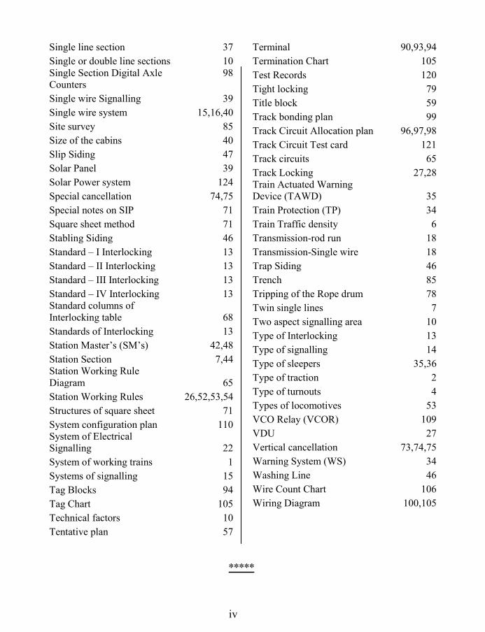
iv
Single line section 37
Single or double line sections 10 Single Section Digital Axle Counters
98
Single wire Signalling 39
Single wire system 15,16,40
Site survey 85
Size of the cabins 40
Slip Siding 47
Solar Panel 39
Solar Power system 124
Special cancellation 74,75
Special notes on SIP 71
Square sheet method 71
Stabling Siding 46
Standard – I Interlocking 13
Standard – II Interlocking 13
Standard – III Interlocking 13
Standard – IV Interlocking 13 Standard columns of Interlocking table 68
Standards of Interlocking 13
Station Master’s (SM’s) 42,48
Station Section 7,44 Station Working Rule Diagram 65
Station Working Rules 26,52,53,54
Structures of square sheet 71
System configuration plan 110 System of Electrical Signalling 22
System of working trains 1
Systems of signalling 15
Tag Blocks 94
Tag Chart 105
Technical factors 10
Tentative plan 57
Terminal 90,93,94
Termination Chart 105
Test Records 120
Tight locking 79
Title block 59
Track bonding plan 99
Track Circuit Allocation plan 96,97,98
Track Circuit Test card 121
Track circuits 65
Track Locking 27,28 Train Actuated Warning Device (TAWD) 35
Train Protection (TP) 34
Train Traffic density 6
Transmission-rod run 18
Transmission-Single wire 18
Trap Siding 46
Trench 85
Tripping of the Rope drum 78
Twin single lines 7
Two aspect signalling area 10
Type of Interlocking 13
Type of signalling 14
Type of sleepers 35,36
Type of traction 2
Type of turnouts 4
Types of locomotives 53
VCO Relay (VCOR) 109
VDU 27
Vertical cancellation 73,74,75
Warning System (WS) 34
Washing Line 46
Wire Count Chart 106
Wiring Diagram 100,105
*****

v
Indian Railway Signal Engineering Volume – III
SECTION – I: SYSTEM OF MECHANICAL SIGNALLING (SINGLE WIRE)
7 x 7 wire rope 28
A1 - Type signal arm 50
A2 - Type signal arm 50
Adjustable crank 41
Adjustable straight arm crank 42
Auxiliary Weight 69
B1 - Type signal arm 53
B2 - Type signal arm 53
Back Light Screen 51,53
Back Tail 5
Back Weight 5
Balancing Weight 69
Boom 76,68
Boom Stand with Boom Lock 69
Bracket Signal Main Posts 46
Bracket Signal Posts 46
Cabin wire adjuster 31
Cast Iron Signal Base 45
Catch Box 12
Catch Handle 12,13,15 Catch Handle locking interlocking frame 15
Catch Rod 12 Change of Direction of the Rod 35 Change of Direction of the Wire 29 Channel iron Bracket Main Signal Post 46
Channel Iron Lead-out 23
Clearance Bar 62
Conflicting notches 7 Correspondence of Signal with lever 59
Counter Weight 49
Counter Weight Bracket 50,53
Counter Weight Lever 49,53
Creep 41
Crossover 54
Diamond 9
Direct lever locking 2
Dolls 46
Double wire lever 43
Double wire system 2,13
Down Rod 49,52
Driving Attachment 60,61
Driving Rod 61 Economical Facing Point Lock 59
Effective length of the rod 41
Equal arm right angle crank 38
E-Type Locks 64,66
Extended Bracket 61
Eye joint 32
Facing point lock 42,56,57
Fixing the E-Type lock 65
Flange Connecting Rod 61
Fouling Bar 62
Front Tail 5,12
Galvanised Iron (GI) wire 22,28
Goose Neck 34
Ground lever frame 11,12
Hand Plunger Lock 64 Hand plunger type double way 65
Hand plunger type one way 65
Holding Bar 61
Inside Lead-out 23,24,25
Interlocking Arrangement 6,18
Interlocking bars 11,21
Interlocking frame 15

vi
Interlocking through Key Plunger 64
Joining of Wires 28
Joint flush 33
Joint Solid 33
Joint wide 33
Key Lock facing Points 65
Ladder & Ladder foundation 47
Lamp Bracket 51,52 Lattice Bracket Main Signal Post 46
Lead-out 22
Lead-out Plates 23
Lever 2,12,15
Lever shoe 5,12,17
Lifting Barrier 67
Limits for point operation 43
Lock 7
Lock Bar 60
Lock Bar Clip 60
Lock Bar/Holding Bar 42
Locking Box 6,12,18
Locking Devices 54
Locking Plunger (Tappet) 6,8,19
Locks of sorts 11,20
Long Joint 33
Lug eye 33
Mechanical signalling 2 Mechanically operated lifting barriers 66
Media of transmission 22
Monitoring Devices 54,63
Number Plate 12
Numbering of the channels 10,21
Operation of points 42
Out side Lead-out 25,26
Pedestal 68
Pinnacle 47
Plunger 12
Point 54
Point adjusting screw 33
Point Detector 55
Point rod coupling 34
Precautions while laying wire 31
Pulley Stakes 29
Quadrant 3,12,17
Quadrant Supports 17
Relief Crank 35
Rocker Arm 60
Rod 32
Rod compensation 36
Rod compensation plan 38,39
Rod Compensator 37
Rod joints 32 Rod passing under level crossing gate 35 Rod passing under track circuit 35
Rod run 22,31
Safety Devices 54
Security of Interlocking 10,21
Semaphore Bearing 51
Semaphore Bracket 48
Semaphore signal fittings 48,51
Semaphore Spectacle 48,51
Shaft 6,12,17,18
Shaft Cap 18
Shoe 55
Signal 44
Signal Arm 50,53
Signal fittings 44
Signal Gantry 47
Signal Lamp & Lamp Bracket 50
Signal post Lattice 45
Signal post Tubular 45
Single wire lever 43
Slackness permissibility 3,15
Smith Welding 43
Solid Rod 32
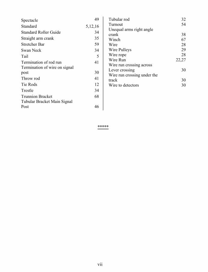
vii
Spectacle 49
Standard 5,12,16
Standard Roller Guide 34
Straight arm crank 35
Stretcher Bar 59
Swan Neck 34
Tail 5
Termination of rod run 41 Termination of wire on signal post 30
Throw rod 41
Tie Rods 12
Trestle 34
Trunnion Bracket 68 Tubular Bracket Main Signal Post 46
*****
Tubular rod 32 Turnout 54 Unequal arms right angle crank 38 Winch 67 Wire 28 Wire Pulleys 29 Wire rope 28 Wire Run 22,27 Wire run crossing across Lever crossing 30 Wire run crossing under the track 30 Wire to detectors 30

viii
Indian Railway Signal Engineering Volume – III
SECTION – II: SYSTEM OF MECHANICAL SIGNALLING (DOUBLE WIRE)
Adjustable screws 100
Affect of wire breakage 115
Affects of tripping 114
Angled Rope Wheel 98
Auxiliary Lever 80
Ball-Knob 83
Block 82
Break in coupling loops 117 Break in transmission of paired wire 120
Broken Wire Lock Design 105,106
Broken Wire Protection 115,116,119 Broken wire protection for Point 121
Broken wire stroke 94
Catch 82
catch handle 74
Catch Rod 82
Clutch 78
Clutch lever 116
Clutch type lever 76 Coupled Wire-loop Compensator 96
Coupling arrangement 86
Coupling end 83
Coupling of levers 85
Crank 75,80
Crank axle 80,82
Detectors 116
Direct type lever 73
Diversion wheel 98
Double Wire Compensator 90,93 Double wire signalling system 72 Double Wire Vertical Rotary Detector 101
Eccentric 110 Economical facing point Lock 123 Economical type Point Mechanism 104
Facing Point Lock 106,122
Gain Stroke Lever 94
Galvanised Signal Wire 89
Handle 82
Holding the route 123
Identification of joints 99,100
Inside Lead-out 94
Interlocking Arrangements 84
Joining of Wires 90
Latch Rod 74,78,82
Left hand signal mechanism 111
Lever 72,73
Lever Drum Lock 87
Lever Frame 72,84
Lever Handle 73,82
Link 74,94
Link rod 78
Lock-bar 123
Locking Boxes 85
Major parts of the lever 83
Mechanism Drum Lock 111
Miniature Lever 83,84 Movement in case wire breakage 115 Non-Economical type of Point Mechanism 103
Outside Lead-out 97
Pinion Disk 82
Pinion Sector 82
Pitch 85
Point 116

ix
Point Mechanism 103
Postulates of interlocking 116
Pull wire 117
Pulley Stakes 97
Pulleys 97
Pull-Pull arrangement 111,112
Pull-pull coupling of levers 85,87
Pull-Pull transmission 100
Push-Pull arrangement 112,113 Push-Pull coupling arrangement 117
Push-Pull coupling of levers 86
Push-Pull transmission 100
Quadrant 82
Rack & pinion Lever 81
Ratchet rod 91
right hand signal mechanism 111
Rod Transmission 107
Rope Drum 73,76,78
Rope Drum trips 79
Rope Wheel 98
Rotary Detector 117
Signal Mechanism 110 Signal Post
110
Signal with the lever normal 116
Signals 109
Signals Lower Quadrant 109 Signals Multiple Aspect Upper Quadrant 109 Single Wire-loop Compensator 96
Spring 78
Standard 80,82
Straight run 98
Stroke 85
Three-To-One lever 78,80
Transmission & Devices 89
Transmission of Single lever 100
Tripping 78
Tripping of the Rope drum 79 Type of Double Wire compensators 92
Wheel Guide 99
Wheels 97
Wire 89
Wire breakage 93,114
Wire Pulley 98
Wire Rope 6 x 19 ¼ 89
Wire Run 89,90
Wire transmission 100
*****
About this book
The book in your hands is combined binding of Volume-II & Volume-III of Indian Railway Signal Engineering completing the book on Indian Railway Signal Engineering with all four volumes. Volume-II of the book,
running in 143 pages covered in 4 chapters, is all about Planning And Designing of signalling system, covered by 47 major illustrative drawings, 11 tables and 22 plans, which is not available outside drawing offices of the General Manager’s headquarter office and to the limited extent in divisional headquarters. Major features of the book are standardisation of Station Working Rules by Railway Board, site survey for locating Cabin/SM’s office, interaction with Commissioner of Railway Safety for opening new railways, introduction and amending installations, plans for introduction/modification of the mechanical, electrical and Electronic signalling systems, including track circuits & cable testing test records covered by 26 such plans and 13 appendices. Volume-III covers double wire system of signalling, supported by 82 major drawings of mechanical signalling. Single Wire system of signalling is covered under Section-I and Double Wire is covered under Section-II. Main features of single wire being Interlocking Table prepared by square Sheet Method as well as by Logic, Interlocking Charts, direct and catch handle type lever frames and associated problems of conflicting notches; signal posts, gantry, rod compensation plans related to ambient temperature variations; and for system of double wire signalling, direct and catch handle type lever frames, tight and loose locking, double wire compensators, signal & point mechanisms, push- pull & pull-pull coupling, broken wire protection, and many more features.
Opinion about the book So far as Planning and Designing of signalling system is concerned, it is an extremely nice step to organise this part which is scattered around with different practices observed by railways.....Making the practice of designing shall be available in one place through this book........I find that the system of mechanical signalling covered under two sections, first being for single wire and second being for double wire, has done justice to the subject...... A.K. Misra Addl. Member (Telecom) Railway Board. It is the need of hour to organise the subject of Planning and Designing of signalling system which has been done by the author, in the book. He accordingly has listed 27 such plans to be prepared to cover different schemes and streams of Signalling system for all systems ranging between mechanical system of signalling with single and double wire system, relay based electrical system of signalling and Electronic system of signalling............. M. Suresh Addl. Member (Sig) Railway Board
About the author Pramod P. Goel, the author of these books is BSc, MBA and Member IETE. He retired as Deputy Chief Signal & Telecom Engineer (SG) having served Indian Railways for about 40 years. During this period he worked in construction organisation for about nine years and for about thirteen years in Central Organisation for Railway Electrification. After retirement he worked with RITES for about one year and then got associated with the prestigious work of modernisation of signalling system in Ghaziabad - Kanpur section as Consultant to a renowned firm associated with. Over the period he has gathered an excellent multi dimensional blend of experience in Signal & Telecom Engineering.
Other volumes of the book, by the same author under publication:
Electronic interlocking: Contain system of Electronic interlocking to be authored jointly by: S.C. Mishra, and Pramod P. Goel.
Photo graph of PP Goel

Opinion on 1st Volume of the book
I find that the lucid coverage of railway signalling system; system of working...essentials of interlocking..has been made in this book and topics have been explained very concisely with supporting diagrams. References are given to the latest General Rule book.....schedule of dimensions are sorted out and tabulated with specific reference to signalling system...overall, to the point presentation of the subjects, concise contents and handy size of the book shall be very useful as ready reference..... Mahabir Prashad The then Addl. Member (Signal) Railway Board
..............Presentation of the subject is illustrative and to the point. I feel the book shall not only be useful to the S&T Engineer but also to Operating Managers.....the book shall be a good reference in day-to-day practice of signal Engineering while it shall also be helpful in preparation of departmental examinations....
P.K. Srivastav Principal CSTE North Central Railway
Opinion on 1Vth
Volume of the book I find that EI, the black box, which is the future system of interlocking coming fast, as covered under an independent chapter, gives a fairly good idea of the system and the subject has been covered in considerable length which shall be very use full for consumption of Railway Signal Engineers …… OFC has been in use of electrical and electronic system of interlocking as transmission media and has been usually considered basically under the domain of telecommunication. Addition of knowledge of OFC manufacture, working , joining, transmission and measurement shall serve purpose big way for signalling system to adopt this media of transmission by signal engineer as well...I consider this volume of the book to be useful for ready reference for signal engineers. P.K. Srivastav, Principal CSTE North Central Railway
I took three readings of the Volume-I, of the book and cleared written examination for LGS. R.K. Mishra The then CTI/HQ
NCR
First volume was organised and well written. By what time IVth volume of the book shall be available? Many LGS and LDCE aspirants