Embed Size (px)
DESCRIPTION
Indian Plan for Contribution in Superconducting Cavity & Cryomodule Technology. Prashant Khare Avinash Puntambekar RRCAT,India. THANKS. At the outset For the great learning opportunity. GDE Effort in cavity & Cryomodule. Cryomodule package. Cryogenic system package. Cavity package. - PowerPoint PPT Presentation
Citation preview
Indian Plan for Indian Plan for Contribution inContribution in
Superconducting Cavity & Superconducting Cavity & Cryomodule TechnologyCryomodule Technology
Prashant KharePrashant Khare
Avinash PuntambekarAvinash Puntambekar
RRCAT,India.RRCAT,India.

THANKSTHANKS
At the outsetAt the outset
For the great learning For the great learning opportunity.opportunity.
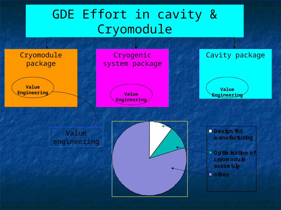
GDE Effort in cavity & Cryomodule
Cryomodule package
Value engineering
Cryogenic system package
Cavity package
Value EngineeringValue Engineering
Design formanufacturing
Optimisation ofcryomoduleassembly
other
Value Engineering
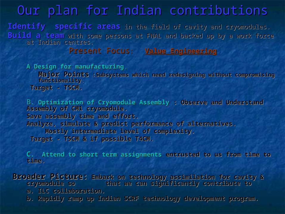
Our plan for Indian contributionsOur plan for Indian contributions Identify specific areasIdentify specific areas in the field of cavity and cryomodules. in the field of cavity and cryomodules.
Build a teamBuild a team with some persons at FNAL and backed up by a work force at with some persons at FNAL and backed up by a work force at Indian centres.Indian centres.
Present FocusPresent Focus: : Value EngineeringValue Engineering
A Design for manufacturingA Design for manufacturing..Major PointsMajor Points :Subsystems which need redesigning without :Subsystems which need redesigning without compromising functionalitycompromising functionality..
Target - T5CM.Target - T5CM.
BB. Optimization of Cryomodule Assembly. Optimization of Cryomodule Assembly : Observe and Understand : Observe and Understand Assembly of CM1 cryomodule. Assembly of CM1 cryomodule. Save assembly time and effort.Save assembly time and effort.Analyze, simulate & predict performance of alternatives.Analyze, simulate & predict performance of alternatives.
Mostly intermediate level of complexity.Mostly intermediate level of complexity. Target - T5CM & if possible T4CM. Target - T5CM & if possible T4CM.
CC. Attend to short term assignments. Attend to short term assignments entrusted to us from time to entrusted to us from time to time. time.
Broader Picture:Broader Picture: Embark on technology assimilation for cavity & Embark on technology assimilation for cavity & cryomodule so cryomodule so that we can significantly contribute to that we can significantly contribute to
a. ILC collaboration.a. ILC collaboration. b. Rapidly ramp up Indian SCRF technology development program.b. Rapidly ramp up Indian SCRF technology development program.
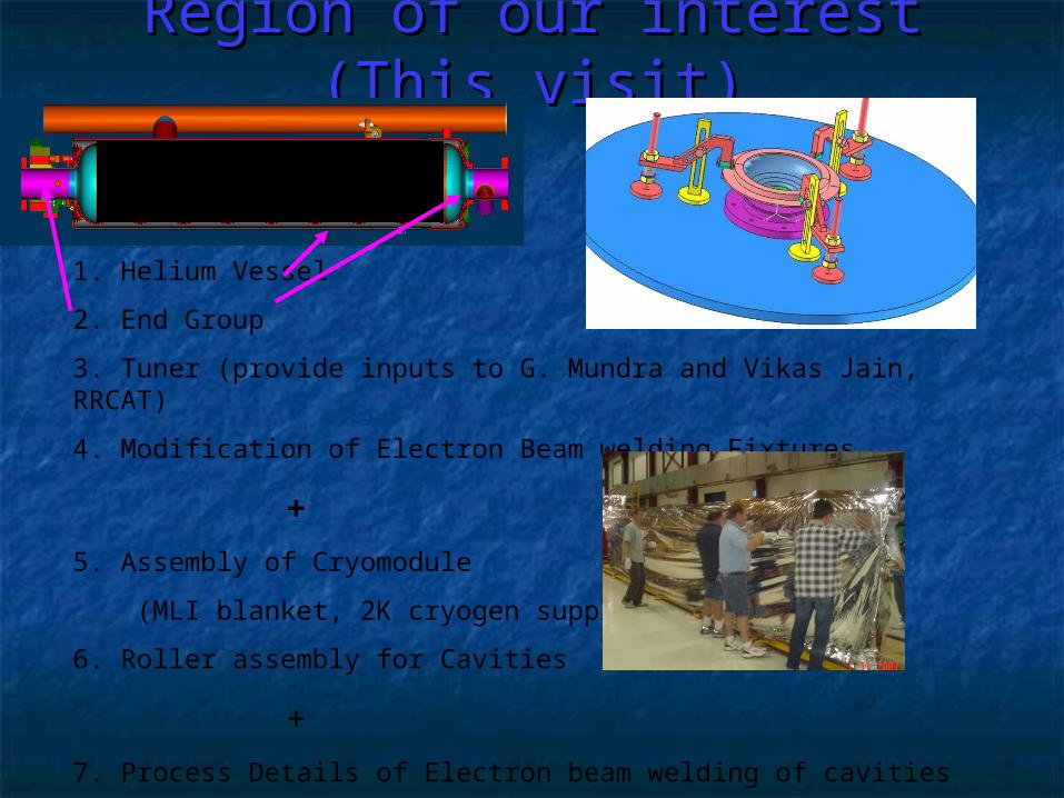
Region of our interest (This Region of our interest (This visit)visit)
1. Helium Vessel
2. End Group
3. Tuner (provide inputs to G. Mundra and Vikas Jain, RRCAT)
4. Modification of Electron Beam welding Fixtures
+5. Assembly of Cryomodule
(MLI blanket, 2K cryogen supply pipe)
6. Roller assembly for Cavities
+7. Process Details of Electron beam welding of cavities
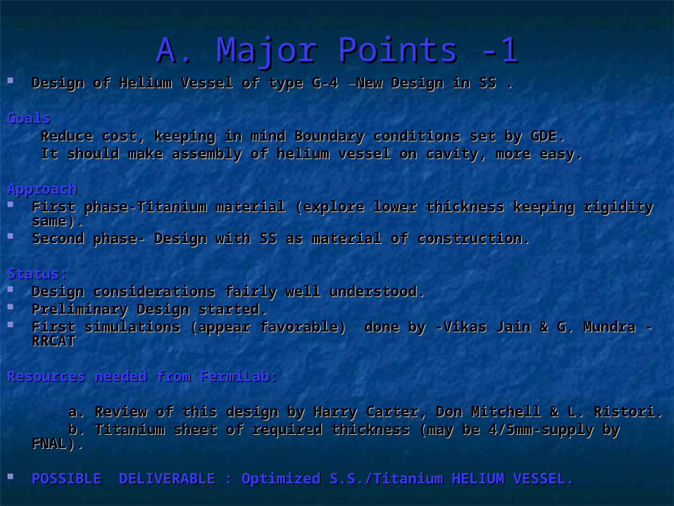
A. Major Points -1A. Major Points -1 Design of Helium Vessel of type G-4Design of Helium Vessel of type G-4 – –New Design in SS .New Design in SS .
GoalsGoals Reduce cost, keeping in mind Boundary conditions set by GDE. Reduce cost, keeping in mind Boundary conditions set by GDE. It should make assembly of helium vessel on cavity, more easy.It should make assembly of helium vessel on cavity, more easy.
ApproachApproach First phase-Titanium material (explore lower thickness keeping rigidity First phase-Titanium material (explore lower thickness keeping rigidity
same). same). Second phase- Design with SS as material of construction.Second phase- Design with SS as material of construction.
Status:Status: Design considerations fairly well understood. Design considerations fairly well understood. Preliminary Design started.Preliminary Design started. First simulations (appear favorable) done by -Vikas Jain & G. Mundra -First simulations (appear favorable) done by -Vikas Jain & G. Mundra -
RRCATRRCAT
Resources needed from FermiLab:Resources needed from FermiLab:
a. Review of this design by Harry Carter, Don Mitchell & L. Ristori.a. Review of this design by Harry Carter, Don Mitchell & L. Ristori. b. Titanium sheet of required thickness (may be 4/5mm-supply by FNAL).b. Titanium sheet of required thickness (may be 4/5mm-supply by FNAL).
POSSIBLE DELIVERABLE : Optimized S.S./Titanium HELIUM VESSEL.POSSIBLE DELIVERABLE : Optimized S.S./Titanium HELIUM VESSEL.
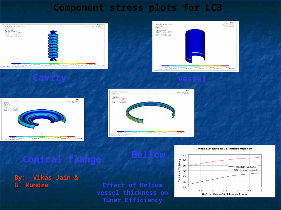
Component stress plots for LC3
Cavity
Conical flange Bellow
Vessel
Vessel thickness Vs Tuner efficiency
85
86
87
88
89
90
91
2 2.5 3 3.5 4 4.5 5
Helium Vessel thickness in mm
Tu
ne
r e
ffic
ien
cy
in
%
Ti Heluim vessel
SS Heluim vessel
Effect of Helium vessel thickness on Tuner
Efficiency
By: Vikas Jain &By: Vikas Jain &G. MundraG. Mundra
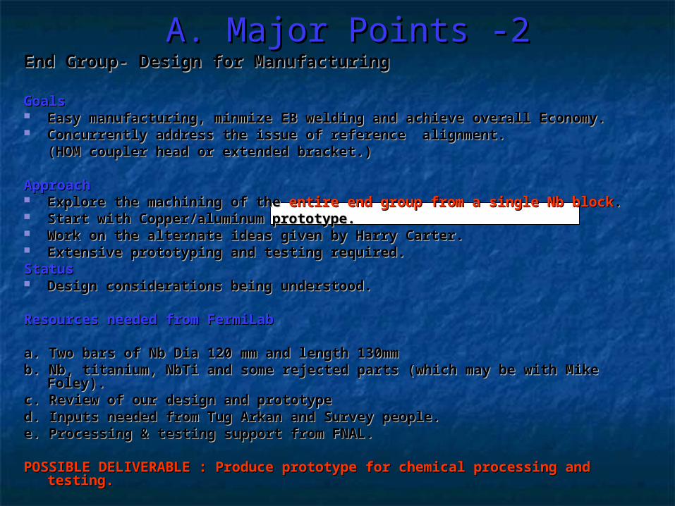
A. Major Points -2A. Major Points -2End Group- Design for Manufacturing End Group- Design for Manufacturing
GoalsGoals Easy manufacturing, minmize EB welding and achieve overall Economy.Easy manufacturing, minmize EB welding and achieve overall Economy. Concurrently address the issue of reference alignment. Concurrently address the issue of reference alignment.
(HOM coupler head or extended bracket.) (HOM coupler head or extended bracket.)
ApproachApproach Explore the machining of the Explore the machining of the entire endentire end group from a single Nb blockgroup from a single Nb block. . Start with Copper/aluminum prototype.Start with Copper/aluminum prototype. Work on the alternate ideas given by Harry Carter.Work on the alternate ideas given by Harry Carter. Extensive prototyping and testing required.Extensive prototyping and testing required.StatusStatus Design considerations being understood. Design considerations being understood.
Resources needed from FermiLabResources needed from FermiLab
a. Two bars of Nb Dia 120 mm and length 130mma. Two bars of Nb Dia 120 mm and length 130mmb. Nb, titanium, NbTi and some rejected parts (which may be with Mike Foley).b. Nb, titanium, NbTi and some rejected parts (which may be with Mike Foley).c. Review of our design and prototypec. Review of our design and prototyped. Inputs needed from Tug Arkan and Survey people.d. Inputs needed from Tug Arkan and Survey people.e. Processing & testing support from FNAL.e. Processing & testing support from FNAL.
POSSIBLE DELIVERABLE POSSIBLE DELIVERABLE : Produce prototype for chemical processing and testing.: Produce prototype for chemical processing and testing.
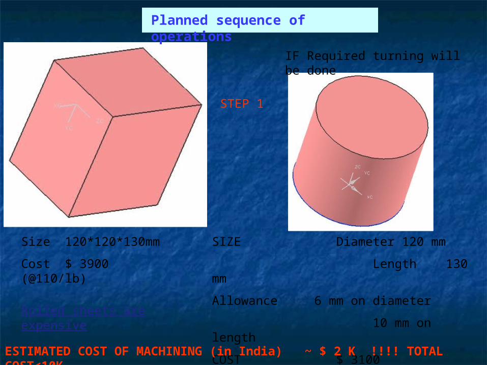
SIZE Diameter 120 mm
Length 130 mm
Allowance 6 mm on diameter
10 mm on length
COST $ 3100 (@$110/lb)
IF Required turning will be done
Size 120*120*130mm
Cost $ 3900 (@110/lb)
STEP 1
Rolled sheets are expensive
ESTIMATED COST OF MACHINING (in India) ~ $ 2 K !!!! TOTAL COST<10K
Planned sequence of operations
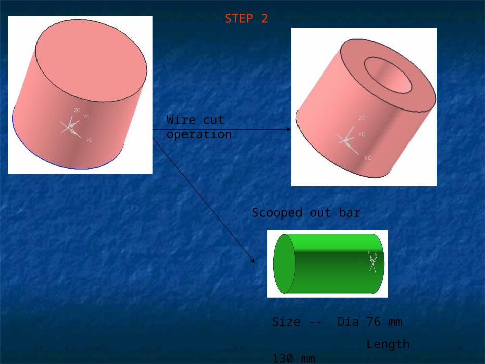
Wire cut operation
Size -- Dia 76 mm
Length 130 mm
STEP 2
Scooped out bar
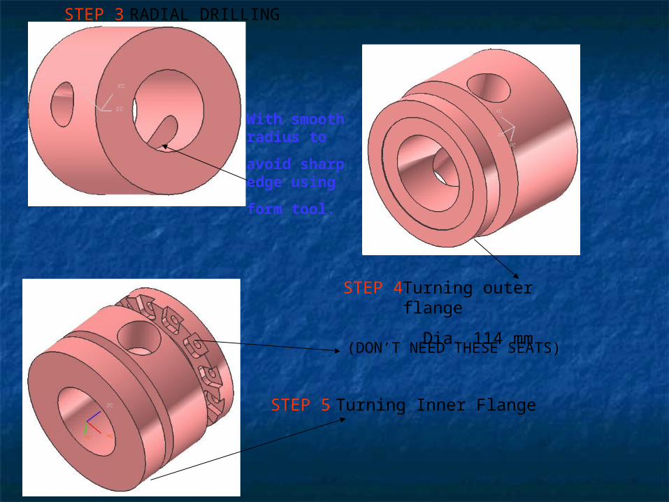
RADIAL DRILLING
Turning outer flange
Dia. 114 mm
Turning Inner Flange
STEP 3
STEP 4
STEP 5
With smooth radius to
avoid sharp edge using
form tool.
(DON’T NEED THESE SEATS)
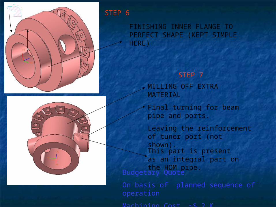
FINISHING INNER FLANGE TO PERFECT SHAPE (KEPT SIMPLE HERE)
MILLING OFF EXTRA MATERIAL
Final turning for beam pipe and ports.
Leaving the reinforcement of tuner port (not shown).
STEP 6
STEP 7
This part is present as an integral part on the HOM pipe.
Budgetary Quote
On basis of planned sequence of operation
Machining Cost ~$ 2 K

DIA 46MM
LENGTH 70MM
DIA 61MM
LENGTH 30
DIA 34MM
LENGTH 18MM
Size -- Dia 76 mm
Length 130mm
STEP 8
STEP 9
STEP 10
Recovery of Flanges from the scooped out bar
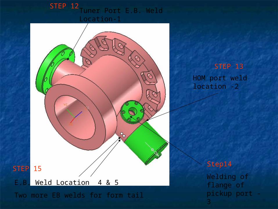
Tuner Port E.B. Weld Location-1
HOM port weld location -2
E.B. Weld Location 4 & 5
Two more EB welds for form tail
STEP 12
STEP 13
Step14
Welding of flange of pickup port -3
STEP 15
Issues to be examinedIssues to be examined
Can we get Nb as a thick hollow cylinder.Can we get Nb as a thick hollow cylinder. Alternatively ,is it available as a bar?Alternatively ,is it available as a bar? Sealing with clamps is a must. If not then suitable Sealing with clamps is a must. If not then suitable
seal has to be developed.seal has to be developed. Alternate option of using existing design of Nb-Ti Alternate option of using existing design of Nb-Ti
flange is always available.flange is always available. Further cost reduction if scrap Nb can be Further cost reduction if scrap Nb can be
recycled.recycled.
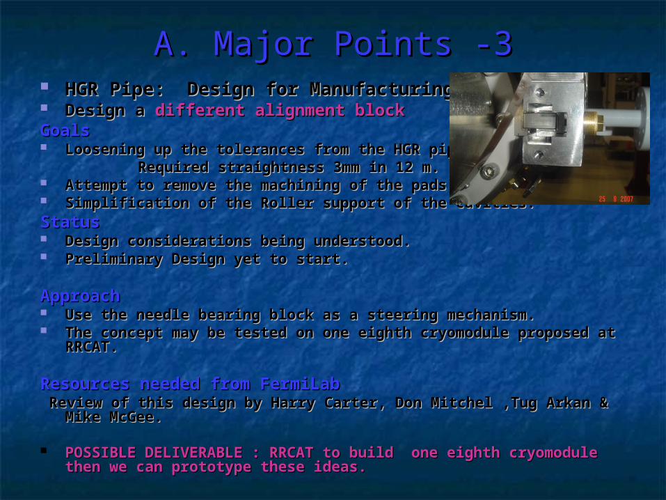
A. Major Points -3A. Major Points -3 HGR Pipe: Design for ManufacturingHGR Pipe: Design for Manufacturing Design a Design a different alignment blockdifferent alignment blockGoalsGoals Loosening up the tolerances from the HGR pipe.Loosening up the tolerances from the HGR pipe. Required straightness 3mm in 12 m.Required straightness 3mm in 12 m. Attempt to remove the machining of the pads.Attempt to remove the machining of the pads. Simplification of the Roller support of the cavities.Simplification of the Roller support of the cavities.StatusStatus Design considerations being understood.Design considerations being understood. Preliminary Design yet to start.Preliminary Design yet to start.
ApproachApproach Use the needle bearing block as a steering mechanism.Use the needle bearing block as a steering mechanism. The concept may be tested on one eighth cryomodule proposed at The concept may be tested on one eighth cryomodule proposed at
RRCAT.RRCAT.
Resources needed from FermiLabResources needed from FermiLab Review of this design by Harry Carter, Don Mitchel ,Tug Arkan & Review of this design by Harry Carter, Don Mitchel ,Tug Arkan &
Mike McGee.Mike McGee.
POSSIBLE DELIVERABLE : RRCAT to build one eighth cryomodule POSSIBLE DELIVERABLE : RRCAT to build one eighth cryomodule then we can prototype these ideas.then we can prototype these ideas.
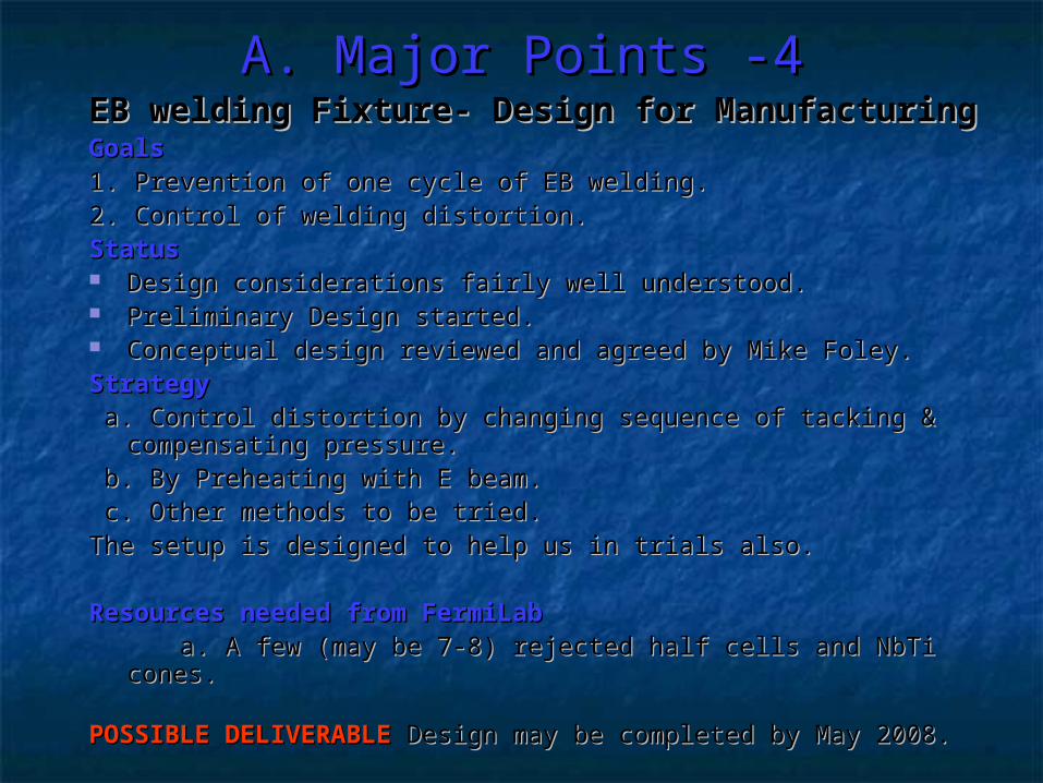
A. Major Points -4A. Major Points -4EB welding Fixture- Design for ManufacturingEB welding Fixture- Design for ManufacturingGoalsGoals1. Prevention of one cycle of EB welding. 1. Prevention of one cycle of EB welding. 2. Control of welding distortion.2. Control of welding distortion.StatusStatus Design considerations fairly well understood. Design considerations fairly well understood. Preliminary Design started. Preliminary Design started. Conceptual design reviewed and agreed by Mike Foley.Conceptual design reviewed and agreed by Mike Foley.StrategyStrategy a. Control distortion by changing sequence of tacking & a. Control distortion by changing sequence of tacking &
compensating pressure.compensating pressure. b. By Preheating with E beam.b. By Preheating with E beam. c. Other methods to be tried.c. Other methods to be tried.The setup is designed to help us in trials also.The setup is designed to help us in trials also.
Resources needed from FermiLabResources needed from FermiLab a. A few (may be 7-8) rejected half cells and NbTi cones.a. A few (may be 7-8) rejected half cells and NbTi cones.
POSSIBLE DELIVERABLE POSSIBLE DELIVERABLE Design may be completed by May 2008.Design may be completed by May 2008.
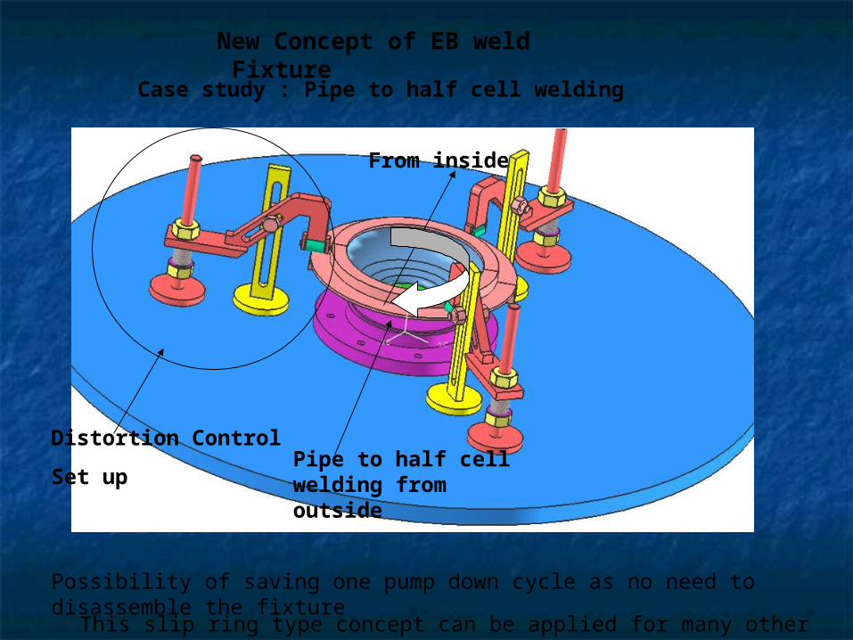
New Concept of EB weld Fixture
Pipe to half cell welding from outside
Case study : Pipe to half cell welding
Distortion Control
Set up
This slip ring type concept can be applied for many other similar application
From inside
Possibility of saving one pump down cycle as no need to disassemble the fixture
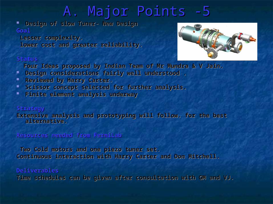
A. Major Points -5A. Major Points -5 Design of slow Tuner- New DesignDesign of slow Tuner- New Design GoalGoal Lesser complexity.Lesser complexity. lower cost and greater reliability. lower cost and greater reliability.
StatusStatus Four Ideas proposed by Indian Team of Mr Mundra & V Jain.Four Ideas proposed by Indian Team of Mr Mundra & V Jain. Design considerations fairly well understood .Design considerations fairly well understood . Reviewed by Harry Carter.Reviewed by Harry Carter. Scissor concept selected for further analysis.Scissor concept selected for further analysis. Finite element analysis underwayFinite element analysis underway
StrategyStrategyExtensive analysis and prototyping will follow. for the best alternative.Extensive analysis and prototyping will follow. for the best alternative.
Resources needed from FermiLabResources needed from FermiLab
Two Cold motors and one piezo tuner set.Two Cold motors and one piezo tuner set.Continuous interaction with Harry Carter and Don Mitchell.Continuous interaction with Harry Carter and Don Mitchell.
DeliverablesDeliverablesTime schedules can be given after consultation with GM and VJ.Time schedules can be given after consultation with GM and VJ.
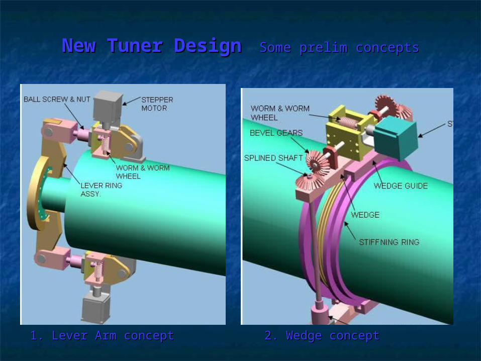
New Tuner DesignNew Tuner Design Some prelim conceptsSome prelim concepts
2. Wedge concept2. Wedge concept1. Lever Arm concept1. Lever Arm concept
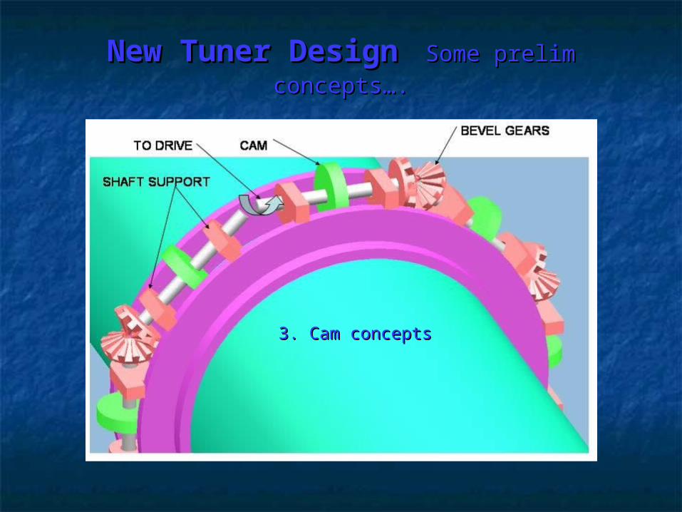
3. Cam concepts3. Cam concepts
New Tuner DesignNew Tuner Design Some prelim Some prelim concepts….concepts….
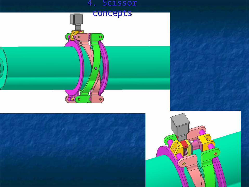
4. Scissor concepts4. Scissor concepts
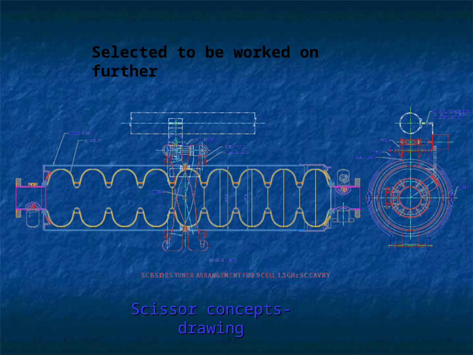
Scissor concepts- Scissor concepts- drawingdrawing
Selected to be worked on further
A. Major Points -6A. Major Points -6
GoalsGoals Explore the development of transition joint between SS and Explore the development of transition joint between SS and
Niobium. Niobium. Explore brazed copper joint and Explosion bonding.Explore brazed copper joint and Explosion bonding. Design considerations being understood.Design considerations being understood. The most challenging task. The most challenging task. Two joints, helium vessel to 2K pipe and helium vessel to Two joints, helium vessel to 2K pipe and helium vessel to
Nb cavities being considered.Nb cavities being considered.
Resources needed from FermiLab.Resources needed from FermiLab. Evaluation of test pieces.Evaluation of test pieces.
Deliverables : Understandably no dates can be given for Deliverables : Understandably no dates can be given for this task.this task.
B. Optimisation of assemblyB. Optimisation of assembly Titanium pipe welding of bellows.Titanium pipe welding of bellows.
MLI blanket MLI blanket a. Pre-stitched, 1/8 length put on Big Bertha.a. Pre-stitched, 1/8 length put on Big Bertha. b. 2K line & coupler..b. 2K line & coupler..
Assembly of roller bearingsAssembly of roller bearings. .
If the blade tuner is to be used the assembly can be If the blade tuner is to be used the assembly can be simplified.simplified.
Invar post locking bracket design.Invar post locking bracket design.
Gate valve support to be done againGate valve support to be done again
Lot of rework effort goes into magnetic shield fitment.Lot of rework effort goes into magnetic shield fitment.
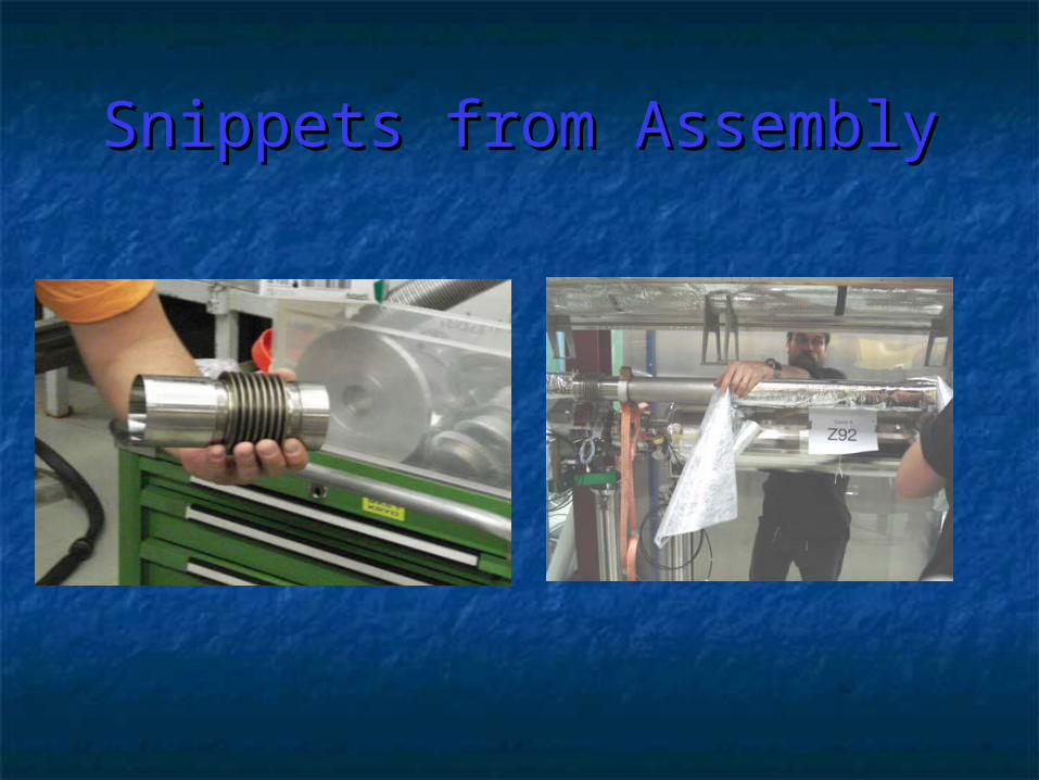
Snippets from AssemblySnippets from Assembly
V.E.1V.E.1
Assembly of 2K supply lineAssembly of 2K supply line
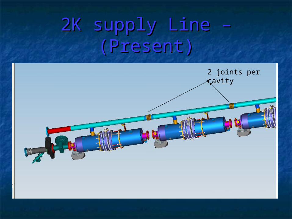
2K supply Line – (Present)2K supply Line – (Present)
2 joints per cavity
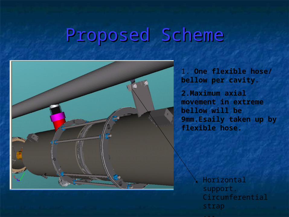
Proposed SchemeProposed Scheme
1. One flexible hose/ bellow per cavity.
2.Maximum axial movement in extreme bellow will be 9mm.Esaily taken up by flexible hose.
Horizontal support. Circumferential strap
Allows contraction
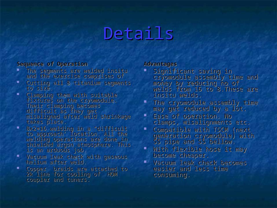
DetailsDetails
Sequence of OperationSequence of Operation The segments are welded insitu The segments are welded insitu
and the exercise comprises ofand the exercise comprises of Cutting all 8 titanium segments to Cutting all 8 titanium segments to
size.size. Clamping them with suitable Clamping them with suitable
fixtures on the cryomodule. Their fixtures on the cryomodule. Their clamping becomes difficult as they clamping becomes difficult as they get misaligned after weld get misaligned after weld shrinkage takes place. shrinkage takes place.
8x2=16 welding in a “difficult to 8x2=16 welding in a “difficult to approach’ location. All the welding approach’ location. All the welding operations are done in shielded operations are done in shielded argon atmosphere. This is an argon atmosphere. This is an arduous job.arduous job.
Vacuum leak check with gaseous Vacuum leak check with gaseous helium after weld. helium after weld.
Copper braids are attached to 2k Copper braids are attached to 2k line for cooling of HOM coupler line for cooling of HOM coupler and tuners.and tuners.
AdvantagesAdvantages Significant saving in cryomodule Significant saving in cryomodule
assembly time and money by assembly time and money by reducing no of welds from 16 to reducing no of welds from 16 to 8.These are insitu welds.8.These are insitu welds.
The cryomodule assembly time The cryomodule assembly time may get reduced by a lot. may get reduced by a lot.
Ease of operation. No clamps, Ease of operation. No clamps, misalignments etc.misalignments etc.
Compatible with T5CM (next Compatible with T5CM (next generation cryomodule) with SS generation cryomodule) with SS pipe and SS bellow.pipe and SS bellow.
With flexible hose it may With flexible hose it may become cheaper.become cheaper.
Vacuum leak check becomes Vacuum leak check becomes easier and less time consuming.easier and less time consuming.

V.E.2V.E.2New concept for making MLI New concept for making MLI
blankets & It’s Assemblyblankets & It’s Assembly
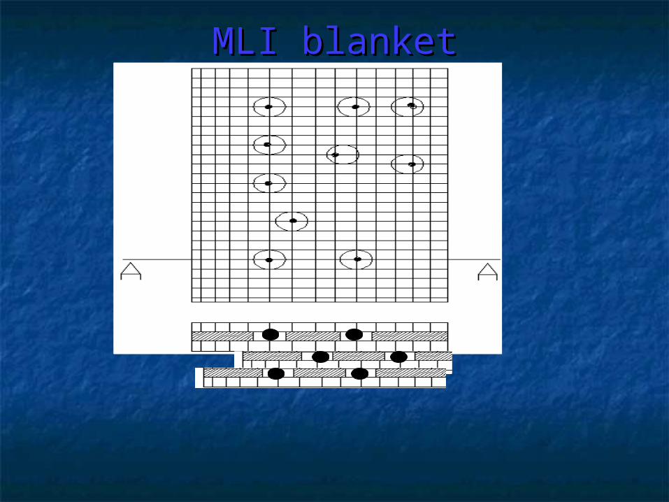
MLI blanketMLI blanket
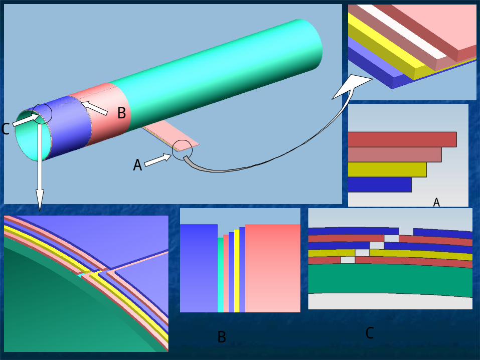
A
A
B C
CB
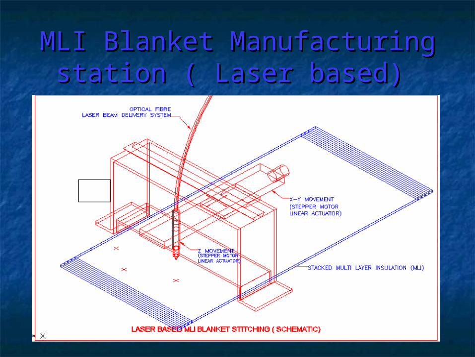
MLI Blanket ManufacturingMLI Blanket Manufacturingstation ( Laser based) station ( Laser based)
DetailsDetailsThis scheme will address following IssuesThis scheme will address following Issues It is a rough guess that the assembly of 30 layer blanket It is a rough guess that the assembly of 30 layer blanket
can be performed in half a day.can be performed in half a day. It will be significantly better from heat leak point of view as It will be significantly better from heat leak point of view as
there will be negligible chances of outer layer coming in there will be negligible chances of outer layer coming in contact with vacuum vessel.contact with vacuum vessel.
MLI wrapping procedure will also save at least 1 hour per MLI wrapping procedure will also save at least 1 hour per coupler.coupler.
The cost of MLI blanket will be significantly less than that The cost of MLI blanket will be significantly less than that of MLI blankets available from industry because of of MLI blankets available from industry because of automation due to laser and lesser no. of workers needed.automation due to laser and lesser no. of workers needed.
V.E.3V.E.3
Roller Bearing assemblyRoller Bearing assembly
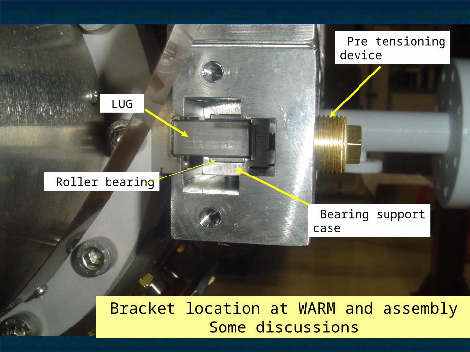
Roller bearing
Bearing supportcase
Pre tensioningdevice
LUG
Bracket location at WARM and assembly Some discussions
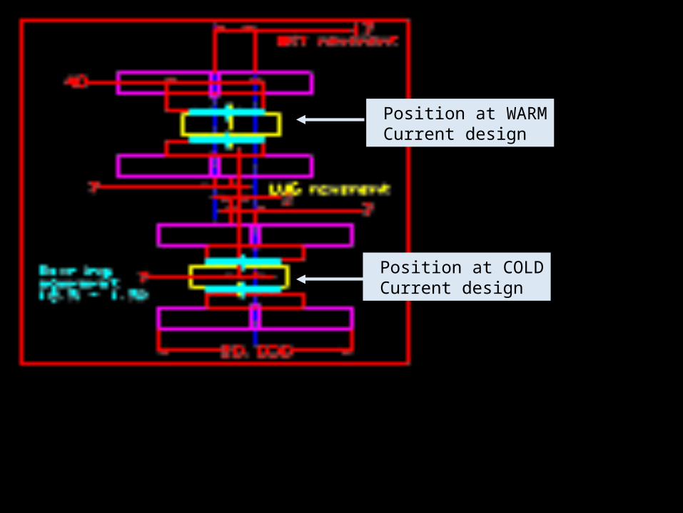
Position at WARM Current design
Position at COLD Current design
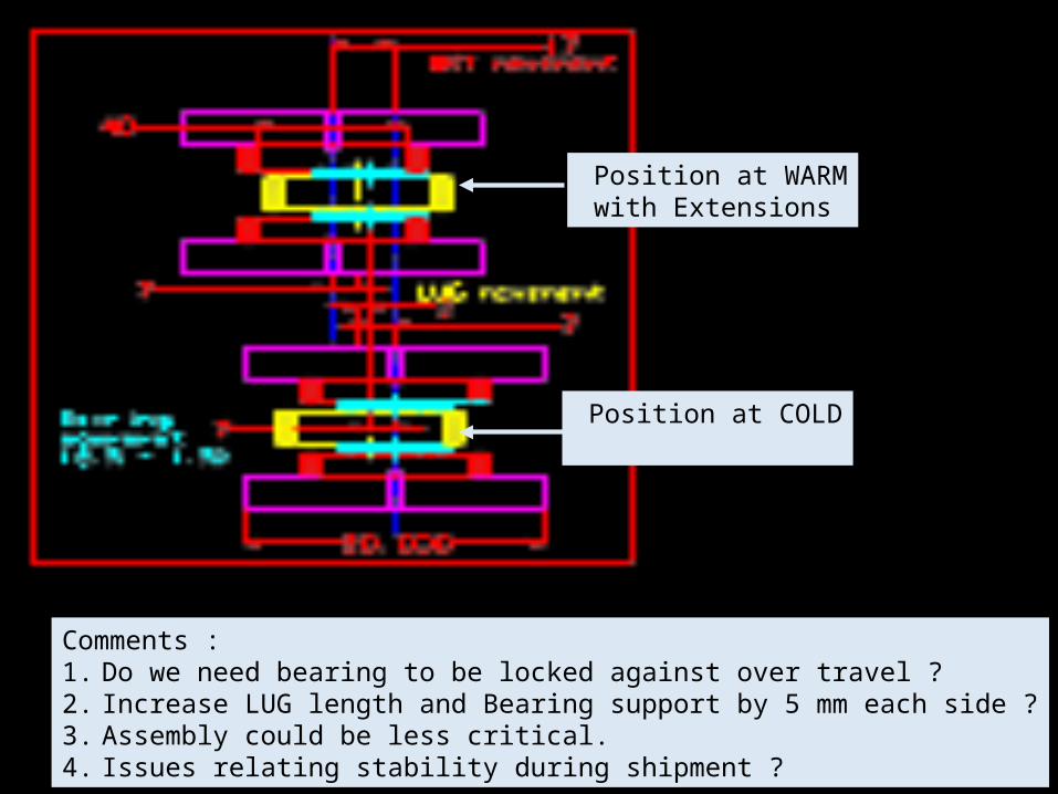
Comments :1. Do we need bearing to be locked against over travel ?2. Increase LUG length and Bearing support by 5 mm each side ?3. Assembly could be less critical.4. Issues relating stability during shipment ?
Position at WARM with Extensions
Position at COLD
DetailsDetails
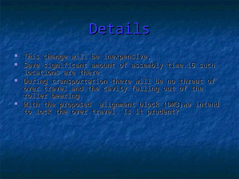
This change will be inexpensive,This change will be inexpensive, Save significant amount of assembly time.16 such locations Save significant amount of assembly time.16 such locations
are there.are there. During transportation there will be no threat of over travel During transportation there will be no threat of over travel
and the cavity falling out of the roller bearing. and the cavity falling out of the roller bearing. With the proposed alignment block (DM3)we intend to lock With the proposed alignment block (DM3)we intend to lock
the over travel. Is it prudent?the over travel. Is it prudent?
C. Assignments Given & C. Assignments Given & CompletedCompleted
Thermal contraction recalculation for subsystems of 1.3GHzThermal contraction recalculation for subsystems of 1.3GHz
cryomodule. COMPLETED.cryomodule. COMPLETED. Thermal contraction calculation for 3.9GHz cryomodule to Thermal contraction calculation for 3.9GHz cryomodule to
understand new position of couplers- COMPLETED.understand new position of couplers- COMPLETED. Proposed -Piping Connection alteration for 3.9 GHz –Proposed -Piping Connection alteration for 3.9 GHz –
PENDING.PENDING.

October 9, 2007October 9, 2007 SUMMARY OF CRYMODULE CALCULATIONS ON THERMAL SHRINKAGESUMMARY OF CRYMODULE CALCULATIONS ON THERMAL SHRINKAGE After checking the spreadsheet, there are certain changes that we would like to propose After checking the spreadsheet, there are certain changes that we would like to propose 1. In the earlier sheet, coefficient of thermal contraction (α) taken for all calculations is the 1. In the earlier sheet, coefficient of thermal contraction (α) taken for all calculations is the
one at room temp. As the value of (α) changes drastically as we reduce the temp, it may one at room temp. As the value of (α) changes drastically as we reduce the temp, it may be better if we use cumulative thermal contraction factor from room temp to 2 K.be better if we use cumulative thermal contraction factor from room temp to 2 K.
MaterialCoeff. Of Linear expansion (alpha)Cumulative thermal expansion coeff factor from( MaterialCoeff. Of Linear expansion (alpha)Cumulative thermal expansion coeff factor from( 300-100)KCumulative thermal expansion coeff factor from( 100-4)KStainless Steel1.73E-300-100)KCumulative thermal expansion coeff factor from( 100-4)KStainless Steel1.73E-05270 E-05 38 E-05Titanium8.9E-06140 E-0517 E-05Invar3.00E-0636 E-05 4 E-05270 E-05 38 E-05Titanium8.9E-06140 E-0517 E-05Invar3.00E-0636 E-05 4 E-05Niobium7.3E-06126E-0522E-0505Niobium7.3E-06126E-0522E-05
This will mean a big change This will mean a big change Ex. Cold mass support shrinkage 4175 * 270E-05 = 11.273 for (300K – 100K)Ex. Cold mass support shrinkage 4175 * 270E-05 = 11.273 for (300K – 100K) 4175 * 38E-05 = 1.587 for (100K – 4K)4175 * 38E-05 = 1.587 for (100K – 4K) Total = 12.86 mmTotal = 12.86 mm Ignoring Integral factor this will amount to 21.668 mm {a difference of 8.8 mm). This is Ignoring Integral factor this will amount to 21.668 mm {a difference of 8.8 mm). This is
closer to reality.closer to reality. 2. Another suggestion is regarding positioning of HGR support location at warm. It is 2. Another suggestion is regarding positioning of HGR support location at warm. It is
proposed that the centre of the lug on the titanium vessel and centre of HGR support proposed that the centre of the lug on the titanium vessel and centre of HGR support bracket coincide at 2 K and a calculated offset is kept in warm position. This will ensure bracket coincide at 2 K and a calculated offset is kept in warm position. This will ensure better equilibrium and freer movement over the bearing. The proposed values are given in better equilibrium and freer movement over the bearing. The proposed values are given in the excel sheet attached.the excel sheet attached.
3. We have calculated contractions values at two different temperatures 300-100 K and 3. We have calculated contractions values at two different temperatures 300-100 K and 100-4 K in addition to total contractions. This could be helpful during tuning adjustment at 100-4 K in addition to total contractions. This could be helpful during tuning adjustment at intermediate temperature. intermediate temperature.
4. From point of view of ease in assembly it may be better if length of needle bearing 4. From point of view of ease in assembly it may be better if length of needle bearing is increased from 30 mm to 50 mm. There is sufficient space on the bracket. So it will not is increased from 30 mm to 50 mm. There is sufficient space on the bracket. So it will not introduce any drawing change. During assembly it will not be necessary to measure very introduce any drawing change. During assembly it will not be necessary to measure very accurately where the lug should sit. There are 16 such assemblies and may be consuming accurately where the lug should sit. There are 16 such assemblies and may be consuming lot of assembly time. We have later consulted Tug Arkan and Chuk Grimm, they agree.lot of assembly time. We have later consulted Tug Arkan and Chuk Grimm, they agree.
5. The position of possible monitoring points (WPM and coupler locations) has been also 5. The position of possible monitoring points (WPM and coupler locations) has been also calculated. This may be cross checked with actual cool down positions during cool down calculated. This may be cross checked with actual cool down positions during cool down for validation of calculations.for validation of calculations.
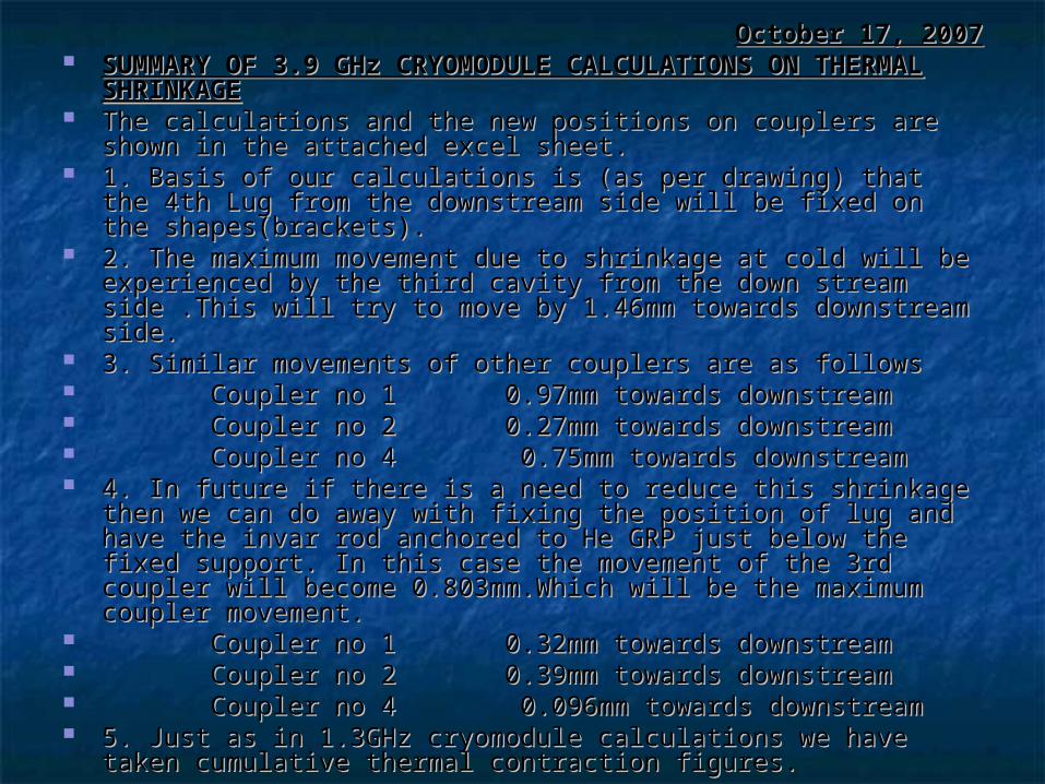
October 17, 2007October 17, 2007 SUMMARY OF 3.9 GHz CRYOMODULE CALCULATIONS ON SUMMARY OF 3.9 GHz CRYOMODULE CALCULATIONS ON
THERMAL SHRINKAGETHERMAL SHRINKAGE The calculations and the new positions on couplers are shown in The calculations and the new positions on couplers are shown in
the attached excel sheet.the attached excel sheet. 1. Basis of our calculations is (as per drawing) that the 4th Lug 1. Basis of our calculations is (as per drawing) that the 4th Lug
from the downstream side will be fixed on the shapes(brackets).from the downstream side will be fixed on the shapes(brackets). 2. The maximum movement due to shrinkage at cold will be 2. The maximum movement due to shrinkage at cold will be
experienced by the third cavity from the down stream side .This experienced by the third cavity from the down stream side .This will try to move by 1.46mm towards downstream side.will try to move by 1.46mm towards downstream side.
3. Similar movements of other couplers are as follows3. Similar movements of other couplers are as follows Coupler no 1 0.97mm towards downstreamCoupler no 1 0.97mm towards downstream Coupler no 2 0.27mm towards downstreamCoupler no 2 0.27mm towards downstream Coupler no 4 0.75mm towards downstreamCoupler no 4 0.75mm towards downstream 4. In future if there is a need to reduce this shrinkage then we can 4. In future if there is a need to reduce this shrinkage then we can
do away with fixing the position of lug and have the invar rod do away with fixing the position of lug and have the invar rod anchored to He GRP just below the fixed support. In this case the anchored to He GRP just below the fixed support. In this case the movement of the 3rd coupler will become 0.803mm.Which will be movement of the 3rd coupler will become 0.803mm.Which will be the maximum coupler movement.the maximum coupler movement.
Coupler no 1 0.32mm towards downstreamCoupler no 1 0.32mm towards downstream Coupler no 2 0.39mm towards downstreamCoupler no 2 0.39mm towards downstream Coupler no 4 0.096mm towards downstreamCoupler no 4 0.096mm towards downstream 5. Just as in 1.3GHz cryomodule calculations we have taken 5. Just as in 1.3GHz cryomodule calculations we have taken
cumulative thermal contraction figures.cumulative thermal contraction figures.
D. Technology AssimilationD. Technology Assimilation A concurrent activity.A concurrent activity. All the “design for manufacturing” tasks will help in this All the “design for manufacturing” tasks will help in this
process (helium vessel design, alignment block design etc)process (helium vessel design, alignment block design etc) Information being gathered on forming and EB welding issues Information being gathered on forming and EB welding issues
of niobium cavities. Design for manufacturing a major of niobium cavities. Design for manufacturing a major consideration.consideration.
A larger participation in cavity processing & testing A larger participation in cavity processing & testing infrastructure.infrastructure.
Thermal shrinkage estimation and how to build the Thermal shrinkage estimation and how to build the cryomodule around it , is well understood. Want to learn cryomodule around it , is well understood. Want to learn radiation shield design and have an overview of ILC radiation shield design and have an overview of ILC cryogenic system.cryogenic system.
Plan to understand cryogenic test facility for cavities so that Plan to understand cryogenic test facility for cavities so that we can upgrade cryogenic test facility at RRCAT.we can upgrade cryogenic test facility at RRCAT.
Interacting with Lance Cooley for SC material R & D.Interacting with Lance Cooley for SC material R & D. Interacting with Mike McGee to understand results of Interacting with Mike McGee to understand results of
cryomodule shipment exercise. Planning to use similar cryomodule shipment exercise. Planning to use similar fixtures for transportation of our cryomodule/subsystems.fixtures for transportation of our cryomodule/subsystems.
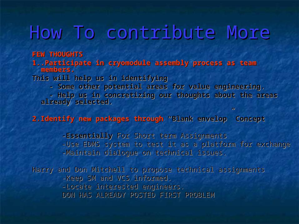
How To contribute MoreHow To contribute MoreFEW THOUGHTSFEW THOUGHTS1..Participate in cryomodule assembly process as team 1..Participate in cryomodule assembly process as team
members. members. This will help us in identifyingThis will help us in identifying - Some other potential areas for value engineering.- Some other potential areas for value engineering. - Help us in concretizing our thoughts about the areas - Help us in concretizing our thoughts about the areas
already selected.already selected. 2.Identify new packages through 2.Identify new packages through “Blank envelop”“Blank envelop” ConceptConcept
-Essentially -Essentially For Short term AssignmentsFor Short term Assignments -Use EDMS system to test it as a platform for exchange-Use EDMS system to test it as a platform for exchange -Maintain dialogue on technical issues.-Maintain dialogue on technical issues.
Harry and Don Mitchell to propose technical assignmentsHarry and Don Mitchell to propose technical assignments -Keep SM and VCS informed.-Keep SM and VCS informed. -Locate interested engineers. -Locate interested engineers.
DON HAS ALREADY POSTED FIRST PROBLEM DON HAS ALREADY POSTED FIRST PROBLEM

Work Plan For Coming Work Plan For Coming MonthsMonths
During VisitDuring Visit Get all technical information on the 6 major issues Get all technical information on the 6 major issues
identified (4 fairly completed and 2 in progress).identified (4 fairly completed and 2 in progress). Obtain views on different Value engineering concepts and Obtain views on different Value engineering concepts and
after return start analyzing how the alternatives thought by after return start analyzing how the alternatives thought by us would work. (completed 3 pending 3)!!!!us would work. (completed 3 pending 3)!!!!
Additional information to be obtained on various topics. Additional information to be obtained on various topics.
After ReturnAfter Return Advance new design concepts for various sub systems & Advance new design concepts for various sub systems &
propose design for review.propose design for review. Propose fabrication of one eighth length cryomodule & build Propose fabrication of one eighth length cryomodule & build
it.it. Start prototyping.Start prototyping. Evaluation of first prototypes at FermiLab / RRCAT. Evaluation of first prototypes at FermiLab / RRCAT.
We AppreciateWe Appreciate
Your patience with lots and lots of Your patience with lots and lots of entry level questions for last 3 monthsentry level questions for last 3 months
(specially Harry, Don and Tom (specially Harry, Don and Tom Peterson).Peterson).
But Hope ToBut Hope To Contribute Effectively.Contribute Effectively.


![Main Linac Cryomodule and LLRF · Frequency, post tuned at 1.8K [MHz] Design 1300.0000 Un-stiffened Cavity#1, #3, #5 1300.000 Stiffened Cavity#2 1300.000 Cavity#4 1299.996 Cavity#6](https://img.dokumen.tips/doc/110x75/5fa75207df687c45ad43cf98/main-linac-cryomodule-and-llrf-frequency-post-tuned-at-18k-mhz-design-13000000.jpg)