Embed Size (px)
Citation preview

INDIAN INSTITUTE OF TECHNOLOGYKHARAGPUR
NPTELONLINE CERTIFICATION COURSE
On Industrial Automation and Control
By Prof. S. Mukhopadhyay Department of Electrical Engineering
IIT Kharagpur
Topic Lecture – 31PLC Hardware Environment
(Cond.)
(Refer Slide Time: 00:22)
So we have, then we look at input modules, input modules basically convert process level signals
to processor levels, so what do you mean by process level signals, process level signals are
signals which actually exists on the field, for example there could be, there could be 24 volt DC
signals or 230 volt AC signals or even sometimes contacts, sometimes some RTD, platinum RTD
or could be a 4 to 20 milli ampere current loop, the signals which actually come out of sensors
right.
The sensors and actuators are the devices, so these appears in an electronic device, it is actually a
digital electronic device, so you, as such cannot take in that kind of electrical signal, so it must
convert them to processor level signals, which are, which are digital, typically five volt or maybe
2.5 volt whatever. So that job is actually done by the input modules, so their job is to basically
translate process level signals to processor level signals, also convert them from analog to digital
sometimes, if they are not always digital.
So the jobs are mainly, another important thing is to provide isolation because the electronics, if
you expose digital electronics both 215 volt or 230volt AC directly, chances are that it will get
damaged, so you have to provide electrical or galvanic isolation using opto couplers, so input
modules very often provide that, they provide fault indication, suppose some wire has broken,
often they provide fault indication, this is apart from converting process level signal to processor
level signals.
They are generally of two types, they are either analog inputs or digital inputs, we understand the
difference between them, right, so for example a contact would be digital input and a platinum
RTD would be an analog input, so obviously we need, for the analog input modules we need to
have analog to digital conversion typically 12 bits accuracy multi-channel sometimes, one input
module will generally supports several physical, and one input module supports several input
channels, so there since each digital channel actually takes one bit, while one each analog
channel could take as much as eight or twelve bits, so therefore typically an input module will
support you know 32 64 128 kind of digital input channels.
But it will support 8 16 or 32 analog channel, these are just some typical values, similarly
sometimes it takes special inputs like, you can connect, directly connect thermocouples, you can
directly connect RTDS, so inputs can be in the form of voltage, current, resistance, etcetera
sometimes it can be in the form of pulses, for example a shaft angle encoder can be sometimes
connected, so this is the nature of input modules, then we have output modules.
(Refer Slide Time: 03:50)

They do the reverse, they translate processor level signals to process level signals, they’re, they
are the output devices and this process level signals then go to things like motors, solenoid
lamps, valves, they have actually do work, right, so they have to be converted in form, generally
they have to made sometimes, mostly they have to make, be made analog or sometimes even
on/off kind of signals but they have to be increased in power because they are supposed to do
work right, so they also provide isolation, and for analogs it has to provide the voltage or current,
voltage or current drive, so typically a unit that will provide, that will be let us say a servo
amplifier.
So such amplifiers will be put on output modules, for digital output modules, you know
sometimes they will require high power, you will just give a pulse and you will require that,
during the duration of the pulse there will be a voltage, there will be high current will be
switched, so that, such a thing will be done by the output module, it is typically let us say using
TRIAC or maybe an IGBT, today one would like to probably use an IGBT and there could also
be potential free relay contacts, you know that is sometimes we do that, we can do, suppose you
want to switch a voltage or current because it is digital, so it has to be on off kind of thing.
So, you could actually do it in two ways, one-way is to use a device, electronic device which will
interrupt, another is to do a mechanical interrupter, now since these currents can be sometimes
very large. So therefore you do not, directly from the output module you do not interrupt a large
load current, you actually use a relay which activates a contactor, so the contactor is actually
heavy device, heavy contacts, you might have seen them and they provide contacts and if you
drive those, if you drive a signal into it, then some relay will make the contactor work, so using a
low-power signal you can interrupt a high current using a contactor and relay, so such outputs
can be driven from digital output modules
(Refer Slide Time: 06:19)
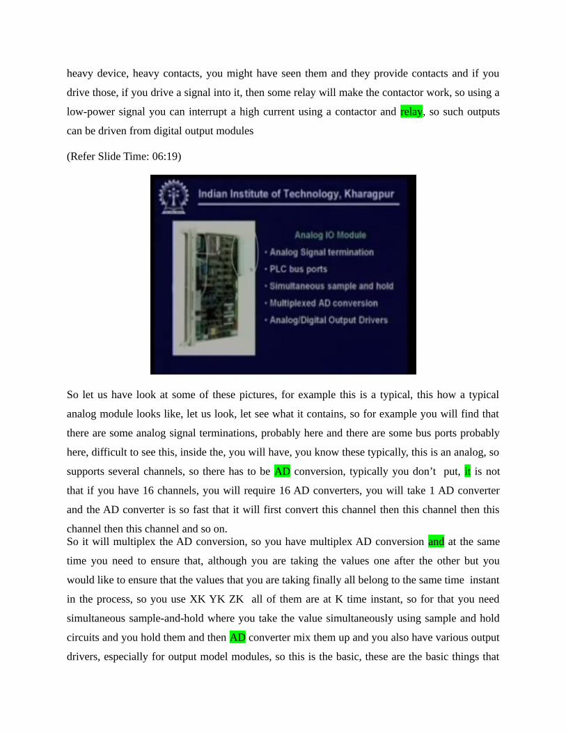
So let us have look at some of these pictures, for example this is a typical, this how a typical
analog module looks like, let us look, let see what it contains, so for example you will find that
there are some analog signal terminations, probably here and there are some bus ports probably
here, difficult to see this, inside the, you will have, you know these typically, this is an analog, so
supports several channels, so there has to be AD conversion, typically you don’t put, it is not
that if you have 16 channels, you will require 16 AD converters, you will take 1 AD converter
and the AD converter is so fast that it will first convert this channel then this channel then this
channel then this channel and so on.So it will multiplex the AD conversion, so you have multiplex AD conversion and at the same
time you need to ensure that, although you are taking the values one after the other but you
would like to ensure that the values that you are taking finally all belong to the same time instant
in the process, so you use XK YK ZK all of them are at K time instant, so for that you need
simultaneous sample-and-hold where you take the value simultaneously using sample and hold
circuits and you hold them and then AD converter mix them up and you also have various output
drivers, especially for output model modules, so this is the basic, these are the basic things that

analog i/o module will contain and of course some logic for synchronization then you have a
different kind of i/o modules which are called distributed or sometimes called remote i/o
modules.
(Refer Slide Time: 08:08)
So these are actually intelligent field mountable i/o devices, so you actually put the i/o module
right there on the machine and from there you draw a wire or you connect it to a network or you
take an input-output concentrator and connect several local distributed I/O’s and then make one
digital communication back to the PLC, the advantages are mainly in savings in cabling costs, I
might have mentioned before that cabling costs are non, not insignificant part of any industrial
automation project, so, and they actually cause inconveniences in industrial environment, they
are difficult to maintain, sometimes may get cart etc.
So savings in cable costs and maintenance costs are significant, then they are, they are
sometimes, especially when they are on the network they are actually programmable from a,
parameterizable from a processor or a programmer, they have, because they generally
communicate with the processor over, they first of all, they communicate with the processor
infrequently because they can, there, they are actually intelligent themselves and they can do
much of their work, secondly they often communicate with using digital communication
protocols which are much more reliable, so you have much improved data integrity, your cost of
cable etc comes down.

So typically used for applications like, you know very close positioning with analog digital
encoders which requires frequent sampling frequent slow output generation, very difficult to do
it with the central processor because it will get loaded, high speed counters which needs to count
high speed events like, you know fast-moving shaft, angle pulses, some specific loop controllers
temperature control loop etc where you just need to download the set points from the central
processor and the basic loop works on the distributor I/O module. So this main processor is not
bothered with that, so that is distributed I/O, generally getting more and more popular now, these
days.
(Refer Slide Time: 10:22)
Then you have some other kinds of modules called function modules, these are also, these are
not, sometimes they could also be mounted on the machine and make part of a distributed I/O but

otherwise they may be situated on the PLC rack itself but still they are actually independent
modules that can execute tasks independently, so basically reducing the center processor load, so
that it needs to talk to it less often, for precision and high-speed tasks and they often have their
own logic their own pre coded control laws, they have their own, you know optimizing abilities
it might tune its own way, you just have to give it a command that you tune yourself.
So it will, it has its own code it will actually tune a control loop and typical application would be
stepper servo control, multi-axis synchronization, as we have, we will see after just following
this, we will go into the manufacturing CNC machine control, so we will find that there are, there
are many cases where a precise two-dimensional motion has to be created, suppose we are, you
are actually cutting something along a surface, you have to create precise two-dimensional
motion, so you have to give motions along two axis motion commands and they have to be very
synchronized, so that is called multi-axis synchronization, for such applications typically you use
function modules, specialized function modules and sometimes there they could be also used
with distributed i/o systems to be situated on the machines themselves.(Refer Slide Time: 11:57)
This is a, this is another controller which is a valve control module, I chose this because I wanted
to show the power transistors on this, so you are, you can see the power transistors, so it has to
drive, valve means it can, it is probably a, probably a hydraulics servo valve or something or, so
it has to pull a solenoid create some force so that the piston moves, so for that it needs to provide
good amount of current, so you have the, these are the power transistor drives, it takes set point

from outside, so it interfaces to the bus and the central processor gives it the set point and it has
its own onboard controller right.
So this is a typical valve, this is another picture a counter module, you cannot make out much on
the picture except for the fact that you can see certain things, you know like for example, oops
we need to go back, so you see, you can see that for example this is the, this module content for
thing five counters, so you see the count value has to be read on the bus, so these have count
values have to be read then event signals that is go, up, up, up, this thing has to come, so there
are probably five counters here, on the other hand it also connects to the bus, so that these signals
can be read, generally used for, so this, so the count is readable on the fly because it contains
dual ported RAM and high-speed count.So general use for very high speed count, so one could, one would have large registers and things
like that.
(Refer Slide Time: 13:48)
This is, this is a counter position decoder, see a most counter modules can easily be used because
position decoding is often by counting the shaft angle pulses, shaft angle encoder pulses that are
coming over a certain period of time or every pulse will mean a certain small angle rotation, so if
you want to have shaft angle position decoder, it’s basically counting pulses, so I mean, some of
this, you know some of these can be used for, this can be used for either as a counter or as a
position decoder, so you have pulse inputs, you can count or you can read shaft position and
both, they will be readable on the fly as we said and for high speed. So this is just, you know
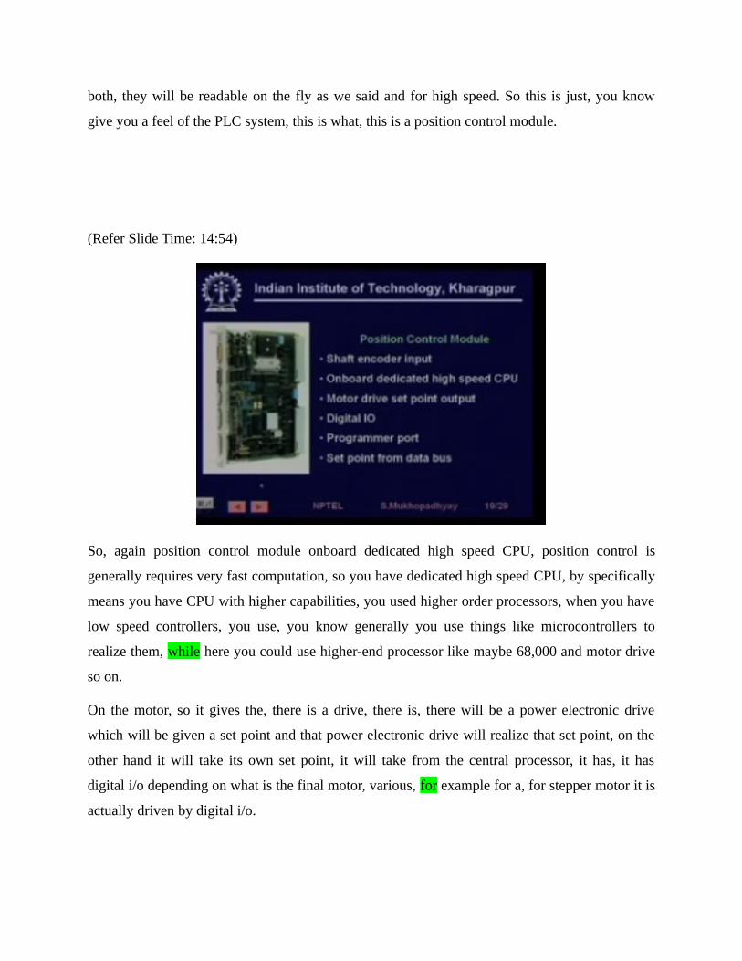
give you a feel of the PLC system, this is what, this is a position control module.
(Refer Slide Time: 14:54)
So, again position control module onboard dedicated high speed CPU, position control is
generally requires very fast computation, so you have dedicated high speed CPU, by specifically
means you have CPU with higher capabilities, you used higher order processors, when you have
low speed controllers, you use, you know generally you use things like microcontrollers to
realize them, while here you could use higher-end processor like maybe 68,000 and motor drive
so on.
On the motor, so it gives the, there is a drive, there is, there will be a power electronic drive
which will be given a set point and that power electronic drive will realize that set point, on the
other hand it will take its own set point, it will take from the central processor, it has, it has
digital i/o depending on what is the final motor, various, for example for a, for stepper motor it is
actually driven by digital i/o.

So these are some of these modules which are used in PLC systems, it has a programmer port
because you need to, there are, there are large number of parameters which have to be set and set
point comes from the data bus.
(Refer Slide Time: 16:30)
So all these modules how they are connected, that is what are the various data paths, to
understand this you have to understand that the PLC, I am sorry, this, so the PLC is, as we say,
we have said that is, that it is rack mounted right. So there are a number of racks, it is like an
Almirah, there are a number of racks, in each rack there are slots, so in each slot you can put i/o
modules or you can put CPU modules and in each slot, so this is slot, this is rack, and in each slot
contains several channels right, so there could be eight analog channel, so channels, so this is
how I/0 is actually organized, it is rack slot channel.
So if you want to identify a particular physical signal, you have to, this is, you have to have a
rack slot channel addressing, which is implemented in various ways by various manufacturers,
now all these racks must be connected, so these, they are actually connected at this level by
ribbon cables and then from rack to Rack connection is generally achieved, okay, we will see this
is the next diagram.
(Refer Slide Time: 17:53)

So here you are, so these are, you know this is one rack let us say, this is one rack then you can
have several racks, for example, so they are actually connected by what are known as interface
units, so these are interface modules, similarly, so you can expand your number of modules,
sometimes you can put, as i was telling that, you can put your modules in a different Almirah
which is different cabinet, let's say almirah actually is a cabinet, so for that you need to have a
special, you know special interface unit.
So typically your interface unit will, it can be say typically such distance, for reliable data
transmission such distance requirements are there at a certain rate, so you can go up to
something like an 100 meters which is a lot and sometimes you can have remote interfacing that
is actually, you have, you may be having your CPU in some, that is your basic PLC system in
some control room while you have these various interface units in the various shop floats, which
could be even you know half a kilometer away and things like that.
So in such cases, you need special interface units which are called remote interface units, so this
is the way that all these elements are actually connected with each other and buses are extended.
(Refer Slide Time: 19:44)
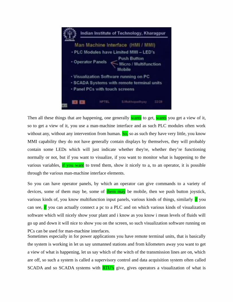
Then all these things that are happening, one generally wants to get, wants you get a view of it,
so to get a view of it, you use a man-machine interface and as such PLC modules often work
without any, without any intervention from human. So, so as such they have very little, you know
MMI capability they do not have generally contain displays by themselves, they will probably
contain some LEDs which will just indicate whether they're, whether they’re functioning
normally or not, but if you want to visualize, if you want to monitor what is happening to the
various variables, if you want to trend them, show it nicely to a, to an operator, it is possible
through the various man-machine interface elements.
So you can have operator panels, by which an operator can give commands to a variety of
devices, some of them may be, some of them may be mobile, then we push button joystick,
various kinds of, you know multifunction input panels, various kinds of things, similarly if you
can see, if you can actually connect a pc to a PLC and on which various kinds of visualization
software which will nicely show your plant and i know as you know i mean levels of fluids will
go up and down it will nice to show you on the screen, so such visualization software running on
PCs can be used for man-machine interfaces.Sometimes especially in for power applications you have remote terminal units, that is basically
the system is working in let us say unmanned stations and from kilometers away you want to get
a view of what is happening, let us say which of the witch of the transmission lines are on, which
are off, so such a system is called a supervisory control and data acquisition system often called
SCADA and so SCADA systems with RTU’s give, gives operators a visualization of what is
happening quite far away in unmanned places, there also MMI, they also have MMI purpose
Sometimes you have panel pcs, they are special types of pcs with you know touch screen.
So that the operator you know did not type, he can just, for basically convenience because an
operator has to concentrate on the process and should not be bogged down with, you know, it
should be as easy for him to give commands as possible, so people use you know devices like
touch screens in such environments.
(Refer Slide Time: 22:04)
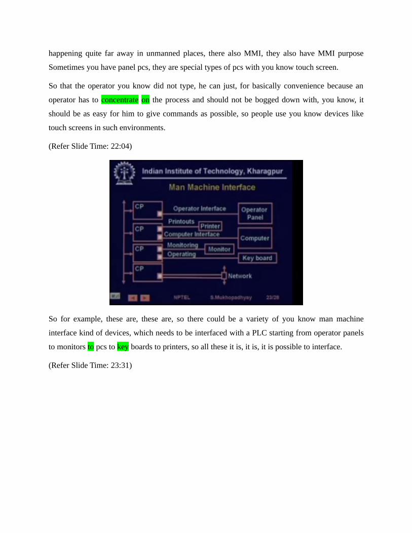
So for example, these are, these are, so there could be a variety of you know man machine
interface kind of devices, which needs to be interfaced with a PLC starting from operator panels
to monitors to pcs to key boards to printers, so all these it is, it is, it is possible to interface.
(Refer Slide Time: 23:31)
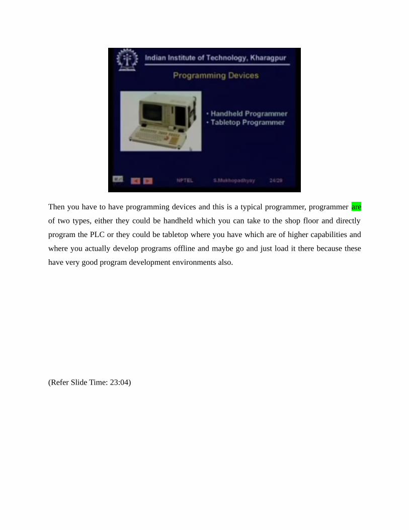
Then you have to have programming devices and this is a typical programmer, programmer are
of two types, either they could be handheld which you can take to the shop floor and directly
program the PLC or they could be tabletop where you have which are of higher capabilities and
where you actually develop programs offline and maybe go and just load it there because these
have very good program development environments also.
(Refer Slide Time: 23:04)

Finally another very important thing is communication, so there are various types of
communications available as you have already told, for example point to point where you run
direct wires from an, from an input or output module to the actual device, they could be, bus
communication is actually internal to the, to the modules or you could be network
communications, where network or remote, this we have already explained, communication
technology could be, communication medium can be various, for example it can be radio, it can
be coaxial channels, it can be fiber optic cables.
So different physical media maybe supported, are supported, various protocols are supported, for
example RS-232 / 4 to 20 milli ampere current loop, RS 422 / 485, these are, these are point-to-
point communication protocols, apart from that there could be network protocols, for example
industrial Ethernet are sometimes used, where the computational requirements are well known,
well understood and you know that due to, that is CSMA/CD media access protocol you are not
going to get performances is not going to degrade, you have a fieldbus that’s a, that’s a new
standard for networking in the industrial environment which we shall be studying it much more
detail.There are other less popular probably, I can call them less popular, for example the can bus, the
can bus is much more popular in in another application environment that automobiles, field
buses gaining popularity in the industrial environment and some buses could be, you know
proprietary, for example siemens has a bus called scenic which is proprietary protocol bus.
(Refer Slide Time: 24:57)

The advantages of distributed Network i/o are well understood, cost saving on maintaining
integrity of high-speed signals because digital come, basically the advantages of digital
communication and the advantages of having an intelligent module near the machine, so you can
have good sensor Diagnostics fault, fault can be much more, you know monitoring functions can
be realized without overloading CPU, you can do special function like startup, so in a sense in
such cases the PLC CPU really works like a supervisory system and the actual controls system
on the spot.
(Refer Slide Time: 25:33)
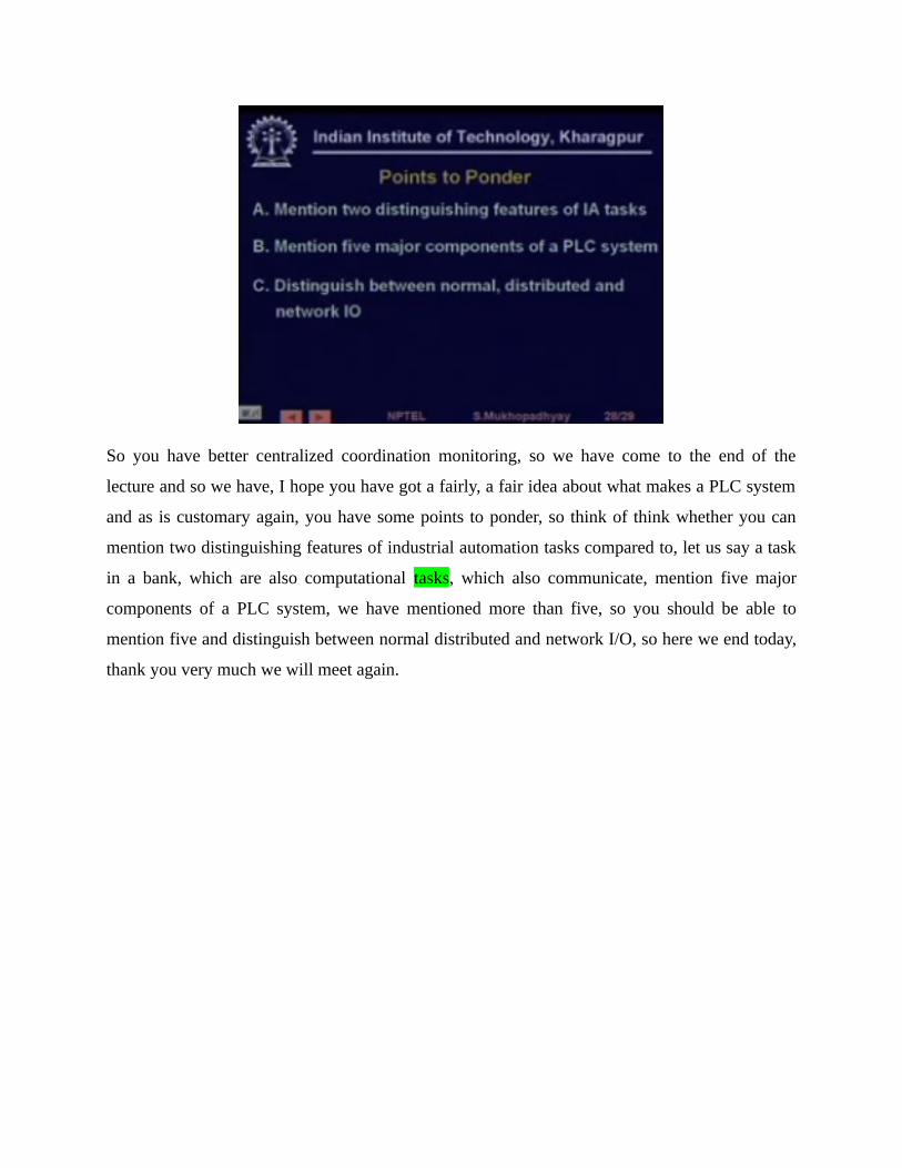
So you have better centralized coordination monitoring, so we have come to the end of the
lecture and so we have, I hope you have got a fairly, a fair idea about what makes a PLC system
and as is customary again, you have some points to ponder, so think of think whether you can
mention two distinguishing features of industrial automation tasks compared to, let us say a task
in a bank, which are also computational tasks, which also communicate, mention five major
components of a PLC system, we have mentioned more than five, so you should be able to
mention five and distinguish between normal distributed and network I/O, so here we end today,
thank you very much we will meet again.