Embed Size (px)
Citation preview

50
th
IG
C
50th
INDIAN GEOTECHNICAL CONFERENCE
17th
– 19th
DECEMBER 2015, Pune, Maharashtra, India
Venue: College of Engineering (Estd. 1854), Pune, India
BEHAVIOR OF SHALLOW FOUNDATION UNDER DYNAMIC LOAD
PRITAM DHAR1, DR. BIKASH CHANDRA CHATTAPADHY
2,
ABSTRACT
Most in many cases final portion of path of the earthquake waves passes through soils and properties of
these soils greatly influencece the nature of shaking at the ground surface. As soil conditions vary widely
over short distance both horizontally and vertically. Modifications of the resulting shakings will be large
even over a small area. The resulting ground shaking at any site is prime cause of all hazards due to
earthquake at the site. To study the effect of an devastating earthquakes great lessons can be obtained
from examining the resulting hazards occurred due to various earthquake. Excellent reports on hazards
occurring due to several earthquakes which visited India over last five decades are available. A recently a
devastating earthquake visited Nepal in April 2015 causing human death over eight thousand and huge
loss of property in that country and also some losses in adjoining zones in India and China. From review
of damages from such earthquake causes for failure of structures and damages can be grouped in four
divisions namely
(i) Structural deficiencies and use of improper construction and materials.
(ii) Ground movement,
(iii) Liquefaction in supporting medium ,
(iv) Loss of strength of resting material under dynamic condition loading is decreased in
supporting power to the constructed structures.
Out of the four major major factor listed above the last one is considered in detail in this paper
During earthquakes the foundations are subjected to dynamic forces which are generally assumed
to be horizontal, while during nuclear blasts the forces are taken to be acting vertically. Due to occurrence
of an earthquake at a location there is possibility of liquefaction in soil at some depth below ground level,
causing tilting, sinking or destruction of the structure. But when liquefaction does not occur, there is
possibility of decrease of bearing power of the foundation to unknown degree causing distress of the
foundation. In such cases the loss of bearing, need to be investigated and taken into consideration to safe
guard the safety of the foundation under possible earthquake at the location. The earthquake forces along
with the static forces over the foundation constitute the force system on the foundation. There are simple
approaches to analysis the condition, which are basically pseudo static. For considering the earthquake
effects India has been divided into four zones for estimating causable seismic forces shown in figure
below.
1Dhar_ Pritam1, Civil Engineering, SDET Brainware Group of Institutions, Barasat, India, [email protected]
2Chattpadhyay_ Bikash.Chandra2, Civil Engineering, Ex Head of Bengal Engineering and Scince University, Kolkata, India,
Pritam Dhar, Dr.Bikash Chandra Chattapadhyay
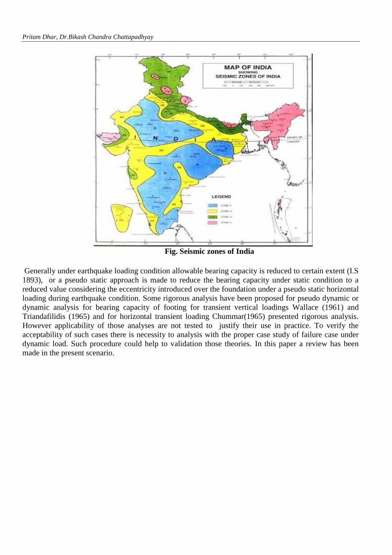
Fig. Seismic zones of India
Generally under earthquake loading condition allowable bearing capacity is reduced to certain extent (I.S
1893), or a pseudo static approach is made to reduce the bearing capacity under static condition to a
reduced value considering the eccentricity introduced over the foundation under a pseudo static horizontal
loading during earthquake condition. Some rigorous analysis have been proposed for pseudo dynamic or
dynamic analysis for bearing capacity of footing for transient vertical loadings Wallace (1961) and
Triandafilidis (1965) and for horizontal transient loading Chummar(1965) presented rigorous analysis.
However applicability of those analyses are not tested to justify their use in practice. To verify the
acceptability of such cases there is necessity to analysis with the proper case study of failure case under
dynamic load. Such procedure could help to validation those theories. In this paper a review has been
made in the present scenario.
50
th
IG
C
50th
INDIAN GEOTECHNICAL CONFERENCE
17th
– 19th
DECEMBER 2015, Pune, Maharashtra, India
Venue: College of Engineering (Estd. 1854), Pune, India
BEHAVIOR OF SHALLOW FOUNDATION UNDER DYNAMIC LOAD
Pritam Dhar, Assistant Professor, CE Department, SDET Brainware Group of Institutions,. [email protected].
Dr. Bikash Chandra Chattapadhyay, Ex H.O.D & Ex Head, CE Department, Bengal Engineering & Scince
University,Sibpur [email protected]
ABSTRACT: The earthquake forces along with the static forces over the foundation constitute the force system
on the foundation. There are simple approaches to analysis the condition, which are basically pseudo static.
Generally under earthquake loading condition allowable bearing capacity is reduced to certain extent (I.S 1893) or
a pseudo static approach is made to reduce the bearing capacity under static condition to a reduced value
considering the eccentricity introduced over the foundation under a pseudo static horizontal loading during
earthquake condition. Some rigorous analysis have been proposed for pseudo dynamic or dynamic analysis for
bearing capacity of footing for transient vertical loadings Wallace (1961) and Triandafilidis (1965) and for
horizontal transient loading Chummar(1965) presented rigorous analysis. However applicability of those analyses
are not made to justify their use in practice. To verify the acceptability of such cases there is necessity to analysis
with the proper case study of failure case under dynamic load. Such procedure could help to validation those
theories.
In this paper a review has been made in the present scenario.
INTRODUCTION
Due to earthquake natural hazards may occur
causing deaths, injuries, property damages, change
of topography and destruction of immense
magnitude. During earthquake, earthquake waves
radiate from the source and travel through earth’s
crust. As the waves reach the ground, they produce
shaking, lasting over few seconds to minutes. Even
sometimes seismic waves may come as successive
shocks occurring during several months as in
Crimean Earthquake in 1927. A typical example
was seen in 1966, when during Tashkant
Earthquake, waves appeared over a year almost
uninterrupted. The resultant shakings are
dependent on the size of the earthquake, location of
the site with respect to focus of the earthquake,
characteristics of materials along the path of travel
of the earthquake waves and local site conditions.
The resulting ground shaking produced at the site,
is the prime cause of all hazards caused at the site.
In many cases the final portion of the path of
earthquake waves from its origin, lies through soils
and characteristics of these soils greatly influence
the nature of shaking at the ground surface. As soil
conditions vary widely over short distance in space
, the effect of soils on modifying the resulting
shaking is also widely varying , even over a small
area. The soil deposits tend to act as a filter to
seismic waves by attenuating motion at certain
frequencies and amplifying them at others.
It will be of great interest to summarise effects of
last few devastating earthquake which had visited
India in recent few decades at different parts of the
country.
BRIEF REVIEW ON HAZARDS FROM
RECENT EARTHQUAKES
Indian Concrete journal has recently brought out a
very informative compilation of the different
aspects of recent earthquakes in the country
reported by distinguished earthquake specialists,
Brief review of such observations are made below.

Pritam Dhar, Dr.Bikash Chandra Chattapadhyay
Koyna Earthquake (1967): In 11th
December,
1967, a strong earthquake with the epicentre close
to Koyana Hydro-electrical project, shook the
western coast of India and the whole of
Maharashtra state. The effect of the earthquake on
the area were reported by Chandrasekhar, Srivastav
and Arya (2004) [1].
Bihar Earthquake (1988): A moderate earthquake
had rocked at Bihar-Nepal border region on August
21, 1988, causing damages in areas around northen
part of Bihar and south-eastern part of Nepal.
Thakkar (2004) verified critically these damages
due to this earthquake [2].
Uttarkashi Earthquake(1991): On October 20,
1991, an earthquake struck the Garhwal Himalayas
in northern India near Uttarkashi, causing wide
spread devastation and loss of life. Paul (2004)
reported the lessons learnt from this earthquake [3].
The observations of structural performance of
building during earthquakes provide volumes of
information’s about the merit and demerits of the
design and construction practice in a region since it
is based on the actual test on the prototype
structures.
Poor quality of workmanship, ignorance of
earthquake engineering practice, inadequacies of
road construction leading to instability of hill
slopes are identified as some of cause adding
severity of the damages.
Killari Earthquake (1993): Decan traps of
peninsular India was generally thought to be
seismically stable. But a devastating earthquake
struck south central India in September 30, 1993.
The epicentre was near village Killari in Latur
district in Maharasthra. Sinha and Murthy (2004)
reported engineering lessons from this earthquake
[4].
Bhuj Earthquake (2001): A devastating
earthquake visited the Kutch area in Gujrath on
26th
January 2001, causing more than 18000
human death and huge property loss. Salient
structures and geotechnical damages of this
earthquake had been reported by Murty et.al.
(2004) [5].
The earthquake caused excellent examples of large
scale liquefaction and embankment failure. The
Great Runn Kutch , The Arabian Sea and the Little
Runn of Kutch lock the affected area on three
sides. The enclosed area at near sea level sustained
extensive liquefaction. At least five earth dams
failed during earthquake. The earthen
embankments of the rail road and highway also
suffered widespread damage.
Nepal Earthquake (2015): Aydan and Ulusay
(2015) presented a quick report on the devastation
earthquake that has visited Nepal on 25th
april 2015
[6]. Some of the salient features of the damager are
detailed below.
a) Mass Movement: The epicentral area is
very mountainous and valleys are steep and
laid sedimentary rocks are heavily folded
and faulted resulting from the tectonic
movements and subjected to weathering
due to intense freezing thawing cycles as
well as water content variations. The mass
movements are quite similar to those
observed recently in the 2005 Kashmir and
2008 Wanehuan earthquakes.
b) Liquefaction induced ground failure:
Although detailed information on the
occurrence of liquefaction during this
earthquake has not been reported yet, some
picture from Kathmandu clearly confirmed
that liquefaction did occur in Kathmandu.
In addition, ground liquefaction did occur
in even Bihar region of India.
c) Roadway Damage: The roadway
embankments in Kathmandu city suffered
some damage in from of subsidence and
lateral spreading. Improper compaction,
lateral spreading of sidewalls and
subsidence of saturated soil beneath the
embankments would be the potential cause
as expected from various geotechnical
investigation in Kathmandu.
d) Damage to Bridges: There is no report yet
about the damage to bridges. Bridge in
Gorkha district is a single-span truss bridge.

50
th
IG
C
50th
INDIAN GEOTECHNICAL CONFERENCE
17th
– 19th
DECEMBER 2015, Pune, Maharashtra, India
Venue: College of Engineering (Estd. 1854), Pune, India
This bridge is also not damaged despite it
was located in the epicentral area.
e) Utility Poles: Some reinforced concrete
utility poles having rectangular cross
section were toppled down during
earthquake shaking. Some corossion of
reinforced bars was noticed in the poles
collapsed due to shaking.
f) Damages to dams: Nepal has been trying
to improve the energy storage by building
dams along major rivers. There is no report
of damage by the earthquake at other
hydropower dam sites.
g) Structural Damages:
a) Building Damage: The shallow depth
of the focus and the nature of
Kathmandu valley have contributed to
the high losses in the capital of Nepal.
However, it should be noted that the
quality of construction and materials of
building is very poor. Many recently
built reinforced concrete structures
failed in a pan-cake mode due to
improper column-beam connections.
Furthermore, many brick structures
collapsed or heavily damaged due to the
use of poor mortar material and tie
beams and slabs within the walls. The
wall of houses were built as dry
masonry and their resistance are mainly
due to frictional forces. In addition
plastic deformation of their foundation
on slopping ground shaking was a
another cause of collapse and heavy
damages. Although Nepal has been
trying to improve its safety and
infrastructure by updating building
codes for more than two decades the
efforts were not sufficient.
b) Damage to Monuments: Historical
monuments as well as religious
structures associated with Buddhism
suffered tremendous damage induced
by this earthquake. Most of the
structures are of masonry type using
brick and earth-mortar as a bonding
agents.
IMPORTANT LESSONS:
In general it could be surmised that at any location
major disasters due to earthquake depend on the
magnitude of the earthquake, site condition, focal
distance of the site and depth of the focus,
frequency of earthquake at the site and
concentration of population and property at the
region. From the review made on the damages
caused by several major earthquake which had
visited in recent few decades in different parts of
Indian sub continent , causal mode of damages and
failures due to earthquake may be associated with
(i) Structural deficiencies and use of
improper construction and materials
(ii) Ground movement
(iii) Liquefaction in supporting medium
(iv) Loss of strength of resting material
under dynamic condition loading is
decrease in supporting power to the
constructioned structures
Out of the above four major factors the last one is
considered in detail in this paper.
Due to earthquake at many cases it has been
observed, that isolated footing, raft foundation and
even pile foundations have failed , causing failure
of the structure. Even relatively low loaded
structures like pavement, rail road etc have been
seen to be totally dislocated due to earthquakes.
Such failure have generally been reasoned due to
liquefaction of soil under at some depth, due to
presence of water to saturated the void spaces in
soils in the layers and reducing effective stress to
zero under earthquake condition. However failure
have occurred where there is only partial saturation
or complete unsaturation, even in dense soils
(Rechards et.al. 1993). Such failure was observed
in Miyagihel-Oki earthquake of magnitude 7.8 in
1978 due to earthquake where soil was dry and
dense enough to avoid liquefaction. (Shafiee and
Jahanandish 2010) [7]. Such phenomenon is
refered as “Seismic Shear fluidization” and in such
case soil flows at finite levels of effective stress
Pritam Dhar, Dr.Bikash Chandra Chattapadhyay
and it can take place in dry soil in which no pore
water pressure is present(Rechards Etal 1990)[8].
During dynamic situation properties of soils get
modified and assume values largely different and
lesser the from those under static condition
(Barkan 1962). Thus during earthquake condition
load carrying capacity of soil is modified and may
get decreased to a significant amount. Thus seismic
bearing capacity of footing has become one of the
most interesting topics of research and also of
practical need at present days.
DYNAMIC BEARING CAPACITY UNDER
EARTHQUAKE CONDITION
During earthquake the engineering property of soil
, supporting the foundation, gets modified to
varying degree , depending on the site condition ,
magnitude of earthquake, ground water table
condition, types of soils etc. Under such condition
foundations are maybe subjected to dynamic form
which are generally assumed to be horizontal.
Suddenly approximate value of the seismic
coefficients, equivalent seismic forms are
evaluated. Bearing capacity of shallow foundation
can be estimated by three types of approaches,
those are
(a) Pseudo-static analysis
(b) Pseudo-Dynamic analysis
(c) Dynamic analysis
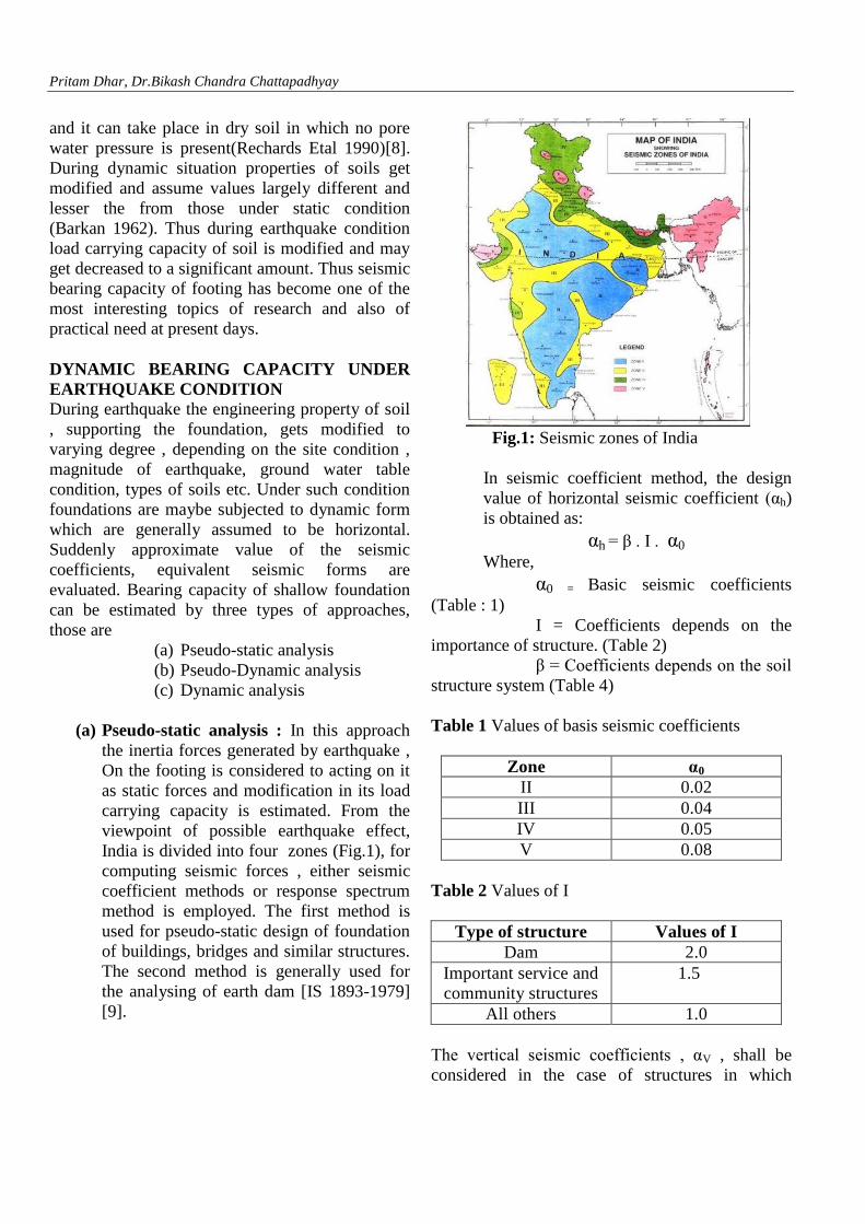
(a) Pseudo-static analysis : In this approach
the inertia forces generated by earthquake ,
On the footing is considered to acting on it
as static forces and modification in its load
carrying capacity is estimated. From the
viewpoint of possible earthquake effect,
India is divided into four zones (Fig.1), for
computing seismic forces , either seismic
coefficient methods or response spectrum
method is employed. The first method is
used for pseudo-static design of foundation
of buildings, bridges and similar structures.
The second method is generally used for
the analysing of earth dam [IS 1893-1979]
[9].
Fig.1: Seismic zones of India
In seismic coefficient method, the design
value of horizontal seismic coefficient (αh)
is obtained as:
αh = β . I . α0
Where,
α0 = Basic seismic coefficients
(Table : 1)
I = Coefficients depends on the
importance of structure. (Table 2)
β = Coefficients depends on the soil
structure system (Table 4)
Table 1 Values of basis seismic coefficients
Zone α0
II 0.02
III 0.04
IV 0.05
V 0.08
Table 2 Values of I
Type of structure Values of I
Dam 2.0
Important service and
community structures
1.5
All others 1.0
The vertical seismic coefficients , αV , shall be
considered in the case of structures in which

50
th
IG
C
50th
INDIAN GEOTECHNICAL CONFERENCE
17th
– 19th
DECEMBER 2015, Pune, Maharashtra, India
Venue: College of Engineering (Estd. 1854), Pune, India
stability in a criteria of design or for overall
stability of structures. It is generally taking as half
the value of horizontal seismic coefficient.
In response spectrum method, the response
acceleration coefficient is first determine from the
natural period and damping of the structure and the
design value of horizontal seismic coefficient αh is
computed from the expression below
αh = β I F0
Where,
F0 = Seismic zoning factor for average
accurating spectrum (Table 3)
= Avarage accuration coefficients as
read from Fig.2 for appropriate natural period and
damping of structures.
These forces along which static forces are
considered to be acting on the foundation as if in
static condition and solution for bearing capacity is
considered for the foundation subjected to resulting
load with becomes eccentric and inclined.
Fig 2. Response spectra for rock and soil sites for 5
% damping.
In pseudo-static analysis bearing capacity of
foundation adopting suitable value of horizontal
and vertical seismic coefficients at a site equivalent
seismic forces are evaluated .
Table 3 Values of Seismic Zoning factor , F0
Zone F0
II 0.10
III 0.20
IV 0.25
V 0.40
Effect of Eccentric inclined load:
If the resultant load on the foundation has an
eccentricity , e, only in one direction then the
dimension of the foundation in that direction is
allowed to be reduced bt 2e the modified
dimension shall be used in conventional generally
bearing capacity equation used the static cases. If
the load has double eccentricity eL and eB with
respect to centroied of the footing , the effective
dimension of the footing , L’ x B’ , in resisting the
load shall be determine has L’= L-2eL and B’ = B-
2eB Where L and B are original dimension.
In computing shape and depth factor for
eccentrically inclined loaded footings effective
length and bredth as calculated above shall be used
however eccentricity in any direction shall be
limited to 1/6 of the corresponding of the
foundation direction as per IS 6403 [10] the
inclination factor are given by ic= iq = [1-i/90]2
iy
= [1- i/fi]2
For more accurate determination of an
eccentrically or obliqulay loaded footing some
significant works are reported in last few decades
(Purakayastha & Char 1977 [11], Saran & Agarwal
1990) [12].

Pritam Dhar, Dr.Bikash Chandra Chattapadhyay
Table 4 Value of β for different soil foundation
support
Soil
β
Isolated footing
with
out tie
beam
Combi
ned isolated
footing
with
tie
beam
Ra
ft
Ra
ft
Pile
founda
tion
Well
found
ation
Roc
k or
hard
soil
1.0 1.0 1.0 1.0 1.0
Med
ium
Soil
1.2 1.0 1.0 1.0 1.2
Soft
Soil
1.5 1.2 1.0 1.2 1.5
Purakayastha and Char (1977) conducted
stability analysis of eccentrically loaded strip
foundations (α = 0) supported by granular soil
using method of slices proposed by Janbu (1957).
Based on their study it was proposed that, for a
given Df / B
( )
( ) =R = (
)
Where,
quv(e,α=0) = Avarage ultimate vertical load
per unit area of the foundation with load
eccentricity e and load inclination α = 0
quv(e =0,α = 0) = Avarage ultimate bearing
capacity with centric vertical load
R= reduction factor
C= Df /B only and independent soil
frictional angle φ. The variation of b and c with Df
/ B is given in table
Table 5 Variation of B and C with Df/B –Analysis
of purakayastha and char
Df/B b c
0 1.862 0.73
0.25 1.811 0.785
0.5 1.754 0.80
1.0 1.820 0.888
For Df/B between zero and 1 the average value of b
and c are about 1.81 and 0.8 respectively. So the
equation can be approximated as
( )
( ) = R = (
)
Saran and Agarwal (1991) reported an
equilibrium analysis to evaluate the ultimate
bearing capacity of strip footing subjected to
eccentrically inclined load. According to their for
foundation on granular soil
(
)
(
)
(
)
Where,
(
)
Avarage inclined load per unit
area with load eccentricity ration
and inclination
α.
(
) (
) Bearing capacity factors
expressed in terms of load eccentrically e and
inclined at an angle α to the vertical. Details of the
above factors are presented elsewhere.
Richard et.al. (1993) presented an analytical
solution for bearing capacity of strip footing of
width B, placed at a depth Df below existing
horizontal ground level (Df < B), with inertial
forces in soil and footing, using a Coulomb’s type
mechanism [13]. Using the simplification of
eliminating the fan shaped transition zone in
conventional Prandtl’s failure mechanism, and
there by averaging its effect concentrating the
shear strength on imaginary vertical wall through
one of the extremities of the footing (Fig. 3),

50
th
IG
C
50th
INDIAN GEOTECHNICAL CONFERENCE
17th
– 19th
DECEMBER 2015, Pune, Maharashtra, India
Venue: College of Engineering (Estd. 1854), Pune, India
bearing capacity factors for each component of
strength were derived and they presented the
ultimate bearing capacity in earthquake situation as
Where, NCE, NqE and NγE are bearing capacity
factors during earthquake, similar to those in Static
condition. But these factors are dependent on the
angle of shearing resistance of soil, φ, and also
magnitude of the developed values of acceleration
during earthquake.
The active – passive Coulomb’s Wedge
mechanism, adopted by them, allowed adoption of
sliding block approach to calculate seismic
displacement of the footing. Though the
mechanism is not exact, it helps to estimate the
seismic bearing capacity factors. Authors
suggested that the values of seismic bearing
capacity factors and computed settlements are both
conservative.
The model directly allows the formulation of the
seismic bearing capacity factors to compare with
their counterparts in static conditions and at the
same time the model is capable of depicting the
pattern of the change in the surfaces with change of
the values of acceleration to explain the shear flow
and settlement occurring during earthquake.
Fig 3. Simplified static slip field (After Rechards
et.al. 1993)
Sarma and Iossifelis (1990) analysed the similar
problem by using a techniques for slope stability
based on a method of inclined slices [14].
Shafiee and Jahanandish (2010) presented a
finite element method was used to estimate the
seismic bearing capacity of strip footing for wide
ranges of value of angle of shearing resistance, and
seismic coefficients [15]. Using the pseudo-static
approach, seismic forces are considered as the
horizontal loads applied to the foundation,
surcharge at the underlying soil. Plain straw
elastic-plastic Mohr- Coulomb model encoded in
PLAXIS was used. Solution for the bearing
capacity factors are presented for different values
of horizontal acceleration and angle of shearing
resistance. With the increase in the value of earth
quake acceleration all the bearing capacity factors
decreases for any value of the angle of shearing
resistance further the analysis conclusively
indicated that soil inertia plays a negligible
compared to structural seismic loads
PSEUDO – DYNAMIC APPROACH
Pseudo-dynamic approach for finding seismic
bearing capacity of strip footing on uniform
cohesion less soil has been recently presented by
Ghosh and Choudhury (2011) [16], Considering
effect of both shear and primary waves, soil
amplification, duration and period of lateral
shaking. Similar failure wedges as proposed by
Richards et.al. (1993) are considered with linear
variations for horizontal and vertical seismic
acceleration with input acceleration at the base of
the failure wedges to the higher value at the level
of footings. Active and passive earth pressure
behind the imaginery vertical wall between the
active and passive wedge proposed by Richards
et.al. (1993) and pseudo dynamic approach had
earlier been presented by Chowdhury & Nimbalkar
(2006, 2008) [17].
DYNAMIC ANALYSIS
The bearing capacity of foundations under dynamic
condition started drawing attention of investigators
in geotechnical engineering from early 1960. The

Pritam Dhar, Dr.Bikash Chandra Chattapadhyay
attempted analyses have been developed on certain
simplifying assumptions. In general three different
approaches are made. In one of them it has been
assumed that during failure under dynamic
condition similar failure surface develops as under
static condition. The equation of motion is then
developed from the equilibrium conditions. In the
second method wave propagation theory is utilized.
The equation of wave motion resulting from
dynamic loads gives the surface displacement. In
the third approach the footing response is
considered as the presence of single degree of
freedom mass-spring-dash pot model.
Wallace [1961], Triandafilidis [1961,1965] and
Chummar [1965] have analysed the problem by the
first method. Selig [1959] and Carroll [1963] have
analysed the problem by second method. Fisher
[1962] and Landate [1954] have analysed the same
by third method.
Wallace [1961] analysed the dynamic bearing
capacity of long footing considering the failure
surface described by Terzaghi [1943] for static
loading for long footing with rough base. The
foundation medium was taken as C- φ soil [18].
The assumptions are
[i] The soils behaves like rigid –plastic
material.
[ii] The soil mass with in failure surface
acts as rigid body.
[iii] The critical spiral surface under static
condition will be also critical under dynamic
condition
[iv] The footings fails by punching in the
soil without any rotation
[v] Dynamic load on the footing is
triangular pulse.
[vi] Footing is weightless and imparts
uniform pressure on the soil.
The equation of motion was derived as
+ k∆ =
–
x t
Where,
∆ = Vertical displacement of the footing
k =
NR = Coefficient representing dynamic
shear resistance due to gravity restoring forces
N1 = Coefficient representing inertial shear
resistance
B = Width of footing
q = Peak value of dynamic pulse
[triangular]
qu = Static load on unit width of footing
td = maximum duration of pulse
For , t, from zero to td loading function = qB[1-
]
And for t greater than td loading function =0
The solution of the above equation yields the
footing displacement versus time relation. The
form of solution with boundary conditions being
satisfied, is
For t between zero to td
(
) (
)( )
( )
For t greater than td
[(
)
( )]
[
( )]
Where
Maximum displacement from above equations is
the permanent footing displacement, the value for
which can be obtained from above equations and is
available in graphical form [ Wallace (1961)]
Triandafilids [1965] presented a solution for
dynamic response of a continuous footing on a
saturated cohesive soil under vertical transient load
with several similar assumptions [19]. He assumed
that due to vertical dynamic load footing fails by
rotation about the base corner. The failure surface
is semi-circular with radius equal to width of
footing. For a transient vertical loading qd = qoe-βt
.
Wher overload factor λ = q0/qu (qu = Static bearing
capacity ) he developed the following equation by
balancing the moments of driving and resulting
forces,

50
th
IG
C
50th
INDIAN GEOTECHNICAL CONFERENCE
17th
– 19th
DECEMBER 2015, Pune, Maharashtra, India
Venue: College of Engineering (Estd. 1854), Pune, India
[
]
The natural frequency and time period of the
system are
Wn = √
& T =
The above equation is solved for maximum angular
deflection θ and charts have been developed for
various values of overload ratio λ for different
decay factor to give the dynamic load factor K,
where K is given by = (W/ 0.68g.qu) . θmax .
Chummar [1965] presented a solution for
dynamic response of a strip footing supported by
C-φ soil and subjected to horizontal transient load
[20]. However the above solutions are based on
several simplistic assumptions and validity of such
solutions are not yet verified for general
acceptance.
Lansdale [1954] had worked on the problem
considering the footing response to a transient load
as the response of single degree of freedom mass
spring dash-pot-model system [21]. He has
considered the mass which linearly increase as a
function of footing displacement. The initial mass
is that of the soil contained in a hemisphere with a
diameter 1.5 times the footing with the final mass
is that of the soil contained in static failure surface,
comparable to that assumed by Terzaghi’s long
footing. Fisher [1962] also worked in similar
manner for square footing placed on purely
cohesive or purely frictional soil. The responding
soil mass is considered to be of primordial shape,
the volume depending on the width of the footing.
He developed equation to give the settlement of the
footing under dynamic load and modified that to
correlate with experimental results.
CONCLUSIONS
From the view point of mitigation of seismic
hazards to safeguard possible damages caused due
to distress of foundation for earthquake effects,
need for estimate of safe bearing capacity of
foundation under earthquake loading are assuming
increasing importance both for researchers and
practising engineers. A brief review of the damages
caused due to earthquake in recent decades in India
has been made to indicate type of disasters caused.
Apart from the major failures due to lack of proper
earthquake resistant design of structure, use of
materials of adequate quality, ground movement
and liquefaction of soil at the location, it seems
partial loss of bearing capacity of footings has also
contributed to great extend for differential
movement at the base of constructed structures,
located over foundation medium having little or no
water content. It is to be noted that to estimate
allowable bearing capacity for design conventional
factor of safety used ranges from 2 to 3 over
ultimate bearing capacity. Hence decrease in
ultimate bearing capacity by even 100% during
seismic condition may not cause shear failure in
the supporting soils but generated deformation
particularly differential settlement, may be
excessive to cause great concern.
Different methods available in literature have been
discussed in the paper. Though numerical methods
are now extensively used in solving various
geotechnical problem but seismic bearing capacity
problem has hardly been attempted. Recently a
result of a numerical study based on pseudo-static
method of Richards et.al. has been presented (
Shafiee and Jahanandish [2010]). The study
indicates that effect of the pseudo-static force
applying to the soil mass, called soil inertia, has
very little effect on the result of seismic bearing
capacity. However there are little reported results
of experimental studies on the topic which would
be used to check the validity of methods discussed
in presented study. Thus comprehensive testing
programme is necessary to verify the validity of
assumptions made in different approaches and
identify the reasonable methodology for estimate
of dynamic bearing capacity of soil.

Pritam Dhar, Dr.Bikash Chandra Chattapadhyay
REFERENCE
1. Chandradekharan .A.R, Srivastava, and
Arya.A.S (2004). “Behaviour of Structures in
Koyna earthquake of December 11 1967: I & II,
Earthquake Engineering ; An ICJ computation ,
Guest editor by S.K.Jain, ACC, RCC Page 129-
151.
2. Thakkar,S.K (2004) “Lessons from Bihar
Earthquake” Earthquake Engineering ; An ICJ
computation , Guest editor by S.K.Jain, ACC, RCC
Page 152-158.
3. Paul.D.K (2004) “Lessons from Uttarkashi
Earthquake” Earthquake Engineering ; An ICJ
computation , Guest editor by S.K.Jain, ACC, RCC
Page 152-158.
4. Sinha and Murthy , C.V.R (2004) “ In 1993
Killari Earthquake Engineering lesseons and
challenges” Earthquake Engineering ; An ICJ
computation , Guest editor by S.K.Jain, ACC, RCC
Page 174 – 184.
5. Murthy, C.V.R., Dayal, U, Arlekar, J, Chaubey,
S.K. and Jain, S.K. (2004) “Bhuj Earthquake –
Preliminary Field Report”, in Earthquake
Engineering ; An ICJ computation Page 185-196.
6. Aydan and Ulusay (2015), A quick report on
gorkha (Nepal) earthquake and the ITS Geo
engineering aspects. www.iaeg.info. Page 1-26
7. Shafiee, A and Jahanandish, M. (2010) “Seismic
Bearing Capacity Factors for Strip Footings” Proc.
5th
National Congress on Civil Engineering,
Ferdowsi University of Mashhad, Iran, Page 1-8.
8. Richard, R. Jr., Elms, D.G. and Budhu. M.
(1990) “Dynamic Fluidization of Soils”, J.
Geotech. Engg. ASCE 116(5), Page 740-754.
9. I.S [1893:2002] B.S.I, New Delhi Part-I Criteria
for earthquake resistant design for structures. Page
-16
10. I.S [6403 : 1981] Code for deyermination of
breaking capacity of shallow foundations. Page 7-9
11. Purakayastha R.D and char R.A.N ,Stability
analysis for eccentricity loaded footings J. Geotech
engg Div ASCE 103(6),647 ,1977.
12.Saran & Agrawal (1991), “ Bearing Capacity of
eccentrically – obliquely loaded footings” , ASCE,
Journals of Geot Engs. Vol. 117, No. 11 ,Page.
1669-1690
13. Richard, R. Jr., Elms, D.G. and Budhu. M.
(1993) “Seismic Bearing Capacity and Settlements
of Foundations”, J. Geotech. Engg. ASCE 119(4),
Page 662-674.
14. Sarma and Iossifelis (1990) Seismic bearing
capacity of strip footing be pseudo-dynamic
approach. Acta Geotechnica,40, 256-273
15. Ghosh.P and Chowdhury.D (2011) “Seismic
bearing capacity factors for shallow strip footings
by pseudo dynamic approach”, disaster advantage ,
Vol 4(3) Page 34-42
16. Chowdhury & Nimbalkar (2006). Geotechnical
and geological engineering 24, Springer, Page
1103-1113
17. Wallace, W.L. (1961), “ Displacement of long
footings by dynamics loads”, ASCE Journal of the
soil Mechanics and Foundation Division, 87,
SM5,Page 45-68
18. Triandafilidis, G.E (1965), “ Dynamic response
of continuous footings supported on cohesive
soils”, Proc. Sixth Int. Conf. Soil Mech. Found.
Engineering, Montreal, Vol. 2 , Pages 205-208
19. Chummar, A.V. (1965), “ Dynamic bearing
capacity of footings”, Master of Engineering
Dissertation, University of Roorkee, India.
20. Barkan, D.G. (1962), “ Dynamics of bases and
foundations.” McGraw-Hill, New York.