Embed Size (px)
Citation preview
1
Presentation on
Indian Electricity Grid Code, Scheduling and Dispatch
Mechanism (IEGC)
Central Electricity Regulatory Commission
Grid Code-Structure
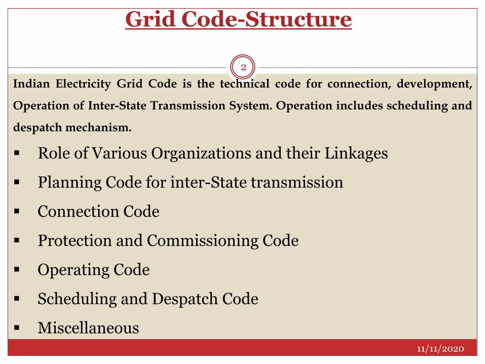
Indian Electricity Grid Code is the technical code for connection, development,
Operation of Inter-State Transmission System. Operation includes scheduling and
despatch mechanism.
Role of Various Organizations and their Linkages
Planning Code for inter-State transmission
Connection Code
Protection and Commissioning Code
Operating Code
Scheduling and Despatch Code
Miscellaneous11/11/2020
2
Grid Code 3
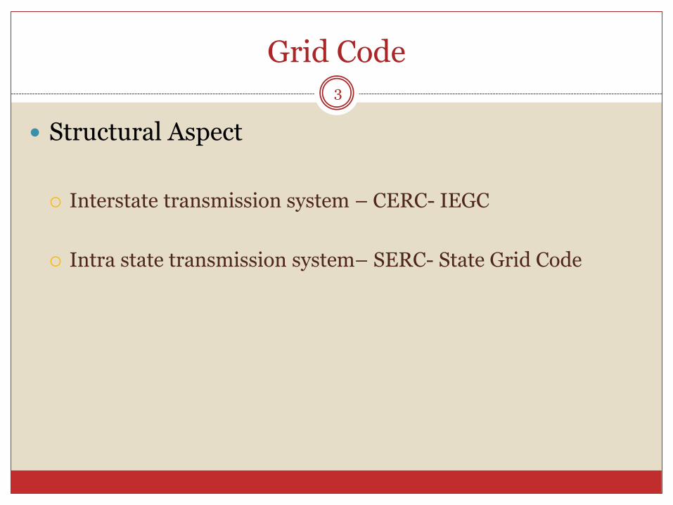
Structural Aspect
Interstate transmission system – CERC- IEGC
Intra state transmission system– SERC- State Grid Code
Evolution of Grid Code4
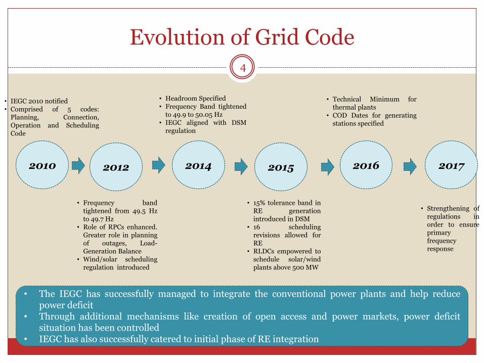
• IEGC 2010 notified• Comprised of 5 codes:
Planning, Connection,Operation and SchedulingCode
2012
• Frequency bandtightened from 49.5 Hzto 49.7 Hz
• Role of RPCs enhanced.Greater role in planningof outages, Load-Generation Balance
• Wind/solar schedulingregulation introduced
2014
• Headroom Specified• Frequency Band tightened
to 49.9 to 50.05 Hz• IEGC aligned with DSM
regulation
2010 2015 2016 2017
• 15% tolerance band inRE generationintroduced in DSM
• 16 schedulingrevisions allowed forRE
• RLDCs empowered toschedule solar/windplants above 500 MW
• Technical Minimum forthermal plants
• COD Dates for generatingstations specified
• Strengthening ofregulations inorder to ensureprimaryfrequencyresponse
• The IEGC has successfully managed to integrate the conventional power plants and help reducepower deficit
• Through additional mechanisms like creation of open access and power markets, power deficitsituation has been controlled
• IEGC has also successfully catered to initial phase of RE integration
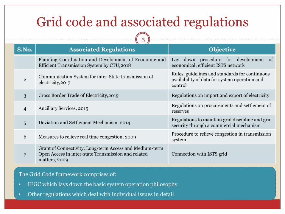
Grid code and associated regulations5
S.No. Associated Regulations Objective
1Planning Coordination and Development of Economic andEfficient Transmission System by CTU,2018
Lay down procedure for development ofeconomical, efficient ISTS network
2Communication System for inter-State transmission of electricity,2017
Rules, guidelines and standards for continuous availability of data for system operation and control
3 Cross Border Trade of Electricity,2019 Regulations on import and export of electricity
4 Ancillary Services, 2015Regulations on procurements and settlement of reserves
5 Deviation and Settlement Mechanism, 2014Regulations to maintain grid discipline and grid security through a commercial mechanism
6 Measures to relieve real time congestion, 2009Procedure to relieve congestion in transmission system
7Grant of Connectivity, Long-term Access and Medium-term Open Access in inter-state Transmission and related matters, 2009
Connection with ISTS grid
The Grid Code framework comprises of:
• IEGC which lays down the basic system operation philosophy
• Other regulations which deal with individual issues in detail
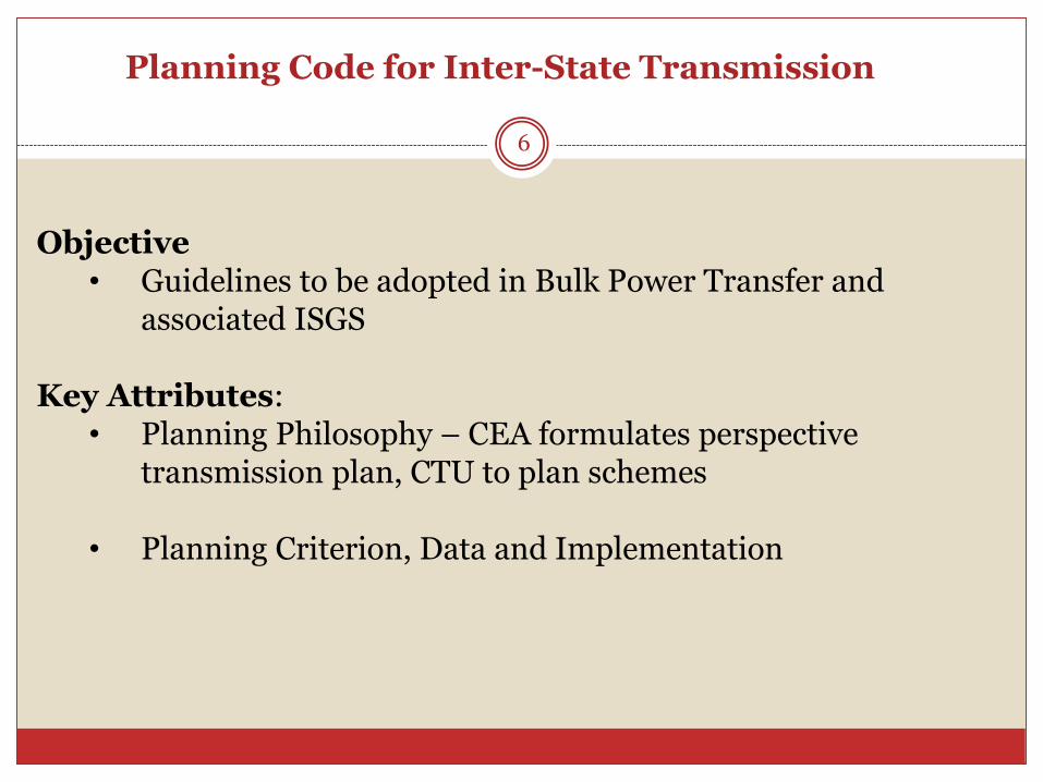
Planning Code for Inter-State Transmission
6
Objective• Guidelines to be adopted in Bulk Power Transfer and
associated ISGS
Key Attributes: • Planning Philosophy – CEA formulates perspective
transmission plan, CTU to plan schemes
• Planning Criterion, Data and Implementation
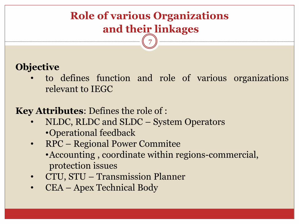
Role of various Organizations
and their linkages7
Objective• to defines function and role of various organizations
relevant to IEGC
Key Attributes: Defines the role of :• NLDC, RLDC and SLDC – System Operators
•Operational feedback• RPC – Regional Power Commitee
•Accounting , coordinate within regions-commercial, protection issues
• CTU, STU – Transmission Planner • CEA – Apex Technical Body
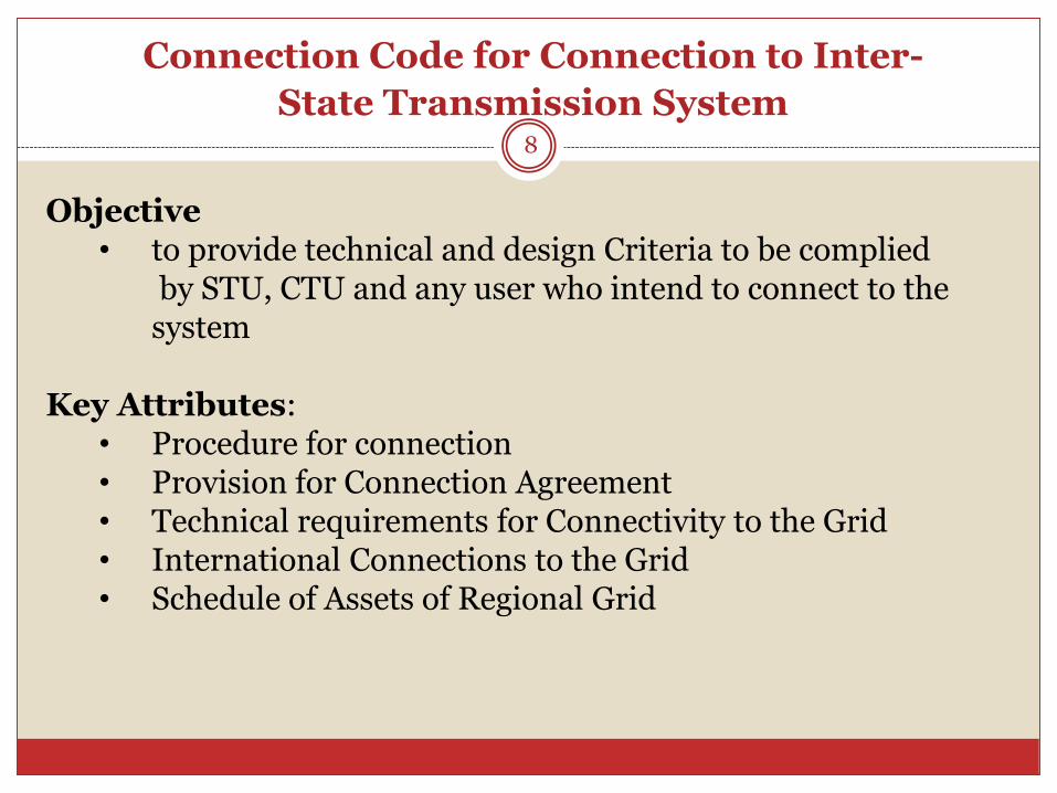
Connection Code for Connection to Inter-
State Transmission System8
Objective• to provide technical and design Criteria to be complied
by STU, CTU and any user who intend to connect to the system
Key Attributes: • Procedure for connection • Provision for Connection Agreement• Technical requirements for Connectivity to the Grid• International Connections to the Grid• Schedule of Assets of Regional Grid
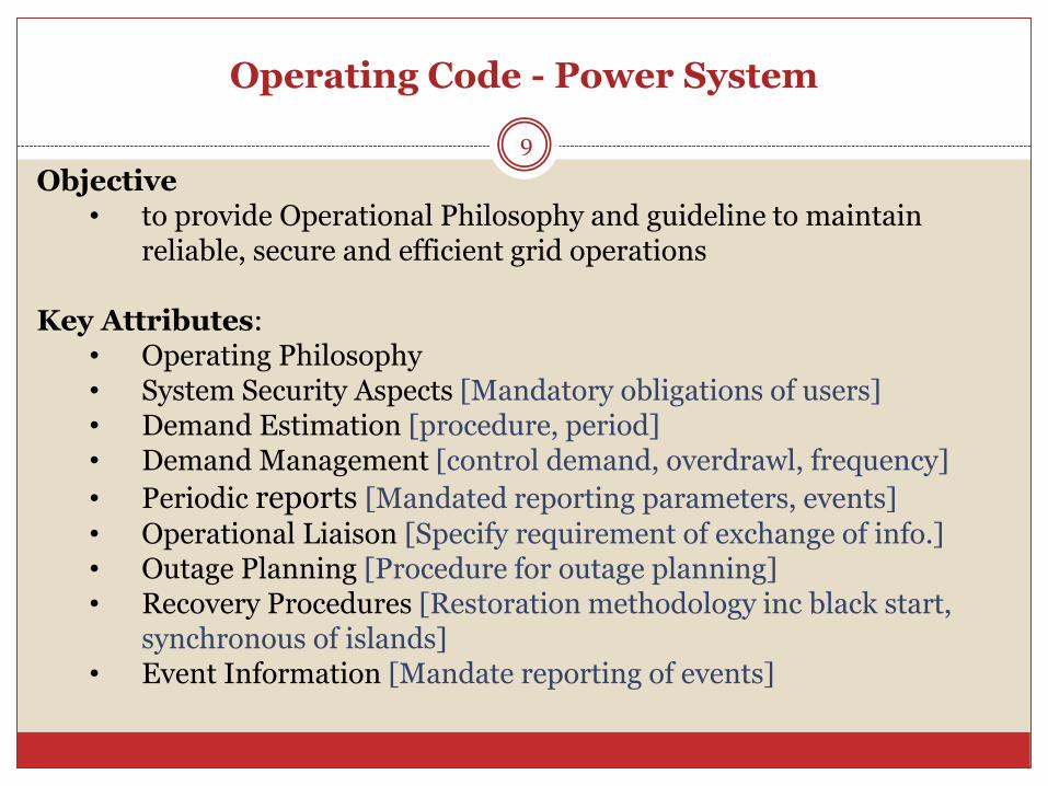
Operating Code - Power System
9
Objective• to provide Operational Philosophy and guideline to maintain
reliable, secure and efficient grid operations
Key Attributes: • Operating Philosophy • System Security Aspects [Mandatory obligations of users]• Demand Estimation [procedure, period]• Demand Management [control demand, overdrawl, frequency]
• Periodic reports [Mandated reporting parameters, events]• Operational Liaison [Specify requirement of exchange of info.]• Outage Planning [Procedure for outage planning]• Recovery Procedures [Restoration methodology inc black start,
synchronous of islands]• Event Information [Mandate reporting of events]
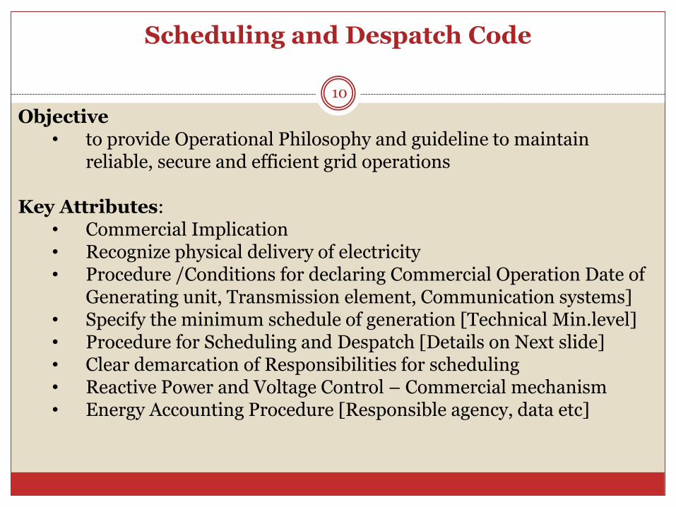
Scheduling and Despatch Code
10
Objective• to provide Operational Philosophy and guideline to maintain
reliable, secure and efficient grid operations
Key Attributes: • Commercial Implication • Recognize physical delivery of electricity• Procedure /Conditions for declaring Commercial Operation Date of
Generating unit, Transmission element, Communication systems]• Specify the minimum schedule of generation [Technical Min.level]• Procedure for Scheduling and Despatch [Details on Next slide]• Clear demarcation of Responsibilities for scheduling• Reactive Power and Voltage Control – Commercial mechanism• Energy Accounting Procedure [Responsible agency, data etc]
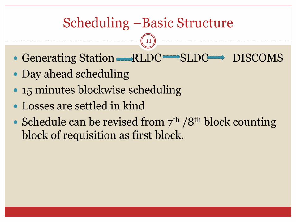
Scheduling –Basic Structure11
Generating Station RLDC SLDC DISCOMS
Day ahead scheduling
15 minutes blockwise scheduling
Losses are settled in kind
Schedule can be revised from 7th /8th block counting block of requisition as first block.
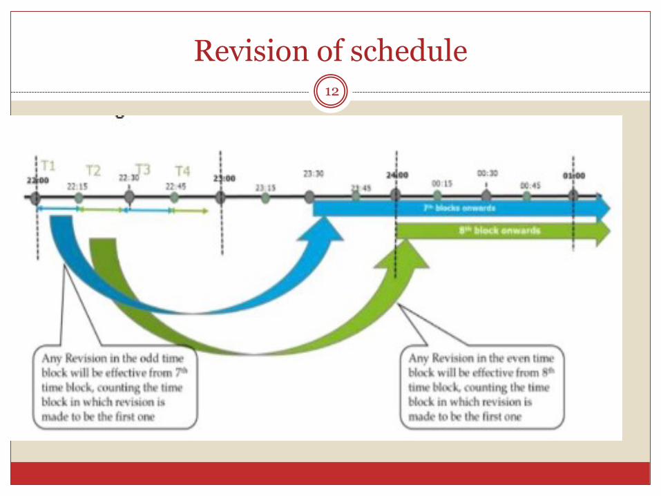
Revision of schedule12
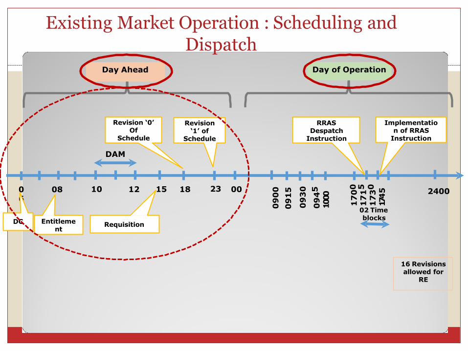
06
08 10 12
DAM
0023
Day Ahead Day of Operation
2400
DC Entitleme nt
Requisition
Revision ‘0’ Of
Schedule
Revision ‘1’ of
Schedule
16 Revisions allowed for
RE
RRASDespatch
Instruction
Implementatio n of RRAS
Instruction
02 Time blocks
15 18
09
00
09
15
09
30
09
45
1000
17
00
17
15
17
30
174
5
Existing Market Operation : Scheduling andDispatch
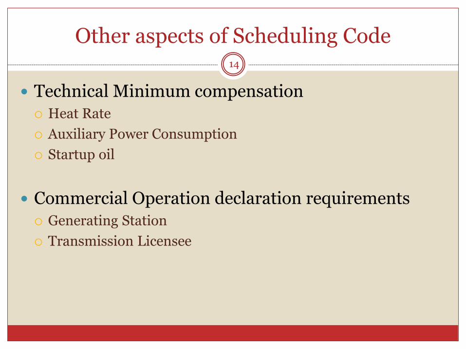
Other aspects of Scheduling Code14
Technical Minimum compensation
Heat Rate
Auxiliary Power Consumption
Startup oil
Commercial Operation declaration requirements
Generating Station
Transmission Licensee
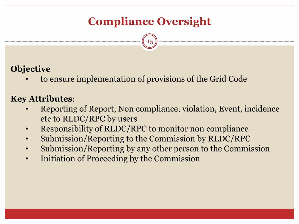
Compliance Oversight
15
Objective• to ensure implementation of provisions of the Grid Code
Key Attributes: • Reporting of Report, Non compliance, violation, Event, incidence
etc to RLDC/RPC by users• Responsibility of RLDC/RPC to monitor non compliance• Submission/Reporting to the Commission by RLDC/RPC• Submission/Reporting by any other person to the Commission• Initiation of Proceeding by the Commission

Scheduling and Despatch -Energy Accounting
16
Energy Accounting• Provision for Regional Level Energy Accounting• Mandates the responsibility of Regional Energy
Account (REA)• Provides periodicity for issuance of REA• Also mandate users to supply all commercial
information for energy accounting purpose
Metering• Metering is governed as per Central Electricity
Authority (Installation and Operation ofMeters) Regulations, 2006 – It providesLocation, Standards for accuracy, interval for energyrecording, Redundancy, Checking etc.
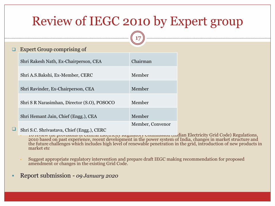
Review of IEGC 2010 by Expert group
Expert Group comprising of
Terms of Reference To review the provisions of Central Electricity Regulatory Commission (Indian Electricity Grid Code) Regulations,
2010 based on past experience, recent development in the power system of India, changes in market structure and the future challenges which includes high level of renewable penetration in the grid, introduction of new products in market etc
Suggest appropriate regulatory intervention and prepare draft IEGC making recommendation for proposed amendment or changes in the existing Grid Code.
Report submission - 09 January 2020
17
Shri Rakesh Nath, Ex-Chairperson, CEA Chairman
Shri A.S.Bakshi, Ex-Member, CERC Member
Shri Ravinder, Ex-Chairperson, CEA Member
Shri S R Narasimhan, Director (S.O), POSOCO Member
Shri Hemant Jain, Chief (Engg.), CEA Member
Shri S.C. Shrivastava, Chief (Engg.), CERC
Member, Convenor
Types of Reserves
There shall be different levels of reserves such as primary, secondary and tertiaryfor the purpose of frequency control and regulating area control error. Thereserves shall be deployed by each control area connected with the grid.
Provision for primary reserve (governor droop response) shall be mandatoryas per this code. The primary response of machines shall be verified by theload despatch centres during grid events.
Secondary reserves (automatic generation control) shall be deployed by acontrol area as per this code.
Tertiary reserves shall be deployed by control area as per this code.
Any other type of reserves required to be deployed in the interest of gridsecurity as per the direction of the SLDC, RLDC or NLDC.
ESS reserves may be deployed by SLDC, RLDC or NLDC if requireddepending on the impact of variability of renewable generation and the needfor frequency control.
Aspects of Renewables19
Mandatory Primary response from Solar and wind based generation
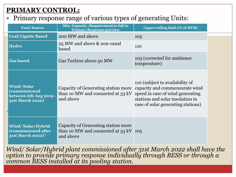
PRIMARY CONTROL: Primary response range of various types of generating Units:
^
Wind/ Solar/Hybrid plant commissioned after 31st March 2022 shall have the option to provide primary response individually through BESS or through a common BESS installed at its pooling station.
Fuel/ SourceMin. Capacity /Requirement to fall in
Primary Response purviewUpper ceiling limit (% of MCR)
Coal/Lignite Based 200 MW and above 105
Hydro25 MW and above & non-canal based
110
Gas based Gas Turbine above 50 MW105 (corrected for ambience temperature)
Wind/ Solar (commissioned between 6th Aug 2019 -31st March 2022)
Capacity of Generating station more than 10 MW and connected at 33 kV and above
110 (subject to availability of capacity and commensurate wind speed in case of wind generating stations and solar insolation in case of solar generating stations)
Wind/ Solar/Hybrid (commissioned after 31st March 2022)^
Capacity of Generating station more than 10 MW and connected at 33 kV and above
105
CEA Regulations
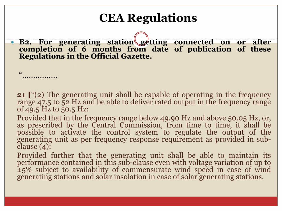
B2. For generating station getting connected on or aftercompletion of 6 months from date of publication of theseRegulations in the Official Gazette.
“………….…
21 [“(2) The generating unit shall be capable of operating in the frequencyrange 47.5 to 52 Hz and be able to deliver rated output in the frequency rangeof 49.5 Hz to 50.5 Hz:Provided that in the frequency range below 49.90 Hz and above 50.05 Hz, or,as prescribed by the Central Commission, from time to time, it shall bepossible to activate the control system to regulate the output of thegenerating unit as per frequency response requirement as provided in sub-clause (4):Provided further that the generating unit shall be able to maintain itsperformance contained in this sub-clause even with voltage variation of up to±5% subject to availability of commensurate wind speed in case of windgenerating stations and solar insolation in case of solar generating stations.

Continued……. (CEA Regulation)
(4) The generating stations with installed capacity of more than 10 MW connectedat voltage level of 33 kV and above –
(i) shall be equipped with the facility to control active power injection inaccordance with a set point, capable of being revised based on directions ofthe State Load Dispatch Centre or Regional Load Dispatch Centre, as the casemay be;
(ii) shall have governors or frequency controllers of the units at a droop of 3 to6% and a dead band not exceeding ±0.03 Hz:
Provided that for frequency deviations in excess of 0.3 Hz, the GeneratingStation shall have the facility to provide an immediate (within 1 second) realpower primary frequency response of at least 10% of the maximumAlternating Current active power capacity;
Secondary Control
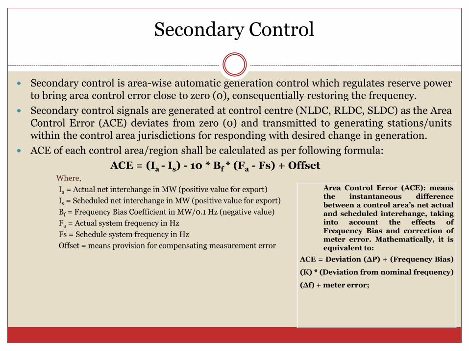
Secondary control is area-wise automatic generation control which regulates reserve powerto bring area control error close to zero (0), consequentially restoring the frequency.
Secondary control signals are generated at control centre (NLDC, RLDC, SLDC) as the AreaControl Error (ACE) deviates from zero (0) and transmitted to generating stations/unitswithin the control area jurisdictions for responding with desired change in generation.
ACE of each control area/region shall be calculated as per following formula:
ACE = (Ia - Is) - 10 * Bf * (Fa - Fs) + OffsetWhere,
Ia = Actual net interchange in MW (positive value for export)
Is = Scheduled net interchange in MW (positive value for export)
Bf = Frequency Bias Coefficient in MW/0.1 Hz (negative value)
Fa = Actual system frequency in Hz
Fs = Schedule system frequency in Hz
Offset = means provision for compensating measurement error
Area Control Error (ACE): meansthe instantaneous differencebetween a control area’s net actualand scheduled interchange, takinginto account the effects ofFrequency Bias and correction ofmeter error. Mathematically, it isequivalent to:
ACE = Deviation (∆P) + (Frequency Bias)
(K) * (Deviation from nominal frequency)
(∆f) + meter error;
Continued…..(Secondary control)
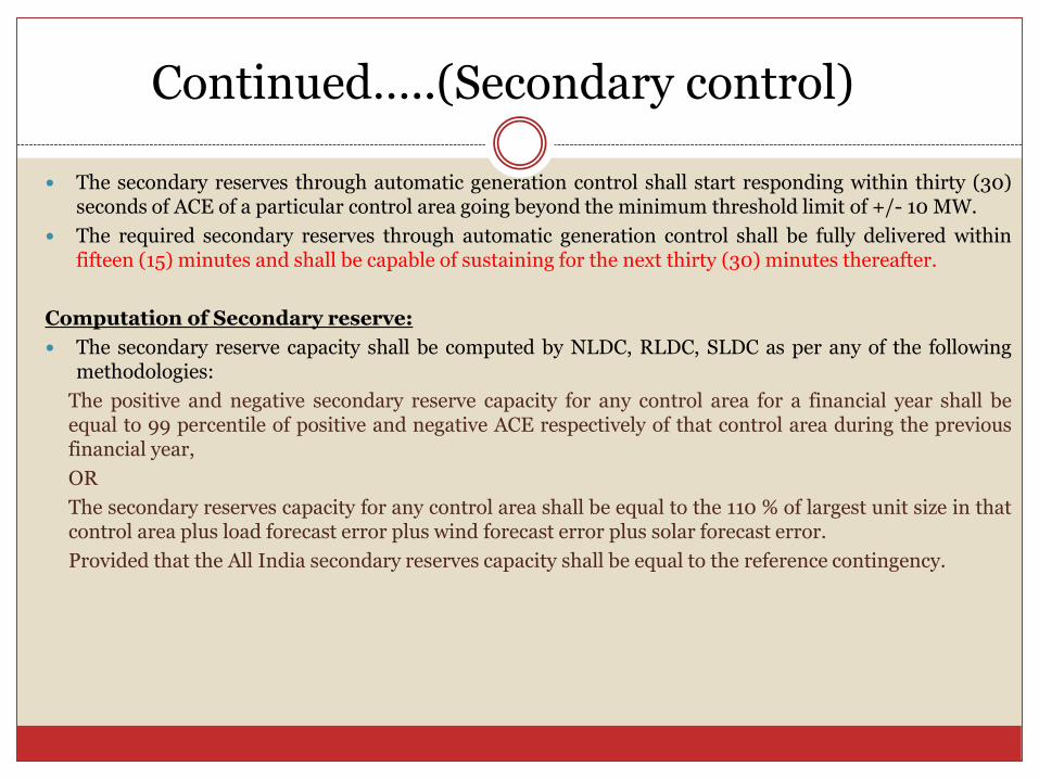
The secondary reserves through automatic generation control shall start responding within thirty (30)seconds of ACE of a particular control area going beyond the minimum threshold limit of +/- 10 MW.
The required secondary reserves through automatic generation control shall be fully delivered withinfifteen (15) minutes and shall be capable of sustaining for the next thirty (30) minutes thereafter.
Computation of Secondary reserve:
The secondary reserve capacity shall be computed by NLDC, RLDC, SLDC as per any of the followingmethodologies:
The positive and negative secondary reserve capacity for any control area for a financial year shall beequal to 99 percentile of positive and negative ACE respectively of that control area during the previousfinancial year,
OR
The secondary reserves capacity for any control area shall be equal to the 110 % of largest unit size in thatcontrol area plus load forecast error plus wind forecast error plus solar forecast error.
Provided that the All India secondary reserves capacity shall be equal to the reference contingency.
Continued…….
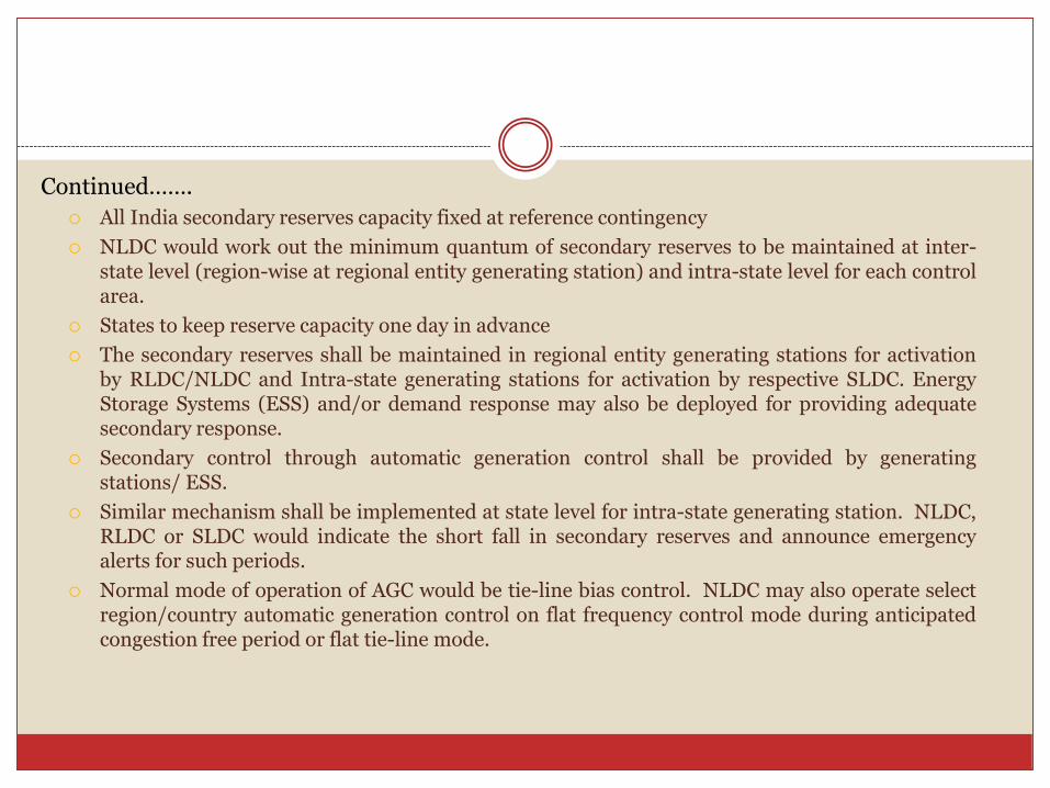
All India secondary reserves capacity fixed at reference contingency
NLDC would work out the minimum quantum of secondary reserves to be maintained at inter-state level (region-wise at regional entity generating station) and intra-state level for each controlarea.
States to keep reserve capacity one day in advance
The secondary reserves shall be maintained in regional entity generating stations for activationby RLDC/NLDC and Intra-state generating stations for activation by respective SLDC. EnergyStorage Systems (ESS) and/or demand response may also be deployed for providing adequatesecondary response.
Secondary control through automatic generation control shall be provided by generatingstations/ ESS.
Similar mechanism shall be implemented at state level for intra-state generating station. NLDC,RLDC or SLDC would indicate the short fall in secondary reserves and announce emergencyalerts for such periods.
Normal mode of operation of AGC would be tie-line bias control. NLDC may also operate selectregion/country automatic generation control on flat frequency control mode during anticipatedcongestion free period or flat tie-line mode.
OUTAGE PLANNING
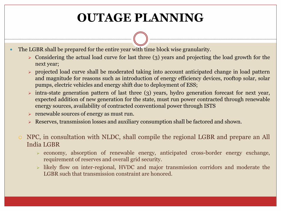
The LGBR shall be prepared for the entire year with time block wise granularity.
Considering the actual load curve for last three (3) years and projecting the load growth for thenext year;
projected load curve shall be moderated taking into account anticipated change in load patternand magnitude for reasons such as introduction of energy efficiency devices, rooftop solar, solarpumps, electric vehicles and energy shift due to deployment of ESS;
intra-state generation pattern of last three (3) years, hydro generation forecast for next year,expected addition of new generation for the state, must run power contracted through renewableenergy sources, availability of contracted conventional power through ISTS
renewable sources of energy as must run.
Reserves, transmission losses and auxiliary consumption shall be factored and shown.
NPC, in consultation with NLDC, shall compile the regional LGBR and prepare an AllIndia LGBR
economy, absorption of renewable energy, anticipated cross-border energy exchange,requirement of reserves and overall grid security.
likely flow on inter-regional, HVDC and major transmission corridors and moderate theLGBR such that transmission constraint are honored.
OPERATIONAL PLANNING STUDY
Based on the operational planning analysis data, operational planningstudy shall be carried out by various agencies as defined for the varioustime horizons.
SLDC, RLDC and NLDC shall utilize network estimation tool integratedin their EMS/SCADA system for the real time operational planningstudy.
SLDC, RLDC and NLDC shall perform day-ahead/ weekly/ monthly/yearly operational study.
SLDC shall carry out total transfer capability/available transfercapability on three months ahead basis.
Defense mechanisms like system protection scheme, load-rejectionscheme, generation run-back or any other scheme for system securityshall be proposed by concerned user or SLDC or RLDC or NLDC andshall be deployed as finalized by RPC.
Connection Code28
NLDC/RLDC in consultation with CTU shall carryout a joint system study six (6) months beforeexpected date of first energization of a new powersystem element to identify operational constraints, ifany. For this purpose, the connectivity grantee,transmission licensee and SLDC/STU shall furnishall technical data including that of its embeddedgenerators and other elements to the CTU/NLDC fornecessary technical studies.
Connection Code(contd.)
Tests required for thermal (coal/lignite) generating
stations : Operation of control load of fifty (50) percent of MCR as per CEA standards for a
sustained period of four (4) hours.
Ramp-up from fifty (50) percent MCR to rated capacity at a ramp rate of atleastthree (3) percent of MCR per minute. Sustained operation at MCR for one (1) hour.
To demonstrate overload capability with valve wide open as per Central ElectricityAuthority (Technical Standards for Construction of Electrical Plants and ElectricLines) Regulations, 2010. Sustained operation at this level for atleast five (5)minutes.
Ramp-down from MCR to fifty (50) percent of MCR at a ramp rate of atleast three(3) percent of MCR per minute.
Testing primary response through injecting a frequency test signal with a step
change of ± 0.1 Hz at 60%, 75% and 100% load.
Reactive power capability test as per the generator capability curve considering
over-excitation and under-excitation limiter settings.
11/11/2020POSOCO
29
Connection Code(contd.)
Tests/Documents required for hydro stations :Documents The generating company shall submit the document for turbine
characteristics curve indicating the operating zone(s) and prohibited zone(s). In order to demonstrate operating flexibility of generating unit, it shall be operated below and above the prohibited zone(s).
Tests Testing primary response through injecting a frequency test signal
with a step change of ± 0.1 Hz for various loadings within the operating zone.
Reactive power capability test as per the generator capability curve considering over-excitation and under-excitation limiter settings.
Black start capability. Operation in synchronous condenser mode wherever designed. The tests will be performed considering the water availability and
head.
11/11/2020POSOCO
30
Connection Code(contd.)
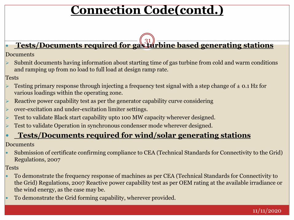
Tests/Documents required for gas turbine based generating stations Documents
Submit documents having information about starting time of gas turbine from cold and warm conditions and ramping up from no load to full load at design ramp rate.
Tests
Testing primary response through injecting a frequency test signal with a step change of ± 0.1 Hz for various loadings within the operating zone.
Reactive power capability test as per the generator capability curve considering
over-excitation and under-excitation limiter settings.
Test to validate Black start capability upto 100 MW capacity wherever designed.
Test to validate Operation in synchronous condenser mode wherever designed.
Tests/Documents required for wind/solar generating stationsDocuments
Submission of certificate confirming compliance to CEA (Technical Standards for Connectivity to the Grid) Regulations, 2007
Tests
To demonstrate the frequency response of machines as per CEA (Technical Standards for Connectivity to the Grid) Regulations, 2007 Reactive power capability test as per OEM rating at the available irradiance or the wind energy, as the case may be.
To demonstrate the Grid forming capability, wherever provided.
11/11/2020
31
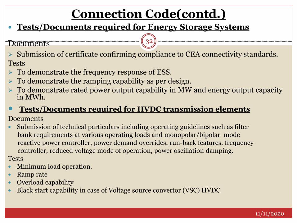
Connection Code(contd.) Tests/Documents required for Energy Storage Systems
Documents
Submission of certificate confirming compliance to CEA connectivity standards. Tests To demonstrate the frequency response of ESS. To demonstrate the ramping capability as per design. To demonstrate rated power output capability in MW and energy output capacity
in MWh.
Tests/Documents required for HVDC transmission elements
Documents Submission of technical particulars including operating guidelines such as filter
bank requirements at various operating loads and monopolar/bipolar mode reactive power controller, power demand overrides, run-back features, frequency controller, reduced voltage mode of operation, power oscillation damping.
Tests Minimum load operation. Ramp rate Overload capability Black start capability in case of Voltage source convertor (VSC) HVDC
11/11/2020
32
Connection Code(contd.)
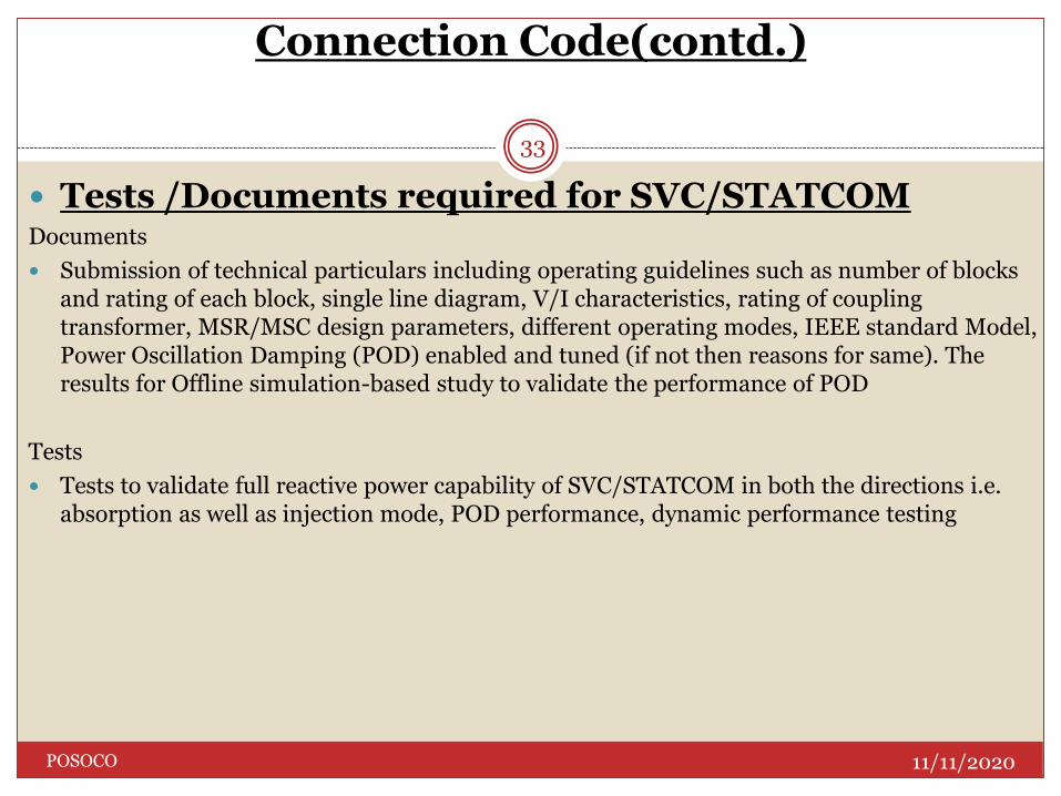
Tests /Documents required for SVC/STATCOM Documents
Submission of technical particulars including operating guidelines such as number of blocks and rating of each block, single line diagram, V/I characteristics, rating of coupling transformer, MSR/MSC design parameters, different operating modes, IEEE standard Model, Power Oscillation Damping (POD) enabled and tuned (if not then reasons for same). The results for Offline simulation-based study to validate the performance of POD
Tests
Tests to validate full reactive power capability of SVC/STATCOM in both the directions i.e. absorption as well as injection mode, POD performance, dynamic performance testing
11/11/2020POSOCO
33
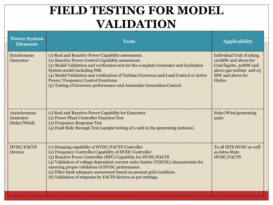
FIELD TESTING FOR MODEL VALIDATION
Power System Elements
Tests Applicability
Synchronous Generator
(1) Real and Reactive Power Capability assessment.(2) Reactive Power Control Capability assessment.(3) Model Validation and verification test for the complete Generator and Excitation System model including PSS.(4) Model Validation and verification of Turbine/Governor and Load Control or Active Power/ Frequency Control Functions. (5) Testing of Governor performance and Automatic Generation Control.
Individual Unit of rating 100MW and above for Coal/lignite, 50MW and above gas turbine and 25 MW and above for Hydro.
Asynchronous Generator(Solar/Wind)
(1) Real and Reactive Power Capability for Generator (2) Power Plant Controller Function Test (3) Frequency Response Test (4) Fault Ride through Test (sample testing of a unit in the generating stations).
Solar/Wind generating units
HVDC/FACTS Devices
(1) Damping capability of HVDC/FACTS Controller (2) Frequency Controller Capability of HVDC Controller (3) Reactive Power Controller (RPC) Capability for HVDC/FACTS (4) Validation of voltage dependent current order limiter (VDCOL) characteristic for ensuring proper validation of HVDC performance(5) Filter bank adequacy assessment based on present grid condition.(6) Validation of response by FACTS devices as per settings.
To all ISTS HVDC as well as Intra-State HVDC/FACTS
Resource Adequacy35
Each distribution licensee shall ensure demonstrable resource adequacy as specified by the respective SERC for the next five (5) years starting 1st April of the next year. Adequacy statement containing a list of such resources along with associated capacities shall be submitted to the respective STU and SERC. STU shall submit the same to CTU.
Qualified Coordinating Agency36
Aggregating RE generators
Tightening Forecasting Errors the cost of forecasting infrastructure and error in forecasting
can be reduced by doing a forecast over a large geographical area.
Successfully demonstrated for intra-state renewable generators in Karnataka, Andhra Pradesh and Rajasthan.
Experience of aggregating internationally?– parameters of aggregation
Roles and functions of QCA37
To act as the nodal agency on behalf of the wind, solar and hybrid generators including energy storage system connected to one or more pooling stations represented by it for the purpose of Grid Code in general and operational and scheduling liaison in particular.
To undertake generation forecasting, declaration of combined capability on behalf of generators, energy storage system at one or more pooling stations to the concerned load despatch centre for the purpose of scheduling.
To undertake scheduling, metering and accounting of energy. QCA shall be responsible for pooling of declared availability, de-pooling of despatch schedule and DSM account as necessary.
To operate and maintain a co-ordination centre manned by qualified and competent personnel for round the clock operational co-ordination and information exchange with the concerned Load Despatch Centre and generating stations.
To settle all payments as per DSM Regulations arising out of deviations from its aggregated schedule given by relevant LDC.
Any instruction or direction given by the LDC to QCA shall be deemed to have been given to the renewable generator represented by it.
UFR Settings
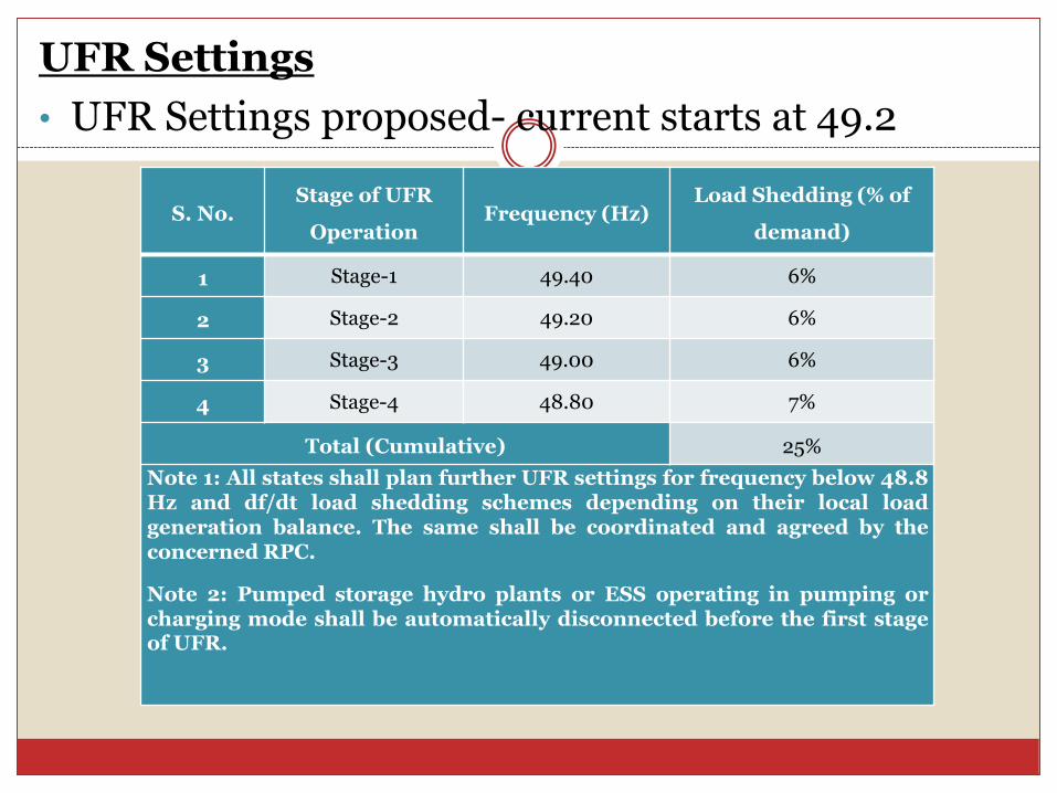
• UFR Settings proposed- current starts at 49.2
S. No.Stage of UFR
OperationFrequency (Hz)
Load Shedding (% of
demand)
1 Stage-1 49.40 6%
2 Stage-2 49.20 6%
3 Stage-3 49.00 6%
4 Stage-4 48.80 7%
Total (Cumulative) 25%
Note 1: All states shall plan further UFR settings for frequency below 48.8Hz and df/dt load shedding schemes depending on their local loadgeneration balance. The same shall be coordinated and agreed by theconcerned RPC.
Note 2: Pumped storage hydro plants or ESS operating in pumping orcharging mode shall be automatically disconnected before the first stageof UFR.

Basis of UFR proposal
At present, there are four stages of Under-Frequency Load-Shedding(UFLS) relays which are set at 49.2 Hz, 49.0 Hz, 48.8 Hz, and 48.6 Hz inNR, WR, ER, SR, and NER. These settings were last raised in end 2013before synchronization of Southern region with rest of the grid.
In addition to UFLS relays, df/dt relays are also installed in NR, WR, andSR grids. In NR and WR df/dt relays are set to get armed at 49.9 Hz to shedload automatically if the rate of fall of frequency is faster than 0.1, 0.2, or0.3 Hz/s (i.e., three stages). In SR, however, the frequency at which UFLS isarmed and the rate thresholds are 49.5 Hz & 0.2 Hz/s, 49.3 Hz & 0.2 Hz/s,and 49.3 Hz & 0.3 Hz/s for the three stages, respectively.
The quantum of load shedding at each stage ofunderfrequency may be set in terms of percentage of totalload at regional as well as national level. The similarpractice is being followed in Continental Europe asbrought out in “Commission Regulation on establishinga network code on emergency and restoration.”
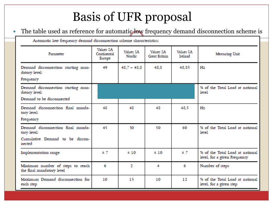
Basis of UFR proposal The table used as reference for automatic low frequency demand disconnection scheme is
given below:
Unit Commitment, Scheduling And Despatch Code For
Physical Delivery Of Electrical Energy
Security Constrained Unit Commitment (SCUC)
The SCUC exercise shall take into account optimal cost,adequate reserves, ramping requirements factoring securityconstraint
NLDC, through RLDC shall advise the regional entitygenerators to commit or de-commit the unit
Based on the SCUC instructions from RLDC, the generatingstation shall revise the on-bar DC (with due consideration toramp up/down capability), off-bar DC and ramp up/downrate.
11/11/2020POSOCO
41

Monitoring And Compliance Code Newly drafted chapter
The performance of all users, CTU, STU, NLDC, RLDC, SLDC and RPC with respect to grid code compliance shall be assessed periodically
to ensure compliance, two methodologies shall be followed:
(a) Self-Audit (b) Compliance Audit
All users, CTU, STU, NLDC, RLDC, RPC and SLDC shall conduct annual self-audits to review compliance of the regulations and submit by 31st July of every year
The self-audit reports by users shall be submitted to the concernedRLDC/SLDC. The self-audit reports of NLDC, RLDC, CTU, and RPCSecretariat shall be submitted to CERC. The self-audit report of SLDC andSTU shall be submitted to SERC.
Monitoring agency (RLDC or SLDC as the case may be) shall track theprogress of compliances and report non-compliance to CERC.
CERC may order independent third-party compliance audit for any user,CTU, NLDC, RLDC and RPC as deemed necessary.
11/11/2020POSOCO
42
Relationship between CERC Grid Code and State Grid Code
43
lays down the regulations, guidelines and standards to be followed by various agencies and participants in the State Transmission System to plan, develop, maintain and operate the State Transmission System
Communication, protection systems within State
Demand management
Intra-state generators
Harmonisation between grid codes44
Resource adequacy – reserves adequacy
Primary Response
Secondary response
Tertiary response
Renewable Integration – MUST RUN

THANK YOU
45