Embed Size (px)
Citation preview
TECHNICAL SPECIFICATION No.
I-ET-3010.1M-1200-459-P4X-001
CLIENT: SRGE
SHEET: 1
of 12
JOB: REFERENCE BASIC DESIGN 1001056398 0010
AREA: BUZIOS
DP&T-SRGE TITLE:
PRINTED CIRCUIT HEAT EXCHANGER SPECIFICATION NP-1
ESUP
MICROSOFT WORD / V.2013 / I-ET-3010.1M-1200-459-P4X-001_0.DOC
INDEX OF REVISIONS
REV. DESCRIPTION AND/OR REVISED SHEET
0
ORIGINAL ISSUE
REV. 0 REV. A REV. B REV. C REV. D REV. E REV. F REV. G REV. H
DATE JUL/17/19
DESIGN ESUP
EXECUTION IZAO
CHECK FABIANA
APPROVAL TMCAMPOS
INFORMATION IN THIS DOCUMENT IS PROPERTY OF PETROBRAS, BEING PROHIBITED OUTSIDE OF THEIR PURPOSE.
FORM OWNED TO PETROBRAS N-0381 REV.L
PRELIMIN
ARY

TECHNICAL SPECIFICATION No.
I-ET-3010.1M-1200-459-P4X-001 REV.
0 AREA:
BUZIOS SHEET:
2 of 12
TITLE:
PRINTED CIRCUIT HEAT EXCHANGER SPECIFICATION NP-1
ESUP
SUMMARY
1 SCOPE ................................................................................................................................................ 3
2 DEFINITIONS ..................................................................................................................................... 3
3 MANUFACTURER’S OBLIGATIONS ................................................................................................ 3
4 CODES AND STANDARDS ............................................................................................................... 4
5 GENERAL REQUIREMENTS ............................................................................................................. 5
6 EQUIPMENT SPECIFICATION .......................................................................................................... 5
7 SURFACE PREPARATION AND PAINTING ..................................................................................... 7
8 NAMEPLATES AND SIGNS ............................................................................................................... 7
9 CERTIFICATION REQUIREMENTS .................................................................................................. 8
10 INSPECTION, TESTING AND COMMISSIONING ............................................................................. 9
11 PREPARATION FOR SHIPMENT .................................................................................................... 10
ANNEX 1 – ALLOWABLE NOZZLES LOADS ........................................................................................ 12
PRELIMIN
ARY
TECHNICAL SPECIFICATION No.
I-ET-3010.1M-1200-459-P4X-001 REV.
0 AREA:
BUZIOS SHEET:
3 of 12
TITLE:
PRINTED CIRCUIT HEAT EXCHANGER SPECIFICATION NP-1
ESUP
1 SCOPE
1.1 This Technical Specification contains the minimum requirements for the design, engineering, materials, fabrication, inspection, testing and certification of all Printed Circuit Heat Exchangers for the FPSO’s topsides.
2 DEFINITIONS
2.1 Within the contents of this Technical Specification, the following definitions shall be observed:
Shall Shall is an absolute requirement to be followed strictly in order to conform to the specification.
MANUFACTURER Firm or organization responsible for the thermal and mechanical design, fabrication and test of the heat exchanger.
FPSO An abbreviation of “Floating Production Storage and Offloading Vessel”.
Classification Society
Means such authority or organization appointed to ensure conformity by the MANUFACTURER with all requirements necessary to obtain certification or classification of the goods and/or services described herein.
3 MANUFACTURER’S OBLIGATIONS
3.1 Compliance with the requirements or recommendations of this Specification or other specifications shall in no case reduce or eliminate MANUFACTURER´s responsibility, who will bear full responsibility at all times for design and fabrication of the equipment.
3.2 MANUFACTURER shall be responsible for the thermal and mechanical design. MANUFACTURER shall guarantee that the equipment meets the performance specified at fouled condition. PETROBRAS reserves the right to check the mechanical and fabrication design prepared by MANUFACTURER.
3.3 MANUFACTURER’s responsibility shall also include but not limited to:
• Resolving all engineering questions and/or problems relating to design and manufacture.
• Providing details of any design and manufacture sub-vendor as requested.
3.4 MANUFACTURER shall design the equipment for the full range of process conditions as specified in data sheets. Furthermore, the equipment shall be designed for the full range of operational environmental conditions. Special
PRELIMIN
ARY
TECHNICAL SPECIFICATION No.
I-ET-3010.1M-1200-459-P4X-001 REV.
0 AREA:
BUZIOS SHEET:
4 of 12
TITLE:
PRINTED CIRCUIT HEAT EXCHANGER SPECIFICATION NP-1
ESUP
consideration must be given to designing the printed circuit heat exchangers to withstand and operate under the motion conditions as specified.
3.5 It is the MANUFACTURER’s responsibility to submit to the Classification Society the documentation as described in the latest edition of their rules for equipment on offshore facilities. All elements of the heat exchanger package, including sub-orders, shall be of proven design and well within the MANUFACTURER’s actual experience.
4 CODES AND STANDARDS
4.1 Printed Circuit Heat Exchangers designed and fabricated in accordance with this Technical Specification shall comply, where applicable, with the documents mentioned on item 4.2 below. Equipment shall also be in accordance with rules and regulation of the Classification Society applied for the unit. In case of conflict between Classification Society rules and regulations and this Technical Specification, the MANUFACTURER must submit this issue to PETROBRAS.
4.2 Unless noted, the edition and addenda of each document listed below shall be used as current on the date of this specification.
API 945 Avoiding Environmental Cracking In Amine Units;
ASME BPVC Sections II, V, VIII and IX;
ASME B16.5 Pipe Flanges and Flanged Fittings (NPS ½ Through NPS 24);
AWS D1.1 Structural Welding Code - Steel 20th Edition
API RP 582 Welding Guidelines for the Chemical, Oil, and Gas Industries.
ABNT NBR 6123 “Forças devidas ao Vento em Edificações” (wind load calculation) Brazilian Standard
NORSOK L-005 Compact flanged connections
NR-13 Caldeiras, Vasos de Pressão, Tubulação e Tanques Metálicos de Armazenamento (Boilers, Pressure Vessels, Piping and Mettalic StorageTanks) Regulatory Standard from Brazilian Labor Ministry.
NR-26 “Sinalização de Segurança” (Safety Signalling) Regulatory Standard from Brazilian Labor Ministry.
NR-37 “Segurança e Saúde em Plataformas de Petróleo” (Safety and Health in Oil Platforms) Regulatory Standard from Brazilian Labor Ministry.
ISO 15156 Petroleum and natural gas industries - Materials for Use in H2S-containing Environments in Oil and Gas Production
PRELIMIN
ARY
TECHNICAL SPECIFICATION No.
I-ET-3010.1M-1200-459-P4X-001 REV.
0 AREA:
BUZIOS SHEET:
5 of 12
TITLE:
PRINTED CIRCUIT HEAT EXCHANGER SPECIFICATION NP-1
ESUP
IEC-61892-6 Mobile and Fixed Offshore Units – Electrical Installations - Installation
IEC-61892-7 Mobile and Fixed Offshore Units – Electrical Installations – Hazardous Area
IEC-60092-502 Electrical Installation in Ships – Tankers – Special Features
5 GENERAL REQUIREMENTS
5.1 All Printed Circuit Heat Exchangers shall comply with the requirements of NR-13, where applicable.
5.2 Exchangers shall be suitable for operation in accordance with the area classification presented in I-DE-3010.1M-5400-94A-P4X-001 – AREA CLASSIFICATION - GENERAL.
5.3 Design Loads:
In addition to the Code described loads and loads due to vessel motion described in the I-RL-3010.1M-1350-960-P4X-009 - MOTION ANALYSIS, the following design loads must be considered where relevant:
• Equipment transportation and erection loads
• Nozzle loads as described in this specification.
• Thermal loads.
• Wind load
• Weight load
A wind basic velocity of 40 m/s, referenced to 10m above mean sea level, shall be considered for wind load calculations in accordance with ABNT NBR 6123 Standard.
5.4 MANUFACTURER shall design and fabricate the equipment for a minimum lifetime of 25 years.
5.5 English language shall be used for all design and engineering documents, for drawings and for communication with PETROBRAS.
6 EQUIPMENT SPECIFICATION
MANUFACTURER shall be responsible for supplying complete and fully operative printed circuit heat exchangers in accordance with the requirements of this specification, attachments and standards referenced herein.
PRELIMIN
ARY

TECHNICAL SPECIFICATION No.
I-ET-3010.1M-1200-459-P4X-001 REV.
0 AREA:
BUZIOS SHEET:
6 of 12
TITLE:
PRINTED CIRCUIT HEAT EXCHANGER SPECIFICATION NP-1
ESUP
6.1 Design Requirements
6.1.1 The heat exchangers shall be designed, manufactured, inspected and tested in accordance with the requirements stated herein and ASME VIII. The deviations from this Technical Specification shall be previously approved by PETROBRAS.
6.1.2 The heat exchangers shall be provided with lifting lugs for single point lifting. The lifting lugs shall be designed with a safety factor of 2.0.
6.1.3 The heat exchangers shall be provided with 2 (two) diametrically opposite earthing bosses. Equipment, accessories, piping and structures shall be grounded according to requirements of IEC 61892-6 and IEC 60092-502. Besides these standards, for installations in hazardous area, the grounding requirements of IEC 61892-7 shall be complied with.
6.1.4 The Heat exchangers shall be provided with clips for personnel protection insulation attachment, which shall ensure a temperature below 60° C on the outside surface and shall be of non hygroscopic material.
6.1.5 Where the design of the exchanger allows, maintenance nozzles shall be included on the exchanger. MANUFACTURER shall recommend size and location of these connections.
6.1.6 MANUFACTURER shall provide a tap pressure connection between the integral strainer and the PCHE on the gas inlet.
6.1.7 The heat exchangers shall be provided with mounting feet or brackets capable of handling the dynamic forces as stated in I-RL-3010.1M-1350-960-P4X-009 - MOTION ANALYSIS.
6.1.8 MANUFACTURER shall supply an integral T-type (or similar) strainer on the gas inlet and a separate Duplex in line cleanable strainer for the coolant side. The strainer aperture for both cases shall be specified by MANUFACTURER.
6.1.9 MANUFACTURER shall inform the coolant minimum requirements to be met on design, commissioning and operation phases in order to guarantee the exchanger performance and satisfactory continuous operation.
6.2 Piping connections
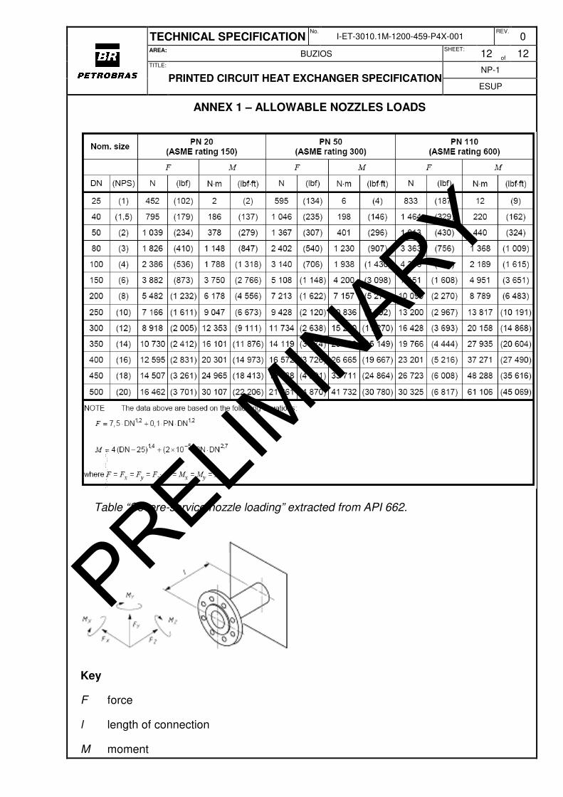
6.2.1 Nozzles shall be designed to accept the loads due to piping reaction shown in ANNEX 1. It shall be noted that with the listed standard nozzle loads, no heave, surge or sway combinations are implied.
6.2.2 All flange connections (nominal size and flange facing) shall comply with ASME Code.
6.2.3 When the use of compact flanges is specified for the equipment nozzles, the compact flange shall comply with NORSOK L-005.
PRELIMIN
ARY
TECHNICAL SPECIFICATION No.
I-ET-3010.1M-1200-459-P4X-001 REV.
0 AREA:
BUZIOS SHEET:
7 of 12
TITLE:
PRINTED CIRCUIT HEAT EXCHANGER SPECIFICATION NP-1
ESUP
6.2.3.1 For pressure classes not comprised in NORSOK L-005, the heat exchanger manufacturer shall use flanges similar to compact ones specified by NORSOK L-005 and the flange supplier shall be previously approved by PETROBRAS.
6.2.3.2 In any case the flange shall be designed by ASME VIII Div.2 Part 5.
6.3 Material Selection
MANUFACTURER shall refer to I-ET-3010.1M-1200-450-P4X-001 - MATERIAL SPECIFICATION FOR HEAT EXCHANGERS for the material selection of the printed circuit heat exchangers.
All materials that are exposed to hydrocarbons containing hydrogen sulphide must follow the requirements of ISO 15156 for sour service.
6.4 Welding & NDT
6.4.1 All welding and NDT (see 10.2.3) shall be performed in compliance with ASME Boiler and Pressure Vessel and API RP 582. All structural welding shall be in accordance with the structural welding code ASME AWS D1.1.
6.4.2 Only full penetration welds are permitted.
7 SURFACE PREPARATION AND PAINTING
7.1 All stainless steel exchanger areas exposed to the environment shall be sheathed with Duplex or Super Duplex material, as specified in the data sheets.
7.2 The paint system shall be according to I-ET-3010.00-1200-956-P4X-002 – GENERAL PAINTING.
7.3 Color code adopted shall shall comply with DR-ENGP-I-1.15 – COLOR CODING.
7.4 Duplex and Super Duplex parts shall be externally painted to avoid CSCC (chloride stress corrosion cracking) when the outer metal temperature is above 80°C for Duplex and above 90°C for Super Duplex.
8 NAMEPLATES AND SIGNS
8.1 MANUFACTURER shall weld a 3mm thick, SS 316 stainless steel nameplate on each equipment, in an accessible location.
8.2 The nameplate information shall include, as a minimum, the following in the Portuguese language:
• All Code and Classification requirements,
PRELIMIN
ARY

TECHNICAL SPECIFICATION No.
I-ET-3010.1M-1200-459-P4X-001 REV.
0 AREA:
BUZIOS SHEET:
8 of 12
TITLE:
PRINTED CIRCUIT HEAT EXCHANGER SPECIFICATION NP-1
ESUP
• Design code,
• Purchase order-number,
• Tag number,
• MANUFACTURER and year built,
• Equipment’s serial number and type,
• Design temperature and pressure,
• Maximum allowable working pressure;
• Minimum design metal temperature,
• Operating temperature and pressure,
• Thermal duty, volume, etc.,
• Hydrostatic test Pressure,
• Post weld heat treatment, if performed,
• Empty, operational and test weight,
• Service.
All technical data shall be shown in metric units, except for pressure which shall be indicated in ‘bar’.
8.3 The exchanger category according to NR-13 must be fitted in an additional nameplate next to the main nameplate.
8.4 All safety signs shall be in the Portuguese language.
9 CERTIFICATION REQUIREMENTS
9.1 For all heat exchangers, a Classification Society certificate shall be supplied. MANUFACTURER shall be responsible to obtaining all necessary certification of the equipment. MANUFACTURER through the independent certifying authority shall supply all certificates related to the materials, inspections, tests and qualification activities detailed in the approved Quality Plan.
PRELIMIN
ARY
TECHNICAL SPECIFICATION No.
I-ET-3010.1M-1200-459-P4X-001 REV.
0 AREA:
BUZIOS SHEET:
9 of 12
TITLE:
PRINTED CIRCUIT HEAT EXCHANGER SPECIFICATION NP-1
ESUP
10 INSPECTION, TESTING AND COMMISSIONING
10.1 Inspection
10.1.1 MANUFACTURER shall submit an Inspection and Test Plan (ITP) based on the technical data sheet with witnessed inspections and tests identified.
10.1.2 MANUFACTURER shall ensure that all the witnessed inspection requirements by the Classification Society are fully accommodated and the due notice requirements are satisfied.
10.1.3 The notification period for such inspections shall be mutually agreed.
10.1.4 Before shipment the equipment shall be subject to a final inspection witnessed by PETROBRAS.
10.2 Testing
10.2.1 See ASME Code for hydrostatic test and for the minimum extent of non destructive examination of welds on core block, headers and nozzles.
10.2.2 Before the hydrostatic test, a leak test with gaseous fluid shall be performed at a pressure not exceeding the design pressure. The testing methodology and acceptance criteria shall be agreed upon between PETROBRAS and the equipment MANUFACTURER using ASME code Section V as a basis.
10.2.3 The following NDT shall be carried out:
• Visual examination:
100% welds must be subjected to a visual inspection, internal and externally.
• Dye penetrant testing to ASME V Art. 6.
100% root welds.
100% final capping welds.
100% lifting attachments.
• Ultrasonic testing to ASME V Art. 5
100% of 50 mm wide band around all cut openings for set on nozzles.
• Radiography to ASME V Art. 2.
100% nozzle longitudinal butt welds.
100% flange to nozzle butt welds
PRELIMIN
ARY
TECHNICAL SPECIFICATION No.
I-ET-3010.1M-1200-459-P4X-001 REV.
0 AREA:
BUZIOS SHEET:
10 of 12
TITLE:
PRINTED CIRCUIT HEAT EXCHANGER SPECIFICATION NP-1
ESUP
100% header circumferential welds.
100% longitudinal header to block welds where access permits.
• Positive materials identification (PMI), required as indicated below:
100% of all pressure retaining parts.
Note: The PMI shall be carried out with equipment capable to identify the specified type of material in accordance with established procedure. The equipment shall not make burn marks to the material. The PMI shall be done prior the welding to identify the materials which will be welded, but after diffusion bonding of exchanger cores.
10.3 Commissioning
10.3.1 MANUFACTURER will be required to provide any necessary support for installation and commissioning of the equipment at the construction yard or offshore.
11 PREPARATION FOR SHIPMENT
11.1 Marking
11.1.1 All items supplied to this specification shall be adequately marked for identification against a certificate or relevant test documentation. Marking shall be such that it will not damage or impair the component.
11.1.2 Items that cannot be identified shall be rejected. Rejected items may be re-certified by carrying out all relevant testing, with previous approval of PETROBRAS.
11.1.3 As a minimum, the following identification shall be provided:
• Project Number
• MANUFACTURER’s name
• Purchase Order Number
• Minimum Breaking Load (MBL)
• Item Number
• Classification Society surveyor’s stamp
11.2 Shipment Packing
PRELIMIN
ARY

TECHNICAL SPECIFICATION No.
I-ET-3010.1M-1200-459-P4X-001 REV.
0 AREA:
BUZIOS SHEET:
11 of 12
TITLE:
PRINTED CIRCUIT HEAT EXCHANGER SPECIFICATION NP-1
ESUP
11.2.1 The equipment shall be suitably prepared for the type of shipment specified. The preparation shall make the equipment suitable for 12 months of outdoor storage from time of shipment.
11.2.2 MANUFACTURER shall submit the packing design to PETROBRAS for approval. MANUFACTURER shall package the equipment in accordance with the packaging requirements of the country to which the equipment is being shipped. The package must be protected from corrosion.
11.2.3 MANUFACTURER shall provide the procedures for unpacking, handling and installation, as well as repacking, and long-term storage requirements. MANUFACTURER shall specify any limitations applicable to the transport and installation phase.
PRELIMIN
ARY
TECHNICAL SPECIFICATION No.
I-ET-3010.1M-1200-459-P4X-001 REV.
0 AREA:
BUZIOS SHEET:
12 of 12
TITLE:
PRINTED CIRCUIT HEAT EXCHANGER SPECIFICATION NP-1
ESUP
ANNEX 1 – ALLOWABLE NOZZLES LOADS
Table “Severe-service nozzle loading” extracted from API 662.
Key
F force
l length of connection
M moment
PRELIMIN
ARY