Embed Size (px)
Citation preview
International Journal of Solids and Structures 49 (2012) 2962–2977
Contents lists available at SciVerse ScienceDirect
International Journal of Solids and Structures
journal homepage: www.elsevier .com/locate / i jsolst r
Indentation of an elastic layer by a rigid cylinder
J.A. Greenwood a,⇑, J.R. Barber b
a University Engineering Department, Cambridge, UKb Department of Mechanical Engineering, University of Michigan, USA
a r t i c l e i n f o a b s t r a c t
Article history:Received 6 October 2011Received in revised form 27 March 2012Available online 12 June 2012
Keywords:Green’s functionIndentationElastic layer
0020-7683/$ - see front matter � 2012 Elsevier Ltd. Ahttp://dx.doi.org/10.1016/j.ijsolstr.2012.05.036
⇑ Corresponding author.E-mail address: [email protected] (J.A. Greenwoo
The Green’s functions for the indentation of an elastic layer resting on or bonded to a rigid base by a lineload are found efficiently and accurately by a combination of contour integration with a series expansionfor small arguments. From the form of the equations it is clear that the function is oscillatory when thelayer is free to slip over the base, but for the bonded layer, the function simply decays to zero after a sin-gle overshoot.
The deformation due to pressure distributions of the form of the product of a polynomial with an ellip-tical (‘‘Hertzian’’) term is calculated and the coefficients chosen to match the indentation shape to that ofa cylindrical indenter. The resulting pressure distributions behave much as in Johnson’s approximate the-ory, becoming parabolic instead of elliptical as the ratio b/d of contact width to layer thickness increases,or, for the bonded incompressible (m = 1/2) layer, becoming bell-shaped for very large b/d.
The relation between the approach d and the contact width b curves has been investigated, and someanomalies in published asymptotic equations noted and, perhaps, resolved.
A noticeable feature of our method is that, unlike previous solutions in which the full mixed boundaryvalue problem (given indenter shape / stress-free boundary) has been solved, the bonded incompressiblesolid causes no problems and is handled just as for lower values of Poisson’s ratio.
� 2012 Elsevier Ltd. All rights reserved.
1. Introduction
The indentation of a layer by a rigid circular cylinder is of sometechnological importance, as is evidenced by the origins of theearly papers: Hannah (1951) in the Department of TextileIndustries (University of Leeds), Miller (1966) from the Printing,Packaging and Allied Trades Research Association. Sadly, neitherMeijers (1968) nor, particularly Aleksandrov’s contributions (e.g.Aleksandrov (1969)) are easy for an engineer to understand: asituation perhaps explained by Alblas and Kuiper’s comment(1970). ‘‘We find it difficult to trace the effects [of the two approx-imations] separately and do not see beforehand whether the twoapproximations are compatible’’. Here a relatively simple-mindedapproach is adopted: we avoid the mixed boundary value problemby finding the solution for a point load (the Green’s function) anduse this to obtain the indentation shape for a pressure distributionp ¼
ffiffiffiffiffiffiffiffiffiffiffiffiffi1� t2p P
ðent2nÞ where t = x/b and b is the half-width of thecontact. The coefficients en are then chosen to approximate thedesired indentation shape. The resulting fits appear to beexcellent.
The elegant feature of this analysis is the use of contour integra-tion to evaluate the integral for the Green’s function, as introduced
ll rights reserved.
d).
by Dougall (1904) but rejected by later authors (e.g. Sneddon,1946) because of the difficulty at the time in performing complexarithmetic. This is no longer a problem: and in practice over muchof the range needed it is found that the Green’s function is in effectonly a single damped exponential term.
2. Green’s function for an elastic layer resting on a rigid base
We consider first a layer resting on a rigid, frictionless base, i.e.with no normal displacement or shear stress at its base. A line loadp(x) = d(x) can be represented by its Fourier integralpðxÞ ¼ 1
p
R10 cosðkxÞdk. For a layer of thickness d with no displace-
ment or shear stress at its base (or a symmetrically loaded layerof thickness 2d), the surface displacement due to p1cos(kx) is.
E0wðxÞ ¼ 2p1
ksinh2ðaÞ
sinhðaÞ coshðaÞ þ acosðkxÞ where a = kd and E0 is
the plane strain modulus E/(1 � m2). Hence, the displacementw(x) due to a unit line load at x = 0 is w(x) = Y(n)/E0, where n = x/dand
YðnÞ ¼ 2p
Z 1
0
sinh2ðaÞsinhðaÞ coshðaÞ þ a
cosðanÞdaa
ð1Þ
[Hannah (1951): see also Johnson, 1985 Eq. 5.65, but beware of theone-sided Fourier transform (Eq. 5.66)].
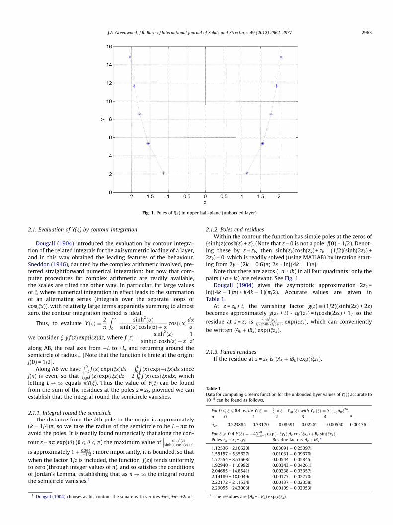
Fig. 1. Poles of f(z) in upper half-plane (unbonded layer).
Table 1Data for computing Green’s function for the unbonded layer values of Y(n) accurate to10�5 can be found as follows.
For 0 6 n 6 0.4, write YðnÞ ¼ � 2p ln nþ YmðnÞ with YmðnÞ ¼
P5n¼0ann2n .
n 0 1 2 3 4 5
a2n �0.223884 0.33170 �0.08591 0.02201 �0.00550 0.00136
For n P 0:4;YðnÞ ¼ �4P8
k¼1 expð�nykÞ½Ak cosðnxkÞ þ Bk sinðnxkÞ�Poles zk � xk + iyk Residue factors Ak þ iBk
a
1.12536 + 2.10620i 0.03091 � 0.25397i1.55157 + 5.35627i 0.01031 � 0.09370i1.77554 + 8.53668i 0.00544 � 0.05845i1.92940 + 11.6992i 0.00343 � 0.04261i2.04685 + 14.8541i 0.00238 � 0.03357i2.14189 + 18.0049i 0.00177 � 0.02770i2.22172 + 21.1534i 0.00137 � 0.02358i
J.A. Greenwood, J.R. Barber / International Journal of Solids and Structures 49 (2012) 2962–2977 2963
2.1. Evaluation of Y(n) by contour integration
Dougall (1904) introduced the evaluation by contour integra-tion of the related integrals for the axisymmetric loading of a layer,and in this way obtained the leading features of the behaviour.Sneddon (1946), daunted by the complex arithmetic involved, pre-ferred straightforward numerical integration: but now that com-puter procedures for complex arithmetic are readily available,the scales are tilted the other way. In particular, for large valuesof n, where numerical integration in effect leads to the summationof an alternating series (integrals over the separate loops ofcos(nx)), with relatively large terms apparently summing to almostzero, the contour integration method is ideal.
Thus, to evaluate YðnÞ ¼ 2p
Z 1
0
sinh2ðaÞsinhðaÞ coshðaÞ þ a
cosðnaÞdaa
we consider 2p
Hf ðzÞ expðinzÞdz, where f ðzÞ � sinh2ðzÞ
sinhðzÞ coshðzÞ þ z� 1
z,
along AB, the real axis from �L to +L, and returning around thesemicircle of radius L. [Note that the function is finite at the origin:f(0) = 1/2].
Along AB we haveR 0�L f ðxÞ expðinxÞdx ¼
R L0 f ðxÞ expð�inxÞdx since
f(x) is even, so thatR
AB f ðzÞ expðinzÞdz ¼ 2R L
0 f ðxÞ cosðnxÞdx, whichletting L ?1 equals pY(n). Thus the value of Y(n) can be foundfrom the sum of the residues at the poles z = zk, provided we canestablish that the integral round the semicircle vanishes.
2.1.1. Integral round the semicircleThe distance from the kth pole to the origin is approximately
(k � 1/4)p, so we take the radius of the semicircle to be L = np toavoid the poles. It is readily found numerically that along the con-
tour z = np exp(ih) (0 6 h 6 p) the maximum value of sinh2ðzÞsinhðzÞ coshðzÞþz
��� ���is approximately 1þ 0:264
nþ1=2 : more importantly, it is bounded, so that
when the factor 1/z is included, the function jf(z)j tends uniformlyto zero (through integer values of n), and so satisfies the conditionsof Jordan’s Lemma, establishing that as n ?1 the integral roundthe semicircle vanishes.1
1 Dougall (1904) chooses as his contour the square with vertices ±np, ±np +2npi.
2.1.2. Poles and residuesWithin the contour the function has simple poles at the zeros of
{sinh(z)cosh(z) + z}. (Note that z = 0 is not a pole: f(0) = 1/2). Denot-ing these by z = zk, then sinh(zk)cosh(zk) + zk � (1/2)(sinh(2zk) +2zk) = 0, which is readily solved (using MATLAB) by iteration start-ing from 2y = (2k � 0.6)p; 2x = ln{(4k � 1)p}.
Note that there are zeros (±a ± ib) in all four quadrants: only thepairs (±a + ib) are relevant. See Fig. 1.
Dougall (1904) gives the asymptotic approximation 2zk =ln((4k � 1)p) + i(4k � 1)(p/2). Accurate values are given inTable 1.
At z = zk + t, the vanishing factor g(z) � (1/2)(sinh(2z) + 2z)becomes approximately g(zk + t) � tg0(zk) = t{cosh(2zk) + 1} so the
residue at z = zk is sinh2ðzkÞzkfcoshð2zkÞþ1g expðinzkÞ, which can conveniently
be written ðAk þ iBkÞ expðinzkÞ.
2.1.3. Paired residuesIf the residue at z = zk is ðAk þ iBkÞ expðinzkÞ.
2.29055 + 24.3003i 0.00109 � 0.02053i
a The residues are (Ak + i Bk) exp(inzk).

Fig. 2. (a) Green’s function, showing mildly oscillatory behaviour at large n. (b) Green’s function showing oscillatory behaviour in detail. The spots are the values using onlythe contribution from the first pair of poles.
2964 J.A. Greenwood, J.R. Barber / International Journal of Solids and Structures 49 (2012) 2962–2977
Since the residue at z = zk is ðAk þ iBkÞ expðinzkÞ, the residue at thematching pole z ¼ ��zk will be �ðAk þ iBkÞ expðin�zkÞ, so that for n = 0the sum of the two residues is 2i Bk. For n – 0, the residues are (Ak + iBk)exp(�nyk)(cos(nxk) + isin(nxk)) and (�Ak + i Bk)exp(�nyk)(cos(nxk) � isin(nxk)), so adding gives 2iexp(�nyk)(Aksinnxk + Bkcos(nxk) � 2i Imag[f(zk) exp(inzk)].
Multiplying the sum of the residues by 2pi gives pY(n).The results agree beautifully with values previously found by a
numerical integration, but now establish clearly the behaviour ofthe Green’s function at large n. The results are shown in Fig. 2a,and exhibit a mildly oscillatory behaviour at large n shown in thetwo insets. The leading term is that due to the residues at the firstpair of poles z = (±x1 + i y1) giving the asymptotic result
YðnÞ � 4expð�2:1062nÞ½0:2540cosð1:1254nÞ�0:0309sinð1:1254nÞ�:
As Fig. 2b shows, this is already a good approximation when n = 1.The evaluation of Y(n) as the sum of the residues requires more
and more terms as n decreases, reflecting the fact that the Green’sfunction Y(n) will be logarithmically singular near the point ofapplication of the force x = 0. This behaviour is determined bythe behaviour of the integrand at large a, where
sinh2ðaÞsinhðaÞ coshðaÞþa � tanhðaÞ. In order to extract the singular term analyt-
ically, we therefore write f ðaÞ � sinh2ðaÞsinhðaÞ coshðaÞþa ¼ f1ðaÞ � f2ðaÞ where
f1(a) = tanh(a) and f2ðaÞ ¼ tanhðaÞ � f ðaÞ ¼ a tanhðaÞsinhðaÞ coshðaÞþa.
Now using Gradstein and Rhyzik 4.114.2 we have
Z 1
0tanhðaÞ cosðanÞda
a¼ 1
2ln
coshðpn=2Þ þ 1coshðpn=2Þ � 1
� �
¼ lnfcothðpn=4Þg
and hence we can write Y(n) = Y1(n) � Y2(n) with Y1ðnÞ ¼ � 2p
lnftanhðpn=4Þg and the residual term
Y2ðnÞ ¼2p
Z 1
0f2ðaÞ cosðanÞda
a
¼ 2p
Z 1
0
tanhðaÞsinhðaÞ coshðaÞ þ a
cosðanÞda ð3Þ
is bounded for all nSince the series for cosu is uniformly convergent, we can expand
the cosine in series and integrate term by term: this is convenient
for small values of n (n 6 0.5). [Over a substantial range bothmethods give the same answers (agreeing to 10�5): cf Fig. 9 belowfor the bonded layer].
2.2. Green’s function over the whole range
The contour integration equations were used to give values ofthe Green’s function for n P 0.4. The series expansion was usedto give values of YðnÞ þ 2
p lnftanhðpn=4Þg for n < 0.4. [The change-over point is largely arbitrary because of the extensive overlaprange]. For further work it was convenient to introduce an auxil-iary function YmðnÞ � YðnÞ þ 2
p lnðnÞ shown in Fig. 3. This isbounded at n = 0 and convenient for numerical work while thelogarithmic term can be treated analytically (see Appendix C).Table 1 gives the coefficients needed to determine the Green’sfunction Y(n) over the entire range.
3. Pressure distribution under a roller
It is generally accepted in roller bearing calculations that the
Hertzian pressure distribution, p ¼ ðE�=2RÞffiffiffiffiffiffiffiffiffiffiffiffiffiffiffiffib2 � x2
p, exact for con-
tact between a rigid parabolic indenter and an elastic half-space, isa good approximation to the pressure between a roller and a finitelayer (Johnson, 1985). Johnson however assumes the layer thick-ness d (or more precisely the ratio d/b) to be large. When d/b isnot large, it is clear that a pressure distribution consisting of aproduct of a power series with the Hertzian pressure is likely tobe better: so we need to calculate the indentation shape for pres-sures of this form.
The displacements w(x) will be
E0wðxÞ ¼Z þb
�bpðx0ÞYðjx� x0j=dÞdx0
¼ bZ þ1
�1pðt0ÞYfðb=dÞjt � t0jgdt0 ð4Þ
As noted above, the logarithmic singularity in the function Y(n) isextracted by writing YðnÞ � YmðnÞ � 2
p lnðnÞ.
3.1. Integration to find the shape
If the pressures pðxÞ ¼ffiffiffiffiffiffiffiffiffiffiffiffiffiffiffiffiffiffiffiffiffi1� x2=b2
q Penx2n are written in the
Chebyshev form pðcos hÞ ¼ sin hP
cn cos 2nh where t � x/b = cosh,the integration of the singular term may be done analytically

Fig. 3. Non-singular part of the Green’s function for a layer of thickness d. To obtain the Green’s function Y(x/d) a term (2/p) ln (x/d) must be subtracted.
Fig. 4. Matching of shapes of surface and indenter. The shape found is very close to the cylindrical shape desired. Additional terms have little effect.
J.A. Greenwood, J.R. Barber / International Journal of Solids and Structures 49 (2012) 2962–2977 2965
(see Appendix C) and leads to displacements within the indenta-tion of the form wðx=bÞ ¼
PCm cosð2m/Þ where x = bcos/.
These can easily converted into a power series in x2.The non-singular part of the Green’s function, Ym(n) is readily
integrated numerically.The shape coefficients c0,c2, . . . are now chosen to give a shape
approximating the indenter shape. The shapes due to the individ-ual pressure terms were curve-fitted to polynomials in x2 (of order6) and the coefficients c0,c2, . . . chosen to eliminate the terms in
x4,x6 . . .x12 and leave just z = x2/2 with excellent results: Fig. 3shows the fit for an extreme case, b/d = 10 and Fig. 4 shows thecorresponding pressure distribution. [The inclusion of termsT8,T10, . . . improves the fit near x = b but otherwise has littleeffect].
The calculated pressure distributions are close to the elliptical‘Hertzian’ pressures for b/d6 1 (very close for b/d < 0.5), but approachthe parabolic shape predicted by Johnson (1985) for b/d large. Themaximum pressure agrees with his prediction that asymptotically

Fig. 5. Development of pressure distribution as b/d increases.
Fig. 6. Displacement for an unbonded layer of thickness d. Note that for b/d small, the result may be written Rd = 0.5b2[ln (2.320d/b)].
2966 J.A. Greenwood, J.R. Barber / International Journal of Solids and Structures 49 (2012) 2962–2977
Rpmax/E0b � b/2d but with a small offset [b/2d + 0.183] (see Fig. 16below).
3.2. Displacement
The displacement at x = 0, (the compliance, or approach), isfound from the shape integration by setting x = 0 (/ = p/2). Theresults are shown in Fig. 6, where it is seen that the simple asymp-tote Rd = 0.5b2(ln(2.320 d/b)) is good up to b/d � 0.2. Above this,calculating the displacement due to a Hertzian pressure distribu-
tion p ¼ ðE�=2RÞffiffiffiffiffiffiffiffiffiffiffiffiffiffiffiffib2 � x2
pis little better than simply using the
asymptote. Examination shows that a pressure of the form
p ¼ Kffiffiffiffiffiffiffiffiffiffiffiffiffiffiffiffiffiffiffiffiffi1� x2=b2
qcan give a reasonable answer, but only if the com-
plete shape is calculated and the pressure then scaled to give thebest fit to the indenter shape z = x2/2R. In this way, good resultsare obtained up to b/d = 1: subsequently it seems Rd/b2 � 0.6 ratherthan the correct Rd/b2 ? 0.5 (Fig. 6).
It may be thought that the ordinate chosen, Rd/b2 is somewhatesoteric: why the interest in comparing indentations of the samewidth in layers of different thicknesses? The primary reason isindeed the authors’ dislike of graphs with answers ranging over104 as would the more natural Rd/d2. However, it may be noted
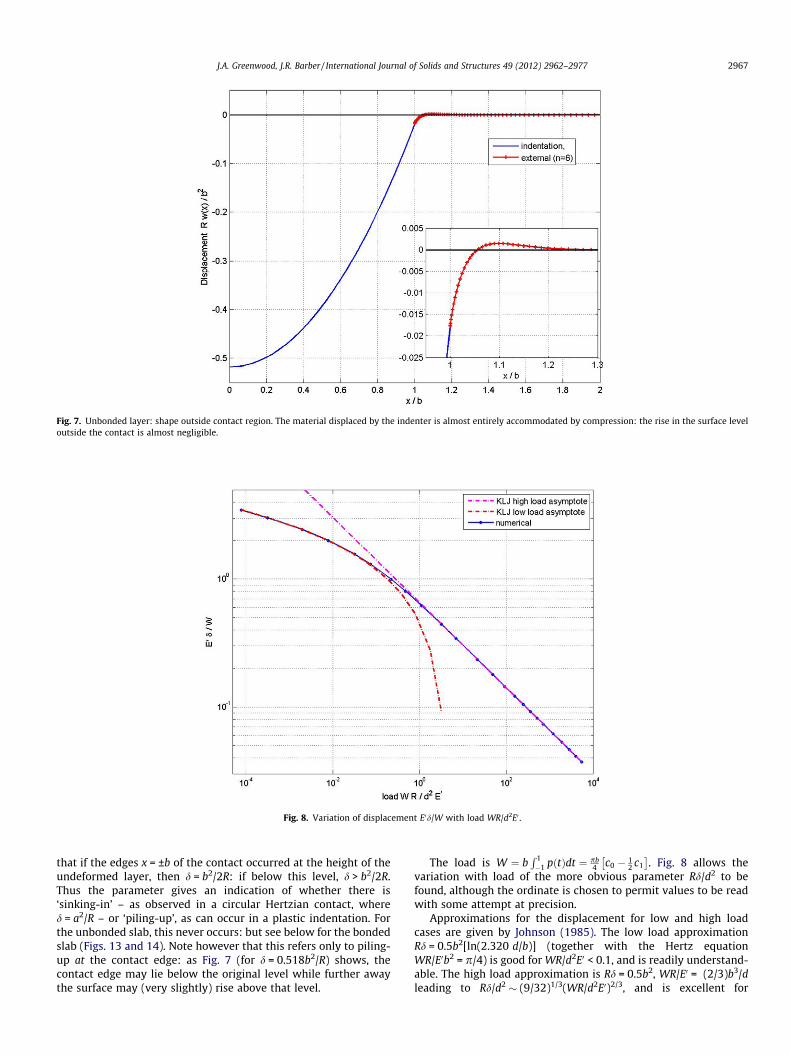
Fig. 7. Unbonded layer: shape outside contact region. The material displaced by the indenter is almost entirely accommodated by compression: the rise in the surface leveloutside the contact is almost negligible.
Fig. 8. Variation of displacement E0d/W with load WR/d2E0 .
J.A. Greenwood, J.R. Barber / International Journal of Solids and Structures 49 (2012) 2962–2977 2967
that if the edges x = ±b of the contact occurred at the height of theundeformed layer, then d = b2/2R: if below this level, d > b2/2R.Thus the parameter gives an indication of whether there is‘sinking-in’ – as observed in a circular Hertzian contact, whered = a2/R – or ‘piling-up’, as can occur in a plastic indentation. Forthe unbonded slab, this never occurs: but see below for the bondedslab (Figs. 13 and 14). Note however that this refers only to piling-up at the contact edge: as Fig. 7 (for d = 0.518b2/R) shows, thecontact edge may lie below the original level while further awaythe surface may (very slightly) rise above that level.
The load is W ¼ bR 1�1 pðtÞdt ¼ pb
4 c0 � 12 c1
� �. Fig. 8 allows the
variation with load of the more obvious parameter Rd/d2 to befound, although the ordinate is chosen to permit values to be readwith some attempt at precision.
Approximations for the displacement for low and high loadcases are given by Johnson (1985). The low load approximationRd = 0.5b2[ln(2.320 d/b)] (together with the Hertz equationWR/E0b2 = p/4) is good for WR/d2E0 < 0.1, and is readily understand-able. The high load approximation is Rd = 0.5b2, WR/E0 = (2/3)b3/dleading to Rd/d2 � (9/32)1/3(WR/d2E0)2/3, and is excellent for

Fig. 9. Green’s function for a bonded layer of incompressible solid. By using 40 poles contour integration can be used down to n = 0.04 (retaining 10�5 accuracy): by using 6terms the power series may be used up to n = 1: clearly each has its useful range, but there is a very considerable overlap region.
Fig. 10. Approach for low values of Poisson’s ratio. Rd/b2 falls steadily to the asymptotic value 0.5, indicating that the contact edge is then at the undisturbed height.
2968 J.A. Greenwood, J.R. Barber / International Journal of Solids and Structures 49 (2012) 2962–2977
WR/d2E0 > 1. This is somewhat surprising, for as Fig. 6 shows, Rd/b2
falls rather slowly to 0.5, and the pressure distribution is slow toattain the parabolic form assumed in the approximation.
4. Layer bonded to a rigid base
The more important case technologically is of an elastic layerbonded to a rigid base. This has been investigated in detail. (Han-nah, Miller, Meijers) but in searching for a mathematically exact
solution of the mixed boundary value problem (shape prescribedfor jxj < b, zero pressure for jxj > b, difficult analysis has resulted.In particular, it seems that the case of the incompressible materialm = 1/2 causes problems: indeed, even in Johnson’s elementaryanalysis of the problem, the incompressible solid needs a separateanalysis. By attempting to obtain only an approximate solution(but it seems probable, cf Fig. 4 above and many tests for thebonded layer, that the accuracy is high), none of these problemsarise.

Fig. 11. Approach for m = 0.4 (Indenter shape fitted using 6 Chebyshev polynomials). A sign has been arbitrarily changed in the Alblas asymptote, see below.
Fig. 12. Approach for incompressible and almost incompressible solids.
2 exp(�k(m)n) with k = 1.19, 1.09, 1.00, 0.91, 0.83, 0.74 for m = 0, 0.1, 0.2, 0.3, 0.4, 0.5
J.A. Greenwood, J.R. Barber / International Journal of Solids and Structures 49 (2012) 2962–2977 2969
Hannah (1951) shows that the Green’s function is now
YðnÞ ¼ 2p
Z 1
0
K1 sinhð2aÞ � 2aK1 coshð2aÞ þ 2a2 þ K2
cosðanÞdaa
where K1 = 3 � 4m; K2 = K1 + 2(1 � 2m)2.The analysis follows exactly the same path as for the unbonded
cylinder, with a solution for large n found by contour integrationand a power series solution for small n. There is again a large rangewhen the two solutions overlap and give the same results. The de-tails are given in Appendix A.
The dominant term for n > 1 comes from the pole on the imag-inary axis, so has no oscillatory component. The decay rate is
O(e�kn) with k � 12 compared with O(e�2.1n) for the unbonded layer,so the significant range of the Green’s function is much greater.
4.1. Indentation by a cylinder
The analysis now follows exactly the same procedure as for theunbonded layer. The results shown in Fig. 10 are typical for allm 6 0.3: and resemble those for the unbonded layer.
For Poisson’s ratio less than 0.3, the shape outside the indenta-tion is very similar to that for the unbonded layer, with negligible
.

Table 2Data for computing Green’s function for the bonded layer.
(a) Bonded layer 0 6 n 6 0.4
YðnÞ ¼ � 2p lnðtanhðpn=8Þ þ YbðnÞ: YbðnÞ ¼
P5n¼0bnn2n
n 0 1 2 3 4 5
m = 0.3 bn 0.93032 �0.42308 0.15492 �0.05090 0.01563 �0.00460m = 0.4 bn 1.02985 �0.49437 0.18863 �0.06348 0.01974 �0.00584m = 0.49 bn 1.19194 �0.60268 0.24027 �0.08300 0.02616 �0.00780m = 0.5 bn 1.21667 �0.61892 0.24813 �0.08602 0.02716 �0.00810
(b) n > 4 YðnÞ ¼ �4P8
k¼1 expð�n ykÞ½Ak cosðn xkÞ þ Bk sinðnxkÞ�
Poles zk � xk + iyk Residue factors Ak + iBk�
Bonded layer m = 0.30.00000 0.91278i 0.00000 0.01285i1.45379 2.57039i �0.01768 �0.25010i2.23310 5.91308i 0.00555 �0.08875i2.64719 9.13968i 0.00440 �0.05561i2.93600 12.33113i 0.00326 �0.04080i3.15887 15.50616i 0.00249 �0.03231i3.34065 18.67200i 0.00196 �0.02678i3.49425 21.83210i 0.00159 �0.02289i
Bonded layer m = 0.4
0.00000 0.82631i 0.00000 0.05108i1.60943 2.53750i 0.00220 �0.24495i2.36711 5.89487i 0.00784 �0.08842i2.77705 9.12713i 0.00524 �0.05550i3.06423 12.32154i 0.00370 �0.04075i3.28629 15.49842i 0.00276 �0.03228i3.46759 18.66550i 0.00215 �0.02676i3.62089 21.82651i 0.00172 �0.02287i
Bonded layer m = 0.49
0.00000 0.74790i 0.00000 0.12108i1.78628 2.49302i 0.02314 �0.24021i2.52422 5.87255i 0.01044 �0.08801i2.93001 9.11200i 0.00622 �0.05536i3.21555 12.31008i 0.00422 �0.04068i3.43677 15.48918i 0.00308 �0.03224i3.61758 18.65777i 0.00236 �0.02674i3.77057 21.81986i 0.00188 �0.02285i
Bonded layer m = 0.5
0.00000 0.73909i 0.00000 0.13193i1.80936 2.48689i 0.02579 �0.23957i2.54489 5.86956i 0.01077 �0.08795i2.95017 9.10999i 0.00635 �0.05534i3.23550 12.30856i 0.00428 �0.04067i3.45661 15.48796i 0.00312 �0.03224i3.63737 18.65675i 0.00239 �0.02673i3.79031 21.81898i 0.00190 �0.02285i
� The residues are (Ak + iBk) exp(inzk).
Table 3Meijers and Alblas asymptotic results.
m Rd/b2 (Alblas) Rd/b2 (Meijers (deduced))
U 0.5 + 0.170(d/b) + 0.029(d/b)2
0 0.5 + 0.176(d/b) � 0.016(d/b)2
d/b < 10.5 + 0.1831(d/b) + 0.0168(d/b)2
0.2 0.5 + 0.173(d/b) � 0.001(d/b)2
d/b < 10.3 0.5 + 0.115(d/b) � 0.042(d/b)2
d/b < 0.450.5 + 0.1221(d/b) + 0.0432(d/b)2
0.4 0.5 � 0.118(d/b) � 0.340(d/b)2
d/b < 0.250.5 � 0.1113(d/b) + 0.3395(d/b)2
0.45 0.5 � 0.5487(d/b) + 1.2415(d/b)2
0.48 0.5 � 1.5318(d/b) + 4.7117(d/b)2
0.5 1þ4:358ðd=bÞþ0:9307ðd=bÞ2þ0:098ðd=bÞ36ð1þ1:4526ðd=bÞ
1þ4:3772ðd=bÞþ0:9868ðd=bÞ2þ0:1041ðd=bÞ36ð1þ1:4591ðd=bÞ
U = Unbonded layerIn Meijers equations, terms a0exp(�2A b/d) have been ignored since a0 is not given.For comparison, our results for (m = 0.4) are fitted by [0.5 �0.1198+0.3797] (b/
d = 4:20).
2970 J.A. Greenwood, J.R. Barber / International Journal of Solids and Structures 49 (2012) 2962–2977
pile-up. However, Fig. 11 shows that for m = 0.4 a new featureoccurs: instead of Rd/b2 decreasing steadily to 0.5, it overshootsbefore rising to the asymptotic value. An immediate reaction isthat this is absurd, but comparison with asymptotes produced byMeijers (1968) and Alblas and Kuipers (1970) suggests that it isat least qualitatively correct.
The negative coefficient of (d/b)2 given by Alblas for the asymp-tote (for all values of m 6 0.4) gives implausibly low values whenm = 0.4 for b/d < 10 (although the equation is said to be valid forall b/d P 4); and has arbitrarily been reversed for plotting Fig. 11(see discussion): with this done, both asymptotes are close to thevalues found by the present method.
Results for larger values of m repeat the pattern, with somewhatlower minimum values. Only for m = 0.5 is the behaviour different.As shown in Fig. 12, the incompressible solid follows the samepattern of the minimum of Rd/b2 steadily decreasing as m increases,except that here the minimum may well be at infinity, with thevalue 1/6 as predicted by Meijers. For this case, numerical values

Fig. 13. (a) Bonded layer, as m ? 0.5. (b) Incompressible solid: results for moderate b/d. The curves are identical to those given by Miller (Fig. 8). The pile-up nowaccommodates all the volume of the indentation.
Fig. 14. Bonded layer showing effect of layer thickness.
J.A. Greenwood, J.R. Barber / International Journal of Solids and Structures 49 (2012) 2962–2977 2971
from the Alblas & Kuiper asymptote are almost indistinguishablefrom those from Meijers’ equation (see Table 3): and the agree-ment with our results appears to be perfect.
4.1.1. Asymptotic behaviour for small b/dThe linear decrease of Rd/b2 as 0.5ln(d/b) is common to all values of
m (and for the unbonded layer); but the curves are not the same, beingoffset by an amount dependent on m: so Rd/b2 � 0.5ln(d/b) + a(m).Values of a(m) may be found from the values of b0 given in Table 2according to a(m) = (1/4)[1 + 2ln (16/p) � pb0]: but no simpleequation for a(m) or b0 has been found. Argatov (2001) shows thataðmÞ ¼ 0:5ð1þ lnð2ÞÞ þ
R10 ð1� e�a � LðaÞÞda=a where LðaÞ �
K1 sinhð2aÞ�2aK1 coshð2aÞþ2a2þK2
(or the corresponding function for the unbonded
layer): values calculated from this integral are in excellent agreement
with the values found here. An empirical fit (with a maximum error of0.2% for 06 m6 0.5 is a(m) � (0.41� 0.5678m � 0.34m2)/(1 � 1.24m).For comparison, the unbonded layer has a = 0.5ln(2.320) = 0.4208.
4.1.2. Shape outside the indentationThe most convenient way to obtain the external shape is the di-
rect numerical integration of the complete Green’s function Y(n)since this is negligible whenever n is large. However it is not easyto obtain accurate values when x/b is close to 1, so there the loga-rithmic term was again subtracted and integrated analytically (seeAppendix C) and numerical integration performed on the reducedfunction Ym(n). Values of Rd/b2 approaching 1/2 suggest a ratherdifferent shape for the indentation from that shown in Fig. 7 forthe unbonded layer. Fig. 13 shows examples of the behaviour, ob-served in less extreme form for values of Poisson’s ratio exceeding

Fig. 15. Development of pressure distribution: bonded, incompressible layer.
Fig. 16. Maximum pressure for unbonded and bonded layers. The slopes agree well with Johnson’s asymptotic values.
2972 J.A. Greenwood, J.R. Barber / International Journal of Solids and Structures 49 (2012) 2962–2977
perhaps 0.4. For the bonded, incompressible solid the volume ofthe pile-up must of course equal the volume of the indentation:the rather limited lateral extent guarantees the greater height. AsMeijers points out, for large b/d when Rd/b2 � 1/6, the height ofthe pile-up will be twice the indentation depth.
As b/d increases, more and more of the displaced material isaccommodated by compression, and the pile-up at the edge ofthe indentation decreases.
4.1.3. Pressure distributionsFor moderate or small values of Poisson’s ratio, the development
of the pressure distribution as b/d increases is very much as for the
unbonded layer Fig. 5, starting with the Hertzian distribution forb/d 6 0.5 (initially with the Hertzian maximum pressurep0 = (E0b/2R) but then with the maximum increasing), and approach-ing Johnson’s limiting parabolic distribution closely for b/d P 10.
In contrast, for the incompressible layer, a quasi-parabolic dis-tribution is reached for b/d � 5 (Fig. 15), but the development con-tinues, apparently approaching Johnson’s second limit, p /(1 � x2)2 at the limit of our calculations. (Our arbitrary limit of 6terms of the pressure series restricted us to b/d up to 30).
The maximum pressures agreed well with Johnson’s linearasymptote Rpmax/bE0 � C(m) � (b/d) with C(m) = (1 � m)2/(2(1 � 2m))for m 6 0.45 but with an offset (see Fig. 16), and qualitatively with

Fig. 17. Comparison of Meijers and Alblas asymptotes. Changing the signs of the Alblas quadratic coefficients results in good agreement between the two.
Fig. 18. Location at which interface pressure becomes negative.
J.A. Greenwood, J.R. Barber / International Journal of Solids and Structures 49 (2012) 2962–2977 2973
his result for m = 0.5 [Rpmax/bE0 � (1/24) � (b/d)3]. For 0.45 < m < 0.5the initial curvature persisted to higher values of b/d, and it wasnot possible to determine a slope.
5. Discussion: asymptotes and accuracy
For the incompressible solid (m = 0.5), Meijers and Alblas give al-most identical asymptotes, and the agreement between these andthe present results appears perfect. This confirms the accuracy ofour numerical procedure: and since it applies without any notice-able changes to all values of Poisson’s ratio, suggests to us that allour results are trustworthy.
In contrast, while the analyses by Meijers and Alblas each leadto a simple quadratic in (d/b) (instead of a rational function asfound for m = 0.5), the two asymptotes have a glaring differencein the sign of the coefficient of (d/b)2: Alblas throughout givingnegative values, Meijers positive values. Of the cases given by bothauthors, the quadratic coefficients are small and the resulting dif-ferences in Rd/b2 are unimportant except for m = 0.4, for which Al-blas gives
Rd
b2 � 0:5� 0:118ðd=bÞ � 0:349ðd=bÞ2 ðm ¼ 0:4Þ

Fig. 19. Restrictions on indenter radius.
2974 J.A. Greenwood, J.R. Barber / International Journal of Solids and Structures 49 (2012) 2962–2977
while Meijers’ answer, extracted with some difficulty from hisdata,3 is
Rd
b2 � 0:5� 0:1113ðd=bÞ þ 0:3395ðd=bÞ2 ðm ¼ 0:4Þ
Neither author actually plots the quantity Rd/b2, preferring in-stead the more obvious variable Rd/d2: and this of course tendspeaceably to zero as d/b ?1, so the implausible behaviour ofthe Alblas equation for m = 0.4 (Fig. 17) is not apparent. The exper-iment of altering the sign was tried, with such success that theremaining signs were also changed. This results in curves alwaysclose to the Meijers curves, and, as shown in Fig. 11, to values ingood agreement with those found by our analysis.
We note that the Meijers and Alblas analyses (and the elemen-tary analysis of the limiting behaviour provided by Johnson) treatthe incompressible solid as a completely separate case, so the accu-racy of the result for m = 1/2 does not imply that the results form < 1/2 are accurate.
The ‘‘corrected’’ Alblas curves agree with our results better thando the Meijers curves. The sign error, if it exists, is certainly not amisprint, as it follows earlier stages of the analysis and is adoptedin Alblas’ Fig. 2: but it seems not impossible that at some point inan analysis involving Sþð0Þ; iS0þð0Þ; S
00þð0Þ; S�ð0Þ; iS
0�ð0Þ; S
00�ð0Þ a factor
i2 might have been omitted.There would seem to be a strong case for yet a third formal
analysis of the asymptotic behaviour for large (b/d).
5.1. Choice of method
It seemed convenient to us to obtain accurate numerical valuesof the Green’s function for indentation of a layer, and use this to findthe deformation due to a chosen pressure distribution. Initially the
form of this was a polynomial multiplying theffiffiffiffiffiffiffiffiffiffiffiffiffiffiffiffiffiffiffiffiffi1� x2=b2
qfactor,
but it became apparent that the polynomial was better replaced
by the equivalent Chebyshev series to give pðxÞ ¼ffiffiffiffiffiffiffiffiffiffiffiffiffiffiffiffiffiffiffiffiffi1� x2=b2
qP
cnT2nðx=bÞ. This brings our method closer to that devised by
3 And ignoring terms multiplied by a factor exp(-1.4b/d).
Gladwell (1976) and followed by Jaffar and Savage (1988) and Jaffar(1993), except that they multiplied their series by the singular fac-
tor 1=ffiffiffiffiffiffiffiffiffiffiffiffiffiffiffiffiffiffiffiffiffi1� x2=b2
q. But the condition that the pressure vanishes at
x = b guarantees that the sum of the series has a factor (1 � x2/b2),so it seems preferable to use this information from the outset andavoid individual singular terms. We also find it unnecessary to fol-low them in choosing the load as the independent variable and soconverting their solution of the integral equation into an eigenvalueproblem: the contact width parameter b/d seems completely satis-factory. But the major difference is that we devote the major effortto the accurate determination of the Green’s function. Gladwellsubtracts from the integrand of the Green’s function a term whichcan be integrated analytically: he then integrates the balance byexpanding it in a series valid for x/b < 1 and using a sophisticatedmethod of summing it for all x/b. Jaffar & Savage appear not to findthe whole Green’s function explicity, but to leave the balance to befound within the final double numerical integration. All may bewell: but it is difficult to explain why Jaffar & Savage found itnecessary to use over 20 terms of the pressure series for b/d = 5 toobtain their desired accuracy while we use at most six: nonetheless,to pick a value quoted specifically by Jaffar (1993), our value for b/d = 10, m = 0.3 agrees well with the Meijers and Alblas asymptotes(0.512–0.513) in contrast to Jaffar’s 0.505. (Recall that it is thedifference from the limiting value 0.5 which is relevant).
5.2. Inapplicability
(1) Layer ‘resting’ on a rigid base.Filon (1903) discovered that when a line load is applied to an
elastic layer resting on a rigid base, contact between the layerand the base is lost at a distance of approximately ±1.35d fromthe load. (The phenomenon was rediscovered in the 1970s, andnamed, with a splendid disregard for the English language sinceit occurs immediately and completely, a ‘‘receding contact’’). Theinterface pressures are readily found once the surface pressuresare known, and again reveal tensile pressures at a distance of theorder of the layer thickness beyond the contact edge, as shownin Fig. 18.

J.A. Greenwood, J.R. Barber / International Journal of Solids and Structures 49 (2012) 2962–2977 2975
Clearly this is no problem if the elastic layer is really attached tothe rigid base, but if it is, as is more natural, simply resting on thebase, the analysis is no longer applicable. One can only hope thatthe resulting redistribution of the stresses has a negligible effect.
(2) Restriction on indenter radius.
If the indentation depth becomes a serious fraction of the layerdepth, [d = 0.1d to give strains of 10%?] the use of linear elasticitybecomes highly suspect. [Even more restrictive is the need to avoidplastic yield]. Taking this very tolerant limit of d = 0.1d, we musthave Rd/d2 < 0.1(R/d). Fig. 19 shows the implications for bondedslabs. Results are valid only below the horizontal (red) lines. Thus,only for an indenter radius a thousand times the layer thicknesscan the results be believed up to b/d � 15: for R = 10d the limit isb/d � 1.5 (slightly higher for m = 0.5). The modifications for a morerealistic limit of pmax < 0.01E will be obvious.
5.3. Application to axial symmetry?
The similarity between the plane strain and the axially symmet-ric problems is well-known.
For the surface deflection of an unbonded layer under an axiallysymmetric pressure distribution Sneddon (1946)4 gives
uðrÞ ¼ 4E0
Z 1
0�pðnÞ sinh2ðndÞ
sinhð2ndÞ þ 2ndJ0ðnrÞdn
where �pðnÞ ¼Z 1
0rpðrÞJ0nrÞdr
and comments that this and his other ’’ integral expressions... areexactly similar to the ‘Fourier’ integrals obtained by Filon (1903)in his solution of the two-dimensional analogue of this problem’’.Dougall (1904) shows that this may be evaluated by a contour inte-
gration ofR
�pðzÞ sinh2ðzdÞsinhð2zdÞ þ 2zd
Hð2Þ0 ðzrÞdz (the terminology and
notation for Bessel functions has changed since 1904). But to useour method, the next step is to find the deflection due to a ring load.Formally this is no problem: a ring load at r = c of magnitude p1 perunit distance gives �pðnÞ ¼ p1cJ0ðncÞ: the poles are again the zeros ofsinh (2zd) + 2zd and the residues could be extracted by MATLAB asbefore. The drawback is that instead of a single Green’s functionY(x/d), we need a separate Green’s function for each individual ringload: a function Y(r/d,c/d). We can only say that this would be aponderous method.
6. Conclusions
An efficient and accurate method has been developed for find-ing the Green’s function for the indentation of an elastic layer rest-ing on or bonded to a rigid base. From the form of the equations itis clear that the function is oscillatory when the layer is free to slipover the base, but for the bonded layer, the function simply decaysto zero after a single overshoot.
By calculating the deformation due to pressure distributions ofthe form of the product of a polynomial with a elliptical (‘‘Hertzian’’)term and choosing the coefficients suitably, the indentation shapecan match the shape of a cylindrical indenter to high accuracy.The resulting pressure distributions behave much as in Johnson’sapproximate theory, becoming parabolic instead of elliptical asthe ratio b/d of contact width to layer thickness increases, or, forthe bonded incompressible (m = 1/2) layer, becoming bell-shaped forvery large b/d.
4 But beware of Sneddon’s numerical results, with their remarkable feature that onthe axis r = 0, rr – rh! see (Greenwood, 1964) for details.
The relation between the approach d and the contact width b (inthe form of Rd/b2:b/d curves has been investigated, and someanomalies in published asymptotic equations noted and, perhaps,resolved. A noticeable feature of our method is that, unlikeprevious solutions in which the full mixed boundary value problem(given indenter shape: stress-free boundary) has been solved,the bonded incompressible solid causes no problems and ishandled just as for lower values of Poisson’s ratio. Despite thissimilarity of the analysis, the known distinction betweenRd/b2 ? 1/2 as b/d ?1 for all m < 1/2 and Rd/b2 ? 1/6 for m = 1/2is again found.
It is noted that Filon’s phenomenon of lift-off will invalidate theanalysis for the unbonded layer resting on a rigid base and so un-able to provide the tensile stresses required for contact: but thenecessary tensile stresses are so small that it seems unlikely thatthe stress redistribution will cause a detectable change in any ofthe results. A more serious restriction on the applicability of thetheory is that large values of b/d can be achieved within the elasticlimit only when the indenter radius is large compared to the thick-ness of the layer.
Appendix A. Green’s function for a layer bonded to a rigid base
Hannah (1951) shows that the Green’s function is now
YðnÞ ¼ 2p
Z 1
0
K1 sinhð2aÞ � 2aK1 coshð2aÞ þ 2a2 þ K2
cosðan=dÞdaa
where K1 = 3 � 4m; K2 = K1 + 2(1 � 2m)2.The function FðzÞ � K1 sinhð2zÞ�2z
K1 coshð2zÞþ2z2þK2is bounded on the circle
z = (2k + 0.5)pexp(ih) in the upper half plane [maximum �1 +C(m) exp(�0.7113k) with C(m) = O(10�4) so max �1 + 10�7 for allvalues of m].
Hence the integrand {F(z)/z}exp(inz) again satisfies the condi-tions of Jordan’s lemma, and the integral along the real axis is equalto 2pi times the sum of the residues in the upper half plane.
The only poles in the upper half plane are at the zeros ofK1cosh(2z) + 2z2 + K2 (z = 0 is again not a pole as the numeratorof F(z) vanishes there); these are readily found much as before.Fig. A1 shows that they follow the same pattern as the poles ofthe unbonded layer, except that now there is also a single poleon the imaginary axis. Again, the case m = 0.5 seems in no way spe-cial, either in the location of the poles, or in the residues there.
[The pole on the imaginary axis gives rise to a simple exponen-tial decay, and as this is the dominant term, the Green’s function isnot oscillatory.]
A.1. Combination of residues in the first and second quadrants
Near a pole zk, the denominator D(z) � z[K1cosh(2z) + 2z2 + K2]
ofK1 sinhð2zÞ � 2z
z½K1 coshð2zÞ þ 2z2 þ K2�is approximately
D(zk + t) � t{zk[2K1 sinh(2zk) + 4zk]} so the residue isK1 sinhð2zkÞ � 2zk
2zk½K1 sinhð2zkÞ þ 2zk�¼ 1
2zk� 2½K1 sinhð2zkÞ þ 2zk�
� Ak þ iBk.
At the image pole z ¼ �xk þ iyk ¼ conjð�zkÞ ¼ ��zk the residue
will be �12
1�zk� 4½K1 sinhð2�zkÞ þ 2�zk�
� ¼ �½Ak � iBk�, and these com-
bine just as for the unbonded layer (but note there is also thecontribution from the single pole on the imaginary axis).
Once again, the number of residues needed increases as n ? 0(approximately as 1/n), so it is convenient to obtain a power seriesto obtain the answers for small n. The Green’s function is againdecomposed into a term which can be integrated analytically anda correction term Y2b(n):

Fig. A1. Poles for integrand for layer bonded to rigid base. The poles for the incompressible solid (m = 1/2) do not appear to be special.
2976 J.A. Greenwood, J.R. Barber / International Journal of Solids and Structures 49 (2012) 2962–2977
YbðnÞ ¼2p
Z 1
0tanhð2aÞ cosðan=dÞda
a� Y2bðnÞ
where
Y2bðnÞ ¼2p
Z 1
0
2a coshð2aÞ þ ðK2 þ 2a2Þ sinhð2aÞcoshð2aÞ½K1 coshð2aÞ þ 2a2 þ K2�
cosðanÞdaa
Y2b(n) is found by expanding the cosine in series and integratingterm-by-term, while the first term is � 2
p lnftanhðpn=8Þg.
Appendix B. Virtue of Chebyshev expansion
For m = 0.5, b/d = 10 the coefficients cn in the Chebyshev expan-sion of the series modifying the Hertz term are (c0,c1 . . .cn)
pðcos hÞ ¼ sin hX
cn cos 2nh
cn ¼ ½29:36501�24:32090 1:26059 0:05840 0:03364 0:01432�:and one can believe that higher terms do not matter.
The power law version of this is
pðxÞ ¼ffiffiffiffiffiffiffiffiffiffiffiffiffiffi1� x2p X
Anx2n
An ¼ ½54:9074�58:0357 6:9354 9:2960�14:0239 7:3318�
and now it is far from clear that the next term (x12) may beneglected.
We note an incidental virtue of the Chebyshev form: the load isbR p
0
Pcn sin2 h cosð2nhÞdh ¼ p
2 b c0 � 12 c1
� �;
the remaining terms contributing nothing.
Appendix C. Numerical integration of the logarithmic term
E0wsðxÞ �2bp
Z þ1
�1pðtÞ lnfjx� tjðb=dÞgdt
¼ 4bp
Z þ1
0pðtÞ lnfb=dgdt þ 2b
p
Z þ1
0pðtÞ lnfjx2 � t2jgdt
since the pressure p(t) is symmetric.Setting t = cosh and using a Chebyshev expansion to describe
the pressure
pðcos hÞ ¼ffiffiffiffiffiffiffiffiffiffiffiffiffiffi1� t02
p XcnT2nðt0Þ ¼ sin h
Xcn cos 2nh
gives
E0wðxÞ=b ¼ c0 �12
c1
�lnðb=dÞ þ 2
pX
cn
Z þp=2
0sin2 h cosð2nhÞ
lnfjx2 � cos2 hjgdh
and the second term is
12pP
cnR p=2
0 ½2 cos 2nh� cosð2nþ 2Þh� cosð2n� 2Þh� lnfjx2 � cos2 hjgso we need consider only the simpler integrals
I2nðxÞ �Rþp=2
0 cosð2nhÞ lnfjx2 � cos2 hjgdh.
For jxj 6 1, we set x = cos/ and writex2 � cos2h = (1/2)(cos2/ � cos2h)
I2nðxÞ ¼ � ln 2Z p=2
0cosð2nhÞdh
þZ p=2
0cosð2nhÞ lnfj cos 2/� cos 2hjgdh
and the last is a known integral:Z p=2
0cos 2nh lnfjcos 2/� cos 2hjgdh¼
�ðp=2nÞcos 2n/ for n > 0�ðp=2Þ ln 2 for n¼ 0
�
while the first vanishes for n = 1,2,3 . . . and equals �(p/2) ln 2 forn = 0.
Hence we get the shape as a sum of cos(2n/) terms which arereadily converted into a power series in t2m.
For jxjP 1, we set x = cosha and obtain I2nðxÞ � � ln 2Rþp=2
0cosð2nhÞdhþ
Rþp=20 cosð2nhÞ lnðj cosh 2a� cos 2hjÞdh and the last
may be shown to equal �(p/2n)exp(�2na) for n = 1,2,3 . . . , but�p ln(2) + 2a for n = 0. [We note that for x = 1 the two equationsagree].

J.A. Greenwood, J.R. Barber / International Journal of Solids and Structures 49 (2012) 2962–2977 2977
Appendix D. Alblas and Meijers asymptotes for large b/d
Alblas & Kuiper give a table of coefficients for their equationsRd/b2 � 0.5 + a1(d/b) + a2(d/b)2 for m = 0, 0.2, 0.3, 0.4.
Meijers gives data from which equations of this form may bederived, for m = 0, 0.3, 0.4, 0.45, 0.48.
Three points should be noted.
(1) Alblas & Kuiper give a figure showing their asymptotes, cor-responding to the published signs: the error, if it is an error,is not a simple misprint.
(2) The coefficients are obtained by ‘analytical’ methods, soshould in principle be exact, and so identical. This is notthe case: they are only ‘reasonably’ close.
(3) The asymptotes for the incompressible solid (m = 0.5) are notfound by the same method as those for m < 0.5, and have adifferent form (the quotient of a cubic and a linear factor).The results agree with no tampering with the signs.
References
Alblas, J.B., Kuipers, M., 1970. On the two-dimensional problem of a cylindricalstamp pressed into a thin elastic layer. Acta Mech. 9, 292–311.
Aleksandrov, V.M., 1969. Asymptotic solution of the contact problem for a thinlayer. PMM 33, 49–63.
Argatov, I.I., 2001. Solution of the plane Hertz problem. J. Appl. Math. Tech. Phys. 42,1064–1072.
Dougall, J., 1904. The equilibrium of an isotropic elastic plate. Trans. Roy. Soc.Edinburgh 41, 129–228.
Filon, L.N.G., 1903. On the approximate solution for the bending of a beam ofrectangular cross-section. Phil. Trans. A201, 63–155.
Gladwell, G.M.L., 1976. Some unbounded problems in plane elasticity theory. J Appl.Mech. (ASME) 43, 263–267.
Greenwood, J.A., 1964. The elastic stresses produced in the mid-plane of a slab bypressures applied symmetrically at its surface. Proc. Camb. Phil. Soc. 60, 159–169.
Hannah, M., 1951. Contact stress and deformation in a thin elastic layer. Quart. J.Mech. Appl. Math. 4, 94–105.
Jaffar, M.J., 1993. Determination of surface deformation of a bonded elastic layerindented by a rigid cylinder using the Chebyshev series method. Wear 170,291–294.
Jaffar, M.J., Savage, M.D., 1988. On the numerical solution of line contact problemsinvolving bonded and unbonded strips. J. Strain Anal. 23, 67–77.
Johnson, K.L., 1985. Contact mechanics. CUP.Meijers, P., 1968. The contact problem of a rigid cylinder on an elastic layer. Appl.
Sci. Res. 18, 353–383.Miller, R.D.W., 1966. Some effects of compressibility on the indentation of a thin
elastic layer by a smooth rigid cylinder. Appl. Sci. Res. 16, 405–424.Sneddon, I.N., 1946. The elastic stresses produced in a thick plate by the application
of pressure to its free surface. Proc. Camb. Phil. Soc., 260–271.