Embed Size (px)
Citation preview

Guideline for Quality Assurance Procedures and
Specifications for Labour-Based Road Works
Increased Application of
Labour-Based Methods
through
Appropriate Engineering Standards

Increased Application of Labour-Based Methods Through
Appropriate Engineering Standards
Guideline for Quality Assurance Procedures and Specifications for Labour-Based Road Works

ii
Increased Application of Labour-Based Methods Through Appropriate Engineering Standards
Copyright © International Labour Organization 2006
First published (2006)
Publications of the International Labour Office enjoy copyright under Protocol 2 of the Universal Copyright Convention. Nevertheless, short excerpts from them may be reproduced without authorization, on condition that the source is indicated. For rights of reproduction or translation, application should be made to the ILO Publications (Rights and Permissions), International Labour Office, CH-1211 Geneva 22, Switzerland, or by email: “mailto:[email protected]” [email protected]. The International Labour Office welcomes such applications.
Libraries, institutions and other users registered in the United Kingdom with the Copyright Licensing Agency, 90 Tottenham Court Road, London W1T 4LP [Fax: (+44) (0)20 7631 5500; email: [email protected]], in the United States with the Copyright Clearance Center, 222 Rosewood Drive, Danvers, MA 01923 [Fax: (+1) (978) 750 4470; email: [email protected]] or in other countries with associated Reproduction Rights Organizations, may make photocopies in accordance with the licences issued to them for this purpose.
ILO
Guideline for Quality Assurance Procedures for Road Works Executed Using Labour-Based Methods
Harare, International Labour Office, 2006
ISBN: 92-2-119097-8 and 978-92-2-119097-4 (print)
ISBN : 92-2-119098-6 and 978-92-2-119098-1 (web pdf )
The designations employed in ILO publications, which are in conformity with United Nations practice, and the presentation of material therein do not imply the expression of any opinion whatsoever on the part of the International Labour Office concerning the legal status of any country, area or territory or of its authorities, or concerning the delimitation of its frontiers.
The responsibility for opinions expressed in signed articles, studies and other contributions rests solely with their authors, and publication does not constitute an endorsement by the International Labour Office of the opinions expressed in them.
Reference to names of firms and commercial products and processes does not imply their endorsement by the International Labour Office, and any failure to mention a particular firm, commercial product or process is not a sign of disapproval.
ILO publications can be obtained through major booksellers or ILO local offices in many countries, or direct from ILO Publications, International Labour Office, CH-1211 Geneva 22, Switzerland. Catalogues or lists of new publications are available free of charge from the above address, or by email: “mailto:[email protected]” [email protected] or “mailto:[email protected]” [email protected]
Visit our website: “http://www.ilo.org/publns” www.ilo.org/publns and “http://www.ilo.org/asist” www.ilo.org/asist

iii
Guideline for Quality Assurance Procedures and Specif ications for Labour-Based Road Works
Acknowledgements
This guideline was produced through a collaborative project between ILO/ASIST and TRL. Production of the manual was funded by DFID through ILO/ASIST. The document was quaroed by Dr. Greg Morosiuk (TRL), Dr John Rolt (TRL),
Mr Tony Greening (TRL) and Mr. Dejene Sahle (ILO/ASIST). The Author would like to thank the team, the Ministry of Works and Housing in Uganda, the Department of Feeder Roads in Ghana, Ghana Highways Authority and the Department of Roads in Zimbabwe and all practitioners and partners who participated for their contributions.
Kenneth MukuraAuthor

iv
Increased Application of Labour-Based Methods Through Appropriate Engineering Standards
Foreword
This Guideline provides information, guidance and instructions on quality assurance procedures and specifications applicable for road works executed using labour-based methods. The text covers aspects relating to the uniqueness
of labour-based technology including problems that make conventional approval methods inappropriate. Simplification of what needs testing and methods for doing so are important considerations. The Guideline is limited to the construction of roads and related structures and is aimed at improving efficiency of the approval of labour-based road works. The Guideline was produced with a view to promoting method specification based quality assurance which, in turn, makes approval of works more efficient and less complicated.
Use of method specifications for quality assurance is highly recommended but the conditions under which it should be applied need to be well defined. The conditions or parameters include materials specifications, construction methodology and available compaction equipment on site. The labour-based method of construction involves the use labour for the majority of activities and light compaction equipment. The method specifications should take these aspects into account in order to ensure applicability. Part A of the Guideline covers material specifications and Part B covers the method specification based quality assurance that is commensurate with the materials specifications and light equipment usually found on labour-based project sites. Part C covers planning, design and life-cycle costing.

v
Guideline for Quality Assurance Procedures and Specif ications for Labour-Based Road Works
Table of Contents
Introduction .......................................................................................1
Part A – Approval of Materials .................................................................................4
1 Selected Subgrade and Fill Material .............................................................4 1.1 Grading ................................................................................................5 1.2 Plasticity Index (Ip) ...................................................................................6
2 Gravel .......................................................................................7 2.1 Grading ................................................................................................9 2.2 Plasticity Index ........................................................................................10 2.3 California Bearing Ratio (CBR)..............................................................12
3 Materials for Concrete Works .................................................................... 13 3.1 Coarse Aggregate ....................................................................................13 3.1.1 Crushed Stone Aggregate .................................................................13 3.1.2 Natural Aggregate .............................................................................14 3.1.3 Hand-crushed Aggregate ..................................................................15 3.1.4 Grading Parameters ..........................................................................16 3.1.5 Flakiness ...........................................................................................17 3.1.6 Aggregate Strength ...........................................................................17
3.2 Fine Aggregate ........................................................................................18 3.2.1 Grading .............................................................................................18 3.2.2 Contamination Levels .......................................................................19
3.3 Water Sources ..........................................................................................20
3.4 Concrete Mix Designs .............................................................................21 3.4.1 Common Mix Designs .....................................................................21 3.4.2 Trial Mix Procedures and Precautions ..............................................23
Part B - Approval of Construction Works ............................................................... 25
4 Approval of Works Activities ...................................................................... 25 4.1 Setting Out..............................................................................................26 4.2 Bush Clearing ..........................................................................................29 4.3 Stripping and Grubbing ..........................................................................29 4.4 Excavation to Level or Road-bed Preparation .........................................30 4.5 Formation ............................................................................................. 32 4.6 Subgrade Compaction ............................................................................ 34

vi
Increased Application of Labour-Based Methods Through Appropriate Engineering Standards
4.6.1 Compaction Moisture ...................................................................... 35 4.6.2 Compaction ..................................................................................... 37
5 Wearing Course Application ......................................................................43 5.1 Important Aspects .................................................................................. 43 5.2 Specifications .......................................................................................... 44 5.3 Determination of Bulking Factor ........................................................... 46 5.4 Compaction Moisture ............................................................................ 46 5.5 Specifications for Compaction Moisture ................................................ 48 5.6 Compaction of Wearing Course Gravel ................................................. 49 5.6.1 Method Specification for the Compaction of Wearing Course Gravel ............................................................................................. 52 5.6.2 Specifications for Compaction of Wearing Course .......................... 53
6 Concrete Works .....................................................................................55 6.1 Batching Process .......................................................................................... 55 6.1.1 Batch Mixing ................................................................................... 57 6.1.2 Specifications for Batch Mixing ....................................................... 58 6.2 Transportation ............................................................................................. 60 6.3 Placement of Concrete ................................................................................. 61 6.4 Compaction of Concrete .............................................................................. 61 6.5 Curing of Concrete ...................................................................................... 61 6.6 Specifications for Concrete Works ............................................................... 62 6.6.1 Specifications for Strength Verification ........................................... 64 6.6.2 Specifications for Concrete Works ................................................... 67
PART C – Covers Planning, Design and Life-Cycle Costing ...................................69
7 Guidelines on Quality Assurance through Planning, Design Processes and Life-Cycle Costing ...............................................................69 7.1 Planning ............................................................................................. 69 7.2 Design and Life-Cycle Costing ................................................................... 70 7.2.1 Wearing Course Gravel – Quality Classification ............................. 70 7.2.2 Determination of Design Average Daily Traffic (ADTn) ................ 73 7.2.3 Life-Cycle Costs Calculations ......................................................... 73 7.3 Example: Design and Life-Cycle Costing ................................................... 76
References .....................................................................................83

vii
Guideline for Quality Assurance Procedures and Specif ications for Labour-Based Road Works
List of Tables
Table 1 Gradation limits for the approval of selected subgrade and fill material .......... 5Table 2 Plasticity index limits for the approval of selected subgrade or fill .................. 7Table 3 Necessary parameters for the approval of gravel .............................................. 8Table 4 Gradation limits for the approval of wearing course gravel.............................. 9Table 5 Plasticity index limits for the approval of wearing course gravel .................... 11Table 6 Approval guidance on minimum CBR of wearing course ............................. 12Table 7 Grading envelopes for concrete aggregate for hand crushed stone ................ 16Table 8 Grading envelope for fine aggregate for use in concrete ................................ 19Table 9 Classes of concrete ......................................................................................... 21Table 10 General concrete mix proportions for given classes of concrete ..................... 22Table 11 Combined grading envelopes of fine and coarse aggregate ............................ 23Table 12 Over-design to meet strength requirements .................................................. 24Table 13 Labour-based construction activities ............................................................. 25Table 14 Approval limits for setting out ....................................................................... 27Table 15 Parameters for the approval of road-bed preparation ..................................... 31Table 16 Approval specifications for the formation ...................................................... 33Table 17 Approval specifications for compaction of subgrade ...................................... 42Table 18 Approval specifications for placement of wearing course ............................... 44Table 19 Approval specifications for compaction moisture for wearing course gravel .. 49Table 20 Lower limit specifications for relative densities in the field ........................... 52Table 21 Approval specifications for compaction of wearing course gravel .................. 54Table 22 Approval of concrete mixing using slump test ............................................... 60Table 23 Approval specifications for concrete strength ................................................ 67Table 24 Upper/Lower Limit Specifications for Wearing Course ................................ 72

viii
Increased Application of Labour-Based Methods Through Appropriate Engineering Standards
List of Figures
Figure 1 Illustration of labour-based formation ............................................................ 1Figure 2 Good quality labour-based road ...................................................................... 2Figure 3 Illustration of labour-based compaction with pedestrian roller ....................... 3Figure 4 Fill material ............................................................................................... 4Figure 5 Coarse wearing course ................................................................................... 11Figure 6 Highly plastic wearing course ....................................................................... 12Figure 7 Typical 20mm concrete stone for concrete .................................................... 14Figure 8 Typical natural aggregate for concrete ........................................................... 15Figure 9 Typical aggregate extracted from river gravel ................................................ 15Figure 10 Hand crushing activity (site) ......................................................................... 16Figure 11 Typical river sand sample .............................................................................. 18Figure 12 Setting out activity ........................................................................................ 27Figure 13 Bush clearing and roadbed preparation ......................................................... 29Figure 14 Stripping and grabbing activity completed .................................................... 29Figure 15 Road bed preparation .................................................................................... 30Figure 16 Formation activity ......................................................................................... 32Figure 17 Subgrade compaction .................................................................................... 35Figure 18 Distribution of test points for checking compaction moisture ...................... 48Figure 19 Typical roller for compaction ........................................................................ 50Figure 20 Loading Frame for Concrete Flexural Tests .................................................. 64Figure 21 Material Quality Zones ................................................................................. 71

1
Guideline for Quality Assurance Procedures and Specif ications for Labour-Based Road Works
Introduction
Labour-based technology – refers to the appropriate and efficient use of labour for construction with equipment playing only a supportive role. Construction activities which would otherwise be carried out by machines are carried out by
labour (Figure 1) and machines are only used on activities that cannot be efficiently and effectively executed using labour. Work is usually organised on task rate basis. Task rates refer to a quantity of work that a single individual is expected to complete in 5-8 hrs. Workers are rewarded or paid their daily wage rate on completion of the daily task.
Figure 1Illustration of labour-based formation
Labour-based operations – activities relating to labour-based operations are unique in nature. Methodologies were developed and modified to suit efficiency and safety requirements in the utilisation of labour while producing roads that are comparable in quality to machine-based construction. Labour-based works tend to be small-scale compared to the majority of machine-based works and, in most cases, do not warrant the setting up of a fully equipped laboratory on site because the costs of doing so tend to be out of proportion to the cost of the works.

2
Increased Application of Labour-Based Methods Through Appropriate Engineering Standards
Figure 2Good quality labour-based road
The infrastructure should be produced in accordance with the set specifications meeting the quality standards set by the designer/client., Figure 2. It therefore follows that works carried out by the implementing agent have to be verified for conformity with specifications and approved at each stage before subsequent stages can be executed. If the approval methods are inefficient or inappropriate or flawed in some way, progress of the work and its quality will be affected. For example, inevitable delays occur when distant laboratories are used for testing works for approval. This situation affects the project in several ways:
• Unnecessary delays are introduced on the project.
• Payment certificates are affected which, in turn, affect the contractor’s cash flow.
• Increased project duration tends to increase project costs.
• Inappropriate test procedures and approval methods can result in unnecessary rejection of works which, in some cases, causes the contractor to redo the works. Unnecessary costs are thus incurred by the contractor whilst also tying down resources that could otherwise be used for onward construction activities.
Construction equipment – the equipment on a typical labour-based construction project includes tractors and trailers, 0.8 – 1.7 ton smooth-wheeled pedestrian or sit-on vibratory rollers, water bowsers, a tractor-towed grader, etc. The absence of motorised graders or harrows means that material may not be properly mixed during compaction and therefore consistency may not match that of a machine-based compaction (although it is generally adequate for low-volume unsealed roads). Also, compaction equipment

3
Guideline for Quality Assurance Procedures and Specif ications for Labour-Based Road Works
is lighter (Figure 3) and therefore lower densities are generally achieved compared to machine-based construction where rollers with a minimum weight of 5 tons are used.
Appropriate test methods and equipment – Inline with the practice in the construction sector, quality control testing on labour-based works is essential for approval purposes and thus a minimum level of test equipment needs to be made available on site. The minimum recommended testing equipment consists of sieves for sieve analysis, Casagrande apparatus and glass platen for plasticity tests, slump cone and accessories for slump test, balance or equivalent, linear shrinkage test set and sand bath for drying samples (or equivalent). Alternatively, the CSIR Tool Kit contains most of the basic apparatus required and may be procured for this purpose. The advantage is that the apparatus are contained in a small box that can be carried around in the back of a pickup truck, and the kit is relatively low-cost in terms of procurement and maintenance.
Figure 3Illustration of labour-based compaction with pedestrian roller

4
Increased Application of Labour-Based Methods Through Appropriate Engineering Standards
Part A – Approval of Materials
This section covers the selection of locally available materials for low-trafficked roads taking into account their appropriateness for the intended structures, the technology and desired service. In order to determine the parameters defining
the quality of materials, standard tests such as the BS and AASHTO standard test procedures should be used. It is assumed that the details of these procedures are readily available in manuals within relevant organisations and laboratories in-country.
The specifications given in this section are general and generic. For country specific specifications refer to your countries specification catalogues and the Country and Regional Project Reports for few selected countries that participated in the research programme that brought about these recommended specifications.
1. Selected Subgrade and Fill MaterialLabour based gravel roads are designed to follow the existing ground profile as closely as possible and earthworks are usually minimal. As a result it is generally the prerogative of the contractor to locate and borrow the required fill material when necessary. However, suitable selected subgrade or fill material should be sourced for this purpose.
Figure 4Fill material
The parameters governing the approval of selected subgrade/fill material are grading and plasticity.

�
Guideline for Quality Assurance Procedures and Specif ications for Labour-Based Road Works
1.1 Grading
The factors affecting grading (i.e. the particle size distribution of a material) are
a. Reject index (IR), which is the percentage of oversize material. The oversize material may need screening if excessive.
IR = percentage retained on 37.5 mm sieve
b. Particle size distribution is given in the form of a grading curve or simply grading modulus. Grading Modulus (GM ) is given by
Where: P2.5 = percentage passing 2.36 mm sieve
P0.425 = percentage passing 0.425 mm sieve
P 0.075 = percentage passing 0.075 mm sieve
Table 1 gives guidance on grading parameters that should be used for approval purposes.
Table 1 Gradation limits for the approval of selected subgrade and fill material
Parameter Approval Conditional Approval Reject
Reject index (IR) < 15% 15% – 25% (1) > 25%
Grading Modulus (GM) 1.0 – 2.70.3 – 1.0 (2)2.7 – 2.8 (3)
< 0.3>2.8
Nominal size (mm) 37.5 60 (4) > 60

�
Increased Application of Labour-Based Methods Through Appropriate Engineering Standards
Conditional Approval:
1) Material may be used on condition that there is a substantial amount of fines, essentially > 25% passing 2.36 mm sieve. If this condition is not satisfied then the fill material may not be easily compactable with typical labour-based compaction equipment.
2) Material may only be used on condition that the Ip is less than 30 otherwise the material is essentially clay and, in that case, specialised compaction equipment such as sheep’s foot rollers would be required and the material would not be easily workable for labour using hand tools.
3) Material that lacks fines is considered to be generally unstable as a road pavement layer and may only be considered if it is intended for use in confined areas or if there is a high proportion of medium size particles (> 50% passing 10 mm sieve). Materials that have relatively low particle strength such as laterite, calcrete, cinder gravels, etc. which tend to break down during compaction may be trialled.
4) Material may be used on condition that the reject index is less than 10% and that the rest of the soil is generally fine otherwise the relatively light compactors will just walk on top of the layer without effecting significant compaction.
1.2 Plasticity Index (Ip)
Plasticity Index is a measure of the amount of clay in a soil. Clay is generally an undesirable element in road construction for the following reasons:
a) Clay soils are extremely difficult to excavate and work, let alone compact. When dry, clay is very hard to excavate, load, off-load and spread because it tends to be lumpy. When wet it sticks to hand tools, is heavy and cannot be spread.
b) Clays that contain the montmorillonite mineral tend to be expansive, which in turn may cause premature failure of the road.
c) At high moisture content, clay soils soften and weaken to an extent where they deform badly and passability is affected. In problematic black cotton clay, the clay subgrade could soften to such an extent that the gravel wearing course or pavement layers in general may sink and disappear into the clay.
It is therefore important to have a measure of the proportion of clay in a soil before it is approved for use in road construction. Table 2 lists Ip limits that are applicable in the approval of fill or selected subgrade material:

�
Guideline for Quality Assurance Procedures and Specif ications for Labour-Based Road Works
Table 2 Plasticity index limits for the approval of selected subgrade or fill
Parameter Road structure Approval Conditional Approval Reject
Plasticity Index (Ip)
Embankment NP – 15 16 – 30(1) > 30
Selected subgrade or shallow fill NP – 15 16 – 25(2) > 25
NP: Non-plastic
Conditional Approval:
1) Material may be used on a minor road (< approx 20 vehicles per day), and if the material is well-graded with a significant course aggregate fraction (percentage passing 2.36 mm < 50%) and/or the road is situated in a relatively dry climate (< approx 700 mm per annum).
2) Material may be used if it is generally coarse and no better material is obtainable within economical haulage distances or if the road is in a semi-arid to arid region. High moisture levels tend to cause the subgrade to deform under load resulting in rapid failure.
2. GravelIn this section “gravel” refers to the wearing course type gravel material for an unsealed road. On a typical labour-based project, gravel haulage could be by means of tractor and trailer combination or light tipper trucks (as appropriate), and the excavation and stockpiling activities are carried out by labour. There are limitations or shortcomings associated with these operations.
For gravel haulage to be economical for a tractor-trailer combination the gravel sources have to be within approximately 5 km of work-site and there should be sufficient room for the tractor to manoeuvre. If haulage distances are greater than 5 km then trucks may be used instead. The best option is, therefore, to try and locate gravel pits within 5 km. This in turn causes restrictions on gravel selection.
Gravel is excavated and stockpiled by labour, hence compared with machine-based operations, there is less mixing of the material at this stage and also during transportation, spreading and compaction. In some cases material is excavated and loaded directly on to trailers without stockpiling. This method is practiced even though it is discouraged. Material is often loaded from different positions in the pit to avoid congestion amongst

�
Increased Application of Labour-Based Methods Through Appropriate Engineering Standards
the loading gangs. Therefore, if the material is variable within the pit itself, high variability of the wearing course, as laid, is almost unavoidable.
Gravel can be approved on the basis of grading and plasticity. It implies that once the grading and plasticity specifications are satisfied the material should have good bearing strength measured on the California Bearing Ratio (CBR) scale. For traffic volumes less than 50 vehicles per day (vpd), it is generally not necessary to consider CBR as a parameter for approval of gravels. Table 3 gives guidance on determining the necessary approval parameters.
Table 3 Necessary parameters for the approval of gravel
Traffic volume (vpd)
Approval Parameter < 50 50 – 100 > 100
Plasticity Necessary Necessary Necessary
Gradation Necessary Necessary Necessary
CBR Test requirement
Optional but generally not necessary Conditional (*) Conditional (*)
* Ideally a good wearing course material is one that is well graded and has a maximum particle size of 20 mm. For low trafficked roads, 25 mm is permissible. Coarser maximum particle sizes result in rough riding quality and both high gravel loss and high roughness progression.
* CBR tests should be included if:• The gravel is not well-graded in which case the wearing course is likely to fail
through reduced stability as a result of diminished particle interlock.
• The Ip of the gravel is greater than 20 where increase in moisture is likely to cause excessive softening and consequently rapid pavement failure.
• The proportion of heavy vehicles is high (> 20%) especially where the road is likely to fail through punching rather than wear resulting from repeated loading cycles.

�
Guideline for Quality Assurance Procedures and Specif ications for Labour-Based Road Works
2.1 Grading
The grading of wearing course gravel is highly important. Good wearing course gravel should have the following properties:
• Good friction to provide the necessary traction and skid resistance for braking purposes
• Adequate particle interlock to prevent grains rolling on and off the surface of the road during traction and braking, and also provide adequate bearing capacity to carry traffic loading
• Adequate particle strength against crushing and abrasion under traffic, to reduce the rate of road deterioration and gravel loss
Specifications for the approval of gravel for wearing course are given in Table 4.
Table 4 Gradation limits for the approval of wearing course gravel
Parameter Approval Conditional Approval Reject
Reject index (IR) < 10% 10% – 15% (1) > 15%
Grading Modulus (GM) 1.0 – 1.9< 1.0 (2)
2.0 – 2.5 (3)
< 1.0> 2.5
Maximum nominal particle size (mm) 25 (*) 40 (4) > 40
* Ideally a good wearing course material is one that is well graded and has a maximum particle size of 20 mm. For low trafficked roads, 25 mm is permissible. Coarser maximum particle sizes result in rough riding quality and both high gravel loss and high roughness progression.
Conditional approval:
1) Material may be used if the traffic is low (< 20 vehicle per day). It may also be used in situations where better quality material is scarce or is only available at excessively long haulage distances.
2) The range signifies material that is generally too fine and may be approved for use as wearing course on condition that the Ip is < 20 in wet regions and not more than 25 in semi-arid to arid regions.

10
Increased Application of Labour-Based Methods Through Appropriate Engineering Standards
Figure 5Coarse wearing course
3) The range indicates material that lacks fines. The surface tends to loosen up under traffic, but such material may be used on condition that the traffic is low (< 20 vpd.) and/or the fraction coarser than 2.36 mm is well-graded. The Ip should not be less than 15 and PP should be > 280. Figure 5 illustrates coarse wearing course.
4) Material should only be used if the road is very low volume (< 20 vpd), the operating speed of vehicles is expected to be low (< 40 km/h), and better material cannot be sourced within economical haulage distances. The material should also be well-graded.
2.2 Plasticity
Plasticity is an important factor in the performance of a gravel wearing course for the following reasons:
a) Material with plasticity that is too low tends to loosen up quickly as a result of diminished bonding and the rate of gravel loss is generally very high. Loose material is pushed off into the drains or washed away by run-off or blown away by wind when dry. High gravel loss increases the re-gravelling frequency resulting in high maintenance and whole-life costs.
11
Guideline for Quality Assurance Procedures and Specif ications for Labour-Based Road Works
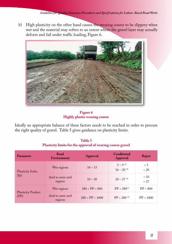
b) High plasticity on the other hand causes the wearing course to be slippery when wet and the material may soften to an extent where the gravel layer may actually deform and fail under traffic loading, Figure 6.
Figure 6Highly plastic wearing course
Ideally an appropriate balance of these factors needs to be reached in order to procure the right quality of gravel. Table 5 gives guidance on plasticity limits.
Table 5Plasticity limits for the approval of wearing course gravel
Parameter Road Environment Approval Conditional
Approval Reject
Plasticity Index (Ip)
Wet regions 10 – 155 – 9 (1)
16 – 20 (2)
< 5> 20
Arid to semi-arid regions 10 – 20 20 – 27 (3) < 10
> 27
Plasticity Product (PP)
Wet regions 280 < PP < 800 PP < 280(1) PP > 800
Arid to semi-arid regions 280 < PP < 1000 PP < 280 (1) PP > 1000

12
Increased Application of Labour-Based Methods Through Appropriate Engineering Standards
Conditional approval:
1) Material can be used on condition that it is fine-graded (percentage passing 75µm sieve > 20% and percentage passing 5 mm > 50% and nominal size < 10mm. GM< 1.9 and traffic < 50vpd
2) The plasticity range is on the high side and the gravel can be approved for use if the traffic is low (< 20 vpd) or if the material has low fines (percentage passing 75µm sieve < 30%) and the road is in semi-arid to arid regions.
3) Material can be approved if it is well-graded with < 20 mm nominal maximum aggregate size. The plastic material acts as a bonding matrix within the gravel layer.
2.3 California Bearing Ratio (CBR)
Determination of the CBR of wearing course gravel is optional because if gravel satisfies the grading and plasticity specifications then it will most likely meet the CBR specifications. However, in the case where the material is highly marginal in the sense that it is conditionally approved on most of the parameters then its bearing capacity cannot be assured. If the wearing course is to be used on a road where the traffic is of relatively high volume (> 50 vpd where a significant proportion (> 50% are heavy vehicles) then CBR tests should be considered necessary.
The CBR tests should be carried out at 95% of maximum dry density obtained through Modified AASTHO or BS Heavy (4.5 kg hammer) compaction test with 4 days soaking. The approval guidance on the minimum CBR of the wearing course is given in Table 6.
Table 6 Approval guidance on minimum CBR of wearing course
Soaked CBR Values of Wearing Course Gravel
Parameter Road structure Approval Conditional Approval Reject
CBR (%)Wet regions 20 15 (1) < 15
Arid to semi-arid regions 15 10 (2) < 10

13
Guideline for Quality Assurance Procedures and Specif ications for Labour-Based Road Works
Conditional Approval:
1) Material may be approved on condition that there are no sources with better material within economical haulage distances (also having considered the use of trucks instead of tractor-trailer combination), or that the traffic is low, or the road is classified as an access road.
2) Material may be used if the traffic is low and better material cannot be sourced within economical haulage distances, and if the road environment is not prone to prolonged flooding.
3. Materials for Concrete WorksThis section deals with approval of aggregate for use in concrete mixes, incorporating both fine and coarse aggregate. Fine aggregate includes pit-sand, river-sand and any other similar fine aggregate that could be used in concrete mixes. Coarse aggregate, sometimes referred to as concrete stone, can be crushed stone from established quarries, hand-crushed stone or naturally occurring aggregate. For labour-based works, the use of natural aggregate or hand-crushed stone is viewed in the context of using locally available resources and is greatly encouraged. However, shortcomings arise if conventional specifications are used for approval purposes. Natural aggregate tends to be weak if exposed to weathering and rounded if extracted from river gravel. Hand-crushed stone tends to be larger and flakier. In such cases if conventional specifications are used for approval then the likelihood of the aggregate being rejected is very high, despite the fact that natural or hand-crushed stone aggregate has been used successfully many times.
Below are parameters and criteria that can be used to approve aggregate earmarked for use in concrete mixes on labour-based projects. In some cases the criteria differ from the conventional.
3.1 Coarse Aggregate
The particle size distribution is an important factor in the approval process because it is has a bearing on the overall strength of the concrete.
3.1.1 Crushed Stone Aggregate
Crushed stone aggregate from established quarries is usually produced from competent rock and crushed with tailor-made mechanical jaws, Figure 7. The crushed stone is graded using mechanical sieves and the quality is generally good. However, samples should be collected and tested for gradation (see Table 7). Enough samples (approx. 0.1 m3) should be collected in order to carry out trial mixes for the concrete mix design.
14
Increased Application of Labour-Based Methods Through Appropriate Engineering Standards
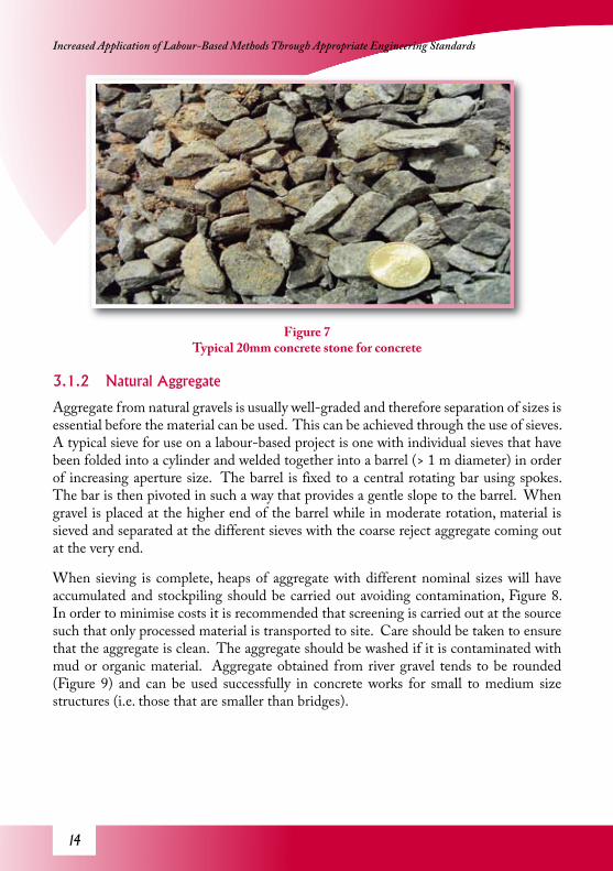
Figure 7Typical 20mm concrete stone for concrete
3.1.2 Natural Aggregate
Aggregate from natural gravels is usually well-graded and therefore separation of sizes is essential before the material can be used. This can be achieved through the use of sieves. A typical sieve for use on a labour-based project is one with individual sieves that have been folded into a cylinder and welded together into a barrel (> 1 m diameter) in order of increasing aperture size. The barrel is fixed to a central rotating bar using spokes. The bar is then pivoted in such a way that provides a gentle slope to the barrel. When gravel is placed at the higher end of the barrel while in moderate rotation, material is sieved and separated at the different sieves with the coarse reject aggregate coming out at the very end.
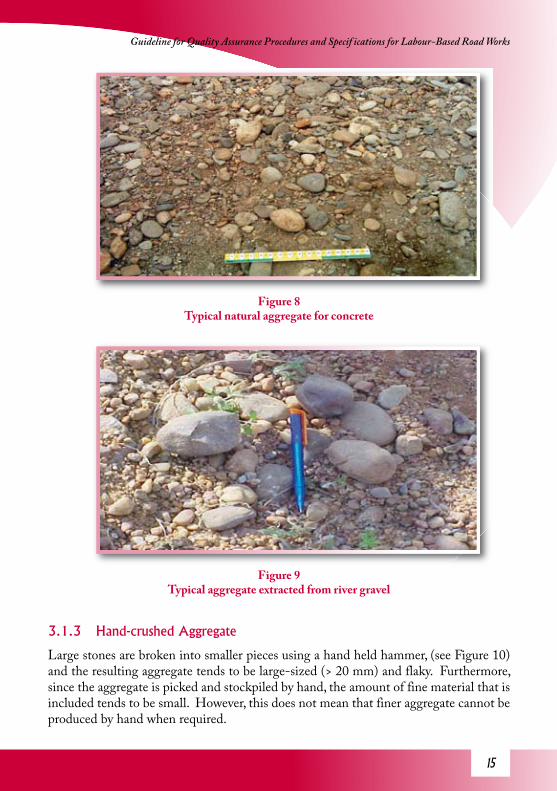
When sieving is complete, heaps of aggregate with different nominal sizes will have accumulated and stockpiling should be carried out avoiding contamination, Figure 8. In order to minimise costs it is recommended that screening is carried out at the source such that only processed material is transported to site. Care should be taken to ensure that the aggregate is clean. The aggregate should be washed if it is contaminated with mud or organic material. Aggregate obtained from river gravel tends to be rounded (Figure 9) and can be used successfully in concrete works for small to medium size structures (i.e. those that are smaller than bridges).
1�
Guideline for Quality Assurance Procedures and Specif ications for Labour-Based Road Works
Figure 8Typical natural aggregate for concrete
Figure 9Typical aggregate extracted from river gravel
3.1.3 Hand-crushed Aggregate
Large stones are broken into smaller pieces using a hand held hammer, (see Figure 10) and the resulting aggregate tends to be large-sized (> 20 mm) and flaky. Furthermore, since the aggregate is picked and stockpiled by hand, the amount of fine material that is included tends to be small. However, this does not mean that finer aggregate cannot be produced by hand when required.

1�
Increased Application of Labour-Based Methods Through Appropriate Engineering Standards
Figure 10Hand crushing activity (site)
3.1.4 Grading Parameters
The following grading envelopes provide a guide for the approval of coarse aggregate for concrete (concrete stone).
Table 7Grading envelopes for concrete aggregate for hand crushed stone
Sieve Size (mm)
Grading envelopes
40 mm -concrete stone 20 mm concrete stone 10 mm concrete stone
50 100
37.5 85 – 100
26.5 0 – 60 100
20 0 – 25 85 – 100
13 0 – 10 50 – 85 100
9.5 25 – 55 80 – 100
6.7 10 – 30 0 – 60
4.75 0 – 15 0 – 10
Figure 10Figure 10

1�
Guideline for Quality Assurance Procedures and Specif ications for Labour-Based Road Works
Aggregate that does not meet the above grading criteria should not be rejected immediately. Trial concrete mixes should be carried out in order to determine the resultant concrete strength. The aggregate should be approved on the condition that the cube or cylinder strengths meet the 28-day strength specifications.
If the gradation of the aggregate falls within the envelopes given above then a grading approval should be given.
3.1.5 Flakiness
Flakiness, a measure of how thin or flat the individual aggregate particles are, is usually a problem associated with hand crushed stone and certain rock types such as blue limestone. However, the structures associated with labour-based works are low-cost structures, and flakiness should not normally be used as an approval parameter. Flakiness should only be considered if the aggregate is intended for the construction of structures larger than a small size box culvert (< 1.5 m span).
3.1.6 Aggregate Strength
The strength of the aggregate is of paramount importance. Aggregate particle interlock contributes immensely to the overall compressive strength of concrete. Weak aggregate is undesirable in concrete and should be rejected. The strength of the aggregate can be determined using the aggregate crushing value test or the ten percent aggregate crushing value test.
• The Aggregate Crushing Value should not exceed 30.
or
• The Ten Percent Aggregate Crushing Value should not exceed 12 tonne or 100 kN for concrete that is exposed to abrasion, or 8 tonne for other situations.
In the case where capacity to test is not available, simpler indicator tests may be carried out. At least 200 representative aggregate particles should be selected from a representative sample and placed on a hard surface. Each stone is then hammered once with an ordinary claw hammer. If more than 10% of the stones crumble to fine particles or pulverise then the aggregate should be rejected. This method is only applicable to aggregate earmarked for the construction of small structures.

1�
Increased Application of Labour-Based Methods Through Appropriate Engineering Standards
3.2 Fine AggregateFine aggregate that is used in concrete includes river-sand, quarry-sand and other similar fine aggregate, Figure 11. While contributing to the strength of concrete, the fine fraction also acts as filler occupying the spaces between the coarse aggregate. Sand, the most abundantly occurring natural fine aggregate, is available in two main forms namely river-sand and pit-sand. River-sand is the most appropriate for use in concrete because it generally meets the grading requirements and it is also usually clean having been washed by water currents. Pit-sand is usually highly contaminated because it is usually deposited by run-off which tends to contain a lot of organic materials. Care should be taken when using pit-sand instead of river-sand for concrete works. However, pit-sand can be blended with river-sand in situations where the river-sand is too coarse.
Gradation and level of contamination are the main parameters that are used for the approval of fine aggregate for use in concrete.
Figure 11Typical river sand sample
3.2.1 Grading
Table 8 gives guidance on the grading envelope for fine aggregate regardless of source (natural deposits or established quarries).

1�
Guideline for Quality Assurance Procedures and Specif ications for Labour-Based Road Works
Table 8 Grading envelope for fine aggregate for use in concrete
Sieve Size (mm) Percentage Passing
6.7 100
4.75 95 – 100
2.36 70 – 100
1.18 45 – 100
0.6 20 – 75
0.3 7 – 35
0.15 2 – 15
0.075 0 – 5
Fine aggregate with gradation that falls within this envelope should be given gradation approval. Fine aggregate with gradation that falls outside the envelope should not be automatically rejected but should be used in a trial mix design and if the overall concrete strength specifications are met, then the aggregate should be conditionally approved.
3.2.2 Contamination Levels
High contamination levels in aggregate can cause significant reduction in concrete strength and should therefore be checked in the approval process. In order to avoid complications that are brought about by more sophisticated methods a simplified method should be used for purposes of approval.
The aggregate should be placed in a transparent container e.g. a bottle with a small diameter and straight vertical walls. A measuring cylinder is appropriate for this purpose. The container should be half-filled with a representative sample of the aggregate and water should be poured into the container until it is ¾ full. The contents should be shaken for at least 5 minutes before the container is placed on a flat surface and allowed to stand for at least 3 hours.
Sedimentation occurs in a graded fashion with the coarser material at the bottom and the finer material at the top. If there is evidence of clay within the aggregate or if the water above the sediment remains turbid (dirty) after 3 hours, then sedimentation should be allowed to continue for at least 12 hours. When sedimentation is complete the thickness of the top layers with undesirable material should be measured without

20
Increased Application of Labour-Based Methods Through Appropriate Engineering Standards
disturbing the container. The measured thickness of the undesirable material ( t ) should be expressed as a percentage of the total thickness of the sediment (T ).
Contamination level
The contamination level should not be greater than 5% in order for aggregate to be approved. Aggregate with a contamination level more than 5% may be approved on condition that, when used in a trial concrete mix, the resultant strength of the concrete meets specifications. Otherwise the aggregate should be rejected.
3.3 Water SourcesWater is an important ingredient in concrete works. Concrete hardens and gains strength through a chemical reaction which requires water of hydration. However, a high content of impurities in the water affects or inhibits the hydration process resulting in weaker concrete. For this reason water sources should be approved before use. In general, there is really no need to test the water as long as it appears clean.
All drinkable water should be approved for use in concreting without carrying out verification tests on it.
Water that looks dirty (high turbidity) or hard, such as that often obtained from ground sources or wells, should be assessed. If the intended concrete structure is no larger than a small box culvert then an assessment through a trial concrete mix will suffice.
The water source should be approved on condition that the concrete strength specifications are met.
For larger structures trialling alone is not sufficient. The water should be sampled into clean containers and tested for both organic and inorganic contents. 500 ml of water should be placed in a pre-weighed steel or platinum dish and the water evaporated on a water bath. Once dry, the dish should be heated at 132oC for 1 hour, then cooled and weighed.
The total solids in water = 100 x (mass of residue in grams/mass of water)

21
Guideline for Quality Assurance Procedures and Specif ications for Labour-Based Road Works
3.4 Concrete Mix Designs
3.4.1 Common Mix Designs
Concrete structures are by their nature very expensive. As a matter of principle, concrete mix designs should be carried out on each and every project in order to avoid under-design or over-design of the concrete structures. An under-designed structure is one that is weaker than desirable and is more likely to fail. The remedy may include replacement, which may increase the costs by more than two fold. Over-designed structures are too strong because they are built with very rich concrete. This results in wastage of materials by unnecessarily consuming more material and associated financial resources.
In order to simplify specifications, concrete is divided into different classes, Table 9. The numeric following the letter ‘C’ is the nominal compressive strength expressed in MN/m2.
Table 9 Classes of concrete
Type Class Intended Structures Remarks
Lean Concrete
Class P / C10 Blinding
Blinding is concrete that is used to level out foundations prior to construction of the main structure. Strength is not of great importance.
Mass Concrete
Class Q / C15
Gravity structures e.g. gravity retaining walls
These are structures that serve their purposes through their weight rather that compressive strength.
Structural Concrete
C20Culvert slab and surround, concrete members wholly in compression, footings of small bridges
C20 concrete can be used in both reinforced and plain concrete which is generally in compression and stresses are evenly distributed.
C25
Pre-cast concrete ring culvert pipes, box culvert decks, piers and abutments, and footings of small bridges
Suitable for structures with concentrated stress such as those produced by bending moments in the members.
C30Decks and beams of medium size bridges, and piers and abutments of major bridges
These are structure designed to withstand high stresses and adverse conditions such as attrition forces attributed to storm flow or flooding.
C40 Decks and beams of major bridges Such structures tend to have long spans i.e. in excess of 15 m

22
Increased Application of Labour-Based Methods Through Appropriate Engineering Standards
The strength of concrete depends on the proportions of cement, fine and course aggregate and water. Table 10 gives a guide on mix proportions that could be used to produce various classes of concrete.
Table 10 General concrete mix proportions for given classes of concrete
Concrete type Class of concrete Approximate mix proportions by volume
Maximum aggregate size
Lean Concrete Class P / C10 1:4:8 40 mm
Mass Concrete Class Q / C15 1:3:6 50 mm
Structural ConcreteC20 1:2:4 20 mm
C25 1:1.5:3 25 mm
It should be noted that the mix proportions given in Table 10 do not necessarily produce the corresponding concrete class because there are other factors that affect the strength of concrete. These factors include aggregate type, quality, strength, gradation, contamination levels of the aggregate and water, and others such as cement/water ratio, quality of cement, compaction etc.
However, the approximate concrete mix proportions do provide a starting point for trial mixing which will eventually result in mix designs for approval. The strength of concrete is very much dependent on the aggregate/cement ratio and water/cement ratio. Therefore trial mixes are carried out using varying proportions of the ingredients. Table 11 gives guidance on expected combined grading of the fine and coarse aggregate, specified in the form of grading envelopes.
23
Guideline for Quality Assurance Procedures and Specif ications for Labour-Based Road Works
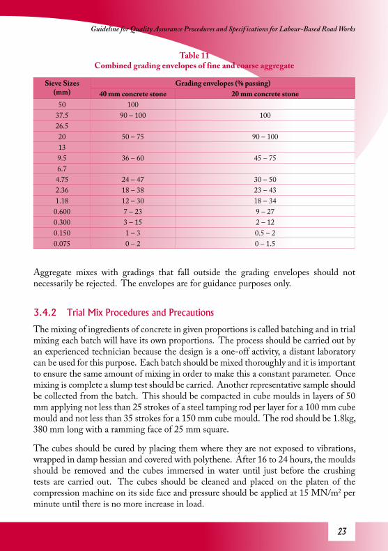
Table 11 Combined grading envelopes of fine and coarse aggregate
Sieve Sizes (mm)
Grading envelopes (% passing)40 mm concrete stone 20 mm concrete stone
50 10037.5 90 – 100 10026.520 50 – 75 90 – 100139.5 36 – 60 45 – 756.74.75 24 – 47 30 – 502.36 18 – 38 23 – 431.18 12 – 30 18 – 340.600 7 – 23 9 – 270.300 3 – 15 2 – 120.150 1 – 3 0.5 – 20.075 0 – 2 0 – 1.5
Aggregate mixes with gradings that fall outside the grading envelopes should not necessarily be rejected. The envelopes are for guidance purposes only.
3.4.2 Trial Mix Procedures and Precautions
The mixing of ingredients of concrete in given proportions is called batching and in trial mixing each batch will have its own proportions. The process should be carried out by an experienced technician because the design is a one-off activity, a distant laboratory can be used for this purpose. Each batch should be mixed thoroughly and it is important to ensure the same amount of mixing in order to make this a constant parameter. Once mixing is complete a slump test should be carried. Another representative sample should be collected from the batch. This should be compacted in cube moulds in layers of 50 mm applying not less than 25 strokes of a steel tamping rod per layer for a 100 mm cube mould and not less than 35 strokes for a 150 mm cube mould. The rod should be 1.8kg, 380 mm long with a ramming face of 25 mm square.
The cubes should be cured by placing them where they are not exposed to vibrations, wrapped in damp hessian and covered with polythene. After 16 to 24 hours, the moulds should be removed and the cubes immersed in water until just before the crushing tests are carried out. The cubes should be cleaned and placed on the platen of the compression machine on its side face and pressure should be applied at 15 MN/m2 per minute until there is no more increase in load.

24
Increased Application of Labour-Based Methods Through Appropriate Engineering Standards
The compressive strength of the concrete is expressed as the maximum load recorded on the machine to the nearest 0.5 MN/m2 (0.5 MPa).
It should be noted at this stage that approvals are given on the basis of over-design levels. This principle takes into account the difficulties of replicating conditions stipulated in the procedure on structural members cast in-situ. The approvals are carried out according to over-designs given in Table 12.
Table 12 Over-design to meet strength requirements
Number of tests
Standard deviation (MPa)2.0 3.0 4.0 5.0
15 3.1 4.7 7.3 10.020 2.9 4.3 6.6 9.1
30+ 2.7 4.0 5.8 8.2
The required over-design value obtained from Table 12 is the value corresponding to the number of strength tests carried out (given in the left hand column) and the standard deviation of the strength test results (given in the top row). The mix design should be approved if the average strength of the trial mix (Sd) is greater than or equal to the specified concrete strength of the structural member (C) plus the over-design value (So)
od SCS += (1)
The mix design is the mix proportions of cement, coarse and fine aggregate, and water that satisfy the equation above.
For example:
If 15 tests are carried out and the analysis of the cube strengths gives a standard deviation of 5.0 then approval should be given if the average strength of the trial mix is greater than or equal to the specified concrete strength of structural member plus 10 MPa. For a specified strength of 20 MPa the strength for the trial mix should be ≥ 30 MPa.

2�
Guideline for Quality Assurance Procedures and Specif ications for Labour-Based Road Works
Part B – Approval of Construction Works
This section covers works quality assurance and approval specifications for labour-based work activities.
4. Approval of Works ActivitiesConstruction works include all activities that relate to the actual building of the road. The major activities are given in Table 13.
Table 13 Labour-based construction activities
Activity Description
1 Setting outSetting horizontal and vertical alignments, quan-tities of excavation and fill to achieve the required final road levels, position drainage structures, etc
2 Bush clearing Removal of shrubs and trees3 Stripping and grubbing Removal of grass cover, debris, humus etc
5 Road-bed preparation Excavation to level; providing a level cross-section on which the road can be formed
6 Formation Excavation of drains and forming the camber
7 Subgrade compaction Watering and rolling of subgrade to specified levels of compaction
8 Drainage structures Excavation for drainage structures and construc-tion of the structures
9 Gravel extraction Gravel excavation and stockpiling
10 Loading, off-loading and spreading gravel
Techniques used to improve loading and off-load-ing efficiency. Spreading to achieve the required thickness
11 Gravel compaction
Watering and rolling to achieve specified den-sification, skimming to provide a smooth riding surface and quality control measures through field test or method specification
12 Cladding Use for top-soil on the edges to confine the gravel and encourage vegetative growth
14 Erosion protection works Construction features and structures that prevent or minimise erosion damage
2�
Increased Application of Labour-Based Methods Through Appropriate Engineering Standards
15 Final Clearing Clearing site of undesirable items such as debris; rocks, wood, excess soil, etc
16 Inspection for project completion
Carrying out inspections for completion of works for the issuance of project completion certificate
17 Inspection for end of defects liability period
Carrying out inspections at the end of the main-tenance period for the issuance of the end of the defects liability period
In order to accept a completed section of the works, it is essential to carry out some basic quality control measures on selected activities. This becomes very important if the work is carried out by private contractors where the requirement to ensure that the client gets value for money is paramount. The verification of quality would also require that tests are carried out on completed works both in the field and the laboratory.
This Guideline is also aimed at providing simplified methods and tests for approvals without compromising the quality of work or products. This takes into account the fact that some of the projects are carried out in very remote areas and the project scope may be low such that setting up a fully flanged laboratory may be uneconomical. Distances to the nearest established laboratories may also be too long making it impractical for frequent visits to test samples. In the case where this alternative is used, it would take a long time for results to be made available thereby seriously delaying approvals. Delaying of approvals should be avoided at all times and by all means because it impacts negatively on the contractors’ cash-flow and the project as a whole.
4.1 Setting OutSetting out (Figure 12) is usually a difficult activity to approve. Labour-based works are usually carried out on low-volume roads of which geometrical specifications are not as stringent as on conventional projects. The principle is to try as much as possible to follow the existing road or ground profiles in order to avoid deep cuts and high fills, thus minimising the earthworks. However, limits for the approvals should be set on the basis of 60 km/h design speed whilst accommodating the influence of difficult terrain on geometry. Table 14 gives guidance on the approval limits.
Key parameters that should be checked include:• Carriageway width
• Width of road reserve
• Longitudinal gradient
• Cross-sectional profiles

2�
Guideline for Quality Assurance Procedures and Specif ications for Labour-Based Road Works
Figure 12Setting out activity
Table 14Approval limits for setting out
Item Approval Conditional Approval Reject
Task rates As in specificationsNot exceeding
specifications by more than 10% (1)
Exceeding specifications by
10%
Gradient ≤ 12% 13 – 17% (2) > 17%
Radius of Curvature ≥ 100 m≥ 50 m (3)
≥ 5 m (4) < 5 m
Stopping sight distance ≥ 80 m ≥ 40 m (5) < 40 m
Carriageway Width ≥ 6m 4.5m ≤ width < 6m(6) <4.5m
Conditional Approval:
1) Labour-based tasks are internationally accepted because labour daily outputs have been developed to be fair and non-exploitative and also endorsed by ILO/ASIST. However, despite the existence of international labour standards, there is tendency by contractors to over-task and maximise profit. It is therefore important to empower the supervising engineers to prevent over-tasking from occurring on site. A maximum of 10% error is therefore permissible on condition
2�
Increased Application of Labour-Based Methods Through Appropriate Engineering Standards
that it is not systematic. Systematic over-tasking refers to a situation where more than 25% of labourers are over-tasked.
2) A gradient of 13 – 17% may be acceptable on condition that there is no better alternative route and the length of the steep section is not more than 100m. If the length of the steep section is longer than 100m then it would be unsafe for laden heavy vehicles both during climbing and braking while descending. Gradients steeper than 17% are too steep and could pose serious danger to all traffic especially when the ground is wet.
3) Radius of curvature is a very important element in horizontal profile design. However, difficult terrain may require that tighter curves are designed. A minimum radius of 50m is acceptable on condition that the terrain is difficult or hilly.
4) Radii between 5m and 50m may be approved if the terrain is very difficult such as in mountainous areas where wider curves are not possible, or where obstruction and property boundaries need to be avoided.
5) A stopping sight distance between 40 – 79 m may be approved on condition that the terrain is difficult and there is no alternative. In the case where stopping sight distance is shorter than 40m the road should be made wide enough for two heavy vehicles to pass while keeping as close as possible to the verge side of the road (approx. ≥6m carriageway) coupled with appropriate lower speed limits and adequate warning signs.
6) Road width hinges on safety in terms of there being a possibility of two large vehicles passing each other safely at the design speed for relatively high traffic volumes (>50vpd.) or at a low speed for very low traffic volumes where such vehicular conflict is minimal. Road width ≥ 4.5m and < 6m is acceptable on condition that the road is expected to be carry < 50 vpd., and there is no possibility for upgrading during its design life (typically 20 years). Where there is the possibility of high traffic mix (vehicles, carts, bicycles, pedestrians, etc.) the minimum width should be 6m.

2�
Guideline for Quality Assurance Procedures and Specif ications for Labour-Based Road Works
Figure 13Bush clearing and roadbed preparation
4.2 Bush ClearingBush clearing involves the removal of trees and stumps, and bushes (Figure 13). Approval of bush clearing is straightforward. Bushes within the right of way should be cleared and the stumps removed. The roots should be removed to a depth of more than 200 mm below ground level. However, certain protected trees may be marked for exemption and the approval should take cognisance of these overriding instructions.
4.3 Stripping and Grubbing
Figure 14Stripping and grabbing activity completed
30
Increased Application of Labour-Based Methods Through Appropriate Engineering Standards
Stripping and grubbing is an activity (Figure 14) that involves the removal of grass and small bushes. The activity should be carried out only within the confines of the right of way unless instructed otherwise. However, the approval should consider that stripping and grubbing does not include the complete removal of grass roots because this would involve excavation-to-waste to a depth of 200mm.
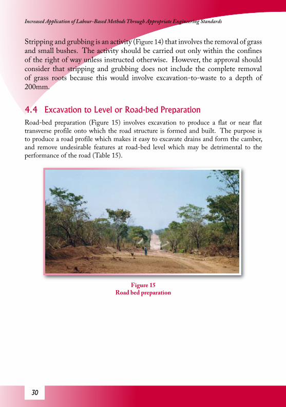
4.4 Excavation to Level or Road-bed PreparationRoad-bed preparation (Figure 15) involves excavation to produce a flat or near flat transverse profile onto which the road structure is formed and built. The purpose is to produce a road profile which makes it easy to excavate drains and form the camber, and remove undesirable features at road-bed level which may be detrimental to the performance of the road (Table 15).
Figure 15Road bed preparation

31
Guideline for Quality Assurance Procedures and Specif ications for Labour-Based Road Works
Table 15 Parameters for the approval of road-bed preparation
Item Approval Conditional Approval Reject
Ant-hills
All anthills removed to full-depth and treated
All anthills excavated to 300 mm below road-bed and backfilled without treatment.(1)
Anthills not excavated and treated
Stone and rock outcrops
Stones > 50mm removed from right-of-way and no visible rock outcrops at road-bed level
•Maximum stone or rock outcrop above road-bed ≤ 50 mm (2)
•Maximum stone or rock outcrop above road-bed ≤ 100 mm (3)
•Maximum rock outcrop > 50 mm
•Maximum rock outcrop > 100 mm
Roots
•No roots protruding above the road-bed level•No roots > 50 mm thick visible at road-bed level
-
•Roots protruding above road-bed level•Roots > 50 mm thick are visible at road-bed level
Fill Compaction
Compaction carried out with ≥ 6 passes of a 1 - 1.7 ton vibratory roller or equivalent effort on layers ≤ 150 mm thick
Compaction carried out with ≥ 6 passes of a 1 - 1.7 ton vibratory roller or equivalent effort for layer thickness between 150 – 175 mm (4)
< 6 passes of 1 - 1.7 ton vibratory roller, or layer thickness > 175 mm
If material is too coarse or too plastic, appropriate rollers and compactive effort should be used.
Conditional Approval:
1) Anthills are a serious problem in that in the majority of cases they grow out of the road creating unbecoming features on the carriageway, shoulders or drains. The worst case scenario occurs when the anthill collapses resulting in large holes on the road. Approval may be given on condition that the road is low trafficked (< 20vpd).
2) The section may be approved on condition that rock outcrops are isolated and would not have an effect on the compaction activity and the general performance of the road.
3) Approval may be given on condition that the road is a minor feeder or access

32
Increased Application of Labour-Based Methods Through Appropriate Engineering Standards
road and the rock is large and widespread such that the excavation would be very costly, and wearing course can be successfully placed on top of the rock bed.
4) The compaction of fill may be approved on condition that the material is easily compactable, well graded, and with good compaction moisture. Otherwise the number of passes should be increased or a larger roller should be used.
4.5 FormationThe formation activity (Figure 16) involves the excavation of drains; the material cut from the drains is then placed on top of the road-bed to form the subgrade layer and shaped to form the required camber. It is important to get the camber right at this stage. Also, drain excavation should be perfected at this stage to prevent profiles that may encourage ponding or result in water flowing in undesired directions. The material that is excavated from the side-drains must be of subgrade quality (see Section 1). Reject material such as large stones should be removed during drain excavation, spreading and shaping of the subgrade material. The subgrade should be formed to a camber of 8 % or as specified or instructed by the supervising engineer. The specifications for approvals are given in Table 16.
Figure 16Formation activity

33
Guideline for Quality Assurance Procedures and Specif ications for Labour-Based Road Works
Table 16 Approval specifications for the formation
Item Approval Conditional Approval Reject
Cross-sectional profile Profile board fitting well
Profile board fitting on ≥ 70% of tests (1)
Profile board fitting on < 70% of tests
Camber(8% recommended)
As specified ± 1% As specified ± 2% and actual camber ≥ 4% and < 10% (2)
Camber > 10%,Camber < 4%
Invert levels of drains
• Direction of water flow corresponding to location of water discharge structures
• Longitudinal profile not susceptible to ponding
-
Storm-water will not flow in the desired direction or ponding likely to occur
Thickness of Compacted Subgrade
New constructiontavg ≥ tspec – 25mm ≤ tspec + 25mmtmin = tspec – 35mm
Upgrading Existing Earth Roadtavg < tspec – 25mmtmin < 25mm (3)
New constructiontavg < tspec – 25mm tmin < tspec – 35mm
Note:
tspec required thickness as specified in the project documents. For labour-based works 150 mm subgrade thickness is usually specified
tavg average thickness measured on a completed section at 6 positions (minimum); 2 on the right hand side wheel track, 2 on the centreline and 2 on the left hand side wheel track. The section should not be more than 200 m.
tmin minimum thickness measured amongst the six measurements carried out.
Conditional Approval:
1) Approval may be given for works on an access road and in the case where drainage is not impeded and the cross-sectional profile varies slightly from that of the profile board.
2) Approval may be given for a lower camber on condition that the road is situated in a semi-arid to arid region (approx < 700 mm) where rapid dispersal of water from the carriageway is not essential. Higher camber may be approved on condition that the wearing course material is susceptible to rapid deterioration or flattening of the camber.

34
Increased Application of Labour-Based Methods Through Appropriate Engineering Standards
3) Rehabilitation projects sometimes include situations where the existing road structure still has a reasonable profile but with non-existent or inadequate camber (which may require correction). It may also be that the existing carriageway consists of good material, which may be well consolidated and hard. It is therefore important to take advantage of the existing strength of the road structure. In such cases it is not economical to place a 150 mm layer of subgrade and as such approvals may be given for thinner subgrade thickness. However, for new construction the permissible minimum thickness of subgrade should be adhered to and, in this case, approval should be given if the quality of the subgrade meets specifications in Section1 for low-volume trafficked road.
4.6 Subgrade CompactionCompaction is one of the most crucial elements in the approval of labour-based works. There are two aspects to it. Firstly there is the actual compaction, which incorporates the application of appropriate compaction moisture and subsequent rolling aimed at achieving the required field densities. Secondly there is the testing that provides the quantitative verification of the field compaction.
3�
Guideline for Quality Assurance Procedures and Specif ications for Labour-Based Road Works
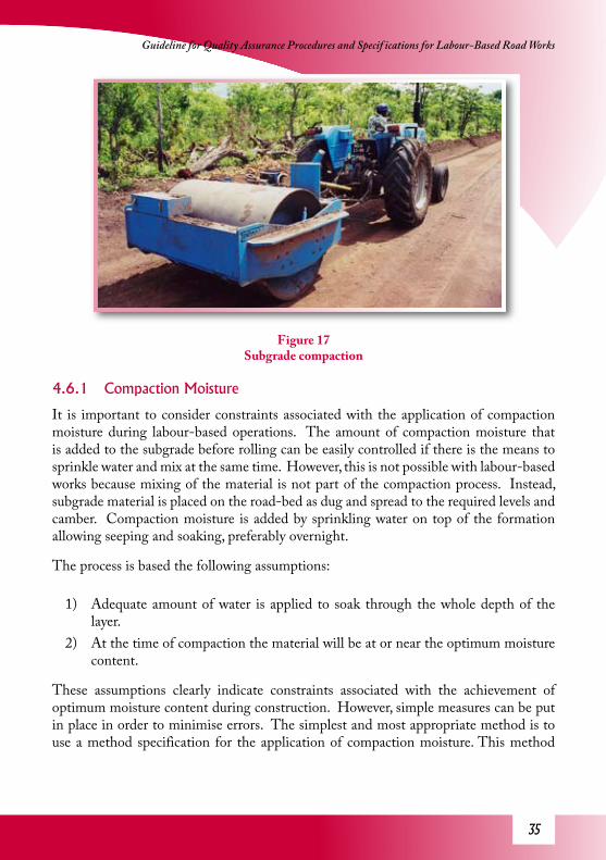
Figure 17Subgrade compaction
4.6.1 Compaction Moisture
It is important to consider constraints associated with the application of compaction moisture during labour-based operations. The amount of compaction moisture that is added to the subgrade before rolling can be easily controlled if there is the means to sprinkle water and mix at the same time. However, this is not possible with labour-based works because mixing of the material is not part of the compaction process. Instead, subgrade material is placed on the road-bed as dug and spread to the required levels and camber. Compaction moisture is added by sprinkling water on top of the formation allowing seeping and soaking, preferably overnight.
The process is based the following assumptions:
1) Adequate amount of water is applied to soak through the whole depth of the layer.
2) At the time of compaction the material will be at or near the optimum moisture content.
These assumptions clearly indicate constraints associated with the achievement of optimum moisture content during construction. However, simple measures can be put in place in order to minimise errors. The simplest and most appropriate method is to use a method specification for the application of compaction moisture. This method
3�
Increased Application of Labour-Based Methods Through Appropriate Engineering Standards
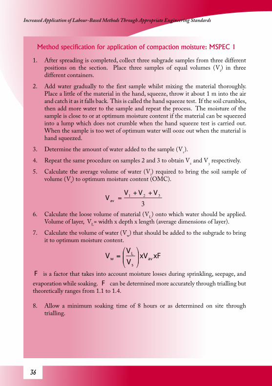
Method specification for application of compaction moisture: MSPEC 1
1. After spreading is completed, collect three subgrade samples from three different positions on the section. Place three samples of equal volumes (Vi) in three different containers.
2. Add water gradually to the first sample whilst mixing the material thoroughly. Place a little of the material in the hand, squeeze, throw it about 1 m into the air and catch it as it falls back. This is called the hand squeeze test. If the soil crumbles, then add more water to the sample and repeat the process. The moisture of the sample is close to or at optimum moisture content if the material can be squeezed into a lump which does not crumble when the hand squeeze test is carried out. When the sample is too wet of optimum water will ooze out when the material is hand squeezed.
3. Determine the amount of water added to the sample (V1).
4. Repeat the same procedure on samples 2 and 3 to obtain V2 and V3 respectively.
5. Calculate the average volume of water (Vi) required to bring the soil sample of volume (Vs) to optimum moisture content (OMC).
6. Calculate the loose volume of material (VL) onto which water should be applied. Volume of layer, VL= width x depth x length (average dimensions of layer).
7. Calculate the volume of water (Vw) that should be added to the subgrade to bring it to optimum moisture content.
F is a factor that takes into account moisture losses during sprinkling, seepage, and evaporation while soaking. F can be determined more accurately through trialling but theoretically ranges from 1.1 to 1.4.
8. Allow a minimum soaking time of 8 hours or as determined on site through trialling.
3321 VVV
V av
++=
xFxVVV
V avs
Lw ⎟⎟
⎠
⎞⎜⎜⎝
⎛=

3�
Guideline for Quality Assurance Procedures and Specif ications for Labour-Based Road Works
specification for the application of compaction moisture, if applied properly, may reduce the need for conventional moisture content testing. However, the moisture content tests still need to be carried out at less frequent intervals for verification purposes. The use of a firewood based sand bath or solar drier would suffice.
4.6.2 Compaction
Once the compaction moisture has been successfully applied, rolling of the section then follows. It is important to note at this stage that different materials have different permeability characteristics. Materials that have low permeability can be problematic in that the sprinkled water may fail to penetrate to the bottom of the layer resulting in two zones, an upper wet zone and dry lower zone. Consequently the upper zone will compact well but the lower zone will remain loose. This will ultimately affect the performance of the road.
Before rolling commences little holes should be dug up in order to determine whether moisture penetrated through the depth of the layer. Once the verification yields positive results then rolling may start. Rolling is aimed at achieving the required field densities. Field densities are an easier method of ensuring that the required CBRs (i.e. the bearing capacities) are achieved. The compactive effort is dependent upon the weight of roller and the mechanical application of compactive force. Subgrade compaction does not require the resultant surface to be smooth, hence for labour-based works tractor-towed pneumatic rollers may be used instead of the traditional pedestrian and small sit-on vibratory smooth-wheeled rollers.
In order to make the management and supervision of subgrade compaction easier a method specification should be employed. The method specification should take cognisance of the fact that different materials behave differently in as far as compactability is concerned. Therefore the compactive effort required to achieve the specified densities is different for each material. However, the approvals of materials detailed in Part A of this Guideline takes into account the limitations associated with compaction equipment commonly used on labour-based projects. On that basis it is possible to employ a method specification for the compaction of subgrade with an acceptable level of confidence.

3�
Increased Application of Labour-Based Methods Through Appropriate Engineering Standards
Method specification to determine the number of passes needed to achieve the required compaction using standard field density tests: M-SPEC 2(i)
1. Prepare a section of subgrade as described previously, taking into account materials specifications in Part A of this Guideline. Also apply compaction moisture in accordance with M-SPEC 1.
2. Collect a representative sample of material from the section and determine the maximum dry density and the optimum moisture content in accordance with standard tests procedures, preferably BS Light (2.5 kg hammer). Alternatively, Modified AASHTO or BS Heavy (4.5 kg hammer) can also be used.
3. Roll the section with the available roller on site. Apply 4 passes of the roller and carry out a sand replacement field density test. Increase the number of passes to 6 by applying two more passes and also carry out a sand replacement field density test.
4. Repeat the process at 8 passes, 10 passes and 12 passes and also repeat the field density test procedure at each stage. Subsequent test points should be in close proximity to the previous test(s) to help maintain consistency.
5. Weigh the material collected from the test holes and dry at 105°C or using the fire heated sand bath method and also weigh the dry material.
6. Calculate the dry density of the material,
7.
dγ = dry density of the material
MW= mass of wet sample from test hole
Vs= volume of sample (same as volume of hole from which the sample was collected)
W= moisture content of the material
8. Express the field dry density as a percentage of the maximum dry density obtained in the laboratory and compare the value with the lower limit specification (Ls) for compaction of the subgrade. Ls = 89% for light compactors using BS Heavy (4.5 kg hammer) and Ls = 95% for light compactors using BS Light (2.5 kg hammer) can be used for this purpose
⎟⎠
⎞⎜⎝
⎛
+⎟⎟⎠
⎞⎜⎜⎝
⎛=
wx
V
M
s
wd
1
1γ

3�
Guideline for Quality Assurance Procedures and Specif ications for Labour-Based Road Works
9. Determine the number of passes, Nmin, at which the specified Ls is achieved by plotting a graph of relative density against the number of passes and read from the graph the value of Nmin corresponding to Ls.
10. Add 2 more passes to the number obtained in 8) and specify the total as the number of passes (Ns) specified for adequate compaction of the subgrade.
There are situations where the scope of the project does not warrant setting up a laboratory on site and the nearest laboratory could be a long distance away. This situation creates serious logistical limitations and may render M-SPEC 2(i) impractical. An alternate method specification (M-SPEC 2(ii)) should be used.
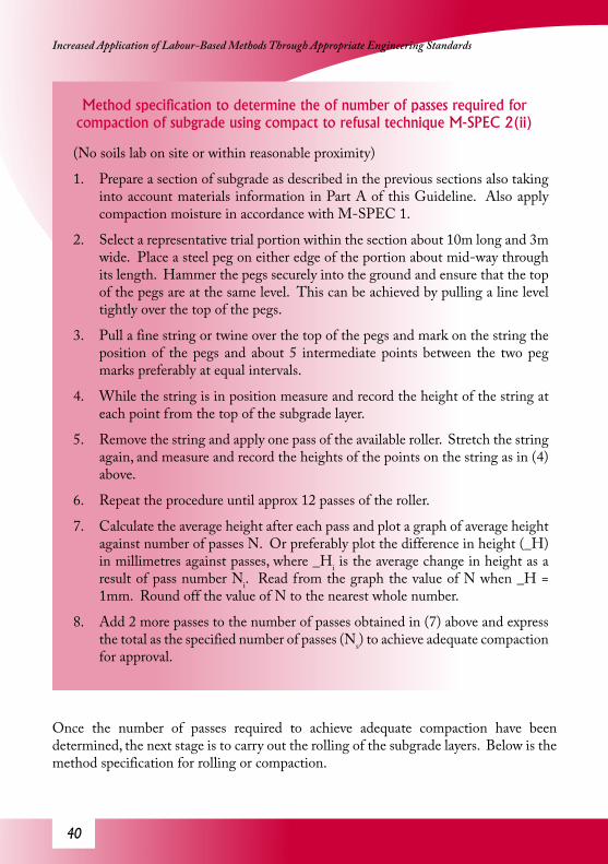
40
Increased Application of Labour-Based Methods Through Appropriate Engineering Standards
Method specification to determine the of number of passes required for compaction of subgrade using compact to refusal technique M-SPEC 2(ii)
(No soils lab on site or within reasonable proximity)
1. Prepare a section of subgrade as described in the previous sections also taking into account materials information in Part A of this Guideline. Also apply compaction moisture in accordance with M-SPEC 1.
2. Select a representative trial portion within the section about 10m long and 3m wide. Place a steel peg on either edge of the portion about mid-way through its length. Hammer the pegs securely into the ground and ensure that the top of the pegs are at the same level. This can be achieved by pulling a line level tightly over the top of the pegs.
3. Pull a fine string or twine over the top of the pegs and mark on the string the position of the pegs and about 5 intermediate points between the two peg marks preferably at equal intervals.
4. While the string is in position measure and record the height of the string at each point from the top of the subgrade layer.
5. Remove the string and apply one pass of the available roller. Stretch the string again, and measure and record the heights of the points on the string as in (4) above.
6. Repeat the procedure until approx 12 passes of the roller.
7. Calculate the average height after each pass and plot a graph of average height against number of passes N. Or preferably plot the difference in height (_H) in millimetres against passes, where _Hi is the average change in height as a result of pass number Ni. Read from the graph the value of N when _H = 1mm. Round off the value of N to the nearest whole number.
8. Add 2 more passes to the number of passes obtained in (7) above and express the total as the specified number of passes (Ns) to achieve adequate compaction for approval.
Once the number of passes required to achieve adequate compaction have been determined, the next stage is to carry out the rolling of the subgrade layers. Below is the method specification for rolling or compaction.

41
Guideline for Quality Assurance Procedures and Specif ications for Labour-Based Road Works
Method specification for compaction of subgrade M-SPEC 3
1. Subgrade shall be laid and compacted in layers conforming to approval specification given in Table 17 and water applied in accordance with M-SPEC 1.
2. The number of passes shall be determined in accordance with M-SPEC 2(i) or M-SPEC 2(ii).
3. Carry out hand squeeze tests on the material in order to ensure that the moisture level is at or near optimum before rolling. The test should be carried out on at least 9 positions in order for the result to be representative of the condition of the section. See M-SPEC 1 item 2 for details.
4. At the same positions of the section, expose the bottom part of the layer in order to ensure that the whole layer is moistened.
5. The most common rollers on labour-based projects are small smooth-wheeled vibratory rollers. It is important to ensure that the roller is in good working order before commencing compaction, especially the vibration.
6. Apply the passes starting from the verge or near-side of the carriageway and progress towards the centreline.
7. Ensure that the overlap when passing back and forth is not less than 100 mm and the roller speed is about 0.9 – 1 km/h.
8. When the first pass is completed, i.e. from the edge to the centre, carry out the second pass also starting from the edge to the centre.
9. Repeat the procedure until the specified number passes has been completed.
Once the method specifications have been followed satisfactorily, subgrade compaction should be approved.
The system however, is not foolproof. The procedures stated in the method specifications are all crucial to obtaining satisfactory compaction and there is a need for checks to be made. In the case where a soils laboratory is available on site or within reasonable distance, random verification checks should be carried out as a measure with which to control workmanship. The random checks should include nationally accepted density testing procedures such as the sand replacement method. However, if the road is classified as an access road the random checks may not be necessary. For higher classes

42
Increased Application of Labour-Based Methods Through Appropriate Engineering Standards
of road the frequency of random checks depends on the functionality of the road, the workmanship required in the contract and professionalism of the supervising consultant and the contractor.
Table 17 Approval specifications for compaction of subgrade
Parameter Approval Conditional Approval Reject
Compaction MoistureMethod specification
No of successful hand squeeze tests
M-SPEC 1 followed and full layer depth wetted
≥ 6/9
M-SPEC 1 followed and ≥ 75% of layer depth wetted (1)
< 6/9 for non-cohesive soil (2)
M-SPEC 1 not followed and/or < 75% of layer depth wetted (*)
< 6/9 for cohesive soils
Number of roller passesMethod specification
M-SPEC 2(i) or M-SPEC 2(ii) followed satisfactorily
M-SPEC 2(i) or M-SPEC 2(ii) not followed satisfactorily
Compaction Method specification
M-SPEC 3 is followed satisfactorily
M-SPEC 3 is not followed satisfactorily
* More water should be applied
Conditional Approval:
1) Approval may be given on material that is not highly sensitive to moisture changes, and this condition is applicable to material meeting specifications given in Section 1.
2) Approval may be given if hand squeeze method cannot be relied upon due to the non-cohesiveness of the material.

43
Guideline for Quality Assurance Procedures and Specif ications for Labour-Based Road Works
5 Wearing Course ApplicationThe wearing course is a crucial component of the design and construction of a gravel road. The important aspects are the layer thickness, compaction moisture and the level of compaction achieved. Other aspects include uniformity of compaction and consistency of gravel type and properties. The consequences of lack of proper consideration of these aspects can be far reaching. For instance, if a gravel layer is not properly compacted the rate of deterioration and rate of gravel loss could be very high, seriously reducing the life of the road.
One of the problems associated with labour-based works is the consistency of gravel. There are cases where gravel is excavated and immediately loaded onto trailers or trucks; the term ‘excavate and load’ is used for this method of operation. Though preferred sometimes, the method causes inconsistencies in the wearing course because each load of gravel may be different. This is usually noticeable if the gravel seam in the pit consists of portions with different colours and grading. After compaction, patches with different colours and grading can be noticeable on the carriageway. This problem makes development of a method specification more difficult as these variations have to be taken into consideration.
5.1 Important AspectsThe procedures for the application and approval of wearing course are more stringent than those of the subgrade. For instance, the required thickness of the wearing course takes into account the need for adequate bearing capacity to carry the traffic and general wear due to traffic and erosion. Uniformity and consistence of the wearing course layer in terms of material properties, layer thickness and compaction are of great importance. It follows therefore that the approval method should endeavour to minimise inadequacies in these aspects.
Consistency of Material Properties: Within the overall constraints associated with the lack of suitable material in acceptable proximity to the project site, there should be no large differences in material properties within the section to be compacted. This can be achieved by excavating and stockpiling the material before haulage. The process of excavation, stockpiling, loading and off-loading, and spreading will help with the mixing of materials to an acceptable extent. ‘Excavate-and-load’ methods usually segregate the gravel, and should be discouraged as consistency cannot be guaranteed.
Layer Thickness: The thickness of the wearing course layer is directly related to the durability of the wearing course itself. The two important aspects to consider are the minimum thickness and the uniformity of the layer. The minimum thickness is meant to ensure adequate strength and uniform deterioration of the gravel layer.

44
Increased Application of Labour-Based Methods Through Appropriate Engineering Standards
Level of Compaction: The wearing course should be well compacted. The in-situ CBR is directly related to the level of compaction achieved. In most cases loosely compacted material wears out quickly under traffic whereas more densely compacted material is more resistant. Uniformity of compaction ensures that there are no weak spots in the section which could develop into potholes or cause localised deformation.
5.2 SpecificationsThe method of excavation and stockpiling of gravel by labour-based methods is described in relevant technical field manuals. Care should always be taken to avoid contamination of the gravel material through mixing with top soil or over-burden and/or underlying layers. There are situations where the gravel seam consists of very coarse material, in which case mixing the gravel with over-burden during excavation and stockpiling results in better quality wearing course. In all cases, the supervising engineer should give approval of the stockpiled material on the basis of the guidelines given in Part A of this Guideline. In order to mix overburden and the gravel the implementing agent should carry out regular gradation tests (sieve analysis) and plasticity tests to ensure that the stockpiled material after mixing is within specifications.
When the gravel material is placed on the road, spreading and levelling follows. Care should be taken to ensure that segregation does not occur.
Table 18 Approval specifications for placement of wearing course
Parameter Approval Conditional Approval Reject
Cross-sectional profileProfile board compliance check
Profile board fitting properly
Profile board fitting on ≥ 75% of the tests (1)
Profile board fitting on < 75% of tests
CamberRecommended: 8%
As specified ± 1% Specified ± 2% and actual camber ≥ 4% and < 10% (2)
Camber > 10%,Camber < 4%
Drain levels As per the design Not as per design but discharging in the desired direction (3)
Not as per design and not discharging in desired direction
Wearing course thickness
New constructiontavg ≤ tspec + 25 mm,tavg ≥ tspec – 15 mm,tmin ≥ tspec – 20 mm
New constructiontavg > tspec + 25mm (4)
New Constructiontavg > tspec + 25 mmtavg < tspec – 15 mmtmin < tspec – 20 mm

4�
Guideline for Quality Assurance Procedures and Specif ications for Labour-Based Road Works
Note:
tspec required thickness as specified in the project documents (for most gravel roads 150 mm is usually specified).
tavg average of thickness measured on a completed section at 6 positions; 2 on the right hand side wheel track, 2 on the centreline and 2 on the left hand side wheel track. The section should not be more than 200 m long.
tmin minimum thickness measured amongst the six measurements carried out.
Conditional Approval:1) The section may be approved on condition that the road is low trafficked (< 20
vpd) and that drainage is not compromised as a result.
2) The section may be approved on condition that the road is situated in an arid region where the need to discharge water from the carriageway is not critical or in the case where the material is clayey such that wear of the gravel layer is limited or where the traffic volume is low (< 20 vpd).
3) Approval may be given on condition that the road is situated in a low rainfall area (< 700 mm) or side-drains have adequate discharge capacity to prevent run-off from filling up to wearing course level and effects are taken care of through remedial measures.
4) Approval should be given if the riding quality is acceptable to the engineer and the contractor does not claim for the extra material. The layer thickness should also be within the specification limits.
The approval specif ication for layer thickness: implies that the contractor should have the means to determine accurately the thickness of loose uncompacted gravel. It is important at this stage to give a simple method to determine the bulking factor of the gravel material. The bulking factor is a numerical multiplier relating the uncompacted volume to the compacted volume of the gravel. Assuming the width of the layer is uniform, the thickness of the layer is directly proportional to the volume of the layer. Hence the bulking factor for the material is equal to the multiplier for layer thickness. For most gravel material a bulking factor of 1.2 is applicable. This implies that in order to get a compacted thickness of 150 mm the uncompacted layer thickness should be 180 mm (= 150 mm x 1.2). Whenever the bulking factor needs to be determined, a trial should be carried out (see Section 5.3).
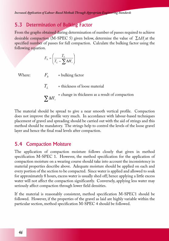
4�
Increased Application of Labour-Based Methods Through Appropriate Engineering Standards
5.3 Determination of Bulking FactorFrom the graphs obtained during determination of number of passes required to achieve desirable compaction (M-SPEC 5) given below, determine the value of ∑∆Hí at the specified number of passes for full compaction. Calculate the bulking factor using the following equation.
Where: bF = bulking factor
LT = thickness of loose material
= change in thickness as a result of compaction
The material should be spread to give a near smooth vertical profile. Compaction does not improve the profile very much. In accordance with labour-based techniques placement of gravel and spreading should be carried out with the aid of strings and this method should be mandatory. The strings help to control the levels of the loose gravel layer and hence the final road levels after compaction.
5.4 Compaction MoistureThe application of compaction moisture follows closely that given in method specification M-SPEC 1. However, the method specification for the application of compaction moisture on a wearing course should take into account the inconsistency in material properties describe above. Adequate moisture should be applied on each and every portion of the section to be compacted. Since water is applied and allowed to soak for approximately 8 hours, excess water is usually shed off; hence applying a little excess water will not affect the compaction significantly. Conversely, applying less water may seriously affect compaction through lower field densities.
If the material is reasonably consistent, method specification M-SPEC1 should be followed. However, if the properties of the gravel as laid are highly variable within the particular section, method specification M-SPEC 4 should be followed.
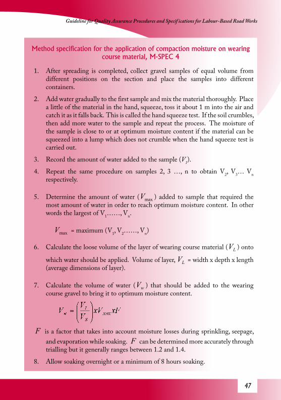
4�
Guideline for Quality Assurance Procedures and Specif ications for Labour-Based Road Works
Method specification for the application of compaction moisture on wearing course material, M-SPEC 4
1. After spreading is completed, collect gravel samples of equal volume from different positions on the section and place the samples into different containers.
2. Add water gradually to the first sample and mix the material thoroughly. Place a little of the material in the hand, squeeze, toss it about 1 m into the air and catch it as it falls back. This is called the hand squeeze test. If the soil crumbles, then add more water to the sample and repeat the process. The moisture of the sample is close to or at optimum moisture content if the material can be squeezed into a lump which does not crumble when the hand squeeze test is carried out.
3. Record the amount of water added to the sample (V1).
4. Repeat the same procedure on samples 2, 3 …, n to obtain V2, V3… Vn respectively.
5. Determine the amount of water ( maxV ) added to sample that required the most amount of water in order to reach optimum moisture content. In other words the largest of V1……, Vn.
maxV = maximum (V1, V2……, Vn)
6. Calculate the loose volume of the layer of wearing course material ( LV ) onto
which water should be applied. Volume of layer, LV = width x depth x length (average dimensions of layer).
7. Calculate the volume of water ( wV ) that should be added to the wearing course gravel to bring it to optimum moisture content.
F is a factor that takes into account moisture losses during sprinkling, seepage, and evaporation while soaking. F can be determined more accurately through trialling but it generally ranges between 1.2 and 1.4.
8. Allow soaking overnight or a minimum of 8 hours soaking.
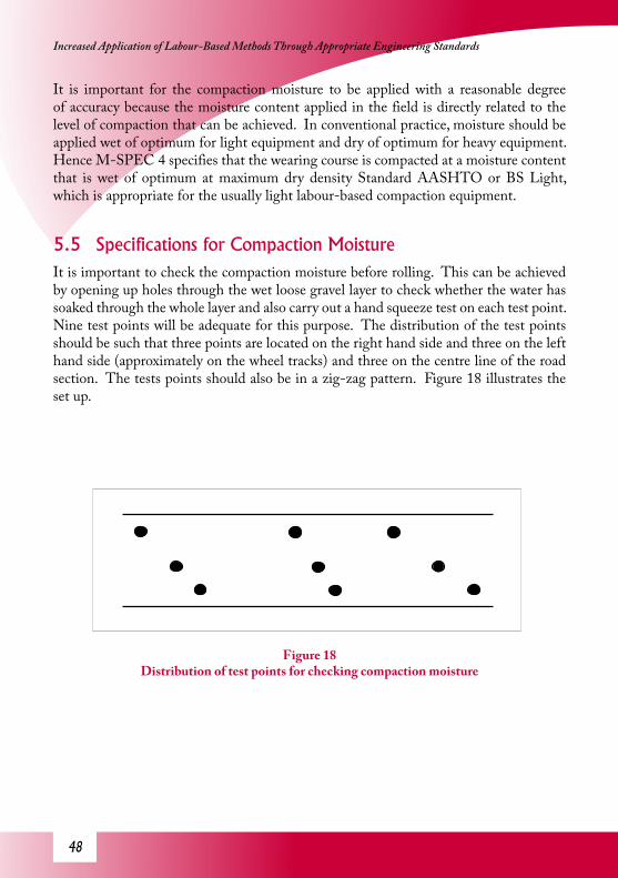
4�
Increased Application of Labour-Based Methods Through Appropriate Engineering Standards
It is important for the compaction moisture to be applied with a reasonable degree of accuracy because the moisture content applied in the field is directly related to the level of compaction that can be achieved. In conventional practice, moisture should be applied wet of optimum for light equipment and dry of optimum for heavy equipment. Hence M-SPEC 4 specifies that the wearing course is compacted at a moisture content that is wet of optimum at maximum dry density Standard AASHTO or BS Light, which is appropriate for the usually light labour-based compaction equipment.
5.5 Specifications for Compaction MoistureIt is important to check the compaction moisture before rolling. This can be achieved by opening up holes through the wet loose gravel layer to check whether the water has soaked through the whole layer and also carry out a hand squeeze test on each test point. Nine test points will be adequate for this purpose. The distribution of the test points should be such that three points are located on the right hand side and three on the left hand side (approximately on the wheel tracks) and three on the centre line of the road section. The tests points should also be in a zig-zag pattern. Figure 18 illustrates the set up.
Figure 18 Distribution of test points for checking compaction moisture

4�
Guideline for Quality Assurance Procedures and Specif ications for Labour-Based Road Works
The compaction moisture should be approved on the basis of the specifications given in Table 19.
Table 19 Approval specifications for compaction moisture for wearing course gravel
Item Approval Conditional Approval Reject
Depth of soaking Full depth soaking for ≥ 6 out of 9 test points
Minimum soaking depth ≥ 75% of layer
thickness (1)
Minimum soaking depth < 75% of layer
thickness (*)
Hand squeeze test ≥ 6 out of 9 test points satisfactory
< 6 test points satisfactory but material is non-
cohesive (2)
< 6 test points satisfactory solely due to lack of moisture (*)
* The contractor should be instructed to apply more water and allow for more soaking.
Conditional Approval:
1) Approval is given on the basis that at least 75% of the layer thickness will receive adequate compaction.
2) Approval is given on condition that the soaked depth is ≥ 75%. Non-cohesive material may fail the hand squeeze test even at optimum moisture content.
5.6 Compaction of Wearing Course GravelThe most important aspect regarding gravel compaction is the relationship between the compaction specification and the available equipment on site. Also, the efficiency of compaction depends on the combination of material type and type of roller or compactor. On labour-based road works there is general tendency to use simpler and lighter equipment, the most common being the smooth-wheeled vibratory rollers. The pedestrian and sit-on 0.8 – 1.7 ton rollers are preferred (Figure 19). The methodologies and specifications detailed below are based on these types of rollers though the principles are applicable to situations where other types of rollers are used.
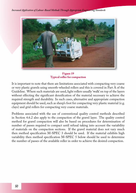
�0
Increased Application of Labour-Based Methods Through Appropriate Engineering Standards
Figure 19Typical roller for compaction
It is important to note that there are limitations associated with compacting very coarse or very plastic gravels using smooth-wheeled rollers and this is covered in Part A of the Guideline. Where such materials are used, light rollers usually ‘walk’ on top of the layers without effecting the significant densification of the material necessary to achieve the required strength and durability. In such cases, alternative and appropriate compaction equipment should be used, such as sheep’s foot for compacting very plastic material (e.g. clays) and grid rollers for compacting very coarse materials.
Problems associated with the use of conventional quality control methods described in Section 4.6.2 also apply to the compaction of the gravel layer. The quality control method for gravel compaction will also be based on procedures for determination of number of passes required to compact until refusal taking into account the variability of materials on the compaction sections. If the gravel material does not vary much then method specification M-SPEC 3 should be used. If the material exhibits high variability then method specification M-SPEC 5 below should be used to determine the number of passes of the available roller in order to achieve the desired compaction.
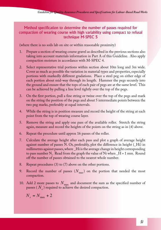
�1
Guideline for Quality Assurance Procedures and Specif ications for Labour-Based Road Works
Method specification to determine the number of passes required for compaction of wearing course with high variability using compact to refusal
technique M-SPEC 5
(where there is no soils lab on site or within reasonable proximity)
1. Prepare a section of wearing course gravel as described in the previous sections also taking into account materials information in Part A of this Guideline. Also apply compaction moisture in accordance with M-SPEC 4.
2. Select representative trial portions within section about 10m long and 3m wide. Cover as much as possible the variation in material types and properties, especially portions with markedly different gradations. Place a steel peg on either edge of each portion about mid-way through its length. Hammer the pegs securely into the ground and ensure that the tops of each pair of pegs are at the same level. This can be achieved by pulling a line level tightly over the top of the pegs.
3. On the first portion, pull a fine string or twine over the top of the pegs and mark on the string the position of the pegs and about 5 intermediate points between the two peg marks, preferably at equal intervals.
4. While the string is in position measure and record the height of the string at each point from the top of wearing course layer.
5. Remove the string and apply one pass of the available roller. Stretch the string again, measure and record the heights of the points on the string as in (4) above.
6. Repeat the procedure until approx 16 passes of the roller.
7. Calculate the average height after each pass and plot a graph of average height against number of passes N. Or, preferably, plot the difference in height (_Hi) in millimetres against passes, where _Hi is the average change in height corresponding to pass number Ni. Read from the graph the value of Ni when _H = 1 mm. Round off the number of passes obtained to the nearest whole number.
8. Repeat procedures (3) to (7) above on the other portions.
9. Record the number of passes ( maxN ) on the portion that needed the most compaction.
10. Add 2 more passes to maxN and document the sum as the specified number of passes ( sN ) required to achieve the desired compaction.
2max += NN s
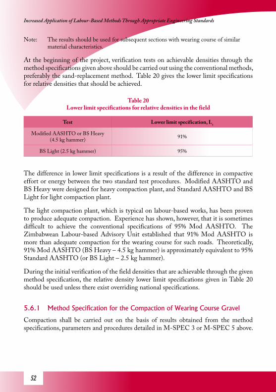
�2
Increased Application of Labour-Based Methods Through Appropriate Engineering Standards
Note: The results should be used for subsequent sections with wearing course of similar material characteristics.
At the beginning of the project, verification tests on achievable densities through the method specifications given above should be carried out using the conventional methods, preferably the sand-replacement method. Table 20 gives the lower limit specifications for relative densities that should be achieved.
Table 20 Lower limit specifications for relative densities in the field
Test Lower limit specification, Ls
Modified AASHTO or BS Heavy (4.5 kg hammer) 91%
BS Light (2.5 kg hammer) 95%
The difference in lower limit specifications is a result of the difference in compactive effort or energy between the two standard test procedures. Modified AASHTO and BS Heavy were designed for heavy compaction plant, and Standard AASHTO and BS Light for light compaction plant.
The light compaction plant, which is typical on labour-based works, has been proven to produce adequate compaction. Experience has shown, however, that it is sometimes difficult to achieve the conventional specifications of 95% Mod AASHTO. The Zimbabwean Labour-based Advisory Unit established that 91% Mod AASHTO is more than adequate compaction for the wearing course for such roads. Theoretically, 91% Mod AASHTO (BS Heavy – 4.5 kg hammer) is approximately equivalent to 95% Standard AASHTO (or BS Light – 2.5 kg hammer).
During the initial verification of the field densities that are achievable through the given method specification, the relative density lower limit specifications given in Table 20 should be used unless there exist overriding national specifications.
5.6.1 Method Specification for the Compaction of Wearing Course Gravel
Compaction shall be carried out on the basis of results obtained from the method specifications, parameters and procedures detailed in M-SPEC 3 or M-SPEC 5 above.

�3
Guideline for Quality Assurance Procedures and Specif ications for Labour-Based Road Works
Method specification for compaction of wearing course, M-SPEC 6
1. The wearing course shall be laid and compacted in layers conforming to approval specifications given in Table 18 and water applied in accordance with M-SPEC 4.
2. The number of passes shall be determined in accordance to M-SPEC 2(i) or M-SPEC 2(ii) –for consistent material or M-SPEC 5 – for non-consistent material.
3. Compaction moisture should be approved in accordance with approval specifications given in Table 19.
4. The most common rollers on labour-based projects are small smooth-wheeled vibratory rollers. It is important to ensure that the roller is in good working order before commencing compaction especially the vibration.
5. Apply the passes starting from the verge or near-side of the carriageway and progress towards the centreline.
6. Ensure that the overlap when passing back and forth is not less than 100 mm and the roller speed is about 0.9 – 1 km/h.
7. Ensure that the edges of the gravel layer are well compacted.
8. When the first pass is completed i.e. from the edge to the centre, carry out the second pass also starting from the edge to the centre.
9. Following the first pass, remove all oversize stone protruding onto the surface of the wearing course and backfill the holes or voids created by so doing with good gravel.
10. Repeat the procedure until the specified number passes (Ns) has been completed.
5.6.2 Specifications for Compaction of Wearing Course
The approval of compaction is dependent on the number of passes applied, the compaction equipment used and whether or not the compaction moisture and layer thickness have
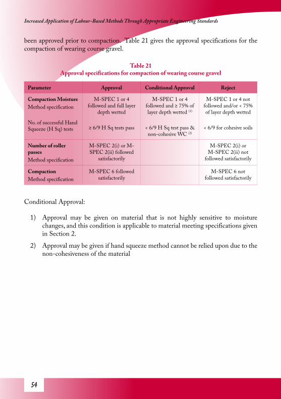
�4
Increased Application of Labour-Based Methods Through Appropriate Engineering Standards
been approved prior to compaction. Table 21 gives the approval specifications for the compaction of wearing course gravel.
Table 21 Approval specifications for compaction of wearing course gravel
Parameter Approval Conditional Approval Reject
Compaction MoistureMethod specification
No. of successful Hand Squeeze (H Sq) tests
M-SPEC 1 or 4 followed and full layer
depth wetted
≥ 6/9 H Sq tests pass
M-SPEC 1 or 4 followed and ≥ 75% of layer depth wetted (1)
< 6/9 H Sq test pass & non-cohesive WC (2)
M-SPEC 1 or 4 not followed and/or < 75% of layer depth wetted
< 6/9 for cohesive soils
Number of roller passesMethod specification
M-SPEC 2(i) or M-SPEC 2(ii) followed
satisfactorily
M-SPEC 2(i) or M-SPEC 2(ii) not
followed satisfactorily
CompactionMethod specification
M-SPEC 6 followed satisfactorily
M-SPEC 6 not followed satisfactorily
Conditional Approval:
1) Approval may be given on material that is not highly sensitive to moisture changes, and this condition is applicable to material meeting specifications given in Section 2.
2) Approval may be given if hand squeeze method cannot be relied upon due to the non-cohesiveness of the material

��
Guideline for Quality Assurance Procedures and Specif ications for Labour-Based Road Works
6 Concrete WorksThe assessment and approval procedures of material ingredients in the production of concrete are covered in detail in Part A of this Guideline. This section covers procedures and approval specifications for concrete works.
There are important aspects to be considered in concrete works when it relates to labour-based activities.
1) In labour-based operations concrete works are carried out by labour alone or labour supported by small machinery.
2) Batching is always carried out by labour.
3) Mixing is carried out by labour or small to medium sized concrete mixers.
4) Transportation is usually carried out with use of wheel barrows.
5) Compaction may be carried out by hand or poker vibrators.
Other activities include site preparation, concrete curing and finishing. In order to ensure good quality concrete, appropriate quality control and operational procedures should be followed. The difficulty with use of conventional methods of quality control is that some of the projects tend to be in remote rural areas and concrete testing facilities and equipment may not be available within economic distances. Setting up testing facilities on site is very costly and in most cases not feasible because equipment such as the hydraulic press for cube crushing needs electricity. There is therefore a need for simpler methods of quality control but nevertheless ensuring that the quality of concrete is not compromised.
6.1 Batching ProcessBatching is a process in the production of concrete where the different constituencies are mixed together in proportions specified in the concrete mix design. The batching process is a potential source of errors and problems which could compromise the quality of concrete. Contamination of the aggregate and/or the concrete itself is a major problem. The other potential problems emanate from errors in proportioning the different constituencies of concrete namely sand, concrete stone, cement and water. A change in aggregate/cement ratio or water/cement ratio can result in significant changes in concrete strength. Fine to coarse aggregate ratio is also important though concrete strength is less sensitive to this parameter. The quality control system should take these issues into consideration.
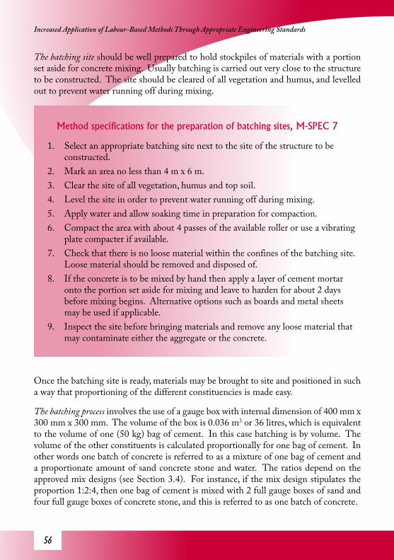
��
Increased Application of Labour-Based Methods Through Appropriate Engineering Standards
The batching site should be well prepared to hold stockpiles of materials with a portion set aside for concrete mixing. Usually batching is carried out very close to the structure to be constructed. The site should be cleared of all vegetation and humus, and levelled out to prevent water running off during mixing.
Method specifications for the preparation of batching sites, M-SPEC 7
1. Select an appropriate batching site next to the site of the structure to be constructed.
2. Mark an area no less than 4 m x 6 m.3. Clear the site of all vegetation, humus and top soil.4. Level the site in order to prevent water running off during mixing.5. Apply water and allow soaking time in preparation for compaction.6. Compact the area with about 4 passes of the available roller or use a vibrating
plate compacter if available.7. Check that there is no loose material within the confines of the batching site.
Loose material should be removed and disposed of.8. If the concrete is to be mixed by hand then apply a layer of cement mortar
onto the portion set aside for mixing and leave to harden for about 2 days before mixing begins. Alternative options such as boards and metal sheets may be used if applicable.
9. Inspect the site before bringing materials and remove any loose material that may contaminate either the aggregate or the concrete.
Once the batching site is ready, materials may be brought to site and positioned in such a way that proportioning of the different constituencies is made easy.
The batching process involves the use of a gauge box with internal dimension of 400 mm x 300 mm x 300 mm. The volume of the box is 0.036 m3 or 36 litres, which is equivalent to the volume of one (50 kg) bag of cement. In this case batching is by volume. The volume of the other constituents is calculated proportionally for one bag of cement. In other words one batch of concrete is referred to as a mixture of one bag of cement and a proportionate amount of sand concrete stone and water. The ratios depend on the approved mix designs (see Section 3.4). For instance, if the mix design stipulates the proportion 1:2:4, then one bag of cement is mixed with 2 full gauge boxes of sand and four full gauge boxes of concrete stone, and this is referred to as one batch of concrete.

��
Guideline for Quality Assurance Procedures and Specif ications for Labour-Based Road Works
Care should be taken to ensure that, the boxes are filled up and the proportions given in the mixed designs are adhered to. A checker should be engaged in order to ensure that batching is carried out in accordance with the mix design. Approvals should be given for the batching process on the basis that the procedures are followed precisely.
Concrete mixing can be carried out either by labour or machine. On most labour-based projects concrete for small structures is mixed by hand because the volumes of concrete involved are appropriate for hand-mixing. In cases where the volumes of concrete involved are large and hand-mixing is rendered inefficient, concrete mixers should be used. The techniques involved in hand mixing are given in appropriate labour-based technical manuals.
a. Mixing by hand
1) In order to ensure ease and quick mixing of concrete by hand, place the materials in layers starting with sand at the bottom followed by cement and then concrete stone. If a number of batches are to be mixed at once the same order of layers of materials shall be placed on top of the previous batch and so on.
2) Mix thoroughly and then add water and continue to mix until all the aggregate is coated with cement paste and the mix looks consistent. A well mixed concrete exhibits a consistent colour and looks greasy.
3) Ensure that the mixing process takes no more than 15 minutes from the time water is added.
b. Mixing by machine (concrete mixer)
1) Proportion the different materials using gauge boxes as described above (the batching process) in proportions given in the mix designs in Part A.
2) Feed the materials into the concrete mixer starting with concrete stone followed by sand and cement and, finally, water.
3) Using an experienced mixer operator, mix the concrete thoroughly for about 90 seconds. The mixing time may be reduced if the concrete obtained is the same as that mixed for 90 seconds, but no approval should be given for mixing time less than 50 seconds or that stipulated by the manufacturer, whichever is greater.
6.1.1 Batch Mixing
Concrete structures are expensive to construct and maintain, or repair. It is therefore in the best interest of the contractor and client to ensure a high level of workmanship and good quality concrete. Rectifying mistakes in concrete works costs dearly.

��
Increased Application of Labour-Based Methods Through Appropriate Engineering Standards
There are simple conventional methods of quality control which can be employed for this purpose, e.g. the slump test. The cube strength tests involve the used of a hydraulic press, but this may be difficult to obtain on a labour-based project. Other concrete strength tests involve the use of cylinders instead of cubes but the procedures and principles are the same. Details are available in the standard test procedures manuals. Where the facilities are available the standard quality control procedures should be used. However, in this Guideline simpler methods are given and these methods are applicable even in very remote areas.
6.1.2 Specifications for Batch Mixing
Apparatus: a metal cone, a tamping rod, a flat metal plate and a mason’s steel trowel.
The slump test is carried out using an open ended metal cone with a bottom diameter of 200 ± 3 mm and a top diameter of 100 ± 3 mm. The height of the cone should be 300 ± 5 mm and the thickness of the metal may be 1.6 mm or whatever is available. The tamping rod should be made out of steel 16 mm diameter and 600 mm long. The metal plate should be 400 mm x 400 mm and thick enough to be rigid. Usually, these pieces of equipment can be purchased ready made, but in the case where the equipment is not available then it may be manufactured locally as specified above.

��
Guideline for Quality Assurance Procedures and Specif ications for Labour-Based Road Works
Test procedure for the slump test M-SPEC 81. Prior to the test make sure that the walls of the cylinder and the bottom plate
are clean and dry.
2. Collect a sample of concrete from a batch that has been thoroughly mixed and ready for pouring.
3. Place the cone on the metal plate ensuring that it is sitting centrally.
4. Place concrete into the cone to a depth of approximately 75mm.
5. Compact the concrete uniformly with 25 strokes of the tamping rod.
6. The layer should be rodded through its depth.
7. Repeat the same procedure for the second, third and fourth 75mm layers.
8. Level the concrete off at the top of the cone using a trowel. All the mortar which will have leaked out should be cleaned off.
9. Remove the cone from the concrete by lifting it up vertically, slowly and carefully. This will allow the concrete to subside.
10. Place the cone on the metal plate beside the concrete and measure the height difference between the top of the cone and the top of the concrete. Record the measured difference in height as the concrete slump to the nearest 5mm.
11. Discard the sample and prepare for the next test.
Consideration is made of the fact that concrete produced and placed under labour-based works should be more workable in order to get a good mix, especially if the concrete has to be hand mixed and/or hand compacted. Workability can be increased by slightly increasing the water/cement ratio, which in turn increases the fluidity of the concrete en-mass. Table 22 gives acceptable limits on slump tests results.
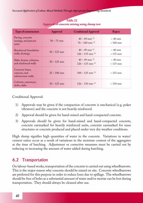
�0
Increased Application of Labour-Based Methods Through Appropriate Engineering Standards
Table 22 Approval of concrete mixing using slump test
Type of construction Approval Conditional Approval Reject
Paving, concrete nosings, and precast units
50 – 75 mm40 – 49 mm (1)
76 – 100 mm (2)
< 40 mm> 100 mm
Reinforced foundation walls, footings. 50 – 125 mm
40 – 49 mm (1)
126 – 135 mm (3)
< 40 mm> 135 mm
Slabs, beams, columns, and reinforced walls 50 – 125 mm
40 – 49 mm (1)
126 – 135 mm (3)
< 40 mm> 135 mm
Concrete bases, caissons, and substructure walls.
25 – 100 mm 100 – 125 mm (3) > 125 mm
Culverts, causeways, drifts, slabs. 50 – 125 mm 126 – 150 mm (3) > 150 mm
Conditional Approval:
1) Approvals may be given if the compaction of concrete is mechanical (e.g. poker vibrators) and the concrete is not heavily reinforced.
2) Approval should be given for hand-mixed and hand-compacted concrete.
3) Approvals should be given for hand-mixed and hand-compacted concrete, concrete earmarked for heavily reinforced units, concrete earmarked for mass structures or concrete produced and placed under very dry weather conditions.
High slump signifies high quantities of water in the concrete. Variations in water/cement ratios occur as a result of variations in the moisture content of the aggregates at the time of batching. Adjustment or corrective measures must be carried out by reducing or increasing the amount of water added during batching.
6.2 TransportationOn labour-based works, transportation of the concrete is carried out using wheelbarrows. This is the major reason why concrete should be mixed on site. Concrete wheelbarrows are preferred for this purpose in order to reduce loses due to spillage. The wheelbarrows should be free of holes as a substantial amount of water and/or mortar can be lost during transportation. They should always be cleaned after use.

�1
Guideline for Quality Assurance Procedures and Specif ications for Labour-Based Road Works
6.3 Placement of ConcreteTransportation and placement should be completed within 30 minutes. Concrete should be placed in layers not exceeding 300 mm if compaction is by hand ramming, and not more than 600 mm if poker vibrators are used. To prevent segregation, concrete should not be poured through a depth exceeding 1.5 m under freefall. Segregation causes serious flaws and localised weakness in the structure which may be detrimental to the performance of the structure itself. In the case where the depth of free fall exceeds 1.5 m wooden or steel funnel chutes should be used. Concrete on all slabs or horizontal structural members should be placed in a continuous pour in order to avoid construction joints. For vertical members, construction joints should be roughened or grooved to ensure bonding between two separate pours.
6.4 Compaction of ConcreteConcrete should be adequately compacted in order to reduce the amount of voids. Voids, when present in large proportions, reduce the strength of the structure or structural element significantly. Compaction can be carried out by hand or by machine (poker vibrators).
Compaction by hand involves the use of tamping or ramming rods. Care should be taken to avoid inadequate or non-uniform compaction. Ramming should be carried out until the top of the concrete appears greasy with cement mortar.
Compaction using poker vibrators is much simpler, quicker and more efficient. It is also important to ensure uniform compaction throughout the whole mass. Compaction should be carried out until there are no air bubbles popping out on the surface of the concrete. Over-compaction should be avoided as segregation may occur. The top of the concrete should be floated to level with a trowel, metal or wooden float or any other tool that may be suitably used.
6.5 Curing of ConcreteCuring is a process of applying moisture onto the surfaces of concrete structures after the concrete has set and under-gone initial hardening. The moisture can be applied by flooding, wet hessian or wet sand cover or any other method as long as the concrete surfaces are kept moist for long periods of time. This activity is a particularly im-portant aspect of concrete works even though it is often overlooked. Concrete gains strength and hardness through hydration, which requires water. If curing is not carried out properly then the concrete close to the surface of the structure will not harden properly because moisture is lost through evaporation. Curing should be carried out for 7 days unless directed otherwise.
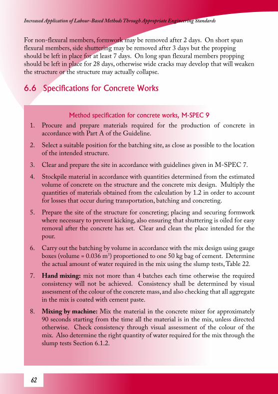
�2
Increased Application of Labour-Based Methods Through Appropriate Engineering Standards
For non-flexural members, formwork may be removed after 2 days. On short span flexural members, side shuttering may be removed after 3 days but the propping should be left in place for at least 7 days. On long span flexural members propping should be left in place for 28 days, otherwise wide cracks may develop that will weaken the structure or the structure may actually collapse.
6.6 Specifications for Concrete Works
Method specification for concrete works, M-SPEC 9
1. Procure and prepare materials required for the production of concrete in accordance with Part A of the Guideline.
2. Select a suitable position for the batching site, as close as possible to the location of the intended structure.
3. Clear and prepare the site in accordance with guidelines given in M-SPEC 7.
4. Stockpile material in accordance with quantities determined from the estimated volume of concrete on the structure and the concrete mix design. Multiply the quantities of materials obtained from the calculation by 1.2 in order to account for losses that occur during transportation, batching and concreting.
5. Prepare the site of the structure for concreting; placing and securing formwork where necessary to prevent kicking, also ensuring that shuttering is oiled for easy removal after the concrete has set. Clear and clean the place intended for the pour.
6. Carry out the batching by volume in accordance with the mix design using gauge boxes (volume = 0.036 m3) proportioned to one 50 kg bag of cement. Determine the actual amount of water required in the mix using the slump tests, Table 22.
7. Hand mixing: mix not more than 4 batches each time otherwise the required consistency will not be achieved. Consistency shall be determined by visual assessment of the colour of the concrete mass, and also checking that all aggregate in the mix is coated with cement paste.
8. Mixing by machine: Mix the material in the concrete mixer for approximately 90 seconds starting from the time all the material is in the mix, unless directed otherwise. Check consistency through visual assessment of the colour of the mix. Also determine the right quantity of water required for the mix through the slump tests Section 6.1.2.

�3
Guideline for Quality Assurance Procedures and Specif ications for Labour-Based Road Works
9. Transport the concrete in concrete wheelbarrows immediately after mixing is complete.
10. Pour the concrete directly into the prepared section of the structure. On construction joints pour cement paste (cement soup) immediately before pouring the concrete. When the depth of pour is ≤ 1.5 m pour concrete directly from the wheelbarrows otherwise use a wooden or steel chute with a funnel at the top to prevent segregation.
11. Steps 7 to 10 should not take more than 30mins.
12. Place concrete in layers ≤ 300 mm for hand compaction or ≤ 600 mm for machine compacted.
13. Hand compaction: use ramming or tamping rods in order to compact concrete through the whole depth of each layer until the surface of the concrete appears oily and shiny with cement paste.
14. Machine compaction: use poker vibrators uniformly through the layer of concrete until there are no more air bubbles popping out on the surface of the concrete.
15. Level the concrete out using steel or wooden floats, and roughen and insert grooves on construction joints where applicable.
16. Where formwork has been placed side shuttering may be removed after 2 days of concrete hardening and after 7 days and 28 days for short span and long span soffits respectively.
17. Apply moisture for curing by flooding, wet hessian, wet sand cover or any other method that allows for prolonged periods of wetting of the concrete surfaces. Cure the concrete for 7 days unless directed otherwise.
18. Plaster all honeycombs if any and carry out concrete finishing where required through rubbing, bullnosing or roughening as stated in the design details.

�4
Increased Application of Labour-Based Methods Through Appropriate Engineering Standards
Figure 20 Loading Frame for Concrete Flexural Tests
Figure 20 shows a loading frame for concrete strength testing. This is a less accurate method compared to the cube strength tests. However, in cases where the latter is not possible flexural strength tests could be used instead and a correlation between the cube strengths and flexural strengths be developed at mix design stage.
The concrete testing equipment consists of two frames; the larger outer frame (the support frame) which should sit level on the ground and the suspendable inner frame (the loading frame). Two half drums are placed in the loading frame. Thick round bars are fixed on top of the support frame, 1m apart. On the upper part of the loading frame is a configuration that transfers two equal point loads 300mm apart on a concrete test beam. This set-up eliminates shear stresses and the concrete beam will fail in bending only.
The weight of the loading frame is predetermined at fabrication stage and once the test has been set up, water is added gradually into the half drums until the test beam fails (breaks). The test should be considered successful if the line of fracture is in between the two loading points.
The procedure for carrying out the test is given in M-SPEC10.
6.6.1 Specifications for Strength Verification
The approval of concrete works is subject to prior approval of material used in the production of concrete (covered in greater detail in Part A of the Guideline). If the materials and concrete mix designs have not been approved then concrete works should

��
Guideline for Quality Assurance Procedures and Specif ications for Labour-Based Road Works
not be allowed to take place. If concreting has been carried out without prior approval then concrete works and the structure, if constructed, should be rejected unless concrete cubes/cylinders have been sampled during construction and strength tests results are satisfactory.
If the materials and concrete mix design have been given approval prior to the concrete works and there are no major variations between materials used in the mix design and those earmarked for the concrete works, then concreting should be approved on the basis of the method specification M-SPEC 9 with infrequent verification tests (method specification M-SPEC 10).

��
Increased Application of Labour-Based Methods Through Appropriate Engineering Standards
Method specification for (a simple) concrete strength verification test M-SPEC 10
1. Procure the necessary apparatus: 6 steel moulds 100 mm (width) x 100 mm (depth) x 1200 mm (length), 25 mm diameter steel tamping rod, and a loading frame.(Figure 20)
2. Collect a sample of concrete from a well mixed batch (one that is ready for pouring).
3. Place the concrete in the mould in 50 mm thick layers.
4. Compact each layer uniformly with a 100 strokes of the metal tamping rod per layer.
5. Level off the top of the concrete with a wooden or steel float and make it as smooth as possible.
6. Keep the cast concrete beam in the mould for 2 days. Immerse in water after the first 24 hours. After 2 days remove the mould and immerse the beam in water for 7 days.
7. Assemble the loading frame and test 3 of the 6 beams for flexural strength. The load is increased by adding water gradually to the drums. The density of water is assumed to be 1 kg/litre for the purpose of this test. For simplicity, all loading is expressed in kilograms.
8. Determine and record the loading when the beam fails, 7L .
9. Test the other 3 beams at 28 days in order to obtain the 28-day strength, L28
10. Obtain the maximum loading (kg) measured on the samples from which the mix design was derived, Ld7 and Ld28.
11. Express the maximum loading obtained on site as percentages of the maximum loading obtained on the mix design samples.
(relative strength at 7 days)

��
Guideline for Quality Assurance Procedures and Specif ications for Labour-Based Road Works
(relative strength at 28 days)
12. Use the results in the approval process given in Table 23.
6.6.2 Specifications for Concrete Works
Table 23 Approval specifications for concrete strength
Item Approval Conditional Approval Reject
Prior approval Approvals available for materials, mix design,
flexural strength at design stage and
concreting procedure
Materials and methodology noted as marginal compared to
approval specifications (1)
Significant departure from approval
specifications (*)
Operations M-SPEC 9 followed satisfactorily
M-SPEC 9 followed satisfactorily with
approved amendments) (2)
M-SPEC 9 not followed and variations
not approved (*)
Relative strength RSC7 ≥ 90%RSC28 ≥ 90%
RSC7 < 90% (3)
RSC28 ≥ 90%RSC7 < 90%RSC28 < 90%
Cube strength (if used)
Average cube strength > specified concrete class (e.g. 20 MPa for C20)+
over-design and all individual cube strengths > specified concrete class
Average cube strength < specified concrete
class +over-design or not all cube strength ≥ specified concrete class
* If the approval specifications or procedures or method specifications given in this Guideline are not followed then alternative methods such as the conventional tests should be used. In the case of concrete, the cube or cylinder strength tests should be carried out in order for approvals to be given.
Conditional Approval:
1) On labour-based works the use of locally available materials is encouraged and that includes the use of screened natural aggregate such as natural stone for coarse aggregate and natural sand. In such cases large variations in materials are bound to occur and concrete works should not be rejected on that basis. If the materials are generally marginal then approval should be given for small structures (smaller than a 1.5 m box culvert).

��
Increased Application of Labour-Based Methods Through Appropriate Engineering Standards
2) The method specification may not be followed satisfactorily due to genuine reasons emanating from environmental or physical constraints on site. Under such circumstances engineering judgement should be used. If the variation or departure from the method specification does not affect the product significantly or if the structure is not very sensitive to such variations then conditional approval should be given. If the structure is sensitive to the variations and the variations are significant enough then compensatory measures should be put in place such as increasing the cement/aggregate ratio in order to increase the strength of the concrete. However, such amendments should be approved by the supervising engineer.
3) The 7-day strength of concrete depends on the rate of chemical reaction (hydration), which is related to the fineness and type of cement. It is possible for concrete to fail the 7-day strength and pass the 28-day strength. If that happens, approval should be given on the basis of the 28-day strength meeting specifications.

��
Guideline for Quality Assurance Procedures and Specif ications for Labour-Based Road Works
PART C – Planning, Design and Life-Cycle Costing
7. Guidelines on Quality Assurance through Planning, Design Processes and Life-Cycle Costing
The quality of a road and the in-service performance is dependent on a holistic approach to road provision and maintenance. It follows therefore that quality assurance should be applied at all stages of road provision from planning to
the end of its life-cycle. A lot of this hinges on the feasibility, planning and design stages. Construction, itself an implementation of plans and designs, only requires good workmanship and management and robust quality control systems. This Guideline would not be complete without the decision processes for appraisals, planning and design procedures. Approval of materials and works is covered in detail in Part A and B. Part C covers appraisal, planning and design procedures and this will complete the package on quality assurance. The procedures below were developed on the basis of results of the analysis of the research data from the Engineering Standards and Whole-Life Costing for Low-Volume Labour-Based and Unpaved Roads Project. A programme was developed with capabilities of estimating/predicting and scheduling of future maintenance requirements and associated life-cycle costs from material properties, traffic and performance based maintenance specifications. This programme is available on the accompanying CD and can be downloaded free from the internet. The programme can be used on new construction and rehabilitation projects and also existing roads under maintenance.
7.1 PlanningQuality assurance should start with the planning process and be implemented at the design and construction stages. Planning involves a decision process in which possible options are considered on the basis of feasibility and costs. The planning process includes:
ü Route planning – on most labour-based road rehabilitation projects the route plan almost always follows the existing road with occasional realignments.
ü Location of sources of materials – especially gravel for wearing course, fill material, selected subgrade, sand etc.
ü Assessment of quality of construction materials available for the project – this involves lab tests and marking off and designating quarries along the route. For gravel wearing course, it is important to carry out sieve analysis and plasticity

�0
Increased Application of Labour-Based Methods Through Appropriate Engineering Standards
tests and determine the Grading Modulus (GM) and Plasticity Product (PP). See Part A.
ü Development of a mass-haul diagram – showing what wearing course material will cover which sections of road.
ü Technology choice – suitability for labour-based construction should be assessed and the appropriate construction technology should be decided upon at this stage.
It is important to ensure that the data collected during the planning stage is of acceptable accuracy because these data will be used in the decision processes for subsequent activities.
It should be noted that planning is a continuous process and reviews should be carried out at regular intervals to ensure that appropriate modifications are implemented timely in order to ensure the quality of output.
7.2 Design and Life-Cycle Costing
7.2.1 Wearing Course Gravel – Quality Classification
Design of low-volume roads especially gravel roads has been over looked in many ways. Most gravel roads have been built without proper designs at all and in some cases the consequences are quite evident in that the roads are costly to maintain. There are cases were the re-gravelling cycles are very short (e.g. less than 6months – coarse limestone gravel road in Ethiopia and less than 1 year on sandy non-plastic wearing course gravel road in Mozambique). This is definitely unsustainable and beyond the capacity of road authorities to re-gravel every year or twice a year. This is often misconstrued as being a result of poor maintenance by responsible authorities as some countries post a net loss in unpaved road networks. This is a typical situation where application of quality assurance at planning and design stages is of paramount importance. This is the reason why Planning and Design have been co-opted in this Guideline. Here quality assurance is meant to ensure good performance of the road in service.
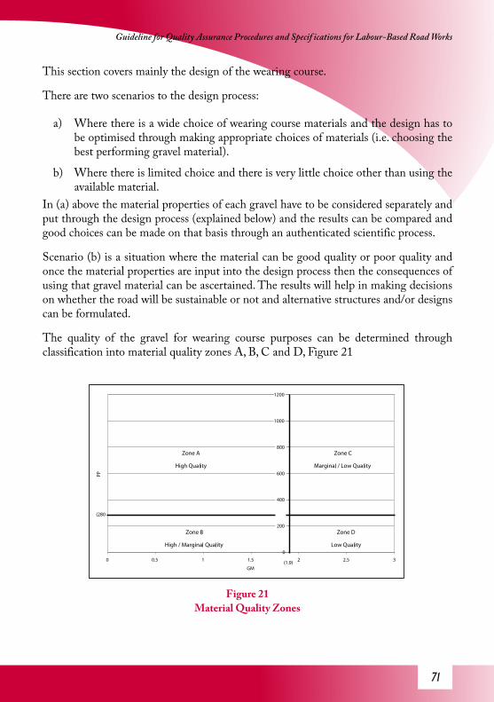
�1
Guideline for Quality Assurance Procedures and Specif ications for Labour-Based Road Works
This section covers mainly the design of the wearing course.
There are two scenarios to the design process:
a) Where there is a wide choice of wearing course materials and the design has to be optimised through making appropriate choices of materials (i.e. choosing the best performing gravel material).
b) Where there is limited choice and there is very little choice other than using the available material.
In (a) above the material properties of each gravel have to be considered separately and put through the design process (explained below) and the results can be compared and good choices can be made on that basis through an authenticated scientific process.
Scenario (b) is a situation where the material can be good quality or poor quality and once the material properties are input into the design process then the consequences of using that gravel material can be ascertained. The results will help in making decisions on whether the road will be sustainable or not and alternative structures and/or designs can be formulated.
The quality of the gravel for wearing course purposes can be determined through classification into material quality zones A, B, C and D, Figure 21
Figure 21Material Quality Zones
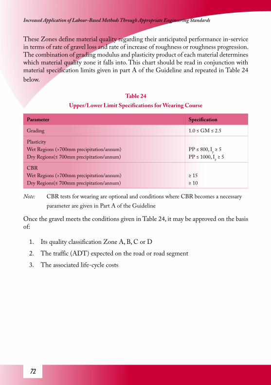
�2
Increased Application of Labour-Based Methods Through Appropriate Engineering Standards
These Zones define material quality regarding their anticipated performance in-service in terms of rate of gravel loss and rate of increase of roughness or roughness progression. The combination of grading modulus and plasticity product of each material determines which material quality zone it falls into. This chart should be read in conjunction with material specification limits given in part A of the Guideline and repeated in Table 24 below.
Table 24 Upper/Lower Limit Specifications for Wearing Course
Parameter Specification
Grading 1.0 ≤ GM ≤ 2.5
Plasticity Wet Regions (>700mm precipitation/annum)Dry Regions(≤ 700mm precipitation/annum)
PP ≤ 800, Ip ≥ 5PP ≤ 1000, Ip ≥ 5
CBRWet Regions (>700mm precipitation/annum)Dry Regions(≤ 700mm precipitation/annum)
≥ 15≥ 10
Note: CBR tests for wearing are optional and conditions where CBR becomes a necessary parameter are given in Part A of the Guideline
Once the gravel meets the conditions given in Table 24, it may be approved on the basis of:
1. Its quality classification Zone A, B, C or D
2. The traffic (ADT) expected on the road or road segment
3. The associated life-cycle costs

�3
Guideline for Quality Assurance Procedures and Specif ications for Labour-Based Road Works
The methodology of material classification is given above. The next stage is to determine the appropriate ADT for the road.
7.1.1 Determination of Design Average Daily Traffic (ADTn)
Basic traffic engineering methods may be used to determine average ADT for the life of the road or performance period. The equation below is used to calculate the design ADT for the life-cycle (n ).
Where:
n = Life-cycle in years
nADT = Design average daily traffic for life-cycle
1ADT = Current average daily traffic
r = Traffic growth rate
Generally a life-cycle of 20 years is assumed but this can be varied in accordance with country standards.
The next stage in the process is to forecast the life-cycle costs.
7.2.3 Life-Cycle Costs Calculations
Life-cycle costs include:
1. Construction cost represented by unit costs (cost/km) for the road or segment of a road. The construction costs can be obtained from the bill of quantities and engineer’s estimates or historical data where none of the former exists.
2. Maintenance costs are derived from existing unit costs and the forecast of maintenance requirements through the life-cycle of the road. The maintenance requirements are derived from the programme described below.
Life-cycle costs are a sum of the construction and maintenance costs. The calculation involves inputting project/road/road segment specific data for the analysis. These data include:

�4
Increased Application of Labour-Based Methods Through Appropriate Engineering Standards
i Currency
ii Gravel thickness (as new)
iii Minimum gravel thickness allowable before re-gravelling is required
iv Life-cycle in years
v Maximum IRI (International Roughness Index) allowable
vi Effect of grading (i.e. change of IRI as a result of a single maintenance grading activity – Default value can be used for this purpose)
vii Cost of construction per km
viii Cost of re-gravelling per km
ix Cost of maintenance grading per km
x Cost of other routine maintenance activities (excluding maintenance grading) per year per km
This Guideline comes with a simple but powerful life-cycle costs calculator which is a mini-programme or software that uses material properties, traffic data, and performance based maintenance specifications, unit costs and other inputs to focus maintenance requirements, compiles all related costs and computes the life-cycle costs.
The inputs are then entered into the appropriate cells in the spreadsheet and software produces instant output. The process is exemplified below.
7.3 Example: Design and Life-Cycle CostingIn this example a new gravel road is earmarked for construction. The planning phase has been completed with all possible gravel quarries demarcated and their locations noted. Laboratory tests have been carried out on samples from these gravel quarries and there are 2 types of wearing course gravel, WC1 and WC2, and the material properties differ significantly in terms of grading modulus and plasticity product. For WC1, GM = 1.4 and PP = 500 and WC2, GM = 2.3 and PP = 90. The current ADT is 70vpd and the traffic growth rate is 5%. Existing specifications require that gravel be place to a thickness of 150mm and the minimum allowable thickness of the gravel layer before re-gravelling becomes necessary should be 25mm. The maximum allowable roughness (IRI) before grading is required is 6m/km. The life-cycle analysis period is 20 years. The currency is denoted in US$. The cost of construction = $15000/km, re-gravelling = $8000/km, maintenance grading = $250/km, other routine maintenance activities = $400/year.
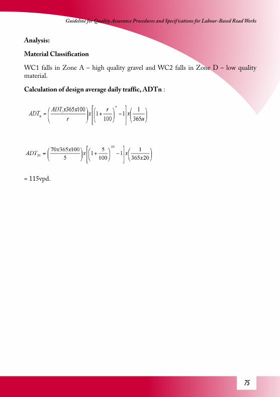
��
Guideline for Quality Assurance Procedures and Specif ications for Labour-Based Road Works
Analysis:
Material Classification
WC1 falls in Zone A – high quality gravel and WC2 falls in Zone D – low quality material.
Calculation of design average daily traffic, ADTn :
= 115vpd.

��
Increased Application of Labour-Based Methods Through Appropriate Engineering Standards Li
fe-c
ycle
cos
ting
Afte
r ent
erin
g th
e inp
uts g
iven
abov
e the
out
puts
will
be as
show
n be
low.
Lif
e-C
ycle
Co
sts
Cal
cula
tor
% 0. 21eta
Rtn uocs iD
$SU
ycne rr uC
mm
051ss enkc ihTre yaLle var
Gm
m52
gn ill ev ar geR ro f
ss en kcih TlevarG
mumin i
Mmkr ep
000 8$S
Ust so
Cg nillevarg e
Rmk rep
0 52$S
Ust so
Cg ni dar
Gry/
mkr ep00 2
$SU
sts oC
e cna ne tn iaM
e nitu oR reht
Omk rep
0$S
Ust so
Cnoit cur tsn o
C lanigirO
sr aey02
d oir ePsis yl anA
elc yC-ef iL
Disc
ount
GL1
00 -
Gra
vel l
oss
per y
ear /
100
AD
TG
Le -
Envi
ronm
enta
l gra
vel l
oss
per y
ear
IRI a
fter R
egra
vellin
g / C
onst
ruct
ion
IRI 1
00 -
Rou
ghne
ss p
rogr
essi
on p
er y
ear /
100
AD
TR
ough
ness
trig
ger f
or G
radi
ngEf
fect
of G
radi
ngTi
me
to 1
st g
radi
ng a
fter r
egra
vellin
g

��
Guideline for Quality Assurance Procedures and Specif ications for Labour-Based Road Works
Zo
ne
A M
ater
ial
12m
m7
mm
3.5
IRI
2.0
IRI
6IR
I1.
5IR
I1.
3ye
ars
Cyc
les
(yea
rs)
No.
in
anal
ysis
perio
d
No.
in
anal
ysis
perio
d(u
ndis
coun
ted)
(dis
coun
ted)
(und
isco
unte
d)(d
isco
unte
d)(u
ndis
coun
ted)
(dis
coun
ted)
(und
isco
unte
d)(d
isco
unte
d)
118
10
00
4000
1442
8000
00
1200
014
425
171
125
00
4000
1442
8000
00
1225
014
4210
171
250
010
740
0014
4280
000
012
500
1548
2016
14
1000
356
4000
1442
8000
00
1300
017
9730
151
615
0047
740
0014
4280
0034
190
1350
053
3840
141
922
5071
940
0014
4280
0034
190
1425
055
8050
131
1127
5096
040
0014
4280
0034
190
1475
058
2160
131
1332
5010
8040
0014
4280
0034
190
1525
059
4170
121
1537
5013
2140
0014
4280
0034
190
1575
061
8280
111
1742
5014
4140
0014
4280
0034
190
1625
063
0290
111
1947
5016
8240
0014
4280
0034
190
1675
065
4310
010
121
5250
1802
4000
1442
8000
3419
017
250
6663
125
92
2665
0022
8340
0014
4216
000
3419
026
500
7144
150
92
3177
5027
6440
0014
4216
000
3419
027
750
7625
175
82
3690
0031
2540
0014
4216
000
3419
029
000
7986
200
72
4010
000
3485
4000
1442
1600
074
660
3000
012
393
250
63
4912
250
4327
4000
1442
2400
074
660
4025
013
234
300
63
5714
250
4928
4000
1442
2400
074
660
4225
013
835
350
53
6416
000
5649
4000
1442
2400
074
660
4400
014
556
400
54
7117
750
6130
4000
1442
3200
011
386
053
750
1895
750
04
582
2050
070
9140
0014
4240
000
1138
60
6450
019
919
CO
STS
Gra
ding
sG
radi
ngO
ther
Rou
tine
ADT
Con
stru
ctio
n
l a to Tg nille va rge
RR
egra
vellin
g

��
Increased Application of Labour-Based Methods Through Appropriate Engineering Standards
Zo
ne
B M
ater
ial
20m
m7
mm
3.5
IRI
2.3
IRI
6IR
I1.
8IR
I1.
1ye
ars
Cyc
les
(yea
rs)
No.
in
anal
ysis
perio
d
No.
in
anal
ysis
perio
d(u
ndis
coun
ted)
(dis
coun
ted)
(und
isco
unte
d)(d
isco
unte
d)(u
ndis
coun
ted)
(dis
coun
ted)
(und
isco
unte
d)(d
isco
unte
d)
118
10
00
4000
1442
8000
00
1200
014
425
161
125
00
4000
1442
8000
00
1225
014
4210
151
250
010
740
0014
4280
000
012
500
1548
2013
14
1000
356
4000
1442
8000
3419
013
000
5217
3011
16
1500
477
4000
1442
8000
3419
013
500
5338
4010
18
2000
719
4000
1442
8000
3419
014
000
5580
509
210
2500
839
4000
1442
1600
034
190
2250
057
0060
82
1230
0010
8040
0014
4216
000
3419
023
000
5941
708
214
3500
1201
4000
1442
1600
034
190
2350
060
6280
72
1640
0013
2140
0014
4216
000
7466
024
000
1022
890
72
1845
0015
6140
0014
4216
000
7466
024
500
1046
910
06
319
4750
1682
4000
1442
2400
074
660
3275
010
589
125
53
2357
5020
4240
0014
4224
000
7466
033
750
1095
015
05
427
6750
2403
4000
1442
3200
011
386
042
750
1523
117
54
430
7500
2644
4000
1442
3200
011
386
043
500
1547
120
04
533
8250
2884
4000
1442
4000
011
386
052
250
1571
225
03
638
9500
3245
4000
1442
4800
015
270
061
500
1995
630
03
741
1025
036
0540
0014
4256
000
1913
90
7025
024
186
350
28
4310
750
3726
4000
1442
6400
023
001
078
750
2816
840
02
944
1100
037
2640
0014
4272
000
2685
80
8700
032
025
500
211
4010
000
3365
4000
1442
8800
030
713
010
2000
3551
9
Gra
ding
sC
OST
Sl at oT
g ni llevar geR
e nit uoR reht
Ogni dar
GR
egra
vellin
g
ADT
Con
stru
ctio
n

��
Guideline for Quality Assurance Procedures and Specif ications for Labour-Based Road Works
Zo
ne
C M
ater
ial
29m
m7
mm
4.0
IRI
4.4
IRI
6IR
I0.
9IR
I0.
5ye
ars
Cyc
les
(yea
rs)
No.
in
anal
ysis
perio
d
No.
in
anal
ysis
perio
d(u
ndis
coun
ted)
(dis
coun
ted)
(und
isco
unte
d)(d
isco
unte
d)(u
ndis
coun
ted)
(dis
coun
ted)
(und
isco
unte
d)(d
isco
unte
d)
117
10
00
4000
1442
8000
00
1200
014
425
151
410
0035
640
0014
4280
000
013
000
1797
1014
19
2250
719
4000
1442
8000
3419
014
250
5580
2011
118
4500
1561
4000
1442
8000
3419
016
500
6422
309
227
6750
2403
4000
1442
1600
034
190
2675
072
6440
82
3587
5031
2540
0014
4216
000
3419
028
750
7986
507
244
1100
039
6640
0014
4216
000
7466
031
000
1287
360
63
5313
250
4687
4000
1442
2400
074
660
4125
013
595
706
361
1525
054
0940
0014
4224
000
7466
043
250
1431
680
53
6917
250
6130
4000
1442
2400
074
660
4525
015
037
905
477
1925
068
5140
0014
4232
000
1138
60
5525
019
678
100
44
8521
250
7572
4000
1442
3200
011
386
057
250
2040
012
54
510
426
000
9255
4000
1442
4000
015
270
070
000
2596
715
03
612
230
500
1081
840
0014
4248
000
1527
00
8250
027
529
175
37
138
3450
012
380
4000
1442
5600
019
139
094
500
3296
120
02
815
438
500
1382
240
0014
4264
000
2300
10
1065
0038
265
250
29
183
4575
016
347
4000
1442
7200
026
858
012
1750
4464
630
02
1120
852
000
1851
040
0014
4288
000
3071
30
1440
0050
664
350
113
229
5725
020
433
4000
1442
1040
0038
417
016
5250
6029
240
01
1524
761
750
2199
640
0014
4212
0000
4226
70
1857
5065
705
500
118
269
6725
023
919
4000
1442
1440
0053
815
021
5250
7917
6
CO
STS
Reg
rave
lling
latoTg ni lle varg e
Renituo
RrehtO
g ni darG
Gra
ding
s
ADT
Con
stru
ctio
n

�0
Increased Application of Labour-Based Methods Through Appropriate Engineering Standards
The
se ar
e the
resu
lts o
f the
com
puta
tion
and
the g
raph
s belo
w ar
e gen
erat
ed au
tom
atica
lly.
Zo
ne
D M
ater
ial
32m
m7
mm
4.5
IRI
9.5
IRI
6IR
I1.
6IR
I0.
2ye
ars
Cyc
les
(yea
rs)
No.
in
anal
ysis
perio
d
No.
in
anal
ysis
perio
d(u
ndis
coun
ted)
(dis
coun
ted)
(und
isco
unte
d)(d
isco
unte
d)(u
ndis
coun
ted)
(dis
coun
ted)
(und
isco
unte
d)(d
isco
unte
d)
117
11
250
040
0014
4280
000
012
250
1442
515
15
1250
477
4000
1442
8000
00
1325
019
1910
131
1127
5096
040
0014
4280
0034
190
1475
058
2120
101
2357
5020
4240
0014
4280
0034
190
1775
069
0430
92
3485
0030
0440
0014
4216
000
3419
028
500
7865
407
246
1150
040
8640
0014
4216
000
7466
031
500
1299
450
63
5714
250
5048
4000
1442
2400
074
660
4225
013
955
606
368
1700
061
3040
0014
4224
000
7466
045
000
1503
770
53
7919
750
7091
4000
1442
2400
074
660
4775
015
999
805
491
2275
081
7340
0014
4232
000
1138
60
5875
021
001
904
410
225
500
9135
4000
1442
3200
011
386
061
500
2196
210
04
511
328
250
1009
640
0014
4240
000
1138
60
7225
022
924
125
36
140
3500
012
500
4000
1442
4800
015
270
087
000
2921
215
03
716
641
500
1490
440
0014
4256
000
1913
90
1015
0035
485
175
28
192
4800
017
308
4000
1442
6400
023
001
011
6000
4175
120
02
921
854
500
1959
240
0014
4272
000
2300
10
1305
0044
034
250
211
268
6700
024
039
4000
1442
8800
030
713
015
9000
5619
330
02
1331
679
000
2836
640
0014
4210
4000
3456
50
1870
0064
373
350
115
362
9050
032
573
4000
1442
1200
0042
267
021
4500
7628
240
01
1740
710
1750
3654
040
0014
4213
6000
4611
70
2417
5084
098
1442
Gra
ding
sC
OST
SR
egra
vellin
gla to T
g nillev argeR
e nituoR re ht
Og ni dar
G
Con
stru
ctio
nAD
T
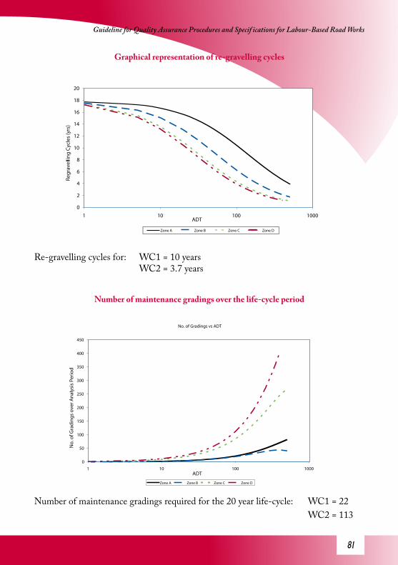
�1
Guideline for Quality Assurance Procedures and Specif ications for Labour-Based Road Works
Graphical representation of re-gravelling cycles
Re-gravelling cycles for: WC1 = 10 years WC2 = 3.7 years
Number of maintenance gradings over the life-cycle period
Number of maintenance gradings required for the 20 year life-cycle: WC1 = 22 WC2 = 113

�2
Increased Application of Labour-Based Methods Through Appropriate Engineering Standards
Life-Cycle Costs
The life-cycle costs for: WC1 = $43,810/km WC2 = $92,213/km
The decision process:
The output from the analysis above clearly shows the difference between wearing course gravels WC1 and WC2. Whereas under non-performance based design or structural design both gravels would be considered equally competent, or WC2 could have been considered to be a better material, this performance based design shows the contrary.
a) If WC1 type gravel is readily available then WC2 should not be used at all. This decision alone can result in more than 50% cost savings.
b) If there is very little of WC1 such that it may only cover a small section of the road under design then it may be worth while considering low-cost sealing, so that the gravel that would otherwise be lost quickly would be protected by the seal or surfacing.

�3
Guideline for Quality Assurance Procedures and Specif ications for Labour-Based Road Works
References
1. Technical Manual, Republic of Kenya, Volume 1, January 1992
2. District Road Works Technical Manual Part 2, Volume 4, 2004, Republic of Uganda, Ministry of Works, Housing and Communications
3. AASHTO Standard Specifications for Transportation Materials and Methods of Sampling and Testing – Part 1 2000
4. AASHTO Standard Specifications for Transportation Materials and Methods of Sampling and Testing – Part 2 2000
5. Materials Testing Manual Part N, Department of Roads, Zimbabwe
6. Materials Specifications Part P, Department of Roads, Zimbabwe
7. SFRDP Research Programme Report, 1989, Swedish Road and Traffic
8. Research Institute(VTI), TRL, Department of Roads – Zimbabwe
9. General Specifications 2001, Rural Feeder Roads Programme, IT Transport/Scott Wilson and Department of Feeder Roads, Ministry of Works, Ghana
10. Standard Specification for Roads and Bridges, 1985, Transvaal Provincial Administration, Roads Department
11. Project Report for the Engineering Standards and Life-Cycle Costing for Labour-Based and Unpaved Roads Research

�4
Increased Application of Labour-Based Methods Through Appropriate Engineering Standards
APPENDIX
FORMS FOR APPROVAL OF MATERIALS
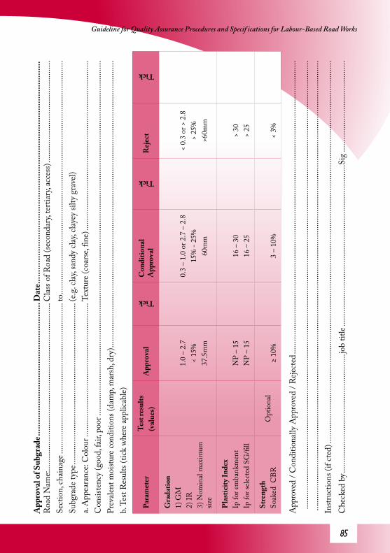
��
Guideline for Quality Assurance Procedures and Specif ications for Labour-Based Road WorksA
ppro
val o
f Sub
grad
e ....
......
......
......
......
......
......
......
......
.....
Dat
e ....
......
......
......
......
......
......
......
......
......
......
......
......
......
......
......
. R
oad
Nam
e: ....
......
......
......
......
......
......
......
......
......
......
......
......
...C
lass o
f Roa
d (se
cond
ary,
terti
ary,
acce
ss) ..
......
......
......
......
......
......
......
....
Sect
ion,
chai
nage
......
......
......
......
......
......
......
......
......
......
......
.....
to ...
......
......
......
......
......
......
......
......
......
......
......
......
......
......
......
......
......
.....
Subg
rade
type
......
......
......
......
......
......
......
......
......
......
......
......
....(
e.g. c
lay, s
andy
clay
, clay
ey si
lty g
rave
l)a.
App
eara
nce:
Col
our .
......
......
......
......
......
......
......
......
......
......
..Te
xtur
e (co
arse
, fin
e) ...
......
......
......
......
......
......
......
......
......
......
......
......
.....
Con
siste
ncy
(goo
d, fa
ir, p
oor .
......
......
......
......
......
......
......
......
......
......
......
......
......
......
......
......
......
......
......
......
......
......
......
......
......
......
......
....
Prev
alent
moi
sture
cond
ition
s (da
mp,
mar
sh, d
ry) ..
......
......
......
......
......
......
......
......
......
......
......
......
......
......
......
......
......
......
......
......
......
......
.b.
Test
Res
ults
(tick
whe
re ap
plica
ble)
Para
met
erTe
st re
sults
(val
ues)
App
rova
l
Tick
Con
ditio
nal
App
rova
l
Tick
Rej
ect
Tick
Gra
datio
n1)
GM
2) IR
3) N
omin
al m
axim
um
size
1.0
– 2.
7<
15%
37.5
mm
0.3
– 1.
0 or
2.7
– 2
.815
% -
25%
60m
m
< 0.
3 or
> 2
.8>
25%
>60m
m
Plas
ticity
Inde
xIp
for e
mba
nkm
ent
Ip fo
r sele
cted
SG
/fill
NP
– 15
NP
– 15
16 –
30
16 –
25
> 30
> 25
Stre
ngth
Soak
ed C
BR
Opt
iona
l≥
10%
3 –
10%
< 3%
App
rove
d / C
ondi
tiona
lly A
ppro
ved
/ Reje
cted
......
......
......
......
......
......
......
......
......
......
......
......
......
......
......
......
......
......
......
......
......
......
......
....
......
......
......
......
......
......
......
......
......
......
......
......
......
......
......
......
......
......
......
......
......
......
......
......
......
......
......
......
......
......
......
......
......
......
...
......
......
......
......
......
......
......
......
......
......
......
......
......
......
......
......
......
......
......
......
......
......
......
......
......
......
......
......
......
......
......
......
......
......
......
..In
struc
tions
(if c
ted)
......
......
......
......
......
......
......
......
......
......
......
......
......
......
......
......
......
......
......
......
......
......
......
......
......
......
......
......
......
......
Che
cked
by .
......
......
......
......
......
......
......
......
......
.job
title
......
......
......
......
......
......
......
......
......
......
......
......
....S
ig ..
......
......
......
......
......
......
.....

��
Increased Application of Labour-Based Methods Through Appropriate Engineering Standards A
ppro
val o
f Wea
ring
Cou
rse .
......
......
......
......
......
......
......
....D
ate .
......
......
......
......
......
......
......
......
......
......
......
......
......
......
......
....
Roa
d N
ame:
......
......
......
......
......
......
......
......
......
......
......
......
......
Clas
s of R
oad
(seco
ndar
y, te
rtiar
y, ac
cess
) .....
......
......
......
......
......
......
......
.Se
ctio
n, ch
aina
ge ...
......
......
......
......
......
......
......
......
......
......
......
..to
......
......
......
......
......
......
......
......
......
......
......
......
......
......
......
......
......
......
..Su
bgra
de ty
pe ...
......
......
......
......
......
......
......
......
......
......
......
......
.(e.g
. clay
, san
dy cl
ay, c
layey
silty
gra
vel)
a. A
ppea
ranc
e: ...
......
......
......
......
......
......
......
......
......
......
......
......
Col
ourT
extu
re ...
......
......
......
......
......
......
......
......
......
......
......
......
......
......
...
(coa
rse,
fine)
……
……
……
. .....
......
......
......
......
......
......
......
......
.Con
siste
ncy
(goo
d, fa
ir, p
oor)
......
......
......
......
......
......
......
......
......
......
......
Prev
alent
moi
sture
cond
ition
s (da
mp,
mar
sh, d
ry) ..
......
......
......
......
......
......
......
......
......
......
......
......
......
......
......
......
......
......
......
......
......
......
. b.
Test
Res
ults
(tick
whe
re ap
plica
ble)
Para
met
erTe
st re
sults
(v
alue
s)A
ppro
val
Tick
Con
ditio
nal
App
rova
l
Tick
Rej
ect
Tick
Gra
datio
n1)
G
M2)
I R
3)
Nom
inal
max
size
1.0
– 1.
9<
10%
25m
m
1.0<
or 2
.0 –
2.5
10%
- 15
%40
mm
< 1.
2 or
> 2
.5>
15%
>40m
m
Plas
ticity
Inde
xI p f
or w
et re
gion
sI p f
or se
mi-a
rid/a
rid
Plas
ticity
Pro
duct
Wet
regi
ons
Dry
regi
ons
10 –
15
10 –
20
280<
PP<8
0028
0<PP
<100
0
5 –
9 or
16
– 20
20 –
27
PP<2
80PP
<280
< 5
or >
20
< 10
or >
27
>800
>100
0
Stre
ngth
CBR
for w
et re
gion
sC
BR fo
r sem
i-arid
/arid
≥ 20
%≥
15%
≥ 15
%≥
10%
< 15
%<
10%
App
rove
d / C
ondi
tiona
lly A
ppro
ved
/ Reje
cted
......
......
......
......
......
......
......
......
......
......
......
......
......
......
......
......
......
......
......
......
......
......
......
Instr
uctio
ns (i
f Reje
cted
) ....
......
......
......
......
......
......
......
......
......
......
......
......
......
......
......
......
......
......
......
......
......
......
......
......
......
......
......
......
.R
emar
ks ...
......
......
......
......
......
......
......
......
......
......
......
......
......
......
......
......
......
......
......
......
......
......
......
......
......
......
......
......
......
......
......
......
....
Che
cked
by .
......
......
......
......
......
......
......
......
......
.job
title
......
......
......
......
......
......
......
......
......
......
......
......
....S
ig ..
......
......
......
......
......
......
.....

��
Guideline for Quality Assurance Procedures and Specif ications for Labour-Based Road WorksA
ppro
val o
f Coa
rse A
ggre
gate
for C
oncr
ete .
......
......
......
......
Dat
e ....
......
......
......
......
......
......
......
......
......
......
......
......
......
......
......
......
.....
Roa
d N
ame:
......
......
......
......
......
......
......
......
......
......
......
......
......
Clas
s of R
oad
(seco
ndar
y, te
rtiar
y, ac
cess
) .....
......
......
......
......
......
......
......
.Se
ctio
n, ch
aina
ge ...
......
......
......
......
......
......
......
......
......
......
......
..to
......
......
......
......
......
......
......
......
......
......
......
......
......
......
......
......
......
......
..A
ggre
gate
Typ
e ....
......
......
......
......
......
......
......
......
......
......
......
......
......
......
......
......
......
......
......
......
......
......
......
......
......
......
......
......
......
......
..D
escr
iptio
n ....
......
......
......
......
......
......
......
......
......
......
......
......
......
......
......
......
......
......
......
......
......
......
......
......
......
......
......
......
......
......
......
....
Sour
ce
......
......
......
......
......
......
......
......
......
......
......
......
......
......
......
......
......
......
......
......
......
......
......
......
......
......
......
......
......
......
......
......
..
Para
met
erTe
st re
sults
App
rova
l
Tick
Con
ditio
nal
App
rova
l
Tick
Rej
ect
Tick
Gra
ding
Tabl
e 7A
ttach
ed p
lot o
n gr
adin
g en
velo
peG
radi
ng w
ithin
en
velo
peG
radi
ng p
artly
wi
thin
enve
lope
Gra
ding
ou
tside
en
velo
pe
Agg
rega
te st
reng
th fo
r nat
ural
ag
greg
ate
AC
V10
% A
CV
(CSI
R te
st ki
t) or
10%
failu
re cl
aw-h
amm
er te
st
≤ 30
≤ 12
tonn
es≤
10%
10%
– 1
5%
> 30
> 12
tonn
es>
15%
Leve
l of c
onta
min
atio
nV
isual
orSe
dim
enta
tion
test.
Clea
n≤
5%D
irty
5% -
10%
Very
dirt
y>
10%
(Not
e: R
eject
ed ag
greg
ate m
ay b
e use
d if,
whe
n us
ed in
conc
rete
mix
des
ign,
satis
fact
ory
stren
gths
are a
chie
ved)
App
rove
d / C
ondi
tiona
lly A
ppro
ved
/ Reje
cted
......
......
......
......
......
......
......
......
......
......
......
......
......
......
......
......
......
......
......
......
......
......
......
Instr
uctio
ns (i
f reje
cted
) ....
......
......
......
......
......
......
......
......
......
......
......
......
......
......
......
......
......
......
......
......
......
......
......
......
......
......
......
......
..R
emar
ks ...
......
......
......
......
......
......
......
......
......
......
......
......
......
......
......
......
......
......
......
......
......
......
......
......
......
......
......
......
......
......
......
......
....
Che
cked
by .
......
......
......
......
......
......
......
......
......
.Job
Titl
e ....
......
......
......
......
......
......
......
......
......
......
......
.... S
ig ..
......
......
......
......
......
......
....

��
Increased Application of Labour-Based Methods Through Appropriate Engineering Standards A
ppro
val o
f Fin
e Agg
rega
te fo
r Con
cret
e ....
......
......
......
......
Dat
e ....
......
......
......
......
......
......
......
......
......
......
......
......
......
......
......
......
.....
Roa
d N
ame:
......
......
......
......
......
......
......
......
......
......
......
......
......
Clas
s of R
oad
(seco
ndar
y, te
rtiar
y, ac
cess
) .....
......
......
......
......
......
......
......
.Se
ctio
n, ch
aina
ge ...
......
......
......
......
......
......
......
......
......
......
......
..to
......
......
......
......
......
......
......
......
......
......
......
......
......
......
......
......
......
......
..A
ggre
gate
Ty
pe ...
......
......
......
......
......
......
......
......
......
......
......
......
......
......
......
......
......
......
......
......
......
......
......
......
......
......
......
......
..
D
escr
iptio
n ...
......
......
......
......
......
......
......
......
......
......
......
......
......
......
......
......
......
......
......
......
......
......
......
......
......
......
...
So
urce
.....
......
......
......
......
......
......
......
......
......
......
......
......
......
......
......
......
......
......
......
......
......
......
......
......
......
......
......
...
Para
met
erTe
st re
sults
App
rova
l
Tick
Con
ditio
nal
App
rova
l
Tick
Rej
ect
Tick
Gra
ding
Tabl
e 8A
ttach
ed p
lot o
n gr
adin
g en
velo
peG
radi
ng w
ithin
en
velo
peG
radi
ng p
artly
wi
thin
enve
lope
Gra
ding
out
side
enve
lope
Leve
lof c
onta
min
atio
nV
isual
and
Sedi
men
tatio
n te
st.C
lean
≤ 5%
Dirt
y5%
- 10
%Ve
ry d
irty
> 10
%
(Not
e: R
eject
ed ag
greg
ate m
ay b
e use
d if,
whe
n us
ed in
conc
rete
mix
des
ign,
satis
fact
ory
stren
gths
are a
chie
ved)
App
rove
d / C
ondi
tiona
lly A
ppro
ved
/ Reje
cted
......
......
......
......
......
......
......
......
......
......
......
......
......
......
......
......
......
......
......
......
......
......
......
Instr
uctio
ns (i
f reje
cted
) ....
......
......
......
......
......
......
......
......
......
......
......
......
......
......
......
......
......
......
......
......
......
......
......
......
......
......
......
......
..R
emar
ks ...
......
......
......
......
......
......
......
......
......
......
......
......
......
......
......
......
......
......
......
......
......
......
......
......
......
......
......
......
......
......
......
......
....
Che
cked
by .
......
......
......
......
......
......
......
......
......
.Job
Titl
e ....
......
......
......
......
......
......
......
......
......
......
......
.... S
ig ..
......
......
......
......
......
......
....

��
Guideline for Quality Assurance Procedures and Specif ications for Labour-Based Road WorksA
ppro
val o
f Wat
er fo
r Con
cret
e ....
......
......
......
......
......
......
..D
ate .
......
......
......
......
......
......
......
......
......
......
......
......
......
......
......
......
......
..R
oad
Nam
e: …
……
……
……
……
……
……
……
……
… ...
....C
lass o
f Roa
d (se
cond
ary,
terti
ary,
acce
ss) ..
......
......
......
......
......
......
......
....
Sect
ion,
chai
nage
......
......
......
......
......
......
......
......
......
......
......
.....
to ...
......
......
......
......
......
......
......
......
......
......
......
......
......
......
......
......
......
.....
Type
of s
truct
ure ..
......
......
......
......
......
......
......
......
......
......
......
......
......
......
......
......
......
......
......
......
......
......
......
......
......
......
......
......
......
......
....
a. A
ppea
ranc
e (cle
ar, t
rans
luce
nt, o
paqu
e) .
......
......
......
......
......
......
......
......
......
......
......
......
......
......
......
......
......
......
......
......
......
......
......
......
. b.
Drin
kabl
e ....
......
......
......
......
......
......
......
......
......
......
......
......
......
......
......
......
......
......
......
......
......
......
......
......
......
......
......
......
......
......
......
...
Para
met
erTe
st re
sults
App
rova
l
Tick
Con
ditio
nal
App
rova
l
Tick
Rej
ect
Tick
Pala
tabi
lity
Drin
kabl
e/N
ot
Drin
kabl
e
Wat
er is
drin
kabl
e
Leve
l of
cont
amin
atio
nV
isual
orTo
tal s
olid
s tes
t.
Wat
er lo
oks C
lean
Wat
er is
tra
nslu
cent
Wat
er is
op
aque
or
mud
dy
(Not
e: A
ppro
val s
houl
d be
giv
en w
ithou
t fur
ther
ado
if th
e wat
er is
drin
kabl
e)
App
rove
d / C
ondi
tiona
lly A
ppro
ved
rejec
ted .
......
......
......
......
......
......
......
......
......
......
......
......
......
......
......
......
......
......
......
......
......
......
......
...In
struc
tions
(if r
eject
ed) .
......
......
......
......
......
......
......
......
......
......
......
......
......
......
......
......
......
......
......
......
......
......
......
......
......
......
......
......
.....
Rem
arks
......
......
......
......
......
......
......
......
......
......
......
......
......
......
......
......
......
......
......
......
......
......
......
......
......
......
......
......
......
......
......
......
......
.C
heck
ed b
y ....
......
......
......
......
......
......
......
......
....Jo
b T
itle .
......
......
......
......
......
......
......
......
......
......
......
......
.Sig
.....
......
......
......
......
......
......
..
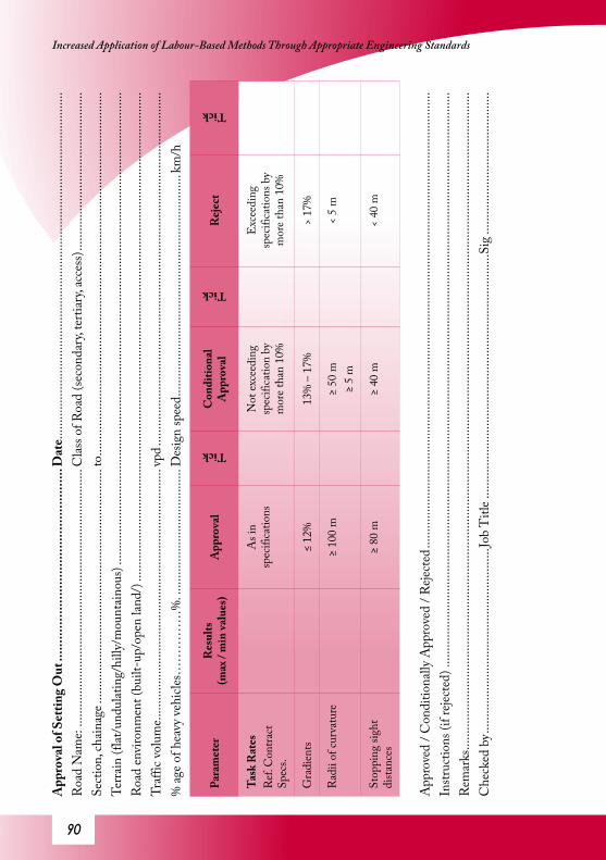
�0
Increased Application of Labour-Based Methods Through Appropriate Engineering Standards A
ppro
val o
f Set
ting
Out
.....
......
......
......
......
......
......
......
......
Dat
e ....
......
......
......
......
......
......
......
......
......
......
......
......
......
......
......
......
.....
Roa
d N
ame:
......
......
......
......
......
......
......
......
......
......
......
......
......
Clas
s of R
oad
(seco
ndar
y, te
rtiar
y, ac
cess
) .....
......
......
......
......
......
......
......
.Se
ctio
n, ch
aina
ge ...
......
......
......
......
......
......
......
......
......
......
......
..to
......
......
......
......
......
......
......
......
......
......
......
......
......
......
......
......
......
......
..Te
rrain
(flat
/und
ulat
ing/
hilly
/mou
ntai
nous
) ....
......
......
......
......
......
......
......
......
......
......
......
......
......
......
......
......
......
......
......
......
......
......
......
.R
oad
envi
ronm
ent (
built
-up/
open
land
/) ...
......
......
......
......
......
......
......
......
......
......
......
......
......
......
......
......
......
......
......
......
......
......
......
......
.Tr
affic
volu
me..
......
......
......
......
......
......
......
......
......
......
......
......
..vp
d ....
......
......
......
......
......
......
......
......
......
......
......
......
......
......
......
......
......
. %
age o
f hea
vy ve
hicle
s……
……
…%
. ....
......
......
......
......
......
....D
esig
n sp
eed .
......
......
......
......
......
......
......
......
......
......
......
km/h
Para
met
erR
esul
ts
(max
/ m
in va
lues
)A
ppro
val
Tick
Con
ditio
nal
App
rova
l
Tick
Rej
ect
Tick
Task
Rat
esR
ef. C
ontra
ct
Spec
s.
As i
n sp
ecifi
catio
nsN
ot ex
ceed
ing
spec
ifica
tion
by
mor
e tha
n 10
%
Exc
eedi
ng
spec
ifica
tions
by
mor
e tha
n 10
%
Gra
dien
ts≤
12%
13%
– 1
7%>
17%
Rad
ii of
curv
atur
e≥
100
m≥
50 m
≥ 5
m<
5 m
Stop
ping
sigh
t di
stanc
es≥
80 m
≥ 40
m<
40 m
App
rove
d / C
ondi
tiona
lly A
ppro
ved
/ Reje
cted
......
......
......
......
......
......
......
......
......
......
......
......
......
......
......
......
......
......
......
......
......
......
......
Instr
uctio
ns (i
f reje
cted
) ....
......
......
......
......
......
......
......
......
......
......
......
......
......
......
......
......
......
......
......
......
......
......
......
......
......
......
......
......
..R
emar
ks ...
......
......
......
......
......
......
......
......
......
......
......
......
......
......
......
......
......
......
......
......
......
......
......
......
......
......
......
......
......
......
......
......
....
Che
cked
by .
......
......
......
......
......
......
......
......
......
.Job
Titl
e ....
......
......
......
......
......
......
......
......
......
......
......
....S
ig ..
......
......
......
......
......
......
.....

�1
Guideline for Quality Assurance Procedures and Specif ications for Labour-Based Road WorksA
ppro
val o
f Bus
h C
lear
ing
......
......
......
......
......
......
......
......
.Dat
e ....
......
......
......
......
......
......
......
......
......
......
......
......
......
......
......
......
.....
Roa
d N
ame:
......
......
......
......
......
......
......
......
......
......
......
......
......
Clas
s of R
oad
(seco
ndar
y, te
rtiar
y, ac
cess
) .....
......
......
......
......
......
......
......
.Se
ctio
n, ch
aina
ge ...
......
......
......
......
......
......
......
......
......
......
......
..to
......
......
......
......
......
......
......
......
......
......
......
......
......
......
......
......
......
......
..
App
rova
l
Tick
Rej
ect
Tick
Bush
es, t
rees
and
tree s
tum
ps
rem
oved
from
with
in ri
ght o
f way
an
d sa
fely
disp
osed
of.
Bush
es p
rese
nt w
ithin
righ
t of w
ay
and/
or n
ot d
ispos
ed o
f pro
perly
App
rove
d / C
ondi
tiona
lly A
ppro
ved
/ Reje
cted
......
......
......
......
......
......
......
......
......
......
......
......
......
......
......
......
......
......
......
......
......
......
......
Instr
uctio
ns (i
f reje
cted
) ....
......
......
......
......
......
......
......
......
......
......
......
......
......
......
......
......
......
......
......
......
......
......
......
......
......
......
......
......
.. ..
......
......
......
......
......
......
......
......
......
......
......
......
......
......
......
......
......
......
......
......
......
......
......
......
......
......
......
......
......
......
......
......
......
......
......
.....
......
......
......
......
......
......
......
......
......
......
......
......
......
......
......
......
......
......
......
......
......
......
......
......
......
......
......
......
......
......
......
......
......
......
...R
emar
ks ...
......
......
......
......
......
......
......
......
......
......
......
......
......
......
......
......
......
......
......
......
......
......
......
......
......
......
......
......
......
......
......
......
....
Che
cked
by .
......
......
......
......
......
......
......
......
......
.Job
Titl
e ....
......
......
......
......
......
......
......
......
......
......
......
....S
ig ..
......
......
......
......
......
......
.....
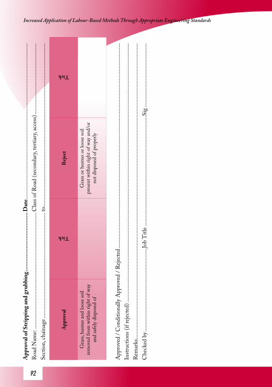
�2
Increased Application of Labour-Based Methods Through Appropriate Engineering Standards A
ppro
val o
f Str
ippi
ng an
d gr
ubbi
ng ...
......
......
......
......
......
...D
ate .
......
......
......
......
......
......
......
......
......
......
......
......
......
......
......
......
......
..R
oad
Nam
e: ...
......
......
......
......
......
......
......
......
......
......
......
......
...C
lass o
f Roa
d (se
cond
ary,
terti
ary,
acce
ss) ..
......
......
......
......
......
......
......
....
Sect
ion,
chai
nage
......
......
......
......
......
......
......
......
......
......
......
.....
to ...
......
......
......
......
......
......
......
......
......
......
......
......
......
......
......
......
......
.....
App
rova
l
Tick
Rej
ect
Tick
Gra
ss, h
umus
and
loos
e soi
l re
mov
ed fr
om w
ithin
righ
t of w
ay
and
safe
ly d
ispos
ed o
f
Gra
ss o
r hum
us o
r loo
se so
il pr
esen
t with
in ri
ght o
f way
and/
or
not d
ispos
ed o
f pro
perly
App
rove
d / C
ondi
tiona
lly A
ppro
ved
/ Reje
cted
......
......
......
......
......
......
......
......
......
......
......
......
......
......
......
......
......
......
......
......
......
......
......
Instr
uctio
ns (i
f reje
cted
) ....
......
......
......
......
......
......
......
......
......
......
......
......
......
......
......
......
......
......
......
......
......
......
......
......
......
......
......
......
..R
emar
ks ...
......
......
......
......
......
......
......
......
......
......
......
......
......
......
......
......
......
......
......
......
......
......
......
......
......
......
......
......
......
......
......
......
....
Che
cked
by .
......
......
......
......
......
......
......
......
......
.Job
Titl
e ....
......
......
......
......
......
......
......
......
......
......
......
....S
ig ..
......
......
......
......
......
......
.....

�3
Guideline for Quality Assurance Procedures and Specif ications for Labour-Based Road WorksA
ppro
val o
f Roa
d-be
d Pr
epar
atio
n ....
......
......
......
......
......
....D
ate .
......
......
......
......
......
......
......
......
......
......
......
......
......
......
......
......
......
..R
oad
Nam
e: ...
......
......
......
......
......
......
......
......
......
......
......
......
...C
lass o
f Roa
d (se
cond
ary,
terti
ary,
acce
ss) ..
......
......
......
......
......
......
......
....
Sect
ion,
chai
nage
......
......
......
......
......
......
......
......
......
......
......
.....
to ...
......
......
......
......
......
......
......
......
......
......
......
......
......
......
......
......
......
.....
Terra
in (f
lat/u
ndul
atin
g/hi
lly/m
ount
aino
us) .
......
......
......
......
......
......
......
......
......
......
......
......
......
......
......
......
......
......
......
......
......
......
......
....
Roa
d en
viro
nmen
t (sw
ampy
/dry
/…) ..
......
......
......
......
......
......
......
......
......
......
......
......
......
......
......
......
......
......
......
......
......
......
......
......
......
...
Para
met
erR
esul
ts
(max
/ m
in
valu
es)
App
rova
l
Tick
Con
ditio
nal A
ppro
val
Tick
Rej
ect
Tick
Ant
hills
Exc
avat
ed an
d tre
ated
to fu
ll de
pth
Exc
avat
ed an
d tre
ated
to
a dep
th >
300
mm
N
ot ex
cava
ted
and
not
treat
ed
Ston
e and
rock
out
crop
sSt
ones
> 5
0mm
re
mov
ed fr
om
right
-of-
way
No
visib
le ro
ck
outc
rops
Roc
k ou
tcro
ps vi
sible
but
≤ 50
mm
(majo
r roa
d)≤
100
mm
(min
or ro
ad)
Roc
k ou
tcro
ps vi
sible
and
> 50
mm
> 10
0 m
m
Roo
tsN
o ro
ots >
50
mm
th
ick vi
sible
Roo
ts >
50 m
m th
ick vi
sible
Com
pact
ion
of fi
ll≥
6 pa
sses
of 1
- 1.
7 to
n vi
brat
ory
rolle
r no
a lay
er ≤
150
mm
th
ick o
r as d
irect
ed
by en
gine
er
≥ 6
pass
es o
f 1 –
1.7
ton
vibr
ator
y ro
ller a
laye
r 15
0 - 1
75 m
m th
ick o
r as
dire
cted
by
the E
ngin
eer
< 6
pass
es o
f 1 -
1.7
ton
vibr
ator
y ro
ller,
or ≥
175
mm
th
ick la
yer
App
rove
d / C
ondi
tiona
lly A
ppro
ved
/ Reje
cted
......
......
......
......
......
......
......
......
......
......
......
......
......
......
......
......
......
......
......
......
......
......
......
...
......
......
......
......
......
......
......
......
......
......
......
......
......
......
......
......
......
......
......
......
......
......
......
......
......
......
......
......
......
......
......
......
......
......
Instr
uctio
ns (i
f reje
cted
) ....
......
......
......
......
......
......
......
......
......
......
......
......
......
......
......
......
......
......
......
......
......
......
......
......
......
......
......
......
..R
emar
ks ...
......
......
......
......
......
......
......
......
......
......
......
......
......
......
......
......
......
......
......
......
......
......
......
......
......
......
......
......
......
......
......
......
....
Che
cked
by .
......
......
......
......
......
......
......
......
......
.Job
Titl
e ....
......
......
......
......
......
......
......
......
......
......
......
....S
ig ..
......
......
......
......
......
......
.....

�4
Increased Application of Labour-Based Methods Through Appropriate Engineering Standards A
ppro
val o
f For
mat
ion
......
......
......
......
......
......
......
......
......
.Dat
e ....
......
......
......
......
......
......
......
......
......
......
......
......
......
......
......
......
.....
Roa
d N
ame:
......
......
......
......
......
......
......
......
......
......
......
......
......
Clas
s of R
oad
(seco
ndar
y, te
rtiar
y, ac
cess
) .....
......
......
......
......
......
......
......
.Se
ctio
n, ch
aina
ge ...
......
......
......
......
......
......
......
......
......
......
......
..to
......
......
......
......
......
......
......
......
......
......
......
......
......
......
......
......
......
......
..
Para
met
erR
esul
ts
(max
/ m
in
valu
es)
App
rova
l
Tick
Con
ditio
nal
App
rova
l
Tick
Rej
ect
Tick
Cro
ss-s
ectio
nal
prof
ilePr
ofile
boa
rd
com
plia
nce c
heck
Prof
ile b
oard
fitti
ng
prop
erly
Prof
ile b
oard
fitti
ng
on ≥
70%
of t
he
tests
Prof
ile b
oard
fitti
ng o
n <
70%
of t
ests
Cam
ber
Rec
omm
ende
d: 8
%Sp
ecifi
ed ±
1%
Spec
ified
± 2
% an
d ac
tual
cam
ber ≥
4%
an
d <
10%
Cam
ber >
10%
,C
ambe
r < 4
%
Dra
in le
vels
• D
irect
ion
of w
ater
flo
w co
rresp
ondi
ng
to lo
catio
n of
wat
er
disc
harg
e stru
ctur
es•
Long
itudi
nal p
rofil
e not
su
scep
tible
to p
ondi
ng
Stor
m-w
ater
will
not
flo
w in
the d
esire
d di
rect
ion
or p
ondi
ng
likel
y to
occ
ur
Thi
ckne
ss o
f C
ompa
cted
Su
bgra
de
New
cons
truc
tion
t avg ≥
tsp
ec –
25m
m
≤
t spec +
25m
mt m
in >
t spec –
35m
m
Upg
radi
ng E
xisti
ng
Ear
th R
oad
t avg <
t spec –
25m
mt m
in <
25m
m (3
)
New
cons
truc
tion
t avg <
t spec –
25m
m
t min
< t sp
ec –
35m
m
App
rove
d / C
ondi
tiona
lly A
ppro
ved
/ Reje
cted
......
......
......
......
......
......
......
......
......
......
......
......
......
......
......
......
......
......
......
......
......
......
......
Instr
uctio
ns (i
f reje
cted
) ....
......
......
......
......
......
......
......
......
......
......
......
......
......
......
......
......
......
......
......
......
......
......
......
......
......
......
......
......
..R
emar
ks ...
......
......
......
......
......
......
......
......
......
......
......
......
......
......
......
......
......
......
......
......
......
......
......
......
......
......
......
......
......
......
......
......
....
Che
cked
by .
......
......
......
......
......
......
......
......
......
.Job
Titl
e ....
......
......
......
......
......
......
......
......
......
......
......
....S
ig ..
......
......
......
......
......
......
.....

��
Guideline for Quality Assurance Procedures and Specif ications for Labour-Based Road WorksA
ppro
val o
f Sub
grad
e Com
pact
ion
......
......
......
......
......
......
.Dat
e……
……
……
……
……
……
….…
… ...
......
......
......
......
......
......
......
Roa
d N
ame:
……
……
……
……
……
……
……
……
……
......
.Clas
s of R
oad
(seco
ndar
y, te
rtiar
y, ac
cess
)……
……
……
……
……
… ...
..Se
ctio
n, ch
aina
ge ...
......
......
......
......
......
......
......
......
......
......
......
..to
......
......
......
......
......
......
......
......
......
......
......
......
......
......
......
......
......
......
..
Para
met
erR
esul
ts
(max
/ m
in va
lues
)A
ppro
val
Tick
Con
ditio
nal
App
rova
l
Tick
Rej
ect
Tick
Com
pact
ion
Moi
stur
e
Met
hod
Spec
ifica
tion
No
of su
cces
sful h
and
sque
eze t
ests
Am
ount
of w
ater
ad
ded
per m
3 of
loos
e soi
l =
……
…lit
res
……
./9
M-S
PEC
1
follo
wed
and
full
layer
dep
th w
ette
d
≥ 6/
9
M-S
PEC
1
follo
wed
and
≥ 75
% o
f lay
er d
epth
we
tted
< 6/
9 fo
r non
-co
hesiv
e soi
l
M-S
PEC
1 n
ot
follo
wed
and/
or <
75
% o
f lay
er d
epth
we
tted
< 6/
9 fo
r coh
esiv
e so
ils
Num
ber o
f rol
ler p
asse
sM
etho
d sp
ecifi
catio
nN
s = …
……
.M
-SPE
C 2
(i)
or M
-SPE
C
2(ii)
follo
wed
satis
fact
orily
M-S
PEC
2(i)
or
M-S
PEC
2(ii
) no
t fol
lowe
d sa
tisfa
ctor
ily
Com
pact
ion
Met
hod
spec
ifica
tion
Na =
……
……
M-S
PEC
3
follo
wed
satis
fact
orily
M-S
PEC
3
not f
ollo
wed
satis
fact
orily
App
rove
d / C
ondi
tiona
lly A
ppro
ved
/ Reje
cted
......
......
......
......
......
......
......
......
......
......
......
......
......
......
......
......
......
......
......
......
......
......
......
Instr
uctio
ns (i
f reje
cted
) ....
......
......
......
......
......
......
......
......
......
......
......
......
......
......
......
......
......
......
......
......
......
......
......
......
......
......
......
......
..R
emar
ks ...
......
......
......
......
......
......
......
......
......
......
......
......
......
......
......
......
......
......
......
......
......
......
......
......
......
......
......
......
......
.C
heck
ed b
y ....
......
......
......
......
......
......
......
......
....Jo
b T
itle .
......
......
......
......
......
......
......
......
......
......
......
......
.Sig
.....
......
......
......
......
......
......
..
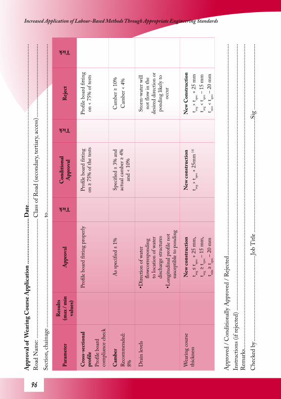
��
Increased Application of Labour-Based Methods Through Appropriate Engineering Standards A
ppro
val o
f W
earin
g C
ours
e App
licat
ion
......
......
......
......
...D
ate .
......
......
......
......
......
......
......
......
......
......
......
......
......
......
......
......
......
..R
oad
Nam
e: ...
......
......
......
......
......
......
......
......
......
......
......
......
...C
lass o
f Roa
d (se
cond
ary,
terti
ary,
acce
ss) ..
......
......
......
......
......
......
......
....
Sect
ion,
chai
nage
......
......
......
......
......
......
......
......
......
......
......
.....
to ...
......
......
......
......
......
......
......
......
......
......
......
......
......
......
......
......
......
.....
Para
met
erR
esul
ts
(max
/ m
in
valu
es)
App
rova
l
Tick
Con
ditio
nal
App
rova
l
Tick
Rej
ect
Tick
Cro
ss-s
ectio
nal
prof
ilePr
ofile
boa
rd
com
plia
nce c
heck
Prof
ile b
oard
fitti
ng p
rope
rlyPr
ofile
boa
rd fi
tting
on
≥ 7
5% o
f the
tests
Prof
ile b
oard
fitti
ng
on <
75%
of t
ests
Cam
ber
Rec
omm
ende
d:
8%
As s
pecif
ied
± 1%
Spec
ified
± 3
% an
d ac
tual
cam
ber ≥
4%
an
d <
10%
Cam
ber ≥
10%
Cam
ber <
4%
Dra
in le
vels
•Dire
ctio
n of
wat
er
flowc
orre
spon
ding
to
loca
tion
of w
ater
di
scha
rge s
truct
ures
•Lon
gitu
dina
l pro
file n
ot
susc
eptib
le to
pon
ding
Stor
m-w
ater
will
no
t flo
w in
the
desir
ed d
irect
ion
or
pond
ing
likel
y to
oc
cur
Wea
ring
cour
se
thick
ness
New
cons
truc
tion
t avg ≤
t spec +
25
mm
,t av
g ≥
t spec
– 15
mm
,t m
in ≥
t spec
– 20
mm
New
cons
truc
tion
t avg >
t spec
+ 25
mm
(4)
New
Con
stru
ctio
nt av
g >
t spec +
25
mm
t avg <
t spec
– 15
mm
t min
< t sp
ec –
20 m
m
App
rove
d / C
ondi
tiona
lly A
ppro
ved
/ Reje
cted
......
......
......
......
......
......
......
......
......
......
......
......
......
......
......
......
......
......
......
......
......
......
......
Instr
uctio
ns (i
f reje
cted
) ....
......
......
......
......
......
......
......
......
......
......
......
......
......
......
......
......
......
......
......
......
......
......
......
......
......
......
......
......
..R
emar
ks ...
......
......
......
......
......
......
......
......
......
......
......
......
......
......
......
......
......
......
......
......
......
......
......
......
......
......
......
......
......
......
......
......
....
Che
cked
by .
......
......
......
......
......
......
......
......
......
.Job
Titl
e ....
......
......
......
......
......
......
......
......
......
......
......
....S
ig ..
......
......
......
......
......
......
.....
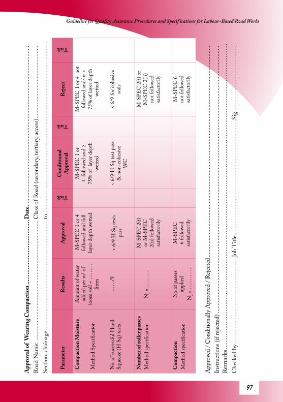
��
Guideline for Quality Assurance Procedures and Specif ications for Labour-Based Road WorksA
ppro
val o
f W
earin
g C
ompa
ctio
n ...
......
......
......
......
......
.....
Dat
e ....
......
......
......
......
......
......
......
......
......
......
......
......
......
......
......
......
.....
Roa
d N
ame:
......
......
......
......
......
......
......
......
......
......
......
......
......
Clas
s of R
oad
(seco
ndar
y, te
rtiar
y, ac
cess
) .....
......
......
......
......
......
......
......
.Se
ctio
n, ch
aina
ge ...
......
......
......
......
......
......
......
......
......
......
......
..to
......
......
......
......
......
......
......
......
......
......
......
......
......
......
......
......
......
......
...
Para
met
erR
esul
tsA
ppro
val
Tick
Con
ditio
nal
App
rova
l
Tick
Rej
ect
Tick
Com
pact
ion
Moi
stur
e
Met
hod
Spec
ifica
tion
No.
of su
cces
sful H
and
Sque
eze (
H S
q) te
sts
Am
ount
of w
ater
ad
ded
per m
3 of
loos
e soi
l = …
……
litre
s
……
/9
M-S
PEC
1 o
r 4
follo
wed
and
full
layer
dep
th w
ette
d
> 6/
9 H
Sq
tests
pa
ss
M-S
PEC
1 o
r 4
follo
wed
and
≥ 75
% o
f lay
er d
epth
we
tted
< 6/
9 H
Sq
test
pass
&
non
-coh
esiv
e W
C
M-S
PEC
1 o
r 4 n
ot
follo
wed
and/
or <
75
% o
f lay
er d
epth
we
tted
< 6/
9 fo
r coh
esiv
e so
ils
Num
ber o
f rol
ler p
asse
sM
etho
d sp
ecifi
catio
nN
s = …
……
.M
-SPE
C 2
(i)
or M
-SPE
C
2(ii)
follo
wed
satis
fact
orily
M-S
PEC
2(i)
or
M-S
PEC
2(ii
) no
t fol
lowe
d sa
tisfa
ctor
ily
Com
pact
ion
Met
hod
spec
ifica
tion
No
of p
asse
s ap
plie
dN
a = …
……
…
M-S
PEC
6
follo
wed
satis
fact
orily
M-S
PEC
6
not f
ollo
wed
satis
fact
orily
App
rove
d / C
ondi
tiona
lly A
ppro
ved
/ Reje
cted
......
......
......
......
......
......
......
......
......
......
......
......
......
......
......
......
......
......
......
......
......
......
......
Instr
uctio
ns (i
f reje
cted
) ....
......
......
......
......
......
......
......
......
......
......
......
......
......
......
......
......
......
......
......
......
......
......
......
......
......
......
......
......
..R
emar
ks ...
......
......
......
......
......
......
......
......
......
......
......
......
......
......
......
......
......
......
......
......
......
......
......
......
......
......
......
......
......
.C
heck
ed b
y ....
......
......
......
......
......
......
......
......
....Jo
b T
itle .
......
......
......
......
......
......
......
......
......
......
......
......
.Sig
.....
......
......
......
......
......
......
..

��
Increased Application of Labour-Based Methods Through Appropriate Engineering Standards A
ppro
val o
f Con
cret
e Wor
ks ...
......
......
......
......
......
......
......
..D
ate…
……
……
……
……
……
……
.……
......
......
......
......
......
......
......
...R
oad
Nam
e: …
……
……
……
……
……
……
……
……
… ...
....C
lass o
f Roa
d (se
cond
ary,
terti
ary,
acce
ss) ..
......
......
......
......
......
......
......
....
Sect
ion,
chai
nage
……
……
......
......
......
...to
……
……
….…
……
……
……
…. ..
......
......
......
......
......
......
......
......
......
......
......
......
......
......
......
Para
met
erR
esul
tsA
ppro
val
Tick
Con
ditio
nal
App
rova
l
Tick
Rej
ect
Tick
Batc
hing
pro
cess
Batc
hing
Site
Pr
epar
atio
n (M
-SPE
C
7) Batc
hing
pro
cess
(M
-SPE
C 8
)
M-S
PEC
7 fo
llowe
d pr
oper
lyM
-SPE
C 8
follo
wed
prop
erly
Am
endm
ents
appr
oved
Am
endm
ents
appr
oved
M-S
PEC
7 n
ot
follo
wed
prop
erly
M-S
PEC
8 n
ot
follo
wed
prop
erly
Con
cret
ing
Ope
ratio
ns (M
-SPE
C 9
)M
-SPE
C 9
follo
wed
prop
erly
Am
endm
ents
appr
oved
M-S
PEC
9 n
ot
follo
wed
prop
erly
Stre
ngth
verif
icat
ion
Flex
ural
stren
gth
tests
(M
-SPE
C 1
0)RS
C7
≥ 90
%RS
C28
≥ 9
0%RS
C7
< 90
%RS
C28
≥ 9
0%RS
C7
< 90
%RS
C28
< 9
0%
Cub
e stre
ngth
(if
use
d)
Ave
rage
cube
stre
ngth
>
spec
ified
conc
rete
cla
ss (e
.g. 2
0 M
Pa fo
r C
20)+
ove
r-de
sign
and
all in
divi
dual
cube
str
engt
hs >
spec
ified
co
ncre
te cl
ass
Ave
rage
cube
stre
ngth
<
spec
ified
conc
rete
cla
ss +
over
-des
ign
or
not a
ll cu
be st
reng
th ≥
sp
ecifi
ed co
ncre
te cl
ass
App
rove
d / C
ondi
tiona
lly A
ppro
ved
/ Reje
cted
......
......
......
......
......
......
......
......
......
......
......
......
......
......
......
......
......
......
......
......
......
......
......
Instr
uctio
ns (i
f reje
cted
) ....
......
......
......
......
......
......
......
......
......
......
......
......
......
......
......
......
......
......
......
......
......
......
......
......
......
......
......
......
..R
emar
ks ...
......
......
......
......
......
......
......
......
......
......
......
......
......
......
......
......
......
......
......
......
......
......
......
......
......
......
......
......
......
.C
heck
ed b
y ....
......
......
......
......
......
......
......
......
....Jo
b T
itle .
......
......
......
......
......
......
......
......
......
......
......
......
.Sig
.....
......
......
......
......
......
......
..

��
Guideline for Quality Assurance Procedures and Specif ications for Labour-Based Road Works

100
Increased Application of Labour-Based Methods Through Appropriate Engineering Standards

![Massage, reflexology and other manual methods for pain ... on labour pain.pdf · [Intervention Review] Massage, reflexology and other manual methods for pain management in labour](https://img.dokumen.tips/doc/110x75/5e3b456542008b17da0edeab/massage-reflexology-and-other-manual-methods-for-pain-on-labour-painpdf.jpg)