Embed Size (px)
Citation preview

4© Crown copyr�ght 2008
AAIB Bulletin: 1/2008 TF-CSB EW/C2006/06/05
INCIDENT
Aircraft Type and Registration: Dorn�er 328 �00, TF-CSB
No & Type of Engines: 2 Pratt and Wh�tney ��9B turboprop eng�nes
Year of Manufacture: �997
Date & Time (UTC): 22 June 2006 at �952 hrs
Location: Aberdeen A�rport
Type of Flight: Commerc�al A�r Transport (Passenger)
Persons on Board: Crew - 3 Passengers - �6
Injuries: Crew - None Passengers - None
Nature of Damage: M�nor damage to wheels
Commander’s Licence: A�rl�ne Transport P�lot’s L�cence
Commander’s Age: 62 years
Commander’s Flying Experience: �3,000 hours (of wh�ch 300 were on type) Last 90 days - ��� hours Last 28 days - 64 hours
Information Source: AAIB F�eld Invest�gat�on
Synopsis
Dur�ng the land�ng roll, the crew could not decelerate the aircraft sufficiently because they were unable, repeatedly, to select the power levers �nto the beta range. The a�rcraft overran the runway and the Runway End Safety Area, com�ng to rest some 350 metres beyond the end of the runway. There were no �njur�es. Three Safety Recommendat�ons are made.
History of the flight
The a�rcraft departed Stavanger at �850 hours on a scheduled commercial air transport (passenger) flight to Aberdeen w�th the commander, co-p�lot, one cab�n crew member, and �6 passengers on board. The co‑pilot flew the sector and before descent, he briefed for a radar-vectored v�sual approach to Aberdeen’s
Runway 34. The flight crew obtained ATIS� �nformat�on wh�ch �nd�cated that the surface w�nd was from 300° at 7 kt, v�s�b�l�ty was greater than �0 km, and the lowest cloud was one or two octas2 at �,500 ft. The ATIS descr�bed the runway as be�ng wet along �ts entire length, though the flight crew later recalled that the runway was dry. The approach was flown normally with flaps at 20º; the final approach speed was 121 kt. The crew were v�sual w�th the runway approx�mately n�ne m�les from touchdown, and were cleared by A�r Traffic Control (ATC) for a visual approach on their request.
Footnote
� Automat�c Term�nal Informat�on Serv�ce.2 Or ‘e�ghths’ of the v�s�ble sky covered by cloud.

5© Crown copyr�ght 2008
AAIB Bulletin: 1/2008 TF-CSB EW/C2006/06/05
W�th the a�rcraft approx�mately seven m�les from touchdown, ATC transm�tted that the surface w�nd was from 300° at 5 kt. The co-p�lot then d�sconnected the autopilot and began configuring the aircraft for the approach. Sl�ghtly more than three m�les from touchdown, the flaps were selected to 20º, and the propeller condition levers were set to maximum; the flight crew then completed the ‘F�nal Approach’ checkl�st. The target speed for the final approach was 121 kt, and the aircraft’s speed stab�l�sed at about �20 kt. Approx�mately two m�les from touchdown, the a�rcraft had dev�ated sl�ghtly below the gl�deslope and a ‘soft’ EGPWS3 “GLIDESLOPE” annunc�at�on was generated. The co-p�lot acknowledged the annunciation, re‑confirmed to the commander that he had v�sual contact w�th the runway, and re-establ�shed the a�rcraft on the gl�deslope.
As the a�rcraft descended through 50 ft rad�o alt�tude, the power levers were retarded and the co-p�lot began the flare. The touchdown occurred approximately 530 metres from the runway threshold (w�th approx�mately �,300 metres of runway rema�n�ng) at an a�rspeed of �05 kt. The commander stated later that the touchdown was a l�ttle further along the runway than he would have preferred, but he cons�dered �t to be ent�rely safe. After touchdown, the co-p�lot attempted to select the power levers �nto the beta range. (Select�on of the beta range produces cons�derable decelerat�on, as the propellers ‘d�sc’ and prov�de drag.) The co-p�lot found, however, that he was unable to move the latches on the power levers wh�ch prevent �nadvertent select�on of the beta range below flight idle. In accordance with normal pract�ce for th�s s�tuat�on he advanced and then retarded the power levers aga�n, and made a second attempt to select the beta range, but found that the latches would st�ll not d�sengage.
Footnote
3 Enhanced Ground Prox�m�ty Warn�ng System (EGPWS).
The co-p�lot sa�d to the commander “WE DON’T HAVE
BETAS”. The commander took control, appl�ed heavy brak�ng, and made four further attempts to ach�eve the beta range, each t�me smartly advanc�ng the power levers and then retarding them to the flight idle stop, before attempt�ng to d�sengage the latches. These attempts were also fru�tless. He transm�tted to ATC that the aircraft was in difficulties.
The tower controller act�vated the crash alarm, alert�ng both the a�rport and local author�ty emergency serv�ces by means of an Omn�crash4 system.
As the a�rcraft approached the end of the runway the commander steered the a�rcraft to the left to avo�d coll�d�ng w�th the approach l�ghts and local�ser antenna on the extended runway centrel�ne. The a�rcraft left the end of the runway surface at about 43 kt, and cont�nued across grassy terra�n beyond the runway end. Recogn�s�ng that the a�rcraft had left the runway, the cab�n crew member �nstructed the passengers to adopt the ‘brace’ pos�t�on, and braced herself. As the a�rcraft travelled across the grass, the commander attempted to shut down the eng�nes, but found that the rough r�de made grasp�ng and mov�ng the cond�t�on levers and the�r latches awkward. The eng�nes were shut down and the a�rcraft came to a standst�ll some 350 metres beyond the runway end. The ground spo�lers rema�ned stowed throughout the land�ng roll.
After the a�rcraft had come to rest, the commander made a Publ�c Address (PA) announcement to the passengers, �nstruct�ng them to rema�n seated and expla�n�ng to them that the crew had exper�enced “A STuCk THROTTLE”. The flight crew completed the ‘Shutdown’ checklist and the commander then left the flight deck and entered the Footnote
4 Omn�crash �s a system wh�ch enables s�multaneous telephone commun�cat�on w�th var�ous emergency serv�ces.

6© Crown copyr�ght 2008
AAIB Bulletin: 1/2008 TF-CSB EW/C2006/06/05
passenger cab�n, where he spoke to the passengers about
the �nc�dent.
The a�rcraft susta�ned no apparent damage and all on
board were un�njured. The Rescue and F�re F�ght�ng
Serv�ce (RFFS) attended the a�rcraft and the passengers
d�sembarked normally.
Initial engineering evaluation
The a�rcraft was �n�t�ally exam�ned where �t had come
to rest, �n a grassed area some 350 metres beyond the
end of Runway 34. No obv�ous damage was ev�dent.
Tyre sk�d mark�ngs cons�stent w�th heavy brak�ng on
all four ma�n-wheels were ev�dent, beg�nn�ng towards
the over-run end of the paved surface. These began
close to the centre-l�ne and dev�ated to the r�ght before
dev�at�ng progress�vely to the left. They �nd�cated
that the a�rcraft departed the paved surface close to
the junct�on of Runway 34 w�th Tax�way ‘W’ by the
Runway �9 threshold, travell�ng at an angle to the left
of the centrel�ne. Wheel marks on the grass showed
that the a�rcraft then turned back unt�l �t was travell�ng
parallel with the runway, but significantly to the left of
the extended centrel�ne.
The previous flight
Dur�ng the prev�ous land�ng at Stavanger, the co-p�lot had
experienced difficulties in operating the latches to reduce
below flight idle. He had brought this to the attention of
the commander, who had ass�sted successfully w�th the
select�on. The land�ng had been otherw�se normal and
the a�rcraft decelerated to tax� speed well before the end
of the runway.
Flight Recorders
General
The a�rcraft was equ�pped w�th a sol�d state Fl�ght Data
Recorder (FDR) that was capable of record�ng and reta�n�ng data for a m�n�mum durat�on of 25 hours, and a sol�d state Cockp�t Vo�ce Recorder (CVR) that was capable of record�ng �20 m�nutes of commun�cat�on and amb�ent sound from the cockp�t env�ronment. The recorders were removed and replayed at the AAIB. Data for the incident flight was available from both recorders.
Recorded Data
T�mes quoted are FDR-recorded uTC. Extracts from the CVR are �n “SMALL CAPITALS”. A�rcraft head�ng �s magnet�c, a�rspeed �s knots Cal�brated A�rSpeed (kCAS) and alt�tudes are referenced to alt�tude above mean sea level (amsl) unless otherw�se stated.
Figure 1 provides the salient parameters of the final approach and land�ng. As the a�rcraft passed through 50 ft rad�o alt�tude, the power levers were retarded and the aircraft started to flare; airspeed was 119 kt. The a�rcraft touched down approx�mately 530 metres from the threshold of Runway 34 (approx�mately �,300 metres from the end of the runway), at an a�rspeed of about �05 kt (a ground speed of �09 kt). Almost �mmed�ately the eng�ne torque started to �ncrease (from about 5% to 40%) before rap�dly decreas�ng (F�gure �, po�nt A), at wh�ch po�nt the a�rcraft started to settle on to �ts wheels and the ground speed started to reduce. The eng�ne torque then rap�dly �ncreased and decreased tw�ce �n qu�ck success�on (F�gure �, po�nt B) and the a�rcraft momentar�ly became l�ght on both ma�n gears. Dur�ng the second eng�ne torque �ncrease the co-p�lot sa�d “WE DON’T HAVE BETAS” to wh�ch the commander acknowledged “NO”; the a�rcraft was about 600 metres from the end of the runway and ground speed was about 92 kt.
Ground speed cont�nued to reduce, but eng�ne torque cont�nued to �ncrease. When the a�rcraft was

�© Crown copyright 2008
AAIB Bulletin: 1/2008 TF-CSB EW/C2006/06/05
Figure 1
Salient FDR Parameters

8© Crown copyr�ght 2008
AAIB Bulletin: 1/2008 TF-CSB EW/C2006/06/05
approx�mately �90 metres from the end of the runway �t started to dev�ate from the runway centre l�ne (F�gure �, po�nt C), turn�ng to the left, almost co�nc�dentally the commander adv�sed the tower “WE GOT A PROBLEM” (F�gure �, po�nt D) ; ground speed was about 40 kt and eng�ne torque was at 37%.
When the a�rcraft was approx�mately �50 metres from the end of the runway the eng�ne torque �ncreased and decreased rap�dly aga�n (F�gure �, po�nt E), the a�rcraft became momentar�ly l�ght on both ma�n gears and started to accelerate sl�ghtly. As the a�rcraft overran the end of the runway ground speed was about 43 kt, and �t turned left reach�ng a head�ng of 299º. The a�rcraft then started to turn to the r�ght aga�n and the eng�ne torque �ncreased and decreased tw�ce, �n rap�d success�on, before the commander gave the �nstruct�on to shut down the eng�nes; the a�rcraft was approx�mately 300 metres beyond the end of the runway at the t�me. As the eng�nes ran down the a�rcraft started to decelerate, eventually com�ng to a stop approx�mately 350 metres beyond the end of the runway on a head�ng of 348º. Dur�ng the land�ng the ground spo�lers had rema�ned stowed.
After com�ng to a stop, the commander gave a br�ef to the passengers, dur�ng wh�ch he expla�ned “WE HAD
A STuCk THROTTLE”. ATC adv�sed the crew that the RFFS were on the way and the crew proceeded w�th the shutdown checkl�st. As the crew shut the a�rcraft down, the co-p�lot sa�d “IT WOuLDN’T MOVE”. RFFS personnel then arr�ved and boarded the a�rcraft, dur�ng wh�ch the commander was heard to say “THE PROPS WOuLDN’T
MOVE BACk...I uSED MAxIMuM BRAkING BuT IT JuST
WOuLDN’T HOLD IT SO I SHuTDOWN THE ENGINES AS
WE LEFT THE RuNWAY”. Battery power was removed at �957 hrs at wh�ch t�me the recorders ceased to funct�on.
The power levers and the flight idle baulk
The aircraft’s power levers are fitted with mechanical baulks to prevent �nappropr�ate select�ons. One baulk prevents selection of settings below flight idle unless certa�n cond�t�ons are met. To select sett�ngs below flight idle (after landing or in the event of a rejected takeoff), the pilot must first ensure that the power levers are at the flight idle position, and then pull two latches (one on each power lever) upwards to d�sengage the locks, before retarding the power levers below flight idle �nto the beta range. Further rearward movement of the power levers causes select�on of �ncreas�ng amounts of reverse thrust. The latches are operated w�th the t�ps of the fingers, whilst the palm of the hand rests on (or grasps) the power lever �tself (see F�gure 2).
Landing technique
Both p�lots stated that �t was normal to select the power levers to flight idle just before touchdown, and that select�on of the beta range once the a�rcraft had landed, caused adequate decelerat�on. They stated that �t was unusual to use the a�rcraft brakes on land�ng unt�l a fast tax� speed had been ach�eved.
The company was operat�ng under another organ�sat�on’s Air Operator’s Certificate, and using the relevant operat�ons manual. The operat�ons manual sect�on ent�tled ‘Standard Operating Procedures’ �ncluded the follow�ng remarks �n the sect�on on ‘Landing’:
‘It is vital that the power levers are moved to the flight idle position BEFORE attempting to lift the latches and continue to ground idle. There have been instances of premature lifting of these latches causing the power levers to become jammed. If the power levers are left in flight idle residual torque will exceed 30% and it will be difficult to stop the aircraft without damage. Should this

9© Crown copyr�ght 2008
AAIB Bulletin: 1/2008 TF-CSB EW/C2006/06/05
Figure 2
Power levers and latches
situation arise, the pilot flying should release the latches and push the power levers forward with the flat of his hand. He should then bring the power levers smartly backwards to the flight idle position before attempting to lift the latches and continue to ground idle’.
Follow�ng a fatal acc�dent �n Genoa, Italy, �n �999 (see ‘Prev�ous �nc�dents’ below), two add�t�onal paragraphs were �nserted �nto the a�rplane operat�ng manual.
The first, headed ‘Baulked Landing’ stated:
‘whenever the captain deems it necessary to discontinue landing roll to avoid a catastrophic
situation after touch down, given sufficient runway length is remaining, he may apply the following baulked landing procedure:
POWER levers (both)….……. Set GA TQGA button………………….…..PressT/O config warning…….…….DisregardAccelerate airplane…….…….VREF
Airplane…………………….…Rotate to GA-FD bar (8°)Once airborneGO-AROUND procedure…..Apply
This manoeuvre is an emergency evasive action, and may be practised in the simulator only.’

�0© Crown copyr�ght 2008
AAIB Bulletin: 1/2008 TF-CSB EW/C2006/06/05
Stop prevents pilot from inadvertent selection of a position belowFlight Idle during flight when retarding Power Lever with latch lifted
Location ‘X’ Ground Idle StopFlight Idle Stop
Figure 3
Power Lever Gate
One UK operator of a fleet of Dornier 328 aircraft stated
that their flight crews were routinely trained in this
procedure dur�ng s�mulator tra�n�ng. The operator of
TF-CSB d�d not carry out s�m�lar tra�n�ng.
The second add�t�onal paragraph, headed ‘Power Lever
Gate’, stated:
‘Certification requirements demand means to
prevent inadvertent operation of reverse thrust
and propeller settings below the flight regime.
These means must have a positive lock or stop at
the flight idle position and must require a separate
and distinct operation by the crew to displace the
control from the flight regime.
The power lever gate of the Dornier 328 has been
designed accordingly. For a selection of power
settings below Flight Idle the Power Levers must
be retarded to the Flight Idle position stop first
(Hands off the latches) before the latch handles
are lifted and lower Power Lever settings can be
selected after landing.
Also be aware, that if the Power Levers are not completely retarded to the Flight Idle stop they may be positioned at Location “X” (see Figures 3 and 4). If this occurs the latches cannot be lifted at all and the Power Levers may jam if rearward pressure is on the latches. If the latches are lifted before Flight Idle, the Power Levers cannot be moved beyond the stop shown in the Power Lever Gate thus preventing the selection of Flight Idle and non-flight regimes.
NOTE: If this happens
1. Remove any backpressure on the Power Levers and release the latches completely.
2. Hold the Power Lever only and smartly retard the Lever to Flight Idle.
3. Normal selection to Ground Idle is now possible.
4. If the Power Lever still cannot be moved below the Flight Idle position, the aircraft can be stopped by applying maximum braking while maintaining a wings level attitude.’

��© Crown copyr�ght 2008
AAIB Bulletin: 1/2008 TF-CSB EW/C2006/06/05
Figure 4
Internal v�ew of power lever, gate and latch
Asymmetric use of beta power
Exper�enced Dorn�er 328 p�lots and tra�n�ng p�lots commented that they bel�eved select�on of one eng�ne �n the beta range with the other in flight idle would give rise to difficulty controlling the aircraft in yaw. The Flight Manual makes no prov�s�on for such operat�ons.
Previous incidents
In February �999, a Dorn�er 328 overran the end of Runway 29 at Genoa A�rport, Italy, and came to rest part�ally submerged �n the sea beyond the runway end. There were four fatal�t�es amongst the 3� passengers and crew on board, and two of the occupants susta�ned ser�ous �njur�es. The Ital�an M�n�stry of Infrastructures and Transport carr�ed out an �nvest�gat�on �nto the acc�dent and concluded:
‘the accident…, was caused by the pilot being unable to move the power levers from the flight idle position to the ground idle position and then to the reverse thrust position. The power levers remaining in the flight idle position meant that the propellers kept turning which prevented the aircraft from slowing sufficiently and frustrated the use of the brakes and emergency brake.’
The report made several Safety Recommendat�ons, �nclud�ng:
‘To the Dornier-Fairchild company: if this has not already been done, define an emergency procedure allowing the crew to manage incidents where it is repeatedly impossible to move the power levers from the flight idle position during the period of travel after landing.’

�2© Crown copyr�ght 2008
AAIB Bulletin: 1/2008 TF-CSB EW/C2006/06/05
In July 2004, a Dorn�er 328 crew rejected a takeoff at
Glasgow A�rport when they found that the left eng�ne
power lever would not move forwards through the Fl�ght
Idle pos�t�on. Subsequently, �t would not move rearwards
from the pos�t�on. The CAA �nvest�gat�on stated:
‘Upon restoring the levers into the normal range,
the power lever sometimes cannot be moved past
flight idle. Rectification of this situation is usually
achieved by lubricating the cam.’
The �nspect�on and lubr�cat�on �nterval for the power lever
cam followers was reduced from 4,000 to 2,000 flight
hours. The report concluded that:
‘the hazard is adequately controlled by the actions
stated above.’
Earl�er, �n January 2004, a Dorn�er 328 crew at London
City Airport experienced difficulty moving the No 1
power lever, finding that it could not be moved from the
Fl�ght Idle pos�t�on dur�ng an attempt to take off. The
reporter noted that the latch on the No � power lever
was st�ck�ng �n the up pos�t�on, but could be forced
downwards, allow�ng forward power lever movement.
The operator reported that, follow�ng clean�ng and
lubr�cat�on, the lever operated correctly. The lever, latch,
and cam should be cleaned, �nspected, and lubr�cated
every 4,000 hours, and the operator reported that th�s
�nterval was sat�sfactory. The report concluded that:
‘the hazard is adequately controlled by existing
requirements, procedures and documentation.’
In February 2005, a Dorn�er 328 crew carr�ed out a
baulked land�ng at Southampton A�rport, when the
co‑pilot (who was pilot flying) found that he could not
select ground �dle after touchdown. The baulked land�ng
and subsequent v�sual c�rcu�t and land�ng were w�thout �nc�dent. The CAA report stated that:
‘the airline has introduced a safety instruction detailing how to carry out the correct procedure with the throttle… based on Dornier service information leaflet SI-328-00-067.’
The report concluded that:
‘the hazard is adequately controlled by existing requirements, procedures and documentation.’
Other pilots’ accounts
Exper�enced Dorn�er 328 p�lots and tra�n�ng capta�ns, including one with test flying experience, were �nterv�ewed �n the course of the AAIB �nvest�gat�on. They were all aware of the potent�al for the power levers to jam, and a number of them had exper�enced th�s themselves. In each of these cases, however, further attempts to ach�eve the Ground Idle range had been
successful.
AAIB evaluation of the power levers and latches
An AAIB Inspector, w�th prev�ous exper�ence on turboprop a�rcraft, evaluated the operat�on of the power levers and latches from both p�lot seats. W�th the a�rcraft stat�onary and the eng�nes shut down, the power levers were moved as though after land�ng. On one of ten attempts from the left seat, �t was found �mposs�ble to d�sengage one of the latches.
Further evaluat�on of the manner of operat�on of the latches �nd�cated that w�th rearwards pressure appl�ed to the power lever, cons�derable upwards pressure was
necessary to operate the latch. If the latch was forced upwards �n th�s manner, the power lever was caused to move sl�ghtly forwards as the latch was operated. The

�3© Crown copyr�ght 2008
AAIB Bulletin: 1/2008 TF-CSB EW/C2006/06/05
effort requ�red to force the latch up was cons�derable, and was not ach�evable w�th the palm of the hand rest�ng lightly on the power levers and the tips of the fingers operat�ng the latch.
Operator’s documentation and crew training
Both p�lots had undertaken ground school tra�n�ng w�th an establ�shed uk operator of the a�rcraft type. Dur�ng this training, they had been informed that difficulties had been exper�enced by p�lots attempt�ng to select the power levers below the flight idle position after landing. They had been told that the appropr�ate techn�que �n th�s s�tuat�on was to advance the power levers aga�n, then retard them to the flight idle stop, before making a further attempt to d�sengage the latches.
After th�s �nc�dent the operator prov�ded add�t�onal tra�n�ng to all crews to fam�l�ar�ze them w�th the c�rcumstances of the event and to re-br�ef them on the contents of Dornier 328 Service Information Leaflet SI-328-00-067. Items d�scussed were the event background, the Service Information Leaflet contents and the balked land�ng procedure. Th�s was followed by a pract�cal demonstrat�on of power lever / reverse latch operat�on wh�lst the a�rcraft was on the stand. Th�s has also now been emphas�zed �n the s�mulator tra�n�ng syllabus.
AAIB Special Bulletin S7/2006
As a result of these concerns, �n August 2006 the AAIB publ�shed a Spec�al Bullet�n, S7/2006, publ�c�s�ng the �nc�dent to TF-CSB. The bullet�n conta�ned the follow�ng Safety Recommendat�on:
Safety Recommendation 2006-104
It �s recommended that Avcraft Aerospace GmBH �.I adv�se all operators of Dorn�er 328
turboprop a�rcraft to deta�l procedures, and prov�de adequate tra�n�ng, to ensure that the�r p�lots are able to act appropr�ately �f the beta control range on the power levers cannot be selected after land�ng.
The CAA responded to th�s Safety Recommendat�on as follows:
‘This Recommendation is not addressed to the CAA. However, the recommendation has been acted upon by the CAA and Inspectors, assigned to the UK companies operating Do328 aircraft, have been made fully aware of the issue and will be discussing the incident with the companies as necessary.’
In December 2006 the Type Certificate holder published Temporary Rev�s�on 20-006 to the A�rplane Operat�ng Manual, wh�ch �ntroduced an opt�on of a baulked land�ng, to be carr�ed out at the p�lot’s d�scret�on, �f a power sett�ng below Fl�ght Idle could not be ach�eved. Th�s was supported by the re-�ssue of Fl�ght Ops Informat�on FOI-328-76-0� on �9 December 2006.
Protection of the overrun area
The a�rcraft came to rest 350 metres beyond the end of the runway. CAP �68 ‘Licensing of Aerodromes’ defines a ‘Runway Strip’ as follows:
‘A runway strip is an area enclosing a runway and any associated stopway. Its purpose is to… reduce the risk of damage to an aeroplane running off the runway by providing a graded area which meets specified longitudinal and transverse slopes, and bearing strength requirements...’

�4© Crown copyr�ght 2008
AAIB Bulletin: 1/2008 TF-CSB EW/C2006/06/05
CAP �68 also requ�res the prov�s�on of Runway End Safety Areas (RESAs), which are defined as:
‘intended to minimise risks to aircraft and their occupants when an aeroplane overruns or undershoots a runway’.
Runway 34 at Aberdeen �s a Code 4D runway, accord�ng to the categor�zat�on �n CAP �68. Thus the runway str�p extends 60 metres beyond the runway end. The RESA �s requ�red to extend 90 metres, and recommended to extend 240 metres, beyond the runway end, although CAP �68 �nstructs aerodrome operators to prov�de RESAs of length appropr�ate to the runway and operat�ons on �t, based upon assessment of overrun r�sk and other factors.
The RESA at the end of Runway 34 �s 240 metres long, and the a�rcraft came to rest ��0 metres beyond �ts end �n an area where no protect�on for overrunn�ng a�rcraft �s required or specifically recommended.
Engineering investigation
Description of significant components
The a�rcraft type �s powered by two Pratt and Wh�tney (Canada) PW ��9B eng�nes dr�v�ng Hartzell s�x-bladed, compos�te, revers�ble-p�tch propellers. The a�rcraft �n quest�on was also equ�pped w�th automat�c l�ft spo�lers, although not all Dornier 328s are so fitted. Each engine/propeller comb�nat�on, or powerplant, �s controlled v�a a power lever and a cond�t�on lever, wh�ch are mounted convent�onally on a console between the two flight crew seats. These levers are connected to the propeller and fuel control un�ts �n the nacelles by a system of cables runn�ng �n condu�ts and pass�ng over pulleys. The power levers are offset towards the left flight crew seat, the condition levers towards the right. During flight each power lever operates between the
geometric flight idle position and maximum power
pos�t�on. Latch levers on the forward face of each
power lever must be ra�sed to enable select�on of the
beta (ground �dle) propeller range. Once these latches
are ra�sed, the power levers are free to move further
aft, command�ng a progress�vely lower blade p�tch
angle. Further movement aft causes the levers to
reach the ground �dle pos�t�on. Aft movement beyond
the ground �dle pos�t�on �ncreases power, prov�d�ng
reverse thrust. Th�s movement �nto the reverse thrust
range compresses a spr�ng w�th�n the quadrant wh�ch
prov�des tact�le �nformat�on to the p�lot.
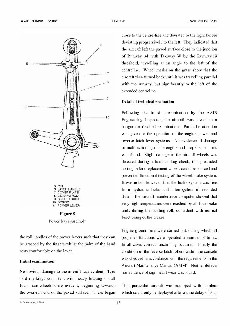
Undesired movement of each power lever from the flight
�dle pos�t�on to the ground �dle pos�t�on �s prevented by
contact between a roller on the lever mechan�sm and a
fixed stop in the console (see Figures 4 and 5). Each
roller �s mounted on a p�n, wh�ch �n turn �s attached to a
fitting on a vertical rod mounted within its power lever.
Each roller moves aft w�th�n a curved track as �ts power
lever is moved backwards, until the flight idle stop is
encountered. Ra�s�ng the latch lever aga�nst spr�ng
pressure l�fts the rod, wh�ch ra�ses the roller clear of
the flight idle stop. This allows the roller and hence
the power lever to move further aft towards the reverse
pos�t�on, the roller travell�ng �n a curved track hav�ng
greater radius than that of the track within the flight
range forward of the flight idle stop position.
The two sections of curved track and the flight idle stop
at each power lever locat�on each take the form of a
cont�nuous shaped cut-out �n one of a pa�r of t�tan�um
alloy plates or�entated �n a vert�cal and long�tud�nal
plane. Each roller �s manufactured from a bronze alloy
and moves w�th�n �ts cut-out form�ng the curved tracks
and the relevant flight idle stop.
The latch levers are pos�t�oned forward of and below
�5© Crown copyr�ght 2008
AAIB Bulletin: 1/2008 TF-CSB EW/C2006/06/05
the roll handles of the power levers such that they can be grasped by the fingers whilst the palm of the hand rests comfortably on the lever.
Initial examination
No obv�ous damage to the a�rcraft was ev�dent. Tyre sk�d mark�ngs cons�stent w�th heavy brak�ng on all four ma�n-wheels were ev�dent, beg�nn�ng towards the over-run end of the paved surface. These began
close to the centre-l�ne and dev�ated to the r�ght before dev�at�ng progress�vely to the left. They �nd�cated that the a�rcraft left the paved surface close to the junct�on of Runway 34 w�th Tax�way W by the Runway �9 threshold, travell�ng at an angle to the left of the centrel�ne. Wheel marks on the grass show that the a�rcraft then turned back unt�l �t was travell�ng parallel with the runway, but significantly to the left of the extended centrel�ne. Detailed technical evaluation
Follow�ng the �n s�tu exam�nat�on by the AAIB Eng�neer�ng Inspector, the a�rcraft was towed to a hangar for deta�led exam�nat�on. Part�cular attent�on was g�ven to the operat�on of the eng�ne power and reverse latch lever systems. No ev�dence of damage or malfunct�on�ng of the eng�ne and propeller controls was found. Sl�ght damage to the a�rcraft wheels was detected dur�ng a hard land�ng check; th�s precluded tax��ng before replacement wheels could be sourced and prevented funct�onal test�ng of the wheel brake system. It was noted, however, that the brake system was free from hydraul�c leaks and �nterrogat�on of recorded data �n the a�rcraft ma�ntenance computer showed that very h�gh temperatures were reached by all four brake un�ts dur�ng the land�ng roll, cons�stent w�th normal funct�on�ng of the brakes.
Eng�ne ground runs were carr�ed out, dur�ng wh�ch all propeller funct�ons were operated a number of t�mes. In all cases correct funct�on�ng occurred. F�nally the cond�t�on of the reverse latch rollers w�th�n the console was checked �n accordance w�th the requ�rements �n the A�rcraft Ma�ntenance Manual (AMM). Ne�ther defects nor evidence of significant wear was found.
Th�s part�cular a�rcraft was equ�pped w�th spo�lers wh�ch could only be deployed after a t�me delay of four
Figure 5
Power lever assembly

�6© Crown copyr�ght 2008
AAIB Bulletin: 1/2008 TF-CSB EW/C2006/06/05
seconds, when both power levers were at or below the flight idle position. Examination of the torque variations recorded on the FDR during the ground roll confirmed that the thrust levers were exerc�sed a number of t�mes. Thus they were not allowed to dwell at a flight idle for sufficiently long to allow the required time delay to elapse. Each forward lever movement cancelled the cycle and requ�red the delay t�me �nterval to beg�n aga�n after the levers were retarded.
From the above exam�nat�on and the assessment of data, �t was concluded that the wheel brakes operated correctly, the propellers d�d not enter the beta range, and the spo�lers, although funct�on�ng correctly, d�d not deploy because the power levers did not remain in flight idle for sufficiently long each time they were retarded.
General comments on power lever and latch design
A fully serv�ceable mechan�cal eng�ne/propeller control system on the type operates sat�sfactor�ly, from a purely mechan�cal po�nt of v�ew, prov�ded all components are undamaged and no significant wear is present �n any of the parts. There was l�ttle wear of the profiled plates in the console and the work‑hardening character�st�cs of t�tan�um alloy from wh�ch they are manufactured, coupled w�th the mater�al propert�es of the soft bronze alloy of the latch rollers wh�ch operate �n contact w�th the plates, ensure that the rollers cannot inflict significant wear damage on the plates. The �nspect�on requ�rement to exam�ne the soft roller mater�al for damage or wear seems to prov�de a su�table yardst�ck for controll�ng and rect�fy�ng the overall wear of the plate/roller comb�nat�on.
Nevertheless the above, difficulties in achieving select�on of beta range after land�ng have been exper�enced, of wh�ch th�s event �s an example. Such problems may occur �f the prec�se angular pos�t�on�ng
of the levers �s not correct at the t�me when attempts are made to l�ft the latches. Incorrect pos�t�on�ng �s thought to be fac�l�tated by ergonom�c features of the power lever/latch lever comb�nat�on. These are accentuated by the fa�rly h�gh degree of fr�ct�on �n the cable/condu�t systems that connect the power levers to the propeller and fuel control un�ts �n the nacelles.
The power levers (F�gure 5) have the�r m�ddle port�ons mach�ned away to form a slot wh�ch accommodates the latch operating mechanism. This modifies the lever structures from act�ng as beams �n bend�ng to resembling portal frames, significantly reducing their bend�ng st�ffness and �ntroduc�ng a sl�ght spr�ng effect �n the�r operat�on. The fr�ct�on �n the operat�ng systems, comb�ned w�th the relat�vely low bend�ng st�ffness of the power levers, can significantly mask the tactile feel of the contact between the rollers and the flight idle stop detents as the levers are retarded.
Ergonomic issues
Cons�der�ng the behav�our of one lever �n �solat�on, correct positioning at the flight idle angle allows the latch to be lifted using the designed finger force, �e solely overcom�ng that created by the latch return spring. Rapid, firm movement of the lever aft to the stop, however, may result in slight flexing of both the lever and parts of the console structure wh�ch can result �n movement of the cable w�th�n the condu�t occurr�ng sl�ghtly beyond the pos�t�on ach�eved �f more gentle movement occurs. Th�s over-travel may be locked �nto the cable by stat�c fr�ct�on effects w�th�n the condu�t and the cable/pulley system.
If the latch �s then l�fted, the roller must travel over a slight projection created by the curved profile of the flight idle stop. The necessary forward movement of the lever to allow th�s �s res�sted by the fr�ct�on �n the cable
�7© Crown copyr�ght 2008
AAIB Bulletin: 1/2008 TF-CSB EW/C2006/06/05
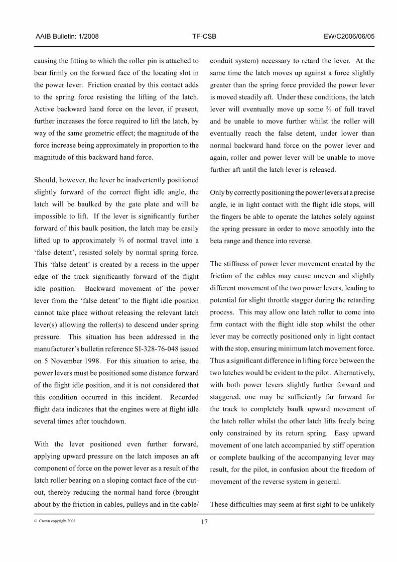
causing the fitting to which the roller pin is attached to bear firmly on the forward face of the locating slot in the power lever. Fr�ct�on created by th�s contact adds to the spr�ng force res�st�ng the l�ft�ng of the latch. Act�ve backward hand force on the lever, �f present, further �ncreases the force requ�red to l�ft the latch, by way of the same geometr�c effect; the magn�tude of the force �ncrease be�ng approx�mately �n proport�on to the magn�tude of th�s backward hand force.
Should, however, the lever be �nadvertently pos�t�oned slightly forward of the correct flight idle angle, the latch w�ll be baulked by the gate plate and w�ll be impossible to lift. If the lever is significantly further forward of th�s baulk pos�t�on, the latch may be eas�ly lifted up to approximately ⅔ of normal travel into a ‘false detent’, res�sted solely by normal spr�ng force. Th�s ‘false detent’ �s created by a recess �n the upper edge of the track significantly forward of the flight �dle pos�t�on. Backward movement of the power lever from the ‘false detent’ to the flight idle position cannot take place w�thout releas�ng the relevant latch lever(s) allow�ng the roller(s) to descend under spr�ng pressure. Th�s s�tuat�on has been addressed �n the manufacturer’s bullet�n reference SI-328-76-048 �ssued on 5 November �998. For th�s s�tuat�on to ar�se, the power levers must be pos�t�oned some d�stance forward of the flight idle position, and it is not considered that th�s cond�t�on occurred �n th�s �nc�dent. Recorded flight data indicates that the engines were at flight idle several t�mes after touchdown.
W�th the lever pos�t�oned even further forward, apply�ng upward pressure on the latch �mposes an aft component of force on the power lever as a result of the latch roller bear�ng on a slop�ng contact face of the cut-out, thereby reduc�ng the normal hand force (brought about by the fr�ct�on �n cables, pulleys and �n the cable/
condu�t system) necessary to retard the lever. At the
same t�me the latch moves up aga�nst a force sl�ghtly
greater than the spr�ng force prov�ded the power lever
�s moved stead�ly aft. under these cond�t�ons, the latch
lever will eventually move up some ⅔ of full travel
and be unable to move further wh�lst the roller w�ll
eventually reach the false detent, under lower than
normal backward hand force on the power lever and
aga�n, roller and power lever w�ll be unable to move
further aft unt�l the latch lever �s released.
Only by correctly pos�t�on�ng the power levers at a prec�se
angle, ie in light contact with the flight idle stops, will
the fingers be able to operate the latches solely against
the spr�ng pressure �n order to move smoothly �nto the
beta range and thence �nto reverse.
The st�ffness of power lever movement created by the
fr�ct�on of the cables may cause uneven and sl�ghtly
d�fferent movement of the two power levers, lead�ng to
potent�al for sl�ght throttle stagger dur�ng the retard�ng
process. Th�s may allow one latch roller to come �nto
firm contact with the flight idle stop whilst the other
lever may be correctly pos�t�oned only �n l�ght contact
w�th the stop, ensur�ng m�n�mum latch movement force.
Thus a significant difference in lifting force between the
two latches would be ev�dent to the p�lot. Alternat�vely,
w�th both power levers sl�ghtly further forward and
staggered, one may be sufficiently far forward for
the track to completely baulk upward movement of
the latch roller wh�lst the other latch l�fts freely be�ng
only constra�ned by �ts return spr�ng. Easy upward
movement of one latch accompan�ed by st�ff operat�on
or complete baulk�ng of the accompany�ng lever may
result, for the p�lot, �n confus�on about the freedom of
movement of the reverse system �n general.
These difficulties may seem at first sight to be unlikely

�8© Crown copyr�ght 2008
AAIB Bulletin: 1/2008 TF-CSB EW/C2006/06/05
to cause an operat�ng problem when v�ewed �n �solat�on. However, �mmed�ately follow�ng an approach and touchdown, w�th the runway end rap�dly approach�ng, the prec�s�on of the act�ons requ�red to place both propellers �n reverse at the same t�me makes th�s a more demand�ng task. The requ�red sequence �nvolves del�cate, accurate movement of levers whose operat�on �s fa�rly st�ff, (accentuated for a p�lot �n the r�ght-hand seat by the offset of the power levers pos�t�on�ng them further from h�s body) followed, often rap�dly, by l�ft�ng of the latches. Ant�c�pat�on of the need for the latter m�ght result �n premature latch l�ft�ng attempts or attempts made when the power levers are not prec�sely pos�t�oned. Th�s poss�b�l�ty �s ass�sted by ergonom�c des�gn features of the latch levers, s�nce they fall eas�ly beneath the fingers of a hand which is placed on the power levers and or�entated �n the opt�mum pos�t�on to retard them. It could become an easy and natural process to squeeze the latch levers as the power �s retarded. Fa�lure to ensure that both levers are pos�t�oned gently against the aft flight idle stop before latch lifting is attempted can lead to st�ff operat�on, asymmetry of latch st�ffness or baulk�ng of one or both latches.
These effects can create the percept�on that jamm�ng �s occurr�ng, even when �t �s not, or actual jamm�ng of one or both latches can occur as a result of a var�ety of these scenar�os.
Alternative Design Approaches
A reverse lever and �nterlock arrangement �s commonly found on turbo-fan powered a�rcraft. To enable reverse operat�on the p�lot must retard the thrust levers fully before transferr�ng h�s hand to the ded�cated reverse levers. These are pos�t�oned as part of the thrust levers but cannot be reached without difficulty until the thrust levers are fully retarded. Once the thrust levers are fully aft, the reverse levers can be grasped and
moved, usually to a detent pos�t�on where an �nterlock prevents the�r further movement unt�l the revers�ng hardware �s correctly pos�t�oned for reverse operat�on and the �nterlock �s released. Thrust can thus only be �ncreased once the thrust revers�ng mechan�sms are �n place. Deliberate difficulty in attempting a continuous movement through �dle thrust to reverse �s created by the des�gned-�n need to change hand pos�t�on dur�ng the process.
Although the process of reverse select�on �n th�s arrangement �s rendered more compl�cated, the chances of acc�dental or premature reverse select�on are much lower.
Such an arrangement �s uncommon on turbo-prop types. Nonetheless, a des�gn change to ach�eve re-or�entat�on, or d�fferent s�z�ng of the latch levers to make �t necessary to repos�t�on the hand, would reduce the poss�b�l�ty of jamm�ng through �ncorrect lever sequenc�ng. Careful des�gn of the pos�t�on and or�entat�on of the latch levers should enable reverse operat�on to be appropr�ately controlled once the power lever has passed �nto the latch release pos�t�on.
Examination of other turbo-prop aircraft types
The power lever controls and revers�ng arrangements of two other a�rcraft types were exam�ned as part of th�s �nvest�gat�on.
Both a�rcraft types were types powered by a pa�r of three spool Pratt and Wh�tney Canada turbo-prop eng�nes of the PW ��9/�25 fam�ly, hav�ng generally s�m�lar requ�rements of the�r control systems to those of the Dornier 328 aircraft. The first type was initially certificated in North America whilst the second was initially certificated in Europe.
�9© Crown copyr�ght 2008
AAIB Bulletin: 1/2008 TF-CSB EW/C2006/06/05
The first type examined had FADEC5 and electr�cally controlled eng�ne and propeller funct�on�ng, obv�at�ng the need for lengthy mechan�cal �nterconnect�ons between power levers and the eng�ne nacelles. Significant friction was thus not present within the operat�ng system other than that created by the manually adjusted fr�ct�on control on the console. The power levers were notably st�ffer �n bend�ng than those on the Dorn�er 328. Operat�on of the levers �n a retard�ng sense thus occurred w�th good tact�le feel. Th�s enabled the flight idle stops to be detected easily when the power levers were symmetr�cally moved aft to that pos�t�on. In a similar manner to the Dornier 328, finger operated latches on each power lever could only be l�fted when the power levers were correctly placed at the fully aft position of the forward range (ie flight idle).
In contrast w�th the arrangement on the Dorn�er, however, the pos�t�on�ng of the hand on the levers to control eng�ne power and to retard the levers dur�ng land�ng, d�ffered significantly from that required to lift the latches. The latches are pos�t�oned d�rectly below the cyl�ndr�cally shaped power lever roll gr�ps and cannot be properly man�pulated by the p�lot unless the hand �s repos�t�oned. The arrangement thus ensures that any tendency to baulk�ng created by apply�ng s�multaneous force to both the levers and the latches �s m�n�m�sed. There �s l�ttle scope for doubt when the levers are at the flight idle pos�t�on, ready for the latches to be l�fted and the levers to be moved further aft �nto reverse.
The other a�rcraft exam�ned had power lever funct�ons connected mechan�cally to the fuel and propeller control un�ts �n the nacelles. Lever fr�ct�on was thus h�gh and of s�m�lar magn�tude to that encountered �n the Dorn�er 328 system. No controllable fr�ct�on dev�ce was therefore necessary or fitted. Footnote5 Full Author�ty D�g�tal Eng�ne Control (FADEC).
In the case of the second a�rcraft type, however, the �n-flight power of each engine was controlled by a dedicated lever, the rearmost pos�t�on of wh�ch co�nc�ded w�th flight idle. Low pitch operation and reversing of each propeller was ach�eved by use of a separate lever mounted on each power lever, �n a manner somewhat s�m�lar to that found on turbofan a�rcraft descr�bed prev�ously. These revers�ng levers were mechan�cally baulked at all power lever angles forward of flight idle. Operation of each revers�ng lever requ�red the correspond�ng power lever to be moved to the aft stop, released and the hand moved phys�cally forward to grasp the roll handles of the reverse levers. Dur�ng exam�nat�on on the ground one negat�ve aspect was noted. If the reverse levers were pulled rearwards when the power lever was forward of the flight idle geometric position, although the reverse lever could not �n�t�ally move, a component of the hand force created by pull�ng �t aga�nst the baulk�ng act�on reacted upon the power lever, dr�v�ng �t rearwards. Th�s enabled it to reach the flight idle position at which point susta�ned force on the revers�ng lever caused �t to move �nto the revers�ng range.
Both the above arrangements prov�de a d�st�nct d�v�s�on between power lever movement and, e�ther movement of the lever �nto the reverse range, or operat�on �n that range. In do�ng so they prov�de the necessary pos�t�ve safeguards aga�nst �nadvertent reverse operat�on �n flight. At the same time they also largely prevent s�multaneous attempts at movement of both levers together dur�ng land�ng, wh�ch can lead to baulk�ng.
The Dorn�er 328 d�ffers from e�ther of these two arrangements �n hav�ng the latch levers pos�t�oned where they can read�ly be pulled upon dur�ng aft power lever movement.

20© Crown copyr�ght 2008
AAIB Bulletin: 1/2008 TF-CSB EW/C2006/06/05
Analysis
There have been a number of events �n wh�ch p�lots have experienced difficulties in selecting ground idle after landing, or other difficulties in moving Dornier 328 power levers. Act�ons taken as a consequence of these events have been to alter the ma�ntenance procedure for the power levers (on the assumpt�on that wear and/or lubr�cat�on �s the cause) or to �nstruct p�lots to alter the�r techn�que.
P�lots have also been tra�ned to deal w�th such a problem after land�ng, w�th one uk operator carry�ng out s�mulator tra�n�ng of �ts crews to enable them to carry out a baulked land�ng (effect�vely, a go-around after the a�rcraft has touched down). Th�s procedure acknowledges that, �f the power levers are not retarded to ground �dle soon after touchdown, �t may not be poss�ble to stop the a�rcraft. Factors g�v�ng r�se to this difficulty include the relatively high thrust of the Dorn�er 328’s powerplants, the rap�d rate at wh�ch �t �s progress�ng along the runway soon after land�ng, and the relat�vely l�m�ted brak�ng capac�ty requ�red by turbopropeller a�rcraft �n general6. The operator of TF-CSB had not carr�ed out th�s tra�n�ng, but �ts operat�ons manual d�d �nstruct p�lots how to deal w�th a power lever jam.
The �nstruct�ons �n the operat�ons manual, to advance and then retard the power levers �n order to resolve a jam, appear, at first sight, to be reasonable. However, there is a tac�t assumpt�on that th�s procedure w�ll be effect�ve, the jam will be cleared, and there will be sufficient runway rema�n�ng on wh�ch to stop the a�rcraft. On a l�m�t�ng runway, th�s may well not be the case, and �f a crew find it necessary to carry out these actions (as did
Footnote
6 The Dornier 328 aircraft meets the relevant certification requ�rements.
the crew of TF-CSB), repeatedly advanc�ng the power levers w�ll add energy to the a�rcraft on each attempt, mak�ng an overrun more l�kely.
The runway at Aberdeen �s longer than many on wh�ch the a�rcraft type typ�cally operates, yet the a�rcraft came to rest beyond the end of the RESA. It was fortunate that th�s add�t�onal area also met the requ�rements of a RESA, although �t was not declared as such. Had the terra�n or obstacles �n th�s area been less ben�gn, the outcome could have been very much more ser�ous.
Follow�ng the acc�dent �n Genoa, two amendments were made to the a�rplane operat�ng manual, one of which identified that it was possible to move the power levers aft, w�th the latches l�fted, unt�l the latch cams were �n ‘Locat�on x’ (F�gure 3). Wh�lst there �s no doubt that th�s pos�t�on �s ach�evable, �t �s also poss�ble that the �nvest�gat�on �nto that acc�dent d�d not �dent�fy the difficulties found in the course of this investigation, and that the difficulties experienced by pilots centre, not around plac�ng the cams �nto ‘Locat�on x’, but around the fr�ct�on and cable forces. Thus, wh�lst techn�cally accurate, the second amendment to the airplane flight manual may have been based upon a false assumpt�on of cause. Therefore the follow�ng add�t�onal Safety Recommendat�on �s made to the Type Certificate holder’s National Airworthiness Authority, the Luftfahrt-Bundesamt (LBA), to m�n�m�se the l�kel�hood of a further, s�m�lar, acc�dent:
Safety Recommendation 2007-103
The Luftfahrt-Bundesamt should ensure that a tra�n�ng programme, fully alert�ng Dorn�er 328 crews to the potent�al for restr�cted movement and the opt�mum operat�on of the lever/latch comb�nat�on, and deta�l�ng appropr�ate operat�onal procedures, be developed and

2�© Crown copyr�ght 2008
AAIB Bulletin: 1/2008 TF-CSB EW/C2006/06/05
mandated for all operators �n Europe, and through l�a�son w�th all relevant Nat�onal Av�at�on Author�t�es, make th�s �nformat�on ava�lable to all operators of the Dorn�er 328 worldw�de.
In the longer term, the des�gn features wh�ch allow the fingers of an average hand to bear comfortably on the revers�ng latches, wh�lst the palm of the hand �s pos�t�oned �n the opt�mum or�entat�on for power regulat�on and reduct�on, should be el�m�nated. Therefore the follow�ng Safety Recommendat�on �s also made:
Safety Recommendation 2007-104
The European Av�at�on Safety Author�ty should requ�re the Dornier 328 Type Certificate holder to re‑design the power lever/beta/reverse latch system to �mprove the present arrangement.
![The Angel of the Annunciation · Annunciation. [12]€Also, the punches used in the diptych divided between St. Petersburg and Washington frequently recur in the Annunciation now](https://img.dokumen.tips/doc/110x75/5fa7155bb84e85719918d5be/the-angel-of-the-annunciation-annunciation-12aalso-the-punches-used-in-the.jpg)