Embed Size (px)
Citation preview
INCH-POUND
MIL-HDBK-1013/1014 MAY 1993SUPERSEDINGSee para 1.2
MILITARY HANDBOOK
DESIGN GUIDELINES FOR SECURITY
FENCING, GATES, BARRIERS, AND GUARD FACILITIES
AMSC N/A AREA FACR
DISTRIBUTION STATEMENT A.UNLIMITED.
APPROVED FOR PUBLIC RELEASE; DISTRIBUTION IS

MIL-HDBK-1013/10
ABSTRACT
This military handbook, MIL-HDBK-1013/10, provides the latest state-of-the-artcriteria for security fencing, gates, barriers, and guard facilities and isprimarily intended for use by Naval Facilities Engineering Command(NAVFACENGCOM) design engineers and architectural and engineering firms. Thecontents cover specific criteria to be used during the selection, design, andconstruction of security fencing, gates, barriers, and guard facilities.
ii

MIL-HDBK-1013/10
FOREWORD
This military handbook has been developed from an evaluation of securityrequirements contained in Department of the Navy and DOD directives, surveysof new materials and construction methods, evaluation and selection of thebest design practices of Naval Facilities Engineering Command (NAVFAC), otherGovernment agencies, and the private sector. It uses national, professional,and other society, association, and institute standards to the maximum extentfeasible. Any deviations from the criteria contained in this handbook for theplanning, engineering, and design of physical security fencing, gates,barriers, and/or guard facilities for Navy shore facilities shall not be madewithout prior approval of NAVFACENGCOM headquarters (Code 04).
Design of security fencing, gates, barriers, and guard facilities does notremain static any more than the functions they serve or the technology theyuse. As such, recommendations for improvement of this handbook are encouragedfrom within the Navy, other Government agencies, and the private sector.Recommendations should be furnished on DD Form 1426 (provided inside the backcover) to the Naval Civil Engineering Laboratory (NCEL), Code L30, 560Laboratory Drive, Port Hueneme, CA 93043-4328, telephone DSN 551-5743, (805)982-5743.
THIS HANDBOOK SHALL NOT BE USED AS A REFERENCE DOCUMENT FOR PROCUREMENT OFFACILITIES CONSTRUCTION. IT IS TO BE USED IN THE PURCHASE OF FACILITIESENGINEERING STUDIES AND DESIGN (FINAL PLANS, SPECIFICATIONS, OR ESTIMATES).DO NOT REFERENCE IT IN MILITARY OR FEDERAL SPECIFICATIONS OR OTHER PROCUREMENTDOCUMENTS.
iii
MIL-HDBK-1013/10
CriteriaManuals
MIL-HDBK-1013/1
DM-13.02
MIL-HDBK-1013/4
MIL-HDBK-1013/5
MIL-HDBK-1013/7
MIL-HDBK-1013/8
MIL-HDBK-1013/10
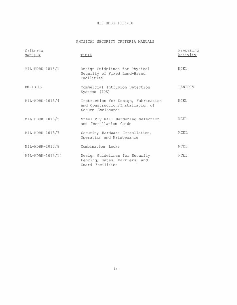
PHYSICAL SECURITY CRITERIA MANUALS
Title
Design Guidelines for PhysicalSecurity of Fixed Land-BasedFacilities
Commercial Intrusion DetectionSystems (IDS)
Instruction for Design, Fabricationand Construction/Installation ofSecure Enclosures
Steel-Ply Wall Hardening Selectionand Installation Guide
Security Hardware Installation,Operation and Maintenance
Combination Locks
Design Guidelines for SecurityFencing, Gates, Barriers, andGuard Facilities
iv
PreparingActivity
NCEL
LANTDIV
NCEL
NCEL
NCEL
NCEL
NCEL

Section 11.11.21.31.41.51.61.71.81.9
Section 22.12.22.2.12.32.3.12.3.22.3.32.3.42.3.52.3.5.12.3.5.22.3.5.32.3.5.42.3.5.52.3.62.3.6.12.3.6.22.3.6.32.3.6.42.3.6.52.3.6.62.3.72.3.82.3.92.4
2.4.12.4.22.4.3
MIL-HDBK-1013/10
DESIGN GUIDELINES FOR SECURITY FENCING, GATES,BARRIERS, AND GUARD FACILITIES
CONTENTS
INTRODUCTIONScope . . . . . . . . . . . . . . . . . . . . . .Cancellation . . . . . . . . . . . . . . . . . . .Criteria Documentation . . . . . . . . . . . . . .Application . . . . . . . . . . . . . . . . . . .Technical Approach for Fence Design . . . . . . .NATO Criteria . . . . . . . . . . . . . . . . . .Preliminary Physical Security Considerations . . .Fencing Modifications . . . . . . . . . . . . . . .Cost of Security . . . . . . . . . . . . . . . . .
FENCESApplication . . . . . . . . . . . . . . . . . . .Related Criteria . . . . . . . . . . . . . . . . .Initial Barrier Design . . . . . . . . . . . . . .Chain-Link Fences . . . . . . . . . . . . . . . .Posts and Bracing . . . . . . . . . . . . . . . .Chain-link Fence Fabric . . . . . . . . . . . . .Outriggers . . . . . . . . . . . . . . . . . . . .Accessories . . . . . . . . . . . . . . . . . . .Erection Requirements . . . . . . . . . . . . . .Fence Placement . . . . . . . . . . . . . . . . .Posts, Top Rails, and Bracing . . . . . . . . . .Chain-Link Fence Fabric Mounting . . . . . . . . .Outriggers . . . . . . . . . . . . . . . . . . . .Accessories . . . . . . . . . . . . . . . . . . .Special Security Features . . . . . . . . . . . .Clear Zones . . . . . . . . . . . . . . . . . . .Patrol Roads . . . . . . . . . . . . . . . . . . .Signs . . . . . . . . . . . . . . . . . . . . . .Drainage Culverts and Utility Openings . . . . . .Drainage Crossings . . . . . . . . . . . . . . . .Tunneling . . . . . . . . . . . . . . . . . . . .Maintenance Considerations . . . . . . . . . . . .Erosion Control . . . . . . . . . . . . . . . . .Grounding . . . . . . . . . . . . . . . . . . . .Special Requirements for Fences Equipped withIntrusion Detection Systems (IDS) Sensors . . . .Taut-Wire Fences . . . . . . . . . . . . . . . . .Special Requirements . . . . . . . . . . . . . . .IDS Funding . . . . . . . . . . . . . . . . . . .
Page
445667788899
101010101112121417181818
18181919
v

MIL-HDBK-1013/10
Page
Section 2.5 Penetration-Resistant Barriers . . . . . . . .2.5.1 Reinforcement of Perimeter Chain-Link Fence . . .2.5.2 Additional Barriers . . . . . . . . . . . . .
Section 33.13.23.33.43.4.13.4.1.13.4.1.23.4.1.2.13.4.1.2.23.4.1.2.33.4.1.2.43.4.23.4.33.4.43.4.4.13.4.4.1.13.4.4.1.23.4.4.1.33.53.63.73.7.13.7.2
Section 44.14.24.34.3.14.3.24.3.2.14.3.2.24.3.2.34.3.2.44.3.2.54.3.2.64.3.2.74.3.2.84.3.3
GATESApplication . . . . . . . . . . . . . . . . . .Related Criteria . . . . . . . . . . . . . . . .Types of Gates . . . . . . . . . . . . . . . . .Design . . . . . . . . . . . . . . . . . . . . .Selection of Gate Type . . . . . . . . . . . . .Personnel Gates . . . . . . . . . . . . . . . .Vehicle Gates . . . . . . . . . . . . . . . . .Sliding Gates . . . . . . . . . . . . . . . . .Overhead Gates . . . . . . . . . . . . . . . . .Swing Gates . . . . . . . . . . . . . . . . . .Vertical Lift Gates . . . . . . . . . . . . . .Hinges . . . . . . . . . . . . . . . . . . . . .Locking System . . . . . . . . . . . . . . . . .Gate Power-Operators . . . . . . . . . . . . . .Gate Power-Operator Design . . . . . . . . . . .Sliding Gate Power-Operators . . . . . . . . . .Swing Gate Power-Operators . . . . . . . . . . .Gate Power-Operator Peripherals . . . . . . . .Number and Location of Gates . . . . . . . . . .Traffic Control . . . . . . . . . . . . . . . .Penetration-Resistant Barriers . . . . . . . . .Reinforcement of Swing Gates . . . . . . . . . .Reinforcement of Sliding and Vertical Lift Gates .
GUARD FACILITIESApplication . . . . . . . . . . . . . . .Related Criteria . . . . . . . . . . . . .Sentry Booths and Gatehouses . . . . . . . . .Location . . . . . . . . . . . . . . . .Site-Built Structures . . . . . . . . . . . .Structure Size . . . . . . . . . . . . .Windows . . . . . . . . . . . . . . . .Floors . . . . . . . . . . . . . . . . . .Construction . . . . . . . . . . . . . . .Environmental Control . . . . . . . . . . . .Lighting . . . . . . . . . . . . . . .Grounding . . . . . . . . . . . . . . .Fortification . . . . . . . . . . . . . .Prefabricated Structures . . . . . . . . . . .
4646464747474848484949494949
192022
2323232828282929303031313132333333343535373741
vi

MIL-HDBK-1013/10
Page
Section 4.44.4.14.4.24.4.2.14.4.2.24.4.2.34.4.2.44.4.2.54.4.2.64.4.2.74.4.2.84.4.34.4.4
APPENDIX A Manufacturers . . . . . . . . . . . . . . . . . . 56
Figure 123456789101112131415161718192021
22232425
Guard Towers . . . . . . . . . . . . . . . . . . .Location and Height . . . . . . . . . . . . . . .Site-Built Structures . . . . . . . . . . . . . .Structure Size . . . . . . . . . . . . . . . . . .Windows . . . . . . . . . . . . . . . . . . . . .Construction . . . . . . . . . . . . . . . . . . .Environmental Control . . . . . . . . . . . . . .Lighting . . . . . . . . . . . . . . . . . . . . .Grounding . . . . . . . . . . . . . . . . . . . .Fortifications . . . . . . . . . . . . . . . . . .Stairs and Ladders . . . . . . . . . . . . . . . .Prefabricated Structures . . . . . . . . . . . . .Ballistic-Resistant Materials Data . . . . . . . .
APPENDIX
FIGURES
Fabric and Wire Fastener, Power Driven . . . . . .Steel Culvert Grill . . . . . . . . . . . . . . .Concrete Culvert Grill . . . . . . . . . . . . . .Removable Grating for Culverts . . . . . . . . . .Large Culvert with Short Honeycomb Pipes . . . . .Swale Crossing With Ground Stakes . . . . . . . . .Swale Crossing Embedded in Concrete . . . . . . . .Bar Grill embedded in Concrete . . . . . . . . . .Chain-Link Fence Embedded in Concrete Sill . . .Steel Cable-Reinforced Chain-Link Fence . . . . .Deadman Anchor . . . . . . . . . . . . . . . . . .Single Swing Gate . . . . . . . . . . . . . . . .Double Swing Gate . . . . . . . . . . . . . . . .Single Cantilevered Gate . . . . . . . . . . . . .Double Cantilevered Gate . . . . . . . . . . . . .Single Wheel-Supported (V-groove) Sliding Gate . .Single Overhead Supported Gate . . . . . . . . . .Double Overhead Supported (Biparting) Gate . . . .Turnstile (Rotational) Gate . . . . . . . . . . .Entry Control Point Layout . . . . . . . . . . . .Nuclear Weapons Storage Site Entry ControlFacility . . . . . . . . . . . . . . . . . . . .
Chain and Wire Rope Reinforced Gate . . . . . . .Wire Rope Interwoven at Gate Post . . . . . . . . .Chain and Wire Rope Locking System . . . . . . . .Wire Rope Clamps . . . . . . . . . . . . . . . . .
51515252525254545454545455
913131415151616172121242425252626272736
3738393940
vii

MIL-HDBK-1013/10
Page
Figure 2627282929
30
313233
34
Table 1
REFERENCES
GLOSSARY
Hydraulically Swaged Wire Rope Fitting. . . . . . .Cable Reinforcement for a Sliding Gate. . . . . . .Cable Reinforcement of a Vertical Lift Gate . . . .Chain and Wire Rope Reinforcing Sliding Gate. . . .Chain and Wire Rope Reinforcing SlidingGate - Continued . . . . . . . . . . . . . . . . .Chain and Wire Rope Reinforcing a VerticalLift Gate . . . . . . . . . . . . . . . . . . . .Site-Built Sentry Booth/Gatehouse Floor Plan . . .Typical Prefabricated Sentry Booth . . . . . . . .Guard Tower Designed by Sandia National
40424243
44
454850
Laboratories . . . . . . . . . . . . . . . . . . . 53Basic Components of a Chain-Link Fence . . . . . . 61
TABLES
Gate Post Foundations . . . . . . . . . . . . . .
. . . . . . . . . . . . . . . . . . . . . . . .
. . . . . . . . . . . . . . . . . . . . . . . .
31
57
61
viii
MIL-HDBK-1013/10
Section 1: INTRODUCTION
1.1 Scope. This military handbook provides guidance and detailedcriteria for the design, selection, and installation of new security fencing,gates, barriers, and guard facilities for perimeter boundaries of Navy andMarine Corps installations or separate activities, and designated restrictedareas. Primarily, the criteria herein is based on the following Chief ofNaval Operations Instructions (OPNAVINSTs):
a) OPNAVINST 5530.13A, Department of the Navy Physical SecurityInstruction for Conventional Arms, Ammunition, and Explosives (AA&E).
b) OPNAVINST 5530.14B, Department of the Navy Physical Securityand Loss Prevention.
c) OPNAVINST C8126.1, Navy Nuclear Weapon Security Manual.
1.2 Cancellation. This military handbook, MIL-HDBK-1013/10,supersedes the following portions of NAVFAC Design Manual (DM) 5.12, Fencing,Gates and Guard Towers, dated October 1979: Section 1, paragraph 3; Section2, paragraphs 2c and 3a; Section 3, paragraphs 1(1) and 1(d); portions ofTable 1, dealing with Applications-Security, Perimeter, Nuclear Weapons; and,Table 2 in its entirety.
1.3 Criteria Documentation. Where criteria documentation such asFederal Specifications, Military Specifications, Naval Facilities EngineeringCommand (NAVFACENGCOM) Guide Specifications, etc., are cited, the latestversion should be used for design.
1.4 Application. Physical barriers will be established around allperimeter boundaries and designated restricted areas as defined in Chapter 3of OPNAVINST 5530.14B, Chapter 5 of OPNAVINST 5530.13A, and Chapter 3 ofOPNAVINST C8126.1.
1.5 Technical Approach for Fence Design. This handbook was developedto lead the designer through the detailed criteria required to establish aphysical barrier around any Navy and Marine Corps perimeter boundary anddesignated restricted area. Perimeter boundaries and restricted area fenceand barrier criteria from OPNAVINST 5530.14B have been used in this handbookas a baseline to design security fences. Where different or specialrequirements for AA&E or nuclear restricted areas are specified in OPNAVINST5530.13A or OPNAVINST C8126.1, they are contained herein under the appropriatesubject title and section.
1.6 NATO Criteria. There are differences between the criteriacontained in this handbook and the criteria authorized or directed by theNorth Atlantic Treaty Organization (NATO). While this handbook may be used asa baseline for design of security fencing, gates, barriers, and guard
1
MIL-HDBK-1013/10
facilities in Europe, obtain and follow specific NATO criteria to assure thatspecified NATO security requirements are met when designing these securitycomponents.
1.7 Preliminary Physical Security Considerations. Security fenceswill not stop a determined intruder. To be effective, such barriers must beaugmented by security force personnel and other means of protection,detection, delay, and assessment. Security fences are used primarily to:
a) define the perimeter of a restricted area.
b) provide a physical and psychological deterrent to entrywhile serving notice that entry is not freely permitted.
c) prevent accidental entry.
d) optimize security force operations.
e) enhance detection and apprehension of intruders.
f) channel and control the flow of personnel and vehiclesthrough designated portals.
Keep these factors in mind while proceeding with the securityfence design.
Prior to making decisions to employ security fencing, perform athorough risk and threat analysis to determine the degree of physical securityrequired. As indicated in Chapter 2 of Chief of Naval Operations Instruction(OPNAVINST) 5530.14B, extensive and costly security measures may be justifiedin certain cases to protect certain assets of security interest; however,ultimately the commanding officer of an activity is responsible for complyingwith established security requirements while at the same time working toachieve economy. To achieve this objective, higher echelon securityrequirements must be clearly understood. Additionally, evaluate the relativecriticality and vulnerability of the security interest in relation to aranking of potential threats, and calculate the specific level of security toensure the best possible protection for that threat level in a cost-effectivemanner. Only after the above preliminary factors are addressed can a properdesign be initiated. See MIL-HDBK-1013/1, Design Guidelines for PhysicalSecurity of Fixed Land-Based Facilities, for guidance and more detailedprocedures which may be helpful in the decision process.
It is imperative that security fencing requirements for restrictedareas be evaluated on a case-by-case basis. Installing large quantities ofsecurity fencing around an entire outer perimeter may not be practical orcost-effective, and may not improve security, particularly in remote andunpopulated areas. Consider the following:
2

MIL-HDBK-1013/10
a) If the outer perimeter of the installation has adequatesecurity fencing, then fencing of inner zones may not be required.
b) If the outer perimeter of the installation has barbed wireor hog-wire fencing or no fencing, security fences for inner facilities orstorage areas may be more practical and cost-effective.
c) If the outer perimeter of the installation is partiallyfenced with a security fence, it may be more cost-effective to providesecurity fencing for the remainder of the outer perimeter rather than installsecurity fencing around inner restricted areas.
d) If natural barriers such as mountains, cliffs, rivers, seas,or other difficult-to-traverse terrain form portions of the perimeter, thensecurity fencing of the inner restricted areas may be more practical and cost-effective than providing security fencing either along or through thesedifficult-to-traverse areas.
In some cases, a request for a permanent exception to fencingrequirements submitted in accordance with OPNAVINST 5530.14B may be moreappropriate than erecting costly security fencing.
1.8 Fencing Modifications. Existing serviceable 6-foot (1.8-meter(m)) chain link fences (without outriggers) and gates constructed under theold version of OPNAVINST 5530.13A requirements do not need to be modified orreplaced to meet the new OPNAVINST 5530.13A, 7-foot (2.1-m) (withoutoutrigger) requirement.
Increasing the height of chain-link fencing by 1 or 2 feet (0.30or 0.61 m) may, at best, increase the time to penetrate by going over thefence by only a couple of seconds. However, it has no effect on the time topenetrate the fence by cutting.
1.9 Cost of Security. Generally, physical security cost expendituresshould be based upon the cost of the item to be protected, possible damagethat the loss of the item could inflict upon the civilian population, and theimportance of the item to the overall security and readiness posture of thecommand. The cost of security is frequently greater than the dollar value ofthe property or material protected. Sensitive items that may be a threat tothe civilian population or vital to national security will be providedadditional protection commensurate with their sensitivity and the threat totheir loss or destruction.
3
MIL-HDBK-1013/10
Section 2: FENCES
2.1 Application. Requirements for security fencing generally fallinto three categories:
a) General security and loss prevention.
b) Category I and II conventional arms, ammunition, andexplosives (AA&E). (Security fencing will not be provided for Category IIIand IV AA&E storage facilities unless it is determined necessary based on anassessment of local threats, vulnerabilities, and cost-effectiveness.)
c) Nuclear weapons.
General design requirements for these security categories arecontained in associated OPNAVINSTs. OPNAVINST 5530.14B provides requirementsfor general physical security and loss prevention, OPNAVINST 5530.13A providesspecial requirements for the protection of conventional AA&E, and OPNAVINSTC8126.1 and NAVFACINST 11012.134A cover special requirements for nuclearweapons.
2.2 Related Criteria. The perimeter boundaries of all Navy and MarineCorps installations or separate activities will be either fenced or walled,and posted to establish a legal boundary. This defines the perimeter,provides a buffer zone, facilitates control, and makes accidental intrusionunlikely. It is important that consultation be made with local authorities toensure that posting of barriers in areas of concurrent or proprietaryjurisdiction complies with local or state trespass laws.
Establish a protective perimeter around all designated restrictedareas. The protective perimeter will be a chain-link fence, taut-wire fence,the exterior walls of a structure, or a combination thereof. OPNAVINSTs statethat when walls are used as a barrier, they will provide penetrationresistance equivalent to, or greater than, the fence. In general, evensecurity fences provide only seconds of penetration resistance. Stud and girtwalls are the least penetration resistant of normal wall construction and willprovide at least 1 minute of penetration resistance against a low threat levelattack using limited hand tools. Therefore, most structure walls will provideequivalent or greater penetration resistance to fences.
Determine the type of barrier to be used after a study of localconditions and applicable directives. The barrier or combination of barriersused must afford equal and continuous protection along the entire perimeter ofthe restricted area. When a section of natural or structural barriers (orlack thereof) provide a lesser degree of protection, other supplementary meansto detect and assess intrusion attempts must be provided or a waiver orexception requested.
4

MIL-HDBK-1013/10
Mesh openings will not be covered, blocked, or laced with materialwhich would prevent a clear view of personnel, vehicles, or material in outerperimeter zones or areas. In those instances where the commanding officerdetermines obscuration to be more advantageous for protecting assets withinthe fenced area, a request for waiver or exception must be submitted. SeeOPNAVINST 5530.14B.
2.2.1 Initial Barrier Design. When developing the design of securityfencing, gates, barriers, and guard facilities, begin with the general designrequirements contained in the appropriate OPNAVINST for the type of restrictedarea involved. Make an on-site inspection of the facility and area involvedin the design. During the on-site inspection and during subsequent review,consider:
a) What types of walls or fences are present, their condition,and their adequacy to meet the design requirements specified in this handbook.
b) Proximity of protected area to public property.
c) Location and isolation of storage facilities.
d) Sensitivity of protected materials, mission, and personnel.
e) How the newly designed security barrier will best integratewith the existing surroundings.
f) Operational requirements.
g) The desirability or requirement for Intrusion DetectionSystem (IDS) sensors along the perimeter, or the need for Close CircuitTelevision (CCTV).
h) The extent of local criminal activity and the protectedarea's vulnerability to that activity.
i) What, if any, local building codes or ordinances regulateconstruction or upgrades of the perimeter barrier system contemplated.
j) Any legal requirement to define the boundary of theprotected area.
k) The need to make an engineering analysis to determine thestability of the soil.
l) Environmental conditions.
m) Safety and fire protection regulations.
5

MIL-HDBK-1013/10
2.3 Chain-Link Fences. Chain-link fencing is the type of structuralbarrier most commonly used to enclose restricted areas where fencing isrequired. Fabricate new and replacement fencing enclosing designatedrestricted areas, exterior to structures, with chain-link components. Whilechain-link fences are expensive, they require very little maintenance andprovide little concealment for intruders. In evaluating the requirements fora perimeter fence, the security planner should remember that many perimeterbarriers provide less than 10 seconds of delay time. The construction of achain-link fence will not only define the protected area and cause an intruderto make an overt action that will demonstrate his intent, but will alsoprovide a structure for installing IDS fence sensors to detect intruders.Another advantage of fence systems is that they provide some explosives andballistics standoff protection for making the perpetrator breech the fenceline to reduce the distance to his target.
Federal Specification RR-F-191 is the primary criteria documentfor security fence components; however, do not specify aluminum fabric, poles,or accessories for security fence components. Definitions for fence componentsare provided in American Society for Testing Materials (ASTM) F 552,Definitions of Terms Relating to Chain-Link Fencing, and in the glossary ofthis handbook.
Take particular attention in areas with harsh environments todetermine if Type IV chain-link fabric (which provides a plastic coating overzinc-coated steel) material is desirable. ASTM A 90, Standard Test Method forWeight of Coating on Zinc-Coated Galvanized Iron or Steel Articles, or ASTM A428, Standard Test Method for Weight of Coating on Aluminum-Coated Iron orSteel Articles may be used to assure adequate protection for chain-link fencecomponents. Use ASTM standards where supplemental criteria is either requiredor desired.
2.3.1 Posts and Bracing. Ensure all posts for security fencing meet therequirements of Federal Specification RR-F-191/3 for one of the followingclasses:
a) Class 1 - Steel pipe.
b) Class 3 - Formed steel sections.
c) Class 4 - Steel H-sections.
d) Class 6 - Steel square sections.
Accomplish bracing with steel truss rods not less than 5/16-inch(7.9-millimeters (mm)) nominal diameter and a turnbuckle for tensioning,conforming to RR-F-191/4.
Use the following ASTM Standards to supplement RR-F-191/3 and RR-F-191/4:
6

MIL-HDBK-1013/10
a) ASTM A 120, Specification for Pipe, Steel, Black and Hot-Dipped Zinc-Coated (Galvanized) Welded and Seamless, for Ordinary Uses.
b) ASTM F 626, Standard Specification for Fence Fittings(particularly evaluation of corrosion resistance and material compatibility).
c) ASTM F 669, Specification for Strength Requirements of MetalPosts and Rails for Industrial Chain-Link Fence.
d) ASTM F 1083, Specification for Pipe, Steel, Hot-Dipped Zinc-Coated (Galvanized) Welded, for Fence Structures.
2.3.2 Chain-Link Fence Fabric. Ensure chain-link fence fabric meets therequirements of RR-F-191/1 for one of the following:
a) Type I - Zinc-coated steel.
b) Type II - Aluminum-coated steel.
c) Type IV - Polyvinyl Chloride (PVC) coated over zinc- oraluminum-coated steel.
Security fences will be fabricated with 9-gauge (3.9-mm) steelwire mesh material (before any coating) with mesh openings not larger than 2inches (50.8 mm) per side. Ensure the fabric height is 7 feet (2.1 m) and hastwisted and barbed selvage at the top and bottom.
The designer may use the following ASTM Standards to supplementRR-F-191/1 for chain-link fabric:
a) ASTM A 116, Specification for Zinc-Coated (Galvanized) SteelWoven Wire Fence Fabric.
b) ASTM A 392, Specification for Zinc-Coated Steel Chain-LinkFence Fabric.
c) ASTM A 491, Specification for Aluminum-Coated Steel Chain-Link Fence Fabric.
d) ASTM A 817, Standard Specification for Metallic-Coated SteelWire for Chain-Link Fence Fabric.
f) ASTM F 668, Standard Specification for Poly Vinyl Chloride(PVC)-Coated Steel Chain-Link Fence Fabric.
2.3.3 Outriggers. Single arm steel barbed wire support arms(outriggers) are required for all station perimeter fences. When specified bythe local command, they also may be added to interior restricted area securityfences for additional deterrence. Double arm steel barbed wire support arms
7

MIL-HDBK-1013/10
are required for nuclear storage areas. Ensure outriggers and barbed wireconform to the requirements of RR-F-191/4. Use ASTM A 121, StandardSpecification for Zinc-Coated (Galvanized) Steel Barbed Wire, or ASTM A 585,Standard Specification for Aluminum-Coated Steel Barbed Wire, to supplementRR-F-191/4.
2.3.4 Accessories. Ensure accessories such as steel fittings andcomponents used in the erection of chain-link fences meet the requirements ofRR-F-191/4. Use ASTM F 626 to supplement RR-F-191/4. Provide fittingselectrolytically compatible with connecting fittings, components, and thefence fabric to inhibit corrosion.
2.3.5 Erection Requirements. The design of security fencing, using theabove specified components, will include the following provisions. ASTM F567, Standard Practice for Installation of Chain-Link Fence, may be used asinstallation guidance to supplement RR-F-191/GEN.
2.3.5.1 Fence Placement. Security fencing for restricted areas willconsist of a single-line fence surrounding the restricted area. Whenspecified by the local commander, two single-line fences may be used toprovide additional deterrence. The two fences should be separated by aminimum of 30 feet (9.1 m) and a maximum of not more than 150 feet (45.7 m).
Buildings, structures, waterfronts, and other barriers can be usedas a part of a security fence line as long as they provide equivalentprotection to the fencing enclosing the restricted area. Since securityfencing provides less than 10 seconds of penetration resistance, normal studand girt walls will provide at least 1 minute of penetration resistanceagainst a low threat level attack using limited hand tools. The designershould be primarily concerned with the windows and doorways in any wall orstructure that is, or will become, a portion of the security barrier. Windowsand doors that are a part of the security barrier must provide penetrationresistance equal to the fence (as a minimum). MIL-HDBK 1013/1 should beconsulted to determine the criteria required for windows and doors to providepenetration resistance against a low threat level.
Where portions of structures are a part of the security barrier,they must be capable of being easily observed by security personnel, i.e.,guard facilities, CCTV, etc. Structures and land topography (includingutility poles, trees, vines, steam pipes, etc.) will not be located so theyassist passage over, around, or under a fence.
Security fencing for nuclear weapons restricted areas will consistof two single-line physical boundary fences separated by not less than 30 feet(9.1 m) or not more than 150 feet (45.7 m). Do not use walls of structureshousing nuclear weapons or alert nuclear weapons systems as a part of asecurity fence line.

MIL-HDBK-1013/10
2.3.5.2 Posts, Top Rails, and Bracing. Top rails will not be specified orallowed for fabrication of security fences. Required bracing for posts willbe accomplished with diagonal truss rods and tubular horizontal or diagonalbracing.
All posts and structural supports will be located on the innerside of the fencing. Posts will be installed in concrete in accordance withASTM F 567. Posts must be vertical within plus or minus 2 degrees in twoplanes. Each gate, terminal, and end post will be braced with truss rods.Truss rods will be installed diagonally, from near ground level of a gate,terminal, or end post to the top of the adjacent line post, no higher than 6inches (152.4 mm) down from the top of the fabric. There will be no more thana 50-degree angle between the truss rod and the ground.
2.3.5.3 Chain-Link Fence Fabric Mounting. Fence fabric will be mounted onsteel posts. Tension wires will either be interwoven or clipped along the topand bottom row of fabric diamonds. The wire fabric will be secured to postsand tension wires as specified in RR-F-191/4. When a more secure manner ofattaching the fabric to posts is desired, a power driven fabric and wirefastener, depicted in Figure 1, may be used (see Appendix A). If the ties orfasteners are coated or plated, the coating or plating must beelectrolytically compatible with the fence fabric to inhibit corrosion. Wheresecurity fencing adjoins structures, the height of the fencing should be 12feet (3.7 m) high from the connection point with a building to a point 12 feet(3.7 m) away from the structure if required.
Figure 1.Fabric and Wire Fastener, Power Driven.
9

MIL-HDBK-1013/10
The bottom of the fabric will extend to within 2 inches (50.8 mm)of firm soil. Where stabilization of the soil cannot be accomplished, a soilengineer should be consulted and involved in developing the fence specifi-cation. In unstable or shifting soil such as sand, the fabric should eitherbe buried to compensate for the shifting soil or a minimum of 2 inches (50.8mm) of the bottom selvage of the fence anchored in concrete curbs, sills,hooked steel bars, or similar types of anchoring devices extending belowground level as recommended by the soil engineer. (Frost levels should also beconsidered when placing curbs, sills, etc.) Even in unstable and shiftingsoil, the height of fabric and posts must be designed to assure that the topof the fence fabric will be maintained at 7 feet (2.1 m) above existing oranticipated ground level. This often may require that the fabric be 8 feet(2.4 m) or greater, so that sufficient material is buried below the surface orembedded in concrete sills.
At nuclear weapons storage facilities, the bottom 2 inches (50.8mm) of the fabric will be encased in a 6-inch (152.4-mm) wide concrete sillextending approximately 12 inches (304.8 mm) into the soil around the entireperimeter. In areas where freezing is experienced, the curb must extend belowthe local frost level for the facility.
2.3.5.4 Outriggers. Steel outriggers will be installed to conform withRR-F-191/4 with their overhang facing outward (away from the protected site),except where the fence must be mounted directly on the property line (insteadof at least 18 inches (457.2 mm) back), in which case outriggers can bemodified (with exception approval) to be vertical or angle into the site. Asa minimum, the outriggers will provide an additional 12 inches (304.8 mm) tothe fence height. The top guard fencing adjoining gates may range from avertical height of 18 inches (457.2 mm) to the normal 45-degree outwardprotection, but only for sufficient distance along the fence line to open thegates adequately. Outriggers will be permanently affixed to the fence postswith screws or by spot welding.
Nuclear weapons storage facilities will have two steel outriggersinstalled at opposing 45-degree angles along the top of the fence to form a"V" or a "Y" configuration.
2.3.5.5 Accessories. Secure all fastening and hinge hardware in place bypeening or welding. This allows proper operation of components, whilepreventing disassembly of fencing components or removal of gates.
2.3.6 Special Security Features.
2.3.6.1 Clear Zones. Maintain unobstructed areas or clear zones on bothsides of, and between, physical barriers surrounding restricted and non-restricted areas. These areas must be cleared of all vegetation and man-madeor natural obstructions that exceed 8 inches (203.2 mm) in height. All clearzones will be clear of visual obstructions such as vines, shrubs, tree limbs,electrical and telephone poles or junction boxes, steam pipes, fire hydrants,
10

MIL-HDBK-1013/10
etc., which could provide concealment for an intruder. In addition tosecurity, interior and exterior clear zones provide a 50-foot (15.2-m) widefire break along the security fence line.
As a minimum, a 30-foot (9-m) interior clear zone will beestablished inside of the fence line. When possible, a larger interior clearzone should be provided to preclude or minimize damage from thrown objectssuch as incendiaries or bombs.
An exterior clear zone of at least 20 feet (6.1 m) or greater willbe established outside of the fence line. To accomplish this, the fence mustbe placed a minimum of 20 feet (6.1 m) inside the facility property line. Asan exception for perimeter barriers along station property lines, OPNAVINST5530.14B allows utility poles, signboards, and trees limbs to be in aperimeter clear area as long as these elements are greater than 14 feet (4.3m) from the perimeter barrier and provided these elements do not obstruct thevisibility of the guards. The designer may be required to stagger theperimeter barrier so that the minimum distance between these elements and thesecurity fence is 14 feet (4.3 m) or more. Otherwise these elements must beremoved.
At some activities it may not be feasible, practical, or evenpossible to provide the required minimal clear zones due to various reasonssuch as lack of Government controlled property, previous constructionencroaching the required clear area, etc. In these cases, OPNAVINST 5530.14Brequires that compensatory measures and procedures be employed. Constructionof any security or perimeter fence that does not provide the minimum clearzones cited above must receive prior approval by an exception as set forth inOPNAVINST 5530.14B. As an alternative when the exterior 20-foot (6.1-m) clearzone cannot be established on Government controlled property, local propertyowners should be approached to obtain permission to clear and maintain theclear zone outside of the fence.
At nuclear sites, clear areas will extend 30 feet (9.1 m) outsidethe outer fence line, the entire area between the fences, and 30 feet (9.1 m)inside the inner fence line. These clear areas will be free of all obstacles,topographical features, and visual obstructions including trees, electricaland telephone poles or junction boxes, steam pipes, fire hydrants, etc.,exceeding 8 inches (203.2 mm) high.
2.3.6.2 Patrol Roads. When the patrolled perimeter barrier encloses anarea generally greater than 1 square mile (2.6 square kilometers (km)), aninterior perimeter road in all areas not affected by impassable terrainfeatures must be provided for use by security patrols. Patrol roads that passthrough clear areas must be designed to preclude concealment for intruders.Drainage culverts passing under the road in clear zones must be secured at allopenings as described herein for drainage and culverts under fences. Drainageditches along the side of patrol roads shall be designed utilizing shallow or
11

MIL-HDBK-1013/10
low angle side slopes which shall not obscure observation from a 4-foot (1.2-m) high line of sight above grade of roadway.
2.3.6.3 Signs. Perimeter security fences for restricted areas will beposted with signs. See OPNAVINST 5530.14B. Signs will be posted on securityfences at no less than 200-foot (60.9-m) intervals along the entire perimeter.If the perimeter is the exterior wall of a building or structure, it will beposted at the point of ingress. Where a language other than English isprevalent, warning signs will be posted in both languages.
For nuclear sites, signs will be provided as prescribed inparagraph 3-701, Warning Signs, of OPNAVINST C8126.1. When military workingdogs will be used with security forces, appropriate warning signs will beprovided as prescribed in Appendix A of OPNAVINST C8126.1.
2.3.6.4 Drainage Culverts and Utility Openings. Special protectivemeasures must be designed for culverts, storm drains, sewers, air intakes,exhaust tunnels, and utility openings, that:
a) Pass through cleared areas.
b) Traverse under or through security fences.
c) Have a cross-section area of 96 square inches (61,939 squaremm) or greater, with the smallest dimension being more than 6 inches (152.4mm).
Such openings and barrier penetrations will be protected bysecurely fastened grills, locked manhole covers, or other equivalent meansthat prevent entry or provide security penetration resistance of approximately10 seconds. When grills are fabricated for this purpose, they may be made bycross-hatching 3/8-inch (9.5-mm) steel bars 9 inches (228.6 mm) on center.The bars will be welded at their intersections. Grills used for culverts willalways be placed outside the secure area. For steel pipe, the grill ends willbe welded to the pipe as shown in Figure 2. For concrete pipe, the grill endswill be welded to a steel rim that fits snugly over the concrete pipe. Therim and grillwork will be fastened over the concrete pipe and bolted or pinnedto the rim of the concrete pipe as shown in Figure 3. As an alternative, thegrill ends can be embedded in a concrete headwall that encapsulates theconcrete pipe. Care must be taken during design to assure that bars andgrills across culverts, sewers, storm drains, etc., are not susceptible toclogging. This must be considered early during the security fence planningphase. Culverts, storm drains, and sewers must be designed with a debriscatcher to permit either rapid clearing or removal of grating for cleaningwhen required. If the inlet is outside the fence line, the debris catcher andgrating will be incorporated into the same structure. If the outlet isoutside the fence line, the debris catcher will be on the inlet side insidethe fence line and the grating on the outlet side. A solution is shown in
12

MIL-HDBK-1013/10
Figure 4 (note that the removable grate is locked in place as an addedsecurity measure).
Figure 2.Steel Culvert Grill.
Figure 3.Concrete Culvert Grill.
13

MIL-HDBK-1013/10
Figure 4.Removable Grating for Culverts.
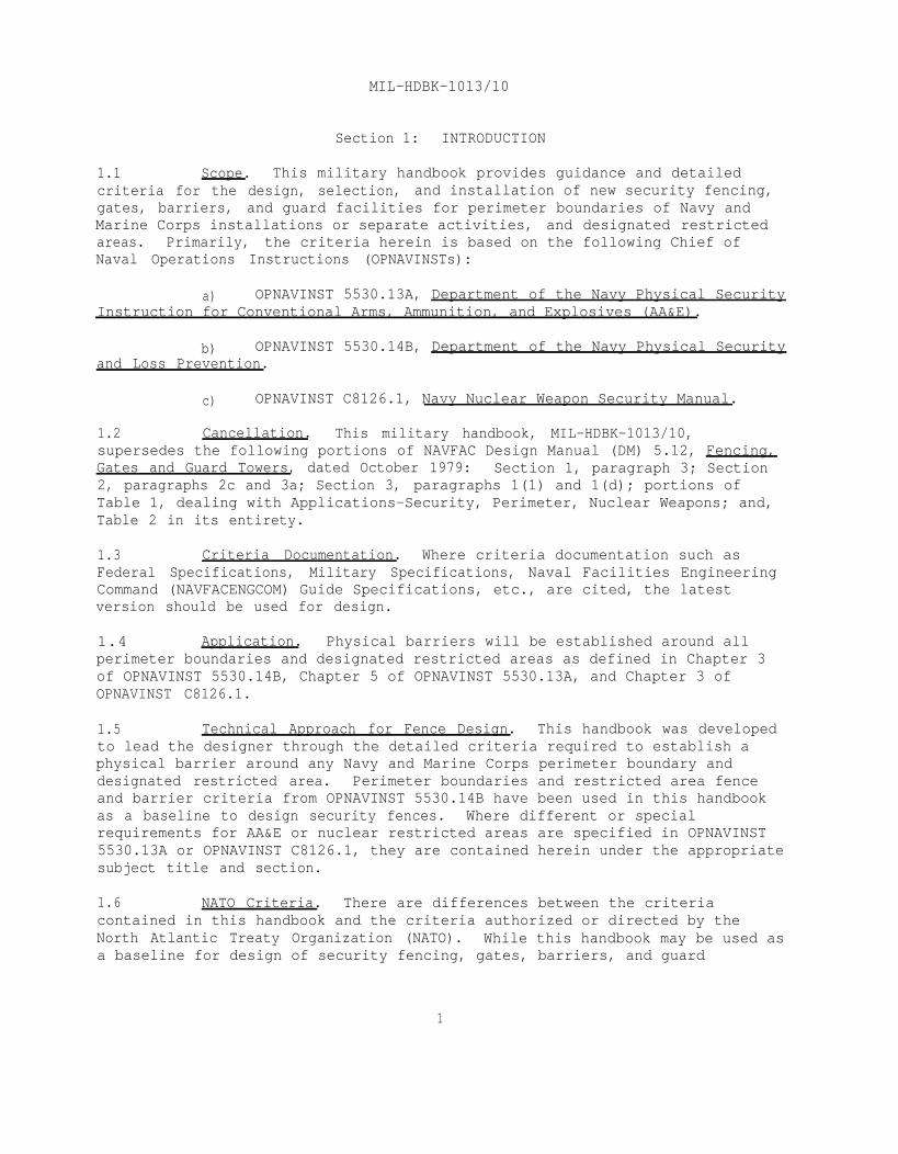
As an alternative, drainage structures may be constructed ofmultiple pipes, each pipe having a diameter of 10 inches (254 mm) or less,joined to each other and to the drainage crossing. An economical solution tosecure metal drainage structures is to weld short (approximately 6-inch(152.4-mm) long) multiple pipes, with diameters less than 10 inches (254 mm),in the "in-flow" end of the drainage culvert as shown in Figure 5.
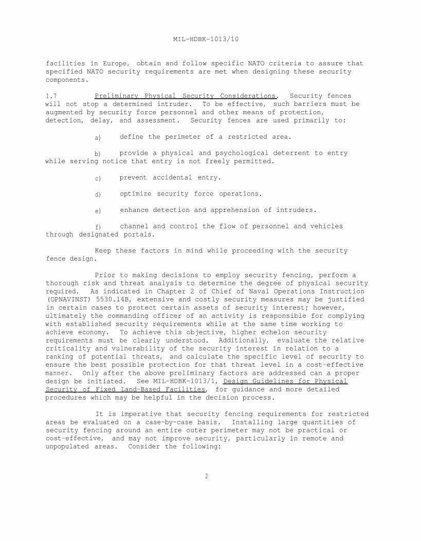
2.3.6.5 Drainage Crossings. Where security fences must cross drainageditches or swales, the designer must assure that the intruders are preventedfrom passing under the fence. Where water flow is minor and generally not aproblem, the main fence may be carried across a ditch or swale with additionalfence added below. The fence added below must be attached every 2 inches(50.8 mm) along the intersection of the two fence sections and either attachedto a series of ground stakes secured to the sides and bottom of the ditch, orembedded in a concrete sill in the ditch or swale (see Figures 6 and 7).
Where heavier flows of water are anticipated, a cross-hatchedscreen type arrangement must be provided below the fence using vertical andhorizontal bars similar to those described in the above paragraph. The flowcapacity must first be analyzed to determine the size grillwork that willaccommodate the maximum amount of water that may be experienced. Rainyseasons and possible debris that can be carried by the flow must be taken intoconsideration. In any case, not more than 9 inches (228.6 mm) will be allowedbetween either vertical or horizontal bars, and bars will be welded at eachintersection (Figure 8).
14
MIL-HDBK-1013/10
Figure 5.Large Culvert with Short Honeycomb Pipes.
Figure 6.Swale Crossing with Ground Stakes.
15

MIL-HDBK-1013/10
Figure 7.Swale Crossing Embedded in Concrete.
Figure 8.Bar Grill Embedded in Concrete.
16
MIL-HDBK-1013/10
MIL-HDBK-1005/3, Drainage Systems, provides considerableinformation concerning design criteria and planning guidelines for drainagesystems. While this guidance should be utilized to design drainage for therestricted area, the designer must assure the security aspects of the designtake precedence over the drainage guidance contained in the MIL-HDBK.
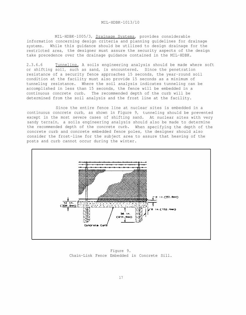
2.3.6.6 Tunneling. A soils engineering analysis should be made where softor shifting soil, such as sand, is encountered. Since the penetrationresistance of a security fence approaches 15 seconds, the year-round soilcondition at the facility must also provide 15 seconds as a minimum oftunneling resistance. Where the soil analysis indicates tunneling can beaccomplished in less than 15 seconds, the fence will be embedded in acontinuous concrete curb. The recommended depth of the curb will bedetermined from the soil analysis and the frost line at the facility.
Since the entire fence line at nuclear sites is embedded in acontinuous concrete curb, as shown in Figure 9, tunneling should be preventedexcept in the most severe cases of shifting sand. At nuclear sites with verysandy terrain, a soils engineering analysis should also be made to determinethe recommended depth of the concrete curb. When specifying the depth of theconcrete curb and concrete embedded fence poles, the designer should alsoconsider the frost-line for the subject area to assure that heaving of theposts and curb cannot occur during the winter.
Figure 9.Chain-Link Fence Embedded in Concrete Sill.
17

MIL-HDBK-1013/10
2.3.7 Maintenance Considerations. Consider the following when designingchain-link fencing:
a) Fence components may require additional protective coatingsin salt-laden and highly corrosive areas, e.g., plastic coating overgalvanized steel fabric.
b) Rapid growth of vegetation in fertile areas and rainyclimates may justify paving the area under the fence and a portion or all ofthe clear zones.
c) Consideration should be given for equipment, i.e., mowers,tractors, etc., required to maintain vegetation below 8 inches (203.2 mm) andto broadcast defoliants or sterilants.
2.3.8 Erosion Control. For erosion control, refer to MIL-HDBK-1005/3,Drainage Systems and NAVFAC DM-5.14, Groundwater Pollution Control. Whereerosion control measures advised in either MIL-HDBK-1005/3 or DM-5.14 violatethe security requirements contained herein, the security requirements takeprecedence.
2.3.9 Grounding. Generally, grounding is not required for chain-linkfences mounted on metal posts. However, fences shall be grounded on each sideof every gate, at points 150 feet (45.7 m) on each side of high-tension linecrossings, and at 150-foot (45.7-m) intervals along the fence where high-tension lines (as defined by ANSI C2) are directly overhead and run parallelto the fence. Fences shall be grounded every 1,000 feet to 1,500 feet(304.8 m to 457.2 m) of length when fences are in isolated places and atlesser distances depending upon proximity of fence to public roads, highways,and buildings. Grounding will also be provided for fenced conventional AA&Eand nuclear weapons storage areas. The ground shall be made with a boltedconnection at a fence post by the use of No. 2/0 AWG (67.4 sq mm) coppercable. Where plastic coated fabric is used, the post shall be bolted, andeach strand of the fence shall be brazed to the metallic bare conductor. Theconductor shall then be grounded. For additional information, see MIL-HDBK-1004/6, Lightning Protection.
2.4 Special Requirements for Fences Equipped with Intrusion DetectionSystems (IDS) Sensors. IDS sensors are often placed on security fences andclear zones to detect aggressors attempting to gain access to an asset.Exterior sensors consist of four major types of field sensors: beam sensors,fence disturbance sensors, seismic sensors, and video motion detectors. Ifexterior IDS sensors are to be included in the fabrication and installation ofsecurity fences, the criteria presented in DM-13.02, Commercial IntrusionDetection System (IDS) should be used.
2.4.1 Taut-Wire Fences. Taut-wire sensored fences may be installedaround designated restricted areas, except for AA&E and nuclear restricted
18

MIL-HDBK-1013/10
areas, when IDS sensors are desired to increase the detection capability ofthe security force.
Taut-wire sensored fences will be 7 feet (2.1 m) high and have a31-inch (787.4-mm) double outrigger equipped with sensor devices. The sensorsystem shall consist of horizontal barbed wire spaced approximately 4 inches(101.6 mm) apart and connected to a central detection device tensioned betweentwo anchor devices. Before designing taut-wire sensored fences, NavalElectronic Systems Engineering Center (NAVELEXCEN) should be contacted for thelatest installation specifications.
2.4.2 Special Requirements. In order to maintain optimal performancefor electromechanical fence sensors, it is imperative that the chain-linkfence be well constructed with tight tensioning maintained throughout thefence line. The fence construction must be adequate to support the addedweight of the IDS. This type of sensor requires frequent fence maintenance.
For additional details and information concerning fence designrequirements for specific fence IDS systems, contact NAVELEXCEN, Code 33, atDSN 563-2030, commercial 803-745-4600 or write:
Naval Electronic Systems Engineering CenterCode 33
4600 Mariott DriveCharleston, SC 29418-6504
2.4.3 IDS Funding. MILCON funds cannot be used for design orconstruction of IDS. MILCON projects may include fence IDS systems funded bythe customer.
2.5 Penetration-Resistant Barriers. Recent terrorist incidentsinvolving the use of suicide-type crash entry forces the consideration ofvehicle barriers capable of stopping large vehicles traveling at high speed.
Crash tests of chain-link fences, similar to the chain-link fencerequired by this handbook, allowed full penetration with no personnel injuriesof both a 1-1/2-ton (1360.7-kg) and 2-ton (1814.4-kg) vehicle traveling at 50miles per hour (80.5 km per hour). An analysis of crash test data indicatesthat, unless enhanced by the addition of cables, fences offer littleprotection against penetration. Consequently, to meet a vehicle threat, fencereinforcement measures may be required to maintain security of a restrictedarea. Crash tests performed on a chain-link fence reinforced with a 3/4-inch(19.1-mm) aircraft cable restricted penetration of a 2-ton (1814.4-kg) vehicletraveling at 50 mph (80.5 km/h) to 26 feet (7.9 m).
When selecting barriers for penetration resistance, the designershould choose active or passive barriers based on their capacity to stop thethreat vehicle at the maximum speed it could attain in its approach.
19

MIL-HDBK-1013/10
a) Passive Barriers. Use passive barriers where unmovablebarriers are needed, such as along a perimeter chain-link fence.
b) Active Barriers. Use active barriers where vehicles must beallowed passage, but the capacity to stop them must also be maintained.
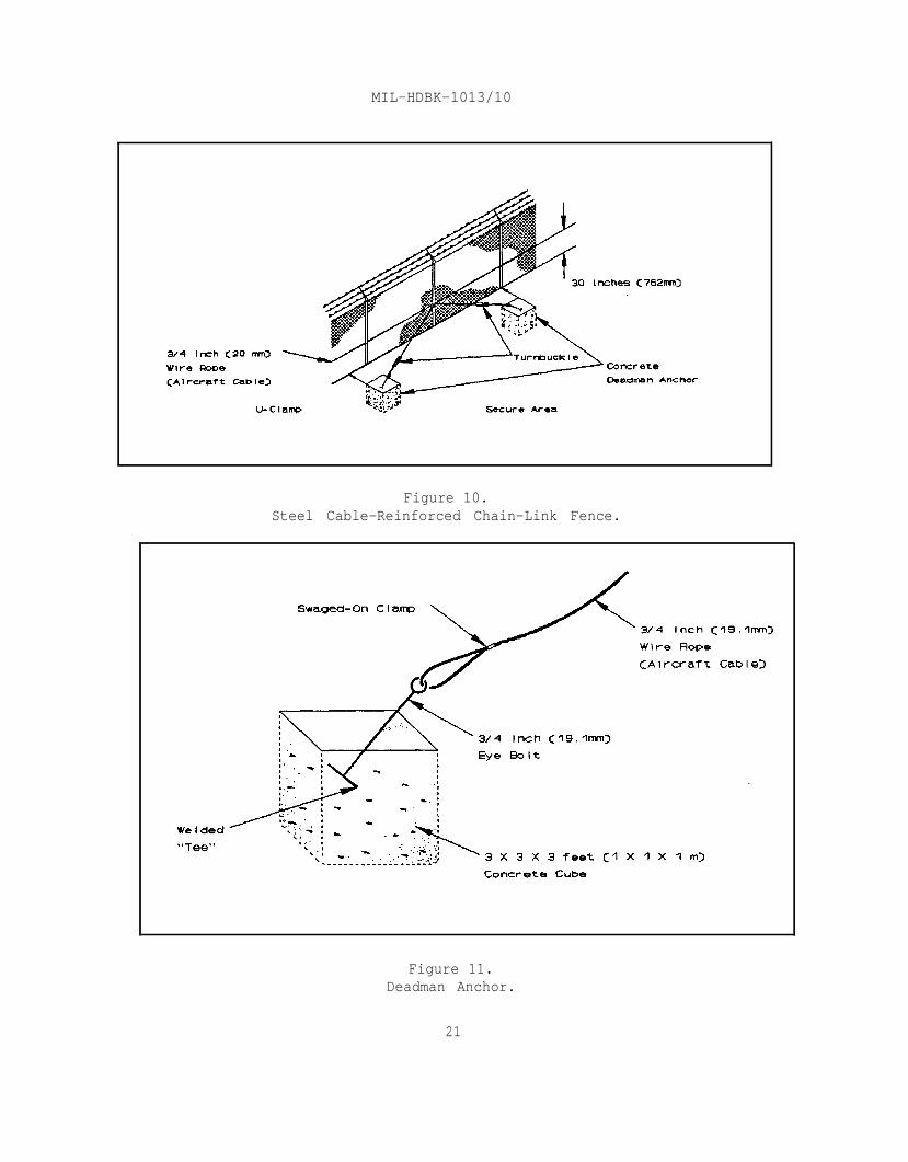
2.5.1 Reinforcement of Perimeter Chain-Link Fence. A reasonableapproach to reinforce a standard chain-link perimeter fence to resist avehicle attack is both simple and aesthetic. Place a 3/4-inch (19.1-mm)diameter aircraft cable, conforming to MIL-W-83420, along the fence line,between the fence posts and the chain-link fabric as shown in Figure 10.Fasten the cable with 1/2-inch (12.7-mm) U-clamps (SAE Grade 3 or better) at aheight of approximately 30 inches (762 mm) from ground level. Terminate eachcable end with either three wire rope clamps (MS16842) or a wire ropehydraulically swaged press fitting (MIL-P-80104). The cable end will beattached to one end of a 3/4-inch (19.1-mm) round turnbuckle (MS51561) withdouble eye ends which in turn will be attached to the deadman eyebolt (MIL-B-45908) by a 3/4-inch (19.1-mm) anchor shackle (SAE Grade 8 or ASTM A 490).
The deadman anchor will be a concrete cube, approximately 3 by 3by 3 feet (1 by 1 by 1 m). Eyebolts captured in the deadman anchors will haveeither a welded "T" or "L" end embedded in the concrete as shown in Figure 11.As a minimum, 2 feet (0.610 mm) of the eyebolt and its welded extension willbe captured within the concrete of the deadman. The shaft of the eyebolt willbe either in-line with the attached cable or the eye of the eyebolt will beflush with the surface of the deadman. Anchors shall be placed at a minimumof 200-foot (60.9-m) intervals and a maximum of 1,000-foot (304.8-m) intervalson the inside of the perimeter fence with the front edge of the deadman flushwith the fence fabric. The top of the deadman will be either flush or buriedbelow the surface as long as the eye of the eyebolt is above ground level.Cables must overlap as shown in Figure 10 before terminating at a deadman sothat no voids in the cable occur along the perimeter. If additional hardeningis desired, a second cable should be placed about 5 inches (127 mm) above thefirst cable and attached as described above. It may be anchored to the samedeadmen used by the first cable system.
When gates form a portion of the fence line being protected by avehicle restraint cable system, then the gate cable system described inSection 3 must be interconnected to the fence cable system to ensurecontinuity of the cable system. Often, natural barriers such as mountains,cliffs, rivers, seas, trees, vegetation, or other terrain protect the fencefrom vehicle attack. The vehicle restraint cable system should not be usedalong portions of the fence line that are otherwise protected by naturalbarriers, such as large boulders, trees, natural ravines, and ditches.
20
MIL-HDBK-1013/10
Figure 10.Steel Cable-Reinforced Chain-Link Fence.
Figure 11.Deadman Anchor.
21

MIL-HDBK-1013/10
2.5.2 Additional Barriers. Alternatives to the barriers listed above,along with a decision tree for vehicle barrier selection and design criteria,can be found in the NCEL Terrorist Vehicle Bomb Survivability Manual, July1988. Many of the passive barriers contained in the manual may be moreconvenient, suitable, or economical to install than the fence cable vehiclerestraint system. The fence location should drive the actual selection of abarrier or barrier system. Some examples of active and passive vehiclebarriers are:
a)
b)
c)
d)
e)median barriers.
f)
g)
h)
i)
Active (pop-up) type vehicle barriers.
Both active ("pop-up") and passive bollards.
Across-the-road bar-type barriers.
Dragnet systems.
Concrete planter boxes, jersey bounces, anchored concrete
Buried heavy equipment tires.
Concrete and concrete block walls.
Sand filled 55-gallon (208.2-liter) drums.
Highway-type guard rails and cable systems.
22

MIL-HDBK-1013/10
Section 3: GATES
3.1 Application. Gates facilitate control of authorized traffic andits flow. They establish specific points of entrance and exit to an areadefined by fences. They also function to limit or prohibit free flow ofpedestrian or vehicular traffic, while establishing a traffic pattern forrestricted areas.
3.2 Related Criteria. Gates, as a part of perimeter fences, must beas effective as their associated fence to provide an equivalent deterrent.Gates will normally require additional hardening features due to theirlocation across entrance roads and the inherent vulnerability of their hingesand latches. Gates are known to be the weakest point in the perimetersecurity fence and as such, you must pay attention to their requirements whendesigning security fencing.
Materials used in fabricating and erecting chain-link gates mustbe the same as the materials used for the associated chain-link fence. As forsecurity fences, aluminum pipe, poles, fabric, or accessories will not be usedor specified for security gate components. Use American Society for Testingand Materials (ASTM) standards to supplement Federal specifications whenfurther detail or criteria is desired.
3.3 Types of Gates. Federal Specification RR-F-191/2 is the basiccriteria document for security fence gate design. It provides specificationsfor the following eight types of chain-link fence gates:
a) Type I - Single Swing Gates.
b) Type II - Double Swing Gates.
Gates.c) Type III - Single Cantilever Sliding Gates, Wheel Sliding
d) Type IV - Double Cantilever Sliding Gates.
e) Type V - Single Overhead Sliding Gates.
f) Type VI - Double Overhead Sliding Gates.
g) Type VII - Vertical Lift Gates.
h) Type VIII - Special Gates.
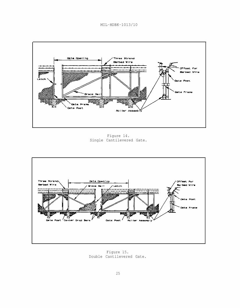
The gate types listed above are the most common gateconfigurations used for security fencing. These include single and doubleswing gates (Figures 12 and 13), single and double cantilevered gates (Figures14 and 15), wheel-supported (V-groove) sliding gates (Figure 16), and single
23

MIL-HDBK-1013/10
and double (biparting) overhead supported gates (Figures 17 and 18). Whileany of these may be used for pedestrian or vehicular traffic, generally singlegates will be designed for pedestrian traffic and double gates for vehiculartraffic.
Figure 12.Single Swing Gate.
Figure 13.Double Swing Gate.
24
MIL-HDBK-1013/10
Figure 14.Single Cantilevered Gate.
Figure 15.Double Cantilevered Gate.
25

MIL-HDBK-1013/10
Figure 16.Single Wheel-Supported (V-groove) Sliding Gate.
Figure 17.Single Overhead Supported Gate.
26

MIL-HDBK-1013/10
Figure 18.Double Overhead Supported (Biparting) Gate.
The vertical lift gate (not shown), often referred to as a"guillotine" gate, is not desirable and should only be used under extremelyunusual circumstances. Special gates, such as turnstile (rotational) gates(Figure 19), are designed either for specific purposes or to accommodateunusual circumstances.
Figure 19.Turnstile (Rotational) Gate.
27
MIL-HDBK-1013/10
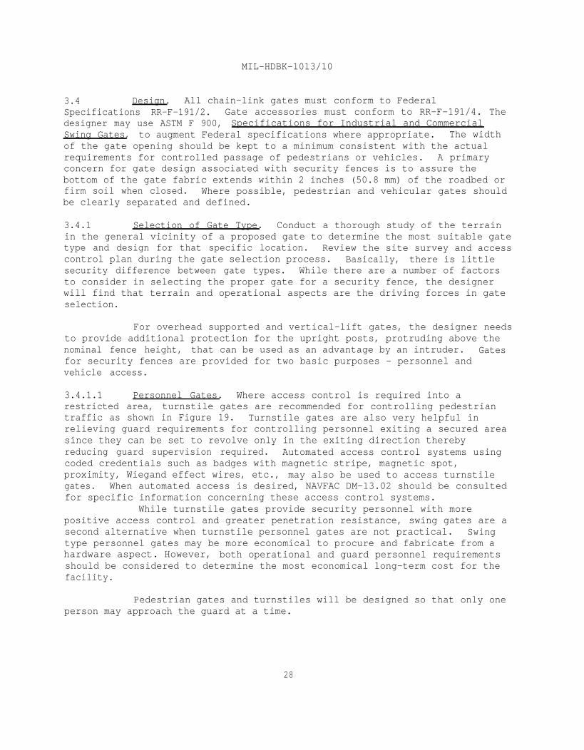
3.4 Design. All chain-link gates must conform to FederalSpecifications RR-F-191/2. Gate accessories must conform to RR-F-191/4. Thedesigner may use ASTM F 900, Specifications for Industrial and CommercialSwing Gates, to augment Federal specifications where appropriate. The widthof the gate opening should be kept to a minimum consistent with the actualrequirements for controlled passage of pedestrians or vehicles. A primaryconcern for gate design associated with security fences is to assure thebottom of the gate fabric extends within 2 inches (50.8 mm) of the roadbed orfirm soil when closed. Where possible, pedestrian and vehicular gates shouldbe clearly separated and defined.
3.4.1 Selection of Gate Type. Conduct a thorough study of the terrainin the general vicinity of a proposed gate to determine the most suitable gatetype and design for that specific location. Review the site survey and accesscontrol plan during the gate selection process. Basically, there is littlesecurity difference between gate types. While there are a number of factorsto consider in selecting the proper gate for a security fence, the designerwill find that terrain and operational aspects are the driving forces in gateselection.
For overhead supported and vertical-lift gates, the designer needsto provide additional protection for the upright posts, protruding above thenominal fence height, that can be used as an advantage by an intruder. Gatesfor security fences are provided for two basic purposes - personnel andvehicle access.
3.4.1.1 Personnel Gates. Where access control is required into arestricted area, turnstile gates are recommended for controlling pedestriantraffic as shown in Figure 19. Turnstile gates are also very helpful inrelieving guard requirements for controlling personnel exiting a secured areasince they can be set to revolve only in the exiting direction therebyreducing guard supervision required. Automated access control systems usingcoded credentials such as badges with magnetic stripe, magnetic spot,proximity, Wiegand effect wires, etc., may also be used to access turnstilegates. When automated access is desired, NAVFAC DM-13.02 should be consultedfor specific information concerning these access control systems.
While turnstile gates provide security personnel with morepositive access control and greater penetration resistance, swing gates are asecond alternative when turnstile personnel gates are not practical. Swingtype personnel gates may be more economical to procure and fabricate from ahardware aspect. However, both operational and guard personnel requirementsshould be considered to determine the most economical long-term cost for thefacility.
Pedestrian gates and turnstiles will be designed so that only oneperson may approach the guard at a time.
28

MIL-HDBK-1013/10
For nuclear storage areas, the personnel entry gate complex, toinclude access and exit routes, will be designed in accordance with NAVFAC P-272, Definitive Drawings, drawing number 1404126.
3.4.1.2 Vehicle Gates. Either wheel-supported or cantilever sliding gatesare the best selection for vehicle security gates followed by overhead slidinggates. Swing gates are a third alternative and lastly, by far the leastdesirable, are overhead ("guillotine") gates. Initially, the designer shouldbegin by evaluating the wheel-supported or cantilever sliding gate. Aninitial step in the design is to determine the operational requirements forthe gate. Determine the daily peak and normal work flow of vehicles.Ascertain the operational access control requirements for the secured area,i.e., badging, penetrator threat, magnetic sensor personnel monitoring,package surveillance, type (size) of vehicles to use the gate, etc. Thesedetails will lead to determining the type and size of gates, desirability orrequirement for automatic openers, special hardening requirements, etc. Inareas known for snow or ice buildup, internal heating should be considered inthe gate design.
3.4.1.2.1 Sliding Gates. Sliding gates, when open, store parallel to theadjacent fence line, unlike the large sweeping arc that swing gates require.When designing the roadbed at the gate opening, the surface should be kept asstraight as possible, allowing for drainage by a slight incline to one side orthe other of the entire roadbed. When an existing road surface is encounteredthat is not essentially flat, the designer should require asphalt or concretefill to level the roadbed where the gate will be installed.
The cantilever gate design, (Figures 14 and 15), provides fullsupport and suspension of the gate frame by four rollers secured to two postsinside the restricted area. Since the required length of a cantilever gate is1-1/2 times the size of the opening, there must be a straight, and essentiallylevel, fence line adjacent to the gate to accommodate this length when thegate is fully open. Cantilever gates can compensate for a somewhat crowned orunlevel roadbed and do not require a "V"-bar guide rail or trough across theroadbed. Cantilever sliding gates are not recommended for openings exceeding24 feet (7.3 m), although two biparting sliding cantilever gates can be usedfor openings up to 48 feet (14.6 m).
Wheel-supported gates (Figure 16) for security fences requireeither a guide rail ("V"-groove) or trough across the roadbed. With the "V"-groove design, the gate's leading edge utilizes a wheel that has a deep groovecut into its outside circumference. This wheel travels on inverted angle ironthat is secured across the roadbed on the ground. The rear of the gatetravels with two wheels riding in "C" channels as shown in Figure 16. Thetrough design utilizes a metal wheel with a convex diameter that rides down ina groove extending across the roadbed. While the trough provides a smoothersurface for vehicular traffic, it is not recommended due to typical debrisbuildup in the groove causing the wheel to ride up out of the groove onto theroadbed surface. In both styles, the upper portion of the gate is supported
29

MIL-HDBK-1013/10
laterally by additional vertical rollers. Since wheel-supported gates are notcantilevered, they only need to be somewhat longer than the actual size of thegate opening, requiring one-third less straight and level storage length alongthe fence line than the cantilever gate. Wheel-supported gates essentiallyare not limited in the size of their opening except for the power requirementsof the gate operator. A variation of the wheel-supported gate is one usingdual pneumatic, hard rubber, or steel wheels to support the gate. These canbe identified by their lack of roadbed guides. They should only be used as alast resort, and then only for manually opened sliding gates.
3.4.1.2.2 Overhead Gates. Overhead gate design requires either an I-beam oran enclosed track (Figures 17 and 18), suspended over the width of the openingand extending an equidistance on one side or the other of the gate opening tostore the gate when it is opened. Similar to wheel-supported and cantilevergates, the gate must store parallel to the adjacent fence line. The gatestorage area must be in line with the gate opening and either be level or havea decreasing grade to accommodate the gate when it is fully open. The gate issuspended from the I-beam or enclosed track by a pair of rollers attached toposts extending upward from the leading and trailing edge of the gate. Theoverhead beam or track height must allow clearance for anticipated truck orrail traffic. The gate will be suspended above the ground from the overheadbeam or track and supported laterally near the ground by vertical rollers.The enclosed track design incorporates the best of the overhead gate designs,and is well suited for automatic operators. The tracking system provides theconvenience of a wheel-supported or cantilever-type installation, but with amuch more efficient means to roll the gate. The amount of force to operategates with these designs is significantly less than that of comparable gates.High-cycle demands, large opening sizes, or heavy gate construction mayrequire strengthening the overhead I-beam design. Additional upright postsextending upward from the center of the gate will also allow the enclosedtrack to carry heavier loads.
3.4.1.2.3 Swing Gates. Swing gates (Figures 12 and 13) should be designedso that they swing inward, toward the secured area. The disadvantage of theswing gate is the large arc of space required for operation. Swing gates caneither be designed to swing 90 degrees inward and 90 degrees outward or swing180 degrees inward only. An important consideration in selecting a single ordouble swing gate design is maintaining clearance along the bottom of the gateas it swings through its arc from the closed to the open position. If thegrade is increasing inside of the gate, grading will be required to allowclearance. The required 2-inch (50.8-mm) maximum clearance between the bottomof the fence and the roadbed must be maintained when the gate is in the closedposition.
The swing gate design places considerable weight on the hinge post andits foundation. The longer the gate, the more load (moment arm) placed on thegate post. ASTM F 900 provides design detail for single swing gates up to 24feet (7.3 m). Ideally, single swing gates should not exceed 14 feet (4.3 m)and double swing gates should not exceed 28 feet (8.5 m). Since the weight of
30

MIL-HDBK-1013/10
the gate must be borne by the gate post, design of the gate post and itsfoundation is critical to assure proper support of the swing gate. Anundersized or improperly installed gate post may shift and cause the gate tomove out of plumb with the ground. This may cause the gate to drag on theground or change elevation as the gate moves through its arc from the openedto closed position. Table 1 provides recommended concrete foundationdiameters for swing gate posts. As a minimum for swing gate posts, theconcrete foundation should be 3 feet (1 m) deep.
Table 1.Gate Post Foundations.
STEEL POST DIAMETER FOUNDATION HOLE DIAMETER GATE LEAF LENGTH
2.875 in (73 mm) 18 in (450 mm) 0 - 6 ft (0 - 1.8 m)
4.000 in (101.6 mm) 24 in (609.6 mm) 6 - 12 ft (1.8 - 3.7 m)
6.625 in (168.3 mm) 36 in (914.4 mm) 12 - 18 ft (3.7 - 5.5 m)
8.625 in (219 mm) 40 in (1016 mm) 18 - 24 ft (5.5 - 7.3 m)
3.4.1.2.4 Vertical Lift Gates. Vertical lift ("guillotine") gates shouldonly be used when the gate location is mandated, the site is so restricted, orthe weather is so severe, that a gate must be placed in such a location wherethe only way to open it is upward. Vertical lift gates should never beconsidered except as a last possible design choice. When a vertical lift gateis required, a counterweight with a continuous drive chain on each side (thatpulls the gate both up and down) must be specified.
3.4.2 Hinges. The weight, size, and frequency of use are importantfactors in the selection of gate hinges. Specific design guidance is notcontained in the military specification or associated ASTMs. Gate hinges musthave adequate strength to support the gate and have large bearing surfaces forclamping them into position. Commercial hinges manufactured to fit increasingdiameters of gate posts also have increased mass and capability to supportlarger swing gates and generally will be found acceptable. The hinges must besecured to the gate post and the gate frame to assure they will not twist orturn under the weight and action of the gate. Welding is recommended. Gatehardware must conform to RR-F-191/2. ASTM F 900 may be used to supplement themilitary specification. Hinges must be tamper-proof by the addition of weldedsecurity plates or by reversing the direction of the hinge pins (one up, theother down), thereby protecting the gate from being lifted off. Bolts andother hardware associated with gate hinges must be welded or peened to preventtheir removal by hand tools.
3.4.3 Locking System. Gates will be provided with locking hardwareconforming to RR-F-191/2. The locking system is designed to provide an equallevel of penetration resistance when a gate is closed and locked with an
31

MIL-HDBK-1013/10
approved General Field Service Padlock. Where locking hardware is notpracticable, 1/2-inch (12.7-mm) chains meeting the requirements of RR-C-271(Table 2, Type 1, Grade C, Class 1), will be used with an approved GeneralField Service Padlock.
While automatic latching (locking) devices are required forvehicular and personnel gates at nuclear storage facilities, they also shouldbe considered during any security gate design.
At nuclear weapons storage sites, vehicle entry sally-port(s),personnel swing gates, and turnstiles, each with their associated gatelatching systems, will be designed in accordance with NAVFAC P-272, DefinitiveDrawings drawing number 1404126. These drawings specify vehicle sally-portsthat consist of an enclosed area with two vehicle gates. The gates areelectrically controlled so when a vehicle enters, the inner gate is closedwhile the outer gate is open. The outer gate must be closed and latchedbefore the inner gate can be opened to allow the vehicle to enter therestricted area. The design accommodates the reverse procedure for vehiclesexiting the restricted area. All pedestrian and vehicle gates incorporate anautomatic electrical latching feature when closed. The remotely controlledgates are operated from the Entry Control Point (ECP). An emergency overrideis provided in the ECP to allow both gates to be opened simultaneously foremergency vehicles.
Many power operators for sliding gates are designed to "lock-up"gate motion by means of an internal friction brake system that engages whenthe operator is stopped. This type of locking device is not adequate tosecure the gate when it is not manned by security personnel; therefore, one ofthe locking or latching methods discussed above must be provided.
3.4.4 Gate Power-Operators. As noted above, gate power-operators withautomatic latching (locking) systems are required for vehicular gates atnuclear storage facilities. With the requirements of access control becomingmore sophisticated and involved, the use of power-operators for gates at othertypes of restricted areas is more compelling for active vehicular securitygate operation. The designer should analyze the facility access controlprocedures and anticipated traffic flow through each proposed vehicular gate.From this analysis, the potential effectiveness of a power-operator inimproving access control operations for gates can be evaluated. When verticallift gates are designed, gate power-operators are mandatory except in rarecircumstances when the gate will seldom be used and manual operation of thegate is reasonable.
Gate power-operator controls must be located so they cannot bereached or tampered with from outside the security fence. Most gates willrequire site-peculiar operating accessories, warning devices, or safetysystems in addition to the actual operator. The designer should coordinatethe design of gate power-operators with the command safety officer.
32

MIL-HDBK-1013/10
3.4.4.1 Gate Power-Operator Design. A manufacturer's design (usingsimilar components), the standard features provided, and optional accessoriesavailable are what primarily separates one manufacturer's products fromanother. Some manufacturers provide a full line of power-operators for gatesin all horsepowers, voltages, and phases, while others limit selection to oneor two models which may provide inadequate horsepower and improper voltagesfor the gate being designed. Gate power-operator capabilities are ofparticular concern when cantilever gates are installed, particularly when thegrade increases from side to side of the opening.
3.4.4.1.1 Sliding Gate Power-Operators. Power-operators for sliding gatescan generally be associated in three groups based upon their method ofoperation. These are:
a) Electromechanical Chain Driven - An electric motor drives aseries of reduction and worm gears, chains, and sprockets which in turn drivea chain attached to the gate thereby operating the gate.
b) Electromechanical Rack and Pinion - An electric motor,through gear reduction, operates a rack and pinion gear arrangement attachedto the gate thereby operating the gate.
c) Hydraulic Compression Rail - An electric motor operates ahydraulic pump which in turn drives two hydraulic motors. The drive wheelmounted on each motor is compressed and runs on opposing sides of a rail (legof angle iron), with the other angle iron leg attached to the gate to operatethe gate.
The hydraulic compression rail gate power-operator is preferredfor automating sliding gates at restricted areas. An independent life-cyclecost analysis, conducted by NCEL, indicates that hydraulic compression railgate power-operators for horizontal sliding gates offer reasonable acquisitioncost, low operations and support costs, and the lowest risk to the Government.
3.4.4.1.2 Swing Gate Power-Operators. Power-operators for swing gates cangenerally be placed in two groups based upon their method of operation. Theseare:
a) Hydraulic Piston - A hydraulic piston is attached betweenthe gate leaf and an offset post. The piston is extended and contracted tooperate the gate.
b) Electromechanical Swing Arm - An electric motor, throughgear reduction, operates a primary arm that travels in an arc parallel to theground. A second arm is attached between the gate leaf and the primary armthereby operating the gate.
While an independent life-cycle cost analysis for swing gatepower-operators has not been made, preliminary analysis indicates that the
33

MIL-HDBK-1013/10
hydraulic piston type of swing gate power-operator has a greater degree ofreliability, particularly in areas of measurable snowfall. Greaterreliability generally relates to lower maintenance cost. With the acquisitioncost of swing gate power-operators being comparable, the hydraulic piston typeof swing gate power-operator is recommended for swing-gates.
3.4.4.1.3 Gate Power-Operator Peripherals. The means of activating gatepower-operators can be as simple as push buttons to open, close, and stop thegate or can be a very complex electronic automated system. The requirementsof controlling the motion, direction, braking, and locking of the gate andgate power-operator are increasingly more demanding. Manufacturers canprovide many additional features as standard equipment such as "pause toreverse" and "maximum run time." ("Pause to reverse" delays the gate fromimmediately reversing from an open cycle to a close cycle, thereby avoidingthe shock load on the gate power-operator's mechanics; "Maximum run time"prevents the gate power-operator from continuing to run after a preset time ifthe gate is obstructed.)
Access control must be a primary consideration for the designerwhen designing gate systems. Access control may be as simple as having aguard physically open a gate to allow access, or as complex as a system thatlogs the activity of individuals and the time of their access to specifiedareas by use of a designated code number. Features, devices, and electronicequipment to automate or expedite access control should be considered duringthe design of power-operated gates.
A number of issues must be addressed before an access controlsystem design can be considered complete. These include pedestrian traffic,reversing devices to keep gates from closing on vehicles, traffic flow, numberof open and close cycles, and type of vehicular traffic. The designer needsto analyze the operational site security plan and review the details of hison-site inspection. Next, he should discuss access requirements for therestricted area(s) concerned with the facility Security Officer to determinethe degree of access control required. Electronic access control has a verybroad spectrum of devices, technology, and capabilities. DM-13.02 should beconsulted for specific information concerning electronic access controlsystems. Additionally, technical guidance may be obtained from the NavalElectronic Systems Engineering Center (NAVELEXCEN), Code 33 at DSN 563-2030(803-745-4942) or write:
Naval Electronic Systems Engineering CenterCode 33
4600 Mariott DriveCharleston, SC 29418-6504
The following are several considerations for selecting peripheral equipment toactivate gate power-operators:
34

MIL-HDBK-1013/10
a) Who will be authorized to activate the operators and whereare they located? (Guard in Access Control Point, remote radio control, keyswitch, push button, card reader?)
b) How will access control personnel communicate with personneldesiring entrance and exit from the restricted area? (Directly, intercom,telephone?)
c) How will the gate be closed after the vehicle has gainedentry? (Guard personnel, automatic timer, infrared (IR) beam?)
d) How will the gate be opened and closed to permit vehicleexit? (Guard personnel, IR beam, button or keypad, remote radio control,roll-across sensor, card reader?)
3.5 Number and Location of Gates. Gates will be limited to the veryminimum number to support efficient operations. Centers of activity, facilityoperations, personnel concentrations, as well as vehicular traffic flow insideand outside the restricted area must be analyzed before locating gates.Alternative gates, which are closed except during peak movement hours, may beprovided so that heavy traffic flow can be expedited. Whenever possible,alternate gates should be located so that they are under observation of thenormal guard force. All gates will be locked to form an integral part of thefence when closed.
3.6 Traffic Control. Traffic control at restricted areas during peakhours must be evaluated for both pedestrian and vehicular access whendesigning the entry control complex. Vehicular gates for restricted areasmust be set back from any public or military roadway to ensure that temporarydelays caused by identification checks will not cause traffic hazards.Sufficient space should also be provided to allow for spot checks,inspections, and searches of vehicles without impeding the flow of traffic.
Entry control design must afford maximum security while minimizingdelay in the flow of authorized traffic. Figure 20 provides a characteristicentry control arrangement for a restricted area that has a high volume ofassigned personnel and visitors to access daily. Inbound visitors andunauthorized vehicles are diverted from the normal flow entering therestricted area. They have the opportunity to either voluntarily reversetheir direction and not approach the ECP, or obtain appropriate vehicle andpersonnel passes to proceed into the restricted area. A second turnaround isprovided immediately beyond the ECP, but prior to the remotely controlledrestricted area gates, so that security personnel can reverse the direction ofvehicles or personnel that arrive at the ECP without proper passes or decalsprior to accessing the restricted area. As a final security measure, remotelycontrolled active (pop-up) vehicle barriers may be provided inside the gatesto obstruct forced or high-speed entry into the restricted area. Tireshredders or remotely controlled active vehicle barriers may also be provided
35

MIL-HDBK-1013/10
inside the exit gate to slow down or forcibly stop a high-speed entry attackthrough the exit.
Figure 20.Entry Control Point Layout.
The ECP shown in Figure 21 represents an entry control arrangementfor a restricted area securing critical components but having a low volume ofassigned personnel and minimal visitor traffic to access daily. Directstraight-in vehicle access is impeded by a sharp curve and passive vehiclebarriers to lessen the possible success of a high-speed vehicle attack.Personnel must pass through turnstiles on foot, one at a time to access therestricted area. Vehicles are processed and inspected in a sally-port areabefore being allowed to enter or exit the restricted area. Sally-port gatesand personnel turnstiles are paired in-line with the direction of entry sothat one must be closed and locked before the other of the pair may be opened.Gate opening and locking system overrides must be provided for emergencyvehicles. All opening, locking, and emergency controls are contained withinthe ECP building.
36

MIL-HDBK-1013/10
3.7
Figure 21.High Security Site Entry Control Facility.
Penetration-Resistant Barriers. As discussed in Section 2 forfences, consideration of various vehicle barriers and crash deterrents shouldbe made during gate design. When passive and active vehicle barriers areprovided for gates, the fence line must also be hardened along those areassubject to vehicular attack. The designer should refer to the Naval CivilEngineering Laboratory Terrorist Vehicle Bomb Survivability Manual, July 1988,that has been distributed to Engineering Field Divisions and Public WorksCenters. This manual not only has considerable detail on many active andpassive vehicle crash barriers, but provides a vehicle barrier selectiondecision tree to aid the designer in selecting and designing appropriatevehicle crash barriers for restricted area gates and adjoining securityfences.
3.7.1 Reinforcement of Swing Gates. The locking mechanism and thehinges on a security swing gate are the weakest components of the gate system.These areas can be reinforced by combining chain and wire rope (cable) to form
37

MIL-HDBK-1013/10
a barrier across the opening. Once the chain and wire rope has been installedas shown in Figure 22, the energy of a vehicle crash attempt is transferredfrom the gate through wire rope links to the side gate posts, and further tothe fence cable reinforcement system and deadman concrete anchors. The fencereinforcement cable is terminated with a swaged loop around the gate post tointerconnect with the gate cable barrier system. With the wire ropes linkedtogether at the fence posts as shown in Figure 23 and chained together attheir point of closure as shown in Figure 24, in effect there is a continuousbarrier across the opening. The system is simple, unobtrusive, and effective.When the chain is removed, gate leafs can be operated normally withoutrestriction.
Figure 22.Chain and Wire Rope Reinforced Gate.
To construct the gate barrier system, a 3/4-inch (19.1-mm)diameter aircraft wire rope, conforming to MIL-W-83420, is looped around thegate post as shown in Figure 23, around the gate frame upright, and throughthe fence cable loop. The wire rope is strung across the inside of the gateleaf and fastened around the vertical gate frame upright and fabric tensionbar midway above the roadbed as shown in Figure 22. Where gates have twoleafs involved, a cable will be installed in the same manner on the secondleaf. All cable ends are looped and terminated with either three wire ropeclamps (MS16842) as shown in Figure 25 or hydraulically swaged wire ropefittings (MIL-P-80104) as shown in Figure 26.
38

MIL-HDBK-1013/10
Figure 23.Wire Rope Interwoven at Gate Post.
Figure 24.Chain and Wire Rope Locking System.
39

MIL-HDBK-1013/10
Figure 25.Wire Rope Clamps.
Figure 26.Hydraulically Swaged Wire Rope Fitting.
The critical component of the gate reinforcement system is thechain used to fasten the gates together. When the gates are closed, a 1/2-inch (12.7-mm) diameter welded steel alloy chain conforming to RR-C-271 (Table2, Type 1, Grade C, Class 1), is passed through each of the wire rope loops atthe opening and around the two upright gate posts, then snugly fastenedtogether with a Medium Security Padlock (MIL-P-43951) as shown in Figure 24.
There are times when a gate reinforcement cable barrier system isdesired but a cable reinforcement system for the adjoining fence is not
40

MIL-HDBK-1013/10
necessary since terrain, natural barriers, structures, or other passivebarrier features provide vehicle crash protection adjacent to the gate. Insuch cases, the gate cable system can be terminated directly on each side ofthe gate with the deadman concrete anchors described for the vehicle restraintcable system in Section 2.
3.7.2 Reinforcement of Sliding and Vertical Lift Gates. While there isno "generic" or standard solution for hardening the various configurations ofsliding and vertical lift gates that may be designed, the reinforcementmaterials used for swing gates above may be used effectively by the designerto reinforce either sliding or vertical lift gates.
For example, a 3/4-inch (19.1-mm) wire rope (cable) (MIL-W-83420)could be attached along the length of a sliding gate as shown in Figure 27 ora vertical lift gate as shown in Figure 28. The cable ends are then loopedsecurely around the gate frame uprights at each end as shown in Figure 29.The end of the fence reinforcement cable system should be looped around theterminal posts on each side of the gate opening as shown for gate posts forswing gates in Figure 22. A 1/2-inch (12.7-mm) diameter welded steel alloychain conforming to RR-C-271 (Table 2, Type 1, Grade C, Class 1), can then bepassed around the fence terminal post and the gate frame upright, passingthrough both the fence and gate cable loops as shown in Figures 29 and 30.Again, all cable ends are looped and terminated with either three wire ropeclamps (MS16842) as shown in Figure 25 or hydraulically swaged wire ropefittings (MIL-P-80104) as shown in Figure 26. A medium security padlock (MIL-P-43951) is used to snugly fastened the chain together as shown in Figures 29and 30.
41

MIL-HDBK-1013/10
Figure 27.Cable Reinforcement For a Sliding Gate.
Figure 28.Cable Reinforcement of a Vertical Lift Gate.
42

MIL-HDBK-1013/10
Figure 29.Chain and Wire Rope Reinforcing Sliding Gate.
43

MIL-HDBK-1013/10
Figure 29 - Continued.Chain and Wire Rope Reinforcing Sliding Gate.
44
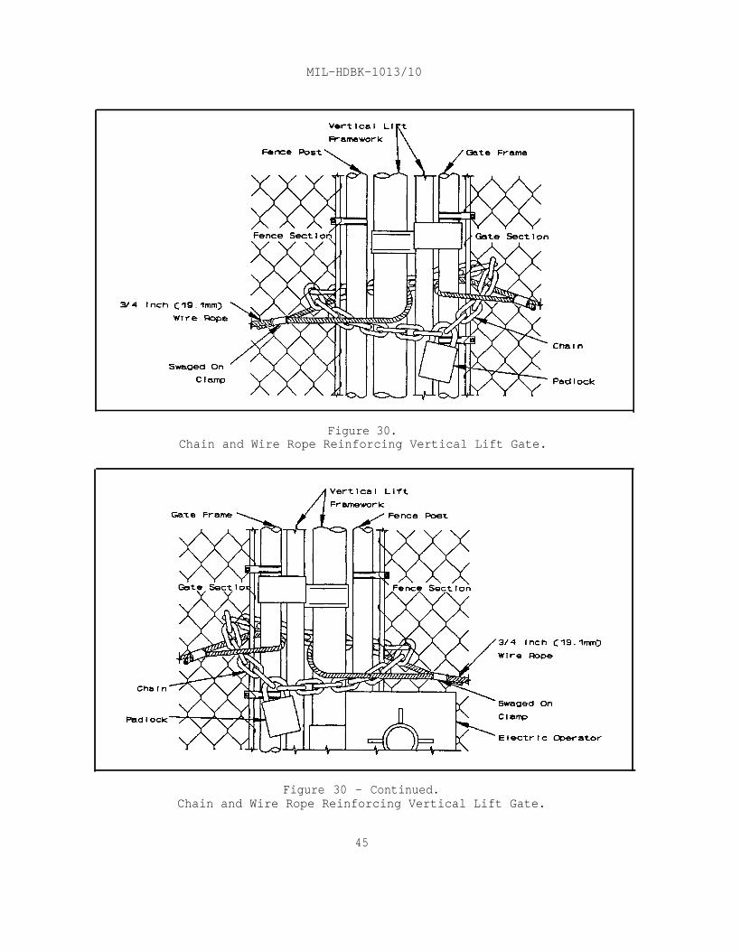
MIL-HDBK-1013/10
Figure 30.Chain and Wire Rope Reinforcing Vertical Lift Gate.
Figure 30 - Continued.Chain and Wire Rope Reinforcing Vertical Lift Gate.
45
MIL-HDBK-1013/10
Section 4: GUARD FACILITIES
4.1 Application. Sentry booths, gatehouses, and guard towers are anintegral part of a perimeter security system. Sentry booths and gatehousesare the points where personnel and vehicle control and badge exchangeoperations are conducted. Guard towers, properly designed and located arounda restricted area, increase the range of observation and enhance the responseof security personnel.
4.2 Related Criteria. MIL-HDBK-1013/1 designates four levels ofsecurity protection for structure design: low, medium, high, and very high.An associated design threat (attack tools or methods) along with thepenetration delay time and ballistic resistance required for design is givenfor each level of protection. The determination of the category of securityrequired against ballistic threats is a local command decision, with theexception of nuclear weapons storage sites. However, activity perimeter gateentry control booths or gatehouses should be provided with ballistic andmedium threat level protection as a minimum.
4.3 Sentry Booths and Gatehouses. There are four levels of securityto which a structure may be designed. Each level thwarts a specific designthreat (low, medium, high, and very high). Similar to designing a securityfence or gate for a restricted area, design of a sentry booth or gatehousemust begin with a physical site survey, evaluation of vehicular and pedestrianflow during operational and peak hours, and a thorough analysis of accesscontrol and security requirements contained in the Site Security Plan. Inaddition, a thorough local area threat analysis will aid in the decision ofthreat level design. For other than nuclear weapons storage sites, NAVFACP-80, Facility Planning Criteria provides general criteria for use whendesigning sentry booths and gatehouses. Based upon these factors, basicdesign criteria can be determined such as:
a) Maximum number of personnel required to be accommodated inthe structure to effect security requirements.
b) Ballistics and penetration resistance.
c) Electronic and gate control equipment requirements,including location in the structure for optimum use by security personnel.
d) Requirement for, and location of gun ports.
e) Requirement for a rooftop fighting position with a parapetwall and access from the interior of the structure.
f) Heating, ventilation, air conditioning (HVAC), and plumbingrequirements.
46

MIL-HDBK-1013/10
For nuclear weapons storage facilities, all sentry booth orgatehouse designs shall be in accordance with NAVFAC P-272 Definitive Designs,NAVFAC Drawing 1404126, Physical Security Requirements for Special WeaponsStorage Site. The NAVFAC Definitive Drawing is considered the minimum designand construction criteria for such facilities and are mandatory for facilitycertification.
4.3.1 Location. A sentry booth or gatehouse will be provided for allentrance gates that are manned by security personnel on a full or part-timebasis. They should be located as close as possible to entry gates to permitpersonnel inside the booth or gatehouse to maintain constant surveillance overthe entrance and approaches. In addition, site layout should allow forvehicle inspections or search without causing undue traffic backups. Figure20 depicts an ideal entry control point, locations, and roadway clearances.Explosives safety criteria contained in NAVSEA OP 5, Volume 1, Ammunition andExplosives Ashore, Safety Regulations for Handling, Storing, Production,Renovation, and Shipping, must be considered in siting sentry booths andgatehouses at explosive component storage areas.
The entry control facility for nuclear weapons storage facilitiesis part of the perimeter security system and is the point from which personneland vehicle control, and badge exchange operations are conducted. Thepersonnel entry gate and access route shall be arranged and constructed toensure that personnel pass the entry controller or badge exchange point andenter the area singly under the positive control of the security force(remotely operated gate, door, or turnstile controlled from within the gatehouse). See Figure 21 for a typical entry control facility for specialweapons storage facility.
4.3.2 Site-Built Structures. As previously discussed, a thorough siteanalysis and review of operational requirements for the area involved must beaccomplished prior to initiating design of sentry booths or gatehouses.NAVFAC P-80, Facility Planning Criteria, provides general spacing criteria andshould be followed when designing sentry booths and gatehouses for otherfacilities. A typical site-built gatehouse is shown in Figure 31. Some basicconsiderations are provided in the following subparagraphs to assist thedesigner.
4.3.2.1 Structure Size. When determining structure size consider thenumber of personnel that will be assigned during normal operations, and theelectronic and electrical equipment (e.g., communications equipment and gatecontrols) requirements. The mechanical support equipment (HVAC), storagespace, and space provided for such equipment in addition to security personnelspace allocations should also be determined. The surface area of any requiredcounter or work space must be added to the overall floor space requirementsfor the structure.
47

MIL-HDBK-1013/10
Figure 31.Site-Built Sentry Booth/Gatehouse Floor Plan.
4.3.2.2 Windows. Windows selected for sentry booths and gatehouses shouldbe placed at a continuous minimum height (normally 36 inches (914.4 mm) abovethe floor) at all elevations to maximize surveillance capability. Otheroptions to consider are:
a) Smoked or tinted glass.
b) One way viewing.
c) Ballistic-resistant glazing.
When designing or selecting ballistic-resistant glazing, becertain that the wall construction and adjacent products maintain the samelevel of protection. See MIL-HDBK-1013/1 for ballistic-resistance designinformation.
4.3.2.3 Floors. Floors will be constructed of reinforced concrete withthe surface 6 inches (154.4 mm) or more above grade or adjacent walkways.
4.3.2.4 Construction. Based on the local area threat analysis and thelevel of protection required, the criteria contained in MIL-HDBK-1013/1 will
48

MIL-HDBK-1013/10
be of great value in designing walls, doors, and the roof of sentry booths andgatehouses.
4.3.2.5 Environmental Control. Conduct an analysis of the ambienttemperatures to determine HVAC requirements. Consider heating due toelectronic and electrical systems or fixtures, and security support equipmentinside the structure. Determine HVAC requirements based on NAVFAC HVACcriteria for the local area. Insulate the walls and ceilings as required byNAVFAC criteria for the local area. As a minimum, provide cold water and soillines if toilet facilities are required.
4.3.2.6 Lighting. Exterior lighting for sentry booths and gatehousesshall be 2.0-footcandle (20-lux) horizontal illumination during normalvisibility conditions, and 6 inches (154.4 mm) above ground level. Tominimize exposure of security personnel, use "glare protection" lighting atentry points. (The lighting will be directed at the gates with the gatehouseallowed to be in the shadows.) The interior lighting will be diffusedlighting and designed with dimmer controls to aid with night vision andprovide additional security to the occupants. Consider the use of a nightlight unit with a red lens. Connect lighting to a standby power source at therestricted area.
4.3.2.7 Grounding. Provide grounding protection. Refer to the NationalFire Protection Association (NFPA) 78, Lightning Protection Code.
4.3.2.8 Fortification. Normally fortification requirements are driven bytwo factors: the local area threat level, and the requirements of thefacility commander. Refer to MIL-HDBK 1013/1 for design criteria regardingattack hardening and ballistic resistance. When gun ports are required forsentry booths or gatehouses, consider the compatibility of gun ports to typeof weapons, and attachments to be used (i.e., night vision scopes).
4.3.3 Prefabricated Structures. State-of-the-art prefabricated sentrybooths and gatehouses offer an alternative to site-built structures.Prefabricated structures range from simple weather protection, to high-techballistics resistant. Resistance covers level I - level V and range from 1-to 60-minute forced entry resistance. Prefabricated structures can be orderedprewired to meet any electrical requirements desired. They can be procuredwith standard heating and air conditioning features. Additional optionsinclude gun ports, card pass trays, intercoms, and toilet facilities. Atypical prefabricated structure is shown in Figure 32.
A thorough site analysis and review of operational requirementsfor the area involved must be accomplished prior to initiating design ofsentry booths or gatehouses. Once the requirements are determined, the designengineer should request cost estimates from several manufacturers for theprefabricated structure. Each manufacturer offers a number of standard sizesor will custom build to specifications. A partial list of manufacturers canbe found in Appendix A. Concurrently, an estimate for new construction of the
49

MIL-HDBK-1013/10
same structure should be prepared. After receiving the cost estimates for theprefabricated structures, a determination can be made as to which is the mostcost-effective.
Figure 32.Typical Prefabricated Sentry Booth.
50

MIL-HDBK-1013/10
4.4 Guard Towers. In the past, guard towers used for securitypurposes at military facilities have traditionally been constructed of astructural steel truss tower with an enclosed metal cab. This design has itslimitations because personnel are exposed to potential attack while ascendingto or descending from the cab. Design of guard towers must begin with aphysical site study, terrain analysis, and an analysis of securityrequirements contained in the Site Security Plan. Based on this data, basicdesign criteria can be determined as follows:
a) Maximum number of personnel required to be accommodated inthe guard tower(s) to meet security requirements.
b) Number of guard towers required.
c) Installation requirements for electronic and communicationsequipment, including location in the guard tower for optimum use by securitypersonnel.
d) Requirement for, and location of gun ports.
e) Heating, ventilation, air conditioning (HVAC), and plumbingrequirements.
Guard tower design should provide small arms protection forsecurity force personnel meeting ballistic threat levels III - IV. Guardtower design must include provisions to ensure that security personnel underduress are able to transmit signals discretely to other security personnel byeither electrical, electronic, or oral means. Guard towers should be designedwith a searchlight on the center of the roof, which can be rotated manually bythe tower occupant.
4.4.1 Location and Height. The location and height of the guard towerthat will best suit a particular facility depends to a great extent on thenature of the facility, the terrain to be under observation, the physicalenvironment, and the functions that the tower will serve. Towers will beplaced inside of the 30-foot (9.1-m) inner clear zone. The height to thecabin floor of the tower should normally be between 25 and 50 feet (7.6 and15.2 m). For most facilities, the height to the cab floor is determined bythe surrounding terrain, and the desires of the facility commander. The towerdoor should face another tower to allow the neighboring tower to visuallymonitor the tower door.
Guard tower cabins must be located so that the entire inner andouter clear zones and fence line can be observed. In hilly terrain and areaswith heavy vegetation, a series of small guard towers may be required tomaintain observation of the entire area. Explosives safety criteria containedin NAVSEA OP 5, Volume 1, Ammunition and Explosives Ashore, Safety Regulationsfor Handling, Storing, Production, Renovation, and Shipping, must beconsidered in siting guard towers at explosive component storage areas.
51
MIL-HDBK-1013/10
In order to be effective, the guard towers should be no more than300 yards (274.3 m) apart.
4.4.2 Site-Built Structures. Conduct a thorough site analysis andreview of operational requirements for the restricted area involved prior toinitiating design of guard towers. While there is no specific size or floorspacing criteria for tower cabins, the designer should use analogous criteriacontained in NAVFAC P-80.
4.4.2.1 Structure Size. The size of the tower cabin must be based onseveral factors. The first consideration is the number of personnel that willbe assigned during normal or alert operations. Make a careful review ofelectronic and electrical equipment (e.g., communications equipment and,plumbing and mechanical support equipment (HVAC), and storage space (e.g.,AA&E storage). Provide adequate space for the equipment, in addition tosecurity personnel space allocations. Ensure that the surface area of anyrequired counter or work space is added to the overall floor spacerequirements for the tower cabin.
4.4.2.2 Windows. Windows selected for tower cabins must meet the sameballistic threat level as the cabin construction itself. Ballistic-resistantglazing requirements are outlined in UL-752. Windows will not be less than 3feet (0.91 m) high and will be located a minimum of 3 feet (0.91 m) above thecabin floor surface. They must be continuous around the entire cabin tomaximize surveillance capability.
4.4.2.3 Construction. A new concept in guard tower design has beendeveloped by Sandia National Laboratories in Albuquerque, New Mexico. Thisdesign consists of using precast concrete double tee beams placed verticallyto form the walls of the tower, and a precast concrete cab placed atop thestructure to house the guard quarters and surveillance equipment. Because acompletely enclosed space is formed in the interior of the double tee shell,protection from attack and from extremes in weather conditions is provided.Due to the possibility of towers being constructed in diverse locations of theworld, the design considered a 150-mph (241.4-km/hr) wind and zone 3 seismicloading. The tower is assumed to be supported on a spread footing with amaximum allowable bearing of 2,300 psf (11,230.9 kg/sq m). It should be notedthat some areas may require specialized foundations such as piles, caissons,etc. Sandia indicated that all walls should be a minimum of 4 inches (101.6mm) thick as this would provide excellent resistance to small armsprojectiles, because double tee concrete will have a 28-day strength of 5,000-psi (3,515,500-kg/sq m) compressive strength. This also provides significantballistic properties. A recommended, guard tower designed by Sandia NationalLaboratories is depicted in Figure 33. Design information can be obtainedfrom NCEL.
52

MIL-HDBK-1013/10
Figure 33.Guard Tower Designed by Sandia National Laboratories.
53

MIL-HDBK-1013/10
4.4.2.4 Environmental Control. Conduct an analysis of the ambienttemperatures to determine HVAC requirements. Consider heating due toelectronic and electrical systems or fixtures, and security support equipmentinside the structure. Determine HVAC requirements based on NAVFAC HVACcriteria for the local area. Insulate the walls, floor, and ceiling asrequired by NAVFAC criteria for the local area. As a minimum, provide coldwater and soil lines if toilet facilities are required.
4.4.2.5 Lighting. Equip the tower cabin with interior lights furnishedwith dimmer controls to aid with night vision and additional security to theoccupants. Provide a night light unit with a red lens and remote emergencylighting. Equip the roof of the cabin with a moveable searchlight,controllable from the interior of the cabin. The optimum recommended powerfor the searchlight is 500 watts, at 35,000-candle power. Connect alllighting to a standby power source, at the restricted area.
4.4.2.6 Grounding. Provide grounding and lightning protection. SeeNational Fire Protection Association (NFPA) 78, Lightning Protection Code.
4.4.2.7 Fortifications. When gun ports are required for tower cabins,locations must be provided around the perimeter of the cabin. As a minimum,they should be designed to ensure that the security fence and the entire clearzone can be brought under fire. Other design considerations are thecompatibility of gun ports to type of weapons and attachments to be used(i.e., night vision scopes).
4.4.2.8 Stairs and Ladders. Conduct an analysis of the anticipated threatin the local area to determine if a requirement exists for providing aballistic-resistant enclosure for the stair or ladder used to access the towercabin. The stairs up the tower should have periodic landings to ease theclimb and facilitate maintenance of the inside of the tower. A rectangularstair configuration is recommended as opposed to a circular one. A ship'sladder and hatch will make the transition from the stairs through to the towercab possible. When a ballistic-resistant enclosure is provided for the stairor ladder, an intrusion detection sensor and a remotely controlled accesssystem shall be installed on the ground level at the hardened access door.
4.4.3 Prefabricated Structures. State-of-the-art prefabricated guardtowers offer ballistic resistance that meets the requirements and standardsfor threat levels I - IV. A prefabricated tower system consists of a cabinwith a roof, floor and sidewalls, access hatches, vision windows, and gunports. Where required, a hardened tower "tunnel" with circular or standardriser stairway, hardened personnel access door, shrouded HVAC ports, and asecurity lighting package may be ordered from manufacturers. The cabin andtower are built with ballistic-resistant steel. All of the steel surfaces arepainted with rust inhibiting primer, and finish paint.
Conduct a thorough site analysis and review of operational requirementsfor the area involved prior to initiating design of guard towers. Once the
54

MIL-HDBK-1013/10
requirements are determined, the design engineer should request a costestimate from the manufacturer for a prefabricated structure meeting therequirements desired. Having received estimates for the prefabricatedstructure and the site-built structure, a cost analysis and a determinationcan be made as to which is the most economical. Each manufacturer offers anumber of standard sizes or will custom build to specifications. A partiallist of manufacturers can be found in Appendix A.
4.4.4 Ballistic-Resistant Materials Data. For information regardingstate-of-the-art developments in arms, ammunition and ballistic-resistantmaterials, including glazing materials and lightweight armor which are notdiscussed in this handbook, refer to MIL-HDBK-1013/1 or:
Naval Civil Engineering LaboratorySecurity Engineering Division (Code L56)
560 Laboratory DrivePort Hueneme, CA 93043-4328Commercial: (805) 982-9640
DSN: 551-9640
55
MIL-HDBK-1013/10
APPENDIX AMANUFACTURERS
SECURITY BOOTH/GUARD TOWERS
Company Name/Address Phone
B.I.G. Enterprises Inc.9072 E. Rush StreetSouth Wlmonte, CA 91733-1730
(818) 448-1449
Chicago Bullet Proof Equipment Co.2250 Western AvenuePark Forest, IL 60466-1298
(708) 481-3400
National Bullet Proof Inc.9855 S. 78th AvenueHickory Hills, IL 60457
(708) 430-3200
Norment IndustriesPO Drawer 6129Montgomery, AL 36106-0129
(205) 281-8440
FENCE FASTENERS
Security Fabricators, Inc.321 Lafayette AvenueP. O. Box 643Kenilworth, NJ 07033
(908) 272-9171
56

MIL-HDBK-1013/10
REFERENCES
NOTE: THE FOLLOWING REFERENCED DOCUMENTS FORM A PART OF THIS HANDBOOK TO THEEXTENT SPECIFIED HEREIN. USERS OF THIS HANDBOOK SHOULD REFER TO THE LATESTREVISIONS OF THE CITED DOCUMENTS UNLESS OTHERWISE DIRECTED.
FEDERAL/MILITARY SPECIFICATIONS, STANDARDS, BULLETINS, HANDBOOKS, AND NAVFACGUIDE SPECIFICATIONS: Unless otherwise indicated, copies are available fromDefense Printing Service, Standardization Document Order Desk, Building 4 D,700 Robbins Avenue, Philadelphia, PA 19111-5094
Department of Defense Index of Specificationsand Standards (DODISS).
SPECIFICATIONS
RR-C-271
RR-F-191/GEN
RR-F-191/1
RR-F-191/2
RR-F-191/3
RR-F-191/4
MIL-B-45908
MIL-B-52489
MIL-P-80104
MIL-P-43951
MIL-W-83420
MS16842
MS51561
Chains and Attachments, Welded, Weldless.
Fencing, Wire and Post Metal (and Gates, Chain-Link Fence Fabric, and Accessories) (GeneralSpecification).
Fencing, Wire and Post, Metal (Chain-Link FenceFabric).
Fencing, Wire and Post, Metal (Chain-Link FenceGates).
Fencing, Wire and Post, Metal (Chain-Link FencePosts, Top Rails, and Braces).
Fencing, Wire and Post, Metal (Chain-Link FenceAccessories).
Bolt, Eye, General Specification.
Barbed Tape Concertina.
Press, Swaging, Wire Rope Fittings, (Hydraulic.
Padlock, Medium Security.
Wire Rope, Flexible, For Aircraft Control.
Clamp, Wire Rope, Saddled, Single Grip, Steel.
Turnbuckle, Round Body, Eye and Eye, (Type I).
57

MIL-HDBK-1013/10
HANDBOOKS
MIL-HDBK-1004/6 Lightning Protection.
MIL-HDBK-1005/3 Drainage Systems.
MIL-HDBK-1013/1 Design Guidelines for Physical Security of FixedLand-Based Facilities.
MIL-HDBK-1013/4 Instruction for Design, Fabrication andConstruction/Installation of Secure Enclosures.
MIL-HDBK-1013/5 Steel-Ply Wall Hardening Selection andInstallation Guide.
MIL-HDBK-1013/7 Security Hardware Installation, Operation andMaintenance.
MIL-HDBK-1013/8 Combination Locks.
OTHER GOVERNMENT DOCUMENTS AND PUBLICATIONS: Unless otherwise indicated,copies are available from National Technical Information Service, 5285 PortRoyal Road, Springfield, VA
DM-5.14
DM-13.02
NAVFAC P-80
NAVFAC P-272
NAVSEA OP 5, VOL 1
NCEL TVBSM
OPNAVINST 5530.13A
OPNAVINST 5530.14B
OPNAVINST C8126.1
NAVFACINST 11012.134A
22161, Attn: Defense Publications.
Groundwater Pollution Control.
Commercial Intrusion Detection Systems (IDS).
Facility Planning Criteria.
Definitive Designs.
Ammunition and Explosives Ashore, SafetyRegulations for Handling, Storing, Production,Renovation, and Shipping.
Terrorist Vehicle Bomb Survivability Manual,July 1988.
Physical Security Instruction for ConventionalArms, Ammunition, and Explosives.
Physical Security and Loss Prevention.
Navy Nuclear Weapons Security Manual (U).
Security Measures in the Planning and Design ofNuclear Weapons Facilities
58

MIL-HDBK-1013/10
NON-GOVERNMENT PUBLICATIONS:
ASTM A 90 Standard Test Method for Weight of Coating onZinc-Coated Galvanized Iron or Steel Articles.
ASTM A 116 Zinc-Coated (Galvanized) Steel Woven Wire FenceFabric.
ASTM A 120 Pipe, Steel, Black and Hot-Dipped Zinc-Coated(Galvanized) Welded and Seamless, for OrdinaryUses.
ASTM A 121 Zinc-Coated (Galvanized) Steel Barbed Wire.
ASTM A 392 Zinc-Coated Steel Chain-Link Fence Fabric.
ASTM A 428 Standard Test Method for Weight of Coating onAluminum-Coated Iron or Steel Articles.
ASTM A 491 Aluminum-Coated Steel Chain-Link Fence Fabric.
ASTM A 552 Definition of Terms Relating to Chain-LinkFencing.
ASTM A 584 Aluminum-Coated Steel Woven Wire Fence Fabric.
ASTM A 585 Aluminum-Coated Steel Barbed Wire.
ASTM A 817 Metallic-Coated Steel Wire for Chain-Link FenceFabric.
ASTM F 567 Standard Practices for Installation of Chain-Link Fences.
ASTM F 626 Standard Specification for Fence Fittings,
ASTM F 668 Poly Vinyl Chloride (PVC)-Coated Steel Chain-Link Fence Fabric.
ASTM F 669 Strength requirements of Metal Posts and Railsfor Industrial Chain-Link Fence.
ASTM A 824 Metallic-Coated Steel Marcelled Tension Wire forUse With Chain-Link Fence.
ASTM F 900-84 Specifications for Industrial and CommercialSwing Gates.
59

MIL-HDBK-1013/10
ASTM F 1083 Pipe, Steel, Hot-dipped Zinc-Coated (Galvanized)Welded, for Fence Structures.
(Unless otherwise indicated, subscriptions are available from American Societyfor Testing and Materials (ASTM), Philadelphia, PA 19103.)
NFPA 78 Lightning Protection Code.
(Ordering information may be obtained upon request from the National FireProtection Association (NFPA), 1 Batterymarch Park, P.O. Box 9101, Quincy, MA02269-9101. This document may also be available in or through libraries orother informational services.)
UL 752 Bullet Resisting Equipment.
(Ordering information may be obtained upon request from UnderwritersLaboratories Inc. (UL), Publications Stock, 333 Pfingsten Road, Northbrook, IL60062.)
60

MIL-HDBK-1013/10
GLOSSARY
Fence items indicating a parenthetical number in this Glossary are shown inFigure 34.
Figure 34.Basic Components of a Chain-Link Fence.
AA&E. Arms, ammunition, and explosives.
Aluminized. (In chain-link fabric). Describes fabric that is woven fromsteel wire that is coated with aluminum before weaving.
ASTM. American Society for Testing Materials.
61

MIL-HDBK-1013/10
Barb Wire Arm (5). An arm connected to a line post which supports 3 strandsof barbed wire on an inward or outward 45 degree angle or in a verticalposition. V-type barbed wire arms are available to accommodate 6 strands ofbarbed wire.
Barbed Wire (4). Protective wire available with the 4-point barbs spacedeither 3 inches or 5 inches (75 or 127 mm) apart.
Barbed Tape. A flat steel strip fabricated such that the material exhibitssharp barbs, or clusters of barbs, intended for use as an anti-personnelbarrier.
Brace Band. A symmetrically formed strip of metal shaped to fit around a postused to attached the rail end to the post.
Brace Rail. A rail used in conjunction with the truss rod to form astructural support between terminal post and adjacent line post.
CCTV. Closed circuit television.
Center Stop. A device to receive and hold the drop bar on a double gate.
CMC. Commandant of the U.S. Marine Corps.
CNO. Chief of Naval Operations.
Concrete Footing (14). Terminal post footings should be 12 inches (300 mm)wide and 36 inches (1 m) deep. Line post footings should be 10 inches (250mm) wide and 36 inches (1 m) deep. When solid rock is encountered, a hole iscore drilled 1-inch (25 mm) larger than the diameter of the post, 12 inches(300 mm) deep, and the post grouted into place.
Corner Post (3). A terminal post, used where the direction of the fence linechanges direction.
Diamond. The opening formed by the woven wires in chain link fence fabric.
Diamond Count. The number of diamond openings from one edge of fabric to theother. The count of a given fabric shall begin at the first completed diamondat one edge and continue to the unfinished (half) or full opening at the otheredge.
DM. Design Manual.
DODISS. Department of Defense Index of Specifications and Standards.
ECP. Entry Control Point.
End Post. The terminal post at the end of a line of fence.
62

MIL-HDBK-1013/10
Fabric (1). A fencing material made from wire helically wound and interwovenin such a manner as to provide a continuous mesh without knots or ties exceptthe knuckled or twisted ends of the wires to form selvages of the fabric.Fabric is available in various widths, gauges, breaking strengths, andprotective coatings.
Flange. A plate or casting for securing a post to a floor or a horizontalrail to a wall.
Frame Hinge. A fitting that attaches to the gate frame and functions with thepost hinge.
Framework. The basic structure supporting installed fabric, namely the post,rails, and tension wires.
Galvanized. Zinc-coating of steel materials.
Galvanized After. Describes steel chain-link fabric that is coated afterweaving.
Galvanized Before. Describes steel chain-link fabric that is coated beforeweaving.
Gate Frame. The structural member(s) of the gate.
Gate Hold Back. A device to receive and hold the gate leaf in the openposition.
Gate Latch. A fitting to hold the gate in place when closed.
Gate Post. The post to which a gate is attached via hinges. It may also beused as terminal post.
Height. The distance across the fabric from one selvage edge to the other.
Hog Ring (7). A C-shaped wire clip which attaches the tension wire to thechain-link fabric at approximately 24-inch (.60 m) intervals.
HVAC. Heating, Ventilation, and Air Conditioning.
IAW. In accordance with.
IDS. Intrusion Detection System.
IR. Infrared beam.
km. Kilometers.
63
MIL-HDBK-1013/10
Knuckle. The selvage obtained by interlocking adjacent pairs of wire ends andbending the wire back into a loop.
Line Posts (10). Intermediate posts spaced a maximum of 10 feet (3.04 m)apart and considered to be the backbone of the fence line.
Line Rail Clamp. A fitting to secure mid-rail(s) or bottom rail or both, tothe line post.
m_. Meter.
Mesh (1). The clear distance between parallel wires forming a diamond.
MIL-HDBK. Military Handbook.
mm. Millimeter.
NATO. North Atlantic Treaty Organization.
NAVELEX. Naval Electronics Command.
NAVFACENGCOM. Naval Facilities Engineering Command.
NFPA. National Fire Protection Association.
NSN. National Stock Number.
OPNAVINST. Chief of Naval Operations Instruction.
Picket. A single helically formed steel wire like those used in themanufacture of chain link fence fabric. Used for field splicing rolls offabric into continuous chain link mesh.
Post Cap. A fitting atop a post usually to exclude water from tubular posts.
Post Hinge. A fitting that attaches to the gate post, the pintle of whichfits the frame hinge permitting the gate to swing.
Pull Post. A terminal post used in a line of fence to brace a long stretch offence or effect a change in elevation along the fence line.
PVC. Poly Vinyl Chloride coating used on fencing and fence materials.
Rail End. A cup-shaped fitting used with a brace to connect the top rail orbrace to a post.
Scroll. A decorative ornament on top of a gate.
64

MIL-HDBK-1013/10
Selvage (2). The manufactured finish to the top and bottom edges of thefabric.
Sleeve Top Rail. A fitting used to join two pieces of top rail when a swagedtop rail is not used.
Stretching. The process of putting tension on the fabric to make it hanguniformly along the line of fence between terminal post.
Swedge. The expanded end of a top rail that allows it to fit into and joinanother piece of top rail.
Tension Band. An offset strip of metal shaped to fit around the terminal postand attach the tension bar to the post.
Tension Bar (12). The bar which is threaded through the last vertical link offabric. It attaches the fabric to the terminal post.
Tension Clip (13). A clip which attaches the tension bars to a squareterminal post inserted into the post eliminating the need for wrap-aroundbands.
Terminal Post (3). The basic load-bearing component for a line of fence, toor from which the fabric is stretched; it may be an end, gate, corner or pullpost.
Tension Wire (6). When top rail is not used, tension wire is installed withinthe top 6 inches (150 mm) of the fence.top of the fence.
This heavy wire gives rigidity to the
Tie wire (11). Wire used to attach the fabric to the top rail and line post.
Top Rail. (Used in gate fabrication only) 1-3/8 inches (35 mm) O.D. roundtubing gives support to the top of the fabric and offers a symmetricalappearance to the fence.
Truss Rod (9). A rod used in brace assemblies to draw and hold the line postfirmly to the brace rail. The truss rod uses an adjustable turnbuckle tomaintain proper tension.
Twist. The type of selvage obtained by twisting adjacent pairs of wire endstogether in a close helix of 1-1/2 machine turns, which is equivalent to threefull twists.
UL. Underwriters Laboratories, Inc.
CUSTODIAN: PREPARING ACTIVITY:NAVY - YD NAVY - YD
PROJECT NO. FACR-1085
65