Embed Size (px)
Citation preview

MIL-DTL-87104A 31 March 2004 SUPERSEDING MIL-C-87104(USAF) 15 March 1977
DETAIL SPECIFICATION
COAXIAL ASSEMBLIES, GENERAL SPECIFICATION FOR
This specification is approved for use by all Departments of the Department of Defense.
1. SCOPE 1.1 Scope. This specification covers the general requirements and tests for various types of coaxial assemblies. 2. APPLICABLE DOCUMENTS 2.1 General. The documents listed in this section are specified in sections 3 or 4 of this specification. This section does not include documents cited in other sections of this specification or recommended for additional information or as examples. While every effort has been made to ensure the completeness of this list, document users are cautioned that they must meet all specified requirements of documents in section 3 or 4 of this specification, whether or not they are listed. 2.2 Government documents. 2.2.1 Specifications, standards, and handbooks. The following specifications, standards, and handbooks form a part of this document to the extent specified herein. Unless otherwise specified, the issues of these documents are those cited in the solicitation or contract. FEDERAL SPECIFICATIONS QQ-B-654 - Brazing Alloys, Silver. COMMERCIAL ITEM DESCRIPTIONS A-A-59588 - Rubber, Silicone.
Comments, suggestions or questions on this document should be addressed to Defense Supply Center Columbus, ATTN: VAT, Post Office Box 3990, Columbus, OH 43216-5000, or emailed to (mailto:[email protected]). Since contact information can change, you may want to verify the currency of this address information using the ASSIST Online database at www.dodssp.daps.mil.
AMSC N/A FSC 5985
INCH-POUND
This specification is inactive for new design after 4 June 1999.
Downloaded from http://www.everyspec.com

MIL-DTL-87104A
2
DEPARTMENT OF DEFENSE SPECIFICATIONS MIL-PRF-5606 - Hydraulic Fluid, Petroleum Base, Aircraft, Missile, and Ordnance. MIL-DTL-5624 - Turbine Fuel, Aviation Grades JP-4, JP-5, and JP-5/JP-8 ST. MIL-C-5756 - Cable, Power, Electrical, Portable, General Specification for. MIL-F-14072 - Finishes for Ground Based Electronic Equipment. MIL-R-46085 - Rhodium Plating, Electrodeposited. MIL-R-81294 - Remover, Paint, Epoxy, Polysulfide, and Polyurethane Systems. DEPARTMENT OF DEFENSE STANDARDS MIL-STD-130 - Identification Marking of U.S. Military Property. MIL-STD-171 - Finishing of Metal and Wood Surfaces. MIL-STD-276 - Impregnation of Porous Metal Castings and Powdered Metal Components. MIL-STD-810 - Environmental Engineering Considerations and Laboratory Tests. MIL-STD-889 - Dissimilar Metals. (Copies of these documents are available online at http://assist.daps.dla.mil/quicksearch/ or www.dodssp.daps.mil or from the Standardization Document Order Desk, 700 Robbins Avenue, Building 4D, Philadelphia, PA 19111-5094.) 2.2.3 Non-Government publications. The following documents form a part of this document to the extent specified herein. Unless otherwise specified, the issues of these documents are those cited in the solicitation or contract. American National Standards Institute (ANSI) ANSI J-STD-001 - Requirements for Soldered Electrical and Electronic Assemblies (DoD adopted). (Copies of this document are available from American National Standards Institute, 25 West 43rd Street, New York, NY 10036 or www.ansi.org.) American Society of Mechanical Engineers (ASME) ASME B46.1 - Surface texture, Surface Roughness Waviness and Lay. (Application for copies should be addressed to: ASME International, Three Park Avenue, New York, NY 10016-5990, www.asme.org, [email protected].) AMERICAN SOCIETY OF TESTING MATERIALS (ASTM) ASTM-A484/A484M - Steel, Bars, Billets and Forgings, Stainless (DoD adopted). ASTM-A582/A582M - Free-Machining Stainless and Heat-Resisting Steel Bars (DoD adopted). ASTM-B16/B16M - Rod, Brass, Free-Cutting, Bar and Shapes for Use in Screw Machines
(DoD adopted). ASTM-B36/B36M - Plate, Brass, Sheet, Strip, and Rolled Bar (DoD adopted). ASTM-B121/B121M - Plate, Leaded Brass, Sheet, Strip, and Rolled Bar (DoD adopted). ASTM-B124/B124M - Copper and Copper Alloy Forging Rod, Bar, and Shapes (DoD adopted). ASTM-B139/B139M - Rod, Phosphor Bronze, Bar, and Shapes (DoD adopted). ASTM-B194 - Copper-Beryllium Alloy Plate, Sheet, Strip, and Rolled Bar (DoD adopted). ASTM-B196/B196M - Rod and Bar, Copper-Beryllium Alloy (DoD adopted). ASTM-B197/B197M - Wire, Alloy Copper-Beryllium (DoD adopted). ASTM-B211 - Aluminum and Aluminum-Alloy Bar, Rod, and Wire (DoD adopted). ASTM-B700 - Electrodeposited Coatings of Silver for Engineering Use. ASTM-D495 - Insulation, Solid Electrical, High-Voltage, Low-Current, Dry Arc-Resistance of (DoD adopted). ASTM-D1710 - Tubing, Extruded and Compression Molded Polytetrafluroethylene (PTFE)
Rod and Heavy Walled (DoD adopted). ASTM-E1742 - Radiographic Examination (DoD adopted).
Downloaded from http://www.everyspec.com

MIL-DTL-87104A
3
(Application for copies should be addressed to: ASTM International, 100 Barr Harbor Drive, West Conshohocken, PA 19428-2959. http://www.astm.org/, [email protected].) ASSOCIATION CONNECTING ELECTRONICS INDUSTRIES (IPC)/Electronics Industries Alliance (EIA) IPC/EIA J-STD-006 - Electronic Grade Solder Alloys and Fluxed and Non-Fluxed Solid Solders for Electronic Soldering Applications, Requirements for (DoD adopted). (Application for copies should be addressed to: IPC-Association Connecting Electronics Industries, 2215 Sanders Road, Northbrook, IL 60062-6135. www.ipc.org. or Electronics Industries Alliance, 2500 Wilson Blvd., Arlington, VA 22201. www.eia.org) SOCIETY OF AUTOMOTIVE ENGINEERS (SAE) SAE-AMS-2422 - Plating, Gold. SAE-AMS-QQ-A-225 - Aluminum and Aluminum Alloy, Bar, Rod, Wire, or Special Shapes;
Rolled, Drawn, or Cold Finished; General Specification for (DoD adopted). SAE-AMS-QQ-S-763 - Steel Bars, Wire, Shapes, and Forgings; Corrosion Resistant (DoD
adopted) (inactive). SAE/AMS-STD-2175 - Castings, Classification and Inspection of. (Application for copies should be addressed to: SAE International, 400 Commonwealth Drive, Warrendale, PA 15096-0001; [email protected].) 3. REQUIREMENTS 3.1 Detail specification. The individual coaxial assembly requirements shall be as specified herein and in accordance with the applicable detail specification. When the requirements of the detail specification and this general specification conflict, the requirements of the detail specification shall govern. 3.2 First article approval. Coaxial assemblies furnished under this specification shall be products that have been tested and passed first article inspection (see 4.4 and 6.3). 3.3 Parts, materials, and processes. Unless otherwise specified in the detail specification, parts, materials, and processes for the assembly shall be in accordance with the requirements specified herein. However, final approval of the equipment shall be contingent upon the equipment meeting all specification requirements. 3.3.1 General requirements. 3.3.1.1 Approval of nonstandard parts and materials. 3.3.1.1.1 Contract category. Contract requirements for nonstandard parts and materials approval shall be category III: contracts for production equipment. These contracts will usually include requirements for a prototype or first article model. 3.3.1.1.2 Approval procedures. Approval of nonstandard parts shall be in accordance with procedures approved by the qualifying activity (see 6.3). 3.3.1.2 Part selection control. Selection of parts shall be controlled in accordance with the requirements approved by the qualifying activity (see 6.3). 3.3.1.3 Castings. Castings are to be in accordance with the following: a. Die castings. Die castings should not be used where the casting might be subject to impact. Zinc alloy die castings should not be used where dimensional changes of the casting could affect use of equipment.
Downloaded from http://www.everyspec.com

MIL-DTL-87104A
4
b. Porous castings. When required, castings should be impregnated in accordance with MIL-STD- 276. c. Classification and inspection. Castings should be classified and inspected in accordance with SAE/AMS-STD-2175. d. Inserts. Inserts which are intended to be cast in place should be knurled, grooved, or otherwise prepared to secure satisfactory keying of the insert to the casting. Inserts should be fabricated from a material which is not adversely affected by exposure to the molten casting alloy. When inserts are located near a casting edge, sufficient edge distance should be allowed in order to develop the required resistance to insert pull-out, and to avoid cracking of the casting. Casting defects resulting from use of inserts, such as partial alloying, poor bonds, porosity, and cracks should not be present. e. Selection and application. In any design utilizing metallic castings, consideration should be given to intended application, the availability of molding and casting alloys, the choice of a suitable casting process and the use of ribs and fins. Repair of minor discontinuities or defects in unmachined or raw castings should be permitted only when specific appproval has been granted. 3.3.1.4 Corrosion resistance. Materials shall be of corrosion-resistant types or shall be processed to resist corrosion. 3.3.1.5 Ferrous alloys. Ferrous alloys are to be in accordance with MIL-STD-889. Alloys should be corrosion resistant or should be coated or metallurgically processed to resist corrosion. The environmental severity to which the equipment will be exposed should be considered in selection of metals. 3.3.1.6 Dissimilar metals. Selection and protection of dissimilar metal combinations are to be in accordance with MIL-STD-889. 3.3.1.7 Fungus-inert materials. Fungus-inert materials, defined as materials which, in all modified states and grades, are not nutrient to fungi, must be used. 3.3.1.8 Arc-resistant materials. Arc-resistant materials shall have passed the minimum criterion of 115 seconds when subjected to the arc-resistance test of ASTM D 495. 3.3.1.9 Soldering. Soldering is to be in accordance with ANSI J-STD-001, including assembly, soldering, cleaning and workmanship (see 3.3.2.1.8). 3.3.1.10 Threaded parts. Threaded parts are to be selected and applied as specified (see 6.6). The use of metric threads shall be coordinated with the acquiring activity and shall require approval prior to use. 3.3.2 Detailed requirements. 3.3.2.1 Coaxial connectors and adapters. 3.3.2.1.1 Brass. Brass parts shall conform to ASTM-B36/B36M and ASTM-B121/B121M, composition 2, half-hard; or ASTM-B121/B121M, ASTM-B36/B36M, ASTM-B16/B16M and ASTM-B124/B124M, composition 22, half-hard. 3.3.2.1.2 Copper-beryllium. Copper-beryllium parts shall conform to ASTM-B196/B196M, ASTM-B197/B197M, and ASTM-B194, condition H. Parts fabricated of copper-beryllium shall be heat-treated to condition HT after machining and forming. 3.3.2.1.3 Aluminum alloy. Aluminum alloy parts shall be in accordance with SAE-AMS-QQ-A-225 and ASTM-B211, Al 6061-T6,` or approved equivalent. 3.3.2.1.4 Stainless steel. Stainless steel parts shall be in accordance with ASTM-A484/A484M, ASTM-A582/A582M, and SAE-AMS-QQ-S-763, and passivated in accordance with MIL-STD-171. 3.3.2.1.5 Phosphor bronze. Phosphor bronze parts shall conform to ASTM-B139/B139M.
Downloaded from http://www.everyspec.com

MIL-DTL-87104A
5
3.3.2.1.6 Silicone rubber. Silicone rubber shall conform to A-A-59588, class 1b, grade 50. 3.3.2.1.7 Polytetrafluoroethylene (Teflon). Polytetrafluoroethylene shall conform to ASTM-D1710, except that: The dielectric constant at 106 cycles shall be within 1.95 to 2.15; the dissipation factor at 106 cycles shall not exceed 0.0002; specific gravity shall be within 2.15 to 2.18; tensile strength shall be 3,500 psi minimum; elongation shall be 350 percent maximum; and dielectric strength shall be minimum of 900 volts per mil when measured on 0.040 inch (1.02 mm) sample. Only clean, unreprocessed, virgin polytetrafluoroethylene shall be used. Parts fabricated of polytetrafluoroethylene shall have no visible flaws or cracks. 3.3.2.1.8 Solder. 3.3.2.1.8.1 Silver solder. Silver solder shall conform to QQ-B-654, grade 1. 3.3.2.1.8.2 Soft solder. Soft solder shall conform to composition of alloy Sn95Sb5 of IPC/EIA J-STD-006A. 3.3.2.2 Coaxial component. Parts, materials, and processes for the coaxial component shall be suitable to meet the design and construction and the performance requirements specified herein and in the detail specification. 3.3.2.3 Finishes. 3.3.2.3.1 Coaxial connectors and adapters. 3.3.2.3.1.1 Hard anodizing. The coupling nut on aluminum male connectors and the outside surface on aluminum female connectors shall be hard anodized in accordance with MIL-F-14072, finish E-516. 3.3.2.3.1.2 Silver or gold plating. The type finish required shall be as specified in the detail specification. a. The center contacts on connectors and receptacles shall be either silver-plated to a minimum thickness of
0.00005 inch (0.0013 mm) in accordance with ASTM-B700, type II, with a rhodium flash to a minimum thickness of 0.00002 inch (0.0005 mm) in accordance with MIL-R-46085, type I, over the silver plate; or gold-plated to a minimum thickness of 0.00001 inch (0.0003 mm) in accordance with SAE-AMS-2422, type II, class 2.
b. The outer contacts on male connectors and the inner contact surface of the outer contact on female
connectors and receptacles shall be either silver-plated to a minimum thickness of 0.00005 inch (0.0013 mm) in accordance with ASTM-B700, type II, with a rhodium flash to a minimum thickness of 0.00002 inch (0.0005 mm) in accordance with MIL-R-46085, type I, over the silver-plate; or gold-plated to a minimum thickness of 0.00001 inch (0.0003 mm) in accordance with SAE-AMS-2422, type II, class 2.
c. All other metal parts shall be so plated to provide a connector which is capable of meeting the
environmental conditions and maintenance requirements specified in this document. d. Solder cups, when provided on the terminal end of the contacts, shall be so tinned that the interior of the
solder cups have a complete coating. 3.3.2.3.2 Surface roughness. Surface roughness shall be in accordance with the requirements of ASME-B46.1 and the detail specification. 3.3.2.4 Marking. Marking of the coaxial assemblies is to be in accordance with requirements specified herein, in MIL-STD-130 and in the specification sheet (see 4.6.1.1.3). 3.3.2.4.1 Cable assembly. A suitable nametag containing the following information shall be prepared by the contractor and submitted to the acquiring activity for review and approval: a. Generic name. b. CG number.
Downloaded from http://www.everyspec.com

MIL-DTL-87104A
6
c. Federal or National stock number. d. Serial number. e. Contract number. f. Contractor's PIN. g. Manufacturer's identification number. 3.3.2.4.2 Adapters and flange mounted receptacles. Adapters and flange mounted receptacles shall be stamped with the UG number, if available, the manufacturer's PIN, the manufacturer's code number, and the Federal or National stock number. 3.4 Design and construction. The coaxial assembly shall be a device, consisting of a coaxial component of finite length terminated at each end by an electrical interface, capable of mechanically and electrically interconnecting two units of a system. The coaxial assembly shall be designed and constructed to meet the performance requirements specified in this specification and the applicable detail specification under any combination of electrical, mechanical, and environmental conditions specified herein. 3.4.1 Functional subassemblies. The coaxial assembly shall consist of all necessary subassemblies and replaceable parts required to develop it into a single end item that will meet all the requirements specified herein and in the applicable detail specification. The required functional subassemblies shall be as specified in the applicable detail specification. 3.4.1.1 Center contact of connector. The center contact of the connector shall be mechanically attached as well as securely soldered to the center conductor of the cable assembly. 3.4.2 Form factor. The outline dimensions, mounting provisions, and weight requirements, if applicable, for the coaxial assembly shall be as specified in the applicable detail specification. 3.4.2.1 Weight. Unless otherwise specified in the detail specification, the coaxial assembly shall be so designed that weight will be a minimum consistent with good engineering practice. 3.4.3 Interface design requirements. Interface design requirements for the coaxial assembly shall be as specified in the detail specification. 3.4.4 Dielectric. Unless otherwise specified in the detail specification, the use of air or gas as a major dielectric shall be avoided. 3.4.5 Pressurization. Any design feature requiring pressurization of the coaxial assembly with air or any other gas shall be avoided. 3.4.6 Maintainability (see 4.8, 6.2 and 6.5). When specified by the acquiring activity, the contractor is to establish a maintainability program. 3.4.7 Reliability(see 6.2). When specified by the acquiring activity, reliability requirements for the coaxial assembly are to be determined. 3.4.7.1 Longevity. The coaxial assembly shall be designed to have a minimum operating life of 1,000 hours, with a reasonable servicing and replacement of parts, when subjected to continuous periods of operation of up to 8 hours at a time. A total operating life of 2,000 hours shall be a design objective. 3.4.7.2 Service life. The coaxial assembly shall be designed to have a life expectancy, both operating and nonoperating, of 5 years. 3.4.8 Safety (see 6.2). Safety requirements are to be specified by the aquiring activity, when applicable.
Downloaded from http://www.everyspec.com

MIL-DTL-87104A
7
3.4.9 Human engineering (see 6.2). Human engineering must is to be specified by the aquiring activity 3.5 Performance. The coaxial assembly shall perform as specified herein and in the detail specification over the specified frequency range when the characteristics are measured as specified in section 4 herein. 3.5.1 Electrical properties. 3.5.1.1 Frequency range. The frequency range of the coaxial assembly shall be as specified in the detail specification. 3.5.1.2 Voltage standing wave ratio (VSWR) (see 4.6.2.1). The VSWR at the input to the coaxial assembly shall not exceed the value specified in the detail specification. The assembly shall be tested in accordance with 4.6.2.1. Accept-reject criteria for test procedure I, II and III shall be in accordance with 4.6.2.1.1.5, 4.6.2.1.2.5 and 4.6.2.1.3.6. 3.5.1.3 Impedance (see 4.6.2.2). Unless otherwise specified in the applicable detail specification, the characteristic impedance of the coaxial assembly shall be 50 ± 1 ohm. Assembly shall be tested as specified in 4.6.2.2 and shall satisfy accept-reject criteria of 4.6.2.2.3. 3.5.1.4 RF Insertion loss (see 4.6.2.3). The RF insertion loss of the coaxial assembly shall not exceed the value specified in the detail specification. The assembly shall be tested in accordance with 4.6.2.3 and shall satisfy accept-reject criteria of 4.6.2.3.2.1, 4.6.2.3.3.1, 4.6.2.3.4.1 or 4.6.2.3.5.1 for procedures I, II, III or IV, respectively. 3.5.1.5 Corona (see 4.6.2.4 and 3.5.1.6). The corona extinction point of the coaxial assembly shall not be less than the value specified in the detail specification. 3.5.1.6 High potential (see 4.6.2.4). There shall be no evidence of voltage breakdown between the center conductor and the outer conductor of the coaxial assembly when subjected to the voltage level specified in the detail specification. The assembly shall be tested as specified in 4.6.2.4 and shall satisfy accept-reject criteria of 4.6.2.4.3. 3.5.1.7 Altitude compliance (see 4.6.2.5). The coaxial assembly shall meet the corona and high potential requirements test voltages at the altitude specified in the detail specification. The assembly shall be tested as specified in 4.6.2.5 and shall satisfy accept-reject criteria of 4.6.2.5.3. 3.5.1.8 Power handling capability (PHC) (see 4.6.2.6). The coaxial assembly shall be capable of handling the power level specified in the detail specification. The assembly shall be tested as specified in 4.6.2.6 and shall satisfy accept-reject criteria of 4.6.2.6.3. 3.5.1.9 RF leakage (see 4.6.2.7). The coaxial assembly shall be so designed to suppress RF radiation of the fundamental and harmonics. The RF suppression capability shall be as specified in the detail specification. The assembly shall be tested as specified in 4.6.2.7 and shall satisfy accept-reject criteria of 4.6.2.7.3. 3.5.1.10 Velocity of propagation (VP) (see 4.6.2.8). When the coaxial assembly is tested as specified in section 4, the velocity of propagation values shall not be less than those specified in the detail specification. The assembly shall be tested as specified in 4.6.2.8 and shall satisfy accept-reject criteria of 4.6.2.8.3. 3.5.1.10.1 Electrical length. The electrical length shall be calculated as specified in 4.6.2.8.2 herein. 3.5.1.10.2 Time delay. The time delay shall be calculated as specified in 4.6.2.8.2 herein. 3.5.1.11 Thermal stability (see 4.6.2.9). When tested as specified in 44.6.2.9., the coaxial assembly shall meet the following: a. Unless otherwise specified in the detail specification, for cable assemblies the axial length variation
between the inner conductor and the following component parts of the cable (test sample 1C, see 4.4.2.1.4) shall be measured and recorded in the test report:
(1) Between the inner conductor and the dielectric core.
Downloaded from http://www.everyspec.com

MIL-DTL-87104A
8
(2) Between the inner conductor and the outer conductor(s). (3) Between the inner conductor and the moisture seal. (4) Between the inner conductor and the outer jacket. b. The change in VSWR shall not exceed the value specified in the applicable detail specification. c. The insertion loss shall not exceed the value specified in the applicable detail specification. d. The corona extinction voltage shall not be less than the value specified in the applicable detail specification. e. Unless otherwise specified in the detail specification, the change in phase angle shall be measured and
tabulated. f. The accept-reject criteria of 4.6.2.9.3. 3.5.2 Mechanical requirements. 3.5.2.1 Interface gauging (see 4.6.3.1). Both terminals of the coaxial assembly shall be capable of passing the gauge test procedures specified in the detail specification and satisfy accept-reject criteria of 4.6.3.1.3. 3.5.2.2 Tensile load (see 4.6.3.2). Both terminals of the coaxial assembly shall be capable of passing the tensile load test specified in 4.6.3.2. The stress force shall be as specified in the applicable detail specification. The assembly shall satisfy accept-reject criteria of 4.6.3.2.3. 3.5.2.3 Torque. Both terminals of the coaxial assembly shall be capable of passing the torque test specified in 4.6.3.3. The torque value shall be as specified in the applicable detail specification. The assembly shall satisfy accept-reject criteria of 4.6.3.3.4. 3.5.2.3.1 Preparation for test. Prior to performing the torque test herein, the coupling nut shall be mated and torqued to the value specified in the applicable detail specification. 3.5.2.4 Flexing endurance (see 4.6.3.4). The flexible and semi-flexible cable assemblies shall be capable of passing the flexing endurance test specified in 4.6.3.4. The assembly shall satisfy accept-reject criteria of 4.6.3.4.3. 3.5.3 Environmental conditions. The complete assembly shall be so designed and constructed that no fixed part of assembly will become loose, no moving or movable part will be shifted in position, and no performance degradation, during operation or after storage, will be caused beyond that specified herein or in the detail specification for the particular assembly. 3.5.3.1 Temperature. Unless otherwise specified in the detail specification, the assembly shall perform as specified herein. 3.5.3.1.1 Operating conditions. The assembly shall perform under conditions of uncontrolled humidity, over a temperature range of -54°C to +150°C continuously. The temperature may remain constant for a period of time or vary at a rate as high as 1°C per second. 3.5.3.1.2 Nonoperating conditions. The assembly shall be capable of being stored at temperatures ranging from -62°C to +150°C for long periods of time. 3.5.3.2 Altitude. Unless otherwise specified in the detail specification, the assembly shall operate continuously at barometric pressure ranging from 30 inches Hg down to 1.32 inches Hg (approximately 70,000 feet altitude). The altitude may remain constant for long periods or vary at a rate as high as 0.5 inch of mercury per second. 3.5.3.3 Temperature-altitude (see 4.6.4.1). The assembly shall provide the required performance when subjected to the temperature-altitude tests specified in 4.6.4.1.
Downloaded from http://www.everyspec.com

MIL-DTL-87104A
9
3.5.3.4 Vibration (see 4.6.4.2). The assembly shall be designed to withstand the vibration test specified in 4.6.4.2 without damage, deterioration, or degradation of performance. The assembly shall satisfy accept-reject criteria of 4.6.4.2.3 following vibration test. 3.5.3.5 Shock (4.6.4.3). The assembly shall be designed to withstand the shock test specified in 4.6.4.3 without damage, deterioration, or degradation of performance. The assembly shall satisfy accept-reject criteria of 4.6.4.3.3 following shock test. 3.5.3.6 Dust (fine sand) (see 4.6.4.4). The assembly shall be designed to withstand the dust (fine sand) test specified in 4.6.4.4 without damage, deterioration, or degradation of performance. The assembly shall meet accept-reject criteria of 4.6.4.4.3 following dust (fine sand) test. 3.5.3.7 Humidity (see 4.6.4.5). The assembly shall be designed to operate both intermittently and continuously at relative humidities up to 100 percent at temperatures up to 50°C, including conditions where condensation takes place in or on the equipment without damage, deterioration, or degradation of performance. The assembly withstand the humidity test of 4.6.4.5 and shall satisfy accept-reject criteria of 4.6.4.5.3. 3.5.3.8 Salt-fog (see 4.6.4.6). The assembly shall be designed to withstand the salt-fog test specified in 4.6.4.6 without damage, deterioration, or degradation of performance and shall satisfy accept-reject criteria of 4.6.4.6.3. 3.5.3.9 Explosion-proof see 4.6.4.7). The assembly shall be made explosion-proof and shall not cause ignition of the explosive mixture when subjected to the explosive atmosphere test as specified in 4.6.4.7. and shall satisfy accept-reject criteria of 4.7.4.7.3 3.5.3.10 Flammability (see 4.6.4.8). Non-metallic components of the assembly shall not be damaged and shall be self-extinguishing within 6 seconds when tested as specified in 4.6.4.8 and shall satisfy accept-reject criteria of 4.6.4.8.3. 3.5.3.11 Heat aging and cold bend (see 4.6.4.9). There shall be no evidence of cracks, flaws, or loss of flexibility in the principal component parts of the coaxial assembly when tested as specified in 4.6.4.9 and shall satisfy accept-reject criteria of 4.6.4.9.3. 3.5.3.12 Flow (see 4.6.4.10). The inner conductor shall not be displaced from the center of the cable by more than 10 percent of the diameter of the dielectric when tested as specified in 4.6.4.10. The test weight shall be as specified in the detail specification. 3.5.3.13 Abrasion resistance (see 4.6.4.11). The coaxial assembly, flexible or semi-flexible, shall be capable of withstanding 500 oscillations without the abrasion resistance testing coming into contact with the outer conductor in the case of a flexible assembly, or without the abrasion resistance testing penetrating the outer conductor in the case of semi-flexible assembly. The test shall be performed as specified in 4.6.4.11 herein and the assembly shall satisfy accept-reject criteria of 4.6.4.11.3. 3.5.3.14 Chemical resistance (see 4.6.4.12). The coaxial assembly shall be resistant to chemicals and shall withstand the test specified in 4.6.4.12 without degradation to any component of the assembly and shall satisfy accept-reject criteria of 4.6.4.12.3. 3.5.3.15 Leakage (contaminants) (see 4.6.4.13). The coaxial assembly shall be designed to withstand the tests specified in 4.6.4.13.1 without damage, deterioration, or degradation of performance. The test assembly shall satisfy accept-reject criteria of 4.6.4.10.3. Assemblies subjected to test procedures I, II and III shall satisfy accept-reject criteria of 4.6.4.13.1.3, 4.6.4.13.2.3 and 4.6.4.13.3.3, respectively. 3.6 Interchangeability. Interchangeability requirements must be in accordance with the following: a. Design tolarances. Design tolerances should permit parts, subassemblies and assemblies to be used in their parent assemblies without regard to the source of supply or manufacturer. Parts, subassemblies and assemblies having the full range of dimensions and characteristics permitted by the specification governing the part, subassembly or assembly should be usable as replacement items without selection and without departure from the specified performance guidelines of the parent items.
Downloaded from http://www.everyspec.com

MIL-DTL-87104A
10
b. Parts and materials. When permission is granted to use nonstandard part or material because the existing standard part or material is not avaiolable, the equipment should be so designed that the nonstandard part or material and the standard part or material are interchangeable. When the specification for the part or material contains substitutability or suppression information, the design should permit the substitute or superseding parts or materials to be used interchangeably. 3.7 Definitions. Definitions applicable to this specification are provided in 6.4. 3.8 Workmanship. Workmanship shall be in accordance with the following: a. Cleaning. After fabrication, parts and assembled equipment should be cleaned of smudges; loose, spattered, or excess solder; weld metal; metal chips and mold release agents; or any other foreign material which might detract from the intended operation, function, or appearance of the equipment. b. Threaded parts or devices. Screws, nuts and bolts should show no evidence of cross threading, mutilation, or detrimental or hazardous burrs, and should be firmly secured. c. Wiring. Wires and cables should be positioned or protected to avoid contact with rough or irregular surfaces and sharp edges and to avoid damage to conductors or adjacent parts. d. Shielding. Shielding on wires and cables should be secured in a manner that will prevent it from contacting or shorting exposed current-carrying parts. The ends of the shielding or braid should be secured to prevent fraying. e. Containment. The harness and cable form containment means should be neat in appearance, uniformly applied, and positioned to retain critical form factors and breakout locations. The containment means (lacing, ties, tiedown straps, etc.) should not cause the wire or cable insulation to deform so that performance characteristics are adversely affected. f. Insulation. There should be no evidence of burns, abrading, or pinch marks in the insulation that could cause short circuits or leakage. 4. VERIFICATION 4.1 Government authority. The Government reserves the right to repeat any examination or test or to perform additional tests or examinations as deemed appropriate. 4.2 Classification of inspections. The inspection requirements specified herein are classified as follows: a. First article inspection (see 4.4). b. Conformance inspection (see 4.5). 4.3 Inspection conditions. 4.3.1 Test conditions. 4.3.1.1 Room ambient conditions. Unless otherwise specified, the test shall be conducted under the following conditions: a. Temperature: Room ambient (13°C to 38°C). b. Altitude: Normal ground. c. Vibration: None. d. Relative humidity: 20 to 80 percent. 4.3.1.2 Test condition tolerances. Unless otherwise specified, the maximum tolerances on test conditions shall be as follows:
Downloaded from http://www.everyspec.com

MIL-DTL-87104A
11
a. Temperature: ± 2°C. b. Altitude: ± 5 percent, in feet. c. Humidity: ± 2 percent relative. 4.3.1.3 Stabilization of test conditions. When specified, temperature and altitude stabilization shall have been achieved prior to the start of the operational portion of the test in accordance with the following definitions: a. Temperature stabilization: When the temperature of the chamber and the temperature of the test item do
not change by more than ± 2°C, nor does the temperature of the chamber and the temperature of the test item differ by more than 3.5°C over a 10-minute period, the temperature shall be considered stabilized.
b. Altitude stabilization: When the altitude remains constant within ±5 percent of the specified value for 10
minutes, the altitude shall be considered stabilized. 4.3.2 Temperature sensing devices. When it is required during the test program to measure and record the temperature or associated temperature rise of the equipment, 2 thermocouples shall be used to measure ambient conditions and a minimum of 3 thermocouples shall be used on the test sample. The temperature of the thermocouples shall be recorded at the start and at the completion of the test period, at 5-minute intervals during the test period, and at more frequent intervals if the temperature rise exceeds 3°C during any 5-minute period. 4.3.3 Air circulating devices. If fans or other devices for circulating air are required in any chamber used in the test program, they shall be positively identified along with their exact position in relation to the test sample as depicted in the sketch of the test configuration. Air shall not be blown directly on the test sample during testing. 4.3.4 Test equipment requirements. a. All of the equipment required to accomplish each different test shall be tabulated and described in a test
equipment list contained in each test procedure. All of this equipment shall be traceable to the National Institute of Standards and Technology (NIST).
b. The calibration cycle of the equipment used, and the accuracy of the equipment, shall be specified in each
test procedure. c. The frequency measuring device shall have an accuracy of ± 0.2 percent or better. d. The power measuring or monitoring equipment shall have an accuracy of ± 5 percent or better. e. The dimensional measuring instruments shall have an accuracy at least 5 times better than the specified
tolerance. f. The insertion loss measuring equipment shall have an accuracy of ± 0.04 dB, or 2 percent of the specified
insertion loss value, whichever is greater. g. When a mating connector-receptacle is required in a specified test, the mating interfaces shall meet, or
exceed, all the requirements specified for the item being tested. h. Unless otherwise specified herein, the mating adapters shall have a VSWR equal to or less than 1.04:1
over the design frequency range of the equipment being tested. 4.4 First article inspection. 4.4.1 First article test samples. The first article test samples shall be models representative of the production equipment. The samples shall be identified with the manufacturer's PIN and such other information as required by the acquiring activity. The samples shall be tested under the inspection conditions specified herein and at the location designated by the qualifying activity (see 6.3).
Downloaded from http://www.everyspec.com

MIL-DTL-87104A
12
4.4.1.1 Testing instructions. Unless otherwise specified in the detail specification sheet, one each first article test sample as identified under 4.4.2 shall be subjected to applicable qualification tests in accordance with table I to determine that the design of the coaxial assembly meets the requirements specified herein. First article tests shall be conducted in the sequence listed in table I.
TABLE I. First article test program.
Test samples (see 4.4.2) Test
Paragraph 1 1A 1B 1C 1D 1E 2 3
Examination of product, all procedures 4.6.1 X X X X X X
Interface gauging 4.6.3.1 X X X X X
VSWR, procedure I 4.6.2.1 X X X X X
Impedance 4.6.2.2 X X X X
RF Insertion loss, all procedures 4.6.2.3 X X X X X
Corona-high potential 4.6.2.4 X X X
Altitude compliance 4.6.2.5 X X X X
Power handling 4.6.2.6 X X X X
RF leakage 4.6.2.7 X X
Velocity of propagation 4.6.2.8 X X X
Thermal stability 1/ 4.6.2.9 X X X X
Tensile load 4.6.3.2 X X X
Torque 4.6.3.3 X X X
Flexing endurance 4.6.3.4 X X
Temperature-altitude 4.6.4.1 X X X
Vibration 4.6.4.2 X X X
Shock 4.6.4.3 X X X
Dust (fine sand) 4.6.4.4 X X X
Humidity 4.6.4.5 X X X
Salt fog 4.6.4.6 X X X X
Explosive atmosphere 4.6.4.7 X X X
Flammability 4.6.4.8 X
Heat aging and cold bend 4.6.4.9 X
Flow 4.6.4.10 X
Abrasion resistance 4.6.4.11 X
Chemical resistance 4.6.4.12 X X X
Leakage (contaminants) procedure I 4.6.4.13.1 X X X X
1/ This test may be conducted simultaneously on different cable assemblies. NOTE: Specific required values for the tests shall be as specified in the detail specification sheet.
Downloaded from http://www.everyspec.com

MIL-DTL-87104A
13
4.4.2 Test sample identification. Unless otherwise specified in the detail specification sheet, test sample identification shall be in accordance with the requirements specified herein. 4.4.2.1 Coaxial cable assemblies (test samples 1, 1A, 1B, 1C, 1D, and 1E, 4.4.2.1 1 Test sample 1. Test sample 1 shall be a coaxial assembly 25 feet long having a straight male connector on one end and a right angle male connector on the other end. 4.4.2.1.1.1 Sample lengths. After successful completion of test sample 1 testing, the 25-foot coaxial cable assembly shall be squarely and cleanly cut into lengths suitable for constructing test samples 1A, 1B, 1C, 1D, and 1E as described herein. If the coaxial cable assembly construction prevents subdivision, an approved equivalent method shall be used. 4.4.2.1.2 Test sample 1A: Test sample 1A shall be a cable assembly 5 feet long having a straight male connector on one end and right angle male connector on the other end. 4.4.2.1.3 Test sample 1B: Test sample 1B shall be a cable assembly 5 feet long having a straight female bulkhead connector on one end and a right angle male connector on the other end. 4.4.2.1.4 Test sample 1C. Test sample 1C shall be a length of cable 5 feet long. 4.4.2.1.5 Test sample 1D. Test sample 1D shall be a length of cable 2 feet long. 4.4.2.1.6 Test sample 1E. Test sample 1E shall be a length of cable 1 foot long. 4.4.2.2 Coaxial adapters (test sample 2). Test sample 2 shall be a coaxial adapter. 4.4.2.3 Coaxial panel receptacles (test sample 3). Test sample 3 shall be a coaxial panel receptacle. 4.4.3 First article tests. First article tests shall consist of the tests specified under table I. 4.4.4 Accept-reject criteria. 4.4.4.1 Test failure. If the assemblies fail to pass a test as specified in 4.4.1.1, the contractor shall stop the test program and notify the acquiring activity of the test failure within 24 hours. Unless otherwise specified by the acquiring activity, the failure of any one test in the test program shall be considered a failure of the test program. When failure occurs, the contractor shall prepare a failure report which shall include a description of the failure, an analysis of the cause of the failure, corrective action proposed, and the extent of retest proposed. 4.4.4.2 Test discrepancy. Any discrepancy that occurs during testing shall be reported to the acquiring activity within 24 hours. Unless otherwise advised by the acquiring activity, testing shall continue. The contractor shall prepare a discrepancy report for acquiring activity approval including a description of the discrepancy, an analysis of the cause of the discrepancy, corrective action proposed, and the extent of retest if applicable. 4.4.5 First article provisions. First article provisions ,engineering data and test reports as specified in 4.9 herein shall be furnished to the acquiring activity for review and approval. 4.5 Conformance inspection. Prior to conducting conformance inspection, the first article test program (see 4.4) shall be conducted by the contractor, and approved by the acquiring activity; and the equipment(s) to be subjected to conformance inspection shall be certified by the contractor as being identical to the approved first article sample(s). Conformance inspection shall consist of individual tests (see 4.5.1) and sampling plans and tests (see 4.5.2). 4.5.1 Individual tests. All production equipment shall be subjected to the tests specified in table II in the sequence as listed.
Downloaded from http://www.everyspec.com

MIL-DTL-87104A
14
TABLE II. Individual tests for coaxial assemblies.
Test
Applicable paragraph
Examination of product, procedure V Interface gauge Leakage (contaminants), procedure III VSWR, procedure III Altitude compliance RF insertion loss, procedure I
4.6.1.5
4.6.3.1
4.6.4.13.3
4.6.2.1.3
4.6.2.5
4.6.2.3.2
4.5.2 Sampling plans and tests. 4.5.2.1 Sampling test program. 4.5.2.1.1 Sampling plan schedule. Production equipment that have passed the individual tests shall be selected at random in accordance with table III. 4.5.2.1.2 Sampling plan tests. Selected equipment shall be subjected to the tests, in the sequence listed, of the applicable sampling plan in accordance with table IV. 4.5.2.2 Accept-reject criteria. 4.5.2.2.1 Sampling test program. Unless otherwise authorized by the acquiring activity in writing, the sampling test program for any one sampling test group shall be completed and the test results shall show that the equipment(s) has successfully passed the required tests prior to delivery of any equipment in that group. 4.5.2.2.2 Test failure. When any selected equipment fails to pass a specified test, the contractor shall stop the test program and notify the acquiring activity of the test failure within 24 hours. Unless otherwise stipulated by the acquiring activity, the failure of any one test in the test program shall be considered a failure of the test program. When failure occurs, the contractor shall prepare a failure report which shall include a description of the failure, an analysis of the cause of the failure, corrective action proposed, and the extent of retest proposed.
TABLE III. Sampling plan schedule.
Quantity of consecutively produced items 1/
Number tested per increment
Total tested
Applicable sampling plan
1 to 50 51 to 125 126 to 200 201 to 300 Over 300
1 1 1 1
1 for each additional 100
1 2 3 4
Variable sequence
A B A C
Repeat this sequence for each additional 100
1/ Quantity is taken on a continuous basis regardless of quantity on contract or individual order.
Downloaded from http://www.everyspec.com

MIL-DTL-87104A
15
TABLE IV. Sampling plan tests.
Test items Test
Paragraph
Applicable sampling
plan Cable
assembly Adapter Panel
receptacle Examination of product, procedure I
4.6.1.1 A B C X X X
VSWR, procedure I (Engineering acceptance)
4.6.2.1.1 A B C X X X
Power handling capability
4.6.2.6 B X X X
Corona-high potential
4.6.2.4 B X X
Impedance
4.6.2.2 B X X
Salt fog
4.6.4.6 C X X
Thermal stability
4.6.2.9 C X X
4.5.2.2.3 Test discrepancy. Any discrepancy that occurs during testing shall be reported to the acquiring activity within 24 hours. Unless otherwise advised by the acquiring activity, testing shall continue. The contractor shall prepare a discrepancy report for acquiring activity approval including a description of the discrepancy, an analysis of the cause of the discrepancy, corrective action proposed, and the extent of retest if applicable. 4.5.2.3 Individual tests may continue. For production reasons, individual tests may be continued pending the investigation of a sampling test failure. However, final acceptance of equipment on hand or produced later shall not be made until it is determined that all equipment meet all the requirements of this specification. 4.5.3 Defects in equipment already accepted. The investigation of a test failure could indicate that defects may exist in equipment already accepted. If so, the contractor shall fully advise the acquiring activity of all defects likely to be found and of the methods of correcting them. 4.6 Methods of inspection. 4.6.1 Examination of product. 4.6.1.1 Procedure I (engineering acceptance inspection, part 1). The equipment shall be examined to verify that the physical parameters, finishes, markings, workmanship, and design and construction comply with the applicable detail specification and the requirements specified herein. If the assembly of parts, or the assemblies, prevent accomplishing the examination at the conclusion of the assembly process, the examination may be accomplished at an "in process" inspection point providing that the test procedure so indicates. Procedure VI herein shall be conducted as part 2 of the engineering acceptance inspection. 4.6.1.1.1 Physical parameters. Using measuring instruments at least five times more accurate than the specified tolerances, all the dimensions specified in the applicable detail specification shall be measured. The measurements shall include concentricity, circularity, surface roughness, angles, corners, and edges. 4.6.1.1.2 Finishes. All finishes used on the equipment shall be verified for compliance with the detail specification requirements. The verification shall be a certification if the finish is applied by the prime contractor, or a certificate of compliance if the finish is applied by a subcontractor. 4.6.1.1.3 Markings. The assembly shall be examined to verify that the identification nametags are properly located and securely attached, and the information contained thereon complies with the requirements of this specification. Tags A and B shall also be inspected for proper location, secure attachment, and information thereon required by the specification sheet (see 3.3.2.4).
Downloaded from http://www.everyspec.com

MIL-DTL-87104A
16
4.6.1.1.4 Workmanship. The equipment, including all parts and accessories, shall be examined to insure that the construction of the assembly has been accomplished in a thoroughly workmanlike manner. 4.6.1.1.5 Design and construction. The prime contractor shall verify that the design, materials, processes and construction of the equipment comply with the applicable detail specification. 4.6.1.1.6 Accept-reject criteria (procedure I). If the results of procedure I tests show that the equipment fails to meet the mechanical requirements as established by this document, or if the materials, processes, finishes, design and construction, and workmanship fail to comply with the requirements as established by this document, the equipment shall be considered to have failed the test. 4.6.1.2 Procedure II (damage and deterioration inspection). When required, the coaxial assembly shall be examined for damage and deterioration. 4.6.1.2.1 Measurements. The flushness of the center contact to dielectric of coaxial assemblies, the flushness, when specified, of the outer contact to dielectric, and the dimension between the face of the dielectric and the face of the outer contact shall be measured and recorded. 4.6.1.2.2 Accept-reject criteria (procedure II). If the results of this examination reveal that damage or deterioration of any internal or external components has occurred, the equipment shall be considered to have failed the test. 4.6.1.3 Procedure III (radiographic inspection). When specified, the equipment shall be radiographically inspected for damage and deterioration in accordance with ASTM-E1742. 4.6.1.3.1 Accept-reject criteria (procedure III). If the results of this examination reveal that damage or deterioration has occurred, the equipment shall be considered to have failed the test. 4.6.1.4 Procedure IV (disassembly inspection). The equipment shall be completely disassembled and examined for evidence of moisture, damage, deterioration, or a change beyond specified tolerance limits for any internal or external components. 4.6.1.4.1 Accept-reject criteria (procedure IV). If the results of this examination reveal evidence of moisture, damage, or deterioration, or a change beyond specified tolerance limits for any internal or external component, the equipment shall be considered to have failed the test. 4.6.1.5 Procedure V (identity certification). If the contractor can certify that the design, construction, materials, finishes, and processes of the test sample are identical to the equipment that was subjected to the first article test program, the test sample shall be subjected to an examination of product that shall include measurement of all design interface dimensions and over-all form factor considerations as specified in the applicable detail specification and inspection of marking and workmanship to determine compliance with specification requirements. 4.6.1.5.1 Accept-reject criteria (procedure V). If the contractor cannot certify that the design, construction, materials, finishes, and processes of the test sample are identical to the equipment that was subjected to the first article test program, or if the results of this test show that the equipment fails to meet the dimensional, marking, and workmanship requirements as established by this specification, the equipment shall be considered to have failed the test. 4.6.1.6 Procedure VI (engineering acceptance inspection, part 2). The coaxial cable shall be examined to determine its physical parameters, the workmanship, and the design and construction. 4.6.1.6.1 Physical parameters. 4.6.1.6.1.1 Flexible cable. The following characteristics shall be measured or computed and tabulated as part of the first article report:
Downloaded from http://www.everyspec.com

MIL-DTL-87104A
17
a. Using measuring instruments at least five times more accurate than the tolerances, measure the diameter of the cross section of the coaxial cable at three-inch (76.2 mm) intervals to determine the dimensions of the jacket, moisture seal, outer conductor, dielectric, and inner conductor. Tabulate the dimensions measured.
b. Count the number of picks per inch, the number of carriers, the number of ends per carrier, and measure
the maximum and minimum diameters of the shield strand. Compute the percent of coverage of the inner and outer braid and angle of shield with the cable axis. The method for computing braid construction shall be as follows:
Percent coverage = (2F - F2) 100
For round braid: C
tDPa
a
NPdF
)2(2tan,
sin
+==
π
For flat braid: C
tDPa
a
wPF
)2(2tan,
sin
+==
π
Where: N = the number of strands per carrier. P = picks per inch. d = diameter of strands. a = angle of shield with cable axis (degrees). D = diameter of cable under shield (inches). t = thickness of flat strip (inches). C = the number of carriers. w = width of the strip (inches). c. For the inner conductor, measure the diameter of, and count the strands. Also measure the over-all
diameter of the inner conductor. (The measurement of the diameters of the strands shall not be required when the inner conductor has been compacted). Tabulate the measured and calculated dimensions.
4.6.1.6.1.2 Semi-flexible cable. The following characteristics shall be measured and tabulated: a. Using measuring instruments at least five times more accurate than the tolerances, measure at three-inch
(76.2 mm) intervals the thickness of the outer conductor, the concentricity of the outer conductor, the diameter of the dielectric, and the diameter of the inner conductor. Tabulate the dimensions measured.
b. If the inner conductor consists of compacted strands, the measurement of the diameter of each strand shall
not be required. 4.6.1.6.2 Workmanship. The cable shall be examined as follows to insure that the construction of the cable has been accomplished in a thoroughly workmanlike manner: a. Inspect finishes of all plated surfaces for defects. b. Examine all parts and surfaces for good machine shop practices. c. Examine the cable to insure that it is free of foreign and corrosive materials which might detract from the
intended operation or function of the cable during the normal expected life of the cable. d. Examine the cable to insure that all markings are legible.
Downloaded from http://www.everyspec.com

MIL-DTL-87104A
18
4.6.1.6.3 Design and construction. The prime contractor shall define the design, material, processes, and construction of the coaxial cable. 4.6.1.6.4 Accept-reject criteria, (procedure VI). If there is any evidence of plated surface defects or foreign and corrosive materials, the cable shall be considered to have failed the test. 4.6.2 Electrical tests. 4.6.2.1 Voltage standing wave ratio (VSWR) tests (see 3.5.1.2). The VSWR test procedures specified herein shall be accomplished by either the slotted line, reflectometer, or swept slotted line method, requiring the following test apparatus as applicable: a slotted line and related instrumentation, reflectometer setup, or a swept slotted line and related instrumentation, and necessary termination. 4.6.2.1.1 Procedure I (VSWR engineering acceptance test). Procedure I shall determine VSWR engineering acceptance of the equipment. 4.6.2.1.1.1 Test conditions. Test conditions for procedure I shall be those applicable to the method selected (4.6.2.1.1.2, 4.6.2.1.1.3, or 4.6.2.1.1.4). The overall accuracy of the VSWR measuring device(s) shall be such that the (absolute VSWR) = (measured VSWR) ± 0.08* (maximum specified VSWR - 1). (NOTE: *0.10 for frequencies above 12 GHz). If the coaxial assembly being tested is a type B or type D assembly, the right angle connector shall be considered the input end of the assembly. 4.6.2.1.1.2 Test method 1: Slotted line. When using the slotted line method, measurements shall be made at frequency increments not greater than 0.01 GHz between 0.03 and 0.50 GHz, 0.025 GHz between 0.50 and 5 GHz, 0.05 GHz between 5 and 10 GHz, and 0.10 GHz above 10 GHz. The measured data shall be recorded on a tabulation sheet or plotted on 8- by 10-inch graph paper. 4.6.2.1.1.3 Test method 2: Reflectometer. When using the reflectometer method for recording VSWR, a complete curve shall be recorded by an X-Y recorder using 8- by 10-inch graph paper (10 by 10 to the inch). Calibration curves that represent the maximum VSWR to be measured and the limits of the band of doubt (see 6.4.3) shall be plotted on the graph paper. Curves shall be plotted with a limit of 1 octave per plot. a. VSWR calibration curves shall be plotted in increments of 0.1 between VSWR limits of 1.1:1 and 1.9:1, and
0.2 above a VSWR of 2:1 and grid markers along the horizontal axis to represent the following frequency increments:
(1) 0.01-GHz increments between 0.03 and 0.50 GHz. (2) 0.025-GHz increments between 0.50 and 5 GHz. (3) 0.05-GHz increments between 5 and 10 GHz. (4) 0.10-GHz increments above 10 GHz. b. Using the VSWR curves of 4.6.2.1.1.3.a, the VSWR shall be tabulated at the frequency increments
specified under 4.6.2.1.1.3.a. c. Prior to accomplishing VSWR measurements, the maximum VSWR calibration curve shall be rechecked to
insure repeatability of the curve. If values of VSWR are within the band of doubt, the VSWR shall be measured using the slotted line method in sufficiently close increments to define a smooth curve structure, but at increments not greater than those specified in 4.6.2.1.1.2; or the VSWR shall be measured by the reflectometer method using the expanded reflectometer scale to define a curve, but the expanded curve shall cover the entire paper (8 by 10 inches).
Downloaded from http://www.everyspec.com

MIL-DTL-87104A
19
4.6.2.1.1.4 Test method 3: Swept slotted line. When using the swept slotted line, the VSWR measurements shall be recorded by an X-Y recorder using 8- by 10-inch graph paper (10 by 10 to the inch). The traces shall be an X-Y plot of dB/cm versus frequency and shall be plotted with a limit of 1 octave per plot at a minimum sweep rate of 30 seconds per frequency band. If equipment under test exhibits an abrupt change in VSWR, the sweep rate shall be further slowed to assure that the pen of the X-Y recorder can follow these abrupt changes. The traces shall be marked at frequency increments of not greater than 0.01 GHz between 0.30 and 0.50 GHz, 0.025 GHz between 0.50 and 5 GHz, 0.05 GHz between 5 and 10 GHz, and 0.10 GHZ above 10 GHz, and labeled at not greater than four times the increments specified. In addition, the plot shall have a nomograph that converts dB/cm to VSWR, and shall identify the test sample, the test date, the serial number, the technician performing the test, the general and detail test procedure, and the maximum allowable VSWR. a. Using the VSWR traces of 4.6.2.1.1.4, the VSWR shall be tabulated at the frequency increments specified
in 4.6.2.1.1.4. b. Prior to accomplishing the VSWR measurement, adjustments should be made to insure that the frequency
and sweep width of the sweep signal generator are set to the desired bandwidth within the limitation of the equipment. (Additional sweep generators shall be used if required to achieve the desired bandwidth.) Precaution shall be taken to insure that the X-sensitivity of the recorder is adjusted to accommodate the entire sweep and that the plot will be approximately in the center of the graph paper for the entire frequency range.
4.6.2.1.1.5 Accept-reject criteria (procedure I). If the VSWR of the equipment under test exceeds the value specified in the applicable detail specification, the equipment shall be considered to have failed the VSWR engineering acceptance test. 4.6.2.1.2 Procedure II (VSWR comparison test). The VSWR comparison test shall check the electrical performance of the equipment before, and after, certain mechanical and environmental tests. 4.6.2.1.2.1 Test conditions. Test conditions for procedure II shall be those applicable to the method selected (4.6.2.1.2.2, 4.6.2.1.2.3, or 4.6.2.1.2.4), and those additionally specified in 4.6.2.1.1.1. 4.6.2.1.2.2 Test method I: Slotted line. When using the slotted line method, measurements shall be made at frequency increments not greater than 0.02 GHz between 0.03 and 0.50 GHz, 0.05 GHz between 0.50 and 5 GHz, 0.10 GHz between 5 and 10 GHz, and 0.20 GHz above 10 GHz. If values of VSWR are within the band of doubt, the VSWR shall be measured in sufficiently close increments to define a smooth curve structure, but at increments not greater than those specified in 4.6.2.1.1.2. The measured data shall be recorded on a tabulation sheet or plotted on 8- by 10-inch graph paper. 4.6.2.1.2.3 Test method 2: Reflectometer. The reflectometer method shall be accomplished as specified in procedure I (see 4.6.2.1.1.3). 4.6.2.1.2.4 Test method 3: Swept slotted line. The swept slotted line method shall be accomplished as specified in procedure I (see 4.6.2.1.1.4). 4.6.2.1.2.5 Accept-reject criteria (procedure II). If the reflection coefficient of the equipment as measured prior to, and after, mechanical or environmental tests, fails to remain within ± 10 percent within the neighborhood of ± 2 percent frequency search, or 0.02, whichever is greater; or if the VSWR exceeds the value specified in the detail specification, the equipment shall be considered to have failed the VSWR comparison test. 4.6.2.1.3 Procedure III (VSWR production test). The VSWR production test shall determine the VSWR of the production equipment. 4.6.2.1.3.1 Test conditions. Test conditions for procedure III shall be those applicable to the method selected (4.6.2.1.3.2, 4.6.2.1.3.3, or 4.6.2.1.3.4) and those additionally specified in 4.6.2.1.1.1.
Downloaded from http://www.everyspec.com

MIL-DTL-87104A
20
4.6.2.1.3.2 Test method I: Slotted line. When using the slotted line method, measurements shall be made at frequency increments not greater than 0.04 GHz below 0.50 GHz, 0.10 GHz between 0.50 and 5 GHz, 0.20 GHz between 5 and 10 GHz, and 0.40 GHz above 10 GHz. The measured data shall be recorded on a tabulation sheet or plotted on 8- by 10-inch graph paper. 4.6.2.1.3.3 Test method 2: Reflectometer. The reflectometer method shall be accomplished as specified in procedure I (see 4.6.2.1.1.3). 4.6.2.1.3.4 Test method 3: Swept slotted line. The swept slotted line method shall be accomplished as specified in procedure I (see 4.6.2.1.1.4), except the permanent record may be an X-Y recording or a photographic record taken from an oscilloscope display. (Tabulation is not required.) (On photograph tabulate only the ends of the band). 4.6.2.1.3.5 Other test methods. Other test methods may be used when approved by the cognizant engineering activity. 4.6.2.1.3.6 Accept-reject criteria (procedure III). If the VSWR of the equipment under test exceeds the value specified in the applicable detail specification, the equipment shall be considered to have failed the VSWR production test. 4.6.2.2 Impedance test (see 3.5.1.3). The impedance test shall determine the characteristic impedance and the impedance uniformity (peak-to-peak variation) of the coaxial assembly. Variations in dimensions, dielectric material, or manufacturing procedures can produce changes in the characteristic impedance or impedance uniformity. These changes generate reflections and degrade the electrical performance of the coaxial assembly. 4.6.2.2.1 Test setup. 4.6.2.2.1.1 Test equipment. The impedance of the test sample shall be determined by means of a Time Domain Reflectometer which has a system pulse rise time not in excess of 150 picoseconds and resolution of 0.1 ohm throughout the length of the test sample. 4.6.2.2.1.2 Test conditions. This test shall be conducted under room ambient conditions (see 4.3.1.1) and as specified herein. 4.6.2.2.2 Procedure. The impedance test shall be conducted as follows: a. Insert an air line with a calibration of 50 ± 0.1 ohm in series with the test sample between the test
equipment and the input end of the test sample. b. Establish a 50-ohm reference line on the graph paper. c. Record the impedance of the test sample on calibrated rectangular coordinates using 8- by 10-inch graph
paper (10 by 10 to the inch) and a scan rate of 20 feet of cable per minute. Identify the plots of the air line reference, the input interface, the entire length of the test sample, the output interface and any required terminating networks.
d. Examine the permanent record to ascertain the maximum and minimum points of the impedance plot and
identify the value of these points. 4.6.2.2.3 Accept-reject criteria(see 3.5.1.3). If the impedance of the test sample is different than 50 ± 1 ohm, the sample shall be considered to have failed the impedance test. 4.6.2.3 RF insertion loss tests (see 3.5.1.4). The test procedures specified herein shall determine the RF insertion loss characteristics of the assembly.
Downloaded from http://www.everyspec.com

MIL-DTL-87104A
21
4.6.2.3.1 Test setup. 4.6.2.3.1.1 Test equipment and apparatus. A signal generator, matched loads, detectors, and associated instrumentation shall be required. The test equipment shall be capable of providing a continuous measurement of RF insertion loss over the required frequency ranges. In addition, procedure III (see 4.6.2.3.4) shall require apparatus capable of applying a force to the cable component of the assembly while the body of the interface component is rigidly supported. 4.6.2.3.1.2 Test conditions. Unless otherwise specified in the detail specification, the test shall be conducted under room ambient conditions (see 4.3.1.1) and as specified herein. The insertion loss versus frequency shall be plotted on rectangular coordinate graph paper 10 by 15 inches (10 divisions per inch) with precaution being taken to insure that the plot is so positioned that both the 0 dB reference plot and the insertion loss plot are clearly legible. The permanent records shall be calibrated and capable of differentiating an insertion loss change of 0.05 dB. The measuring system response shall be such that an insertion loss variation of 1.0 dB with a frequency width as narrow as 0.02 GHz will be displayed with degradation limited to less than 20 percent. 4.6.2.3.2 Procedure I (RF insertion loss). An appropriate test setup shall be assembled to measure the power delivered to a load by a generator before and after insertion of the test sample. Precaution shall be taken to insure that the reflected energy does not affect the output of the generator. (See 6.4.4). 4.6.2.3.2.1 Accept-reject criteria (procedure I). If the measured insertion loss is equal to, or less than, the value specified in the detail specification, the assembly shall be considered to have passed the RF insertion loss test. 4.6.2.3.3 Procedure II (insertion loss uniformity). The RF insertion loss uniformity shall be determined by measuring the fine structure variation (see 6.4.5) of the RF insertion loss. The permanent record obtained in procedure I (see 4.6.2.3.2) shall be measured to determine the maximum value of fine structure variation within the specified bandwidth. 4.6.2.3.3.1 Accept-reject criteria (procedure II). The assembly shall be considered to have failed the insertion loss uniformity test if the assembly fails to meet the criteria specified in the detail specification. 4.6.2.3.4 Procedure III (insertion loss stability). The insertion loss stability test shall determine the integrity of the junction between the cable and the interface components when they are subjected to side acting forces. This test shall be conducted as follows: a. Mount the coaxial assembly with the input interface rigidly supported so the applied side acting forces are
not transmitted to the electrical interface between the test sample and the measurement system. Connect the test sample in the measurement system.
b. Perform an RF insertion loss measurement as specified in procedure I herein (see 4.6.2.3.2). c. Apply a force (numerically in pounds) equal to ten times the outside diameter of the cable component (in inches) at a point whose distance (in inches) from the rear of the interface component equals two times
the outside diameter of the cable component. This force shall be applied perpendicular to the major axis of the cable component via a 0.5 by 0.5 inch (13 by 13 mm) rigid flat steel plate.
d. While the force specified in 4.6.2.3.4c is being applied, measure the RF insertion loss and record the
measurement on the same permanent records as specified in 4.6.2.3.4b. e. Measure three additional RF insertion losses while the force specified in 4.6.2.3.4c is being applied, except
apply the force in each of the three remaining quadrants. Record each measurement on a permanent record as specified in 4.6.2.3.1.1. When the required measurements are completed, the permanent record shall show 5 RF insertion loss measurement traces.
f. Repeat procedures specified in 4.6.2.3.4a through 4.6.2.3.4e, except the other primary interface of the
coaxial assembly shall be used as the input.
Downloaded from http://www.everyspec.com

MIL-DTL-87104A
22
4.6.2.3.4.1 Accept-reject criteria (procedure III). If the RF insertion loss measurement traces vary from one to another more than the value specified in the applicable detail specification, the coaxial assembly shall be considered to have failed the insertion loss stability test. 4.6.2.3.5 Procedure IV (RF insertion loss for replaceable interface components). The replaceable interface component shall be connected in the test system and measured for RF insertion loss over the required frequency test range(s) specified in the applicable detail specification. 4.6.2.3.5.1 Accept-reject criteria (procedure IV). If the RF insertion loss for the replaceable interface is greater than the value specified in the applicable detail specification for the specified frequency range, the replaceable interface component shall be considered to have failed the test. 4.6.2.4 Corona-high potential test see 3.5.1.5 and 3.5.1.6). The corona-high potential test shall determine the ability of the coaxial assembly to meet the high potential requirements and to establish the corona extinction point. 4.6.2.4.1 Test setup. 4.6.2.4.1.1 Test equipment. A high voltage source, corona free-adapters, fault indicator, an oscilloscope, and associated instrumentation shall be required. 4.6.2.4.1.2 Test conditions. This test shall be conducted under room ambient conditions (see 4.3.1.1) and as specified herein. 4.6.2.4.2 Procedure. a. The test setup shall be energized without the test sample to insure that it is corona-free a minimum of 1,000
volts above the required test voltage (as specified in the detail specification) and does not breakdown 1,000 volts above the high potential test voltage (as specified in the detail specification). b. The coaxial assembly shall be inserted in the test setup with corona free mating connectors attached to
each end of the assembly. Sealant materials shall not be used in either the mating connectors or the connectors on the assembly under test.
c. The 60-cycle voltage shall be slowly raised from zero to the test voltage as specified in the applicable detail
specification as uniformly as possible, at a rate of approximately 500 volts per second, until initiation of corona is observed on the oscilloscope. The voltage shall then be raised from the point of corona initiation to the high potential voltage specified in the detail specification. The voltage shall then be slowly decreased until corona is extinguished.
4.6.2.4.3 Accept-reject criteria (see 3.5.1.5 and 3.5.1.6). If the corona extinction level is equal to, or greater than the value specified in the applicable detail specification, and no evidence of breakdown is indicated, the test sample shall be considered to have passed the corona-high potential test. 4.6.2.5 Altitude compliance test (see 3.5.1.7). The altitude compliance test shall determine the ability of the coaxial assembly to meet the high potential and corona requirements under the conditions specified herein. 4.6.2.5.1 Test setup. 4.6.2.5.1.1 Test equipment. A high voltage source, corona-free adapters, a fault indicator, an altitude chamber, an oscilloscope, and associated instrumentation shall be required. 4.6.2.5.1.2 Test conditions. This test shall be conducted at room ambient temperatures (see 4.3.1.1) at the maximum altitude specified for the assembly being tested (see 3.5.3.2).
Downloaded from http://www.everyspec.com

MIL-DTL-87104A
23
4.6.2.5.2 Procedure. a. The test setup shall be energized without the test sample to insure that it is corona-free a minimum of 1,000
volts above the test voltage required for the corona test and does not breakdown at 1,000 volts above the test voltage required for the high potential test at the specified test altitude. (See applicable detail specification.)
b. The chamber shall be returned to room ambient conditions and the assembly shall be inserted in the test
setup with corona-free mating connectors attached to each end of the coaxial assembly under test. (Sealant material shall not be used in either the mating connector or the connector on the assembly under test.)
c. The test setup shall be as required to apply voltage between the inner conductor and the outer conductor of
the assembly. d. The barometric pressure shall be decreased in the chamber to the condition specified in 4.6.2.5.1.2 and
maintained at that altitude for 1 hour.* (*For production testing, the chamber time shall be 15 minutes.) e. At the end of the 1-hour period, the voltage shall be slowly increased at a maximum rate of 500 volts per
second to the test voltage required for the high potential and corona test as specified in the detail specification and maintained for 1 minute while monitoring the fault indicator for evidence of a disruptive discharge and leakage current.
f. The test voltage shall be slowly decreased until corona is extinguished. g. The coaxial assembly shall be subjected to the examination of product, procedure II (see 4.6.1.2). 4.6.2.5.3 Accept-reject criteria (see 3.5.1.7). The coaxial assembly shall be considered to have passed the altitude compliance test if: a. There is no evidence of breakdown while the voltage is being applied. b. The corona extinction level is equal to, or greater than, that specified in the detail specification. c. The assembly passes the accept-reject criteria specified in 4.6.1.2.2. 4.6.2.6 Power handling capability test (see 3.5.8.1). The power handling capability of the test sample shall be determined by subjecting the assembly to rated power at the altitudes and temperatures specified herein. 4.6.2.6.1 Test setup. 4.6.2.6.1.1 Test equipment. A temperature-altitude chamber, high power terminations, a power source, and associated instrumentation shall be required. 4.6.2.6.1.2 Test conditions. a. Temperature sensing devices (see 4.3.2) shall be used to measure chamber and test sample conditions,
and chamber and test sample conditions shall be stabilized (see 4.3.1.3) prior to each step in the test program.
b. The upper frequency used shall be within 10 percent of the upper frequency limit of the sample under test.
The lower frequency shall be within 0.10 GHz of the low end of the band, and the third frequency shall be the approximate center of the frequency range.
c. If a peak power rating is specified in the detail specification, the assembly shall be subjected to the peak
power rating for 1 hour at a frequency within 10 percent of the high end of the band.
Downloaded from http://www.everyspec.com

MIL-DTL-87104A
24
d. Test shall be conducted while the test sample is being subjected to the high temperature and high altitude conditions specified in 3.5.3.1 and 3.5.3.2.
e. The VSWR of the load shall be a minimum of 1.75:1. 4.6.2.6.2 Procedure. a. The assembly shall be placed in the test chamber and the power handling capability of the test sample shall
be determined by energizing the test sample at full rated power as specified in the detail specification. b. The time period for the low and middle frequencies tested shall not be less than 20 minutes. The time
period for the high frequency tested shall not be less than 1 hour. c. The chamber and equipment temperature shall be returned to, and stabilized at, room temperature (see
4.3.1.1) between each application of high power. d. The assembly shall be subjected to the peak power specified in the applicable detail specification for a
period of 1 hour within 10 percent of the specified high frequency. e. At the conclusion of the power handling test, the assembly shall be removed from the chamber and shall be
subjected to examination of product, procedure II (see 4.6.1.2) and a gauge test as specified in 4.6.3.1. 4.6.2.6.3 Accept-reject criteria (see 3.5.1.7). If the assembly completes power test without breakdown and passes the accept-reject criteria of 4.6.1.2.2 and 4.6.3.1.3, the equipment shall be considered to have passed the test. 4.6.2.7 RF leakage test (see 3.5.1.9). The RF leakage test shall determine that the RF energy leaked from an assembly is within specified limits. 4.6.2.7.1 Test setup. 4.6.1.7.1.1 Test equipment. Test equipment used to perform the RF leakage test shall meet the requirements of 4.3.4. The test equipment listed on sheet 1, figure 1, shall be required to perform this test and it shall be capable of performing satisfactorily throughout the design frequency range of the assembly. The apparatus described on sheets 2 through 7 of figure 1 shall also be required. 4.6.2.7.1.2 Test conditions. Test shall be conducted under room ambient conditions (see 4.3.1.1) and as specified herein. 4.6.2.7.2 Procedure. a. Test frequencies shall be selected to insure complete scanning of the design frequency range of the
assembly. b. RF leakage measurements shall be made at each interface and, for braid shield constructions, at a
minimum of three points along the cable component of the coaxial assembly, when applicable. c. The test routine for a single test frequency at a particular point shall be as follows: (1) Recorder calibration: Step 1: Connect the test equipment as shown on figure 1, sheet 8.
Downloaded from http://www.everyspec.com

MIL-DTL-87104A
25
Equipment
item Equipment
nomenclature Required performance
parameters
1
2
3
4
5
6
7
8
9
10
11
12
13
14
Microwave Sweep Oscillator Directional Coupler Variable Attenuator Isolator Directional Coupler Harmonic Frequency Converter Network Analyzer with Gain Indicator Plug-in X-Y Recorder Fixed Attenuator Test Cavity D-C Oscilloscope Frequency Meter Detector Mount Short Circuit Assembly
Leveled output variable 0 to 100 mW minimum 20 dB Variable 0 to 50 dB 20 dB isolation minimum 10 dB --- --- --- 20 dB (See sheet 2 of 10) --- --- --- (See sheet 3 of 10)
FIGURE 1 (Sheet 1 of 10). RF leakage test equipment and setup.
Downloaded from http://www.everyspec.com

MIL-DTL-87104A
26
DIMENSIONS ARE IN INCHES
Code letter A Code letter B Frequency Length
(inches) Frequency Cable Dia.
< 0.5 Inch Cable Dia. > 0.5 Inch
0.3 to 0.6 GHz 84 0.3 to 0.6 GHz 0.500 ±0.003 0.750 ±0.003 0.6 to 2 GHz 36 0.6 to 2 GHz 0.250 ±0.003 0.375 ±0.003
2 to 8 GHz 24 2 to 8 GHz 0.150 ±0.003 0.250 ±0.003 8 to 18 GHz 24 8 to 18 GHz 0.150 ±0.003 0.250 ±0.003
FIGURE 1 (Sheet 2 of 10). RF leakage test equipment and setup.
Downloaded from http://www.everyspec.com

MIL-DTL-87104A
27
DIMENSIONS IN INCHES SHORT CIRCUIT ASSEMBLY (2 REQ'D)
Teflon tube: Slip fit over copper tube For cable < 0.5 inch diameter - 1.499 +0.000, -0.005 O. D. For cable > 0.5 inch diameter - 2.374 +0.000, -0.005 O. D.
Teflon spacer: Tight slip fit into and (See sheet 4) For cable < 0.5 inch diameter - 1.499 +0.000, -0.005 O. D. at maximum diameter For cable > 0.5 inch diameter - 2.374 +0.000, -0.005 O. D. at maximum diameter
Brass ferrule (see sheet 5): Solder in place on copper tube.
Brass: Split bushing (see sheet 6).
Brass ring (see sheet 7).
FIGURE 1 (Sheet 3 of 10). RF leakage test equipment and setup.
Downloaded from http://www.everyspec.com

MIL-DTL-87104A
28
DIMENSIONS IN INCHES
For cable assemblies with cable < 0.5 inch diameter Code 0.3 to 0.6 GHz 0.6 to 2 GHz 2 to 8 GHz 8 to 18 GHz
A 13.800 ± 0.010 4.779 ± 0.005 1.740 ± 0.005 0.700 ± 0.005 B 4.600 ± 0.005 1.593 ± 0.005 0.900 ± 0.005 0.350 ± 0.005 C +0.000
4.600 - 0.005
1.593 ± 0.005 +0.000 0.420 - 0.005
+0.000 0.175 - 0.005
D 8.520 ± 0.005 2.949 ± 0.005 1.300 ± 0.005 0.450 ± 0.005 E 2.640 ± 0.005 0.916 ± 0.005 0.220 ± 0.005 0.125 ± 0.005 F +0.000
1.000 - 0.005 DIA +0.000
1.000 - 0.005 DIA +0.000
1.000 - 0.005 DIA +0.000
1.000 - 0.005 DIA G 1.125 DIA /•__ 1.125 DIA /•__ 1.125 DIA /•__ 1.125 DIA /•__ H 1.410 DIA /•__ 1.410 DIA /•__ 1.410 DIA /•__ 1.410 DIA /•__ J +0.000
1.499 -0.005 DIA +0.000
1.499 -0.005 DIA +0.000
1.499 -0.005 DIA +0.000
1.499 -0.005 DIA
For cable assemblies with cable > 0.5 inch diameter Code 0.3 to 0.6 GHz 0.6 to 2 GHz 2 to 8 GHz 8 to 18 GHz
F +0.000 1.800 - 0.005 DIA
+0.000 1.800 - 0.005 DIA
+0.000 1.800 - 0.005 DIA
N/A
G 2.000 DIA /•__ 2.000 DIA /•__ 2.000 DIA /•__ N/A H 2.200 DIA /•__ 2.200 DIA /•__ 2.200 DIA /•__ N/A J +0.000
2.374 - 0.005 DIA +0.000
2.374 - 0.005 DIA +0.000
2.374 - 0.005 DIA
N/A
FIGURE 1 (Sheet 4 of 10) RF leakage test equipment and setup.
Downloaded from http://www.everyspec.com

MIL-DTL-87104A
29
DIMENSIONS IN INCHES
For cable assemblies with cable < 0.5 inch diameter Code 0.3 to 0.6 GHz 0.6 to 2 GHz 2 to 8 GHz 8 to 18 GHz
A +0.005 4.600 - 0.000
+0.005 1.593 - 0.000
+0.005 0.420 - 0.000
+0.005 0.175 - 0.000
B 1.960 ± 0.002 0.677 ± 0.002 0.180 ± 0.002 0.075 ± 0.002 C /•__
/•__ /•__ /•__
D 1.410 ± 0.002 DIA. 1.410 ± 0.002 DIA. 1.410 ± 0.002 DIA. 1.410 ± 0.002 DIA. E +0.005
1.470 - 0.000 DIA +0.005
1.470 - 0.000 DIA +0.005
1.470 - 0.000 DIA +0.005
1.470 - 0.000 DIA
For cable assemblies with cable > 0.5 inch diameter Code 0.3 to 0.6 GHz 0.6 to 2 GHz 2 to 8 GHz 8 to 18 GHz
D 2.270 ± 0.002 DIA 2.270 ± 0.002 DIA 2.270 ± 0.002 DIA N/A E +0.005
2.345 - 0.000 DIA +0.005
2.345 - 0.000 DIA +0.005
2.345 - 0.000 DIA
N/A
FIGURE 1 (Sheet 5 of 10) RF leakage test equipment and setup.
Downloaded from http://www.everyspec.com

MIL-DTL-87104A
30
DIMENSIONS IN INCHES
For cable assemblies with cable < 0.5 inch diameter Code 0.3 to 0.6 GHz 0.6 to 2 GHz 2 to 8 GHz 8 to 18 GHz
A 4.600 ± 0.010 1.593 ± 0.007 0.400 ± 0.005 0.145 ± 0.003 B 0.125 ± 0.001 0.094 ± 0.001 0.060 ± 0.001 0.020 ± 0.001 C 1.125 ± 0.001 DIA. 1.125 ± 0.001 DIA. 1.125 ± 0.001 DIA. 1.125± 0.001 DIA. D +0.000
1.025 - 0.003 DIA +0.000
1.025 - 0.003 DIA +0.000
1.025 - 0.003 DIA +0.000
1.025 - 0.003 DIA E /•__
/•__ /•__ /•__
For cable assemblies with cable > 0.5 inch diameter
Code 0.3 to 0.6 GHz 0.6 to 2 GHz 2 to 8 GHz 8 to 18 GHz C 2.000 ± 0.001 DIA 2.000 ± 0.001 DIA 2.000 ± 0.001 DIA N/A D +0.000
1.900 - 0.003 DIA +0.000
1.900 - 0.003 DIA +0.000
1.900 - 0.003 DIA
N/A E /•__
/•__ /•__ /•__
FIGURE 1 (Sheet 6 of 10) RF leakage test equipment and setup.
Downloaded from http://www.everyspec.com

MIL-DTL-87104A
31
DIMENSIONS IN INCHES
For cable assemblies with cable < 0.5 inch diameter Code 0.3 to 0.6 GHz 0.6 to 2 GHz 2 to 8 GHz 8 to 18 GHz
A 6.560 ± 0.010 2.270 ± 0.005 0.600 ± 0.003 0.025 ± 0.002 B +0.002
4.475 - 0.000 +0.002 1.499 - 0.000
+0.002 0.340 - 0.000
+0.002 0.125 - 0.000
C +0.005 4.600 - 0.000
+0.005 1.593 - 0.000
+0.005 0.420 - 0.000
+0.005 0.175 - 0.000
D 1.125 ± 0.001 DIA 1.125 ± 0.001 DIA 1.125 ± 0.001 DIA 1.125 ± 0.001 DIA E 1.410 ± 0.001 DIA 1.410 ± 0.001 DIA 1.410 ± 0.001 DIA 1.410 ± 0.001 DIA F +0.005
1.470 - 0.000 DIA +0.005
1.490 - 0.000 DIA +0.005
1.470 - 0.000 DIA +0.005
1.470 - 0.000 DIA G +0.000
1.025 - 0.004 DIA +0.000
1.025 - 0.004 DIA +0.000
1.025 - 0.004 DIA +0.000
1.025 - 0.004 DIA
For cable assemblies with cable > 0.5 inch diameter Code 0.3 to 0.6 GHz 0.6 to 2 GHz 2 to 8 GHz 8 to 18 GHz
D 2.000 ± 0.001 DIA 2.000 ± 0.001 DIA 2.000 ± 0.001 DIA N/A E 2.270 ± 0.001 DIA 2.270 ± 0.001 DIA 2.270 ± 0.001 DIA N/A F +0.005
2.345 - 0.000 DIA +0.005
2.345 - 0.000 DIA +0.005
2.345 - 0.000 DIA
N/A G +0.000
1.500 - 0.004 DIA +0.000
1.500 - 0.004 DIA +0.000
1.500 - 0.004 DIA
N/A
FIGURE 1 (Sheet 7 of 10) RF leakage test equipment and setup.
Downloaded from http://www.everyspec.com

MIL-D
TL-87104A
32
FIG
UR
E 1 (S
heet 8 of 10). RF
leakage test equipment and setup .
Downloaded from http://www.everyspec.com

MIL-DTL-87104A
33
Step 2: With equipment warmed up and operating, set the sweep oscillator to sweep over a minimum 5 percent bandwidth containing the intended test frequency.
Step 3: With the sweep oscillator operating at a convenient output level and using the variable attenuators
for test channel level set, record calibration traces on the X-Y recorder corresponding to 40-, 50-, 60-, 70-, 80-, 90-, and 100-dB ratios of reference channel to test channel signal level versus frequency. If more than one leakage measurement is intended, remove the calibration record sheet from the recorder and retain for future use as a calibration overlay.
(2) Cavity adjustment and "Q" measurement: Step 4: Install test unit or mated interface pair in the test cavity using appropriately sized short circuits (see
figure 1, sheets 3 through 7). Step 5: Connect the equipment as shown in figure 1, sheet 9. Set the variable attenuators to "0" dB. Step 6: With the test equipment warmed up and operating, set the sweep oscillator to sweep over the
same frequency range used for recorder calibration (see 4.6.2.7.2c(1)). Adjust oscillator output level and oscilloscope gain controls for usable scope presentation.
Step 7. Adjust spacing between cavity short circuits until TEM resonance, as indicated by oscilloscope
presentation, is centered on test frequency. Keeping the spacing between the short circuits approximately constant, slide the combination with respect to the cavity coupling probe to obtain maximum amplitude of the selected resonance. Verify that the selected mode is TEM by holding one short circuit fixed and sliding the other while observing the oscilloscope. The electrical dimensions of the cavity are such that several TEM modes as well as TE and TM modes can exist within the frequency range being observed. TEM modes can be identified by (1) for a given change in cavity length they undergo a greater frequency shift than TE or TM modes and (2) they maintain a nearly constant amplitude for small changes in cavity length.
Downloaded from http://www.everyspec.com

MIL-DTL-87104A
34
Oscilloscope presentation.
Downloaded from http://www.everyspec.com

MIL-D
TL-87104A
35
F
IGU
RE
1 (Sheet 9 of 10). R
F leakage test equipm
ent and setup .
Downloaded from http://www.everyspec.com

MIL-DTL-87104A
36
Step 8. After verifying that the selected mode is TEM, readjust the short circuit to center the mode at the test frequency.
Step 9. Adjust oscilloscope controls to establish maximum deflection at a convenient level. Step 10: Set sweep oscillator markers to coincide with "base" of selected resonance curve.
Step 11: Set sweep oscillator to "marker sweep" mode and adjust markers to yield symmetrical display of
resonance curve on scope.
Downloaded from http://www.everyspec.com

MIL-DTL-87104A
37
Step 12: Adjust variable attenuator to insert 3 dB attenuation and note level on oscilloscope corresponding to this condition. Remove 3 dB attenuation.
Step 13: Use frequency meter to determine the frequency spacing between the 3-dB points on the
resonance curve.
Step 14: Calculate the Q of the cavity for this condition by dividing the resonant frequency by the difference
in frequency between the 3-dB points. Record this value for future calculation of test sample leakage. CAUTION: Use extreme care not to disturb the cavity adjustment until leakage measurements are
completed. (3) Leakage measurement: Step 15: Being careful not to disturb the test sample and cavity adjustment obtained in step 8, connect the
test equipment as shown in figure 1, sheet 10. Set the sweep oscillator to sweep the frequency range of step 2 and record a trace of leakage energy over this frequency range.
Step 16: Identify the recorded leakage level at the cavity resonant frequency. Step 17: Determine and record the physical spacing between the faces of the short circuits. This
determination may be made by measuring the distance between accessible locations on the adjustment handles and correcting by the distance from these locations to the face of the short circuits.
Downloaded from http://www.everyspec.com

MIL-DTL-87104A
38
Step 18: Determine the dB value which corresponds to a power ratio equivalent to the cavity Q measured in step 14 by (dB = 10 log Q).
Step 19: Increase the numerical value measured in step 16 by the dB value determined in step 18. The
resultant dB value represents the ratio of power flowing in the test sample to the energy "leaked" from the test sample over the length determined in step 17.
Step 20: Calculate the RF leakage power ratio for a 12-inch (304.8 mm) length of cable component by
decreasing the numeric value determined in step 19 by the factor of: Step 21: Mated interface pairs shall be measured by the same procedure described above for cable with
the measured value being corrected for the leakage attributable to the length of cable contained between the short circuits.
d. Measurements at each required test frequency shall be made in accordance with the requirements of
4.6.2.7.2b and 4.6.2.7.2.c. e. The RF leakage power ratio values determined in 4.6.2.7.2c, steps 20 and 21, for each test frequency and
each particular point on the assembly shall be recorded. 4.6.2.7.3 Accept-reject criteria (see 3.5.1.9). If the RF leakage of the test sample is greater than the value specified in the applicable detail specification, the sample shall be considered to have failed this test. 4.6.2.8 Velocity of propagation test (see 3.5.1.10). This test shall determine the velocity of propagation of a coaxial assembly over its specified design frequency range. The velocity of propagation of a coaxial assembly shall be stated as a percentage of the velocity of propagation in free space. 4.6.2.8.1 Test setup. 4.6.2.8.1.1 Test equipment. The test equipment used to perform this test shall meet the requirements of 4.3.4 and shall consist of the following: a. A microwave sweep oscillator with a frequency range that covers the design frequency range of the test
sample. b. An analyzer with suitable readout features. c. A phase bridge with a measurement accuracy of ±0.1 percent. d. A calibrated section of air line whose length equals the length of the test sample.
.17
mindet)(
12log10
stepin
ederspacingofincheslength
Downloaded from http://www.everyspec.com

MIL-D
TL-87104A
39
F
IGU
RE
1 (Sheet 10 of 10). R
F leakage test equipm
ent and setup .
Downloaded from http://www.everyspec.com

MIL-DTL-87104A
40
4.6.2.8.1.2 Test conditions. Tests shall be conducted under room ambient conditions (see 4.3.1.1) and as specified herein. 4.6.2.8.2 Procedure. The velocity of propagation test shall be conducted as follows: a. Calibrate the system over the design frequency range of the test sample with required adapters inserted in
the leg of the phase bridge to be used for the test sample. Record calibration line. b. Insert the test sample in the appropriate leg of the phase bridge and an equal length of air line in the other
leg. Note the length (L) of the test sample. c. Using the phase bridge, adjust the electrical length of the air line leg to obtain a phase balance across the
design frequency of the test sample. Note the added length (∆L). d. Calculate velocity of propagation (VP) of calibration line as follows:
%100xLL
LVP ∆+
=
e. Sweep over the design frequency of the test sample. Note maximum deviation (φ in degrees) from
calibration line. f. Calculate minimum velocity of propagation VP (MIN) as:
%100
360)(
)( =+∆+
=
f
CLL
LMINVP
Where: C = the velocity of propagation in free space. f = the frequency (in Hz) at which φ is measured. g. Using the data obtained, calculate the electrical length over the design frequency range of the cable
assembly, at 1.0-GHz increments starting at 1.0 GHz. h. Using the data obtained, calculate the time delay of the cable assembly at the frequencies specified in
4.6.2.8.2g herein. 4.6.2.8.3 Accept-reject criteria (see 3.5.1.10). The coaxial assembly shall be considered to have passed this test, if the minimum velocity of propagation is greater than, or equal to, the value specified in the detail specification. 4.6.2.9 Thermal stability test (see 3.5.1.11). This test shall determine the thermal stability of the coaxial assembly. 4.6.2.9.1 Test setup. 4.6.2.9.1.1 Test equipment. Temperature chambers and measuring devices, as applicable, shall be required. 4.6.2.9.1.2 Test conditions. Tests shall be conducted under room ambient conditions (see 4.3.1.1), except that the temperature shall be as specified under 4.6.2.9.2.
Downloaded from http://www.everyspec.com

MIL-DTL-87104A
41
4.6.2.9.2 Procedural steps. The thermal stability test shall be conducted in accordance with the following steps: a. Step 1: When applicable, subject the test samples to VSWR, procedure II (see 4.6.2.1.2); RF insertion
loss, procedure I (see 4.6.2.3.2); and altitude compliance (see 4.6.2.5). b. Step 2: Unless otherwise specified in the detail specification, measure the phase angle of samples. c. Step 3: Place the test samples, coiled or straight, in a preheated oven at 150°C ± 2°C for one hour. d. Step 4: After this exposure, remove the test samples and place them directly into a pre-chilled cold
chamber for one hour at -50°C ± 2°C. e. Step 5: Repeat steps 3 and 4, two times. f. Step 6: Repeat step 3. g. Step 7: Repeat step 2 while the test sample is still in the chamber. h. Step 8: Remove the test samples from the chamber and repeat step 1. i. Step 9: Unless otherwise specified in the applicable detail specification, measure each end of the
applicable test sample for inner conductor positioning relative to all other elements of the cable sample (see 3.5.1.11).
j. Step 10: Repeat steps 3 and 4, three times. k. Step 11: Repeat steps 7, 8, and 9. l. Step 12: Repeat steps 5 through 11, seven times. 4.6.2.9.3 Accept-reject criteria (see 3.5.1.11). The coaxial assembly shall be considered to have passed the thermal stability test if: a. Cable sample. The cable measurements in step 9 shall not exceed the specification value. b. Assembly samples. After every completion of step 1, the assembly shall pass the accept-reject criteria of
4.6.2.1.2.5, 4.6.2.3.2.1, 4.6.2.5.3. After every completion of step 2, the assembly shall meet the phase angle requirements.
4.6.3 Mechanical tests. The equipment shall be subjected to the mechanical tests specified herein to determine compliance with mechanical requirements of this document. When the test are performed in a sequence, it shall not be required to duplicate VSWR and examination of product tests at the beginning of a mechanical test if the identical VSWR and examination of product was conducted at the end of the preceding test and less than 24 hours have elapsed. 4.6.3.1 Interface-gauging tests see 3.5.2.1). Gauging of the primary interfaces of the coaxial assembly shall be performed to determine compliance of the interface dimensions with the applicable detail specification. 4.6.3.1.1 Test setup. 4.6.3.1.1.1 Test apparatus. A series of gauge pins or ring gauges, as applicable, as defined in the applicable detail specification, shall be required. 4.6.3.1.1.2 Test conditions. Unless otherwise specified in the detail specification, all gauge tests shall be conducted under room ambient conditions (see 4.3.1.1). 4.6.3.1.2 Procedure. The gauge tests shall be conducted as specified in the applicable detail specification.
Downloaded from http://www.everyspec.com

MIL-DTL-87104A
42
4.6.3.1.3 Accept-reject criteria (see 3.5.2.1). The coaxial assembly shall meet the accept-reject criteria specified in the applicable detail specification. 4.6.3.2 Tensile load test (see 3.5.2.2). The tensile load test shall determine the mechanical strength and electrical stability of the cable component to connector component junction of a coaxial assembly. This test simulates the longitudinal forces that may be applied during in-service and maintenance periods. 4.6.3.2.1 Test setup. 4.6.3.2.1.1 Apparatus. The test apparatus shall include the following: a. Linear actuator. The linear actuator shall provide a means of applying and maintaining the required in-line
force. b. Force measurement. Spring scales or other appropriate means of measuring in-line force without
introducing harmonic motion into the system shall be required. Accuracy of the test equipment shall be ±5 pounds, or better. c. Movable support. Movable support shall provide a surface which will allow free horizontal motion (less than
0.1 pound drag) when vertical loads up to ten pounds are applied. d. Connector clamp. The connector clamp shall provide for uniform distribution of the applied force about the
circumference of the connector component and shall not interfere with electrical test equipment connection. e. Fixed support. Fixed support shall be capable of sustaining the test system without flexing during the
application of the in-line force. 4.6.3.2.1.2 Test conditions. Test shall be conducted under room ambient conditions (see 4.3.1.1) and as specified herein. 4.6.3.2.2 Procedure. a. The assembly shall be subjected to examination of product, procedure II (see 4.6.1.2); VSWR , procedure
II (see 4.6.2.1.2); and RF insertion loss, procedure I and II (see 4.6.2.3.2 and 4.6.2.3.3). b. The assembly shall be mounted in the tensile load test fixture and the required electrical test equipment
shall be connected. c. The test sample shall be subjected to 5 straight in-line pulls. The duration of maximum stress shall be for 5 seconds for the first four in-line pulls. The fifth in-line pull shall be maintained while the tests specified in
4.6.2.1.2 and 4.6.2.3.2 and 4.6.2.3.3 are performed on the test unit. d. The assembly shall be removed from the test fixture and the tests specified in 4.6.1.2, 4.6.2.1.2, and
4.6.2.3.2, and 4.6.2.3.3 shall be performed. 4.6.3.2.3 Accept-reject criteria (see 3.5.2.2). If the assembly fails at any time to meet the accept-reject criteria established in 4.6.1.2.2, 4.6.2.1.2.5, and 4.6.2.3.2.1 and 4.6.2.3.3.1, the test sample shall be considered to have failed the tensile load test. 4.6.3.3 Torque test (see 3.5.2.3). The torque test shall determine the electrical and mechanical integrity of the junction between the cable and connector components of coaxial assembly when they are subjected to the simulated rotational forces that may be encountered during in-service and maintenance periods.
Downloaded from http://www.everyspec.com

MIL-DTL-87104A
43
4.6.3.3.1 Test setup. 4.6.3.3.1.1 Apparatus. The test apparatus shall include the following: a. Connector clamp. The connector clamp shall provide for uniform distribution of the applied force about the
circumference of the connector component and shall not interfere with electrical test equipment connection. b. Cable grip fixture. The cable grip fixture shall uniformly grip and hold the cable component for a minimum
of 8 inches (203.2 mm) and shall not deform or indent the test sample. A means, such as wrench flats, shall be provided to allow torque to be applied by a standard torque wrench, or other acceptable means.
c. Fixed supports and cable guides. The fixed supports shall be rigid and shall not flex during the application
of force. The cable guides shall support the test sample, but not restrict rotation of the test sample. 4.6.3.3.1.2 Test conditions. Tests shall be conducted under room ambient conditions (see 4.3.1.1) and as specified herein. 4.6.3.3.2 Procedure I (for flexible and semi-flexible assemblies). a. The assembly shall be subjected to examination of product, procedure II (see 4.6.1.2); VSWR, procedure II
(see 4.6.2.1.2); and RF insertion loss, procedures I and II (see 4.6.2.3.2 and 4.6.2.3.3). The input interface shall be noted.
b. The assembly shall be so mounted in the torque test fixture that the input interface will be subjected to the
torque force. c. The torque specified in the applicable detail specification shall be applied in a clockwise direction and
maintained for 10 seconds. The force shall be released and the torque shall be applied in a counter-clockwise direction and maintained for 10 seconds. Torque applied in both the clockwise and counterclockwise directions shall constitute one test cycle.
d. The torque test shall consist of five test cycles as described in 4.6.3.3.2c. However, during the fifth cycle,
the force shall be maintained in each direction until the tests specified in 4.6.2.1.2 and 4.6.2.3.2 and 4.6.2.3.3 have been accomplished.
e. The force shall be released and the procedures specified in b. through d. above shall be repeated for the
other primary interfaces. 4.6.3.3.3 Procedure II (for rigid assemblies, adapters, panel receptacles, and connectors made of two or more external parts). a. One end of the assembly (or connector) shall be held in a fixed position while the torque (specified in the
detail specification) is applied in line to the other end of the assembly (or connector) five consecutive times in both a clockwise and a counterclockwise direction.
b. The duration of maximum stress shall be for five seconds for each application of torque. c. At the completion of the torque test, the assembly shall be subjected to the tests specified in 4.6.1.2,
4.6.2.1.2 and 4.6.2.3.2 and 4.6.2.3.3. The input interface shall be noted. 4.6.3.3.4 Accept-reject criteria (procedures I and II) (see 3.5.2.3). If the assembly fails at any time to meet the accept-reject criteria established in 4.6.1.2.2, 4.6.2.1.2.5 and 4.6.2.3.2 and 4.6.2.3.3.1, the unit shall be considered to have failed the torque test. 4.6.3.4 Flexing endurance test (see 3.5.2.4). Cable assemblies shall be subjected to the flexing endurance test to determine their ability to withstand repeated flexing.
Downloaded from http://www.everyspec.com

MIL-DTL-87104A
44
4.6.3.4.1 Test setup. 4.6.3.4.1.1 Test equipment. A flexing endurance test fixture shall be required that is capable of flexing a 30-inch (762 mm) section of the cable assembly through ± 75° (over-all travel of 150°) at a continuous rate of approximately 40 cycles per minute. 4.6.3.4.1.2 Test conditions. Tests shall be conducted under room ambient conditions (see 4.3.1.1) and as specified herein. 4.6.3.4.2 Procedure. a. The cable assembly shall be subjected to the examination of product, procedure II (see 4.6.1.2), and the
VSWR test, procedure II (see 4.6.2.1.2). b. The cable assembly shall be subjected to repeated flexures of ± 30 degrees per foot for 400 cycles at 15 cycles per minute and ± 10 degrees per foot for 100,000 cycles at 40 cycles per minute. c. The cable assembly shall be subjected to examination of product, procedure II and the VSWR test,
procedure II. 4.6.3.4.3 Accept-reject criteria (see 3.5.2.4). If the cable assembly passes the accept-reject criteria established by 4.6.1.2.2 and 4.6.2.1.2.5, the cable assembly shall be considered to have passed the test. 4.6.4 Environmental tests. The equipment shall be subjected to the environmental tests specified herein to determine compliance with the environmental requirements of this document. When tests are performed in a sequence, it shall not be required to duplicate VSWR and examination of product tests at the beginning of an environmental test if the identical VSWR and examination of product was conducted at the end of the preceding test and less than 24 hours have elapsed. 4.6.4.1 Temperature-altitude test (see 3.5.3.3). The temperature-altitude test shall determine satisfactory operation of the equipment under the temperature-altitude conditions specified herein. 4.6.4.1.1 Test setup. 4.6.4.1.1.1 Test equipment. A temperature-altitude chamber, RF power source, high power terminations, and associated instrumentation shall be required. 4.6.4.1.1.2 Test conditions. a. The test sample shall be placed in the test chamber in a manner simulating installed conditions, making
such connections and instrumentation as necessary. The sample being tested shall not occupy more than 50 percent of the chamber volume.
b. Temperature sensing devices (see 4.3.2) shall be used to measure chamber and test sample conditions,
and chamber and test sample conditions shall be stabilized (see 4.3.1.3) prior to each step in the test program.
c. Unless otherwise specified, the test shall be conducted in accordance with test condition A for a specified
altitude of 70,000 feet, test condition B for a specified altitude of 60,000 feet, or test condition C for a specified altitude of 50,000 feet (see table V).
Downloaded from http://www.everyspec.com

MIL-DTL-87104A
45
d. When changing chamber conditions from those of one step to those required for any other step in the sequence given in table V, the rate of temperature and pressure changes shall not exceed 1°C per second and 0.5 inch of mercury per second. The minimum VSWR of the load shall be 1.75:1.
e. The assembly shall be energized at full rated power (see 3.5.1.8) at three frequencies: The lower
frequency shall be within 0.10 GHz of the low end of the frequency band; the second frequency shall be within 10 percent of the center of the band; and the third frequency shall be within 10 percent of the high end of the frequency band. Full rated power shall be applied to the assembly for a minimum of 10 minutes for each frequency tested.
4.6.4.1.2 Procedure. a. The equipment shall be subjected to the examination of product, procedure II (see 4.6.1.2), and the VSWR
test, procedure II (see 4.6.2.1.2). b. The test shall be conducted in accordance with the testing schedule of table V, and for each step, the
following procedure shall be followed: (1) With the test sample non-energized, adjust the test chamber conditions to those specified in the
applicable step. Unless otherwise specified in the applicable detail specification, subject the test sample to the test as specified in 4.6.4.1.1.2e.
(2) After step 6 for condition B and C tests, or step 8 for condition A tests, and with the test sample non-
energized, adjust the test chamber conditions to those specified in the applicable step; and unless otherwise specified by the acquiring activity, subject the test sample to the test as specified in 4.6.4.1.1.2e. Open the test chamber door so that frost will form on the equipment. If frost does not form, an artificial means shall be used to provide the relative humidity necessary to form frost. The door shall remain open long enough for the frost to melt but not long enough to allow the moisture to evaporate. Close the chamber door and continue the test.
c. The equipment shall be subjected to the examination of product, procedure II, the VSWR test, procedure II,
and the gauge test specified in the detail specification (see 4.6.3.1 herein.) 4.6.4.1.3 Accept-reject criteria (see 3.5.3.3). If the equipment satisfies the accept-reject criteria as specified in 4.6.1.2.2, 4.6.2.1.2.5, and 4.6.3.1.3 and the equipment completes the power test without breakdown, the equipment shall be considered as having passed the temperature-altitude test.
Downloaded from http://www.everyspec.com

MIL-DTL-87104A
46
TABLE V. Temperature-altitude test conditions and testing schedule.
Test condition A Test condition B Test condition C Step Altitude
(thousands of feet) Temp.
°C Altitude
(thousands of feet) Temp.
°C Altitude
(thousands of feet) Temp.
°C
1
2
3
4
5
6
7
8
9
10
11
12
13
14
15
16
17
18
19
20
21
22
23
40
55
70
70
55
40
20
Atmosphere
Atmosphere
20
40
55
70
70
55
40
20
Atmosphere
Atmosphere
20
40
55
70
-54
-54
-54
-10
-10
-10
-10
-10
20
20
20
20
20
55
55
55
55
55
150
150
150
150
150
40
60
60
40
20
Atmosphere
Atmosphere
20
40
60
60
40
20
Atmosphere
Atmosphere
20
40
60
-54
-54
-10
-10
-10
-10
20
20
20
20
55
55
55
55
150
150
150
150
40
50
50
40
20
Atmosphere
Atmosphere
20
40
50
50
40
20
Atmosphere
Atmosphere
20
40
50
-54
-54
-10
-10
-10
-10
20
20
20
20
55
55
55
55
150
150
150
150
Downloaded from http://www.everyspec.com

MIL-DTL-87104A
47
4.6.4.2 Vibration test (see 3.5.3.4). The vibration test shall determine the assembly's ability to withstand various frequencies of vibration without degradation of the electrical performance. 4.6.4.2.1 Test setup. 4.6.4.2.1.1 Test configuration. The assembly shall be installed on the vibration table to simulate the same physical configuration as would be encountered if the item were attached to an antenna assembly. One end of the cable assembly shall be mated to a connector receptacle that is mounted on the vibration table, and the other end of the cable shall be mated to a connector receptacle that is mounted to a rigid structure off the vibration table. Clamps or supports shall not be used within 18 inches (457.2 mm) of the connector that is located on the vibration table. 4.6.4.2.1.2 Test conditions. a. The specified vibratory accelerations or displacement levels shall be maintained at the receptacle that is
mounted on the vibration table. Displacement levels shall be monitored at various locations on the test sample.
b. All frequency measurements shall be accurate within ± 5 percent. c. All displacement or acceleration measurements shall be accurate within ± 10 percent. d. The motion of the vibrator table shall be simple harmonic motion with not more than 20 percent distortion. 4.6.4.2.2 Procedure. The vibration test shall be performed with the motion applied in the direction of each of three mutually orthogonal axes, at three temperatures: room ambient (see 4.3.1.1, -53.8°C, and +71.1°C; and in two modes: frequency range scans and resonant endurance runs. 4.6.4.2.2.1 Test sample. The test sample shall be subjected to examination of product, procedure II (see 4.6.1.2); VSWR, procedure II (see 4.6.2.1.2); and RF insertion loss, procedures I and II (see 4.6.2.3.2 and 4.6.2.3.3) at room ambient temperature. 4.6.4.2.2.2 Frequency range scans. The frequency range scans shall be conducted under the conditions specified herein. 4.6.4.2.2.2.1 Amplitude. Unless otherwise specified in the detail specification, the test sample shall be subjected to a simple harmonic motion having an amplitude of either 0.2 inch (5.08 mm) double amplitude (maximum total excursion), or ± 1 g, whichever is less, between the approximate limits of 5 and 18 Hz; and 0.06 inch (1.52 mm) double amplitude (maximum total excursion), or ± 15 g, whichever is less, between the approximate limits of 18 and 2,000 Hz. 4.6.4.2.2.2.2 Frequency range. The vibration frequency shall be varied logarithmically between the approximate limits of 5 and 2,000 Hz. 4.6.4.2.2.2.3 Sweep and duration. The entire frequency range of 5 to 2,000 Hz and return to 5 Hz shall be traversed in 20 minutes. This cycle shall be performed 12 times in each of three mutually perpendicular directions (total of 36 times), so that the motion will be applied for a total period of approximately 12 hours. Interruptions will be permitted, provided the requirements for the rate of change and test duration are met. Completion of cycling within any separate band is permissible before going to the next band. 4.6.4.2.2.2.4 Other tests. The assembly shall be sequentially subjected to the tests specified in 4.6.2.1.2, and 4.6.2.3.2 and 4.6.2.3.3 while performing the vibration test procedures. 4.6.4.2.2.2.5 Temperature conditions. The frequency range scans shall be conducted at room ambient temperature (see 4.3.1.1), -53.8°C, and +71.1°C, with two-thirds of the frequency range scans being conducted at room ambient temperature, one-sixth of the scans at -53.8°C, and one-sixth of the scans at +71.1°C. 4.6.2.4.2.2.6 Resonant frequencies. During the entire frequency range scans, the test sample shall be monitored by accelerometers for resonant frequencies.
Downloaded from http://www.everyspec.com

MIL-DTL-87104A
48
4.6.2.4.2.2.7 Frequency and amplitude. The frequency and amplitude of all critical resonant frequencies and resonant frequencies below 13 cycles shall be recorded on a data sheet. 4.6.4.2.2.3 Resonance endurance tests. 4.6.4.2.2.3.1 Critical resonance. If a critical resonance is detected during the frequency range scans, the test sample shall be vibrated at the critical resonant frequency (see 6.4.7) in accordance with the following conditions: a. If all three temperature counterparts of a critical resonance are determined, two-thirds of each resonance
endurance test shall be conducted at room ambient temperature, one-sixth of each test shall be conducted at -53.8°C, and one-sixth of each test shall be conducted at +71.1°C. The total dwell time shall be 30 minutes at each critical resonance.
b. If all three temperature counterparts of a critical resonance are not determined and the amplitude of the
resonance is less than 4:1, the amount of dwell time shall be: Twenty minutes if the critical resonance point was recorded at room ambient temperature; 5 minutes if the critical resonance point was recorded at
-53.8°C; and 5 minutes if the critical resonance point was recorded at +71.1°C. c. If all three temperature counterparts of a critical resonance are not determined and the amplitude of the
resonance is greater than 4:1, the dwell time of the missing temperature(s) shall be distributed on the remaining resonance in the normal ratio of temperature-time distribution, with the total dwell time being
30 minutes. 4.6.4.2.2.3.2 Resonant frequencies. Resonant frequencies (see 6.4.8) shall be determined by the use of accelerometers capable of detecting 10 percent difference in relative amplitude between the points and the sample under tests. The location of the accelerometers shall be specified in the detailed test procedure. 4.6.4.2.2.3.3 Recording of data. The frequency, duration, amplitude, axis, and temperature of each resonant endurance run shall be recorded on a data sheet. 4.6.4.2.2.4 Test sample. At the termination of the vibration test, the test sample shall be subjected to examination of product, procedures II and III (see 4.6.1.2 and 4.6.1.3); leakage, procedure III (see 4.6.4.13.3); VSWR, procedure II (see 4.6.2.1.2); and RF insertion loss, procedures I and II (see 4.6.2.3.2 and 4.6.2.3.3) in the sequence listed. 4.6.4.2.3 Accept-reject criteria (see 3.5.3.4). The test sample shall be considered to have failed to pass the vibration test if: resonance occurs below 13 cycles; the test sample fails to satisfy the accept-reject criteria specified in 4.6.1.2.2, 4.6.1.3.1, 4.6.2.1.2.5, and 4.6.2.3.2.1 and 4.6.2.3.3.1; or there was evidence of bubbles coming from within the equipment while being subjected to the leakage test (see 4.6.4.13.3.3). 4.6.4.3 Shock test (see 3.5.3.5). The shock test shall determine the structural integrity of the equipment and determine if the equipment can perform satisfactorily after being subjected to mechanical shocks that might be encountered in in-service and maintenance periods. 4.6.4.3.1 Test setup. 4.6.4.3.1.1 Test equipment. The test equipment shall consist of: a. A shock machine as specified in MIL-STD-810, method 516.2. b. Apparatus as shown on figures 2 and 3 herein. 4.6.4.3.1.2 Test conditions. The test conditions shall be as specified in MIL-STD-810, method 516.2, procedure I, and herein.
Downloaded from http://www.everyspec.com

MIL-DTL-87104A
49
FIGURE 2. Impact shock test fixture.
Downloaded from http://www.everyspec.com

MIL-DTL-87104A
50
FIGURE 3. Concentrated load test fixture.
Downloaded from http://www.everyspec.com

MIL-DTL-87104A
51
4.6.4.3.2 Procedural steps. The shock test shall be conducted in accordance with the following steps: a. Step 1: Subject the test sample to examination of product, procedure II (see 4.6.1.2). b. Step 2: Subject the test sample to VSWR, procedure II (see 4.6.2.1.2). c. Step 3: Subject the equipment to the RF insertion loss test, procedures I and II (see 4.6.2.3.2 and
4.6.2.3.3). d. Step 4: Subject the equipment to the shock test as specified in MIL-STD-810, method 516.2, procedure I,
figure 516.2-1. Remove the assembly from the test fixture. e. Step 5: Place the coaxial assembly in the apparatus shown on figure 2 herein so that a section of the
assembly's cable component 30 inches (762 mm) from the input connector lies directly beneath the weight's impact surface.
f. Step 6: Locate the weight within the guides with the impact surface of the weight toward the test sample
and at right angles to the centerline of the assembly's cable component. The distance between the impact surface and the near point of the test sample shall be 4.0 +0.12 and -0.0 inch (101.6 +3.05 and -0.0 mm). Drop the weight. Remove the assembly from the test fixture.
g. Step 7: Place the coaxial assembly in the concentrated load fixture as shown on figure 3 so that a section
of the assembly's cable component 9 inches (229 mm) from the input connector lies directly beneath the center of the plate.
h. Step 8: Apply force to the plate at the rate of 20 pounds per second until the force reaches 100 pounds.
Hold this value for three minutes. i. Step 9: Remove the coaxial assembly from the test fixture and repeat steps 1 through 3. j. Step 10: Subject the assembly to the examination of product, procedure III (see 4.6.1.3). 4.6.4.3.3 Accept-reject criteria (see 3.5.3.5). If the coaxial assembly meets the accept-reject criteria of 4.6.1.2.2, 4.6.1.3.1, 4.6.2.1.2.5, and 4.6.2.3.2.1 and 4.6.2.3.3.1, the coaxial assembly shall be considered to have passed the test. 4.6.4.4 Dust (fine sand) test (see 3.5.3.6). The dust test shall ascertain the ability of the equipment to resist the effects of dust (fine sand) as would be encountered in a dry dust laden atmosphere. 4.6.4.4.1 Test setup. 4.6.4.4.1.1 Test equipment. The apparatus as specified in MIL-STD-810, method 510.1, shall be required. 4.6.4.4.1.2 Test conditions. The test conditions shall be specified in MIL-STD-810, method 510.1, procedure I, and herein. 4.6.4.4.2 Procedural steps. The dust test shall be conducted in accordance with the following steps: a. Step 1: Subject the test sample to examination of product, procedure II (see 4.6.1.2). b. Step 2: Subject the test sample to VSWR, procedure II (see 4.6.2.1.2). c. Step 3: Subject the test sample to the dust (fine sand) test as specified in MIL-STD-810, method 510.1,
procedure I, except exposure to the conditions of procedure I shall be for a period of 2 hours. d. Step 4: Subject the test sample to examination of product, procedure II. e. Step 5: Subject the test sample to VSWR, procedure II.
Downloaded from http://www.everyspec.com

MIL-DTL-87104A
52
4.6.4.4.3 Accept-reject criteria (see 3.5.3.6). If the equipment passes the accept-reject criteria specified in 4.6.1.2.2 and 4.6.2.1.2.5, it shall be considered to have passed the dust test. 4.6.4.5 Humidity test (see 3.5.3.7). The humidity test shall determine the resistance of the equipment to the effects of exposure to a warm, highly humid atmosphere. 4.6.4.5.1 Test setup. 4.6.4.5.1.1 Test equipment. The apparatus as specified in MIL-STD-810, method 507.1, shall be required. 4.6.4.5.1.2 Test conditions. The test conditions shall be as specified in MIL-STD-810, method 507.1, procedure I, and herein. Unless otherwise specified in the detail specification, the assembly shall be placed horizontally and open-ended in the chamber. 4.6.4.5.2 Procedural steps. The humidity test shall be conducted in accordance with the following steps: a. Step 1: Subject the test sample to examination of product, procedure II (see 4.6.1.2). b. Step 2: Subject the test sample to VSWR, procedure II (see 4.6.2.1.2). c. Step 3: Subject the test sample to the humidity test as specified in MIL-STD-810, method 507.1, procedure
I, except exposure to the conditions of procedure I shall be for a period not less than 180 hours. d. Step 4: At the conclusion of the exposure to the humid atmosphere, remove the test sample from the
chamber. e. Step 5: Subject the test sample to examination of product, procedure II. f. Step 6: Subject the test sample to VSWR, procedure II. 4.6.4.5.3 Accept-reject criteria (see 3.5.3.7). If the assembly passes the accept-reject criteria specified in 4.6.1.2.2 and 4.6.2.1.2.5, the equipment shall be considered to have passed the humidity test. 4.6.4.6 Salt fog test (see 3.5.3.8). The salt fog test shall determine the resistance of the equipment to the effects of a salt atmosphere. 4.6.4.6.1 Test setup. 4.6.4.6.1.1 Test equipment. The apparatus as specified in MIL-STD-810, method 509.1, shall be required. 4.6.4.6.1.2 Test conditions. The test conditions shall be as specified in MIL-STD-810, method 509.1, procedure I, and herein. The test sample shall be open-minded. 4.6.4.6.2 Procedural steps. The salt fog test shall be conducted in accordance with the following steps: a. Step 1: Subject the test sample to examination of product, procedure II (see 4.6.1.2). b. Step 2: Subject the test sample to VSWR, procedure II (see 4.6.2.1.2). c. Step 3: Subject the test sample to the salt fog test as specified in MIL-STD-810, method 509.1, procedure
I, except exposure to the conditions of procedure shall be for a period not less than 130 hours. d. Step 4: At the conclusion of the exposure to the salt atmosphere, remove the test sample from the
chamber. e. Step 5: Subject the test sample to the rated power (see 3.5.1.8) for 20 minutes at a frequency within 10
percent of the high end of the frequency band for the assembly.
Downloaded from http://www.everyspec.com

MIL-DTL-87104A
53
f. Step 6: At the conclusion of the power test, subject the test sample for examination of product, procedure II. g. Step 7: Subject the test sample to VSWR, procedure II. h. Step 8: Subject the test sample to the applicable interface gauging test (see 4.6.3.1). 4.6.4.6.3 Accept-reject criteria (see 3.5.3.8). If the assembly passes the accept-reject criteria specified in 4.6.1.2.2, 4.6.2.1.2.5, and 4.6.3.1.3, and successfully handles the specified power without damage or deterioration, the equipment shall be considered to have passed the salt fog test. 4.6.4.7 Explosive atmosphere test (see 3.5.3.9). The explosive atmosphere test shall determine the ability of the equipment to operate in the presence of an explosive atmosphere. 4.6.4.7.1 Test setup. 4.6.4.7.1.1 Test equipment. The apparatus as specified in MIL-STD-810, method 511.1, an RF power source, and related instrumentation shall be required. 4.6.4.7.1.2 Test conditions. The test conditions shall be as specified in MIL-STD-810, method 511.1, procedure I, and herein. 4.6.4.7.2 Procedural steps. The explosive atmosphere test shall be conducted in accordance with the following steps: a. Step 1: Subject the test sample to the explosive atmosphere test as specified in MIL-STD-810, method
511.1, procedure I. b. Step 2: Subject the test sample to rated power (see 3.5.1.8) for 1 minute at a frequency within 10 percent
of the high end of the frequency range for the assembly while the assembly is being subjected to the explosive mixture at each different altitude.
4.6.4.7.3 Accept-reject criteria (see 3.5.3.9). If the equipment causes an explosion while being energized at any of the test altitudes, it shall be considered to have failed the explosive atmosphere test. 4.6.4.8 Flammability test (3.5.3.10). The flammability test shall determine the flammability of the non-metallic components of the assembly. 4.6.4.8.1 Test setup. 4.6.4.8.1.1 Test equipment. A flammability test chamber, a bunsen burner and related equipment, and measuring apparatus, as applicable, shall be required. 4.6.4.8.1.2 Test conditions. The test shall be conducted under the conditions specified herein. 4.6.4.8.2 Procedure. a. The test sample shall be held taut at an angle of 45 degrees within a chamber approximately 2 feet by 1 foot by 1 foot (610 mm by 305 mm by 305 mm), open at top and on one vertical side that allows sufficient
flow of air for complete combustion, but is free from drafts. b. The test sample shall be marked at a distance of 9 and 15 inches from one end of the sample to designate
a central test length. c. A flame from a bunsen burner shall be applied for 30 seconds to the lower test mark.
Downloaded from http://www.everyspec.com

MIL-DTL-87104A
54
d. The bunsen burner shall have a 0.25 inch (6.4 mm)-inlet, a normal bore of 0.375 inch (9.53 mm) and a
length of approximately 4 inches (101.6 mm) from top to the primary inlets. e. The burner shall be so adjusted that the hottest portion of the flame is applied to the test sample. 4.6.4.8.3 Accept-reject criteria (see 3.5.3.10). If the non-metal components of the assembly are damaged or are not extinguished within 6 seconds after removal of the flame, the assembly shall be considered as having failed the flammability test. 4.6.4.9 Heat aging and cold bend test (see 3.5.3.11). The heat aging and cold bend test shall determine the ability of the assembly to withstand heat aging and cold bending that may be applied during in-service and maintenance periods. 4.6.4.9.1 Test setup. 4.6.4.9.1.1 Test equipment. Temperature chambers, a mandrel, and related instruments as applicable, shall be required. 4.6.4.9.1.2 Test conditions. Tests shall be conducted under room ambient conditions (see 4.3.1.1), except that the temperature shall be as specified under 4.6.4.9.2. 4.6.4.9.2 Procedure. a. The test sample shall be suspended in a pre-heated test oven at 200°C ± 5°C. b. Heated air at atmospheric pressure shall be so circulated to maintain a uniform temperature in the oven. c. The test sample shall be conditioned for a period of 7 days. d. After this conditioning period, the test sample shall be removed from the oven and conditioned at room
temperature (see 4.3.1.1) for a minimum of 4 hours. e. After this conditioning, one end of the test sample shall be clamped circumferentially at two points,
approximately 45 degrees apart, to a mandrel whose diameter is 10 times that of the test sample. f. The test sample shall then be wrapped around the mandrel for one full turn. g. The mounted sample shall be suspended in a pre-chilled cold chamber of -55°C ± 2°C and conditioned for
20 hours. h. After this conditioning, but while the test sample is still in the cold chamber at the conditioning temperature,
the sample shall be wrapped for three close turns (two close turns for cables having a diameter of 0.500 in. (1.27 cm) and greater) around the mandrel at a uniform rate of 15 ± 3 revolutions per minute, preferably by means of a electrically driven motor.
i. The test sample shall be guided by a free-moving sheave or transversing device in the intimate contact with
the cable at the initial point of bend. j. The test sample shall then be removed from the cold chamber and allowed to stabilize (see 4.3.1.3) at
room ambient conditions. k. The test sample shall then be visually examined for evidence of signs of cracks or flaws in the cable. l. After this examination, the test sample shall be subjected to the leakage (contaminants) test, procedure III
(see 4.6.4.13.3). m. After the leakage test, the assembly shall be subjected to the corona-high potential test (see 4.6.2.4).
Downloaded from http://www.everyspec.com
MIL-DTL-87104A
55
4.6.4.9.3 Accept-reject criteria. The assembly shall be considered to have passed the heat aging and cold bend test if: a. There is no evidence or signs of cracks or flaws in the cable. b. The assembly passes the accept-reject criteria as specified in 4.6.4.13.3.3 and 4.6.2.4.3. 4.6.4.10 Flow test (see 3.5.3.12). The flow test shall determine the ability of the coaxial cable to maintain its coaxial characteristics when exposed to extreme environmental conditions. 4.6.4.10.1 Test setup. 4.6.4.10.1.1 Test equipment. A temperature chamber and related equipment, and an X-ray photographing apparatus and related equipment, or approved equivalent apparatus, shall be required. 4.6.4.10.1.2 Test conditions. The test conditions shall be as specified herein. 4.6.4.10.2 Procedure. a. The coaxial cable shall be squarely and cleanly cut to allow access to the inner conductor for the purpose
of attaching weights. b. The test sample shall be draped symetrically with the weights hanging freely, over a horizontal test
mandrel, whose diameter is 10 times the outside diameter of the cable, and placed in an oven maintained at 95°C ± 2°C for 7.5 hours.
c. The weights shall then be removed and the cable, preferably supported by the mandrel, shall be removed
from the oven and allowed to cool to room temperature (see 4.3.1.1). d. The test sample shall not be straightened. e. The dielectric shall be X-ray photographed, or examined by an approved equivalent method, which will not
result in physical distortion of the test sample. 4.6.4.10.3 Accept-reject criteria (see 3.5.3.12). If the inner conductor is displaced from the center of the cable by more than 10 percent of the diameter of the dielectric measured along the direction of flow, the cable shall be considered as having failed the flow test. 4.6.4.11 Abrasion resistance test (see 3.5.3.13). The abrasion resistance test shall determine the abrasion resistance of the assembly. 4.6.4.11.1 Test setup. 4.6.4.11.1.1 Test equipment. A squirrel cage abrasion tester and related apparatus shall be required as specified in figure 2 of MIL-C-5756. The abrasion test apparatus shall be checked for its finish and unbroken and unrounded edges prior to each test. The finish shall be recorded. The radius of any portion of the abrasion bars shall not exceed .002 inch (0.05 mm). 4.6.4.11.1.2 Test conditions. Tests shall be conducted under room ambient conditions (see 4.3.1.1) and as specified herein. 4.6.4.11.2 Procedure. 4.6.4.11.2.1 Flexible coaxial assembly. The test sample shall be mounted securely at one end and a three-pound weight freely suspended to the other end with the cable placed over the squirrel cage abrasion tester. A suitable tripping circuit shall be arranged to denote failure by stopping the machine when any bar of the squirrel cage comes in contact with the bare conductor of the cable. The test sample shall be subjected to 20 ± 2 oscillations per minute (an oscillation shall consist of 5 bars travel forward and backward from a given point.)
Downloaded from http://www.everyspec.com

MIL-DTL-87104A
56
4.6.4.11.2.2 Semi-flexible coaxial assembly. The test sample shall be securely mounted at one end and then contoured such that the cable contacts approximately 20 percent of the circumference of the squirrel cage. A three-pound weight shall be freely suspended from the other end of the cable to insure constant contact with the squirrel cage. The sample shall be subjected to 20 ± 2 oscillations per minute (an oscillation shall consist of 5 bars travel forward and backward from a given point). The test sample shall be examined to insure that the outer conductor has not been penetrated by the abrasive action. At the conclusion of the examination, the assembly shall be subjected to the leakage (contaminants) test, procedure III (see 4.6.4.13.3) and the corona-high potential test (see 4.6.2.4). 4.6.4.11.3 Accept-reject criteria see 3.5.3.13). 4.6.4.11.3.1 Flexible assembly. If any bar of the squirrel cage abrasion tester comes in contact with any conductor of the sample prior to the completion of 500 oscillations, the cable shall be considered as having failed this test. 4.6.4.11.3.2 Semi-flexible assembly. If the assembly fails to meet the accept-reject criteria of 4.6.4.13.3.3 and 4.6.2.4.3, the assembly shall be considered to have failed this test. 4.6.4.12 Chemical resistance test (see 3.5.3.14). The chemical resistance test shall determine the assembly's resistance to corrosive materials. The test simulates the exposures experienced during normal service life. 4.6.4.12.1 Test apparatus. The apparatus used to perform this test shall consist of the following: a. Exposure chamber with adequate ventilation and suitable containers for the required chemical materials. b. Controlled container: heating means capable of maintaining the temperature ± 2°C throughout the range of
32.2°C to 65.6°C. c. Racks for air-drying test units. 4.6.4.12.1.1 Chemical materials. The chemical solutions and fluids used in this test and their specified test temperatures shall be as follows:
Solution or fluid Reference document Test temperature a. JP-4 or JP-5 fuel
MIL-DTL-5624
37.8°C ± 5°C
b. Hydraulic fluid
MIL-PRF-5606
37.8°C ± 5°C
c. Cleaner/brightener
---
60°C ± 5°C
d. Epoxy stripper
MIL-R-81294
60°C ± 5°C
WARNING: Toxic materials are used in this procedure that may be harmful to health if suitable safety precautions are not taken.
Downloaded from http://www.everyspec.com

MIL-DTL-87104A
57
4.6.4.12.2 Procedure. a. The assembly shall be subjected to the examination of product, procedure II (see 4.6.1.2), VSWR,
procedure II (see 4.6.2.1.2), and RF insertion loss, procedure I and II (see 4.6.2.3.2 and 4.6.2.3.3). b. The assembly shall be exposed to the listed fluids and solutions in the sequence shown for the specified
exposure period. Exposure to all solutions and drying period shall constitute one test cycle: Solution or fluid Exposure period (1) JP-4 or JP-5 fuel 3 hours (2) Water rinse 5 minutes (3) Hydraulic fluid 4 hours (4) Water rinse 5 minutes (5) Cleaner/brightener 15 minutes (6) Water rinse 5 minutes (7) Epoxy stripper 15 minutes (8) Water rinse 5 minutes (9) Air dry storage 16 to 24 hours The assembly shall be immersed in each solution with no protective caps or coverings on the primary
interfaces. c. The test sample shall be subjected to ten test cycles of the chemical resistance test. d. After completion of the ten test cycles, the assembly shall be subjected to the tests as specified in 4.6.1.2,
4.6.2.1.2, and 4.6.2.3.2 and 4.6.2.3.3. 4.6.4.12.3 Accept-reject criteria (see 3.5.3.14). If the assembly fails to meet accept-reject criteria specified in 4.6.1.2.2, 4.6.2.1.2.5, 4.6.2.3.2.1 and 4.6.2.3.3.1, the unit shall be considered to have failed chemical resistance test. 4.6.4.13 Leakage (contaminants) tests (see 3.5.3.15). The leakage tests shall determine the environmental seal of integrity of the coaxial assembly. Leaks, both gross and minute, in combination with exposure to wide differentials in atmospheric pressure will cause the coaxial assembly to "breathe" and to absorb contaminants that could degrade the line's electrical performance to an unacceptable level. This test shall apply to all coaxial assemblies, except that semi-flexible assemblies may be tested prior to forming or bending. If tested prior to forming or bending, the assemblies shall be further tested after forming or bending to verify conformance to the vapor leakage requirements (procedure I). 4.6.4.13.1 Procedure I (vapor leakage). Unless otherwise specified in the detail specification, procedure I shall be used to verify the leakage rate on all first article testing. 4.6.4.13.1.1 Test setup.
Downloaded from http://www.everyspec.com

MIL-DTL-87104A
58
4.6.4.13.1.1.1 Apparatus. The apparatus required to perform this test shall be as shown on figure 4. The mechanical pump, diffusion pump, bell jar, valves, controls, and gauges may be a self-contained vacuum system. The use of multi-port connection between the bell jar and several sample tubes is recommended to conserve testing time; however, if this is done, each sample tube shall have an individual isolation valve. Sample tube sizes shall be so selected that the difference between sample tube and test sample volumes is approximately 500 cm3. The bell jar volume shall be at least 100 times greater than the aforementioned volume difference. Thermocouple gauge, M1, shall be capable of measuring pressure to within ± 0.1 mm Hg. 4.6.4.13.1.1.2 Test conditions. Tests shall be conducted under room ambient conditions (see 4.3.1.1) and as specified herein. 4.6.4.13.1.2 Procedural steps. Procedure I shall be conducted in accordance with the following steps: a. Step 1: Place the coaxial assembly in the sample tube. The primary interfaces shall not be sealed, mated,
or otherwise covered or protected. Seal the sample tube and shut the isolation valve. b. Step 2: Close the vent valve and start the evacuation of the bell jar with the mechanical pump. After
reaching the optimum limits of evacuation with the mechanical pump, close the roughing valve. Evacuate the bell jar with the diffusion pump to 1 x 10⁻⁶ mm Hg or less. Close the high vacuum valve.
c. Step 3: Open the isolation valve for 1 to 2 seconds and then close it. The test period shall start at the time,
(to), when the isolation valve is closed. At the same time, the starting pressure (Po), shall be read on the thermocouple gauge, M1. Record to and Po.
d. Step 4: At periodic intervals for the duration of the test, read the pressure (Px) at M1 and record the time
(tx) of the observation to the nearest second. A minimum of three readings shall be made with a minimum elapsed time of 10 minutes between each reading. Additional readings may be required to ascertain leakage rates on coaxial assemblies less than 3 feet in length.
e. Step 5: Calculate the vapor leakage rate, (K), for coaxial assemblies by the following formula:
( )
−−
−=
1
22
3 )(
sec V
VV
ttP
PPcmK x
oxo
ox
Where: Po = starting pressure (in mm Hg) Px = pressure (in mm Hg) at time tx to = starting time tx = time (in seconds) at which Px was read V1 = bell jar volume in cm3
V2 = sample tube volume in cm3
Vx = test sample volume in cm3
Downloaded from http://www.everyspec.com
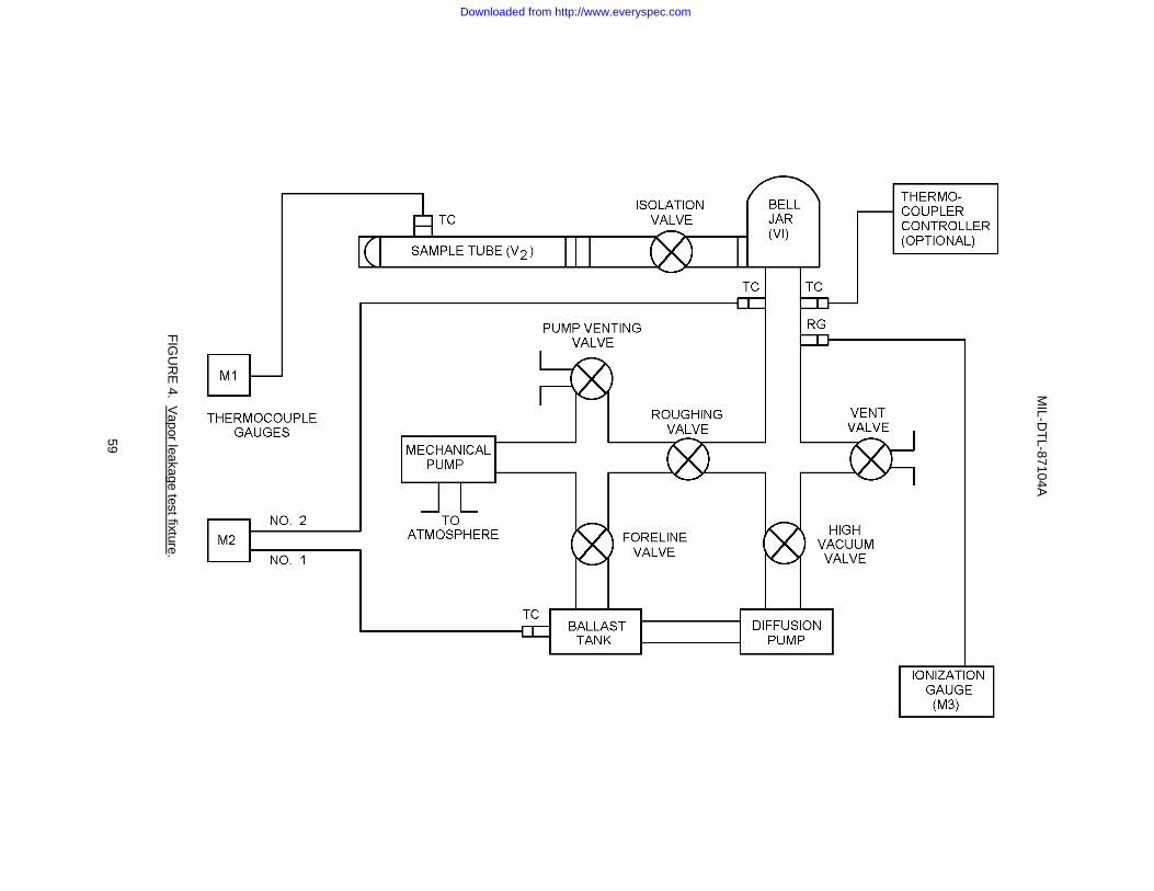
MIL-D
TL-87104A
59
FIG
UR
E 4. V
apor leakage test fixture .
Downloaded from http://www.everyspec.com

MIL-DTL-87104A
60
f. Step 6: When a multi-port connection is used, subject each sample to steps 1 through 5. g. Step 7: If the quantity (Px - Po) remains constant throughout the test period, a gross leak may exist.
Remove the suspect test sample from the sample tube and visually inspect the test sample for seal ruptures. If no seal ruptures are found, set the test sample aside for a period of at least 1 hour prior to retesting. The retest cycle shall consist of steps 1 through 3. Record Po and to.
h. Step 8: Read and record Px at 10-second intervals for a period of 2 minutes. Calculate the vapor leakage
rate for the coaxial assembly in accordance with step 5. NOTE: The retest cycle is required on braided outer conductor constructions. For solid outer conductor
constructions, an alternate test method, approved by the acquiring activity, may be used. 4.6.4.13.1.3 Accept-reject criteria (procedure I) (see 3.5.3.15). If at any time during the initial test cycle, or if applicable, the retest cycle, the coaxial assembly has a vapor leakage greater than that specified in the detail specification, the unit under test shall be considered to have failed the vapor leakage test. 4.6.4.13.2 Procedure II (immersion-leakage test). 4.6.4.13.2.1 Test setup. 4.6.4.13.2.1.1 Test equipment. An altitude chamber, or equivalent, and a tank of water shall be required. 4.6.4.13.2.1.2 Test conditions. The test conditions shall be as specified herein. Unless otherwise specified in the detail specification, the coaxial assembly shall be immersed in tap water open-ended. 4.6.4.13.2.2 Procedural steps. Procedure II shall be conducted in accordance with the following steps: a. Step 1: Subject the coaxial assembly to examination of product, procedure II (see 4.6.1.2). b. Step 2: Subject the coaxial assembly to VSWR, procedure II (see 4.6.2.1.2). c. Step 3: Immerse the coaxial assembly in tap water and place in the altitude chamber. d. Step 4: Reduce the absolute pressure of the air above the liquid to approximately 1 inch of mercury and
maintain for 10 minutes, or until air bubbles substantially cease to be given off by the liquid, whichever is longer. Increase the absolute pressure to 2.5 inches of mercury and maintain for 15 minutes.
e. Step 5: After the chamber has been allowed to return to ambient pressure, remove the coaxial assembly
from the chamber and dry with a clean, lint-free cloth. f. Step 6: Subject the coaxial assembly to VSWR, procedure II. g. Step 7: Subject the coaxial assembly to examination of product, procedure IV (see 4.6.1.4). 4.6.4.13.2.3 Accept-reject criteria (procedure II) (see 3.5.3.15). The test sample shall be considered as having passed the immersion-leakage test if: a. There was no evidence of bubbles coming from within the equipment while submerged. b. The coaxial assembly successfully passes the accept-reject criteria specified in 4.6.2.1.2.5 and 4.6.1.4.1. 4.6.4.13.3 Procedure III (leakage test). 4.6.4.13.3.1 Test setup. 4.6.4.13.3.1.1 Test equipment. An altitude chamber, or equivalent, and a tank of water shall be required.
Downloaded from http://www.everyspec.com

MIL-DTL-87104A
61
4.6.4.13.3.1.2 Test conditions. The test conditions shall be as specified herein. Unless otherwise specified in the detail specification, the coaxial assembly shall be immersed in tap water without a cover on connectors. 4.6.4.13.3.2 Procedural steps. Procedure III shall be conducted in accordance with the following steps: a. Step 1: Completely immerse the coaxial assembly in tap water and place in the altitude chamber. b. Step 2: Reduce the absolute pressure of the air above the liquid to approximately 1 inch of mercury and
maintain for 10 minutes, or until air bubbles substantially cease to be given off by the liquid, whichever is longer. Increase the absolute pressure to 2.5 inches of mercury and maintain for 15 minutes.
c. Step 3: After the chamber has been allowed to return to ambient pressure, remove the coaxial assembly
from the chamber and dry with a clean, lint-free cloth. 4.6.4.13.3.3 Accept-reject criteria (procedure III) (see 3.5.3.15). The test sample shall be considered as having passed the leakage test if there was no evidence of bubbles coming from within the equipment while submerged. 4.7 Reliability tests (see 3.4.7.6.2). When required by the acquiring activity, reliability tests must be conducted. 4.8 Maintainability demonstration. When required by the acquiring activity, maintainability demonstration shall be conducted (see 3.4.6, 6.2 and 6.5). 4.9 Test data preparation. 4.9.1 Test procedures. Unless otherwise specified by the acquiring activity, the contractor shall prepare detailed test procedures, subject to the approval of the acquiring activity prior to the start of the first article or the conformance test program. The acquiring activity shall reserve the right to modify the tests or require any additional tests deemed necessary to determine compliance with the requirements of this document. Unless otherwise specified, the approved test procedures shall be considered a part of this specification and a separate test procedure shall be required for each different test. 4.9.2 Test reports. Unless otherwise specified by the acquiring activity, the contractor must prepare a test report, with the additions and exceptions specified herein, for each test procedure. 4.9.2.1 Examination of product test reports. 4.9.2.1.1 Procedure I. The test report for procedure I shall include data to show compliance with each and every characteristic of the equipment examined. This shall include measured data to show compliance with all physical requirements. Certificates of compliance may be substituted for data providing they contain positive identification, or a totally defining description, of the materials, processes, finishes, or design characteristics being certified. 4.9.2.1.2 Procedures II and IV. A detailed description of the exact condition of the equipment shall be recorded on the test data sheet for procedures II and IV. 4.9.2.1.3 Procedure III. A copy of all X-ray photographs taken along with the laboratory test report shall be submitted with the test report for procedure III. 4.9.2.1.4 Procedure V. The test report for procedure V shall include signed certifications that the design, construction, material, finishes, and processes are identical to the equipment that was subjected to the first article test program. 4.9.2.1.5 Procedure VI. The test report for procedure VI shall include data to define every characteristic of the cable examined. This shall include measured data for all physical parameters. Certificates of compliance may be substituted for data providing they contain positive identification of, or a totally defining description of the materials, processes, finishes, or design characteristics being certified. 4.9.2.2 Contractor's certification. Each test report shall contain the following certification, which shall be signed by a responsible officer of the contractor's organization.
Downloaded from http://www.everyspec.com

MIL-DTL-87104A
62
The data contained in this report has been obtained in accordance with the requirements specified in (specific test procedure, applicable revision, and date) and has been reviewed, verified, and certified to be as stated. The unit under test is certified to have (passed/failed) this test. 4.9.2.3 Government certification. Each test report shall contain the following certification, which shall be signed by the cognizant Government representative. This test was performed under my cognizance and, to the best of my knowledge, the test and all data contained in the test report was accomplished in accordance with applicable test procedure. 4.9.2.4 Conformance test certification. In addition, each conformance test report shall contain the following certification which shall be signed by a responsible officer of the contractor's organization. The design, construction, materials, finishing, and processes are identical to the model that was subjected to the first article test program (see 4.4 and 4.6). 4.9.2.5 Conformance test results. The results of conformance testing on coaxial cable shall be submitted with the sampling plan test report for the assembly. 5. PACKAGING 5.1 Packaging. For acquisition purposes, the packaging requirements shall be as specified in the contract or order (see 6.2). When packaging of materiel is to be performed by DoD or in-house contractor personnel, these personnel need to contact the responsible packaging activity to ascertain packaging requirements. Packaging requirements are maintained by the Inventory Control Point's packaging activities within the Military Service or Defense Agency, or within the military service's system commands. Packaging data retrieval is available from the managing Military Department's or Defense Agency's automated packaging files, CD-ROM products, or by contacting the responsible packaging activity. 6. NOTES: (This section contains information of a general or explanatory nature that may be helpful, but is not mandatory.) 6.1 Intended use. The coaxial assemblies covered by this general specification are intended for use with airborne electronic systems. 6.2 Acquisition requirements. Acquisition documents should specify the following: a. Title, number, and date of this specification or the detail specification sheet. b. First article test program. (1) Number of first article test samples. (2) Point of inspection. c. Conformance test program. (1) Sample plan(s) required (see 4.5.2). (2) Point of inspection. d. Test level and test plan for reliability testing, if required (see 4.7). e. Test method for maintainability demonstrations, if required (see 4.8).
Downloaded from http://www.everyspec.com

MIL-DTL-87104A
63
f. Selection of applicable levels of preservation and packaging, and packing. g. Reliability requirements, when applicable (see 3.4.7). h. Maintainability requirements, when applicable (see 3.4.6, 4.8 and 6.5). i. Safety requirements, when applicable (see 3.4.8). j. Human engineering requirements, when applicable (see 3.4.9). 6.3 First article inspection. The activity responsible for the first article inspection is Defense Supply Center, Columbus, Code DSCC-VQE, Columbus OH 43216-5000 and information pertaining to first article approval of products may be obtained from that activity ([email protected]). 6.4 Definitions. 6.4.1 Test discrepancy. Test discrepancy should be construed to be a condition whereby the equipment fails the accept-reject criteria for a given test due to accidental damage, documentation error, installation error, instrumentation malfunction, or failure of the test equipment or facility. 6.4.2 Damage, deterioration, and degradation of performance. 6.4.2.1 Damage: Damage must be construed to include such items as: cracks or fractures of external or internal structure, irreversible strain or deformation of the structure, fatigue embrittlement of any component, damaged threads, hairline cracks, cracks or flaws in epoxied or soldered joints, or change in tolerance limits of any internal or external components beyond specified tolerance limits. If the equipment cannot be completely examined both internally and externally, it will be necessary to accomplish the examination by radiographic means. 6.4.2.2 Deterioration: Deterioration must be construed to include such items as: discoloration as would result from inadequate finish, corrosion, fraying, plating or paint blisters, pitting or peeling, warped or bent parts, excessive wear, fungus growth, and evidence of moisture inside the equipment. 6.4.2.3 Degradation of performance. Degradation of performance must be construed to include any condition that results in the loss of performance beyond specification limits. 6.4.3 Band of doubt: A VSWR value must be considered to be in the band of doubt if the measured VSWR = the maximum allowable VSWR" +0.08* (the maximum VSWR = 1). If the VSWR values fall within the band of doubt, a frequency band of ± 10 percent must be investigated about the point. (*0.10 for frequencies above 12.0 GHz.) 6.4.4 Insertion loss: The insertion loss must be defined as the ratio of the power (P1) absorbed by a given load from a generator and the power (P2) absorbed by a given load from a generator after insertion of the sample between the generator and the load, must be primarily made up of two factors: (1) the mismatch losses and (2) dissipative losses. The insertion loss must be expressed in dB and shall be equal to:
6.4.5 Fine structure variation: A periodic or abrupt change that appears in the plotted measurement of insertion loss versus frequency (see figure 5). 6.4.6 Peak-to-peak variation: The variation in the characteristic impedance plot caused by mismatches or imperfections in the coaxial assembly (see figure 6). 6.4.7 Critical resonant frequency. A critical resonant frequency is that frequency at which any point on the test sample is observed to have a maximum amplitude more than twice that of the support points.
)(
)(10
2
1log10
P
P
Downloaded from http://www.everyspec.com

MIL-DTL-87104A
64
6.4.8 Resonant frequency: A resonant frequency is that frequency which has an amplitude that is greater than 1.5 times the amplitude of the support points. 6.4.9 Coaxial assembly classifications. a. Class 1: A class 1 (flexible construction) coaxial assembly is one where, during installation, bending is
required to facilitate running long lengths, where attachment to shock mounted equipment is required, and where large angular displacements are encountered during service and maintenance conditions.
b. Class 2: A class 2 (semiflexible construction) coaxial assembly is one where, during installation, bending or
forming is required to facilitate running long lengths but where attachment to shock-mounted equipment is not required. Class 2 coaxial assemblies are not intended for applications requiring continuous flexure in service.
c. Class 3: A class 3 (rigid construction) coaxial assembly is one that is formed during manufacturing and
cannot withstand further bending or forming during installation or service without performance degradation. 6.4.10 Cable assembly types. 6.4.10.1 Type A: A type A cable assembly is defined as a cable assembly which has a straight male connector at both ends. 6.4.10.2 Type B: A type B cable assembly is defined as a cable assembly which has a straight male connector at one end and a right angle male connector at the other end. 6.4.10.3 Type C: A type C cable assembly is defined as a cable assembly which has a straight male connector at one end and a straight female bulkhead connector at the other end. 6.4.10.4 Type D: A type D cable assembly is defined as a right angle male connector on one end and a straight female bulkhead connector on the other end. 6.4.11 Coaxial component: A coaxial device capable of transmitting RF energy in the TEM mode over distances large in comparison to the wavelength of energy. A coaxial component may be terminated by either an interface component or an intermediate interface component. 6.4.12 Interface component: The part of a coaxial assembly which provides a mechanical and electrical mate between the coaxial component and other equipment. The interface component terminates in a primary interface and is permanently attached to its appropriate coaxial component. 6.4.13 Intermediate interface component. The part of a coaxial assembly which provides a mechanical and electrical mate between a coaxial component and a replaceable interface component. The intermediate interface component terminates in an intermediate interface and is permanently attached to its appropriate coaxial component. 6.4.14 Replaceable interface component: The part of a coaxial assembly which provides a mechanical and electrical mate between an intermediate interface component and other equipment. The replaceable interface component is removable as a unit and terminates in an intermediate interface and a primary interface.
Downloaded from http://www.everyspec.com

MIL-DTL-87104A
65
TYPICAL INSERTION LOSS CURVE
FIGURE 5. Typical fine structure variation.
Downloaded from http://www.everyspec.com

MIL-DTL-87104A
66
FIGURE 6. Typical impedance plot.
Downloaded from http://www.everyspec.com

MIL-DTL-87104A
67
6.4.15 Intermediate interface: The electrical and mechanical transition between an intermediate interface component and a replaceable interface component. The intermediate interface does not provide the final transition from the coaxial component to external equipment. 6.4.16 Primary interface: The final electrical and mechanical transition between a coaxial assembly and external equipment. The primary interface may be part of an interface component or a replaceable interface component. 6.4.17 Outline dimensions: Outline dimensions, for the purpose of this document, are defined as those that describe the physical size and shape of a coaxial assembly and, if applicable, locate required markings. 6.4.18 Responsible officer: For the purpose of this document, a responsible officer refers to any person who can legally bind the company in contractual matters. 6.4.19 Subject term (key word) listing. abrasion resistance altitude compliance cable cold bend connectors corona corrosion resistance first article flexible flexing endurance heat aging insertion loss interface resonance endurance RF leakage solder temperature-altitude tensile load torque VSWR 6.5 Maintainability demonstration. Experience has shown that conducting maintainability demonstration in accordance with MIL-HDBK-470 satisfies the requirements of this specification (see 3.4.6, 4.8 and 6.2). 6.6 Threaded parts (see 3.3.1.10). Experience has shown that threaded parts in accordance with MIL-HDBK-454, guideline 12 satisfy the requirements of this specification. 6.7 Environmentally preferable marterial. Environmentally preferable materials should be used to the maximum extent possible to meet the requirements of this specification. Table VI lists the Environmental Protection Agency (EPA) top seventeen hazardous materials targeted for major usage reduction. Use of these materials should be minimized or eliminated unless needed to meet the requirements specified herein (see Section3).
Table VI. EPA top seventeen hazardous materials. Benzene Dichloromethane Tetrachloroethylene Cadmium and Compounds Lead and Compounds Toluene Carbon Tetrachloride Mercury and Compounds 1,1,1 - Trichloroethane Chloroform Methyl Ethyl Ketone Trichloroethylene Chromium and Compounds Methyl Isobutyl Ketone Xylenes Cyanide and Compounds Nickel and Compounds
6.8 Changes from previous issue. Marginal notations are not used in this revision to identify changes with respect to the previous issue due to the extent of the changes.
Downloaded from http://www.everyspec.com

MIL-DTL-87104A
68
Custodians: Preparing activity: Air Force - 11 DLA - CC DLA - CC (Project 5985-1292) NOTE: The activities listed above were interested in this document as of the date of this document. Since organizations and responsibilities can change, you should verify the currency of the information above using the ASSIST Online database at www.dodssp.daps.mil.
Downloaded from http://www.everyspec.com


![[NOT MEASUREMENT SENSITIVE] SUPERSEDING MIL-P-197Heveryspec.com/MIL-SPECS/MIL-SPECS-MIL-DTL/download.php?spec=… · [not measurement sensitive] mil-dtl-197j 9 july 2000 superseding](https://img.dokumen.tips/doc/110x75/5b80c51f7f8b9af7088e17c6/not-measurement-sensitive-superseding-mil-p-not-measurement-sensitive-mil-dtl-197j.jpg)