Embed Size (px)
Citation preview

INC 112 Basic Circuit Analysis
Week 7
Introduction to
AC Current
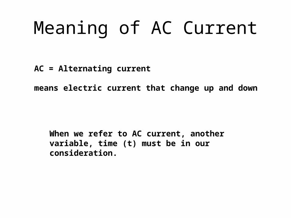
Meaning of AC Current
AC = Alternating current
means electric current that change up and down
When we refer to AC current, another variable, time (t) must be in our consideration.
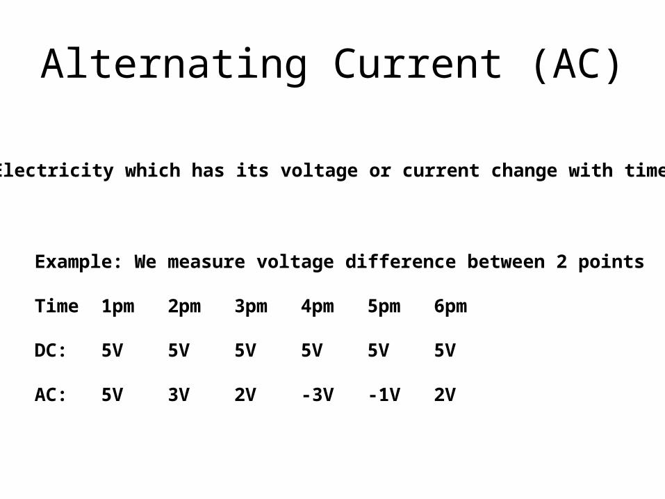
Alternating Current (AC)
Electricity which has its voltage or current change with time.
Example: We measure voltage difference between 2 points
Time 1pm 2pm 3pm 4pm 5pm 6pm
DC: 5V 5V 5V 5V 5V 5V
AC: 5V 3V 2V -3V -1V 2V
Signals
Signal is an amount of something at different time, e.g. electric signal.
Signals are mentioned is form of1.Graph2.Equation

Graph Voltage (or current) versus time
V (volts)
t (sec)
v(t) = sin 2t
1st Form
2nd Form
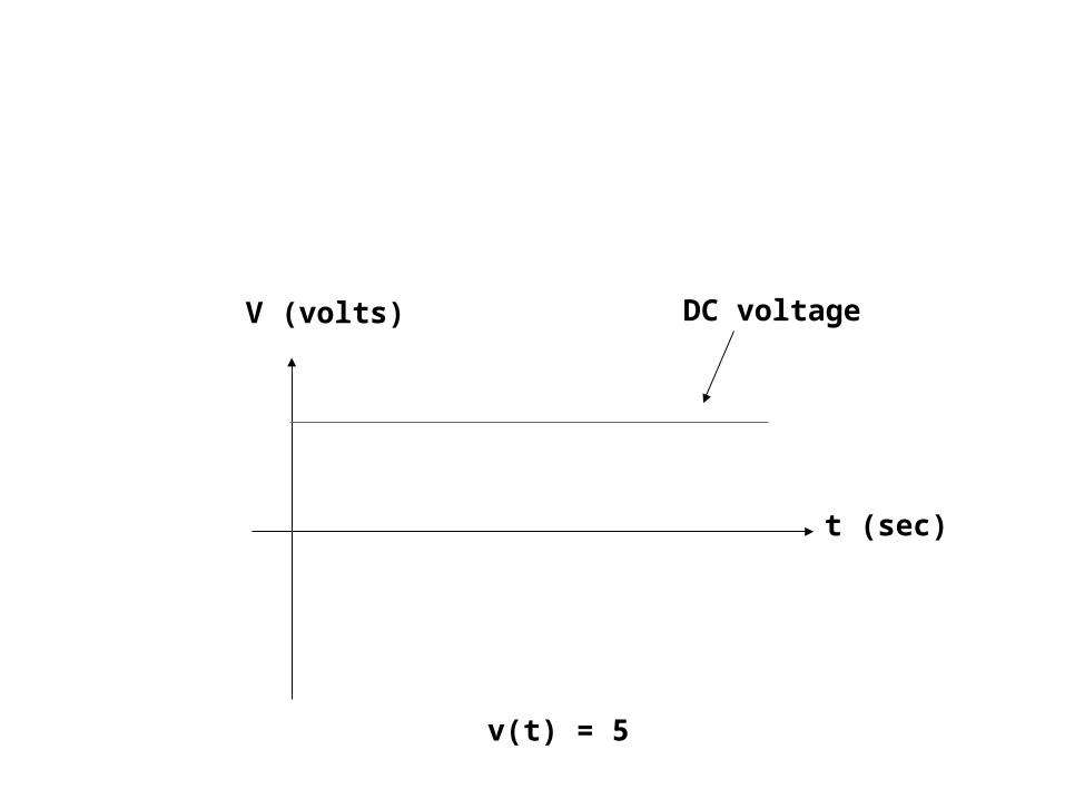
V (volts)
t (sec)
DC voltage
v(t) = 5

Course requirement of the2nd half
Students must know voltage, current, power at any point in the given circuits at any time.
e.g.
What is the current at point A?What is the voltage between point B and C at 2pm?What is the current at point D at t=2ms?
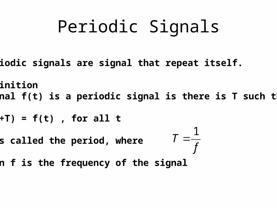
Periodic Signals
Periodic signals are signal that repeat itself.
DefinitionSignal f(t) is a periodic signal is there is T such that
f(t+T) = f(t) , for all t
T is called the period, where
when f is the frequency of the signal
fT
1

Example:
v(t) = sin 2t
Period = π Frequency = 1/π
v(t+π) = sin 2(t+π) = sin (2t+2π) = sin 2t(unit: radian)
Note: sine wave signal has a form of sin ωt where ω is the angular velocity with unit radian/sec

0 0.01 0.02 0.03 0.04 0.05 0.06 0.07
-1
-0.8
-0.6
-0.4
-0.2
0
0.2
0.4
0.6
0.8
1
0 0.01 0.02 0.03 0.04 0.05 0.06 0.07
-1
-0.8
-0.6
-0.4
-0.2
0
0.2
0.4
0.6
0.8
1
Sine waveSquare wave
0 0.001 0.002 0.003 0.004 0.005 0.006 0.007 0.008 0.009 0.01-0.8
-0.6
-0.4
-0.2
0
0.2
0.4
0.6
0.8
1
-5 -4 -3 -2 -1 0 1 2 3 4 5-0.4
-0.2
0
0.2
0.4
0.6
0.8
1

Fact:
Theorem: (continue in Fourier series, INC 212 Signals and Systems)
“Any periodic signal can be written in form of a summationof sine waves at different frequency (multiples of the frequency of the original signal)”
e.g. square wave 1 KHz can be decomposed into a sum of sine wavesof reqeuency 1 KHz, 2 KHz, 3 KHz, 4 KHz, 5 KHz, …
.....)2.14sin(5.0)2.03sin(1)5.02sin(3)3.0sin(8 tttt
Implication of Fourier Theorem
Sine wave is a basis shape of all waveform.
We will focus our study on sine wave.

Properties of Sine Wave
1. Frequency
2. Amplitude
3. Phase shift
These are 3 properties of sine waves.

Frequency
0 1 2 3 4 5 6 7 8 9 10-1
-0.8
-0.6
-0.4
-0.2
0
0.2
0.4
0.6
0.8
1
sec
volts
fT
1
Period ≈ 6.28, Frequency = 0.1592 Hz
period

Amplitude
0 1 2 3 4 5 6 7 8 9 10-1
-0.8
-0.6
-0.4
-0.2
0
0.2
0.4
0.6
0.8
1
sec
volts
Blue 1 voltsRed 0.8 volts

Phase Shift
0 1 2 3 4 5 6 7 8 9 10-1
-0.8
-0.6
-0.4
-0.2
0
0.2
0.4
0.6
0.8
1
)1sin(8.0
)sin(
ty
ty
red
blue
Period=6.28
PhaseShift =
1
Red leads blue 57.3 degree (1 radian) 3.57360
28.6
1
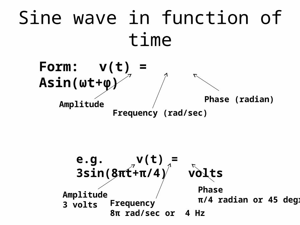
Sine wave in function of time
Form: v(t) = Asin(ωt+φ)
AmplitudeFrequency (rad/sec)
Phase (radian)
e.g. v(t) = 3sin(8πt+π/4) volts
Amplitude3 volts Frequency
8π rad/sec or 4 Hz
Phaseπ/4 radian or 45 degree

Basic Components
• AC Voltage Source, AC Current Source
• Resistor (R)
• Inductor (L)
• Capacitor (C)

AC Voltage SourceAC Current Source
AC AC
+
-
AC +-
AC
Voltage Source Current Source
AC
+
-
10sin(2πt + π/4)
เชน
Amplitude = 10VFrequency = 1HzPhase shift = 45 degree

AC
+
-
10sin(2πt + π/4) What is the voltage at t =1 sec ?
volts
v
07.7)4/sin(10
)4/2sin(10
)4/)1(2sin(10)1(

Resistors
Same as DC circuits
Ohm’s Law is still usable
V = IR
R is constant, therefore V and I have the same shape.

AC
+
-
10sin(2πt + π/4) 2Ω
i(t)
Find i(t)
)4/2sin(5)(2
)4/2sin(10)(
2)()4/2sin(10
)()(
tti
tti
tit
Rtitv
Note: Only amplitude changes, frequency and phase still remain the same.
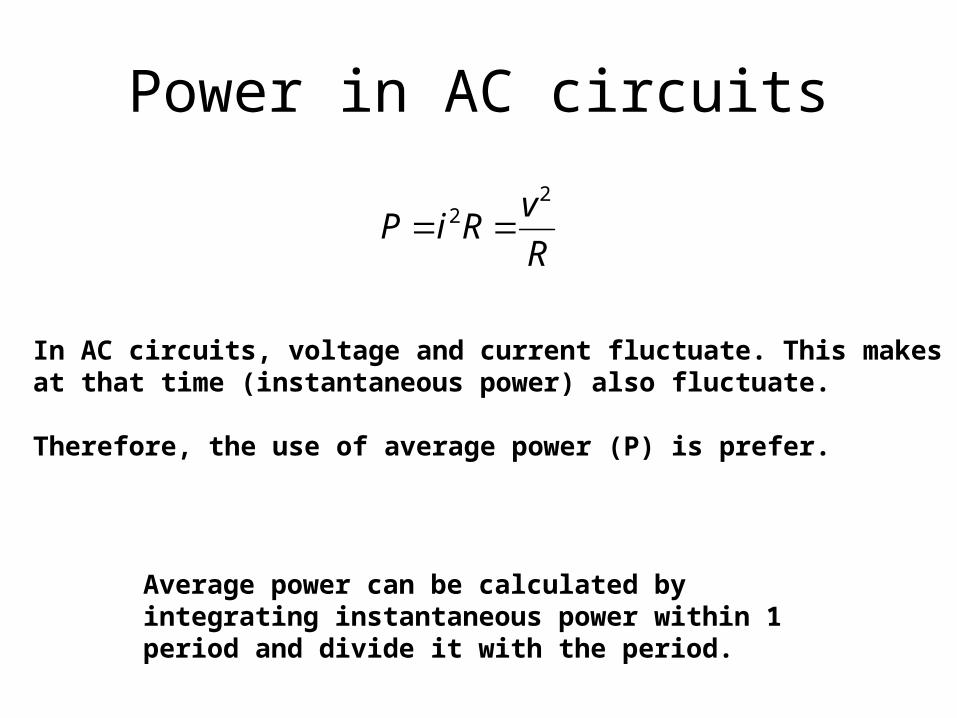
Power in AC circuits
R
vRiP
22
In AC circuits, voltage and current fluctuate. This makes powerat that time (instantaneous power) also fluctuate.
Therefore, the use of average power (P) is prefer.
Average power can be calculated by integrating instantaneous power within 1 period and divide it with the period.

)sin()( tAtv Assume v(t) in form Change variable of integration to θ
sinAv We get Then, find instantaneous power
R
A
R
vp
222 sin integrate from 0 to 2π
R
A
R
A
dA
dR
A
dR
AP
24
2sin
2
1
2
2
2cos1
2sin
2
sin2
1
22
0
2
2
0
22
0
22
2
0
22

Compare with power from DC voltage source
DC
AC
+
-
Asin(ωt+Ф) R
i(t)
AC
+
-A R
i(t)
R
AP
2
2
R
AP
2

Root Mean Square Value (RMS)
In DC circuitsR
VRIP
22
In AC, we define Vrms and Irms for convenient in calculating power
R
VRIP rms
rms
22 Note: Vrms and Irms are constant,
independent of time
For sine wave Asin(ωt+φ)2
_A
valuerms
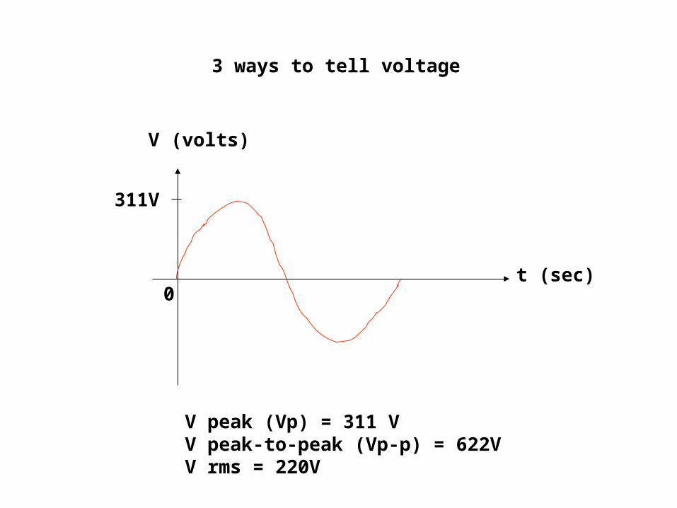
V (volts)
t (sec)
311V
V peak (Vp) = 311 VV peak-to-peak (Vp-p) = 622VV rms = 220V
3 ways to tell voltage
0

Inductors
i(t)
+ v(t) -
Inductance has a unit of Henry (H)
Inductors have V-I relationship as follows
dt
tdiLtv
)()( This equation compares to
Ohm’s law for inductors.
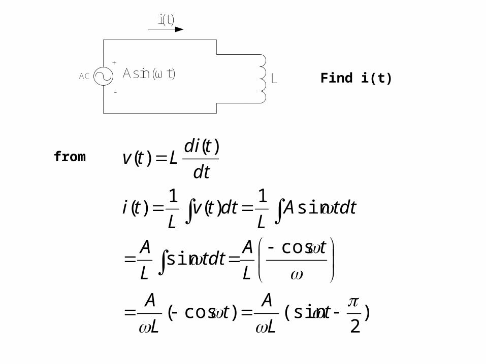
AC
+
-
Asin(ωt)
i(t)
L Find i(t)
)2
(sin)cos(
cossin
sin1
)(1
)(
)()(
tL
At
L
A
t
L
Atdt
L
A
tdtAL
dttvL
ti
dt
tdiLtvfrom
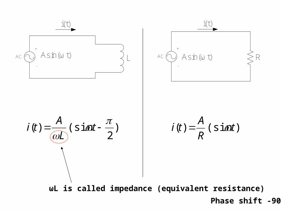
AC
+
-
Asin(ωt) R
i(t)
AC
+
-
Asin(ωt)
i(t)
L
)2
(sin)(
t
L
Ati )(sin)( t
R
Ati
ωL is called impedance (equivalent resistance)
Phase shift -90

Phasor Diagram of an inductor
v
i
Power = (vi cosθ)/2 = 0
Phasor Diagram of a resistor
v
i
Power = (vi cosθ)/2 = vi/2
Note: No power consumed in inductorsi lags v

DC Characteristics
i(t)
L1V1Ω
i(t)
1V1Ω
When stable, L acts as an electric wire.
dt
tdiLtv
)()(
When i(t) is constant, v(t) = 0

Capacitors
i(t)
+ v(t) -
Capacitance has a unit of farad (f)
dt
tdvCti
)()(
Capacitors have V-I relationship as follows
This equation compares to Ohm’s law for capacitors.

AC
+
-
Asin(ωt)
i(t)
C Find i(t)
)2
sin(1
)(cos
)sin()()(
t
C
A
tCAdt
tAdC
dt
tdvCti
Impedance (equivalent resistance)
Phase shift +90

Phasor Diagram of a capacitor
v
i
Power = (vi cosθ)/2 = 0
Phasor Diagram of a resistor
v
i
Power = (vi cosθ)/2 = vi/2
Note: No power consumed in capacitorsi leads v

DC Characteristics
i(t)
1V1Ω
C
i(t)
1V1Ω
When stable, C acts as open circuit.
When v(t) is constant, i(t) = 0
dt
tdvCti
)()(

Combination of Inductors
L1 L2 L1+L2
L1
L2
L1L2/(L1+L2)
21 LLLtotal
21
111
LLLtotal

Combination of Capacitors
C1 C2 C1C2/(C1+C2)
C1
C2
C1+C2
21 CCCtotal
21
111
CCCtotal

Linearity
Inductors and capacitors are linear components
dt
tdvCti
)()(
dt
tdiLtv
)()(
If i(t) goes up 2 times, v(t) will also goes up 2 timesaccording to the above equations

Transient Responseand Forced response

Purpose of the second half
• Know voltage or current at any given time
• Know how L/C resist changes in current/voltage.
• Know the concept of transient and forced response

Characteristic of R, L, C
• Resistor resist current flow
• Inductor resists change of current
• Capacitor resists change of voltage
L and C have “dynamic”

I
1V1Ω
I
2V1Ω
I = 1A I = 2A
Voltage source change from 1V to 2V immediatelyDoes the current change immediately too?

Voltage
Current
time
time
1V
2V
1A
2A
AC voltage

I
L1V1Ω
I
L2V1Ω
I = 1A I = 2A
Voltage source change from 1V to 2V immediatelyDoes the current change immediately too?

Voltage
Current
time
time
1V
2V
1A
2A
Forced Response
Transient Response + Forced Response
AC voltage
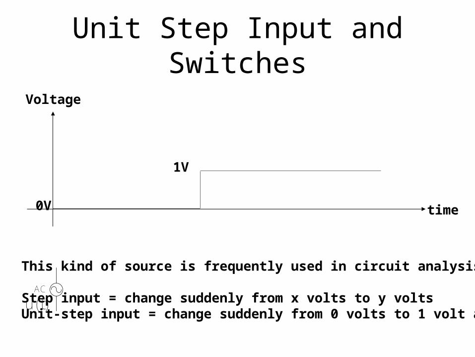
Unit Step Input and Switches
Voltage
time0V
1V
This kind of source is frequently used in circuit analysis.
Step input = change suddenly from x volts to y voltsUnit-step input = change suddenly from 0 volts to 1 volt at t=0
AC
u(t)
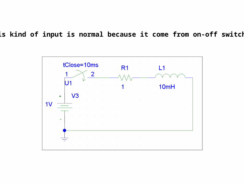
This kind of input is normal because it come from on-off switches.

PSPICE Example
• All R circuit, change R value
• RL circuit, change L
• RC circuit, change C

I am holding a ball with a rope attached, what is the movement of the ball ifI move my hand to another point?
Movements
1. Oscillation
2. Forced position change
Pendulum Example
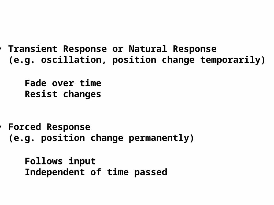
• Transient Response or Natural Response (e.g. oscillation, position change temporarily)
Fade over timeResist changes
• Forced Response (e.g. position change permanently)
Follows inputIndependent of time passed

Forced response Natural responseat different time
Mechanical systems are similar to electrical system

i(t)
LR
ACconnect
i(t)
StableChanging
Transient Analysis Phasor Analysis
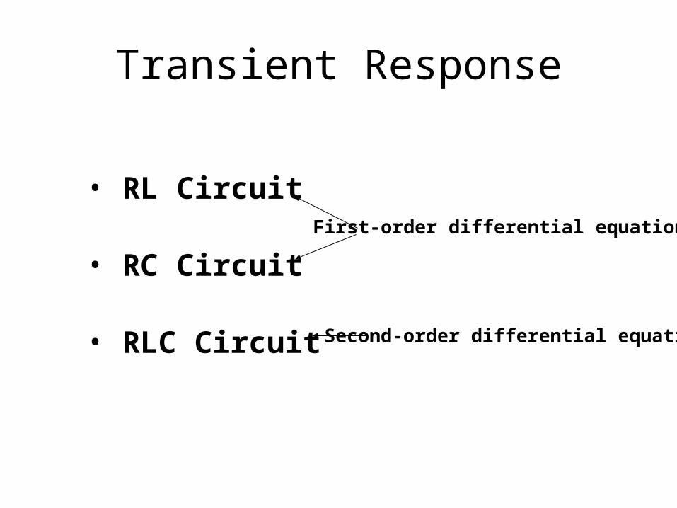
Transient Response
• RL Circuit
• RC Circuit
• RLC Circuit
First-order differential equation
Second-order differential equation