Embed Size (px)
Citation preview

INSTALLATION GUIDEInBio Pro Series Access Control Panels
Date: June, 2016Version: 1.2
INSTALLATION GUIDE

2
InBio Pro Series Access Control Panels INSTALLATION guIDE
What’s in the Box
4 Diode2 Screws & Anchors 2 Screwdriver

3
InBio Pro Series Access Control Panels INSTALLATION GUIDE
CONTENT
ContentsWhat’s in the Box ......................................................................2Optional accessories ..............................................................4Safety Precautions....................................................................5Product PIN Diagram .............................................................6LED Indicators .............................................................................7Product Dimension .................................................................8Installation of Panel & Cabinet ........................................9Wiring Legend .........................................................................10Power Wiring Diagram .....................................................11
Without Backup Battery ........................................................ 11With Backup Battery ............................................................... 11
RS485 Fingerprint Reader Connection..................12DIP Switch Setting for RS485 Reader ......................13Wiegand Connection .........................................................14REX Connections ...................................................................15Lock Connection ...................................................................16
Connecting a Lock with External to Power Supply ....... 16Switching Dry Contact to Wet Contact ............................ 17
Lock Connection ...................................................................18Normally Open Lock Powered From Lock Terminal ...... 18Normally Closed Lock Powered From Lock Terminal .... 18
Aux. I/O Connection ..........................................................19Aux. Input Connection .......................................................... 19Aux. Output Connection ....................................................... 19
Ethernet Connection .........................................................20LAN Connection ...................................................................... 20Direct connection ................................................................... 20
RS485 Connection ..............................................................21RS485 Connection ..............................................................22
Restore factory setting ........................................................... 22
DIP Switch Setting ................................................................23RS485 Address .......................................................................... 23Terminal Resistance ................................................................ 23
Installation Diagram ............................................................24Troubleshooting ....................................................................25PC 485 Setting Table ...........................................................26Electrical Specifications ...................................................28Specifications ..........................................................................29
ZKBioSecurity Software
4
InBio Pro Series Access Control Panels INSTALLATION guIDE
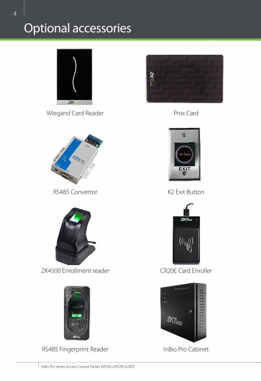
Optional accessories
Wiegand Card Reader
ZK4500 Enrollment reader
RS485 Convertor
RS485 Fingerprint Reader
Prox Card
CR20E Card Enroller
K2 Exit Button
InBio Pro Cabinet
5
InBio Pro Series Access Control Panels INSTALLATION guIDE
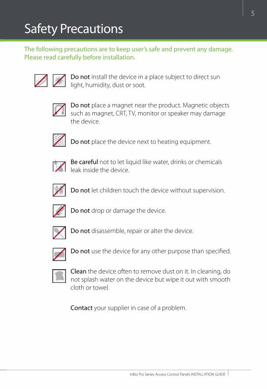
Safety PrecautionsThe following precautions are to keep user’s safe and prevent any damage. Please read carefully before installation.
Do not install the device in a place subject to direct sun light, humidity, dust or soot.
Do not place a magnet near the product. Magnetic objects such as magnet, CRT, TV, monitor or speaker may damage the device.
Do not place the device next to heating equipment.
Be careful not to let liquid like water, drinks or chemicals leak inside the device.
Do not let children touch the device without supervision.
Do not drop or damage the device.
Do not disassemble, repair or alter the device.
Do not use the device for any other purpose than specifi ed.
Clean the device often to remove dust on it. In cleaning, do not splash water on the device but wipe it out with smooth cloth or towel.
Contact your supplier in case of a problem.
6
InBio Pro Series Access Control Panels INSTALLATION GUIDE
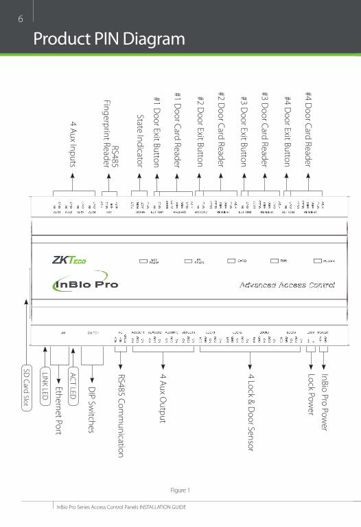
Product PIN Diagram
4 Aux Inputs
State Indicator
#1 Door Card Reader
#1 Door Exit Button
RS485 Fingerprint Reader
#2 Door Card Reader
#2 Door Exit Button
#3 Door Card Reader
#3 Door Exit Button
#4 Door Card Reader
#4 Door Exit Button
4 Lock & Door Sensor
4 Aux Output
RS485 Comm
unication
DIP Sw
itches
Ethernet Port
Lock Power
InBio Pro Power
LINK LED
ACT LED
SD Card Slot
Figure 1
7
InBio Pro Series Access Control Panels INSTALLATION guIDE
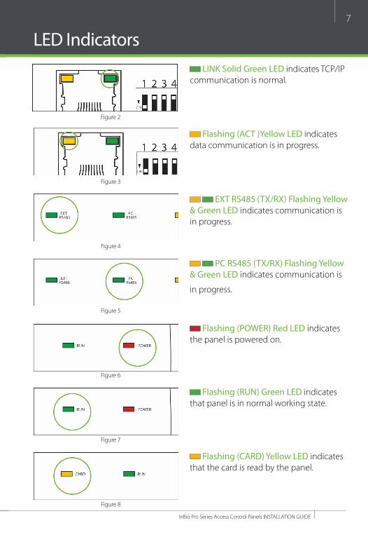
LED Indicators LINK Solid Green LED indicates TCP/IP
communication is normal.
Flashing (ACT )Yellow LED indicates data communication is in progress.
EXT RS485 (TX/RX) Flashing Yellow & Green LED indicates communication is in progress.
PC RS485 (TX/RX) Flashing Yellow & Green LED indicates communication is
in progress.
Flashing (POWER) Red LED indicates the panel is powered on.
Flashing (RUN) Green LED indicates that panel is in normal working state.
Flashing (CARD) Yellow LED indicates that the card is read by the panel.
Figure 2
Figure 3
Figure 4
Figure 5
Figure 6
Figure 8
Figure 7

8
InBio Pro Series Access Control Panels INSTALLATION guIDE
Product Dimension
Figure 10
InBio160Pro InBio260Pro InBio460Pro
InBio Pro- Metal Cabinet
Figure 9
8.89 in (226 mm)
7.125 in (181 mm)
1.42 in (36 mm)4.17 in (106 mm)4.17 in (106 mm)4.17 in (106 mm)
15.7 in (400 mm)
13 in(330 mm)
3.56 in (90.5 mm)

9
InBio Pro Series Access Control Panels INSTALLATION guIDE
Installation of Panel & Cabinet
Cable Conduit(Punch hole for cables)
Temper Switch
InBio Pro Panel
heat Dissipation grill
Power Supply
Backup Battery
Mounting holesState Indicators Inserting Panel to Rail
Mounting Rail
We recommend drilling the mounting plate screws into solid wood (i.e. stud/beam). If a stud/beam cannot be found, then use the supplied drywall plastic mollies (anchors).
Step 1 Pass the cable through holes
Step 2 Mount the Metal Cabinet
Step 3Insert the InBio Pro Panel as it shown
Figure 11
Figure 12
1
2
10
InBio Pro Series Access Control Panels INSTALLATION guIDE
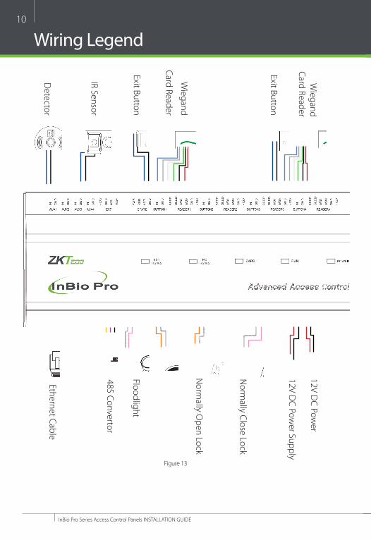
Wiring Legend
Detector
Ethernet Cable
IR Sensor
485 Convertor
Exit ButtonFloodlight
Wiegand
Card Reader
Exit Button
Norm
ally Open Lock
Norm
ally Close Lock
Wiegand
Card Reader12V D
C Power Supply
12V DC Pow
er
Figure 13

11
InBio Pro Series Access Control Panels INSTALLATION guIDE
Power Wiring Diagram
Without Backup Battery
With Backup Battery
Switching Power Supplyground
groundSwitching Power Supply
Figure 15
Figure 14
12
InBio Pro Series Access Control Panels INSTALLATION guIDE
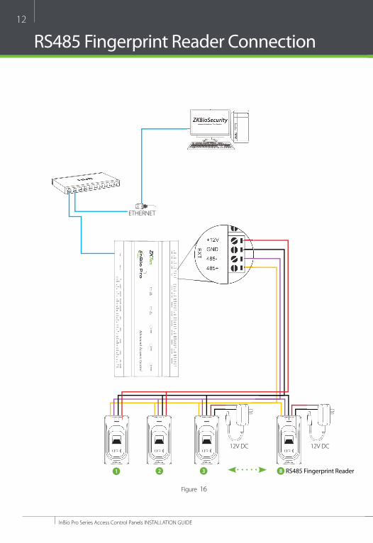
RS485 Fingerprint Reader Connection
12V DC12V DC
EThERNET
1 2 3 8 RS485 Fingerprint Reader
Figure 16
13
InBio Pro Series Access Control Panels INSTALLATION guIDE
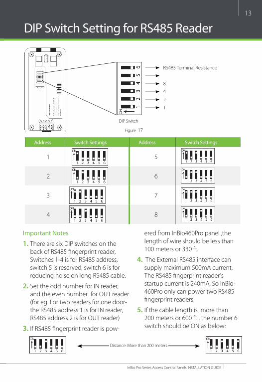
DIP Switch Setting for RS485 Reader
DIP Switch
Figure 17
RS485 Terminal Resistance
8
4
2
1
Address Switch Settings Address Switch Settings
1 5
2 6
3 7
4 8
Important Notes
1. There are six DIP switches on the back of RS485 fi ngerprint reader, Switches 1-4 is for RS485 address, switch 5 is reserved, switch 6 is for reducing noise on long RS485 cable.
2. Set the odd number for IN reader, and the even number for OuT reader (for eg. For two readers for one door- the RS485 address 1 is for IN reader, RS485 address 2 is for OuT reader)
3. If RS485 fi ngerprint reader is pow-
ered from InBio460Pro panel ,the length of wire should be less than 100 meters or 330 ft.
4. The External RS485 interface can supply maximum 500mA current, The RS485 fi ngerprint reader’s startup current is 240mA. So InBio-460Pro only can power two RS485 fi ngerprint readers.
5. If the cable length is more than 200 meters or 600 ft , the number 6 switch should be ON as below:
Distance: More than 200 meters

14
InBio Pro Series Access Control Panels INSTALLATION guIDE
Wiegand Connection
Wiegand Card Reader
Figure 18
Beeper
green LED
Wiegand D1
Wiegand D0
gND
DC+(6-14V)

15
InBio Pro Series Access Control Panels INSTALLATION guIDE
REX Connections
ZK ABK Exit Button
K2 Exit Switch
Separate Power Supply
unused
NO
BuTTON
COMgND
12V DC(+)12V DC( - )
Figure 19
Separate Power Supply

16
InBio Pro Series Access Control Panels INSTALLATION guIDE
Lock Connection
Connecting a Lock with External to Power Supply (Dry Contact)
FR107Diode
gND
gND
SensorSensor
12V DC
Door Contact
EThERNET
Figure 20
Sensor
-
+

17
InBio Pro Series Access Control Panels INSTALLATION guIDE
Switching Dry Contact to Wet Contact
Important Notes:
The factory default jumper setting is set as dry mode. If you want to power the lock from the panel, you must take the following steps:
1. Take apart the cover of InBio460Pro. Push the tab inward (see fi gure 21)
2. Select the appropriate lock relay and fi nd its jumpers
3. Take off the jumpers and change to
4. Connect the lock as show in the diagram, (see fi gure 23 and 24)
Back of InBio460Pro Select one Relay
Default setting1, 2 - 3, 4
Take off jumpers Jumpers Plug Jumpers2, 3 - 4, 5
Figure 22
Figure 21

18
InBio Pro Series Access Control Panels INSTALLATION guIDE
Lock Connection
Normally Open Lock Powered From Lock Terminal (Wet Contact)
Normally Closed Lock Powered From Lock Terminal (Wet Contact)
12V DC
12V DC
12V DC
12V DC
gND
gND
FR107Diode
FR107Diode
gND
gND
EThERNET
EThERNET
Figure 23
Figure 24
16 or 18 AWG shielded cable recommended
-
+
-
+

19
InBio Pro Series Access Control Panels INSTALLATION guIDE
Aux. I/O Connection
Aux. Input Connection
Aux. Output Connection
12V DC
12V DC
gND
gND
EThERNET
Figure 26
Figure 25
EThERNET

uSB uSB
uSBuSB
Direct connectionTo connect InBio Pro Panel with a PC directly, connect both devices with a straight network cable. As the InBio Pro Panel supports auto MDI/MDIX, it is not necessary to use a crossover type cable.
CR20E Card Issuer ZK4500 Enrollment reader
ZK4500 Enrollment readerCR20E Card Issuer
EThERNET
EThERNET
20
InBio Pro Series Access Control Panels INSTALLATION guIDE
Ethernet Connection
LAN ConnectionImportant Notes:
1. Both 10Base-T and 100Base-T are supported
2. This cable distance must be less than 330 ft. (100m)
3. For cable length of more than 330 ft. (100m). use huB to amplify the signal.
Figure 27
Figure 28
CAT5e or CAT6 ethernet cable recommended

#1 InBio Pro Panel
RS485 --RS485 +gND
#2 InBio Pro Panel #63 InBio Pro Panel
21
InBio Pro Series Access Control Panels INSTALLATION guIDE
RS485 Connection
Important Notes:
1. RS485 communication wires should be a shielded twisted pair cable. RS485 communication wires should be connected in a bus cascade topology instead of a star topology, to achieve a better shielding eff ect by reducing signal refl ection during communications.
2. A single RS485 bus can connect up to 63 access control panels, but preferably 32 is recommended maximum.
3. To eliminate signal attenuation in communication cables and suppress inter-ference, if the bus is longer than 200 meters, set the number 8 DIP switch to the ON position. This is equivalent to a parallel connection of one 120 ohm resistance between the 485+ and 485- lines.
SINgLE InBio Pro Panel MuLTI InBio Pro Panels
Incorrect RS485 connections
Distance: More than 200 meters
RS485 --RS485 +gND
RS485 --RS485 +gND
x
x
Figure 29
Figure 30
Figure 31
#1 InBio Pro Panel #2 InBio Pro Panel #63 InBio Pro Panel
#1 InBio Pro Panel #2 InBio Pro Panel #63 InBio Pro Panel

22
InBio Pro Series Access Control Panels INSTALLATION guIDE
RS485 Connection
1
2
4
8
16
32
Restore Factory Setting
RS485 Terminal Resistance
Restore factory setting1. If you forget the IP address of the InBio Pro panel or the device does not work
normally, you can use the number 7 DIP switch to restore InBio Pro Panel to factory default settings. The parameters which gets reset are device IP address, communication password, gateway, and subnet mask.
2. The switch is OFF by default. When it is moved up and down for three times within 10 seconds and fi nally returned to OFF position, the factory settings will be restored after the access control panel is restarted.
To reset factory settingsTurn #7 switch ON and OFF
Repeat process 3 times
Figure 32
Figure 33

#63 InBio Pro Panel
=
23
InBio Pro Series Access Control Panels INSTALLATION guIDE
RS485 Address1. Number 1-6 are reserved to set the device number for RS485 communica-
tion. The code is binary, and the numbering starts from left to right. When the switch is set to ON position, it indicates 1 (on); when the switch is set down-wards, it indicates 0 (off ). For example, to set a device number 39=1+2+4+32, which corresponds to the binary code 111001, put number 1, 2, 3, and 6 to ON position, as illustrated below.
For more details, please check the table at the end of this document.
DIP Switch Setting
Terminal ResistanceNumber 8 is for setting the RS485 termination resistance. Putting the switch to ON position is equivalent to parallel connection of a 120 ohm termination resis-tance between 485+ and 485- lines.
120 ohm
Figure 34
Figure 35

24
InBio Pro Series Access Control Panels INSTALLATION guIDE
Installation Diagram
Sensor
CEILINg
INDOOROuTDOOR
InBio Pro Access Control Bundle
Electric Lock
Exit Button
Indoor Wiegand card readerOutdoor Wiegand card reader
Figure 36
Ethernet Communication wire
220/110 V Input
RS485 Network Communication wire

a. Connect the controller to the network or PC, start the browser, enter the IP address of the controller, which is 192.168.1.201 by default. Then you can visit the Web Server.
25
InBio Pro Series Access Control Panels INSTALLATION guIDE
ZKPanelWeb
1. Login Web Server
b. When Web Server is used, “user Name“ and “Password“ should be set fi rstly.The default “user name” and “password” are admin.
c. Click Sign in to enter the Web Server.
Note: The ZKPanlWeb function supports only the large-capacity version of inBio Pro.
To help users conveniently manage controllers, the built-in Web Server function is added to some models. With this function, a user can connect to the control-ler through a PC, and enter the IP address of the controller to access the web. users can also use the Web Server function to perform other operations, such as network confi guration, Push communication confi guration, time synchronization, and user account management.
2. Basic Operation Bar of the Web Server

a. Click . The following page is displayed:
b. Enter the old and new passwords, and click Confi rm to change the administra-tor's login password.
26
InBio Pro Series Access Control Panels INSTALLATION guIDE
(2) Language Settings
Click , change the language in which the server interface is displayed, and click Confi rm.
(3) Use Conditions of the Server
Click , and you can view the version of the current server, as well as the browser and resolution recommended for the server.
ZKPanelWeb(1) Change of the Administrator's Password
a. Click . The following page is displayed:

27
InBio Pro Series Access Control Panels INSTALLATION guIDE
(4) Online Help of the Server
If you met some problems when using the server, click to view or down-load the user help document.
ZKPanelWeb
(5) Exit
Click , and then click Confi rm to return to the server login page.

28
InBio Pro Series Access Control Panels INSTALLATION guIDE
(1) PUSH Server Settings
PUSH Server: Indicates that the controller proactively pushes information to the server.
IP Mode: the default server IP is 0.0.0.0, and you can modify it according to the actual.Port: the default gateway is 80, and you can modify it according to the actual.
ZKPanelWeb
3. Network Settings
[function introduction] Set the TCP/IP communication parameters, which are used in the communications between device and PC.
[operating steps]a. Click Setting > TCP/IPb. Input the device’s IP address, Subnet Mask, Default gateway.
IP address: the default IP is 192.168.1.201, and you can modify according to the actual.
Subnet Mask: the default subnet mask is 255.255.255.0, and you can modify according to the actual.
Default Gateway: the default gateway is 0.0.0.0, and you can modify it ac-cording to the actual.
Primary DNS: the default value is null, and you can set its value.
c. Click Confirm to write parameters into the device. please restart the device by manual.
TCP/IP Settings
4. Communication Settings
29
InBio Pro Series Access Control Panels INSTALLATION guIDE
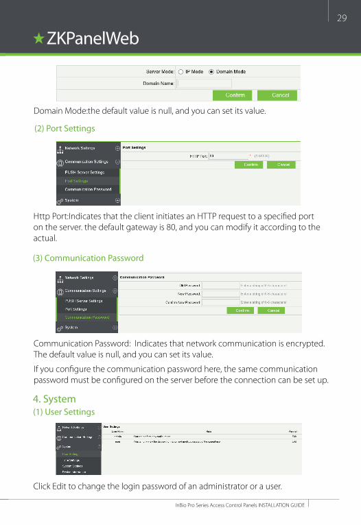
(2) Port Settings
(3) Communication Password
http Port:Indicates that the client initiates an hTTP request to a specifi ed port on the server. the default gateway is 80, and you can modify it according to the actual.
Communication Password: Indicates that network communication is encrypted. The default value is null, and you can set its value.
If you confi gure the communication password here, the same communication password must be confi gured on the server before the connection can be set up.
ZKPanelWeb
4. System(1) User Settings
Click Edit to change the login password of an administrator or a user.
Domain Mode:the default value is null, and you can set its value.

30
InBio Pro Series Access Control Panels INSTALLATION guIDE
(4) Device Information
you can view the basic information, remaining capacity, and network information of the current device.
(3) System Settings
Click Reboot. The device will be restarted.
ZKPanelWeb(2) Time Settings
you can manually confi gure the controller time or synchronize the controller time with the PC time, and click Confi rm to complete the setting..

31
InBio Pro Series Access Control Panels INSTALLATION guIDE
Troubleshooting
1. how to switch four door one way to two door two way? › Connect four readers from reader 1 to reader 4. › Connect two door locks, one connected to LOCK1, another connected to LOCK3. › In the software confi gure reader 1-Indoor, and reader 2-Outdoor.
2. Can we integrate IP Camera and NVR? › Currently ZKBiosecurity software supports ZKTeco’ s IP Cameras and NVR › you can associate a camera to the door and setup a linkage for the same.
3. What does it mean when I get a “Wiegand Format Error”? › your WD0 and WD1 wiring is reversed.
4. how do I connect a third party reader or a stand-alone reader to a InBio Pro panel?
› Connect the wiegand output to the WD0 and WD1 of the stand-alone readers on the panel’s reader port.
Note: The board can only supply 12 V DC, 300mA power so an external power supply may be required.
5. What is the SD card slot used for? › SD card, stores transactions from the panel and creates a back up in additional to internal memory.
6. What kind of wire is recommended for the panel? › 16 or 18 AWg twisted shielded wire is recommended.
7. What is the default IP of the panel? › 192.168.1.201
8. how long is the device under warranty? › 1 year from original purchase date, replacement/repair of hardware under ZK standard warranty requires an evaluation of the failed system by a ZK Technical Support specialist, and the issuance of a Technical Support RMA number.
Figure 34
32
InBio Pro Series Access Control Panels INSTALLATION GUIDE
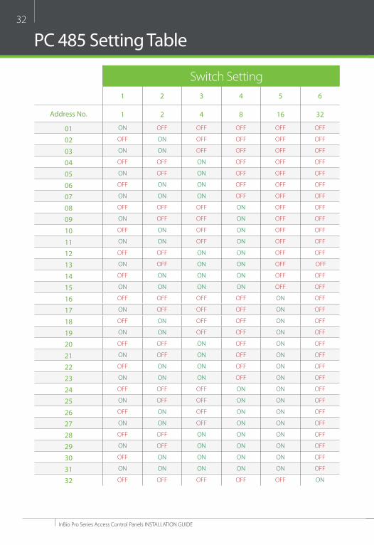
PC 485 Setting Table
Switch Setting1 2 3 4 5 6
Address No. 1 2 4 8 16 32
01 ON OFF OFF OFF OFF OFF
02 OFF ON OFF OFF OFF OFF
03 ON ON OFF OFF OFF OFF
04 OFF OFF ON OFF OFF OFF
05 ON OFF ON OFF OFF OFF
06 OFF ON ON OFF OFF OFF
07 ON ON ON OFF OFF OFF
08 OFF OFF OFF ON OFF OFF
09 ON OFF OFF ON OFF OFF
10 OFF ON OFF ON OFF OFF
11 ON ON OFF ON OFF OFF
12 OFF OFF ON ON OFF OFF
13 ON OFF ON ON OFF OFF
14 OFF ON ON ON OFF OFF
15 ON ON ON ON OFF OFF
16 OFF OFF OFF OFF ON OFF
17 ON OFF OFF OFF ON OFF
18 OFF ON OFF OFF ON OFF
19 ON ON OFF OFF ON OFF
20 OFF OFF ON OFF ON OFF
21 ON OFF ON OFF ON OFF
22 OFF ON ON OFF ON OFF
23 ON ON ON OFF ON OFF
24 OFF OFF OFF ON ON OFF
25 ON OFF OFF ON ON OFF
26 OFF ON OFF ON ON OFF
27 ON ON OFF ON ON OFF
28 OFF OFF ON ON ON OFF
29 ON OFF ON ON ON OFF
30 OFF ON ON ON ON OFF
31 ON ON ON ON ON OFF
32 OFF OFF OFF OFF OFF ON
33
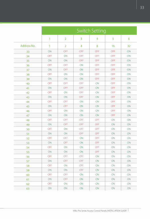
InBio Pro Series Access Control Panels INSTALLATION GUIDE
Switch Setting1 2 3 4 5 6
Address No. 1 2 4 8 16 32
33 ON OFF OFF OFF OFF ON
34 OFF ON OFF OFF OFF ON
35 ON ON OFF OFF OFF ON
36 OFF OFF ON OFF OFF ON
37 ON OFF ON OFF OFF ON
38 OFF ON ON OFF OFF ON
39 ON ON ON OFF OFF ON
40 OFF OFF OFF ON OFF ON
41 ON OFF OFF ON OFF ON
42 OFF ON OFF ON OFF ON
43 ON ON OFF ON OFF ON
44 OFF OFF ON ON OFF ON
45 ON OFF ON ON OFF ON
46 OFF ON ON ON OFF ON
47 ON ON ON ON OFF ON
48 OFF OFF OFF OFF ON ON
49 ON OFF OFF OFF ON ON
50 OFF ON OFF OFF ON ON
51 ON ON OFF OFF ON ON
52 OFF OFF ON OFF ON ON
53 ON OFF ON OFF ON ON
54 OFF ON ON OFF ON ON
55 ON ON ON OFF ON ON
56 OFF OFF OFF ON ON ON
57 ON OFF OFF ON ON ON
58 OFF ON OFF ON ON ON
59 ON ON OFF ON ON ON
60 OFF OFF ON ON ON ON
61 ON OFF ON ON ON ON
62 OFF ON ON ON ON ON
63 ON ON ON ON ON ON

34
InBio Pro Series Access Control Panels INSTALLATION GUIDE
Electrical Specifications
Minim
um
Typical
Maxim
um
Notes
WORKINg POWER SuPPLy
Voltage (V) DC 9.6 12 14.4use regulated DC power adaptor only
Current (A) 2
ELECTRONIC LOCK RELAy OuTPuT
Switching voltage (V) 12Vuse regulated DC power adaptor only
Switching Current (A) 2
Auxiliary relay output
Switching voltage (V) 12Vuse regulated DC power adaptor only
Switching Current (A) 1.25
SWITCh AuX. INPuT
VIh (V)
VIL (V)
Pull- up resistance (Ω) 4.7kThe input ports are pulled up with 4.7k resistors
WIEgAND INPuT
Voltage (V) 10.8 12 13.5
Current (mA) 500
ZK ELECTRIC LOCK
Voltage (V) DC 10.8 12 13.2
Current (mA) 500

35
InBio Pro Series Access Control Panels INSTALLATION GUIDE
Specifications
Communication RS485, TCP/IP
Baud Rate for RS485 9600-15200
Power Supply 12V DC, 3A
Card holders Capacity 30,000
Log Events Capacity 100,000
LED Indicator Indicator for communication, power, status and prox card
Environment 32-113 °F (0-45°C)
Operating humidity 20% to 80%
Number of doors controlled Four Door (four door one way and two door two way)
Number of readers supported 4
Types of readers supported 26- bits WIEgAND, others upon request
Number of Inputs 12 (4 Exit Device, 4 Door Status, 4 AuX)
Number of Outputs 8 (4- Form C relay for lock and 4- Form C relay for Aux output)
Weight 7.8lbs (3.55kg)
Enclosure Metal Cabinet
Mounting Wall Mount
Dimensions (Bundle Only) 15.7in. x 3.56in. x 13.0in 400mm(L) x 90.5mm(W) x 330mm(h)
Dimensions (Board Only) 8.0in. x 4.17in. 203.2mm(L) x 106mm(W)
CPu 32 bit 400Mhz
RAM 32MB
Flash 128MB
Certified

© Copyright 2015. ZKTeco Inc. ZKTeco Logo is a registered trademark of ZKTeco or a related company. All other product and company names mentioned are used foridentification purposes only and may be the trademarks of their respective owners. All specifications are subject to change without notice. All rights reserved.
ZK Building, Wuhe Road, gangtou, Bantian, Buji Town, Longgang District, Shenzhen China 518129Tel:+86 755-89602345Fax:+86 755-89602394www.zkteco.com