Embed Size (px)
Citation preview


[email protected] mailto:[email protected]
your nearest Muncie® distributor or at the number and address below:
need extra, you may order them, no charge, by phone, email or mail. They are available through
The PTO is supplied with a packet containing warning labels. If you did not receive any, or if you
1-800-FOR-PTOS (1-800-367-7867)
Muncie Power Products, Inc.
P.O. Box 548
Muncie, IN 47308--0548
© Muncie Power Products, Inc. 2010
THIS SYMBOL WARNS OF PERSONAL INJURY OR DEATH.
WARNING
ALWAYS READ AND UNDERSTAND THE ENTIRE MANUAL COMPLETELY BEFORE INSTALLATION OR OPERATION OF PTO AND DRIVEN EQUIPMENT INCLUDING THESE WARNINGS AND OPERATOR’S INSTRUCTIONS IN SECTION 3!
ALWAYS DISENGAGE THE PTO WHEN THE DRIVEN EQUIPMENT IS NOT •IN OPERATIONDO NOT ATTEMPT TO INSTALL OR SERVICE ANY POWER TAKE--OFF •WITH THE TRUCK ENGINE RUNNING. PUT IGNITION KEYS IN YOUR POCKET BEFORE GETTING UNDER TRUCK. DO NOT ALLOW TRUCK ENGINE TO BE STARTED WHILE WORKERS •ARE UNDER TRUCK. BEFORE WORKING ON A VEHICLE PLACE TRANSMISSION IN NEUTRAL •OR PARK, SET BRAKES, AND IMMOBILIZE TRUCK WHEELS WITH SUITABLE CHOCKS. BE SURE TO BLOCK ANY RAISED BODY OR MECHANISM BEFORE •WORKING ON OR UNDER EQUIPMENT. INSTALLED POWER TAKE-OFFS MUST NEVER BE SHIFTED IN OR OUT •OF GEAR BY ANY MEANS EXCEPT BY THE CONTROLS IN THE CAB OF THE TRUCK. STAY CLEAR OF SPINNING DRIVESHAFTS TO AVOID BECOMING •ENTANGLED AND INJURED. IT SHALL BE THE RESPONSIBILITY OF THE INSTALLER OF A MUNCIE •POWER TAKE--OFF TO DECIDE WHETHER TO INSTALL GUARDS IN THE PTO AND/OR DRIVELINE AREA BECAUSE OF POTENTIAL EXPOSURE TO DANGER. THIS IS BECAUSE MOST MUNCIE PTOS ARE INSTALLED BY EQUIPMENT DISTRIBUTORS OR MANUFACTURERS AND THEREFORE, THE RESPONSIBILITY OF THE INSTALLATION IS BEYOND THE CONTROL OF MUNCIE POWER PRODUCTS. OBTAIN PROPER TRAINING BEFORE OPERATING THIS MACHINERY•DO NOT INSTALL OR OPERATE EQUIPMENT WHICH HAS NOT BEEN •PROPERLY SPECIFIED FOR YOUR VEHICLEINSTALLERS ARE TO INSURE THAT PTO COMPONENTS DO NOT •INTERFERE WITH ANY CHASSIS COMPONENTS, INCLUDING BUT NOT LIMITED TO VEHICLE CROSSMEMBERS, FRAME RAILS, DRIVESHAFTS, EXHAUSTS, CONVERTERS, FUEL LINES, ETC. WHILE VEHICLE IS STATIONARY OR MOBILE.ALLOW THE VEHICLE, PTO AND DRIVEN EQUPIMENT TO WARM UP •WHEN OPERATING IN WEATHER WHERE TEMPERATURES ARE NEAR OR BELOW FREEZING 32° F (0° C)INSTALL SEPARATE CONTROLS FOR PTO AND DRIVEN EQUIPMENT.•ALWAYS INSTALL THE SAFETY LABELS PROVIDED AND PLACE THE •OWNER’S MANUAL IN THE VEHICLE GLOVE COMPARTMENT.
Page 2
SECTION 3 - TEST PROCEDURE
AUXILIARY WIRING INSTRUCTIONSECTION 2 - WIRE HARNESSES, SCHEMATICS, AND
SECTION 1 - PTO INSTALLATION
..............................................................
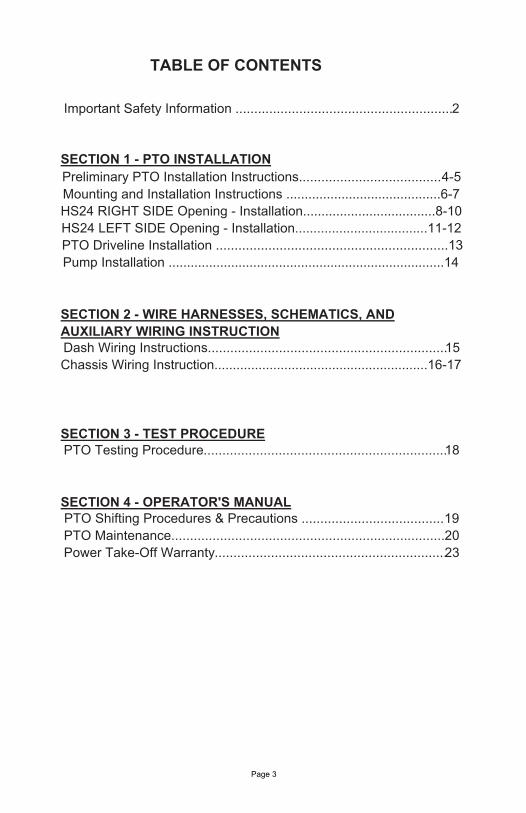
TABLE OF CONTENTS
23
Important Safety Information ..........................................................2
Preliminary PTO Installation Instructions......................................4-5Mounting and Installation Instructions ..........................................6-7HS24 RIGHT SIDE Opening - Installation....................................8-10HS24 LEFT SIDE Opening - Installation....................................11-12PTO Driveline Installation ..............................................................13Pump Installation ...........................................................................14
Dash Wiring Instructions................................................................15Chassis Wiring Instruction..........................................................16-17
PTO Testing Procedure.................................................................18
PTO Shifting Procedures & Precautions ......................................19PTO Maintenance.........................................................................20Power Take-Off Warranty
SECTION 4 - OPERATOR'S MANUAL
Page 3

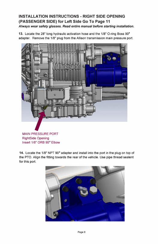
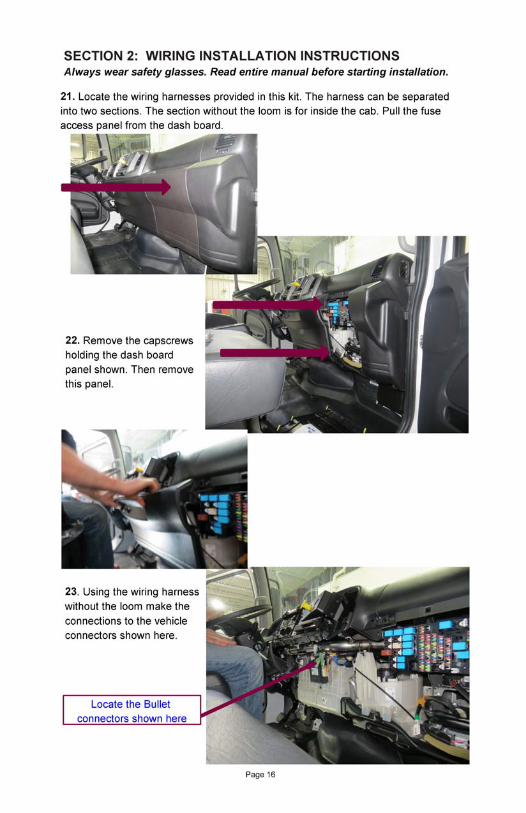
Always wear safety glasses. Read entire manual before starting PTO AND ACTIVATION KIT INSTALLATION INSTRUCTIONS
installation.
READ THE FOLLOWING
SECTION - 1 PTO INSTALLATION
MUSTALL INSTALLERS
IMPORTANT: Disconnect vehicle battery prior to installing electrical and electric/hydraulic activation kits.
Vehicle manufacturers may have specific locations for accessing A.electrical power and activating hydraulics. The body builder manual or company representative for the vehicle chassis should be contacted prior to installing electrical or hydraulic systems. Route wires and activation lines away from rotating and high B.temperature components. Use appropriate looms and bulk head pass-thru’s wherever possible to avoid rubbing through insulation or tubing and causing an electrical short or oil leak. Follow all Federal Motor Vehicle Safety Standards (FMVSS) for C.your vehicle. Where electrical grounds are indicated, be sure that they are D.good grounds, with straight paths to the vehicle battery ground (many vehicle cabs are insulated from the vehicle frame and a weak ground is a very common cause for malfunctions). When installing hydraulic components, be certain to follow E.common installation and testing procedures. If you are not familiar with acceptable installation procedures request instructions and guidance from the hydraulic equipment supplier. Caution should be taken by installer with any PTO installation to F.insure components do not interfere with any chassis component during installation or when vehicle is operated. Cold weather start conditions require that the transmission be G.started and warmed prior to engaging PTO and using equipment. Hydraulic pumps should be run at idle and under no load conditions to allow oil to warm before activating hydraulic system.
Page 4

placed on the outside of the vehicle frame rail. These labels are to be easily seen by
adhering the labels, make sure the surfaces are free of dirt and grease. Place the
anyone who might go under the truck or near the PTO. One label is to be placed on
The two (2) Truck Frame Labels, which measure approximately 4" x 8", are to be
labels supplied with the PTO as follows:
each side of the vehicle. See Figure 1.
INSTALLATION INSTRUCTIONS A
Truck Frame Labels
1. There is a packet with the PTO which contains four (4) warning labels. Before
Note: Should the vehicle body installed on the chassis cover the frame rail, place the label on the
go under the vehicle or near the PTO.
Do NOT paint over the labels.
by anyone who might
installation.
Figure 2
body in a position easily visible
lways wear safety glasses. Read entire manual before starting
Page 5
Figure 1
PTO for Hino Chassis and Allison 3000 Series Transmission.HS24-A10**H**HIncluded with the HS24 PTO with "H" special feature option:48TK5589 Installation Kit.this includes: Mounting Kit, Label Kit, Hose Kit, Activation Kit, andGasket Kit
Visor and Dash LabelsThe PTO Equipped Caution Label, which measures approximately 2” x 3”, is to be placed within the cab of the vehicle and in easy view of the vehicle operator. It should be located near the PTO control, when the control is installed in the vehicle dash (see Figure 2). This label directs the operator to read the PTO operating instructions on the Visor Label. The Visor Label, which measures approximately 4” x 6 ½”, is to be placed on the visor on the operator’s side of the vehicle. See figure 2.


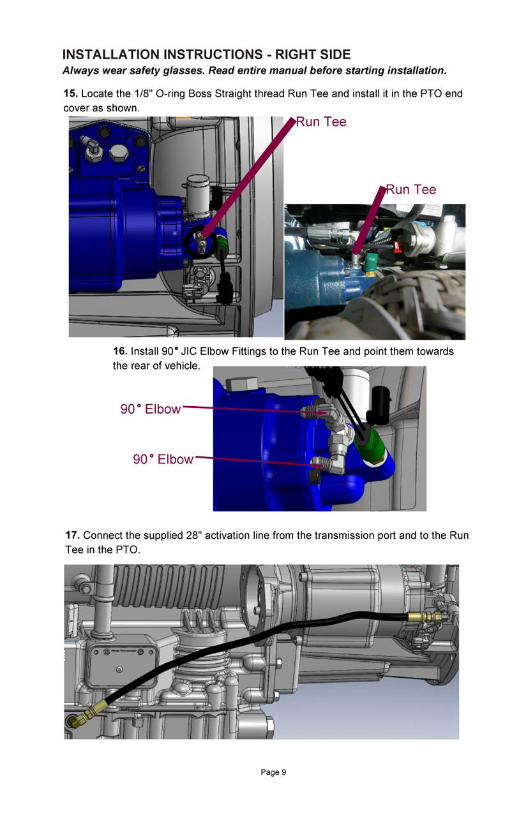
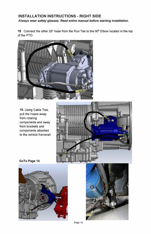


INSTALLATION INSTRUCTIONS A
20.
lways wear safety glasses. Read entire manual before starting installation.
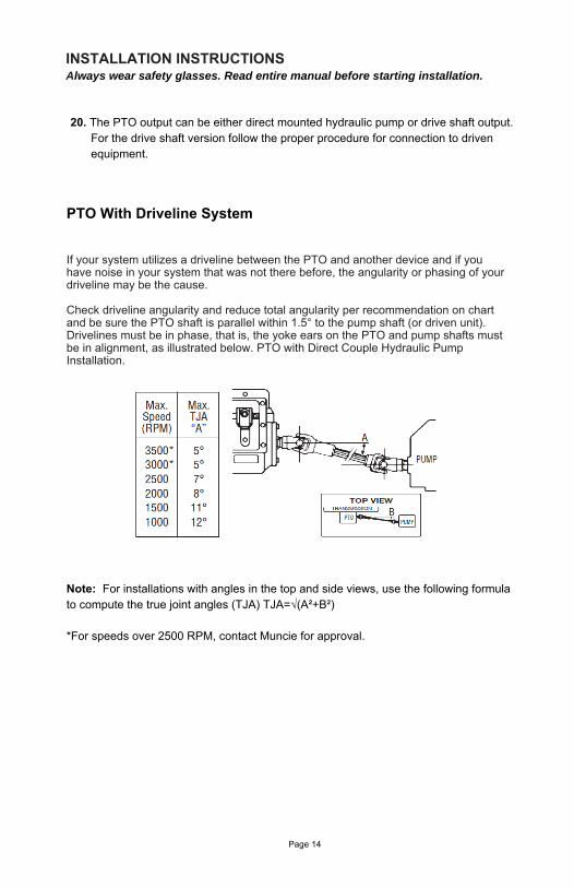
*For speeds over 2500 RPM, contact Muncie for approval.
PTO With Driveline System
equipment.For the drive shaft version follow the proper procedure for connection to driven
The PTO output can be either direct mounted hydraulic pump or drive shaft output.
Note: For installations with angles in the top and side views, use the following formula to compute the true joint angles (TJA) TJA=√(A²+B²)
Page 14
If your system utilizes a driveline between the PTO and another device and if you have noise in your system that was not there before, the angularity or phasing of your driveline may be the cause.
Check driveline angularity and reduce total angularity per recommendation on chart and be sure the PTO shaft is parallel within 1.5° to the pump shaft (or driven unit). Drivelines must be in phase, that is, the yoke ears on the PTO and pump shafts must be in alignment, as illustrated below. PTO with Direct Couple Hydraulic Pump Installation.

Do not force spline couplings together
PTO WITH DIRECT COUPLE HYDRAULIC PUMP
Grease
Grease
Page 15
A bracket attached to two or more transmission bolts and two pump bolts is required. The bracket design should assure that there is no stress or force exerted on the pump or PTO shaft. If the vertical supports are greater than 20° off of perpendicular with the transmission main shaft then a reinforced “Z” bracket must be used. Reinforce horizontal members to prohibit flexing at bend or weld. Attach the bracket at the pump bolt closest to the center of gravity of the pump.
The Muncie direct mount flanges offer multiple mounting bolt holes which allow the flange to be rotated to multiple locations on the PTO for improved port location or clearance. Be sure to torque the capscrew to 25 ft.lb. It is advisable to use a thread locker to secure the cap screws (Loctite 241 or NyLoc or equivalent).
Before bolting the pump to the PTO, place non-seizing compound or grease on the PTO shaft and pump shaft. All Muncie direct mount PTOs are supplied with the appropriate grease. Reusing an existing pump will require inspection of the pump splines. Clean any old grease from pump prior to installation.
Muncie DOES NOT provide a bracket for the PTO. A bracket is required to support single section pumps up to 40# and for multiple section pumps including fittings and oil. An additional bracket must be designed and installed. It should be attached to the rear of the pump and to the transmission to support the pump and to inhibit movement in all directions. *Weight includes fittings, oil and unsupported hose sections.
This requirement does not take into account the system duty cycles, vehicle vibrations, application, terrain, and other external influences. We recommend that direct mounted components of any size or weight be supported when these conditions are extreme or unknown.
This recommendation is based upon our experiences to date. Any failure as a result of damage caused by unsupported weight attached to the PTO will affect any warranty considerations.


28. Refill transmission with manufacturer’s approved fluid and run engine for 5 to 10 minutes to check for leaks, always staying clear of rotating components.
Page 18
INSTALLATION INSTRUCTIONS
SECTION 3 - TEST PROCEDUREStart engine and with engine at idle or output shaft speed under 1200 RPM engage PTO. If PTO fails to operate or will not develop enough torque to operate your equipment, check pressures as follows:
a. Stop engine.
b. Install 400 PSI pressure gauge at the pressure inlet of PTO and a 400 PSI gauge at the pressure switch port.
c. Start engine. Stay clear of rotating components. Check gauge at inlet to PTO. If gauge registers less than 150 PSI, check for obstructions in the hoses and verify that activation hose is connected to the correct port on the transmission.Recheck the transmission information for the main pressure tap location on your model transmission. If plumbing is correct then transmission should be inspected at an authorized Allison/Caterpillar service center or dealer.
d. Place PTO switch in engage position. Stay clear of rotating components. If either gauge registers less than 150 PSI or if there is more than 50 PSI difference in the readings, then turn off engine and remove the solenoid valve and check the solenoid orifices, fittings and hoses for contamination.
e. If these suggestions do not improve the operation of the PTO then a catastrophic failure may have occurred and the PTO should be inspected at a Muncie service center.
After complete installation, installers need to check for leaks and proper mounting-torque of fasteners. Operate the equipment for an appropriate amount of time to establish for proper operation or per the equipment manufacturer’s recommendation. After shutting down equipment and engine, check for leaks. Allow unit to sit for 60 minutes, then check again for any leaks. Fix all leaks per manufacturer’s recommendation.
29. Complete installation by placing warning labels as indicated on borders of the decals. Placement examples are illustrated on page 5; turn to Section 4 of Owner’s Manual.
Power Take-Off Operation - Vehicle Stationary
WARNING -
WARNING - ’
WARNING -
WARNING - ’ whenever the engine is running and the transmission
is in gear, in order to prevent or stop any unexpected movement of the vehicle which may cause
injuries to the operator or others in the vicinity.
Read all operators manuals and instructions for the equipment that you are operating on this vehicle. •
Obtain instructions and training for all operations of the equipment on this vehicle including those not covered •
by this instruction booklet.
Never work alone when repairing or going under a vehicle for repair or maintenance.•
Always block any raised or moveable components or devices when working on or around the vehicle as •
specified by the equipment manufacturer.
Warning: PTOs may drive driven equipment with an exposed drive shaft which may cause severe injury or •
death if contacted.
Care must be taken when using a PTO for any specific application that the PTO has been properly specified •
to match the transmission and auxiliary equipment. Improper specification and installation can cause severe
damage to the vehicle transmission and the auxiliary components including driveshafts a .
D , resulting in failure can cause serious personal injury to operators and
persons in the vicinity.
Always follow recommended procedures for selecting, , , •
M ’ , , , .
N M PTO speed of the unit or the specified driven unit. •
Never use a power take off that has not been specified for the output capabilities for the equipment •
being driven.
Rotating PTO drive shaftsIt is recommended that direct couple hydraulic pumps be used whenever possible, but if your application requires
the use of an exposed drive shaft it is the responsibility of the installer and purchaser to determine the best
installation of a guard.
R , , , , . cause serious injury or death.•
Do not go under the vehicle when the engine is running.•
Do not work near an exposed drive shaft with engine running.•
Auxiliary shaft can be installed with recessed or protruding . I and •
, then be aware that this is a catch point for clothes, skin, , , . j
.
T PTO PTO .
PTO rotation can cause sudden movement of the output shaft and attached drive shaft leading to personal
injury or death. Allow transmission to operate for a few minutes before engaging PTO. Allow PTO to operate for a
few minutes before actuating application controls.
Some O.E.M. chassis manufacturers have integrated electronic controls which require certain conditions to be met
before PTO. T , , ,
, accelerator pedal, and/or transmission selector in park or neutral.
PTO Shifting Procedure & PrecautionsINSTRUCTIONS SECTION 4 - OPERATOR’S
WARNING
THIS SYMBOL WARNS OF PERSONAL INJURY OR DEATH
parking brake must always be set
vehicle s wheels must always be chocked
transmission must always be in neutral or park
an operator must always be in the driver s seat
nd driven equipment
amaged components equipment
installing operating or repairing a power take off as
found in uncie owner s manuals service parts lists and service manuals catalogs and application guides
ever use a uncie above the recommended operating
otating shaft can snag clothing skin hands hair etc and will
set screws f raised square head set screws
are chosen hair hands etc and serious in ury or
death may result
he output shaft of a with internal clutch packs may rotate in cold temperatures with the disengaged
shaft
engaging a hese include but are not limited to setting parking brake foot off service brake engine at
idle foot off
Page 19
PTO Maintenance
Page 20
The Power Take-Off, being an integral part of the transmission, should be serviced at the same intervals as the transmission. Transmission fluid changes should follow the interval recommended by the vehicle manufacturer for severe service. Transmission oil level is important. Checking for PTO leaks and checking the transmission oil level should be done on a regular basis. Check for leaks upon delivery of the vehicle and after initial operation of your equipment. Loss of any oil can significantly affect or damage a transmission or PTO. Muncie Power Products, Inc. is not responsible for damage resulting from improper fastener installation, mounting torque or maintenance of the PTO.
The Power Take-Off is also part of a system. The PTO system may include the activa-tion control parts, a driveshaft, or hydraulic pump. This PTO system requires periodic checks and service. Typically the interval for maintenance checks of the PTO system depends on the application of the system. Every time the chassis is lubricated or a mechanic is under the vehicle the PTO system should be checked and serviced. For severe duty PTO system applications, it is recommended that the system be checked for service every 100 hours of use (this guideline can be adjusted based on past service history once you have it established). Service should include checking and lubricating direct mount pump shaft connections. PTO gears can be checked for wear by removing the inspection or shifter cover. If pitting, galling, cracking, or deformation of the gears or splines has occurred, then the PTO needs to be rebuilt or replaced.
Within the first week of use, recheck the installation of the PTO. Check for leaks and loose mounting hardware (studs, cap screws, nuts). Recheck the cable or lever connections for proper adjustment and tighten any loose connections. At regular maintenance intervals, check adjustments and lubricate moving parts, tighten and repair the connections, mounting hardware, cable or lever linkages.
It is recommended that the operator/owner do a visual inspection for leaks under and around the vehicle and equipment on at least a weekly basis. Any leaks found should be corrected immediately.
Pumps that are mounted directly to the PTO output require the application of an anti-seize or a high temperature, high pressure grease (Muncie PTOs are initially supplied with the required grease). The purpose of this grease is to help make the PTO easier to service and to reduce the effects of fretting corrosion on the mating PTO and pump shafts. PTO applications under severe duty cycles and/or high torque requirements may require servicing this shaft connection by periodically regreasing the shafts. Vehicles with low speed diesel engines are also severe applications due to the vibrations inherent in these vehicles. Fretting corrosion cannot be stopped by applying grease; the grease is only a deterrent.

Page 21
NOTES:

Page 22
NOTES:

The Muncie Power Take-Off is warranted to be free of defects in material or workmanship and to meet Muncie’s standard written specifications at the time of sale. Muncie’s obligation and liability under this warranty is expressly limited to repairing or replacing, at Muncie’s option, within one year after date of original installation any defective part or parts or any product not meeting the specifications.
THIS WARRANTY IS IN LIEU OF ALL OTHER WARRANTIES, EXPRESSED OR IMPLIED. MUNCIE MAKES NO WARRANTY OF MERCHANTABILITY OR OF FITNESS FOR ANY PARTICULAR PURPOSE. MUNCIE’S OBLIGATION UNDER THIS WARRANTY SHALL NOT INCLUDE ANY TRANSPORTATION CHARGES OR COSTS OF INSTALLATION OR ANY LIABILITY FOR DIRECT, INDIRECT SPECIAL, INCIDENTAL, OR CONSEQUENTIAL DAMAGES OR DELAY. THE REMEDIES SET FORTH HEREIN ARE EXCLUSIVE, AND MUNCIE’S LIABILITY WITH RESPECT TO ANY CONTRACT OR SALE OR ANYTHING DONE IN CONNECTION THEREWITH, WHETHER IN CONTRACT, IN TORT, UNDER ANY WARRANTY, OR OTHERWISE, SHALL NOT, EXCEPT AS EXPRESSLY PROVIDED HEREIN, EXCEED THE PRICE OF THE PRODUCT OR PART ON WHICH SUCH LIABILITY IS BASED.
If requested by Muncie, products or parts for which a warranty claim is made are to be returned transportation prepaid to a Muncie Service Center. Any installation or use not in accordance with catalogue or package instructions, other improper use, operation beyond capacity, substitution of parts not approved by Muncie, use with equipment other than the equipment on which the Power Take-Off is first installed, or alteration or repair made to the Power Take-Off other than at a Muncie Service Center shall void this warranty. No employee or representative of Muncie is authorized to change this warranty in any way or to grant any other warranty.
Page 23
Power Take-Off Warranty