Embed Size (px)
Citation preview
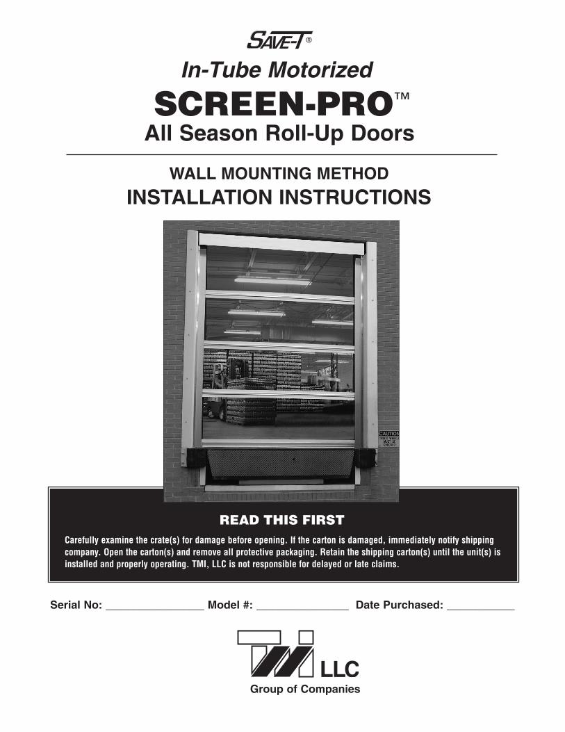
SCREEN-PRO™
WALL MOUNTING METHOD
INSTALLATION INSTRUCTIONS
All Season Roll-Up Doors
In-Tube Motorized
Carefully examine the crate(s) for damage before opening. If the carton is damaged, immediately notify shippingcompany. Open the carton(s) and remove all protective packaging. Retain the shipping carton(s) until the unit(s) isinstalled and properly operating. TMI, LLC is not responsible for delayed or late claims.
READ THIS FIRST
Group of Companies
Serial No: ________________ Model #: _______________ Date Purchased: ___________

Screen Material withModular Panels
(Attached to Roller Drum)
GuideTracks
Top SpreaderAngle
Brush SealBrush Seal
Bar
Screen Roller Drum
Top SpreaderMounting Bracket
BracketAnchor Angles
BracketAnchor Plates
FlangedNuts
FloorAnchorAngle
Drum MountingPlate
(Motor Side)
Drum MountingPlate
(Bearing Side)
SCREEN-PRO COMPONENTS
It is recommended that two peopleinstall the door together.
The following tools will be neededfor installation:
• Carpenter’s Level (Min. 4’ Length)
• Carpenter’s Square
• Hammer Drill
• Masonry Drill Bit (For 3/ 8” Diameter Anchors)
• 3/ 8” Diameter and Various Wall Anchors
• Assorted Shim Stock
• Socket and Wrench Set
• Hand Tools
• Four Bar Clamps (36” Long)
• Two Ladders
• Forklift (Supplied by Dealer or Customer)
REQUIRED TOOLS
2
TYPES OF DOORS
There are a variety of doors used at both industrial andcommercial facilities. Each has its specific opening/closingmechanism. This Screen-Pro unit has been shipped withhardware to accommodate a Wall Mounting Method. TheGuide Tracks should be mounted flush against the wall.
PLAINDOORWAYOPENING
OVERHEADDOOR
ROLL-UPDOOR
Read and Save These Instructions
To Reduce the Risk of Fire, Electrical Shock, or Injury, Observe the Following:Warning
• Use this unit only in the manner intended by the manufacturer. If you have any questions, contact the manufacturer.• Installation work must be done by a qualified person(s) in accordance with all applicable codes and standards.• When cutting or drilling into wall or ceiling, do not damage electrical wiring and other hidden utilities.• All electrical work should be performed in accordance with local and state building codes. If you are in doubt of proper
wiring installation, we recommend acquiring the services of a certified electrician.
Please read the “READ THIS FIRST” note on the front cover of this manual before proceeding.
IMPORTANT NOTEIf the Screen-Pro was ordered with optional electrical components and accessories (door switch, control panels,mounting brackets, etc), the accessories may be found in an additional box. Check all of the boxes before disposing

STEP 1
STEP 2
Lay the basic components in front of the doorway opening. Usingwork horses will make the assembly process easier although it isnot essential.
BrushSeal
RightGuide Track
Brush SealBar
Slide the Brush Seal into the edge groove of the Brush Seal Bar.
STEP 3
Place the Guide Tracks on the horses with theGuide Flare Plate facing up.
NOTE: There is a left anda right Guide Track.
IMPORTANTThe Guide Track Flare Plate ships flat and must be bent out
11/2” before any assembling takes place.
3
LeftGuideTrack
Bracket Anchor Plates(3 to a side for 10’x10’ doors or smaller)
Slide the Bracket AnchorPlates into the guide channelthat is on the outside edge ofthe Track Guides. There are6 Anchor Plates, 3 for eachside on a 10' high door.

4
Place a Bracket Anchor Angle oneach Bracket Anchor Plate. The topAngle should be 8'' down from thetop of the Guide Track The bottomAngle should be 1/4'' from the bottomof the Track. Also, place the FloorAnchor Angle on the bottom BracketAnchor Plate. The remaining twoAngles should be evenly placedbetween the top and bottom Angles.
Place a Flange Nut on each AnchorPlate and hand tighten. Use a squareto make sure that each Anchor Angleis perpendicular to the Guide Trackand flush with the Wall Edge. Also,the bottom of the Floor Anchor Angleis flush with the bottom of the Track.Finally tighten each Flange Nut witha wrench.
TOP BOTTOM
LEFT SIDE
TOP
4''1/4''
BracketAnchor Angle
BracketAnchor Angle
BracketAnchor Angle
BracketAnchorAngle
BracketAnchor Angle
Square Bracketsto Guide Track
FloorAnchor Angle
FloorAnchor Angle
FlangeNut
FlangeNut
FlangeNut
FlangeNut
Guide Track
Wall Edge
Wall Edge of Guide Track
STEP 4
STEP 5
NOTE: The oval hole on each Angleshould go over the threaded stud.
Guide TrackTop Spreader
BracketAnglefacingdown
SpreaderMountingBracket
2'' BrushSeal Bar
Brush Bristlesshould face down
Self-TappingSheet Metal
Screws
Attach the Top Spreader Bracket to the top ofthe Guide Track using the Spreader MountingBracket. Make sure the back of the SpreaderAngle is facing down and toward the wall.
Use 2 bolts and flange nuts on each side tosecure all the components.
Place the 2'' Brush Seal Bar on top of the SpreaderBracket and center it. The brush bristles should befacing in and down. Mark each mounting hole on theSpreader Bracket. Remove the bar and drill smallholes.
Replace the bar and secure it with Self-TappingSheet Metal Screws.

5
STEP 7
Attach the Drum MountingPlates to the top of each TrackGuide using 5/16'' x 1-1/4''bolts with flange nuts. The “C”Bracket (motor side) goes onthe left and the round cradle(bearing side) is on the right.
IMPORTANT: Use the bottomhole of each set of holes.
Bottom Hole(Set 1)
Bottom Hole(Set 2)
Drum MountingPlate with“C” Braket
(Motor Side)
Drum Mounting Plate(Bearing Side)
Using a helper, swing the assembly into place andcenter it on the doorway opening. The bottom ofthe Guide Tracks should be on the floor and theBracket Anchor Angles should be flush against thewall. Make sure that each Guide Track is plumb.Mark each of the holes including the Floor AnchorBrackets.
Remove the assembly and drill the holes. If the wallis concrete or cement block, a wall anchor will benecessary.
Then replace the assembly and secure it to thewall using lag screws.
STEP 6
WARNINGDO NOT remove the Roll Ties until the Roll Tube
is secured to both Drum Mounting Plates.
Bushing/Bearing
Screen onRoller Drum
In-TubeMotor
Roll Ties
STEP 8
Place the Screen Roller Drum into each Drum Mounting Plate.The In-Tube Motor should be to the left and the Bearing to theright. Also the Bottom Edge of the Screen should be facingdown. NOTE: In-Tube Motor comes standard on left side, unlessordered for right side.
DrumMounting
Plates
Bottom Edgeof Screen
facing down

6
STEP 9
Then carefully cut the Roll Ties without cutting the screen.Slip the bottom edge of the screen into the Guide Tracks.Place the leading edge in front of the Rubber Gasket tocreate a seal.
Bottom Edgeof Screen
RubberGasket
STEP 10
At this point the Screen Roller Drum must be leveled. The Drum Bracket Mounting Boltson one or both sides can be loosened and the drum can be accurately leveled.
RoundCradle
Bolt /Nutin top hole
On the right side, place a bolt with anut through the Top Mounting PlateHole to secure it to the Cradle.
“C” Bracket
Pin Clip
NylonBushing
MotorHead
With the LimitAdjustment Screwsfacing outward,place the nylonbushing over thebottom pin.
Insert theMotor Headinto the“C” Bracket.
Place the Pin Clipunder the Bracket Lipand around the top pin.
LimitAdjustmentScrews

7
STEP 11
Next, the motor should be connected to a120 v, 60hz power source. The location of theUp/ Down Switch is up to the installer but itshould be convenient for the operator. Followthe wiring diagram to the right.
RED
BLACK
Direction 1
Direction 2
WHITE
GREEN
Neutral
Ground
WHITENeutral
GREENGround
BLACK
120v - 60hz
IMPORTANT
All electrical work should be performed inaccordance with local and state buildingcodes. If you are in doubt of proper wiringinstallation, we recommend acquiring theservices of a certified electrician.
From theWall
Up/Down Switch
Motor
STEP 16 – NOTE –
Some models have themotor on the right but thelimit adjustment screwconfiguration and graphicsare the same as the morecommon left motor positioning.
Down LimitAdjustment Screw
Up LimitAdjustment Screw
Set the up limit and the down limit. Use the suppliedBlack Plastic Tool to set the limits.
Note: The screw on top sets the “Down/Lower” limit.The switch on the bottom sets the “Up/Top” limit.Material should roll off the back side of barreltowards the wall.
Important: The large arrows on the far left of thedrum by the limit adjustment screws refer to thedrum rotation.
A. It is important to note that the arrows by the limit adjustment screw refer to thedrum rotation. The door panel comes off the tube on the back side and thelimit adjustment faces the front of the door assembly.
B. Turning an adjustment screw clockwise will increase the maximum travel inthe direction that it controls, and turning it counterclockwise will decrease themaximum travel.
C. To set a limit, run the motor in the selected direction.
D. If the motor stops on its own before reaching the desired stop, turn the appropriate limit screw positive (clockwise). Every 3-4 turns of the limit adjustment screw equals approximately 1” of screen travel. Afterturning the limit adjustment screw, use the control switch to move the motor to the new limit position. NOTE: If the motor does not stop on its own before reaching the desired limit, go to Step F.
E. When you are approximately at the desired limit position, use the control switch to run the motor away fromthe limit, 2’ to 3’ and then back.This will allow you to see precisely where the limits are set. Make smalladjustments if required.
F. If the motor does not stop on its own at least 6” before the desired limit position, stop the motor with thecontrol switch. Then turn the adjustment screw counterclockwise (negative) direction. Confirm that themotor is at the limit and set the limit as per Steps D & E. If the motor has not stopped at the limit, continueturning the screw counterclockwise (up to 120 turns may be needed).
NOTE: The motor has a built in thermal cut-off. If after several minutes of use the motor will not run in eitherdirection, allow the motor to cool for approximately 20 minutes before using again.

800-888-9750TMI, LLC • 5350 Campbells Run Road • Pittsburgh, PA 15205-9738 • 412.787.9750
Fax: 412.787.3665 • Web Site: www.tmi-pvc.com • E-Mail: [email protected] © 2011 TMI, LLC Catalog No. II-TMI-SP-RUD-W-M 08-11
NOTES


![Supreme 2 In-Ceiling Motorized Screens Slot Opening · Motorized Screens In-Ceiling Supreme 2 In-Ceiling Motorized Screens Slot Opening [1] Technical Product Information Screen Fabric](https://img.dokumen.tips/doc/110x75/5b7719517f8b9a47518c4686/supreme-2-in-ceiling-motorized-screens-slot-motorized-screens-in-ceiling-supreme.jpg)