Embed Size (px)
Citation preview

DOE-FIU SCIENCE & TECHNOLOGY WORKFORCE DEVELOPMENT PROGRAM
STUDENT SUMMER INTERNSHIP TECHNICAL REPORT April 26, 2010 to July 2, 2010
In Situ Remediation and Stabilization Technologies for Mercury in Clay Soils
Principal Investigators:
Elsa Cabrejo (DOE Fellow) Florida International University
Elizabeth Phillips, Mentor
DOE EM Oak Ridge Office
Acknowledgements:
Dr. Paul Kalb, Brookhaven National Laboratory Dr. Zhong Xiong, Ph.D., P.E., AMEC Geomatrix, Inc.
Dr. Fengxiang Han, Ph.D, Mississippi State University
Florida International University Collaborator and Program Director:
Leonel Lagos Ph.D., PMP®
Prepared for:
U.S. Department of Energy Office of Environmental Management
Office of Science and Technology Under Grant No. DE-FG01-05EW07033

DISCLAIMER This report was prepared as an account of work sponsored by an agency of the United States government. Neither the United States government nor any agency thereof, nor any of their employees, nor any of its contractors, subcontractors, nor their employees makes any warranty, express or implied, or assumes any legal liability or responsibility for the accuracy, completeness, or usefulness of any information, apparatus, product, or process disclosed, or represents that its use would not infringe upon privately owned rights. Reference herein to any specific commercial product, process, or service by trade name, trademark, manufacturer, or otherwise does not necessarily constitute or imply its endorsement, recommendation, or favoring by the United States government or any other agency thereof. The views and opinions of authors expressed herein do not necessarily state or reflect those of the United States government or any agency thereof.

ARC-2007-D2540-032-04 In Situ Remediation and Stabilization Technologies for Mercury in Clay Soils
iii
ABSTRACT
The present study includes innovative in situ remediation technologies for the treatment and/or stabilization of mercury contaminated soils. It presents four green alternatives for the treatment of mercury in clay soils, with the common advantages of low energy requirements, low cost, no excavation, no addition of harmful chemicals, and minimal exposure of workers and the general public to the contaminant while performing the remediation/stabilization operations.
The stabilization technologies use the affinity of elemental mercury for elemental sulfur to promote a reaction that produces mercury sulfide, which is a form of mercury characterized by being highly stable in the environment and insoluble in water.

ARC-2007-D2540-032-04 In Situ Remediation and Stabilization Technologies for Mercury in Clay Soils
iv
TABLE OF CONTENTS
LIST OF FIGURES ........................................................................................................................ v
ACRONYMS ................................................................................................................................. vi
EXECUTIVE SUMMARY ............................................................................................................ 1
1. BACKGROUND ........................................................................................................................ 2
1.1 Introduction ........................................................................................................................... 2 1.2 Objectives .............................................................................................................................. 2 1.3 Site Characteristics ................................................................................................................ 2
1.3.1 Geology .......................................................................................................................... 3 1.3.2 Mercury Contamination in the Y-12 Area ...................................................................... 4
1.4 Characteristics of Clay Soils ................................................................................................. 6 1.5 Treatment Goals .................................................................................................................... 6
2. TRANSPORT MECHANISMS OF MERCURY IN SOIL........................................................ 7
3. IN SITU REMEDIATION TECHNOLOGIES .......................................................................... 9
3.1 Electro Chemical Remediation Technologies Induced Complexation (ECRTs-IC) ............. 9 3.1.1 Description of the Technology ....................................................................................... 9 3.1.2 Advantages and Disadvantages to ECRTs-IC .............................................................. 11 3.1.3 Case Studies Using ECRTs-IC ..................................................................................... 11
3.2 In Situ Mercury Stabilization (ISMS) ................................................................................. 12 3.2.1 Description of the Technology ..................................................................................... 12 3.2.2 Mercury Stabilization Using Sulfur Polymer Stabilization/Solidification ................... 13 3.2.3 Advantages and Disadvantages of ISMS ...................................................................... 13
3.3 Nanotechnology .................................................................................................................. 14 3.3.1 Description of the Technology ..................................................................................... 14 3.3.2 Advantages and Disadvantages of Nanotechnology .................................................... 15
3.4 Phytoremediation ................................................................................................................ 15 3.4.1 Description of the Technology ..................................................................................... 16 3.4.2 Advantages and Disadvantages of Phytoremediation .................................................. 17
4. CONCLUSIONS AND RECOMMENDATIONS ................................................................... 18
5. REFERENCES ......................................................................................................................... 19
Appendix A ................................................................................................................................... 22
Appendix B ................................................................................................................................... 23
Appendix C ................................................................................................................................... 24
Appendix D ................................................................................................................................... 25

ARC-2007-D2540-032-04 In Situ Remediation and Stabilization Technologies for Mercury in Clay Soils
v
LIST OF FIGURES
Figure 1. Contaminant Transport at the Y-12 area (ATSDR, 2006, p. 30) .................................... 3 Figure 2. Oak Ridge Reservation Geology Map. Source (ATSDR, 2006, p. B2) .......................... 4 Figure 3. Mercury use areas and mercury concentrations at Y-12 (DOE, 2002, pp. 2-17) ............ 5 Figure 4. Conceptual Model for Mercury in Soil, Groundwater and Streams (DOE, 2008b) ........ 7 Figure 5. ECRTs Pore Scale Redox Modela ................................................................................. 10 Figure 6. ECRTs test cell (Burks, 2002) ....................................................................................... 12 Figure 7. Schematic of ECRTs-IC test cell ................................................................................... 12

ARC-2007-D2540-032-04 In Situ Remediation and Stabilization Technologies for Mercury in Clay Soils
vi
ACRONYMS
CERCLA Comprehensive Environmental Response, Compensation, and Liability Act
DC Direct Current
DOC Dissolved Organic Carbon
DOE-EM Department of Energy – Environmental Management
ECRTs-IC Electro-Chemical Remediation Technologies, Induced Complexation
EFPC East Fork Poplar Creek
EPA Environmental Protection Agency
ETTP East Tennessee Technology Park
ISMS In Situ Mercury Stabilization
LDR Land disposal restrictions
nZVI Nano Scaled Zero-Valent Iron
ORNL Oak Ridge National Laboratory
ORR Oak Ridge Reservation
PCBs Polychlorinated Biphenyls
SPC Sulfur Polymer Cement
SPSS Sulfur Polymer Stabilization/Solidification
TCE Trichloroethylene
UEFPC Upper East Fork Poplar Creek
VOCs Volatile Organic Compounds
WEMA West End Mercury Area

ARC-2007-D2540-032-04 In Situ Remediation and Stabilization Technologies for Mercury in Clay Soils
1
EXECUTIVE SUMMARY
This report includes in situ remediation technologies for mercury contaminated soils, with specific applicability to clay type soil characteristic of the Oak Ridge Reservation (ORR), where mercury is a contaminant of concern specifically at the Y-12 National Security Complex (Y-12).
The ORR is an area of about 14,260 ha located in the state of Tennessee, where the Conasauga group is the main geological unit underlying the Y-12 complex. This formation is where most of the radionuclides and waste materials have been deposited and is composed mainly of clays and quartz minerals with variable amounts of carbonate bedrock. The soils from the Conasauga group have low permeability (1X10⁻⁵ cm/sec), hydraulic conductivity in the order of 3.54X10⁻⁴ cm/s, pH around 4.7, and great affinity to absorb radionuclides.
Mercury contamination originated from discharges of waste water into the East Fork Poplar Creek (EFPC), percolation of acidic wastes, seasonal inundation, and movement of groundwater through contaminated bedrock (DOE, 1998). The higher levels of mercury are expected in the areas of the former mercury use buildings which includes the West End Mercury Area (WEMA) and Building 81-10. Revis et al. (1989) concluded that of the total mercury found, between 0.003 and 0.01% was organic mercury, an average of 92% was mercuric sulfide, and about 6% was elemental mercury.
The present study includes four in situ remediation technologies that were selected with the perspective of presenting a green remediation approach that removes or stabilizes mercury into mercury sulfide. Low energy use, no addition of harmful chemicals, and low overall expected cost for the implementation were the most important parameters in defining the technologies for the study and, therefore, the recommendation for a pilot scale field test.
Appendix C presents a comparative table with brief descriptions, advantages and disadvantages of the studied approaches: electrochemical remediation, in situ mercury stabilization, nanotechnology, and phytoextraction.
Appendix D includes contact information for the inventors of three of the technologies whose contribution to this report was invaluable.

ARC-2007-D2540-032-04 In Situ Remediation and Stabilization Technologies for Mercury in Clay Soils
2
1. BACKGROUND
1.1 Introduction For more than four decades, radioactive and nonradioactive wastes were generated at the Oak Ridge Reservation (ORR) as a result of the development and production of nuclear weapons during the Cold War era. Several contaminants were released into the environment, including polychlorinated biphenyls (PCBs), carbon tetrachloride, uranium, nitrate, technicium-99 (99Tc), other radionuclides, and mercury.
In situ remediation technologies have become an increasingly important consideration for DOE sites, where large volumes of soil have contaminants over established limits. An effective way to start the remediation effort is to understand the properties and characteristics of targeted soils; in the case of the ORR, geological formations underlying the area are mainly composed of clay minerals, with low permeability and high adsorption capacity, which present special challenges in the selection of an appropriate remediation approach.
This analysis focuses on innovative green technologies that can be used for in situ remediation of mercury-contaminated clay soils as an alternative to the current “dig and haul” methods. Four innovative technologies are introduced: electrochemical remediation, in situ mercury stabilization, nanotechnology, and phytoextraction, along with recommendations for further development as pilot scale studies at the site.
1.2 Objectives Past remediation efforts for soils have included the excavation and removal of contaminated soils, followed by refill with new soil. This study presents innovative technologies for the in situ remediation of mercury contaminated soils, with specific application to the clay soils that characterize the Oak Ridge Reservation area.
The main objectives for this study are to present new low energy consuming, green technologies that minimize costs and the disturbance of the environment, and that can be further investigated in a bench scale scenario under site specific conditions.
Another important objective is to reveal new developments that can be used as an initial plan in the establishment of the new mercury engineering and technology demonstration center, under the supervision of the DOE Environmental Management office at Oak Ridge, TN.
1.3 Site Characteristics The Oak Ridge Reservation (ORR) is located in the Tennessee counties of Anderson and Roane, on the west side of the Valley and Ridge Trust Belt, and encompasses an area of about 14,260 ha. The reservation has three major facilities: the Y-12 National Security Complex (Y12), East Tennessee Technology Park (ETTP), and Oak Ridge National Laboratory (ORNL). The Y12 complex is located in the Upper East Fork Poplar Creek and Bear Creek watersheds, with mercury, volatile organic compounds (VOCs), nitrate, uranium and manganese as the principal contaminants of concern ( Figure 1).
ARC-2007-D2540-032-04 In Situ Remediation and Stabilization Technologies for Mercury in Clay Soils
3
Figure 1. Contaminant Transport at the Y-12 area (ATSDR, 2006, p. 30)
ORNL, located within Bethel Valley and Melton Valley Watersheds, was originally known as the X-10 site. It was built in 1943 for pilot programs related to plutonium production and chemical separation of nuclear products. The main contaminants of concern at this site include radiological wastes, strontium 90 (90Sr), tritium (3H), cesium 137 (137Cs), and uranium 233 (ATSDR, 2006, pp. 16-21).
The ETTP or K-25 site is located along Poplar Creek. Liquid thermal diffusion and gaseous diffusion processes were the main historical activities in the plant. Among the contaminants present in soils are semi-volatile organic compounds (S-VOCs), polyaromatic hydrocarbons (PAHs), VOCs, and inorganic elements (ATSDR, 2006, pp. 7-8).
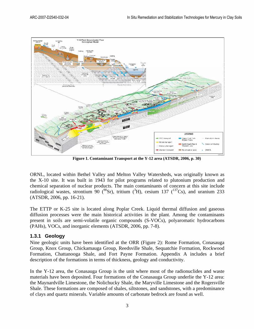
1.3.1 Geology Nine geologic units have been identified at the ORR (Figure 2): Rome Formation, Conasauga Group, Knox Group, Chickamauga Group, Reedsville Shale, Sequatchie Formation, Rockwood Formation, Chattanooga Shale, and Fort Payne Formation. Appendix A includes a brief description of the formations in terms of thickness, geology and conductivity.
In the Y-12 area, the Conasauga Group is the unit where most of the radionuclides and waste materials have been deposited. Four formations of the Conasauga Group underlie the Y-12 area: the Maynardville Limestone, the Nolichucky Shale, the Maryville Limestone and the Rogersville Shale. These formations are composed of shales, siltstones, and sandstones, with a predominance of clays and quartz minerals. Variable amounts of carbonate bedrock are found as well.
ARC-2007-D2540-032-04 In Situ Remediation and Stabilization Technologies for Mercury in Clay Soils
4
Figure 2. Oak Ridge Reservation Geology Map. Source (ATSDR, 2006, p. B2)
Soils from the Conasauga Group have low permeability and an affinity to absorb radionuclides due to the presence of clay (DOE, 1993, p. 14). A geometric media of the hydraulic conductivity of the fractured and bedded rocks in the Y-12 area was calculated as 3.54X10⁻⁴ cm/s. Permeability at the site is assumed to be in the order of 1X10⁻⁵ cm/sec and depth to the water table about 8 ft (Rothchild, 1984, p. 39). Soil profile descriptions from core samples collected at different locations within the ORR during the background soil characterization project showed soil pH to be around 4.7 (DOE, 1993, pp. 129-139).
When studying the geology and characteristics of the soils that form the Y-12 area, it is important to consider the alteration of the original topography of the UEFPC Watershed that took place during the construction of the Y-12 plant. Tributaries and a portion of the west and central main channel were converted into subsurface drains and then covered with filling materials with thicknesses up to 30 ft.
1.3.2 Mercury Contamination in the Y-12 Area Different pathways have been identified through the years for the introduction of the mercury in the soil: 1) discharges of waste water from the Y-12 facility into the East Fork Poplar Creek (EFPC), followed by flooding events that contaminated the floodplain; 2) percolation of acidic wastes, from spills and leaks, into the subsurface; 3) seasonal inundation of sludge left at the sites after closing processes; and 4) the movement of groundwater through contaminated bedrock (DOE, 1998).

ARC-2007-D2540-032-04 In Situ Remediation and Stabilization Technologies for Mercury in Clay Soils
5
To assess the locations where mercury contamination is higher in the area of study, the following facilities at Y-12 were identified as mercury use areas (DOE, 1998, p. ES16) during the 1998 remedial investigation of the Upper East Fork Poplar Creek (UEFPC) characterization area:
- Building 81-10 area - Building 9733-1 - Building 9733-2 - Building 9292 - Building 9201-2 (Alpha 2) - Building 9204-4 (Beta 4) - Building 9201-5 (Alpha 5) - Building 9201-4 (Alpha 4)
Figure 3. Mercury use areas and mercury concentrations at Y-12 (DOE, 2002, pp. 2-17)
Some of the highest concentrations of mercury have been found in the areas of Building 81-10 and Building 9201-2. During the investigation of subsurface mercury at Y-12 (Rothchild, 1984, p. 56), mercury contamination above background levels was detected as deep as 17 ft at the 81-10 site (background levels of mercury in soils are between 0.05 to 0.2 µg/g). At the time of the study, at most sites, the peak mercury contamination was found at depths between 4 - 6 ft (Rothchild, 1984, p. 64).
Also, concentrations of mercury greater than 1000 mg/kg were found in surface soils at the north side of the Building 81-10 area, at the Building 9201-2 site (concentrations in the order of 5000

ARC-2007-D2540-032-04 In Situ Remediation and Stabilization Technologies for Mercury in Clay Soils
6
µg/g were detected, with readings of 500 µg/g at depths of 13 ft), at Alpha 4, Alpha 5, and Beta 4, in the Salvage Yard, and near the North-South pipe (Figure 3) (DOE, 2002, pp. 2-17). Revis et al. (1989), investigated mercury speciation in the floodplain of the East Fork Poplar Creek (EFPC). Samples of surface soil (0 – 0.5 ft) and subsurface soil (0.5 – 0.8 ft) were collected in different transects along the river; the study concluded that of the total mercury found, between 0.003 and 0.01% was organic mercury, an average of 92% was mercuric sulfide, and about 6% was elemental mercury.
1.4 Characteristics of Clay Soils Clay particles are small mineral crystals characterized by low permeability, high adsorption and small particle size (<0.2 µm). The sheet-like shape, with a ratio of thickness to length of about 20, gives clays a large surface area, which contributes to the chemical behavior of the mineral.
In general, a clay particle is composed by layers of sheets stacked on top of each other, known as phyllosilicates. According to the structure, clays can be classified as:
- Kaolinite, a two sheet structure - Montmorilonite, a three sheet structure - Chlorites, a four sheet structure
A negative surface charge also characterizes clay particles, with the consequent attraction of cations to the surface of the particle while anions are located in the pore fluid. This contributes to the formation of an electrical double layer, where the excess of negative charge in the surface of the clay particle is compensated by the cations’ affinity for the surface of the soil particle and therefore are adsorbed by it. Thereby, the cations of mercury (Hg2
2+ and Hg2+) are easily adsorbed by the negatively charged clay particles.
1.5 Treatment Goals The U.S. Environmental Protection Agency (EPA) classifies mercury wastes as low or high, according to the concentration of mercury present in the waste. There is also a separate category for elemental mercury which is always required to be treated before disposal.
Table 1. Land disposal restrictions for mercury wastes (EPA, 2007, pp. 1-7)
Type of Waste Land Disposal Restrictions Low mercury waste (contains < 260 mg/kg of total mercury)
If retorted , 0.2 mg/L TCLP1 If other technologies are used , 0.025 mg/L
High mercury waste (contains >260 mg/kg total mercury)
Required to meet the 0.2 mg/L TLCP1
Elemental mercury waste (with radioactive contamination)
Required to be treated using amalgamation
1Toxicity characteristic leaching procedure
Land disposal restriction (LDR) standards are defined by the type of waste, according to the criteria in Table 1. For soils, EPA requires, as a LDR standard, to achieve the reduction of mercury concentration by 90% as a result of the treatment. If the result is a concentration of less than 10 times the TCLP from Table 1, no further treatment is required.

ARC-2007-D2540-032-04 In Situ Remediation and Stabilization Technologies for Mercury in Clay Soils
7
2. TRANSPORT MECHANISMS OF MERCURY IN SOIL
Mercury in soils is found in different valence states, elemental (Hg0), mercurous (Hg22+), and
mercuric (Hg2+), with dependence on redox conditions, pH and the composition of the soil, as well as microbial activity and the presence of other ions. Some microorganisms and bacteria can help in the reduction of Hg2+ to Hg0 and also produce the reverse phenomena of oxidation of elemental mercury (Figure 4).
Figure 4. Conceptual Model for Mercury in Soil, Groundwater and Streams (DOE, 2008b)
Due to the affinity of inorganic mercury (Hg(II) for sulfur containing compounds, it tends to form complexes mainly with organic matter and, to a lesser extent, with mineral colloids, which limits its mobility in soils. Mercury attached to the soil is susceptible to moving as part of the runoff and entering the water body. However, part of the Hg(II) might be “absorbed onto dissolvable organic ligands and other forms of dissolved organic carbon (DOC)” and be mobilized in a dissolved phase. (EPA, 1997, pp. 2-11). Mercury also forms bonds with iron and manganese oxides, and more strongly with sulfur, as mercury sulfide (HgS), which is known for its stability in the environment. The adsorption of mercury is higher with smaller soil particles, as the surface area is higher. With time, it might be fixated to clay minerals after being covered by other precipitates. This theory is supported by observations of average mercury content in clay grain size fractions of about 94 ng/g, compared to 29 ng/g in silt, and 13 ng/g in sand sizes (Andersson, 1979). In acidic conditions (pH<4.5-5), the adsorption of mercury is dominated by the organic material in the soil, while under neutral conditions (pH>5.5 – 6), the action of clay minerals and iron oxides are more noticeable. It can be assumed that in soils with low organic matter and low pH, the mobility of mercury increases.
The fate of mercury changes with the type of soil. For example, in soils saturated with water and therefore with a low capacity to hold oxygen (low redox conditions), the accumulation of mercury has been observed at depths between 15-35 cm, indicating the transfer of mercury (Hg0)

ARC-2007-D2540-032-04 In Situ Remediation and Stabilization Technologies for Mercury in Clay Soils
8
from below (Andersson, 1979). This behavior could possibly replicate the situation in ORR where the clayey nature of the soils allows the assumption of saturation of the soil.
ARC-2007-D2540-032-04 In Situ Remediation and Stabilization Technologies for Mercury in Clay Soils
9
3. IN SITU REMEDIATION TECHNOLOGIES
In situ remediation technologies relate to the treatment of contaminants in place; these technologies are often preferred as they minimize site disturbance and the exposure of workers and the general public to the contaminants.
During the technical workshop held at ORNL in January 2008, different approaches for the treatment of mercury contaminated surface and subsurface soil were evaluated. Technologies based on in situ, ex situ or a combination of both were considered, among them: sequestration of elemental mercury by adding elemental sulfur or adding liquid reagents; physical mobilization and extraction; in situ vitrification by volatilizing, removing and stabilizing mercury into a glass waste; capping to reduce the movement of water in the contaminated areas; and chemical mobilization and extraction of mercury. Excavation, vapor extraction, and grouting were also discussed.
Among the disadvantages to the above technologies, identified during the workshop, were the destruction of the subsurface infrastructure (excavation, vapor extraction), the generation of large amounts of waste (excavation), the potential for mobilizing mercury in the water (vapor extraction, and in situ vitrification), the unreliability of collecting mobilized mercury (physical mobilization), the high energy requirement (vitrification and vapor extraction), and the potential for generating additional emissions of mercury (excavation, vitrification, or grouting) (DOE, 2008, pp. 21-26).
After considering those disadvantages, the following technologies were chosen because of their potential to present a more cost effective approach for the remediation of the clayey soils found in the Oak Ridge Reservation by providing an alternative to the traditional excavation and removal of soils.
3.1 Electro Chemical Remediation Technologies Induced Complexation (ECRTs-IC)
The ECRTs-IC promotes the formation of metal complexes that are transported to electrodes buried in the soil, after which they are stabilized and removed. While applicable in all soil types, ECRTs work faster in clays and silts, due to their characteristic small grain size. The technique has been extensively used in Europe, and to lesser extent in the U. S. (Doering, Electrochemical Remediation Technologies for Soil, Sediment and Ground Water, 2002).
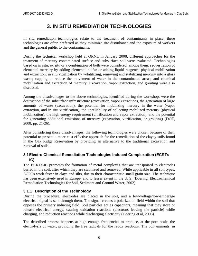
3.1.1 Description of the Technology During the procedure, electrodes are placed in the soil, and a low-voltage/low-amperage electrical signal is sent through them. The signal creates a polarization field within the soil that opposes the primary inducing field. Soil particles act as capacitors, meaning that they store or release electrical energy, causing oxidation reactions (electrons leaving the particle) while charging, and reduction reactions while discharging electricity (Doering et al, 2006).
The described process happens at high enough frequencies to produce, at the pore scale, the electrolysis of water, providing the free radicals for the redox reactions. The contaminants, in

ARC-2007-D2540-032-04 In Situ Remediation and Stabilization Technologies for Mercury in Clay Soils
10
this case metals, are desorbed from the soil in the form of ionic metal complexes, transported electro-kinetically and then deposited onto the electrodes (Burks, 2002, Doering et al., 2006).
Figure 5. ECRTs Pore Scale Redox Modela
a source: ppt Mercury cleanup through the use of electrochemical remediation technologies by Falk Doering, Ph.D, presented at the “Breaking the Mercury Cycle” Conference, in Boston, Massachusetts, 2002.
Figure 5 shows this process on the microscopic level. An electrical double layer forms around the clay particle which by its nature has a negatively charged surface. Water is held around the soil particle, forming two layers: 1) an inner layer, the hygroscopic water, where water is held by absorption to the soil, and 2) an outer layer, the hydration water or diffuse layer (Doering & Doering, 2006). Exchange of electrons and electrochemical reactions take place between the layers and between the particle and the inner layer.
Electromigration, electroosmosis and electrophoresis processes help in the desorption of the ions from the soil particle surface and its transport through the electrical field to the electrodes (Gadner, 2005).
When a direct current (DC) is applied to the electrodes in the system at high enough voltage but below the electrokinetic point (point at which resistance between electrodes >1), the dissociation energy produces the split of the molecules and as a result the following electrochemical reactions can be expected:
- metals changing oxidation states - formation of complex ions - non-polar substances converted into colloids - dissociation of water-insoluble compounds (HgS into metallic mercury)
When the DC applied is enough for the system to be above the electrokinetic point, the metals, now in the form of complex ions, are transported to the electrodes. The material of the electrodes determines the contaminant subject to treatment. For instance, for heavy metals like mercury, the cathodes are made of iron or aluminum, and the anodes are made of carbon materials, graphite, titanium or steel (Doering & Doering, 2006).
As a result of this procedure, mercury will be electrochemically plated to the electrodes, which after being removed from the soil, are subject to ex situ treatment. Stabilization of mercury at this stage can be achieved with the implementation of the sulfur polymer
Soil Particle or Colloid
Sorbed water molecule
Hydrated Anion
Outer Helmholtz Plane
Inner Helmholtz Plane
Diffuse layer
Hygroscopic Water—serves as a dielectric
A zone of redox reaction
Hydrated Cation

ARC-2007-D2540-032-04 In Situ Remediation and Stabilization Technologies for Mercury in Clay Soils
11
stabilization/solidification (SPSS) technology, described in section 3.2.2, which produces a stable mercuric sulfide residual.
During the design of a ECRTs-IC system, the electrical resistivity of the soil and the presence of other ions in the soil, like iron, must be considered in order to determine voltage and current range of power supplies. This information should be gathered during the characterization phase prior to the design of the treatment.
3.1.2 Advantages and Disadvantages to ECRTs-IC
Advantages
‐ Does not require the addition of chemicals that might harm the environment. ‐ No chemical additives are used. ‐ No excavation required. ‐ Suitable for treating contamination under buildings and natural areas with minimal
disturbance of the site. ‐ Faster results are obtained in clays and silt soils than in soils made of sand and gravel. ‐ Other heavy metals might be captured. ‐ Can be used in the remediation of all chemical forms of mercury. ‐ Estimated cost per cubic yard is $444, which is low when compare to the estimated $725
per cubic yard in the case of other technologies like low temperature thermal desorption (Burks, 2002).
Disadvantages
‐ Efficiency of the remediation is reduced by the presence of large concentrations of other ions.
‐ Promotes the separation of HgS, which is a very stable form of mercury, generating higher volumes of metallic mercury to remediate.
‐ Since the process will cause dissociation of water-insoluble compounds present in the soil, the potential for harmful reactions should be considered.
‐ Electrode arrays might damage a portion of the surrounding underground area.
3.1.3 Case Studies Using ECRTs-IC
The Union Canal in Scotland
In Scotland, at the union canal site, this technology was used to treat 220 m3 of clay/silt sediments contaminated with methyl mercury and elemental mercury, removing more than 76 kg of the pollutant. The remedial action decreased total mercury concentration from an average of 243 mg/kg to an average of 6 mg/kg in a period of 26 days (Burks, 2002).
Bench Scale with soil from Y-12 area
Sludge was prepared with the mercury contaminated soils from Y-12 (Figure 6) and then placed in a cell designed as seen in Figure 7, with capacity to hold approximately 150 L. Soil was treated for a total of 741 hours, with a recovery rate of 0.038 gm/h, removing about 55% of the mercury present: a total of 28.4 gm from the initial 52 gm. The test was not run to completion due to time and budget issues (Burks, 2002).

ARC-2007-D2540-032-04 In Situ Remediation and Stabilization Technologies for Mercury in Clay Soils
12
High iron content in the soil from Y-12 that was used in this experiment reduced the efficiency of the technology because the iron was being transported by the electrical current as well as the mercury.
Figure 6. ECRTs test cell (Burks, 2002)
Figure 7. Schematic of ECRTs-IC test cell (Burks, 2002)
3.2 In Situ Mercury Stabilization (ISMS) ISMS is a new technology that has been patented by DOE’s Brookhaven National Laboratory under U.S. patent 7,692,058. The procedure is based on promoting the formation of a stable form of mercury, mercury sulfide (HgS), which occurs when elemental mercury reacts with elemental sulfur.
3.2.1 Description of the Technology Individual extractors in the form of tubes, containing a sulfur reagent, are inserted in the soil. Mercury moves by diffusion from zones of higher concentration, in this case the soil, to lower concentration, the extractors, where a reaction between elemental sulfur and elemental mercury forms a stable and insoluble form of mercury known as cinnabar or mercury sulfide. (Fuhrmann, Heiser, & Kalb, 2010) .
Since this is a new technology, the time that the extractors must remain in the site is not yet known and may be site specific, depending on factors like soil permeability, moisture, and mercury concentration. Fuhrman et al. (2010) considered a period of days or weeks to allow the mercury‘s migration from the soil to the tubes containing the reagent. The dimensions and separation between the tubes in the contaminated soil is also yet to be determined.
Mercury extractors containing the reagent can take different forms according the needs at the site (Fuhrmann, Heiser, & Kalb, 2010), including:
‐ Long cylindrical rods inserted in the soil after drilling holes, ‐ Long spikes of solid sulfur with a sharp distal to facilitate penetration in the soil, ‐ Cylindrical plastic mesh bags filled with granular or powder sulfur polymer cement
(SPC), ‐ Hollow permeable tubes, and

ARC-2007-D2540-032-04 In Situ Remediation and Stabilization Technologies for Mercury in Clay Soils
13
‐ Electrically powered tubes for heating the soil
The reagent could vary between sulfur polymer cement (SPC), sodium sulfide, or other sulfur-like compounds and could be in the form of powder, granules or solid form, mostly depending on the extractor chosen and considerations at the site. For instance, using granules would minimize losing material, but using powder would increase the contact surface area.
Sulfur polymer cement is the recommended reagent; it was developed in 1972 for construction applications. The composition is about 95 wt% elemental sulfur and 5 wt% organic modifiers. SPC is thermoplastic and can be melted at temperatures around 120°C. In recent years, it has been used in the solidification/stabilization of contaminated hazardous wastes due to its properties of low permeability, low porosity, imperviousness to water, and high resistance to corrosive environments (Mattus, 1993).
To accelerate the kinetics of the reaction between mercury and sulfur, the inventors proposed heating the soil to 50°C, which would, of course, increase the difficulty and the cost of the remediation.
Once the mercury has been stabilized, the extractors can be removed for ex situ treatment, with the objective of reaching leachability and LDR standards established by EPA.
Since the technology is still under development, Appendix B includes a set of answers to questions about ISMS, provided by Paul Kalb, division head of Environmental Research & Technology, in the Environmental Sciences Department, at Brookhaven National Laboratory. Mr. Kalb is also one of the inventors.
3.2.2 Mercury Stabilization Using Sulfur Polymer Stabilization/Solidification Sulfur polymer stabilization/solidification (SPSS) is an ex situ treatment where the extractors are mixed with extra sulfur polymer cement. The new mix is heated at 130°C, the point at which it melts and is ready for pouring into a mold. This is followed by a period of cooling and solidifying, resulting in a “solid monolithic waste” that meets EPA’s land disposal restrictions (Kalb, Adams, & Milian, 2001, pp. 2-3). This approach requires an off-gas treatment system to be in place.
Control of the temperature is crucial during the ex situ treatment of the stabilized contaminant. Temperatures over a 150 – 160 °C range can make the material unpourable and create hydrogen sulfide (H2S) gas, which is flammable and toxic. At temperatures lower than 126°C, the sulfur mix will be only partially melted, which does not assure the proper encapsulation of the waste (Mattus, 1993).
3.2.3 Advantages and Disadvantages of ISMS
Advantages
‐ SPC is an inexpensive and commercially available material. ‐ ISMS can be used to treat mercury at various depths. ‐ The design of the individual extractors is flexible and can be used to facilitate the
extraction of the stabilized contaminant.

ARC-2007-D2540-032-04 In Situ Remediation and Stabilization Technologies for Mercury in Clay Soils
14
‐ Does not generate large amounts of waste. ‐ Does not disturb vegetation over the soil to be treated. ‐ Mercuric sulfide is very stable with Ksp = 2x10-53 (Zhong et al., 2009).
Disadvantages
‐ The tubes containing the stabilized mercury need to be subject to ex situ treatment for the waste to meet EPA’s LDR standards.
‐ This is a new technology, which implies that the efficiency and implementation cost are not known.
3.3 Nanotechnology Nanotechnology is a dynamic field that is growing rapidly and consists in the use of particles with dimensions in the range of 1 – 100 nanometers, to affect the mobility, toxicity and/or bioavailability of contaminants in their natural environment.
The nano-sized particles are characterized by enhanced reactivity and a large surface area to volume ratio, which speeds up sorption kinetics, creating applications in the remediation of groundwater, surface water, and the subsurface. The small size increases the mobility of the particles in subsurface soils and groundwater, therefore improving the ability to remediate larger areas as they disperse in the environmental media (EPA, 2008).
One of the best known technologies in this area are the nano scaled zero-valent iron (nZVI) particles, which have been successfully used in the remediation of volatile organic compounds (VOCs), trichloroethylene (TCE), polychlorinated biphenyls (PCBs), and metals such as chromium and arsenic (EPA, 2008), contaminants also present at the ORR. A recognized disadvantage of the nZVI particles is the agglomeration which decreases its mobility and reactivity.
EPA recently published data collected on 26 sites (http://clu-in.org/download/remed/nano-site-list.pdf) using nanotechnology for remediation, with several sites located in areas with clayey soils; the information collected mainly refers to remediation of TCE, VOCs and PCBs.
3.3.1 Description of the Technology Recognizing the agglomeration disadvantage of the nZVI, the present study will include as an improved alternative the use of stabilized iron phosphate nanoparticles for the in situ immobilization of metals in contaminated sites. The technology was patented by Zhao et al. 2009 (US patent 7,581,902), and involves the injection of iron sulfide (FeS) nanoparticles into the soil, using a liquid as a carrier media. It is applicable to surface or subsurface soils with variations in the method for delivering the nanoparticles to the soil, which include injection and spray of the solution.
To avoid the agglomeration of the nanoparticles, a low concentration of water soluble sodium carboxymethyl cellulose (NaCMC) is added to the mix as a stabilizer. The stabilizer’s main role is to control the growth of the nanoparticles by preventing their agglomeration, thereby preserving the small size and assuring the mobility of the particles in the soil, while also

ARC-2007-D2540-032-04 In Situ Remediation and Stabilization Technologies for Mercury in Clay Soils
15
providing a green alternative that does not harm the environment and does not affect the conductivity of the soil (Zhao et al. 2009).
Among other iron oxides, the inventors recommend using FeS for mercury remediation due to its stability, insolubility in water (solubility product constant, Ksp =8x10-19), and unavailability to biota (Zhao et al. 2009). Brown, et al., (1979) studied iron sulfide and its capacity to adsorb mercury (Hg2+ and Hg0); in their experimental work, FeS removed 95% of the mercury in solution with higher sorption rates at lower pH (~4) ranges.
Column tests conducted by Xiong et al., 2009, indicated that FeS nanoparticles are mobile in clay soil. Once the nanoparticles are injected into the soil, mercury is immobilized by ion exchange or adsorption, as follows (DOE, 2009b):
FeS(s) + Hg2+ → HgS(s) + Fe2+
FeS(s) + nHg2+ → FeS-n Hg2+
2FeS(s) + Hg0 + 4H+ → HgS(s) + 2Fe2+ + H2S + H2
3.3.2 Advantages and Disadvantages of Nanotechnology
Advantages
‐ Applicable to surface and subsurface soils. ‐ Immobilizes mercury into HgS, which is very stable in the environment. ‐ The solution for the treatment can be prepared on site. ‐ The stabilizer is a low cost, water soluble, environmentally friendly compound. ‐ Compounds used are commercially available. ‐ FeS is insoluble in water and unavailable to biota. ‐ Applicable in the remediation of groundwater and surface water as well. ‐ Iron displaced by the mercury is easily precipitated (Brown, et al.,1979). ‐ Does not generate additional waste. ‐ Low energy demand.
Disadvantages
‐ The effects of the soil pH in the kinetics of the treatment are yet to be determined. ‐ Deployment strategy needs to be designed, in terms of separation and depth of injection
points. ‐ Requires further evaluation of the geochemistry of the nanoparticle, and the effects on the
soil microorganisms.
3.4 Phytoremediation Phytoremediation is a technology based on the use of plants to remove, contain, stabilize or degrade contaminants in the environment, with applicability to organics, inorganics and heavy metals. Different approaches to the phytoremediation of metals can be considered: 1) phytoextraction, which is the removal of the contaminants by the roots and then transported to the plant tissue, 2) phytovolatilization, with which contaminants are transported from the roots to

ARC-2007-D2540-032-04 In Situ Remediation and Stabilization Technologies for Mercury in Clay Soils
16
the leaves and then volatilized, and 3) phytostabilization, with which the pollutants are immobilized in the roots of the plants.
3.4.1 Description of the Technology Due to the high level of mercury present in soils in some areas of the ORR, phytoextraction is a preferred approach that will allow the harvest of the plants for disposal or ex situ treatment as needed, without transferring high levels of elemental mercury to the atmosphere.
Phytoextraction uses plants characterized as hyper accumulators, with the capacity to concentrate high levels of the metal. The contaminant is extracted from the soil by the roots, transported by the vascular system and deposited in the shoots. Natural organic ligands speed the transport process as they contribute to the formation of “soluble non-cationic metal chelates” by sequestering metal ions that otherwise would have stayed in the roots of the plant in the form of precipitates or bound to cell of the roots (Chen et al., 2010, p.8).
Plants are harvested to remove the contaminants and treated according to CERCLA regulations (Lur et al., 2009). The process also requires continuous monitoring to evaluate the plants’ physiological status, due to phytotoxic effects of the metal in plants. This will allow the determination of the ideal harvesting time and increase efficiency.
The use of native plants is recommended since the introduction of non-native species could alter the ecosystem (Chen et al., 2010).
Another important component of the technology is the use of soil fertilizers, which requires a balance between the benefits of fertilizers that acidify the soil and therefore increase the bioavailability of metals for plant uptake and the potential for harm to the soil, in terms of changes in pH. Organic fertilizers are an alternative, with the downside of decreasing the metal bioavailability.
Since no hyperaccumulator has been found for mercury, Su et al., 2007 studied the potential for phytoremediation of three types of plants (Indian mustard, Chinese brake, and Beard grass), in different types of artificially mercury polluted soils placed in pots. One of the findings from the study was that the Chinese brake fern was suited for mercury phytoextraction as it did not present signs of stress at high concentrations of mercury, accumulating as high as 1,479 mg/kg in its shoots after 18 days.
In some applications, chelating agents are use to accelerate the plant’s rate of uptake and translocation (transport from roots to leaves) of the contaminants. This approach requires careful evaluation of side-effects, which include the formation of low biodegradable complexes, metal leaching, and toxic effects in the soil microorganisms (Lur et al., 2009).

ARC-2007-D2540-032-04 In Situ Remediation and Stabilization Technologies for Mercury in Clay Soils
17
3.4.2 Advantages and Disadvantages of Phytoremediation
Advantages
‐ Low cost, estimated $60,000 - $100,000 per acre to a depth of 50 cm (Henry, 2000). About 50-60% less expensive than excavation (Chen et al., 2009). This is equivalent to $23 – $38 per cubic yard.
‐ Permanent removal of the metal. ‐ Easy to implement. ‐ Non-intrusive. ‐ More than one contaminant can be remediated at the same time, if the plants used are
diversified accordingly (Chen et al., 2010). ‐ Reduces the amount of hazardous waste to be disposed.
Disadvantages
‐ It can only be used for surface soil contamination. ‐ Remediation takes longer than with conventional treatments, 18-60 months (Chen et al.,
2010). ‐ Uncertainty of the effect in the food chain through herbivores and omnivores (Henry,
2000). ‐ Uncertainty of the effects in the ecosystem when non-native plants are introduced. ‐ It can add pollutants to the soil from the fertilization process. ‐ Requires landfill and/or treatment of harvested plants.
ARC-2007-D2540-032-04 In Situ Remediation and Stabilization Technologies for Mercury in Clay Soils
18
4. CONCLUSIONS AND RECOMMENDATIONS
The remediation of the mercury contaminated areas like Y-12 might require a combination of technologies, according to the specific characteristics of the sub-areas, and concentrations and types of mercury present. For instance, phytoextraction can be the ideal approach for the floodplains of the EFPC and other areas where mercury is present in the surface soil as the remediation results are limited to the depth reached by the roots of the plants.
The in situ mercury stabilization (ISMS) technology and nanotechnology offer great potential for the treatment of surface and subsurface contamination and can also be adapted for removing contaminants bellow buildings, one of the challenges at Y-12. In this case, elemental mercury is stabilized as mercury sulfide, which is considered one of the principal sinks of mercury, is insoluble in water, and is highly stable in the environment, both in the presence and in the absence of oxygen.
ISMS is an environmentally friendly remediation approach, developed at the Brookhaven National Laboratory. This would therefore make it possible to pilot test and subsequently implement this technology at the ORR with an efficient use of funds, streamlining DOE’s investment in research with the actual DOE-EM mission, the cleanup of the legacy.
ECRTs-IC performance has to be evaluated in terms of the presence of other metals that will compete with mercury, reducing its efficiency. The potential for dissociating mercury sulfide (HgS), already stable, into metallic mercury needs to be further studied since breaking the bond between Hg and S will generate higher amounts of mercury that will need to be stabilized and disposed.
The four technologies are ready for bench scale and pilot tests, which will give a better perspective on the efficiency of each under the specific conditions present at ORR, and also will provide information for designing the remediation strategy.

ARC-2007-D2540-032-04 In Situ Remediation and Stabilization Technologies for Mercury in Clay Soils
19
5. REFERENCES
Andersson, A. (1979). Mercury in Soils. In J. Nriagu, The Biogeochemistry in the Environment. Ontario, Canada: Elsevier.
ATSDR. (2006). Public Health Assessment Evaluation of Potential Exposures to Contaminated Off-Site Groundwater from Oak Ridge Reservation (USDOE). Agency for Toxic Substances and Disease Registry, Federal Facilities Assessment Branch, Division of Health Assessment and Consultation , Oak Ridge, TN.
Brown, J., Bancroft, M., & Fy, W. (1979). Mercury removal from water by iron sulfide minerals. An electron spectroscopy for chemical analysis (ESCA) study. Environ. Sci. Technol. , 1142–1144.
Burks, B. L. (2002). Demostration of Electrochemical Remediation Technologies-Induced Complexation.
Chen, J., Shi, Z., Bin Hu, L., Su, Y., Han, F., & Monts, D. (2010). Site Assessment, Long-Term Monitoring and Regulatory Concerns for Application of Phytoremediation Technology for Remediation of Heavy Metal/Metalloid-Contaminated Soils. In T. Faerber, & J. Herzog, Solid Waste Management and Environmental Remediation. Nova Science Publishers Inc.
Chen, J., Yang, Z., Su, Y., Han, F., & Monts, D. (2009). Phytoremediation of Heavy Metal/Metalloid-Contaminated Soils. In R. Steinberg, Contaminated Soils: Environmental Impact, Disposal, and Treatment. Nova Science Publishers, Incor.
Devgun, J. (1993). Soil Washing as a Potentia Remediation Technology for Contaminated DOE Sites. Waste Management, (p. 20). Tucson, Arizona.
DOE. (2009b, October 23). Retrieved June 24, 2010, from DOE, Environmental Management Office: http://www.em.doe.gov/PDFs/Mercurysummit09/32Xiong-%20Nanotechnology%20for%20In%20Situ%20Mercury%20Immobilization.pdf
DOE. (2009). Characterization Plan for the 81-10 Area in the Upper East Fork Poplar Creek at the Oak Ridge Y-12 National Security Complex. Oak Ridge, TN.
DOE. (2008b). External Technical Review of the Mitigation and Remediation of Mercury Contamination at the Y-12 Plant. Office of Environmental Management, Oak Ridge, TN.
DOE. (1993). Final Report on the Background Soil Characterization Project at the Oak Ridge Reservation, Volume 3. Office of Environmental Restoration and Waste Management, Oak Ridge, TN.

ARC-2007-D2540-032-04 In Situ Remediation and Stabilization Technologies for Mercury in Clay Soils
20
DOE. (2008). Recommendations to Address Technical Uncertainties in the Mitigation and Remediation of Mercury Contamination at the Y-12 Plant. EM Center for Sustainable Groundwater and Soil Solutions, Oak Ridge, TN.
DOE. (2002). Record of Decision for Phase I Interim Source Control Actions in the Upper East Fork Poplar Creek Characterization Area. Oak Ridge, TN.
DOE. (2006). Record of Decision for Phase II Interim Remedial Actions for Contaminated Soils and Scrapyard in Upper East Fork Poplar Creek . Office of Environmental Management, Oak Ridge, Tennessee.
DOE. (1998). Report on the Remedial Investigation of the Upper East Fork Poplar Creek Characterization Area at the Oak Ridge Y-12 Plant. Volume3 Appendix D Nature and Extent of the Contamination. Office of Environmental Management, Oak Ridge, TN.
DOE. (2002(b)). Work Plan for the Building 81-10 In Situ Grouting Phase 1 Testing at the Y-12 National Security Complex. Oak Ridge, TN.
Doering, F. (2002). Electrochemical Remediation Technologies for Soil, Sediment and Ground Water. Retrieved 05 10, 2010, from http://www.containment.fsu.edu/cd/content/pdf/022.pdf
Doering, F., & Doering, N. (2006, January 10). Method for Removing Inorganic Compounds from a section of soil. US Patent 6984306. Retrieved June 08, 2010, from Patent Storm: http://www.patentstorm.us/patents/6984306/description.html
EPA. (1997). Mercury Study Report to Congress. Volume III. Fate and Transport of Mercury in the Environment.
EPA. (2008). Nanotechnology for Site Remediation Fact Sheet. Cincinnati, OH: EPA.
EPA. (2004, October). Site Superfund Innovative Technology Demonstration Bulletin, ElectroChemical Remediation Technologies (ECRTs). Retrieved May 10, 2010, from http://www.epa.gov/nrmrl/pubs/540mr04507/540mr04507.pdf
EPA. (2007). Treatment Technologies for Mercury in Soil, Waste and Water. Office of Superfund Remediation and Technology Innovation, Washington, DC .
Fuhrmann, M., Adams, J., & Kalb, P. (2004). In Situ Mercury Stabilization BNL Royalty Project Internal Status Report. Brookhaven National Laboratory, Upton, NY.
Fuhrmann, M., Heiser, J., & Kalb, P. (2010). US Patent 7,692,058 B2. Upton, NY.

ARC-2007-D2540-032-04 In Situ Remediation and Stabilization Technologies for Mercury in Clay Soils
21
Gadner, K. (2005). Electrochemical remediation and Stabilization of Contaminated Sediments. Cooperataive Institute for Coastal and Estuarine Environmental Technology (CICEET), Durham, NH.
Henry, J. (2000). An Overview of the Phytoremediation of Lead and Merury. Washcington, D.C.
Kalb, P., Adams, J., & Milian, L. (2001). Sulfur Polymer Stabilization/Solidification (SPSS) Treatment of Mixed-Waste Mercury Recovered from Environmental Restoration Activities at BNL. Brookhaven National Laboratory, Long Island, New York.
Lur, E., Becerril, J. M., Alkorta, I., & Carlos, G. (2009). Heavy Metal Phytoremediation: Microbial Indicators of Soil Health for the Assessment of Remediation Efficiency, Ch 16. In A. Singh, O. Ward, & R. Kuhad, Advances in Applied Remediation. New York: Springer-Verlag Berlin Heidelberg.
Mattus, C. (1993). Evaluation of Sulfur Polymer Cement as a Waste Form for the Immobilization of Low-Level Radioactive or Mixed Waste. ORNL.
ORNL. (1992). Status Report on the Geology of Oak Ridge Reservation. Environmental Science Division, Oak Ridge.
Rothchild, E. (1984). Investigation of Subsurface Mercury at Y-12 Plant. Oak Ridge National Lab, Environmental Science Division, Oak Ridge, TN.
Su, Y., Shiyab, S., & Monts, D. (2007). Phytoextraction and Accumulation of Mercury in Selected Plant Species Grown in Soil Contaminated with Different Mercury Compounds. WM 2007. Tucson, AZ.
Zhong, X., Feng, H., Dongye, Z., & Mark, B. (2009). Immobilization of mercury in sediment using stabilized iron sulfide nanoparticles. Water Research , 43, 5171–5179.

ARC-2007-D2540-032-04 In Situ Remediation and Stabilization Technologies for Mercury in Clay Soils
22
Appendix A
Formations Underlying the Oak Ridge Reservation (ATSDR, 2006, p. B3)
Geologic Feature Geology Description Fort Payne Chert Bluish-gray
Limestone Average thickness 100-250 ft. Contains water in secondary openings.
Chattanooga Shale Black fissle shale About 25 ft thick. Very dark to black carbonaceous shale. Low porosity. Low permeability.
Rockwood Formation
Greenish to Brownish Shale, Limestone
Thickness ranges from 150-1000 ft. Limited outcrop results in limited recharge. Groundwater occurs in fractures
Sequatchie Formation
Shale, Limestone Near ORR thickness of about 100 ft. Poor aquifer. Groundwater occurs in fractures
Reedsville Shale Shale Near ORR thickness ranges from 250-400 ft. Poor aquifer. Groundwater occurs in fractures.
Chickamauga Group
Limestone Approximately 2000 ft thick. Aquitard. Groundwater occurs in fractures. ORNL and ETTP are built on this group.
Knox Group Dolomite, Limestone
Thickness ranges from 2000-4000 ft. Most important aquifer in the ORR area. Large springs are common. Variable flow rates from several gpm to several thousand gpm. Massive calcareous unit.
Maynardville Formation
Limestone, Dolomite
Relatively thin (thickness 60-250 ft). Aquifers. Generally yields up to 200 gpm. Off site contamination of Y-12 occurs in this formation.
Conasauga Group Shale, Limestone, Dolomite
Thickness can be up to 2000 ft. Aquitard. Contains the largest waste management areas at ORR. Very limited migration of contaminant plumes. Most groundwater resurfaces to surface water. Limestone layers retard downward migration of groundwater.
Rome Formation Shale, Siltstone Approximately 1500 ft thick. Groundwater occurs in factures. Upper zone is more permeable than lower zone. Springs are common.

ARC-2007-D2540-032-04 In Situ Remediation and Stabilization Technologies for Mercury in Clay Soils
23
Appendix B
Answers from Paul Kalb (pdk), Division Head Environmental Research & Technology, Environmental Sciences Department, Brookhaven National Laboratory ([email protected])
How to determine dimensions and the distance between the individual mercury extractors?
[pdk:] “It is not possible to make those determinations from the laboratory scale data we have available at this time. It may be possible to eventually model this based on vapor pressure and diffusion processes but we first need a lot more empirical data to define the system and its capabilities and specifically determine spacing and sizing issues. This can only be derived through extensive scale-up testing using actual soil under controlled conditions”
What kind of soil characteristics would you need to determine that? Since Elizabeth is working on a site characterization for a small area at Y-12, I might be able to suggest getting the needed data.
[pdk:] “We would want to know basic soil types, composition, soil grain size and distribution, permeability, average moisture content and seasonal variability, and possibly presence of other metals. We would also eventually need accurate characterization of the Hg content in the soil, variability, distribution, and speciation”
For how long should the treatment rods be kept in the soil, is there a saturation point?
[pdk:] “This is also information that will be determined through scale-up testing and will depend on the in situ kinetics which in turn are a function of temperature, moisture conditions and other parameters. The rods will have a finite saturation point but under most Hg concentration conditions should be able to continue to be effective without having to be replaced”
How about the depth? To which depth do you think the technology can be applied?
[pdk:] “We do not have data on effective penetration depth for the rods and clearly this is a parameter that must be defined. However, from a practical perspective we should be able to install treatment rods to any depth above the water table where Hg contamination is present”

ARC-2007-D2540-032-04 In Situ Remediation and Stabilization Technologies for Mercury in Clay Soils
24
Appendix C
In Situ Remediation Technologies for Mercury Contaminated Clay Soils.
Technology Description Advantages Disadvantages ECRTs-IC Promotes the
formation of metal complexes that are transported to electrodes buried in the soil, after which they are stabilized and removed.
No chemical additives are used. No excavation required. Suitable for treating contamination under buildings. Minimal disturbance of natural areas. Other heavy metals might be captured. Effective for remediation of all chemical forms of mercury. Estimated cost per cubic yard is $444 (Burks, 2002).
Promotes the separation of HgS, which is already very stable in the environment. Large concentration of other ions reduces the efficiency. Damage of the surrounding underground by the electrode arrays
ISMS Individual extractors containing sulfur reagent, are placed in the soil. Elemental mercury is stabilized by forming mercury sulfide.
It can be used to treat mercury contamination at various depths. No excavation required. Required sulfur reagent is commercially available. Low energy demand. Does not generate large amounts of waste.
Individual extractors need to be treated ex situ before disposal.
Nanotechnology Iron sulfide nanoparticles mixed with a stabilizer in a liquid carrier, are injected in the soil, immobilizing mercury by adsorption.
Applicable to surface and subsurface soils. Immobilizes mercury into HgS, which is very stable in the environment. The solution for the treatment can be prepared on site. Compounds used are environmentally friendly and commercially available. Applicable in the remediation of soil, ground and surface water. Low energy demand. Does not generate additional waste.
The effects of the soil’s pH in the kinetics of the treatment are yet to be determined. Requires further evaluation of the geochemistry of the nanoparticles Effects on the soil microorganisms need to be further study.
Phytoremediation Plants are used to extract mercury from the soil, and translocated to the shoots. Plants are harvested and treated ex-situ.
Permanent removal of the metal. Easy to implement. Low cost. No energy demand. Non-intrusive. More than one contaminant can be remediated at the same time, if the plants are diversified. Reduces the amount of hazardous waste to be disposed.
Only suitable for surface soil contamination. Remediation takes longer than with conventional treatments. Uncertainty of the effect in the food chain through herbivores. Uncertainty of the effects in the ecosystem when non-native plants are introduced. It can add pollutants to the soil from the fertilization process. Requires landfill and/or treatment of harvested plants.

ARC-2007-D2540-032-04 In Situ Remediation and Stabilization Technologies for Mercury in Clay Soils
25
Appendix D
Important Contacts
In Situ Stabilization Technology
Paul Kalb Division Head Environmental Research & Technology Environmental Sciences Dept. Brookhaven National Laboratory
Phone: 631-344-7644 Fax: 631-344-4486 Email: [email protected] Web: http://www.bnl.gov/des/ERTD
Nanotechnology
Zhong (John) Xiong, Ph.D., P.E. Project Engineer AMEC Geomatrix, Inc. 510 Superior Avenue, Suite 200 Newport Beach, CA 92663 Phone: 949 642 0245 Email: [email protected]
Phytoremediation
F. X. Han, Ph.D. Associate Research Professor Institute for Clean Energy Technology Mississippi State University 205 Research Blvd, Starkville, MS 39759 Phone:662-325-7380, Fax: 662-325-8465 Email: [email protected] Web: http://www2.msstate.edu/~hxiang/