Embed Size (px)
Citation preview
simatic pcs 7
A5E00295894D-01 GN: 30340_LDS 6
Operating Instructions Edition 10/2004
Siemens Aktiengesellschaft
Automation and DrivesProcess Instrumentation and Analytics 76181 KARLSRUHEGERMANY
LDS 6In-situ Laser Gas Analyzer
A5E00295894-01 www.siemens.com/processinstrumentation
@1PA5E00295894@
g yA5E00295894
gas analysis

1

s
LDS 6 In-situ Laser Gas Analyzer
Operating Instructions A5E00295894-01 Release 10/2004

The reproduction, transmission or use of this document or its contents is not permitted without express written authority. Offenders will be liable for damages. All rights created by the granting of patents or registration of a design are reserved. Technical data subject to change without notice.
Weitergabe sowie Vervielfältigung dieser Unterlage, Verwertung und Mitteilung ihres Inhaltes nicht gestattet, soweit nicht ausdrücklich zugestanden. Zuwiderhandlungen verpflichten zu Schadenersatz. Alle Rechte vorbehalten, insbesondere für den Fall der Patenterteilung oder GM-Eintragung. Technische Änderungen vorbehalten.
Toute communication ou reproduction de ce document, toute exploitation ou communication de son contenu sont interdites, sauf autorisation expresse. Tout manquement à cette règle est illicite et expose son auteur au versement de dommages et intérêts. Tours nos droits sont réservés pour le cas de la délivrance d'un brevet ou celui de l'enregistrement d'un modèle d'utilité. Modifications techniques sont réservées.
La divulgación y reproducción de este documento asi como el aprovechamiento de su contenido, no están autorizados, a no ser que se obtenga el consentimiento expreso, para ello. Los infractores quedan obligados a la indemnización por daños y perjucios. Se reservan todos los derechos, en particular para el caso de concesion de Patente o de Modelo de Utilidad. Salvo modificaciones ténicas.
La trasmissione a terzi e la riproduzione di questa documentazione, cosiccome lo sfruttamento del suo contenuto non è permesso, se non autorizzato per iscritto. Le infrazioni comporteranno una richiesta di danni. Tutti i diritti sono riservati, in particolare nel caso di brevetti. Modifiche tecniche possibili.
ULTRAMAT, OXYMAT, CALOMAT, SIPAN are SIEMENS registered trademarks. All other product or system names are (registered) trademarks of their respective owners and must be treated accordingly. According to the German law on units in measuring technology, data in inches only apply to devices for export.
ULTRAMAT, OXYMAT, CALOMAT, SIPAN sind Marken der SIEMENS AG. Die übrigen Bezeichnungen in diesem Handbuch können Marken sein, deren Benutzung durch Dritte für deren Zwecke die Rechte der Inhaber verletzen können. Die Angaben in Zoll (inch) gelten gemäß dem Gesetz über Einheiten im Meßwesen" nur für den Export.
ULTRAMAT, OXYMAT, CALOMAT, SIPAN sont des marques déposées de SIEMENS AG. D'autres dénominations utilisées dans ce document peuvent également être des marques déposées dont l'utilisation par des tiers à leurs propres fins peut enfreindre les droits des propriétaires desdites marques.
ULTRAMAT, OXYMAT, CALOMAT, SIPAN son marcas registradas de SIEMENS AG. Las otras designaciones que figuran en este documento puenden ser marcas cuya utilización por terceros para sus propios fines puede violar los derechos de los proprietarios de dichas marcas. Conforma a la "Ley sobre las unidades de medida", las dimensiones en pulgadas sólo son válidas para la exportación.
ULTRAMAT, OXYMAT, CALOMAT, SIPAN sono marchi registrati di SIEMENS AG. Le denominazioni di altri prodotti menzionati in questa documentazione possono essere marchi il cui uso da parte di terzi può violare i diritti di proprietà. Conformemente alla "Legge sulle unità di misura" i dati in pollici valgono soltanto per l'esportazione.
SIEMENS AG Automation and Drives Process Instrumentation D-76181 Karlsruhe Siemens Aktiengesellschaft
© Siemens AG 2004 Subject to changes without prior notice
Order no. A5E00295894 Printed in Germany AG 1004 De 0,1 84 PU
CONTENT
User Information. . . . . . . . . . . . . . . . . . . . . . . . . . . . . . . . . . . . . . . . . . . . . . . . . . 11.1 Customer Information . . . . . . . . . . . . . . . . . . . . . . . . . . . . . . . . . . . . . . . . . . . . . . 11.2 General Information . . . . . . . . . . . . . . . . . . . . . . . . . . . . . . . . . . . . . . . . . . . . . . . . 11.3 Notes in Using this Manual . . . . . . . . . . . . . . . . . . . . . . . . . . . . . . . . . . . . . . . . . . . 21.4 Danger Information . . . . . . . . . . . . . . . . . . . . . . . . . . . . . . . . . . . . . . . . . . . . . . . . 21.5 Approved Use . . . . . . . . . . . . . . . . . . . . . . . . . . . . . . . . . . . . . . . . . . . . . . . . . . . . . 31.6 Qualified Personnel. . . . . . . . . . . . . . . . . . . . . . . . . . . . . . . . . . . . . . . . . . . . . . . . . 31.7 Warranty Information . . . . . . . . . . . . . . . . . . . . . . . . . . . . . . . . . . . . . . . . . . . . . . . 41.8 Supply and Delivery . . . . . . . . . . . . . . . . . . . . . . . . . . . . . . . . . . . . . . . . . . . . . . . . 41.9 Standards and Regulations . . . . . . . . . . . . . . . . . . . . . . . . . . . . . . . . . . . . . . . . . . . 4
Installation Guidelines . . . . . . . . . . . . . . . . . . . . . . . . . . . . . . . . . . . . . . . . . . . . . 52.1 Safety Information . . . . . . . . . . . . . . . . . . . . . . . . . . . . . . . . . . . . . . . . . . . . . . . . . 52.2 Installation Requirements . . . . . . . . . . . . . . . . . . . . . . . . . . . . . . . . . . . . . . . . . . . . 62.2.1 General Information . . . . . . . . . . . . . . . . . . . . . . . . . . . . . . . . . . . . . . . . . . . . . . . . 62.3 Electric Connections . . . . . . . . . . . . . . . . . . . . . . . . . . . . . . . . . . . . . . . . . . . . . . . . 82.3.1 Power Supply Connection. . . . . . . . . . . . . . . . . . . . . . . . . . . . . . . . . . . . . . . . . . . . 82.3.2 Connection of the Hybrid Cable . . . . . . . . . . . . . . . . . . . . . . . . . . . . . . . . . . . . . . . 92.3.3 Connection of Signal Cables . . . . . . . . . . . . . . . . . . . . . . . . . . . . . . . . . . . . . . . . .102.3.4 Pin Assignment of LDS 6 . . . . . . . . . . . . . . . . . . . . . . . . . . . . . . . . . . . . . . . . . . . .122.4 The Sensor CD 6 . . . . . . . . . . . . . . . . . . . . . . . . . . . . . . . . . . . . . . . . . . . . . . . . . .132.4.1 General . . . . . . . . . . . . . . . . . . . . . . . . . . . . . . . . . . . . . . . . . . . . . . . . . . . . . . . . .132.4.2 Mounting of Specific Flanges . . . . . . . . . . . . . . . . . . . . . . . . . . . . . . . . . . . . . . . .142.4.3 Installing and Aligning CD 6 . . . . . . . . . . . . . . . . . . . . . . . . . . . . . . . . . . . . . . . . .142.4.3 Mechanical Installation. . . . . . . . . . . . . . . . . . . . . . . . . . . . . . . . . . . . . . . . . . . . .142.5 Dimensional Drawings . . . . . . . . . . . . . . . . . . . . . . . . . . . . . . . . . . . . . . . . . . . . .16
Operation. . . . . . . . . . . . . . . . . . . . . . . . . . . . . . . . . . . . . . . . . . . . . . . . . . . . . . . 193.1 General . . . . . . . . . . . . . . . . . . . . . . . . . . . . . . . . . . . . . . . . . . . . . . . . . . . . . . . . .193.2 Input sequence . . . . . . . . . . . . . . . . . . . . . . . . . . . . . . . . . . . . . . . . . . . . . . . . . . .213.3 Summary of Input Functions . . . . . . . . . . . . . . . . . . . . . . . . . . . . . . . . . . . . . . . .243.3.1 Analyzer Status . . . . . . . . . . . . . . . . . . . . . . . . . . . . . . . . . . . . . . . . . . . . . . . . . . .263.3.2 Calibration. . . . . . . . . . . . . . . . . . . . . . . . . . . . . . . . . . . . . . . . . . . . . . . . . . . . . . .283.3.3 Measuring Range . . . . . . . . . . . . . . . . . . . . . . . . . . . . . . . . . . . . . . . . . . . . . . . . .293.3.4 Parameters . . . . . . . . . . . . . . . . . . . . . . . . . . . . . . . . . . . . . . . . . . . . . . . . . . . . . .293.3.5 Configuration . . . . . . . . . . . . . . . . . . . . . . . . . . . . . . . . . . . . . . . . . . . . . . . . . . . .32
Alarms . . . . . . . . . . . . . . . . . . . . . . . . . . . . . . . . . . . . . . . . . . . . . . . . . . . . . . . . . 414.1 Alarm Response. . . . . . . . . . . . . . . . . . . . . . . . . . . . . . . . . . . . . . . . . . . . . . . . . . .414.2 Maintenance Request Alarm. . . . . . . . . . . . . . . . . . . . . . . . . . . . . . . . . . . . . . . . .424.3 Faults Alarm . . . . . . . . . . . . . . . . . . . . . . . . . . . . . . . . . . . . . . . . . . . . . . . . . . . . .434.4 Transmission Alarm. . . . . . . . . . . . . . . . . . . . . . . . . . . . . . . . . . . . . . . . . . . . . . . .444.5 Limit Alarm . . . . . . . . . . . . . . . . . . . . . . . . . . . . . . . . . . . . . . . . . . . . . . . . . . . . . .454.6 Function Control Alarm. . . . . . . . . . . . . . . . . . . . . . . . . . . . . . . . . . . . . . . . . . . . .45
Maintenance and Service . . . . . . . . . . . . . . . . . . . . . . . . . . . . . . . . . . . . . . . . . 475.1 The Central Unit . . . . . . . . . . . . . . . . . . . . . . . . . . . . . . . . . . . . . . . . . . . . . . . . . .47
iLDS 6 – In-situ laser gas analyzerOperating instructions A5E00295894-01
5.1.1 Cleaning Instructions . . . . . . . . . . . . . . . . . . . . . . . . . . . . . . . . . . . . . . . . . . . . . .475.2 Cross Duct Sensor . . . . . . . . . . . . . . . . . . . . . . . . . . . . . . . . . . . . . . . . . . . . . . . . .475.2.1 Cleaning the Wedge Windows . . . . . . . . . . . . . . . . . . . . . . . . . . . . . . . . . . . . . . .475.2.2 Alignment of the Sensors . . . . . . . . . . . . . . . . . . . . . . . . . . . . . . . . . . . . . . . . . . .485.3 Calibration Check . . . . . . . . . . . . . . . . . . . . . . . . . . . . . . . . . . . . . . . . . . . . . . . . .535.4 Reconfiguration of Temperature Compensation . . . . . . . . . . . . . . . . . . . . . . . . .535.4.1 Manual to external . . . . . . . . . . . . . . . . . . . . . . . . . . . . . . . . . . . . . . . . . . . . . . . .535.4.2 External to manual . . . . . . . . . . . . . . . . . . . . . . . . . . . . . . . . . . . . . . . . . . . . . . . .545.5 Reconfiguration of Pressure Compensation . . . . . . . . . . . . . . . . . . . . . . . . . . . . .545.5.1 Manual to external . . . . . . . . . . . . . . . . . . . . . . . . . . . . . . . . . . . . . . . . . . . . . . . .545.5.2 External to manual . . . . . . . . . . . . . . . . . . . . . . . . . . . . . . . . . . . . . . . . . . . . . . . .555.6 Reconfiguration of the Path Length . . . . . . . . . . . . . . . . . . . . . . . . . . . . . . . . . . .55
Technical Description . . . . . . . . . . . . . . . . . . . . . . . . . . . . . . . . . . . . . . . . . . . . . 576.1 Introduction . . . . . . . . . . . . . . . . . . . . . . . . . . . . . . . . . . . . . . . . . . . . . . . . . . . . .576.2 Overview . . . . . . . . . . . . . . . . . . . . . . . . . . . . . . . . . . . . . . . . . . . . . . . . . . . . . . . .586.2.1 The Central Unit . . . . . . . . . . . . . . . . . . . . . . . . . . . . . . . . . . . . . . . . . . . . . . . . . .586.2.2 The Hybrid Cable. . . . . . . . . . . . . . . . . . . . . . . . . . . . . . . . . . . . . . . . . . . . . . . . . .586.2.3 The Sensor CD 6 . . . . . . . . . . . . . . . . . . . . . . . . . . . . . . . . . . . . . . . . . . . . . . . . . .596.2.4 The Ex Sensor CD 3002Ex . . . . . . . . . . . . . . . . . . . . . . . . . . . . . . . . . . . . . . . . . . .606.2.5 Protecting the Optical Surface . . . . . . . . . . . . . . . . . . . . . . . . . . . . . . . . . . . . . . .606.3 Measurement Principle . . . . . . . . . . . . . . . . . . . . . . . . . . . . . . . . . . . . . . . . . . . . .626.4 Mode of Operation . . . . . . . . . . . . . . . . . . . . . . . . . . . . . . . . . . . . . . . . . . . . . . . .646.4.1 Single Line Spectroscopy . . . . . . . . . . . . . . . . . . . . . . . . . . . . . . . . . . . . . . . . . . .656.4.2 The Second Harmonic. . . . . . . . . . . . . . . . . . . . . . . . . . . . . . . . . . . . . . . . . . . . . .666.5 Spans. . . . . . . . . . . . . . . . . . . . . . . . . . . . . . . . . . . . . . . . . . . . . . . . . . . . . . . . . . .676.6 Technical Specification . . . . . . . . . . . . . . . . . . . . . . . . . . . . . . . . . . . . . . . . . . . . .68
Spare Parts List . . . . . . . . . . . . . . . . . . . . . . . . . . . . . . . . . . . . . . . . . . . . . . . . . . 737.1 Spare Parts . . . . . . . . . . . . . . . . . . . . . . . . . . . . . . . . . . . . . . . . . . . . . . . . . . . . . .737.1.1 Ordering Instructions . . . . . . . . . . . . . . . . . . . . . . . . . . . . . . . . . . . . . . . . . . . . . .737.1.2 Spare Parts List . . . . . . . . . . . . . . . . . . . . . . . . . . . . . . . . . . . . . . . . . . . . . . . . . . .737.2 Return Deliveries . . . . . . . . . . . . . . . . . . . . . . . . . . . . . . . . . . . . . . . . . . . . . . . . . .767.2.1 Addresses for Spare Parts and Returned Deliveries . . . . . . . . . . . . . . . . . . . . . . .767.2.2 Returned Deliveries Form . . . . . . . . . . . . . . . . . . . . . . . . . . . . . . . . . . . . . . . . . . .77
ii LDS 6 – In-situ laser gas analyzerOperating instructions A5E00295894-01

User Information
User Information 11.1 Customer Information
Please read this Instruction Manual before you start to work with the Siemens LDS 6 and its cross duct sensor CD 6. The manual contains important information and data. Its observance will guarantee the correct functioning of the analyzer system;alarm significantly help you to use the equipment leading to reliable results as well as save you from servicing costs.
1.2 General Information
The product described in this manual has left the factory in per-fect and tested conditions. In order to retain this state and to achieve correct and safe operation of the product, it must only be used as described by the manufacturer. In addition, the correct and safe operation of this product depends on its proper trans-port, storage and installation as well as careful operation and maintenance.
This manual contains the information required for the approved use of LDS 6. It has been prepared for technically qualified per-sonnel who have been specially trained or who possess appropri-ate knowledge in the field of instrumentation and control, referred to further as automation technology.
Knowledge of the safety information and warnings given in this manual and their technically correct implementation are prereq-uisites for danger-free installation and commissioning and for safety during operation and maintenance of the described prod-uct. Only qualified persons have the required specific knowledge to correctly interpret the general safety information and warn-ings given in this manual and thus apply them to the particular application.
This manual is delivered together with the analyzer, even if due to logistic reasons a separate ordering is also possible. For obvi-ous reasons this manual cannot cover all possible details or appli-cations related to the different versions of the product. Should you require further information, or should particular problems which are not deeply handled within this manual arise, help can be requested through your local Siemens office or representa-tive.
LDS 6 – In-situ laser gas analyzerOperating instructions A5E00295894-01
1

User Information
NOTEWhen considering use of the analyzer for new research and devel-opment applications, we recommend that you discuss your applica-tion with our specialist department.
1.3 Notes in Using this Manual
This manual describes the applications of the equipment and how you can start it up, operate it and service it.
Warning and information texts are of particular importance. These are highlighted from the rest of the text and specially iden-tified by appropriate icons providing valuable tips on how to avoid improper handling.
1.4 Danger Information
Enclosed you will find all the necessary information regarding safety and warnings to prevent danger to the life and health of users and/or maintenance personnel as well as to avoid damage to property. This information is specially identified by icons accompanying the explanation text. The terms used in this man-ual and the information on the product itself, have the following meaning:
WARNING
Warning means that death or severe personal injury and/or substan-tial damage to property may occur if the appropriate safety precau-tions are not observed.
CAUTION
Caution means that slight personal injury or damage to property can occur if the appropriate safety precautions are not observed.
NOTENote relates to important information on the handling of the prod-uct or the respective part of the manual to which particular atten-tion should be paid.
LDS 6 – In-situ laser gas analyzerOperating instructions A5E00295894-01
2
User Information
1.5 Approved Use
Approved use in the terminology of this manual means that this product may only be used for the applications described in the Catalogue and in the Technical Description and only in conjunc-tion with other devices and components which have been rec-ommended or approved of by Siemens.
The product described in this manual has been developed, manu-factured, tested and documented taking into account the appro-priate safety standards. No risk therefore exists in the normal case with respect to damage to property or health of persons if the handling guidelines and safety information described for configuring, assembly, approved use and maintenance are observed. This device has been designed in such a way that safe isolation is guaranteed between the primary and secondary cir-cuits. Connected low voltages must also be generated using safe isolation.
WARNING
After removing the product housing or guard, or after opening the system cabinet, certain parts incorporated in the device/systems may carry dangerous voltages. Therefore it is important that only suitable qualified personnel work on it. These persons must be entirely acquainted with all the sources of danger as well as all the maintenance measures described within this Manual.
1.6 Qualified Personnel
Severe personal injury and/or extensive damage to property may occur following unqualified work on the device/system or the failure to observe the warnings described in the manual or on the device/system cabinet. Therefore only suitably qualified per-sonnel may work on it.
Persons considered as qualified in regards to the safety informa-tion given in this manual and/or on the product itself are those that:
• are either configuring engineers familiar with the safety con-cepts of automation technology; or
• have been trained as operators in the use of automation tech-nology equipment and are acquainted with the contents of this manual which refer to operation; or
• have been appropriately trained as commissioning and/or maintenance personnel for such automation technology equipment or are authorized to energize, ground and tag cir-cuits and devices/systems in accordance to established safety practices.
LDS 6 – In-situ laser gas analyzerOperating instructions A5E00295894-01
3

User Information
1.7 Warranty Information
We wish to specifically draw your attention to the fact that the design of the product is exclusively and completely described in the sales contract. The contents of this product documentation are not part of a previous or existing agreement, commitment or statutory right and do not change these. All commitments on behalf of Siemens are given in the respective sales contract that also contains the complete and solely applicable warranty condi-tions. These conditions are neither extended nor limited by the contents of this Instruction Manual.
1.8 Supply and Delivery
The respective scope for delivery according to the valid contract is listed on the shipping documents.
Upon opening, please observe the corresponding information on the packaging material. Check that the delivery is complete and undamaged. In particular, compare the order numbers on the labels (if present) with the ordering data.
Please retain the packaging material if possible so that you can reuse it if it is necessary to return the device.
1.9 Standards and Regulations
The harmonized European standards have been applied as far as possible to the specification and production of this device. If no harmonized European standards have been applied, the stan-dards and regulations for the Federal Republic of Germany apply (see also “Technical Description” on page 57).
The standards and regulations for each country must be observed when using the product outside its range of applica-tion.
LDS 6 – In-situ laser gas analyzerOperating instructions A5E00295894-01
4

Installation Guidelines
Installation Guidelines 22.1 Safety Information
Electrical Safety
WARNING
It is essential that you observe the given information and warnings!
Certain parts in the gas analyzer LDS 6 carry dangerous voltages. The housing must be closed and grounded before switching on the analyzer. Death, personal injury and/or damage to persons and/or property may result if this is not observed.
The cross duct sensor CD 6 meets all regulations specified in the present EU regulations (LVD regulation 73/23/EEC and EMC regu-lation 89/366/EEC) as well as those of the American and Cana-dian markets (UL- and CSA regulations).
The device has to be used in an industrial environment.
Laser SafetyAll lasers used by LDS 6 are of class 1. The emitted laser light is in most cases invisible (near infrared) and the intensity is low enough so that the unprotected eye is not damaged. However, if you look directly into the beam with focusing optics (like binocu-lars) there is a risk of eye damage. LDS 6 has warning labels at appropriate positions according to SSI FS 1980:2 chapter 5.
Heat SafetySome metal parts and piping placed near the sensors are at ele-vated temperatures. The reason is high temperature purging - either from steam or from air. These parts are either isolated or equipped with protective metal sheets.
Pressure SafetyIn some applications the process can be over pressurized. Nor-mally this is not a situation where the measurements will be ade-quate. Still, from a security aspect, the sensor is tested at 6000 hPa. This pressure value should not be exceeded in operational conditions.
Explosion Protection - Ex II 1G D T135°C EEx ia IIC T4The LDS 6, with a central unit and sensor interconnected with optical fibers, is in its nature very explosion safe. Only a limited, low energy part of the electronics is located at the measurement site. The distance between the central unit and the sensors can be several hundred meters. The LDS 6 system is available in an Ex version and is then delivered with an approval for use in hazard-ous environments in which explosive gases are in use. The ATEX
LDS 6 – In-situ laser gas analyzerOperating instructions A5E00295894-01
5

Installation Guidelines
certificate is a system certificate and is only valid if LDS 6 is installed according to the instructions given in the certificate.
ApprovalThe concept of the Ex approval is that the central unit is unchanged from a standard unit and that a special Ex sensor pair (CD 3002Ex) is used in the hazardous zone. In addition to this an explosion protection barrier is added before entry into the haz-ardous zone. An absolute condition for the approval is that the equipment is set up according to the Siemens Laser Analytics drawing, ADM 3040 3050.
The protection is as follows:
Cross Duct Sensor - Ex II 1G D T135° EEx ia IIC T4.
Central (Barrier) Unit - Ex II (1)G D T135° [EEx ia] IIC T4.
• Equipment Group: Group II - Surface.
• Equipment Category: Category 1G D - Zone 0. Flammable material can be present continuously, frequently or for long periods, in gas and dust.
• Type of protection: EEx ia. The equipment present in the haz-ardous area is intrinsically safe.
• Explosion group: IIC. This corresponds to a gas group contain-ing Acetylene and Hydrogen.
• Temperature class: T4. The maximum surface temperature on the equipment is 135°C and the ignition temperature of the gas or vapor is between 135°C and 200°C.
• The sensor housing protection is IP 65 and the ambient tem-perature must be between -30°C and +60°C.
LiabilityFollowing commissioning, the total responsibility is with the owner.
2.2 Installation Requirements
2.2.1 General Information
Mounting ConditionsThe central unit LDS 6, should be placed on a location which is dust-free and as free as possible from vibrations. The distance between the central unit and the measurement point, i.e. the sensor, may not exceed 1.000 meters.
During operation the permissible surrounding air temperature is 5°C to 45°C, with a relative humidity of maximum 85% non-con-
LDS 6 – In-situ laser gas analyzerOperating instructions A5E00295894-01
6

Installation Guidelines
densing, around the central unit. Also ensure that the unit is not exposed to direct solar radiation. If these conditions can’t be ful-filled the LDS 6 must be installed in a cabinet with controlled environment.
NOTEAs condensing is normally a problem when moving the device from outside to inside a building it is recommended that the device should be adapted to room climate for a couple of hours before starting it.
The back of the unit must be accessible. There should be at least 10 cm of free space behind the LDS 6 to accommodate the signal and hybrid cables. To meet the safety requirements for air con-vection and cooling there must be a free space of at least 5 cm above and at least 3 cm below LDS 6.
PreparationsBefore the sensor can be installed at the measurement point, flanges have to be welded into the measuring site. The flanges must be DN65/PN6 or ANSI 4”/150 lbf with an inner diameter of minimum 55 mm and maximum 70 mm. The flanges must pro-trude at least 150 mm from the wall and 0-30 mm into the fur-nace or funnel. Flange tubes should never be longer than the purge tube (which has a standard length of 360 mm). If longer flange tubes are needed for any reason special purge tubes (longer) have to be used.
The flanges should be aligned before mounting the sensors. (See “Alignment of the Sensors” on page 48, for closer instructions on this process).
SensorsDo not install the sensors without access to purging air or steam (see “Protecting the Optical Surface” on page 60). Mount and align the two sensor units, transmitter and receiver, using some kind of alignment tool. (The supplied alignment kit is recom-mended). Make sure to have sufficient space around the sensors, to ensure easy service.
Hybrid CablesThe hybrid cables should be installed so that they are protected from mechanical wear such as sharp edges or moving parts. Always keep the protective tube and the inside protective cap covering the single mode fiber (E2000 connector) so it is pro-tected from dust. The operating temperature for the cables is -40 to +80°C and the installation temperature is -20 to +80°C. The bending radius of the cables may never be smaller than 100 mm.
LDS 6 – In-situ laser gas analyzerOperating instructions A5E00295894-01
7
Installation Guidelines
NOTEThroughout the entire installation, keep the fiber ends protected by the protective tubes; observe that these should only be removed by authorized personnel.
There are three kinds of cables used for the LDS 6 depending on the application:
• Hybrid cables for all types of systems except oxygen. These are installed between the LDS 6 and the transmitter sensor.
• Hybrid cables for oxygen systems only, also installed between the LDS 6 and the transmitter sensor.
• Loop cables, same for all systems, are installed between the transmitter sensor and the receiver sensor.
2.3 Electric Connections
WARNING
The respective country-specific standards for the installation of power systems with rated voltages below 1000 V must be followed. Failure to observe these regulations may result in death, personal injury and/or damage to property.
2.3.1 Power Supply Connection
General• Check that the local voltage agrees with that specified on the
label on the analyzer.
• The cable must be tested according to IEC 60227 or IEC 60245 and must be suitable for 70 °C.
• The power cable must be routed separately from the hybrid cables.
Detachable Cord• The analyzer is supplied with an appliance plug which may
only be connected to the power supply by qualified personnel (see “Qualified Personnel” on page 3). The cross-section of the conductors must be at least 1 mm2. The phase conductor must be connected to the identified position (L).
• Only detachable power supply cords tested by an accepted third party Lab accredited for the region where the unit is to be used is allowed. This cord must be suitable for the rated current and limited in length. This flexible cord must also be
LDS 6 – In-situ laser gas analyzerOperating instructions A5E00295894-01
8

Installation Guidelines
suitable for an ambient temperature of 70 °C and is not allowed to be mounted in building installations.
• As the kind of appliance inlet is only suitable for 70 °C ambi-ent temperature the power cord must be kept away with suit-able means from surfaces of more than 70 °C at max. rated operation conditions.
• It is not allowed to install a switch within the power supply cord.
Building Installation• A circuit-breaker shall be part of the building installation. It
must be provided in the immediate vicinity of the analyzer (see rating plate for loading capacity). It must also be labeled to correlate with the instrument.
2.3.2 Connection of the Hybrid CableThe hybrid cable is connected at the back of the central unit, where its two optical cables and one power wire are attached, as shown in the picture “LDS 6 cable connections” on page 9.
WARNING
Keep the fiber end protected, by the protective tube, until it is time for connection. Only authorized personnel are entitled to remove the protective tube and proceed with the connecting operation.
Figure 2.1 LDS 6 cable connections
21 3 4 5 6
LDS 6 – In-situ laser gas analyzerOperating instructions A5E00295894-01
9

Installation Guidelines
2.3.3 Connection of Signal Cables
CAUTION
The signal voltages must be electrically isolated extra-low voltages (SELV). The max. voltage potential accessible to persons is 33 Veff or 46,7 V peak or 70 V dc. If several SELV voltages are available, then it is possible that the sum of these potentials is higher than that allowed to get in contact with the human body.
WARNING
The signal cables must only be connected to devices which guaran-tee safe isolation from their power supply.
If signals (i.e. analog output 4-20 mA) are to be routed into a potentially explosive atmosphere of zone 1, they must be intrin-sically safe. Supplementary retrofitting of the analyzer with energy-limiting modules is necessary.
The Ex identification of these modules must be clearly visible on the housing:
• The signal cables in the rack mount analyzer are connected to the DSUB plugs at the rear.
• RC elements must be connected according to the figure “Spark suppression” on page 11 as a measure to suppress the generation of sparks across the relay contacts (i.e. limit relays). Note that the RC element results in a drop-out delay for an inductive component (i.e. solenoid valve). The RC ele-ment should therefore be dimensioned according to the fol-lowing rule-of-thumb:
R [Ω] ≅ 0.2 x RL [Ω] C [µF] ≅ IL [A]
Additionally, make sure that you only use a non-polarized capacitor C.
1. Hybrid cable holder.
2. E2000 Single Mode fiber connector, angle polished.
3. SMA Multi Mode fiber connector.
4. Power connection. 24 V/60 mA.
5. Signal output connections (see “Pin assignments for I/O connectors” on page 13).
6. Network connection. Ethernet TBase-10 (RJ-45).
LDS 6 – In-situ laser gas analyzerOperating instructions A5E00295894-01
10

Installation Guidelines
NOTEWhen using direct current, it is possible to fit a spark suppres-sion diode instead of the RC element.
• The cables to the relay outputs and binary inputs as well as the analog inputs and outputs must be screened. They must be connected to the corresponding trapezoidal DSUB plug according to the diagram “Pin assignments for I/O connectors” on page 13. The conductor cross-section should be 0.5 mm2. It is recommended to use cables of type JE-LiYCY... BD. The cable length of the analog outputs depends on the load.
Figure 2.2 Spark suppression
The above figure shows an example of measure to suppress sparks on a relay contact (rack mount analyzer). Since the DSUB connector and the spacings on board and on connector are only suitable for detachable voltages (signal) and as the power is located outside this powers supply, circuit must be SELV and the power must be limited according to EN61010-1 (Table 13 or 14) when an over current protective device is used.
• The reference ground of the analog inputs is the housing potential.
• The analog outputs are floating, also with respect to one another.
12
13
7
8
9
10
11
4
517
18
19
1
2
3
6
16
21
14
20
15
22
23
24
25GND
Connector SUB-D 25F
Power supply unit24 V' max.
GND
R
C
R L
(--) (+)
IL
R [Ω] ≈ 0,2 x RL [Ω] ? ?C [µF] ≈ IL [A]
LDS 6 – In-situ laser gas analyzerOperating instructions A5E00295894-01
11

Installation Guidelines
• The interface cable must be screened and connected to hous-ing potential. The cable screen must be connected with a large-area contact to the screen of the DSUB plug. The con-ductor cross-section should be at least 0.5 mm2. The interface cable must not be longer than 500 meters.
• In the case of two or three channel analyzers with analyzer sections connected in parallel, the signal cables of each chan-nel are independent. Only the power plug is common to all channels.
2.3.4 Pin Assignment of LDS 6The signal connection is carried out by using two DSUB connec-tors for each channel – one 15 pins and one 25 pins.
LDS 6 – In-situ laser gas analyzerOperating instructions A5E00295894-01
12
Installation Guidelines
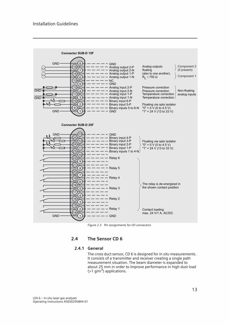
Figure 2.3 Pin assignments for I/O connectors
2.4 The Sensor CD 6
2.4.1 GeneralThe cross duct sensor, CD 6 is designed for in situ measurements. It consists of a transmitter and receiver creating a single path measurement situation. The beam diameter is expanded to about 25 mm in order to improve performance in high dust load (>1 g/m3) applications.
4
512
13
14
15
1
2
3
6
7
8
9
10
11
12
13
7
8
9
10
11
4
517
18
19
1
2
3
6
16
21
14
20
15
22
23
24
25
GND
Contact loadingmax. 24 V/1 A, AC/DC
The relay is de-energized inthe shown contact position
Floating via opto isolator"0" = 0 V (0 to 4.5 V)"1" = 24 V (13 to 33 V)
Binary inputs 1 to 4-NBinary input 1-PBinary input 2-PBinary input 3-PBinary input 4-PGND
GND
Relay 1
Relay 2
Relay 3
Relay 4
Relay 5
Relay 6
GND
Connector SUB-D 25F
Temperature correctionTemperature correction
Pressure correctionPressure correction
Analog outputs:floating(also to one another),RL ≤ 750 Ω
Non-floatinganalog inputs
GND
Analog output 2-P
GNDNC
GND
Analog output 1-NAnalog output 1-PAnalog output 2-N
Analog input 2-PAnalog input 2-NAnalog input 1-PAnalog input 1-NBinary input 6-PBinary input 5-PBinary inputs 5 to 6-N
GND
GND
GND
Connector SUB-D 15F
GND
Component 2(if present)
Component 1
Floating via opto isolator"0" = 0 V (0 to 4.5 V)"1" = 24 V (13 to 33 V)
LDS 6 – In-situ laser gas analyzerOperating instructions A5E00295894-01
13
Installation Guidelines
The transmitter includes a lens and a connection for the optical fiber located in the focal plane of the lens. The receiver contains a lens, a detector with preamplifier, driver electronics for the optical return signal, and a 24 VDC to ±15 VDC DC/DC-converter.
The laser light is coupled from the optical fiber in the transmitter to the transmitter lens and passes through the measurement vol-ume. The lens in the receiver focuses the incoming laser light on the detector where it is converted to an electrical signal. This sig-nal is amplified and converted to an optical signal and returned to the central unit LDS 6.
2.4.2 Mounting of Specific FlangesThere are three standard flanges available to mount the sensors for LDS 6:
1. DN65/PN6: The mounting of the sensor requires a DIN-flange (not delivered by Siemens Laser Analytics) with the dimen-sion DN65/PN6.
2. ANSI 4”/150lbf: The mounting of the sensor requires an ANSI flange (not delivered by Siemens Laser Analytics) with the dimension ANSI 4”/150lbf.
3. Motor wedge: The mounting of the sensor requires a specially designed flange and a special motor wedge (both delivered by Siemens Laser Analytics).
2.4.3 Installing and Aligning CD 6The installation of CD 6 is very straightforward and can be per-formed by the customer.
Mechanical InstallationThe transmitter and the receiver of CD 6 require a process flange as described in the above section. These have to be welded and aligned at the site before commissioning of LDS 6. Additionally, depending on application, one or two of the following might be needed:
• a supply of instrument air with 2000 – 8000 hPa pressure reg-ulation;
• 200 °C - 4000 hPa steam;
• electrical power for 370 W 1 phase electrical motor.
The instrument air is the most common way of keeping the wedge windows clean and should be connected using 6 mm (outer diameter) semi-rigid tubing.
LDS 6 – In-situ laser gas analyzerOperating instructions A5E00295894-01
14
Installation Guidelines
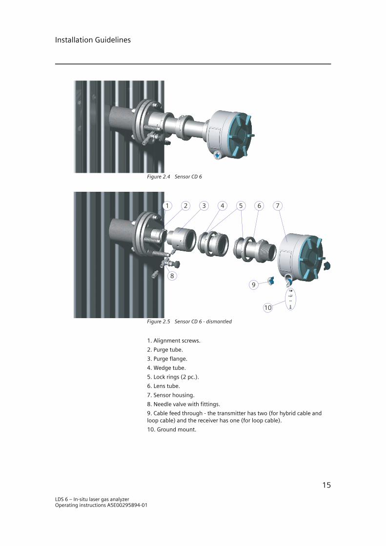
Figure 2.4 Sensor CD 6
Figure 2.5 Sensor CD 6 - dismantled
21 3 4 5 6 7
89
10
1. Alignment screws.
2. Purge tube.
3. Purge flange.
4. Wedge tube.
5. Lock rings (2 pc.).
6. Lens tube.
7. Sensor housing.
8. Needle valve with fittings.
9. Cable feed through - the transmitter has two (for hybrid cable and loop cable) and the receiver has one (for loop cable).
10. Ground mount.
LDS 6 – In-situ laser gas analyzerOperating instructions A5E00295894-01
15
Installation Guidelines
NOTEThe process flanges must be mounted parallel to each other and the maximum error angle is ±2 deg relative to the symmetrical axis of the two flanges (transmitter and receiver). It is also important that the sensor flanges are oriented in such a way that the spring loaded bolts are located in the lower section of the flange - see “Sensor CD 6” on page 15.
At installation of CD 6, the fiber end and the photo-detector have to be aligned to the optical axis of the sensor pair. Note that each sensor has an optical axis of its own which is its axis of symme-try. Normally the process flanges are mounted with an angle error. CD 6 is, however, equipped with a flange pair with a spher-ical interface. This is used when the sensor pair is aligned to each other, see “Alignment of the Sensors” on page 48. In this way an angle error of up to ±2° on each side can be adjusted for.
ConnectionsFour test points are available on the sensor card. The power and signal levels can be examined here using an oscilloscope or a multi-meter. Upon installation, the signal levels should be adjusted to be between 2 and 4 volts peak. This is done with the potentiometer on the detector card. After the signal level adjust-ment, the analyzer lockin-phase has to be adjusted as well. The potentiometer is factory-adjusted to minimum gain.
NOTEOnly trained installation personnel are allowed to adjust the gain level and lockin-phase for the application.
The powering of the receiver electronics is performed with a twisted pair copper cable delivering 24 VDC. This voltage feeds a DC/DC converter mounted on the sensor card which is able to give ±15 VDC and to handle 18 to 36 VDC on its input. This means that the system can handle large variations on the sensor voltage and thus will be very resistant to disturbances.
2.5 Dimensional Drawings
The central unit will fit in a standard 19” rack. The dimensions of it and the sensor CD 6 are shown in the following figures. Be sure to allow at least 50 cm (20”) behind the sensor for accessibility.
LDS 6 – In-situ laser gas analyzerOperating instructions A5E00295894-01
16

Installation Guidelines
Figure 2.6 Dimensional drawings of the central unit – LDS 6
s
LDS 6
35
1.5 4
28
440
465483
17
8
355432
483437
17
7
10
1.6
LDS 6 – In-situ laser gas analyzerOperating instructions A5E00295894-01
17

Installation Guidelines
Figure 2.7 Dimensional drawings of the sensors CD 3002Ex and CD 6
41
5
15
2
200
Customer flange
Top view
37
0 (
77
0, 1
17
0)
40
0 (
80
0, 1
20
0)
Ø 44.5
Customer tube
Purging tube
Customer flange
37
0 (
77
0, 1
17
0)
40
0 (
80
0, 1
20
0)
Ø 44.5
Customer tube
Purging tube
39
5
10
5
Ø163
LDS 6 – In-situ laser gas analyzerOperating instructions A5E00295894-01
18

Operation
Operation 33.1 General
Once the installation of the sensors at the measurement points is done and the connection via hybrid cables to the LDS 6 is estab-lished, the system is ready to be used. The functions in the LDS 6 are controlled through a keypad on the front of the panel. A 5” LCD screen is used to present the measurement values as well as the instrument’s graphical interface.
Figure 3.1 The keypad and the screen on LDS 6
1. Status line (can be parameterized using function 53). If a fault occurs during operation, the message ”Maintenance request” or ”Fault” appears in the status line depending on the impor-tance of the fault. This message is displayed alternately with the status messages.
2. Status display: LIM means: limit (alarm) signaling is idle and LIM means: limit (alarm) has been triggered.
3. Measured value.
LIM STO CTRL TR CODE
mg/Nm NH Ch1
%vol H O Ch1
mg/Nm NH Ch2
%vol H O Ch2
LIM STO CTRL TR CODE
11.1311.28
1 2 3
4 5 6
7 8 9
0
+/- CLEAR
ENTER
ESC
INFO
MEAS
2
3
3
2
12.5310.13
3
3
12
3
4 5
6
LDS 6 – In-situ laser gas analyzerOperating instructions A5E00295894-01
19
Operation
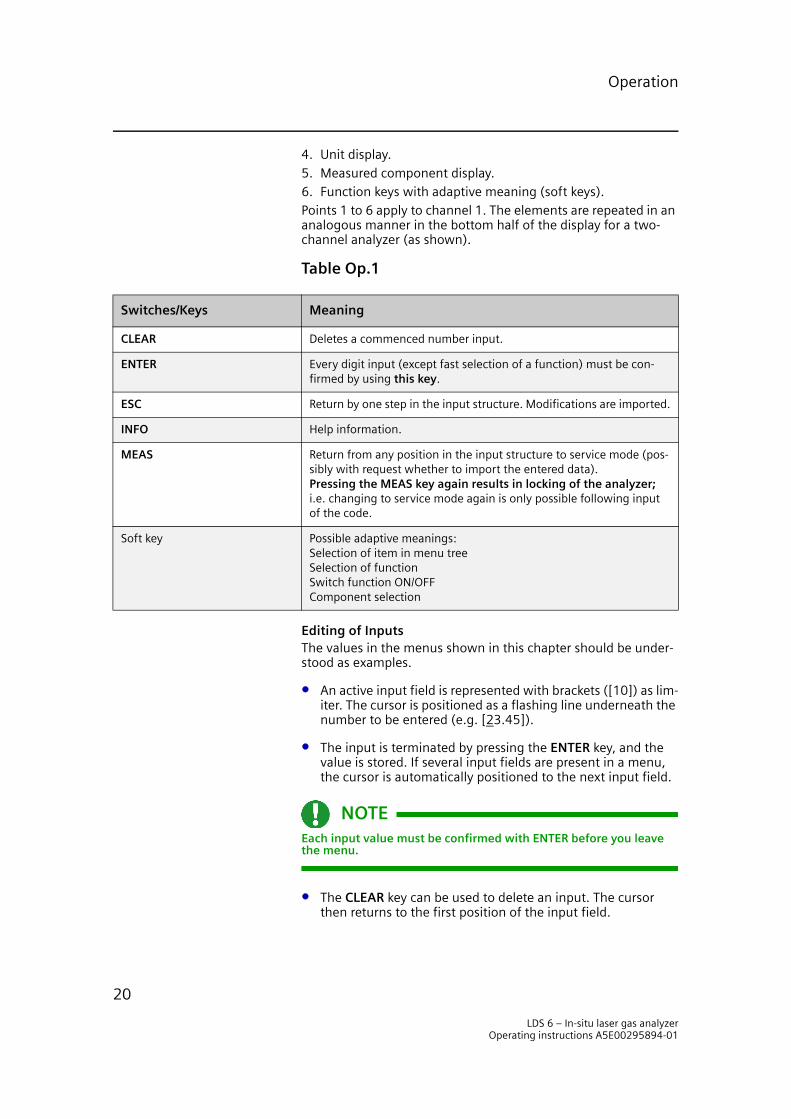
4. Unit display.5. Measured component display.6. Function keys with adaptive meaning (soft keys).Points 1 to 6 apply to channel 1. The elements are repeated in an analogous manner in the bottom half of the display for a two-channel analyzer (as shown).
Table Op.1
Editing of InputsThe values in the menus shown in this chapter should be under-stood as examples.
• An active input field is represented with brackets ([10]) as lim-iter. The cursor is positioned as a flashing line underneath the number to be entered (e.g. [23.45]).
• The input is terminated by pressing the ENTER key, and the value is stored. If several input fields are present in a menu, the cursor is automatically positioned to the next input field.
NOTEEach input value must be confirmed with ENTER before you leave the menu.
• The CLEAR key can be used to delete an input. The cursor then returns to the first position of the input field.
Switches/Keys Meaning
CLEAR Deletes a commenced number input.
ENTER Every digit input (except fast selection of a function) must be con-firmed by using this key.
ESC Return by one step in the input structure. Modifications are imported.
INFO Help information.
MEAS Return from any position in the input structure to service mode (pos-sibly with request whether to import the entered data).Pressing the MEAS key again results in locking of the analyzer;i.e. changing to service mode again is only possible following input of the code.
Soft key Possible adaptive meanings: Selection of item in menu treeSelection of functionSwitch function ON/OFFComponent selection
LDS 6 – In-situ laser gas analyzerOperating instructions A5E00295894-01
20
Operation
Graphic Styling Elements Switching function (ON status).
Switching function (OFF status, also status display in the sta-tus line).
Entry into a subsequent menu.
Triggering of a function.
Measuring mode: analyzer is coded.
Service mode: signals are activated according to functions 71 and 77.
NOTETo avoid static charges, the keyboard must only be used for servic-ing and input purposes.
3.2 Input sequence
The figure “Input sequence interacting with LDS 6” on page 22 shows the input sequence of LDS 6. The circled numbers marking certain steps in the input sequence can also be found in the text following the figure.
LDS 6 – In-situ laser gas analyzerOperating instructions A5E00295894-01
21

Operation
Figure 3.2 Input sequence interacting with LDS 6
LIM
STO
CTRL
TR
CODE
mg/Nm NH
ch1
%vol H O
ch1
mg/Nm NH
ch2
%vol H O
ch2
LIM
STO
CTRL
TR
CODE
11.13
63.28
2
33
2
63.28
11.13
Co
de
Ha
rd k
eys
Sta
rt f
rom
me
asu
rin
g m
od
e
On
ly f
ollo
win
g m
od
ific
ati
on
s
Inp
ut
of
pa
ssw
ord
Coding of analyzer
Mo
dif
ica
tio
ns
are
imp
ort
ed
Me
asu
rin
g m
od
e
Se
rvic
e m
od
e
Re
lay
"Fu
nct
ion
co
ntr
ol"
(CT
RL,
fu
nct
ion
71
)
Sto
re f
or
an
alo
g o
utp
ut
(fu
nct
ion
77
)
Ma
in M
en
u
Analyzer Status
Measuring Range
Parameters
Configuration
Calibration
To
Me
as.
Scr
ee
n
Accept Modifications?
No
Yes
Fu
nct
ion
Me
nu
--------------------
--------------------
--------------------
--------------------
--------------------
Fu
nct
ion
---------------------
---------------------
---------------------
---------------------
---------------------
So
ft k
eys
2
3
4
56
7
8
9
1
LDS 6 – In-situ laser gas analyzerOperating instructions A5E00295894-01
22

Operation
Entry into Main Menu for a 1- or 2-Channel System
Whilst in Measuring Mode, the component is shown on the right, with an arrow ( ). A soft key (1) is assigned to this spe-cific component and it is called by pressing it.
Entry into Main Menu for a 3-Channel System
The appearance of the screen menu varies depending on the number of channels and the number of measured components. For a 3-channel system the soft keys of the measuring screen are assigned to channels instead of measured components. If the channel has two components it is necessary to pass a second channel-specific measuring screen before entering the compo-nent-specific main menu.
Each channel can be operated independently.
Main MenuThe main menu consists of the five items shown in the adjacent screen.
Entering a SubmenuFollowing the selection of a submenu, you will be asked to enter a password for service mode 2 (exception: submenu ”Analyzer status” which requires no password and is thus freely-accessible).
The passwords for levels 1 and 2 are factory-set to the values ”111” and ”222” respectively.
LIM STO CTRL TR CODE
LIM STO CTRL TR CODE
11.13 %vol11.28 mg/Nm
Ch1
Ch2
Ch3
LIM STO CTRL TR CODE
10.13 %vol
3
12.53 mg/Nm3
15.13 %vol 5.28 mg/Nm3
%vol H O
mg/Nm NH11.2811.13
LIM STO CTRL TR CODE
Channel 1 3
3
2
Configuration
Parameters
Measuring Range
Calibration
Analyzer Status
Main Menu Ch1 NH3
Analyzer status No code
Calibration Access level 2
Measuring ranges Access level 1
Parameters Access level 1
Configuration Access level 2
LDS 6 – In-situ laser gas analyzerOperating instructions A5E00295894-01
23
Operation
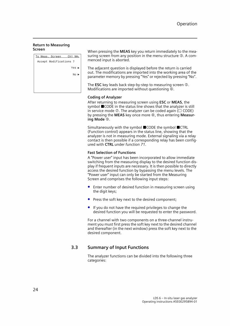
Return to Measuring Screen
When pressing the MEAS key you return immediately to the mea-suring screen from any position in the menu structure 3. A com-menced input is aborted.
The adjacent question is displayed before the return is carried out. The modifications are imported into the working area of the parameter memory by pressing “Yes” or rejected by pressing “No”.
The ESC key leads back step-by-step to measuring screen 5. Modifications are imported without questioning 6.
Coding of AnalyzerAfter returning to measuring screen using ESC or MEAS, the symbol CODE in the status line shows that the analyzer is still in service mode 7. The analyzer can be coded again ( CODE) by pressing the MEAS key once more 8, thus entering Measur-ing Mode 9.
Simultaneously with the symbol CODE the symbol CTRL (Function control) appears in the status line, showing that the analyzer is not in measuring mode. External signaling via a relay contact is then possible if a corresponding relay has been config-ured with CTRL under function 71.
Fast Selection of FunctionsA ”Power user” input has been incorporated to allow immediate switching from the measuring display to the desired function dis-play if frequent inputs are necessary. It is then possible to directly access the desired function by bypassing the menu levels. The ”Power user” input can only be started from the Measuring Screen and comprises the following input steps:
• Enter number of desired function in measuring screen using the digit keys;
• Press the soft key next to the desired component;
• If you do not have the required privileges to change the desired function you will be requested to enter the password.
For a channel with two components on a three-channel instru-ment you must first press the soft key next to the desired channel and thereafter (in the next window) press the soft key next to the desired component.
3.3 Summary of Input Functions
The analyzer functions can be divided into the following three categories:
No
Yes
Accept Modifications ?
To Meas. Screen Ch1 NH3
LDS 6 – In-situ laser gas analyzerOperating instructions A5E00295894-01
24
Operation
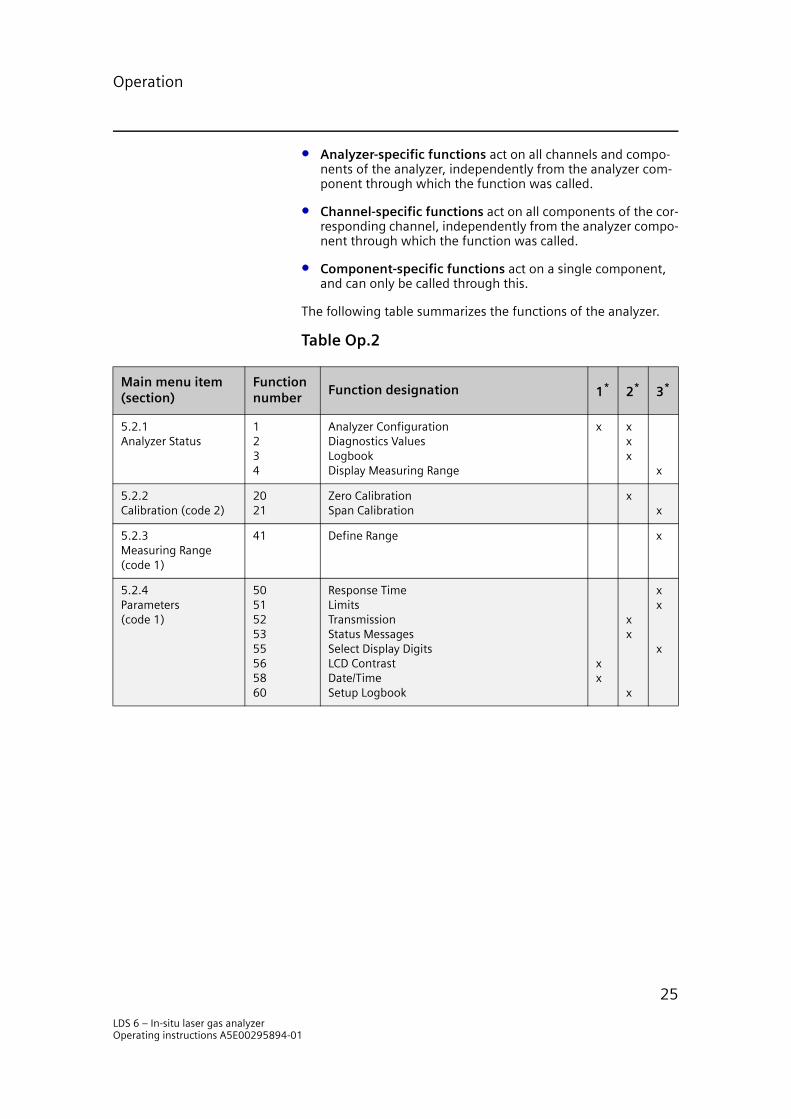
• Analyzer-specific functions act on all channels and compo-nents of the analyzer, independently from the analyzer com-ponent through which the function was called.
• Channel-specific functions act on all components of the cor-responding channel, independently from the analyzer compo-nent through which the function was called.
• Component-specific functions act on a single component, and can only be called through this.
The following table summarizes the functions of the analyzer.
Table Op.2
Main menu item (section)
Function number
Function designation 1* 2* 3*
5.2.1Analyzer Status
1234
Analyzer ConfigurationDiagnostics ValuesLogbookDisplay Measuring Range
x xxx
x
5.2.2Calibration (code 2)
2021
Zero CalibrationSpan Calibration
xx
5.2.3Measuring Range(code 1)
41 Define Range x
5.2.4Parameters(code 1)
5051525355565860
Response TimeLimitsTransmissionStatus MessagesSelect Display DigitsLCD ContrastDate/TimeSetup Logbook
xx
xx
x
xx
x
LDS 6 – In-situ laser gas analyzerOperating instructions A5E00295894-01
25
Operation
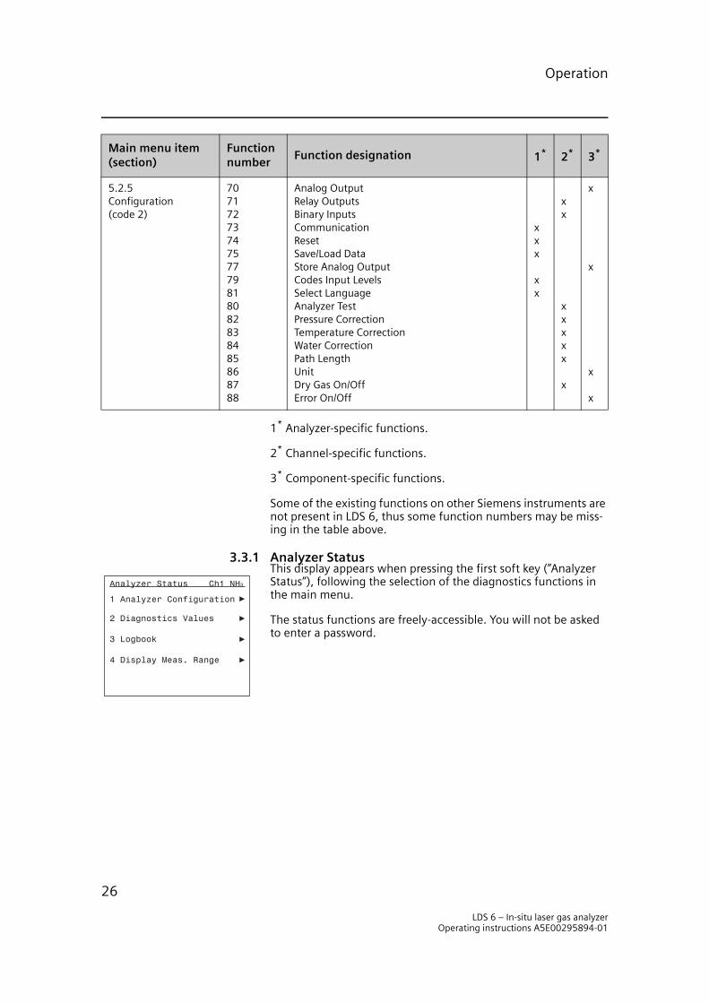
1* Analyzer-specific functions.
2* Channel-specific functions.
3* Component-specific functions.
Some of the existing functions on other Siemens instruments are not present in LDS 6, thus some function numbers may be miss-ing in the table above.
3.3.1 Analyzer StatusThis display appears when pressing the first soft key (”Analyzer Status”), following the selection of the diagnostics functions in the main menu.
The status functions are freely-accessible. You will not be asked to enter a password.
5.2.5Configuration(code 2)
7071727374757779818082838485868788
Analog OutputRelay OutputsBinary InputsCommunicationResetSave/Load DataStore Analog OutputCodes Input LevelsSelect LanguageAnalyzer TestPressure CorrectionTemperature CorrectionWater CorrectionPath LengthUnitDry Gas On/OffError On/Off
xxx
xx
xx
xxxxx
x
x
x
x
x
Main menu item (section)
Function number
Function designation 1* 2* 3*
4 Display Meas. Range
3 Logbook
2 Diagnostics Values
1 Analyzer Configuration
Analyzer Status Ch1 NH3
LDS 6 – In-situ laser gas analyzerOperating instructions A5E00295894-01
26
Operation
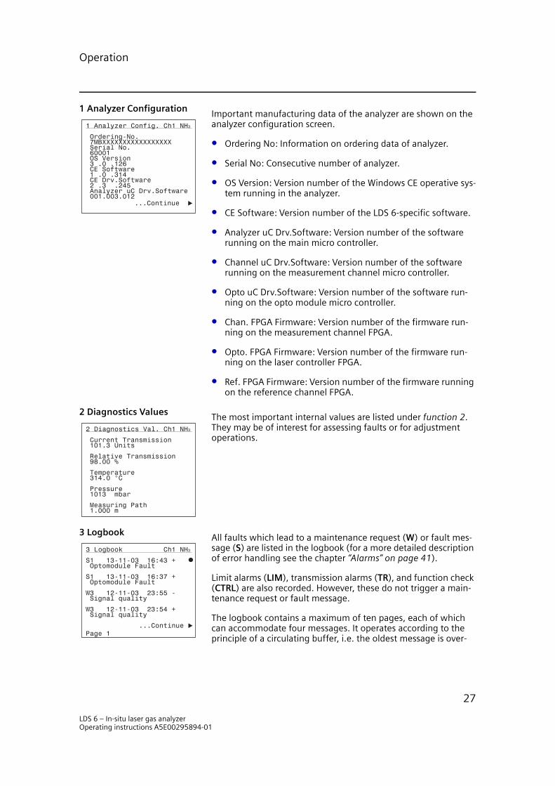
1 Analyzer ConfigurationImportant manufacturing data of the analyzer are shown on the analyzer configuration screen.
• Ordering No: Information on ordering data of analyzer.
• Serial No: Consecutive number of analyzer.
• OS Version: Version number of the Windows CE operative sys-tem running in the analyzer.
• CE Software: Version number of the LDS 6-specific software.
• Analyzer uC Drv.Software: Version number of the software running on the main micro controller.
• Channel uC Drv.Software: Version number of the software running on the measurement channel micro controller.
• Opto uC Drv.Software: Version number of the software run-ning on the opto module micro controller.
• Chan. FPGA Firmware: Version number of the firmware run-ning on the measurement channel FPGA.
• Opto. FPGA Firmware: Version number of the firmware run-ning on the laser controller FPGA.
• Ref. FPGA Firmware: Version number of the firmware running on the reference channel FPGA.
2 Diagnostics ValuesThe most important internal values are listed under function 2. They may be of interest for assessing faults or for adjustment operations.
3 LogbookAll faults which lead to a maintenance request (W) or fault mes-sage (S) are listed in the logbook (for a more detailed description of error handling see the chapter “Alarms” on page 41).
Limit alarms (LIM), transmission alarms (TR), and function check (CTRL) are also recorded. However, these do not trigger a main-tenance request or fault message.
The logbook contains a maximum of ten pages, each of which can accommodate four messages. It operates according to the principle of a circulating buffer, i.e. the oldest message is over-
1 Analyzer Config. Ch1 NH3
001.003.012 Analyzer uC Drv.Software 2 .3 .245 CE Drv.Software 1 .0 .314 CE Software 3 .0 .126 OS Version 60001 Serial No. 7MBXXXXXXXXXXXXXXXXX Ordering-No.
...Continue
2 Diagnostics Val. Ch1 NH3
1.000 m Measuring Path
1013 mbar Pressure
314.0 °C Temperature
98.00 % Relative Transmission
101.3 Units Current Transmission
3 Logbook Ch1 NH3
...Continue Page 1
Signal qualityW3 12-11-03 23:54 +
Signal qualityW3 12-11-03 23:55 -
Optomodule Fault S1 13-11-03 16:37 +
Optomodule FaultS1 13-11-03 16:43 +
LDS 6 – In-situ laser gas analyzerOperating instructions A5E00295894-01
27

Operation
written when all ten pages are full (40 messages). Fault mes-sages are not deleted if they have not been acknowledged.
The logbook entries can be deleted or blocked (function 60), or also switched off individually (function 87).
NOTEIf a fault occurs when the error message is switched off by function 87, there is no reaction at the interface. This applies to the analog as well as to the relay outputs.
4 Display Measuring Ranges
The measuring range is listed using function 4. However, it can-not be modified in this menu.
3.3.2 CalibrationThe LDS 6 is calibrated when delivered and does not normally require on site recalibration; however, if this should be necessary the procedure should only be carried out by skilled and trained personnel. Please consult Siemens Laser Analytics if recalibration is needed.
20 Zero CalibrationWhen zero calibration is triggered the current measurement value is stored. This value will thereafter always be subtracted from the measurement signal.
4 Disp. Meas.Range Ch1 NH3
0.00 100.0 mg/Nm3 Start End value
Calibrate
Zero Calibration Active
20 Zero Calib. Ch1 NH3
Act. Val. 0.12 mg/Nm3
LDS 6 – In-situ laser gas analyzerOperating instructions A5E00295894-01
28

Operation
21 Span CalibrationThis display lists the set point and the current value.
The calibration is triggered by pressing the third soft key. The cur-rent value is then set to coincide with the set point.
3.3.3 Measuring Range41 Define Range
It is possible to define a measuring range whose start-of-scale value is assigned to the bottom value (4 mA) and whose full-scale value is assigned to the top value (20 mA) of the analog output.
3.3.4 ParametersThis display, with the selection of the parameter functions 50 to 53 appears following the selection of the parameter functions in the main menu by pressing the fourth soft key (”Parameters”). You can branch to the parameter functions 54 to 60 by pressing the fifth soft key (...Continue).
50 Response TimeThis function can be used to set various time constants to reduce the noise superimposed on the measured value.
Act. Val. 288.1 mg/Nm
Setpoint 293.0 mg/Nm
21 Span Calib. Ch1 NH3
3
Calibrate
3
41 Define Range Ch1 NH3
3 0.000 100.0 mg/Nm Start Value End Value
Parameters Ch1 NH3
...Continue
53 Status Messages
52 Transmission
51 Limits
50 Response Time
Value: 63.28 mg/Nm
50 Response Time Ch1 NH3
3 Actual Measured
[5.000] Seconds
LDS 6 – In-situ laser gas analyzerOperating instructions A5E00295894-01
29

Operation
51 LimitsThe limit alarm is triggered when the value of a component exceeds the permissible range set in this screen. The alarm can be turned off here.
The limit alarm is displayed on the status line if this has been set up by function 53. The alarm is also signaled by a relay if this has been set up by function 71. The triggering of the transmission alarm is registered in the logbook (function 3).
52 TransmissionThe transmission alarm is triggered when the transmission is out-side a permissible range. The lower alarm level of the transmis-sion for a channel is set as a percentage of the nominal transmis-sion value, where the nominal value is registered as the fourth soft key is pressed. The upper alarm level is set to a fixed value and cannot be changed by the user.
The transmission alarm is displayed on the status line if this has been set up by function 53. The alarm is also signaled by a relay if this has been set up by function 71. The triggering of the trans-mission alarm is registered in the logbook (function 3).
53 Status MessagesThis function can be used to display - within the status line - up to four different status which can be assumed by the analyzer.
Table Op.3
The type of status ”Code” is always present in the status line.
Upper Limit[30.00] mg/Nm
51 Limits Ch1 NH3
Lower Limit 0.00 mg/Nm
3
3
Limit Alarm On/Off
Set Nominal Value
52 Transmission Ch1 NH3
Current 285.0 Units
Nominal 301.2 Units
Alarm Level[5 ] %
Transm. Alarm On/Off
Relative 84.93 %
53 Status Messages Ch1 NH3
[CTRL] Display Func. Control
[LIM] Display Limits
[STO] Display Stored Value
Display Transm. Limits [TR]
Function Status
STO: Stored Value Analog output connected to memory (see also function 77).
LIM: Limit Upward or downward violation of limit (see also function 51).
CTRL: Function Control Start-up mode - Service mode.
TR: Transmission Upward or downward violation of transmission limit (see also func-tion 52).
LDS 6 – In-situ laser gas analyzerOperating instructions A5E00295894-01
30

Operation
55 Select DigitsThis function allows you to suppress the output of negative val-ues on the measuring screen. It is also possible to select the num-ber of decimal digits. The number of digits, including the decimal point, is always five when setting the function to automatic.
56 LCD ContrastYou can adjust the display contrast using this function.
If the contrast is wrongly adjusted you can re-establish the fac-tory settings by pressing the third soft key (”Basic setting”).
It is additionally possible to carry out an LCD test by pressing the fourth soft key (”Test”). Various test displays are then shown in succession. The test can be stopped by pressing ESC.
If the LCD contrast is extremely maladjusted, and if the analyzer is in measuring mode, you can re-establish the basic setting by pressing the following key sequence: 8888 ENTER
58 Date/TimeThe analyzer has a system clock which is not protected against power failure (not a real-time clock). The clock is set at 01-01-00 00:00 when the analyzer is started.
This function allows you to exactly set the date and time. This is particularly important to be able to assign a specific point in time to faults stored in the logbook. It can be of advantage when trou-bleshooting.
An editing field appears when you call the function in which you can enter day, month and year as ”New date”. Hours (24-hour system) and minutes are entered as ”New time”.
The set data are imported when you press the third soft key (”Set Clock”). The data then appear as an active display at the bottom of the screen.
NOTEThe date and time must be reset in case of a power failure.
Digits After Automatic
55 Select Digits Ch1 NH3
Values Supress Negative
Decimal Point
Brighter
Test
56 LCD Contrast Ch1 NH3
Basic Setting
Darker
New Date(dd-mm-yy;24h/day)
58 Date/Time Ch1 NH3
01-04-2004 14:44
Actual Date Actual Time
Set Clock
14:44New Time:
[01-04-04]
LDS 6 – In-situ laser gas analyzerOperating instructions A5E00295894-01
31
Operation
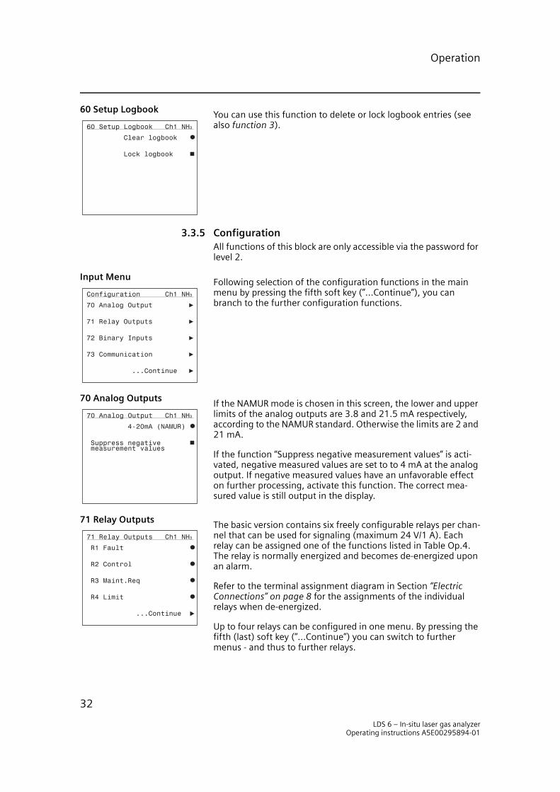
60 Setup LogbookYou can use this function to delete or lock logbook entries (see also function 3).
3.3.5 ConfigurationAll functions of this block are only accessible via the password for level 2.
Input MenuFollowing selection of the configuration functions in the main menu by pressing the fifth soft key (”...Continue”), you can branch to the further configuration functions.
70 Analog OutputsIf the NAMUR mode is chosen in this screen, the lower and upper limits of the analog outputs are 3.8 and 21.5 mA respectively, according to the NAMUR standard. Otherwise the limits are 2 and 21 mA.
If the function “Suppress negative measurement values” is acti-vated, negative measured values are set to to 4 mA at the analog output. If negative measured values have an unfavorable effect on further processing, activate this function. The correct mea-sured value is still output in the display.
71 Relay OutputsThe basic version contains six freely configurable relays per chan-nel that can be used for signaling (maximum 24 V/1 A). Each relay can be assigned one of the functions listed in Table Op.4. The relay is normally energized and becomes de-energized upon an alarm.
Refer to the terminal assignment diagram in Section “Electric Connections” on page 8 for the assignments of the individual relays when de-energized.
Up to four relays can be configured in one menu. By pressing the fifth (last) soft key (”...Continue”) you can switch to further menus - and thus to further relays.
60 Setup Logbook Ch1 NH3
Lock logbook
Clear logbook
Configuration Ch1 NH3
...Continue
73 Communication
72 Binary Inputs
71 Relay Outputs
70 Analog Output
70 Analog Output Ch1 NH3
measurement values Suppress negative
4-20mA (NAMUR)
71 Relay Outputs Ch1 NH3
...Continue
R4 Limit
R3 Maint.Req
R2 Control
R1 Fault
LDS 6 – In-situ laser gas analyzerOperating instructions A5E00295894-01
32

Operation
NOTEEvery change to the configuration of the relay outputs should always be stored in the user data memory using function 75. If this is not done, there is a risk that a previous (undesired) configuration is called when selecting “Load user data”.
Table Op.4 Relay Assignments
72 Binary InputsYou can freely configure the six floating binary inputs [”0” = 0 V (0...4.5 V); ”1” = 24 V (13...33 V)] available in the basic version.
You can assign one of the control functions listed in Table Op. 5 to each input. The binary input should normally be energized. De-energizing the binary input will result in signaling of a fault.
Refer to Section “Electric Connections” on page 8” for the assign-ments of the individual inputs. Up to four relays can be config-ured in one menu. Switching to further menus - and thus to fur-ther relays - is always carried out by pressing the fifth (last) soft key (”...Continue”).
NOTEEvery change to the configuration of the binary inputs should always be stored in the user data memory using function 75. If this is not done, there is a risk that a previous (undesired) configuration is called when selecting ”Load user data”.
Function Remarks
Vacant Relay is permanently de-energized.
Fault signaling for faults specified in Operation chapter.
Maintenance Request signaling for Maintenance Requests specified in Operation chapter.
Function Control (CTRL) signaling when analyzer is in start-up mode or in service mode (coded).
Transmission Limit Alarm (TR) Upward or downward violation of transmission limit (see also func-tion 52).
Limit Alarm (LIM) Upward or downward violation of limit (see also function 51).
Stored Value (STO) Relay may be de-energized simultaneously with fault, transmission alarm or function control depending on the configuration of function 77.
72 Binary Inputs Ch1 NH3
...Continue
B4 Ext. Maint.Req. Temp.
B3 Ext. Fault Purging
B2 Ext. Fault Prs.
B1 Ext. Fault Temp.
LDS 6 – In-situ laser gas analyzerOperating instructions A5E00295894-01
33
Operation
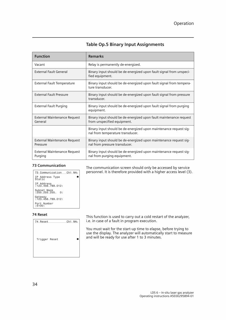
Table Op.5 Binary Input Assignments
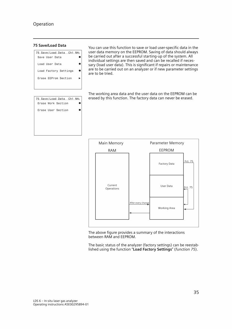
73 CommunicationThe communication screen should only be accessed by service personnel. It is therefore provided with a higher access level (3).
74 ResetThis function is used to carry out a cold restart of the analyzer, i.e. in case of a fault in program execution.
You must wait for the start-up time to elapse, before trying to use the display. The analyzer will automatically start to measure and will be ready for use after 1 to 3 minutes.
Function Remarks
Vacant Relay is permanently de-energized.
External Fault General Binary input should be de-energized upon fault signal from unspeci-fied equipment.
External Fault Temperature Binary input should be de-energized upon fault signal from tempera-ture transducer.
External Fault Pressure Binary input should be de-energized upon fault signal from pressure transducer.
External Fault Purging Binary input should be de-energized upon fault signal from purging equipment.
External Maintenance Request General
Binary input should be de-energized upon fault maintenance request from unspecified equipment.
Binary input should be de-energized upon maintenance request sig-nal from temperature transducer.
External Maintenance Request Pressure
Binary input should be de-energized upon maintenance request sig-nal from pressure transducer.
External Maintenance Request Purging
Binary input should be de-energized upon maintenance request sig-nal from purging equipment.
73 Communication Ch1 NH3
:5100:Port Number
:123.456.789.012:Gateway
:255.255.255. 0:Subnet Mask
:123.456.789.012:IP Address
StaticIP Address Type
74 Reset Ch1 NH3
Trigger Reset
LDS 6 – In-situ laser gas analyzerOperating instructions A5E00295894-01
34
Operation
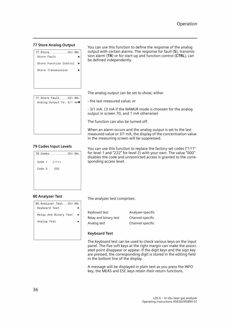
75 Save/Load DataYou can use this function to save or load user-specific data in the user data memory on the EEPROM. Saving of data should always be carried out after a successful starting-up of the system. All individual settings are then saved and can be recalled if neces-sary (load user data). This is significant if repairs or maintenance are to be carried out on an analyzer or if new parameter settings are to be tried.
The working area data and the user data on the EEPROM can be erased by this function. The factory data can never be erased.
The above figure provides a summary of the interactions between RAM and EEPROM.
The basic status of the analyzer (factory settings) can be reestab-lished using the function “Load Factory Settings” (function 75).
75 Save/Load Data Ch1 NH3
Load Factory Settings
Load User Data
Save User Data
Erase EEProm Section
75 Save/Load Data Ch1 NH3
Erase User Section
Erase Work Section
Main Memory
RAM EEPROM
Parameter Memory
CurrentOperations
Factory Data
User Data
Working Area
Fct. 75
Fct. 75
After every change
LDS 6 – In-situ laser gas analyzerOperating instructions A5E00295894-01
35
Operation
77 Store Analog OutputYou can use this function to define the response of the analog output with certain alarms. The response for fault (S), transmis-sion alarm (TR) or for start-up and function control (CTRL), can be defined independently.
The analog output can be set to show; either
- the last measured value; or
- 3/1 mA. (3 mA if the NAMUR mode is choosen for the analog output in screen 70, and 1 mA otherwise)
The function can also be turned off.
When an alarm occurs and the analog output is set to the last measured value or 3/1 mA, the display of the concentration value in the measuring screen will be suppressed.
79 Codes Input LevelsYou can use this function to replace the factory-set codes (”111” for level 1 and ”222” for level 2) with your own. The value ”000” disables the code and unrestricted access is granted to the corre-sponding access level.
80 Analyzer TestThe analyzer test comprises:
Keyboard Test
The keyboard test can be used to check various keys on the input panel. The five soft keys at the right margin can make the associ-ated point disappear or appear. If the digit keys and the sign key are pressed, the corresponding digit is stored in the editing field in the bottom line of the display.
A message will be displayed in plain text as you press the INFO key; the MEAS and ESC keys retain their return functions.
77 Store Ch1 NH3
Store Transmission
Store Function Control
Store Fault
77 Store Fault Ch1 NH3
Analog Output To: 3/1 mA
79 Codes Ch1 NH3
Code 2 222
Code 1 [111]
80 Analyzer Test Ch1 NH3
Analog Test
Relay And Binary Test
Keyboard Test
Keyboard test Analyzer-specific
Relay and binary test Channel-specific
Analog test Channel-specific
LDS 6 – In-situ laser gas analyzerOperating instructions A5E00295894-01
36
Operation
Relay and Binary Test
NOTEFirst remove data plugs.
The first display shows 6 of the relay and binary channels. Indi-vidual relays can be activated using the relay test. This is carried out by using the input field. A ”1” makes the relay pull up, a ”0” makes it return to the de-energized state. Digits other than 0 and 1 are not accepted by the input field. After leaving function 80, the relays reassume their former status, prior to selection of the relay and binary test. The column ”Binary” shows the current sta-tus of the binary inputs in this display.
Analog Test
The analog test can be used to parameter the analog output with a constant current of 0 - 24 mA for test purposes. The analog input permanently shows the input currents in mA.
81 Select LanguageYou can use this function to switch the analyzer to a different dia-logue language.
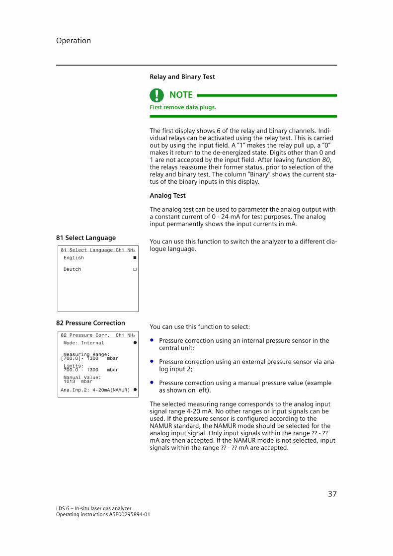
82 Pressure CorrectionYou can use this function to select:
• Pressure correction using an internal pressure sensor in the central unit;
• Pressure correction using an external pressure sensor via ana-log input 2;
• Pressure correction using a manual pressure value (example as shown on left).
The selected measuring range corresponds to the analog input signal range 4-20 mA. No other ranges or input signals can be used. If the pressure sensor is configured according to the NAMUR standard, the NAMUR mode should be selected for the analog input signal. Only input signals within the range ?? - ?? mA are then accepted. If the NAMUR mode is not selected, input signals within the range ?? - ?? mA are accepted.
81 Select Language Ch1 NH3
Deutch
English
Mode: Internal
82 Pressure Corr. Ch1 NH3
1013 mbar Manual Value:
700.0 - 1300 mbar Limits:
[700.0]- 1300 mbar Measuring Range:
Ana.Inp.2: 4-20mA(NAMUR)
LDS 6 – In-situ laser gas analyzerOperating instructions A5E00295894-01
37

Operation
The limits should normally mark the interval in which pressure compensation is possible. If the pressure signal exceeds the spec-ified limits this will be reported as a fault on the instrument.
The parameters for the pressure correction in the corresponding factory function are component-specific. Selection of the pres-sure mode in function 82 is channel-specific.
It is possible to switch off the pressure correction.
83 Temperature CorrectionYou can use this function to select
• Temperature correction using an external temperature sensor via analog input 1 (example as shown on left);
• Temperature correction using a manual temperature value;
• Temperature correction using the internally calculated pro-cess temperature. This is only possible if the LDS 6 is set up to measure the temperature at the measuring point.
The parameters for the temperature correction in the corre-sponding factory function are component-specific. Selection of the temperature mode in function 83 is channel-specific.
The selected measuring range corresponds to the analog input signal range 4-20 mA. No other ranges or input signals can be used. If the pressure sensor is configured according to the NAMUR standard, the NAMUR mode should be selected for the analog input signal. Only input signals within the range 3.8 - 20 mA are then accepted. If the NAMUR mode is not selected, input signals within the range 2 - 21 mA are accepted.
The limits should normally mark the interval in which tempera-ture compensation is possible. If the temperature signal exceeds the specified limits this will be reported as a fault on the instru-ment.
It is possible to switch off the temperature correction.
84 Water CorrectionIn this screen it is possible to activate or deactivate the water cor-rection function. Water correction is necessary for some applica-tions to correct for influences of water vapor on other gases. The function should be turned off at calibration to dry gas.
If water is not calculated by the instrument itself, a water con-centration value should be manually entered here.
Mode: Manual
83 Temp. Corr. Ch1 NH3
300.0 °C Manual Value:
0.00 - 1000 °C Limits:
[0.00 ]- 400.0 °C Measuring Range:
Ana.Inp.1: 4-20mA(NAMUR)
Water Correction Active
84 Water Corr. Ch1 NH3
23.0 %vol Manual Value:
LDS 6 – In-situ laser gas analyzerOperating instructions A5E00295894-01
38

Operation
85 Path LengthThe length of the measuring path for the specific channel should be set in this screen.
86 UnitThe unit for a specific component can be set in this screen. Possi-ble units for concentrations are: ppm, %vol, mg/Nm3 EU (metric standard) or mg/Nm3 US (American standard). Possible units for temperature are: °C, °F or K.
87 Dry Gas On/OffIt is possible to display the dry value of the concentration, i.e. the calculated concentration when the volume of water vapor has been subtracted from the total volume of gas. This function can be activated in the adjacent display.
88 Error On/Offsignaling of maintenance requests and faults (xxx see Tables 6.3 and 6.4) can be switched off individually using this function so that neither an entry in the logbook, nor a status signal or exter-nal signaling take place.
Error messages which do not apply to this channel are identified by the absence of text following the error number.
85 Path Length Ch1 NH3
[1.000] m
86 Unit Ch1 NH3
mg/Nm EU 3
87 Dry Gas On/Off Ch1 NH3
Dry Gas
88 Error On/Off Ch1 NH3
...Continue
Compensation Temp. Limit S4
Signal Quality Fault S3
Laser Current Fault S2
Optomodule Fault S1
LDS 6 – In-situ laser gas analyzerOperating instructions A5E00295894-01
39

Operation
LDS 6 – In-situ laser gas analyzerOperating instructions A5E00295894-01
40
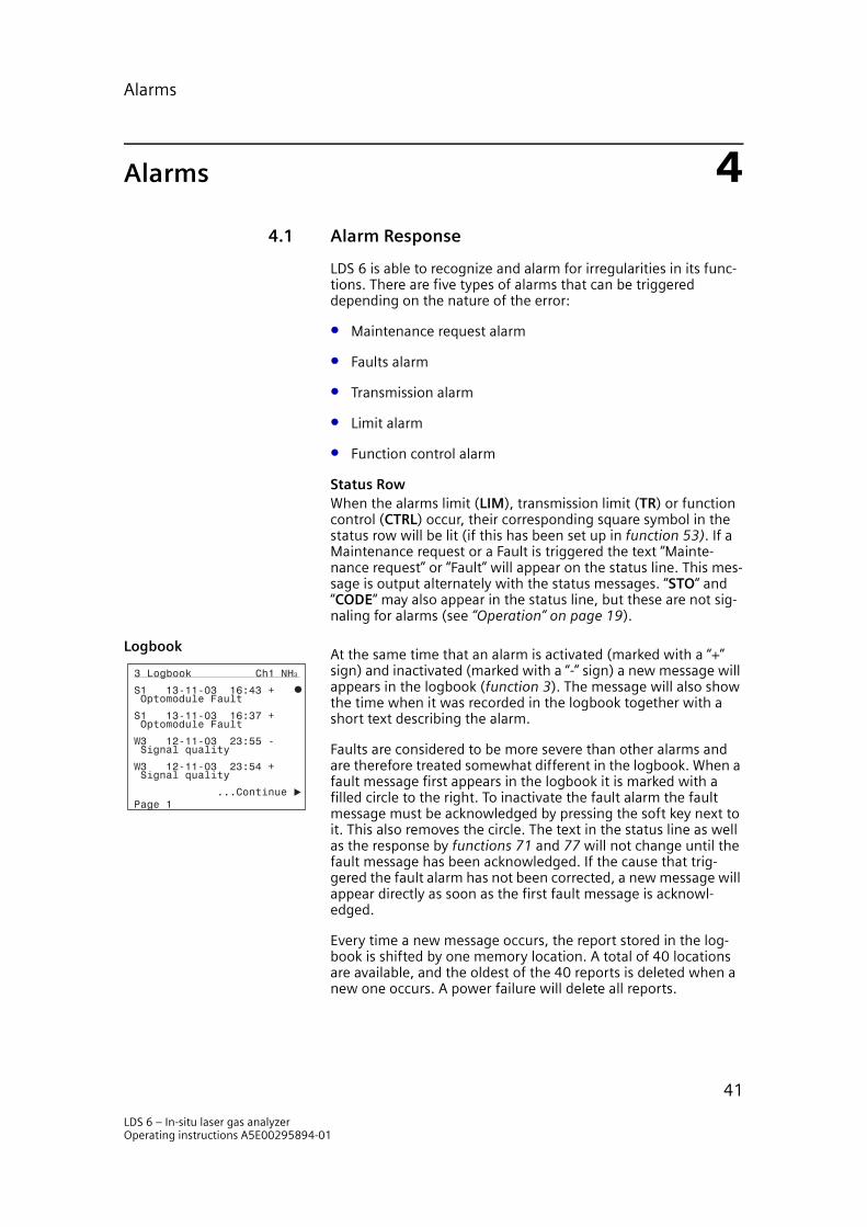
Alarms
Alarms 44.1 Alarm Response
LDS 6 is able to recognize and alarm for irregularities in its func-tions. There are five types of alarms that can be triggered depending on the nature of the error:
• Maintenance request alarm
• Faults alarm
• Transmission alarm
• Limit alarm
• Function control alarm
Status RowWhen the alarms limit (LIM), transmission limit (TR) or function control (CTRL) occur, their corresponding square symbol in the status row will be lit (if this has been set up in function 53). If a Maintenance request or a Fault is triggered the text “Mainte-nance request” or “Fault” will appear on the status line. This mes-sage is output alternately with the status messages. “STO“ and “CODE“ may also appear in the status line, but these are not sig-naling for alarms (see “Operation” on page 19).
LogbookAt the same time that an alarm is activated (marked with a “+” sign) and inactivated (marked with a “-” sign) a new message will appears in the logbook (function 3). The message will also show the time when it was recorded in the logbook together with a short text describing the alarm.
Faults are considered to be more severe than other alarms and are therefore treated somewhat different in the logbook. When a fault message first appears in the logbook it is marked with a filled circle to the right. To inactivate the fault alarm the fault message must be acknowledged by pressing the soft key next to it. This also removes the circle. The text in the status line as well as the response by functions 71 and 77 will not change until the fault message has been acknowledged. If the cause that trig-gered the fault alarm has not been corrected, a new message will appear directly as soon as the first fault message is acknowl-edged.
Every time a new message occurs, the report stored in the log-book is shifted by one memory location. A total of 40 locations are available, and the oldest of the 40 reports is deleted when a new one occurs. A power failure will delete all reports.
3 Logbook Ch1 NH3
...Continue Page 1
Signal qualityW3 12-11-03 23:54 +
Signal qualityW3 12-11-03 23:55 -
Optomodule Fault S1 13-11-03 16:37 +
Optomodule FaultS1 13-11-03 16:43 +
LDS 6 – In-situ laser gas analyzerOperating instructions A5E00295894-01
41
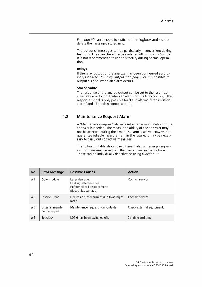
Alarms
Function 60 can be used to switch off the logbook and also to delete the messages stored in it.
The output of messages can be particularly inconvenient during test runs. They can therefore be switched off using function 87. It is not recommended to use this facility during normal opera-tion.
RelaysIf the relay output of the analyzer has been configured accord-ingly (see also “71 Relay Outputs” on page 32), it is possible to output a signal when an alarm occurs.
Stored ValueThe response of the analog output can be set to the last mea-sured value or to 3 mA when an alarm occurs (function 77). This response signal is only possible for “Fault alarm”, “Transmission alarm” and “Function control alarm”.
4.2 Maintenance Request Alarm
A “Maintenance request” alarm is set when a modification of the analyzer is needed. The measuring ability of the analyzer may not be affected during the time this alarm is active. However, to guarantee reliable measurement in the future, it may be neces-sary to carry out corrective measures.
The following table shows the different alarm messages signal-ing for maintenance request that can appear in the logbook. These can be individually deactivated using function 87.
No. Error Message Possible Causes Action
W1 Opto module Laser damage.Leaking reference cell.Reference cell displacement.Electronics damage.
Contact service.
W2 Laser current Decreasing laser current due to aging of laser.
Contact service.
W3 External mainte-nance request
Maintenance request from outside. Check external equipment.
W4 Set clock LDS 6 has been switched off. Set date and time.
LDS 6 – In-situ laser gas analyzerOperating instructions A5E00295894-01
42
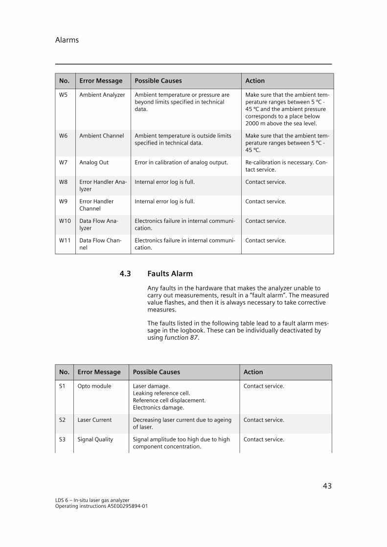
Alarms
4.3 Faults Alarm
Any faults in the hardware that makes the analyzer unable to carry out measurements, result in a “fault alarm”. The measured value flashes, and then it is always necessary to take corrective measures.
The faults listed in the following table lead to a fault alarm mes-sage in the logbook. These can be individually deactivated by using function 87.
W5 Ambient Analyzer Ambient temperature or pressure are beyond limits specified in technical data.
Make sure that the ambient tem-perature ranges between 5 °C - 45 °C and the ambient pressure corresponds to a place below 2000 m above the sea level.
W6 Ambient Channel Ambient temperature is outside limits specified in technical data.
Make sure that the ambient tem-perature ranges between 5 °C - 45 °C.
W7 Analog Out Error in calibration of analog output. Re-calibration is necessary. Con-tact service.
W8 Error Handler Ana-lyzer
Internal error log is full. Contact service.
W9 Error Handler Channel
Internal error log is full. Contact service.
W10 Data Flow Ana-lyzer
Electronics failure in internal communi-cation.
Contact service.
W11 Data Flow Chan-nel
Electronics failure in internal communi-cation.
Contact service.
No. Error Message Possible Causes Action
No. Error Message Possible Causes Action
S1 Opto module Laser damage.Leaking reference cell.Reference cell displacement.Electronics damage.
Contact service.
S2 Laser Current Decreasing laser current due to ageing of laser.
Contact service.
S3 Signal Quality Signal amplitude too high due to high component concentration.
Contact service.
LDS 6 – In-situ laser gas analyzerOperating instructions A5E00295894-01
43
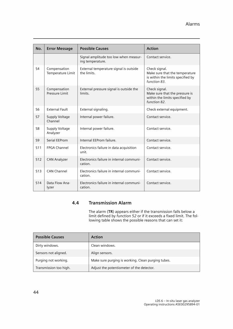
Alarms
4.4 Transmission Alarm
The alarm (TR) appears either if the transmission falls below a limit defined by function 52 or if it exceeds a fixed limit. The fol-lowing table shows the possible reasons that can set it:
Signal amplitude too low when measur-ing temperature.
Contact service.
S4 Compensation Temperature Limit
External temperature signal is outside the limits.
Check signal.Make sure that the temperature is within the limits specified by function 83.
S5 Compensation Pressure Limit
External pressure signal is outside the limits.
Check signal.Make sure that the pressure is within the limits specified by function 82.
S6 External Fault External signaling. Check external equipment.
S7 Supply Voltage Channel
Internal power failure. Contact service.
S8 Supply Voltage Analyzer
Internal power failure. Contact service.
S9 Serial EEProm Internal EEProm failure. Contact service.
S11 FPGA Channel Electronics failure in data acquisition unit.
Contact service.
S12 CAN Analyzer Electronics failure in internal communi-cation.
Contact service.
S13 CAN Channel Electronics failure in internal communi-cation.
Contact service.
S14 Data Flow Ana-lyzer
Electronics failure in internal communi-cation.
Contact service.
No. Error Message Possible Causes Action
Possible Causes Action
Dirty windows. Clean windows.
Sensors not aligned. Align sensors.
Purging not working. Make sure purging is working. Clean purging tubes.
Transmission too high. Adjust the potentiometer of the detector.
LDS 6 – In-situ laser gas analyzerOperating instructions A5E00295894-01
44
Alarms
4.5 Limit Alarm
The limit alarm (LIM) appears if the signal exceeds the limits set by function 51.
4.6 Function Control Alarm
The function control (CTRL) is activated when the analyzer per-forms an action during which the measurement value may be incorrect. The triggering of CTRL should normally not require an action from the user. The following table shows some possible causes to why CTRL is activated:
Possible Causes
Start-up procedure is active.
Analyzer is de-coded.
Analyzer is communicating with external service software.
Analyzer is shutting down.
Analyzer is saving data to EEProm or Flash memory.
LDS 6 – In-situ laser gas analyzerOperating instructions A5E00295894-01
45

Alarms
LDS 6 – In-situ laser gas analyzerOperating instructions A5E00295894-01
46
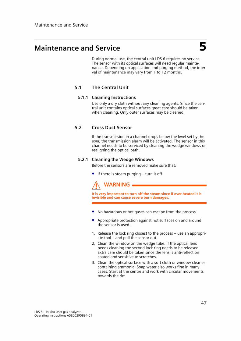
Maintenance and Service
Maintenance and Service 5During normal use, the central unit LDS 6 requires no service. The sensor with its optical surfaces will need regular mainte-nance. Depending on application and purging method, the inter-val of maintenance may vary from 1 to 12 months.
5.1 The Central Unit
5.1.1 Cleaning InstructionsUse only a dry cloth without any cleaning agents. Since the cen-tral unit contains optical surfaces great care should be taken when cleaning. Only outer surfaces may be cleaned.
5.2 Cross Duct Sensor
If the transmission in a channel drops below the level set by the user, the transmission alarm will be activated. The sensor in this channel needs to be serviced by cleaning the wedge windows or realigning the optical path.
5.2.1 Cleaning the Wedge WindowsBefore the sensors are removed make sure that:
• If there is steam purging – turn it off!
WARNING
It is very important to turn off the steam since if over-heated it is invisible and can cause severe burn damages.
• No hazardous or hot gases can escape from the process.
• Appropriate protection against hot surfaces on and around the sensor is used.
1. Release the lock ring closest to the process – use an appropri-ate tool – and pull the sensor out.
2. Clean the window on the wedge tube. If the optical lens needs cleaning the second lock ring needs to be released. Extra care should be taken since the lens is anti-reflection coated and sensitive to scratches.
3. Clean the optical surface with a soft cloth or window cleaner containing ammonia. Soap water also works fine in many cases. Start at the centre and work with circular movements towards the rim.
LDS 6 – In-situ laser gas analyzerOperating instructions A5E00295894-01
47

Maintenance and Service
4. Remove all dust particles using pressurized air or flushing water.
5. When the sensor is re-installed make sure that the guide pin fits the hole on the purging flange. Screw on the lock ring and tighten it gently with the tool.
If this operation is performed properly, it will not affect the align-ment of the sensor.
5.2.2 Alignment of the SensorsMount the sensors, receiver and transmitter, with gaskets on the flanges and cross tighten the bolts. Align the sensors in the fol-lowing steps:
Roughly align the adjustable flange so that the two discs are par-allel.
Receiver side
Figure 5.1 Remove the receiver sensor box
Release the receiver lock ring furthest from the process – use the supplied tool – and remove the receiver sensor.
LDS 6 – In-situ laser gas analyzerOperating instructions A5E00295894-01
48
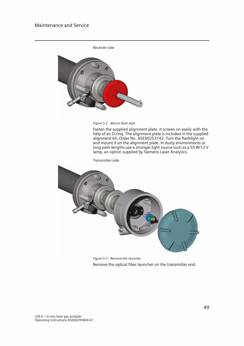
Maintenance and Service
Receiver side
Figure 5.2 Mount flash light
Fasten the supplied alignment plate. It screws on easily with the help of an O-ring. The alignment plate is included in the supplied alignment kit, Order No. A5E00253142. Turn the flashlight on and mount it on the alignment plate. In dusty environments or long path-lengths use a stronger light source such as a 55 W/12 V lamp, an option supplied by Siemens Laser Analytics.
Transmitter side
Figure 5.3 Remove the launcher
Remove the optical fiber launcher on the transmitter end.
LDS 6 – In-situ laser gas analyzerOperating instructions A5E00295894-01
49

Maintenance and Service
Transmitter side
Figure 5.4 Align the transmitter
Mount the cross-hair and align the transmitter with the two hex-agonal socket screws, by tightening and loosening them until the light dot is centered in the inner ring of the cross-hair.
LDS 6 – In-situ laser gas analyzerOperating instructions A5E00295894-01
50

Maintenance and Service
Transmitter side
Figure 5.5 Center the light dot
The light dot should have a perfect round shape. If the light dot is oval or scattered it might be necessary to adjust the welded flanges or remove any objects that might be blocking the light-path.
Transmitter side
Figure 5.6 Mount the flash light in the transmitter
Move the flashlight to the transmitter and replace the cross-hair with it.
LDS 6 – In-situ laser gas analyzerOperating instructions A5E00295894-01
51

Maintenance and Service
Receiver side
Figure 5.7 Align the receiver
Remove the alignment plate and remount the receiver sensor. Tighten the quick coupling firmly. Remove the detector card and replace it with the cross-hair.
Align the receiver with the two hexagonal socket screws, by tightening and loosening them until the light-dot is centered on the cross-hair.
NOTEThe stability of the sensor alignment depends on the stability of the construction to which the customer’s flange is mounted. If the incin-erator wall or smoke duct is subject to movements due to, for instance, thermal changes CD 6 will need repeated realignment.
LDS 6 – In-situ laser gas analyzerOperating instructions A5E00295894-01
52
Maintenance and Service
This can be avoided by mounting the sensor pair on an external, more stable base, like a concrete or steel support.
5.3 Calibration Check
The calibration can be checked at any time by using the optional teflon coated verification cell FC3002 or FC3002H which is a heated version. Normally the LDS 6 does not have to be re-cali-brated but due to local regulations the calibration may have to be checked with regular intervals.
CAUTION
The calibration procedure is critical and should only be performed either by Siemens Laser Analytics AB or by certified personnel at site.
5.4 Reconfiguration of Temperature Compensation
5.4.1 Manual to external1. Starting from “Measuring Window”, navigate to the compo-
nent or channel for which you want to change the compensa-tion mode. Press the soft key for “Configuration”. Enter the password for privilege level 2 (the password is factory-set to the value “222”, but may have been replaced by a new one). Press “Continue” twice and then choose “83 Temperature Cor-rection”.
2. Press the first soft key to change the text “manual temp. value” to “external temp. signal on input 1”.
3. Set the measuring range to the temperatures that correspond to the analog input signal 4 mA and 20 mA respectively.
4. Set the limits to suitable values. If the temperature signal exceeds the limits a fault will be triggered. Note that the lim-its cannot be set outside a certain range.
5. Make sure that the symbol next to the text “Temperature corr. active” is marked (it should be a filled square).
6. Press MEAS to return to measurement screen. Press MEAS again to loose privileges.
7. Hardware connections: Connect the 4-20 mA wires to pin 3 and 11 on the 15 pin trapezoidal plug (D-SUB plug) at the rear. The conductor cross-section should be >0.5 mm2. It is recommended to use cables of type JE-LiYCY... BD.
8. The procedure has to be repeated for other channels. It is not necessary to repeat it for more than one component per channel since it is a channel specific function.
LDS 6 – In-situ laser gas analyzerOperating instructions A5E00295894-01
53
Maintenance and Service
5.4.2 External to manual1. Starting from “Measuring Window”, navigate to the compo-
nent or channel for which you want to change the compensa-tion mode. Press the soft key for “Configuration”. Enter the password for privilege level 2 (the password is factory-set to the value “222”, but may have been replaced by a new one). Press “Continue” twice and then choose “83 Temperature Cor-rection”.
2. Press the first soft key to change the text “external temp. sig-nal on input 1” to “manual temp. value”.
3. Set the manual value to the preferred value.4. Make sure that the symbol next to the text “Temperature corr.
active” is marked (it should be a filled square).5. Press MEAS to return to measurement screen. Press MEAS
again to loose privileges.6. The procedure has to be repeated for other channels. It is not
necessary to repeat it for more than one component per channel since it is a channel specific function.
5.5 Reconfiguration of Pressure Compensation
5.5.1 Manual to external1. Starting from “Measuring Window”, navigate to the compo-
nent or channel for which you want to change the compensa-tion mode. Press the soft key for “Configuration”. Enter the password for privilege level 2 (the password is factory-set to the value “222”, but may have been replaced by a new one). Press “Continue” twice and then choose “82 Pressure Correc-tion”.
2. Press the first soft key to change the text “manual pressure value” to “external pressure signal on input 2”.
3. Set the measuring range to the pressures that correspond to the analog input signal 4 mA and 20 mA respectively.
4. Set the limits to suitable values. If the temperature signal exceeds the limits a fault will be triggered. Note that the lim-its cannot be set outside a certain range.
5. Make sure that the symbol next to the text “Pressure corr. active” is marked (it should be a filled square).
6. Press MEAS to return to measurement screen. Press MEAS again to loose privileges.
7. Hardware connections: Connect the 4-20 mA wires to pin 4 and 12 on the 15 pin trapezoidal plug (D-SUB plug) at the rear. The conductor cross-section should be >0.5 mm2. It is recommended to use cables of type JE-LiYCY... BD.
8. The procedure has to be repeated for other channels. It is not necessary to repeat it for more than one component per channel since it is a channel specific function.
LDS 6 – In-situ laser gas analyzerOperating instructions A5E00295894-01
54

Maintenance and Service
5.5.2 External to manual1. Starting from “Measuring Window”, navigate to the compo-
nent or channel for which you want to change the compensa-tion mode. Press the soft key for “Configuration”. Enter the password for privilege level 2 (the password is factory-set to the value “222”, but may have been replaced by a new one). Press “Continue” twice and then choose “82 Pressure Correc-tion”.
2. Press the first soft key to change the text “external pressure signal on input 1” to “manual temp. value”.
3. Set the manual value to the preferred value.4. Make sure that the symbol next to the text “Pressure corr.
active” is marked (it should be a filled square).5. Press MEAS to return to measurement screen. Press MEAS
again to loose privileges.6. The procedure has to be repeated for other channels. It is not
necessary to repeat it for more than one component per channel since it is a channel specific function.
5.6 Reconfiguration of the Path Length
1. Starting from “Measuring window”, press the soft key next to the component for which you want to change the path length. Press the soft key for “Configuration”. Enter the pass-word for privilege level 2 (the password is factory-set to the value “222”, but may have been replaced by a new one). Press “Continue” twice and then choose “84 Path Length”.
2. Press first soft key to edit the path length. Enter the new path length and press ENTER.
3. Press MEAS to return to measurement screen. Press MEAS again to loose privileges.
4. The procedure has to be repeated for other channels. It is not necessary to repeat the procedure for more than one compo-nent per channel since this function is a channel-specific function.
LDS 6 – In-situ laser gas analyzerOperating instructions A5E00295894-01
55

Maintenance and Service
LDS 6 – In-situ laser gas analyzerOperating instructions A5E00295894-01
56
Technical Description
Technical Description 66.1 Introduction
The LDS 6 is a system for on-line in situ gas analysis providing continuous presentation of accurate and real-time measure-ments.
The gas concentration is measured using line absorption spec-troscopy. Cross sensitivities to other gases are eliminated in the measurements due to the frequency purity of the laser enabling selective detection of individual absorption lines.
The LDS 6 consists of a sensor pair (measuring heads) and a cen-tral unit interconnected using optical fiber cables. The central unit and the sensor can be installed several kilometers apart.
The light source is a diode laser with a wavelength that can be tuned within a narrow spectral range. An optical fiber guides the light from the central unit to the sensor, where it is directed into the measuring section. The laser beam passes through the gas in the measuring section and is partially absorbed there. The light attenuated in this way is detected by the receiver and is returned to the central unit. The variation in the intensity of the laser light in the vicinity of the absorption line is measured, and the con-centration of the gas being measured is calculated using the sec-ond harmonic of the detected signal.
The LDS 6 can measure at three locations simultaneously. Each measurement point needs a receiver board in the central unit as well as a sensor with cabling.
The LDS 6 operates as an independent unit. A 100-240 VAC main power supply is all that is required. The gas concentration and instrument status are indicated on the graphical display. The gas concentration is also continuously given as an analog 4-20 mA output. Several different alarms can also be obtained externally. The unit also accepts different inputs, analog and binary, such as process temperature and pressure.
LDS 6 can also be operated remotely via the Ethernet port with a PC running Windows 95/98/ME or Windows NT/2000/XP. It is also possible to connect to LDS 6 via modem over the public tele-phone net. The external connection requires the optional soft-ware LDSComm (LDS Communication Client) to be installed on the remote computer. All aspects of LDS 6 can be controlled in this way.
LDS 6 – In-situ laser gas analyzerOperating instructions A5E00295894-01
57
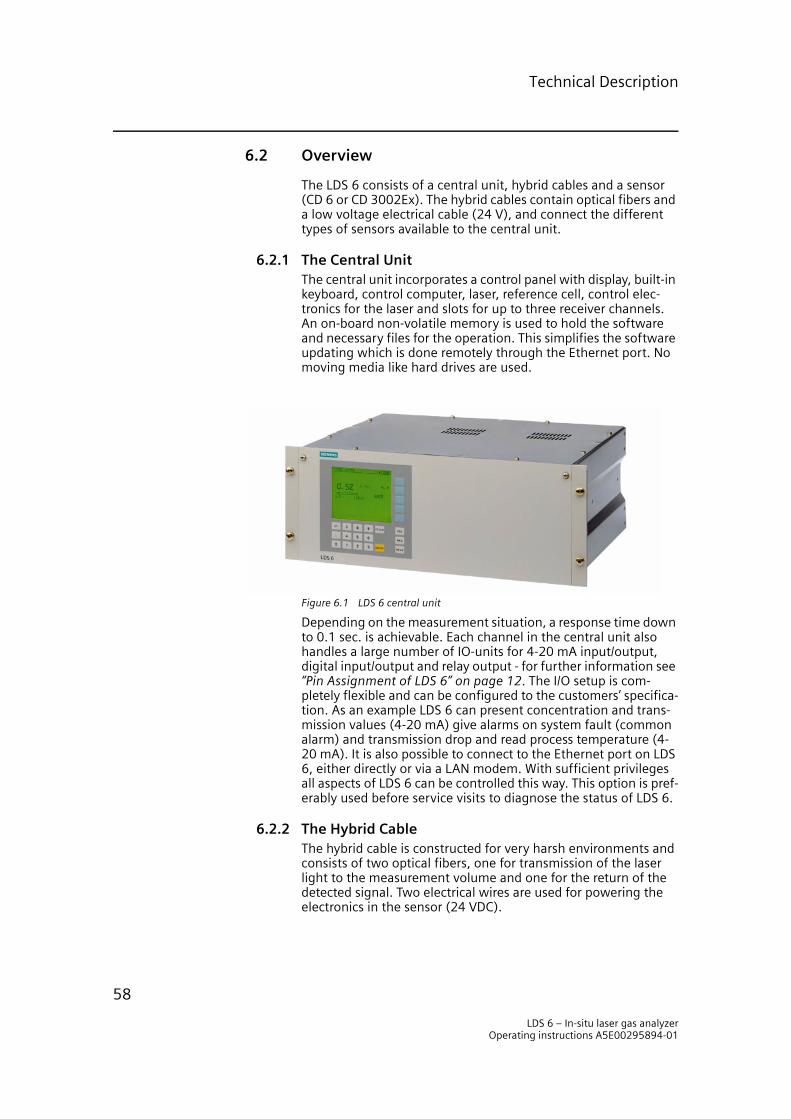
Technical Description
6.2 Overview
The LDS 6 consists of a central unit, hybrid cables and a sensor (CD 6 or CD 3002Ex). The hybrid cables contain optical fibers and a low voltage electrical cable (24 V), and connect the different types of sensors available to the central unit.
6.2.1 The Central UnitThe central unit incorporates a control panel with display, built-in keyboard, control computer, laser, reference cell, control elec-tronics for the laser and slots for up to three receiver channels. An on-board non-volatile memory is used to hold the software and necessary files for the operation. This simplifies the software updating which is done remotely through the Ethernet port. No moving media like hard drives are used.
Figure 6.1 LDS 6 central unit
Depending on the measurement situation, a response time down to 0.1 sec. is achievable. Each channel in the central unit also handles a large number of IO-units for 4-20 mA input/output, digital input/output and relay output - for further information see “Pin Assignment of LDS 6” on page 12. The I/O setup is com-pletely flexible and can be configured to the customers’ specifica-tion. As an example LDS 6 can present concentration and trans-mission values (4-20 mA) give alarms on system fault (common alarm) and transmission drop and read process temperature (4-20 mA). It is also possible to connect to the Ethernet port on LDS 6, either directly or via a LAN modem. With sufficient privileges all aspects of LDS 6 can be controlled this way. This option is pref-erably used before service visits to diagnose the status of LDS 6.
6.2.2 The Hybrid CableThe hybrid cable is constructed for very harsh environments and consists of two optical fibers, one for transmission of the laser light to the measurement volume and one for the return of the detected signal. Two electrical wires are used for powering the electronics in the sensor (24 VDC).
LDS 6 – In-situ laser gas analyzerOperating instructions A5E00295894-01
58
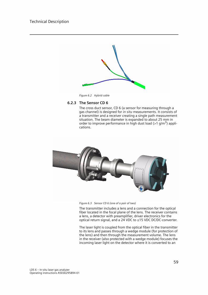
Technical Description
Figure 6.2 Hybrid cable
6.2.3 The Sensor CD 6The cross duct sensor, CD 6 (a sensor for measuring through a gas channel) is designed for in situ measurements. It consists of a transmitter and a receiver creating a single path measurement situation. The beam diameter is expanded to about 25 mm in order to improve performance in high dust load (>1 g/m3) appli-cations.
Figure 6.3 Sensor CD 6 (one of a pair of two)
The transmitter includes a lens and a connection for the optical fiber located in the focal plane of the lens. The receiver contains a lens, a detector with preamplifier, driver electronics for the optical return signal, and a 24 VDC to ±15 VDC DC/DC-converter.
The laser light is coupled from the optical fiber in the transmitter to its lens and passes through a wedge module (for protection of the lens) and then through the measurement volume. The lens in the receiver (also protected with a wedge module) focuses the incoming laser light on the detector where it is converted to an
LDS 6 – In-situ laser gas analyzerOperating instructions A5E00295894-01
59

Technical Description
electrical signal. This signal is amplified and converted to an opti-cal signal and returned to the central unit. The mounting of the sensor requires a flange with the dimensions DN65/PN6 or ANSI 4”/150 lbf.
6.2.4 The Ex Sensor CD 3002ExThe sensor is also available in an Ex-version. This has very low power electronics - intrinsically safe - and an IP65 enclosure.
Figure 6.4 Ex sensor CD 3002Ex (one of a pair of two)
For further information regarding the Ex option please refer to “Explosion Protection - Ex II 1G D T135°C EEx ia IIC T4” on page 5
6.2.5 Protecting the Optical SurfaceThe wedge windows are in many applications exposed to very nasty environments and will get stained very quickly if no mea-sures are taken. A number of existing methods available to keep the wedge windows in good shape are described in the following sections.
Instrument Air PurgingThis is the standard solution to keep the wedge windows free from contamination. It requires a flange equipped with an inlet for purging gas to create an air flow in front of the wedge win-dows and into the process.
NOTEInstrument air is rather expensive and therefore measures should be taken to minimize the consumption. Therefore a pressure regula-tor should be used at the instrument air connection point to facili-tate adjustment of the flow if no flow regulation is applied. If very high air flows (>100 l/min.) are needed an air blower should be used. As an option a needle valve can be supplied and be used instead to give an adjustable air flow of approx. 0- 110 l/min. (with 6000 hPa instrument air).
LDS 6 – In-situ laser gas analyzerOperating instructions A5E00295894-01
60

Technical Description
Gas Flow CalculationsGas flow calculations are slightly complex because gases are compressible fluids whose density changes with pressure. In addition, when the outlet pressure is less than one half of the inlet pressure, the gas reaches sonic velocity in the valve. This is known as “choked flow”, because a further decrease in outlet pressure does not increase the flow. In this application we are dealing with choked flow. The following empirical equation can be used to calculate the flow under these circumstances - assum-ing that the process pressure (Pp) is 1023 hPa:
q = 3.197 · Cv · P1 · sqrt[1/((T1+273) · Gg)]
where
q = the flow rate on the low pressure side [Nltr/min.] Cv = the flow coefficient (0,1 for the needle valve in our standard sensor) P1 = the inlet absolute pressure [hPa] Gg = the gas specific gravity (air = 1.0) T1 = the upstream temperature [°C].
The flow (q) of instrument air at p1 = 6000 hPa and T1 = 25 °C through the needle valve when it is fully opened would then be a little more than 110 Nltr/min.
For a more complete detail see the picture below. It shows the flow (q) as a function of the up-stream pressure (P1). There are two parameters in the diagram, i.e. the process pressure (Pp) and the temperature of the purge gas which is assumed to be air (Gg = 1.0). The diagram shows the flow through a system with a total Cv of 0.1. The flow increases linearly with Cv.
Figure 6.5 Purge air flow rate
Pp = 3039 hPa
Pp = 2026 hPa
Pp = 1013 hPa
T1 = 25 °C
T1 = 100 °C
0 1 2 3 4 5 6 70
20
40
60
80
100
120
140
P1 [x1013 hPa]
q (C
v =
0.1
) [N
ltr/
min
]
LDS 6 – In-situ laser gas analyzerOperating instructions A5E00295894-01
61

Technical Description
Purging with Air BlowerIn applications with high dust load purging with air blower must be considered. The air speed when standard purging is used is too low to prevent build-up of dust in the flange tubes. Our stan-dard air blower solution will provide up to about 1000 l/min.
Steam PurgingIf overheated steam is available it is a candidate for purging of the wedge windows. It has some advantages like high tempera-ture (to prevent salt condensation) and low maintenance. An additional advantage when oxygen is measured is that steam is free of oxygen and will not interfere with the measurements; consequently when water is measured this becomes a disadvan-tage. When oxygen is measured N2 purging of the sensor hous-ing might also be necessary to obtain maximum performance.
The requirements on the steam are that it must be ~200 °C and overheated at the sensor location. See the steam installation instruction provided by Siemens Laser Analytics AB. As an option a steam conditioning unit can be offered. We recommend its use for this kind of applications.
6.3 Measurement Principle
The LDS 6 measures the gas concentration by using line absorp-tion spectroscopy. If the absorption of a gas mixture is plotted versus the wavelength, it can be seen that absorption only takes place at certain wavelengths in the spectral region. These extremely narrow absorption peaks are referred to as absorption lines as shown in the figure below.
Figure 6.6 Absorption lines1.543 1.5435 1.544 1.5445 1.545 1.5455 1.546
0.1
0.0
0.2
0.3
0.4
0.5
0.6
0.7
0.8 H2O 15%
NH3 5ppm
1.0
0.9
LDS 6 – In-situ laser gas analyzerOperating instructions A5E00295894-01
62

Technical Description
The measured gas (here ammonia) is identified by comparing with the spectrum from a built in reference cell. To perform line absorption spectroscopy, the LDS 6 uses a diode laser as light source since its spectral width is much narrower than the width of the absorption line. Furthermore, the wavelength of the laser can be selected to be near one absorption line of the gas to be measured. By varying the current and temperature the laser wavelength is tuned to cover the required narrow spectral range which includes the absorption line. When tuning the laser light over the absorption line it is partially absorbed. From the received laser signal the area beneath the absorption line can be extracted, which is a measure of the gas concentration.
The light emitted from the laser is split into five beams. The first beam passes through a reference gas and is then detected. This reference signal is used for continuous self-calibration and zero point determination of the system, taking temperature and pres-sure into account. The second beam is used for measuring the intensity of the laser and provides the control unit with informa-tion relating to the state of the laser. The third, fourth and/or fifth beams (depending on how many channels are in use) are con-ducted via the optical fiber with the E2000 connectors to the sensor heads, where it enters the measuring sections. When the laser light passes through the gas in the measuring section it is partially absorbed. The light is detected by the receiver and after signal conditioning it is converted to an optical signal and returned to the central unit using the multi mode optical fiber (with the SMA connectors).
LDS 6 – In-situ laser gas analyzerOperating instructions A5E00295894-01
63

Technical Description
Figure 6.7 Block diagram of LDS 6
The concentration of the measured gas is calculated from the absorption spectrum for the measurement channel (PT). Any change in the measurement conditions, for example as a result of a higher dust load in the flue gas or contamination of the opti-cal components, is compensated for automatically to guarantee the accuracy of the measurement results under a wide range of operating conditions.
6.4 Mode of Operation
The operation of LDS 6 is based on the fact that light propagating through a gas mixture will be absorbed - obeying the Beer-Lam-bert law - at certain narrow wavelength bands. This is where the gases possess molecular transitions forming narrow absorption lines.
The light source in LDS 6 is a semi-conductor laser tuned to an appropriate absorption line for the gas to be measured. The laser light is spectrally much narrower than the gas absorption line
PT
Laser light
Return LED light
Electrical signals
Central unit
Hybrid
cable
Measurement
path
Measurement
path
CPU andpresentation
PR
P0
Reference cell
Diode laser
Opticalcoupler
Signal processing
Sm
oke
sta
ck
Lasercontrol
LDS 6 – In-situ laser gas analyzerOperating instructions A5E00295894-01
64

Technical Description
and this, together with a proper choice of absorption line, will result in low interference from other gases.
The light is modulated in the audio domain, both in frequency and in amplitude, to facilitate detection on the second harmonic as well as elimination of contribution from spectrally broad absorption originating from dust, smoke, etc.
6.4.1 Single Line SpectroscopyThe absorption of a homogenous material is given by Beer-Lam-bert law. It states that α(ν), the fraction of photons absorbed over a path dz, is constant. This constant is called the absorption coefficient.
δI(ν)/I(ν) = dz α(ν)
Integrating over the path L gives:
I(ν) = I0exp(α(ν)L)
The absorption comes from two different kind of sources:
1)σ – dust and other components spectrally broad enough to act as a constant absorption over the wavelength scan.
2) αi(ν) – gas components in the path having a molecular transi-tion in the scanned wavelength region.
α(ν) = σ + Σαi(ν)
The absorption coefficient α(ν) for gaseous species varies sharply with the optical frequency. For one gas component
αi(ν) = Si g(ν - ν0) Ni
where Si is the molecular line intensity, Ni is the number of absorbing molecules per cm3 of atmosphere and g(ν - ν0) is the normalized line shape. The Bolzman population factor is con-tained within Si.
The number of absorbing molecules from the gas i at the partial pressure pi is given by the ideal gas law
Ni = NL (T0/T)(pi/p)
where T and p is the actual gas temperature and pressure respec-tively, T0 is the reference temperature at STP (273.16K) and NL is the number of molecules in one mole at STP. The gas absorption will have a temperature and pressure dependence from the molecular line parameters and from the fact that the number of molecules in the measuring volume change according to the ideal gas law. If we set Ki(T, p) = Si NL (T0/T) and define the opti-cal line strength per unit atmosphere of gas which now include all temperature and pressure effects we obtain
LDS 6 – In-situ laser gas analyzerOperating instructions A5E00295894-01
65
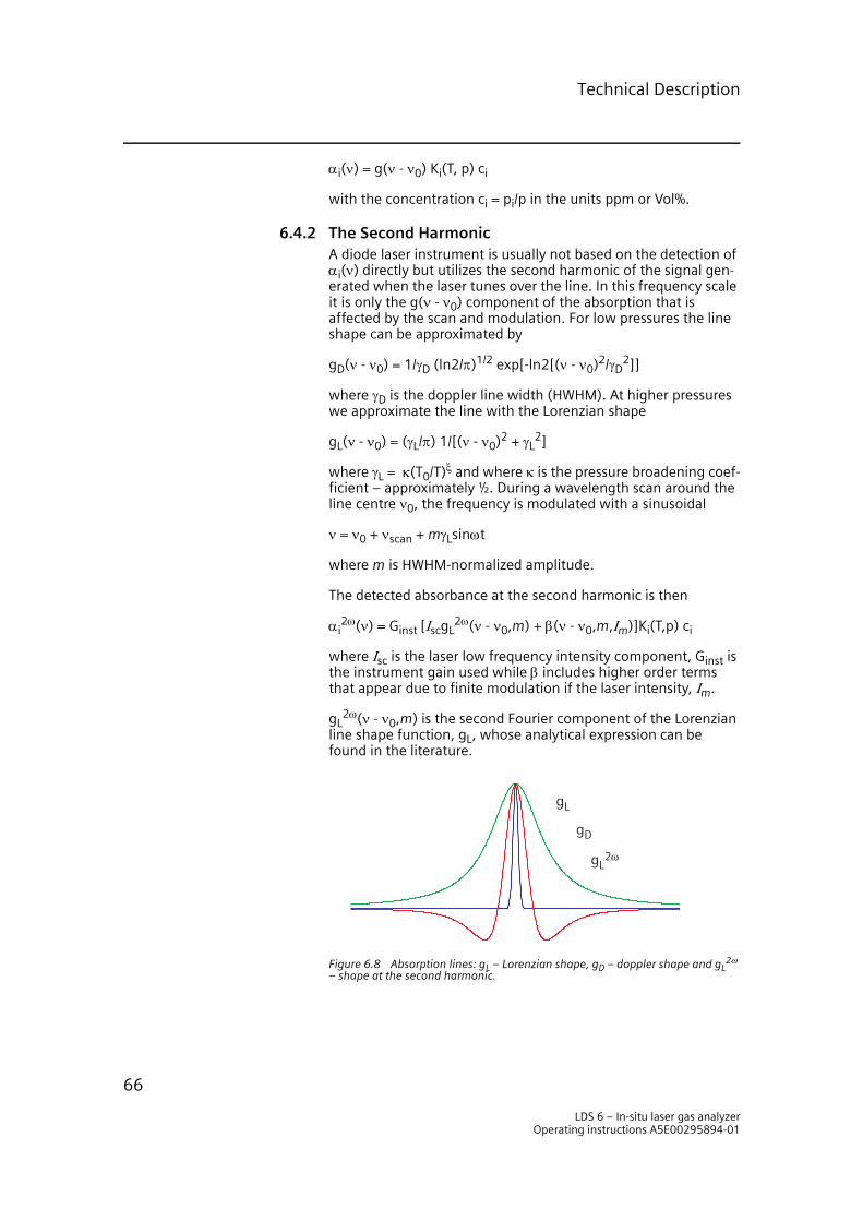
Technical Description
αi(ν) = g(ν - ν0) Ki(T, p) ci
with the concentration ci = pi/p in the units ppm or Vol%.
6.4.2 The Second HarmonicA diode laser instrument is usually not based on the detection of αi(ν) directly but utilizes the second harmonic of the signal gen-erated when the laser tunes over the line. In this frequency scale it is only the g(ν - ν0) component of the absorption that is affected by the scan and modulation. For low pressures the line shape can be approximated by
gD(ν - ν0) = 1/γD (ln2/π)1/2 exp[-ln2[(ν - ν0)2/γD2]]
where γD is the doppler line width (HWHM). At higher pressures we approximate the line with the Lorenzian shape
gL(ν - ν0) = (γL/π) 1/[(ν - ν0)2 + γL2]
where γL = κ(T0/T)ξ and where κ is the pressure broadening coef-ficient – approximately ½. During a wavelength scan around the line centre ν0, the frequency is modulated with a sinusoidal
ν = ν0 + νscan + mγLsinωt
where m is HWHM-normalized amplitude.
The detected absorbance at the second harmonic is then
αi2ω(ν) = Ginst [ΙscgL
2ω(ν - ν0,m) + β(ν - ν0,m,Ιm)]Ki(T,p) ci
where Ιsc is the laser low frequency intensity component, Ginst is the instrument gain used while β includes higher order terms that appear due to finite modulation if the laser intensity, Ιm.
gL2ω(ν - ν0,m) is the second Fourier component of the Lorenzian
line shape function, gL, whose analytical expression can be found in the literature.
Figure 6.8 Absorption lines: gL – Lorenzian shape, gD – doppler shape and gL2ω
– shape at the second harmonic.
gL2ω
gL
gD
LDS 6 – In-situ laser gas analyzerOperating instructions A5E00295894-01
66
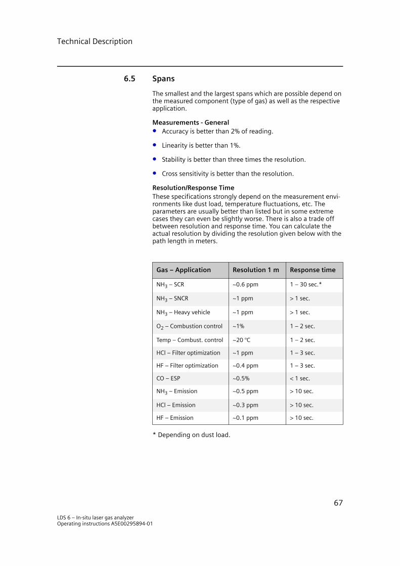
Technical Description
6.5 Spans
The smallest and the largest spans which are possible depend on the measured component (type of gas) as well as the respective application.
Measurements - General• Accuracy is better than 2% of reading.
• Linearity is better than 1%.
• Stability is better than three times the resolution.
• Cross sensitivity is better than the resolution.
Resolution/Response TimeThese specifications strongly depend on the measurement envi-ronments like dust load, temperature fluctuations, etc. The parameters are usually better than listed but in some extreme cases they can even be slightly worse. There is also a trade off between resolution and response time. You can calculate the actual resolution by dividing the resolution given below with the path length in meters.
* Depending on dust load.
Gas – Application Resolution 1 m Response time
NH3 – SCR ~0.6 ppm 1 – 30 sec.*
NH3 – SNCR ~1 ppm > 1 sec.
NH3 – Heavy vehicle ~1 ppm > 1 sec.
O2 – Combustion control ~1% 1 – 2 sec.
Temp – Combust. control ~20 °C 1 – 2 sec.
HCl – Filter optimization ~1 ppm 1 – 3 sec.
HF – Filter optimization ~0.4 ppm 1 – 3 sec.
CO – ESP ~0.5% < 1 sec.
NH3 – Emission ~0.5 ppm > 10 sec.
HCl – Emission ~0.3 ppm > 10 sec.
HF – Emission ~0.1 ppm > 10 sec.
LDS 6 – In-situ laser gas analyzerOperating instructions A5E00295894-01
67
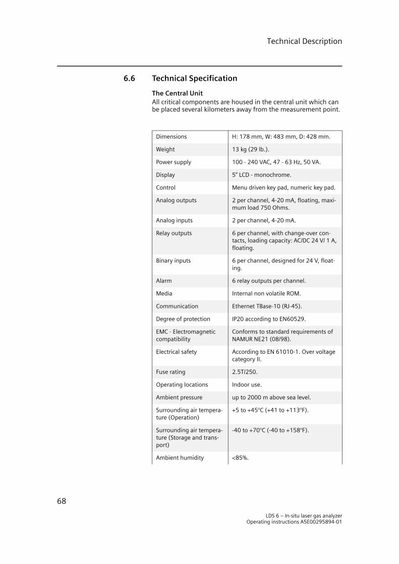
Technical Description
6.6 Technical Specification
The Central UnitAll critical components are housed in the central unit which can be placed several kilometers away from the measurement point.
Dimensions H: 178 mm, W: 483 mm, D: 428 mm.
Weight 13 kg (29 lb.).
Power supply 100 - 240 VAC, 47 - 63 Hz, 50 VA.
Display 5” LCD - monochrome.
Control Menu driven key pad, numeric key pad.
Analog outputs 2 per channel, 4-20 mA, floating, maxi-mum load 750 Ohms.
Analog inputs 2 per channel, 4-20 mA.
Relay outputs 6 per channel, with change-over con-tacts, loading capacity: AC/DC 24 V/ 1 A, floating.
Binary inputs 6 per channel, designed for 24 V, float-ing.
Alarm 6 relay outputs per channel.
Media Internal non volatile ROM.
Communication Ethernet TBase-10 (RJ-45).
Degree of protection IP20 according to EN60529.
EMC - Electromagnetic compatibility
Conforms to standard requirements of NAMUR NE21 (08/98).
Electrical safety According to EN 61010-1. Over voltage category II.
Fuse rating 2.5T/250.
Operating locations Indoor use.
Ambient pressure up to 2000 m above sea level.
Surrounding air tempera-ture (Operation)
+5 to +45°C (+41 to +113°F).
Surrounding air tempera-ture (Storage and trans-port)
-40 to +70°C (-40 to +158°F).
Ambient humidity <85%.
LDS 6 – In-situ laser gas analyzerOperating instructions A5E00295894-01
68
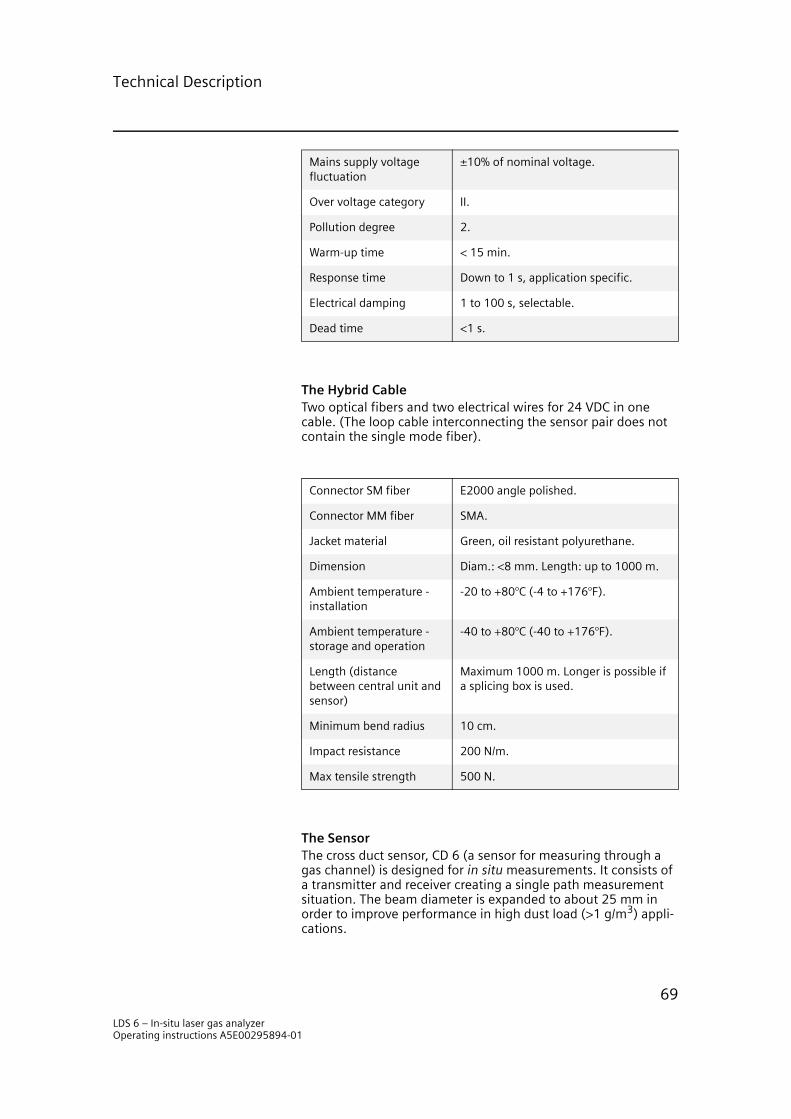
Technical Description
The Hybrid CableTwo optical fibers and two electrical wires for 24 VDC in one cable. (The loop cable interconnecting the sensor pair does not contain the single mode fiber).
The SensorThe cross duct sensor, CD 6 (a sensor for measuring through a gas channel) is designed for in situ measurements. It consists of a transmitter and receiver creating a single path measurement situation. The beam diameter is expanded to about 25 mm in order to improve performance in high dust load (>1 g/m3) appli-cations.
Mains supply voltage fluctuation
±10% of nominal voltage.
Over voltage category II.
Pollution degree 2.
Warm-up time < 15 min.
Response time Down to 1 s, application specific.
Electrical damping 1 to 100 s, selectable.
Dead time <1 s.
Connector SM fiber E2000 angle polished.
Connector MM fiber SMA.
Jacket material Green, oil resistant polyurethane.
Dimension Diam.: <8 mm. Length: up to 1000 m.
Ambient temperature - installation
-20 to +80°C (-4 to +176°F).
Ambient temperature - storage and operation
-40 to +80°C (-40 to +176°F).
Length (distance between central unit and sensor)
Maximum 1000 m. Longer is possible if a splicing box is used.
Minimum bend radius 10 cm.
Impact resistance 200 N/m.
Max tensile strength 500 N.
LDS 6 – In-situ laser gas analyzerOperating instructions A5E00295894-01
69

Technical Description
The transmitter includes a lens and a connection for the optical fiber located in the focal plane of the lens. The receiver contains a lens, a detector with preamplifier, driver electronics for the optical return signal, and a 24 VDC to ±15 VDC DC/DC-converter.
The laser light is coupled from the optical fiber in the transmitter to the transmitter lens and passes through the measurement vol-ume. The lens in the receiver focuses the incoming laser light on the detector where it is converted to an electrical signal. This sig-nal is amplified and converted to an optical signal and returned to the central unit LDS 6.
Dimension, sensor box Ø: 163 mm, D: 105 mm.CD 3002Ex:H: 195 mm, W: 195 mm, D: 105 mm.
Dimension, purging tube L: 400, 800 or 1200 mm, OD: 44 mm, ID: 40 mm. Custom lengths up to 1300 mm is also available.
Weight 2 x 11 kg (24 lb).
Power supply Integrated in the central unit. External supply may be used: 18 V - 36 V DC.CD 3002Ex:According to the intrinsically-safe stan-dards (EN 50020 or DIN EN 50020, and IEC 60079-11 or EN 60079-11).
Power consumption Approx. 2 W.CD 3002Ex:Max. 0.58 W.
Degree of protection IP67 according to EN60529.CD 3002Ex:IP65 according to EN60529.
EMC - Electromagnetic compatibility
Conforms to standard requirements of NAMUR NE21 (08/98).
Electrical safety According to EN 61010-1, over voltage test category II.
Fuse rating Central unit power supply, 1 A, poly switch.
Permissible ambient tem-perature (Operation)
-30 to +70°C (-22 to +158°F).CD 3002Ex:-30 to +60°C (-22 to +140°F).
Permissible ambient tem-perature (Storage and transport)
-40 to +70°C (-40 to +158°F).
LDS 6 – In-situ laser gas analyzerOperating instructions A5E00295894-01
70
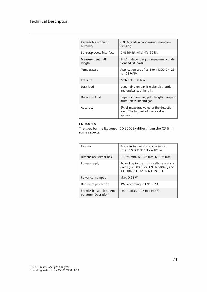
Technical Description
CD 3002ExThe spec for the Ex sensor CD 3002Ex differs from the CD 6 in some aspects.
Permissible ambient humidity
< 95% relative condensing, non-con-densing.
Sensor/process interface DN65/PN6 / ANSI 4”/150 lb.
Measurement path length
1-12 m depending on measuring condi-tions (dust load).
Temperature Application specific: -5 to +1300°C (+23 to +2370°F).
Pressure Ambient ± 50 hPa.
Dust load Depending on particle size distribution and optical path length.
Detection limit Depending on gas, path length, temper-ature, pressure and gas.
Accuracy 2% of measured value or the detection limit. The highest of these values applies.
Ex class Ex-protected version according to Ex II 1G D T135° EEx ia IIC T4.
Dimension, sensor box H: 195 mm, W: 195 mm, D: 105 mm.
Power supply According to the intrinsically-safe stan-dards (EN 50020 or DIN EN 50020, and IEC 60079-11 or EN 60079-11).
Power consumption Max. 0.58 W.
Degree of protection IP65 according to EN60529.
Permissible ambient tem-perature (Operation)
-30 to +60°C (-22 to +140°F).
LDS 6 – In-situ laser gas analyzerOperating instructions A5E00295894-01
71

Technical Description
LDS 6 – In-situ laser gas analyzerOperating instructions A5E00295894-01
72

Spare Parts List
Spare Parts List 77.1 Spare Parts
This spare parts list corresponds to the technical state of August 2004. The rating plate shows the year of construction (coded) of the gas analyzer LDS 6. It also shows the MLFB number and the instrument serial number.
Figure 7.1 Rating plate of the LDS 6.
7.1.1 Ordering InstructionsAll orders should specify the following:
1. Quantity.2. Designation.3. Order number.4. MLFB number and serial number of the instrument to which
the spare part will be used.
7.1.2 Spare Parts ListAll spare parts are identified by an order number. In addition to this the cables must have a MLFB number identifying type and length - see the figure “Spare cables” on page 74.
Example 1: The order number A5E00253263 corresponds to an opto module for ammonia.
Example 2: The order number A5E00253111 paired with the MLFB number 7MB8001-0CH00 corresponds to a 50 m long hybrid cable for all gases except oxygen.
To achieve a correct order (MLFB) number for the cables, start with the cable prefix 7MB8001 and add each digit in the right position according to the spare cables list below.
LDS 6
100-240 VAC 50/60 Hz, 50 VA
7MB6021-0CF00-0FX1
Made in Sweden
Serial No. 6892
min 2%02
SIEMENSMLFB-Nr.MLFB No.MLFB.No
Fabr.-Nr.Serial No.No de fabrication
LDS 6 – In-situ laser gas analyzerOperating instructions A5E00295894-01
73
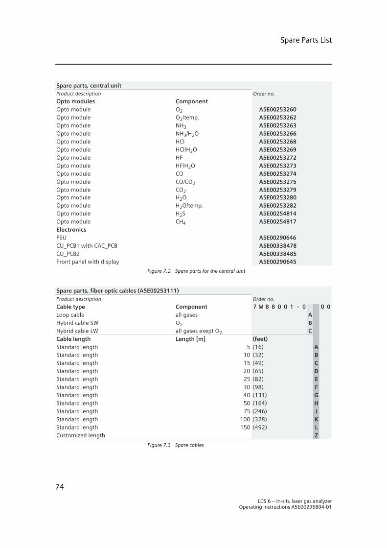
Spare Parts List
Figure 7.2 Spare parts for the central unit
Figure 7.3 Spare cables
Spare parts, central unit
Opto modules ComponentOpto module O2 A5E00253260Opto module O2/temp. A5E00253262Opto module NH3 A5E00253263Opto module NH3/H2O A5E00253266Opto module HCl A5E00253268Opto module HCl/H2O A5E00253269Opto module HF A5E00253272Opto module HF/H2O A5E00253273Opto module CO A5E00253274Opto module CO/CO2 A5E00253275Opto module CO2 A5E00253279Opto module H2O A5E00253280Opto module H2O/temp. A5E00253282Opto module H2S A5E00254814Opto module CH4 A5E00254817ElectronicsPSU A5E00290646CU_PCB1 with CAC_PCB A5E00338478CU_PCB2 A5E00338485Front panel with display A5E00290645
Product description Order no.
Spare parts, fiber optic cables (A5E00253111)
Cable type ComponentLoop cable all gases AHybrid cable SW O2 BHybrid cable LW all gases exept O2 CCable length Length [m] (feet)Standard length 5 (16) AStandard length 10 (32) BStandard length 15 (49) CStandard length 20 (65) DStandard length 25 (82) EStandard length 30 (98) FStandard length 40 (131) GStandard length 50 (164) HStandard length 75 (246) JStandard length 100 (328) KStandard length 150 (492) LCustomized length Z
Product description Order no.
7 M B 8 0 0 1 - 0 0 0
LDS 6 – In-situ laser gas analyzerOperating instructions A5E00295894-01
74

Spare Parts List
Figure 7.4 Spare parts for sensors
Spare parts, sensors
Sensors completeOrder via MLFB 7MB6022
Mechanics CD6Window module (quartz) A5E00338487Window module engine, no purging A5E00338490Purging tube, stainless steel, 1 200 mm (*), 1 pcs A5E00338496Purging tube, stainless steel, 400 mm (*), 1 pcs A5E00338504Purging tube, hastelloy, 400 mm (*), 1 pcs A5E00338507Purging tube, Ceramic, 400mm, 1 pcs A5E00338508Purging tube, Plastic, 400mm (*), 1 pcs A5E00338510Sensor box with lens tube (LW, all gases exept O2) A5E00338512Sensor box with lens tube (SW, only valid for O2) A5E00338513
Sensor electronics CD6, completeSW A5E00338533LW InGaAs A5E00338540HighGain LW InGaAs A5E00338541LW Ge (only valid for HCl) A5E00338552
Mechanics for ATEX sensors CD3002Window Module (quartz) A5E00338594Purging tube 400mm Stainless steel A5E00338598
Electronics for ATEX zone 1ATEX SW A5E00338563ATEX LW A5E00338572Barrier electronics kit incl enclosure A5E00338584
(*) delivered with sintered filter/fan adapter
Product description Order no.
Electronics for ATEX zone 2 CD 3002 / CD 6ATEX SWATEX LW
O2 onlyall gases exept O2
Barrier electronics kit incl enclosure
A5E00344344A5E00344345A5E00344346
O2 onlyall gases exept O2
LDS 6 – In-situ laser gas analyzerOperating instructions A5E00295894-01
75

Spare Parts List
Figure 7.5 Sensor accessories
7.2 Return Deliveries
The gas analyzer or spare parts should be returned in the original package material. If the original package material is no longer available, wrap the analyzer in plastic foil and put it in a suffi-ciently large box, lined with padding material (wood shavings or similar). When using wood shavings, the stuffing should be at least 15 cm thick on all sides.
When shipping overseas, the analyzer must be additionally sealed air-tight in polyethylene foil at least 0.2 mm thick with addition of a dry agent (e.g. silica gel). In addition, the transport container should be lined with a layer of union paper.
Please photocopy the enclosed Returned Deliveries Form, fill it in, and send it together with the returned device. In case of war-ranty claim, please enclose your guarantee card.
7.2.1 Addresses for Spare Parts and Returned Deliveries
Spare Parts ServicePlease send your orders for spare parts to the following address: Siemens Laser Analytics, Östergårdsgatan 2-4, 431 53 Mölndal, Tel: +46 31 776 86 00, Fax: +46 31 776 89 47
Spare parts, sensors
AccessoriesFC3002, verification cell, teflon coated A5E00338599FC3002H, heated verification cell, teflon coated A5E00338601
Alignment kit A5E00253142Air blower fan 230 V A5E00253147Air blower fan 115 V A5E00253148Filter for air blower complete A5E00338606Roxtech gaskets A5E00338608Process protection flange A5E00338609LAN Modem incl. Cable A5E00338616D-sub to std. Terminal connection, 15pins (converter) A5E00338618D-sub to std. Terminal connection, 25pins (converter) A5E00338622Cable, D-sub 15pins (1,5m pin to pin) A5E00338626Cable, D-sub 25pins (1,5m pin to pin) A5E00338632
Product description Order no.
A5E00344348A5E00344349A5E00344350A5E00344351
High pressure window flange, borosilicat glass, SS DN80/PN16High pressure window flange, borosilicat glass Hastelloy DN80/PN16High pressure window flange, quartz glass, SS DN80/PN16High pressure window flange, quartz glass, Hastelloy DN80/PN16
LDS 6 – In-situ laser gas analyzerOperating instructions A5E00295894-01
76

Spare Parts List
RepairsTo enable fast detection and elimination of faults, please return the analyzers to the same address as above.
7.2.2 Returned Deliveries Form
Returned Deliveries Form
Repair or Guarantee? (R / G)
Name of Customer
Address
Contact Person
Address for Returned Delivery
Telephone
Fax
Customer
Order Number
Siemens Order Confirmation Number
Device Name
MLBF Number
Serial Number
Description of Fault
Operating Temperature
Operating Pressure
Composition of Process Gas
Duration of Use / Date of First Use
LDS 6 – In-situ laser gas analyzerOperating instructions A5E00295894-01
77

Spare Parts List
LDS 6 – In-situ laser gas analyzerOperating instructions A5E00295894-01
78

INDEX
AAnalog outputs ........................................32Analyzer
analog test .........................................37configuration ................................27, 32diagnostics values ...............................27display measuring ranges ....................28keyboard test ......................................36limits ..................................................30logbook ..............................................27measuring range ................................29parameters .........................................29relay and binary test ...........................37select digits ........................................31setup logbook .....................................32span calibration ..................................29status .................................................26status messages .................................30test ....................................................36transmission .......................................30zero calibration ...................................28
Approved use ........................................1, 3ATEX .........................................................5Attention ...................................................4BBinary inputs ...........................................33Block diagram ..........................................64
CCalibration
span ...................................................29zero ....................................................28
Central unitconnection of hybrid cables ..................9dimensional drawing ..........................17explosion safe option ............................5installation requirements ......................6mounting ...........................................16relative humidity ..................................6technical description ...........................58temperature range ................................6
Coding ....................................................24Connection
electrical ...............................................8DDate/time ................................................31
Dry gas ....................................................39Dust load .................................................13
EEditing of inputs ......................................20Electrical safety .........................................5Entry into main menu
1-or 2-channel system ........................233-channel system ...............................23
Error On/Off ............................................39Explosion protection ..................................5FFlanges
alignment .............................................7dimensions .........................................14preparations .........................................7
Flow calculations .....................................61Function
analyzer-specific .................................25channel-specific ..................................25component-specific ............................25fast selection ......................................24
Function Control ...............................41, 45
GGases and applications ............................67Graphic styling elements .........................21
HHeat safety ................................................5Hybrid cables
connection of .......................................9for oxygen ............................................8installation ...........................................7mounting conditions ............................7optical fibre ........................................14routing .................................................8technical description ...........................58
IInput menu .............................................32In-situ ...................................13, 57, 59, 69Installation Requirements ..........................6
LLaser ...................................................5, 14Laser safety ...............................................5LCD display
contrast setting ..................................31
iLDS 6 – In-situ laser gas analyzerOperating instructions A5E00295894-01
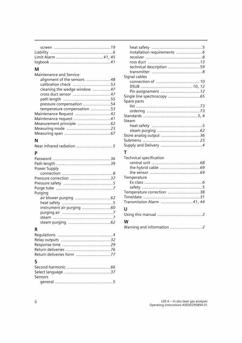
screen ................................................19Liability .....................................................6Limit Alarm ........................................41, 45logbook ...................................................41
MMaintenance and Service
alignment of the sensors .....................48calibration check ................................53cleaning the wedge window ...............47cross duct sensor ................................47path length ........................................55pressure compensation .......................54temperature compensation .................53
Maintenance Request ..............................42Maintenance request ...............................41Measurement principle ............................62Measuring mode .....................................23Measuring span .......................................67
NNear infrared radiation ...............................5PPassword .................................................36Path length ..............................................39Power Supply
connection ...........................................8Pressure correction ..................................37Pressure safety ..........................................5Purge tube ................................................7Purging
air blower purging ..............................62heat safety ...........................................5instrument air purging ........................60purging air ...........................................7steam ...................................................7steam purging ....................................62
RRegulations ...............................................4Relay outputs ..........................................32Response time .........................................29Return deliveries ......................................76Return deliveries form .............................77
SSecond harmonic .....................................66Select language .......................................37Sensors
general .................................................5
heat safety ...........................................5installation requirements ......................6receiver ................................................8ross duct ............................................13technical description ...........................59transmitter ...........................................8
Signal cablesconnection of .....................................10DSUB ............................................10, 12Pin assignement .................................12
Single line spectroscopy ...........................65Spare parts
list ......................................................73ordering .............................................73
Standards ..............................................3, 4Steam
heat safety ...........................................5steam purging ....................................62
Store analog output .................................36Submenu ................................................23Supply and Delivery ...................................4
TTechnical specification
central unit .........................................68the hybrid cable ..................................69the sensor ..........................................69
TemperatureEx class .................................................6safety ...................................................5
Temperature correction ...........................38Time/date ................................................31Transmission Alarm ...........................41, 44
UUsing this manual ......................................2WWarning and information ...........................2
ii LDS 6 – In-situ laser gas analyzerOperating instructions A5E00295894-01

1

simatic pcs 7
A5E00295894D-01 GN: 30340_LDS 6
Operating Instructions Edition 10/2004
Siemens Aktiengesellschaft
Automation and DrivesProcess Instrumentation and Analytics 76181 KARLSRUHEGERMANY
LDS 6In-situ Laser Gas Analyzer
A5E00295894-01 www.siemens.com/processinstrumentation
@1PA5E00295894@
g yA5E00295894
gas analysis