Embed Size (px)
Citation preview

In Salah Gas CO 2 CCS Project
University of Edinburgh 7 July 2010
Allan S Mathieson, BPAE

CO2 JIP Project 2010
Source-sink matchingCO2CRC, EUGeocapacity, Coach, US Regional partnerships
Public policy supportCSLF, IEA, EU-ZEP, CDM
Assurance frameworkCO2CRC, CSLF, WRI
3rd Party DemonstrationsSleipner, Weyburn, CO2Remove, Otway Basin
Research
Industry / Academic Initiatives
Technical Demonstrations
Industrial Scale Projects
California H2P Abu Dhabi H2P
BP’s CCS Technology Program
In Salah Gas, Algeria
CO2 JIP Project 2010
Amine CO2 removal
5 gaswells 3 CO2
injectors
GWC
900m
950m
20m
Carboniferousmudstones
Cretaceous sandstones/mudstones
In Salah Gas Project
• Industrial Scale Demonstration of CO2 Geological Storage (Conventional Capture)• Storage Formation is common in Europe, USA & China• Started Storage in August 2004• 1mmtpa CO2 Stored (17mm tonnes total)• $100mm Incremental Cost for Storage No commercial benefit• Test-bed for CO2 Monitoring Technologies $30mm Research Project
Project Facts
In Salah Gas CCS Project Overview
Krechba
Tegentour
Reg
Garet elBefinat
HassiMoumene
HassiR’Mel
In SalahGourMahmoud
48” 455km
38” 60km
24” 13km
24” 62km
Krechba
Tegentour
Reg
Garet elBefinat
HassiMoumene
HassiR’Mel
In SalahGourMahmoud
48” 455km
38” 60km
24” 13km
24” 62km
1-10% CO2
<0.3% CO2

CO2 JIP Project 2010
CO2 Compression and Storage
50mmscf/d CO 2
(1mmtpa)CompressionTransportation InjectionStorage
Krechba 501
Pilot hole plus 1250 metres of horizontal section

CO2 JIP Project 2010
Risk Profile of a CGS Project
Time
Ris
k
Site Selection and Develop-ment
Operation(Injection)
ClosurePost-Closure
MVAR &QRA
Nation/ Landowner
Nation/ Landowner
Operator Stewardship
Project Phase
Monitoring
Baseline Data Acquisition and Initial QRA
MVAR &QRA
MVAR &QRA
We Are
Here

CO2 JIP Project 2010
CO2 Storage: Joint Industry Project (JIP)
1. Provide assurance that secure geological storage of CO2 can be cost-effectively verified and that long-term assurance can be provided by short-term monitoring.
2. Demonstrate to stakeholders that industrial-scale geological storage of CO 2 is a viable GHG mitigation option.
3. Set precedents for the regulation and verification of the geological storage of CO 2, allowing eligibility for GHG credits
Objectives (2005-10)

CO2 JIP Project 2010
7
The In Salah CO2 storage site at Krechba
Cretaceous sequence (900m)
Carboniferous mudstones (950m)
Reservoir (20-25m thick)
Definition and modelling of storage and migration
Definition and modelling of potential
cap-rock pathways
Gas Chemistrymonitoring Shallow aquifer
monitoring
Rock strain monitoring(Tilt, microseismic)
Productionmonitoring
(Tracers, fluid samples,pressures)
CO2 injection(3 wells)
Gas production(5 wells)
Gas from other fields
Amine C02 removal
Satellite monitoring(InSAR)
Fluid monitoring (4D seismic)

CO2 JIP Project 2010
Technologies Deployed
� First samples to be collected in 2010Surface seepageMicrobiology
� Initial survey pre-injection� Two surveys in 2009 around key risk wells
Surface seepageSurface Flux/Soil Gas
� Images captured using X-band (8 days) and C-band (28 days)
Plume migrationCaprock integrityPressure Development
InSAR monitoring
� Currently being installed� Use to calibrate satellite data
Plume migrationCaprock integrityPressure Development
Tiltmeters/GPS
� 500m test well drilled and recording information aboveKB502 – no results to date
Caprock integrityMicroseismic
� 5 wells drilled to 350m - one beside each injector, one remote and one between KB5 and KB502.
Caprock IntegrityPotable aquifer contamination
Shallow aquifer wells
Monitoring technology Risk to Monitor Action/Status
3D seismicPlume migrationSubsurface characterisation
� Initial survey in 1997� High resolution repeat 3D survey acquired in mid 2009.� May show some time lapse (4D) effects
Wellhead/annulus samplingWellbore integrityPlume migration
� 2 monthly sampling since 2005
Tracers Plume migration � Implemented 2006
Wireline Logging/samplingSubsurface characterization
� Overburden samples and logs collected in new development wells

CO2 JIP Project 2010
Krechba Field Development
CO2 Injectors
Gas Producers
0 km 5
KB-14
KB-11
KB-12
KB-15
KB-13
KB-501
KB-503
KB-502KB-5
GWC
Seismicporosity map
CO2 JIP Project 2010
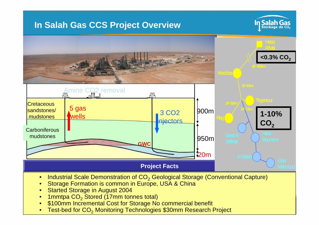
Satellite Imagery
Data collection since pre-injection
� Envisat and Radarsat2 key images used
� Inversion by a number of research partners
� Used for coupled Geomechanical Modelling
� Collected X-Band data in 2009
� Still assessing
� May use for horizontal deformation vector monitoring
� Satellite data may reduce seismic survey requirements

CO2 JIP Project 2010

CO2 JIP Project 2010
Krechba Field Structure
Seismic Line
Reservoir
900 metre Mudstone Top Seal

CO2 JIP Project 2010
2009 3D Seismic Survey Acquisition
2009 3D Survey
� Acquired April/May 2009
� Survey area ~ 156 km 2
� Extended cover to north – new shot lines (elsewhere same shot lines as 1997)
� Increased receiver line spacing to 160 m (480 m for 1997 survey)
� Vibroseis sweep 6–90 Hz (6–70 Hz 1997)

CO2 JIP Project 2010
Top C10.2 Reservoir/ Injection Horizon - Time
Top C10.2
wells:= injector= appraisal= producer
� Subtle anticline structure –steeper on eastern flank
� Numerous small-offset faults of varying orientations– Different
orientations from deeper Devonian faults

CO2 JIP Project 2010
Top C20.4 (Hot Shale) - Time
Top C20.4
wells:= injector= appraisal= producer
� Anticline structure progressively more subtle as move up through stratigraphy
� None of C10.2 faulting penetrates this stratigraphic level
� Surface shows NW-trending linear features in vicinity of CO2 injectors– 4D effect ?

CO2 JIP Project 2010
Carboniferous NW Linear Features: Kb-502 / Kb-5
1264 ms time slice
(textured by coherence)
X-line 1143
HU
KbKb--55KbKb--502502
KbKb--503503

CO2 JIP Project 2010
Carboniferous NW Linear Features: Kb-502z / Kb-5
X-line
1323
2009 X-line 1323: velocity push-down
1997 X-line 323: push-down??

CO2 JIP Project 2010
NW Linear Features: Alignment with Satellite Deform ation
Top C20.1
wells:= injector= appraisal= producer

CO2 JIP Project 2010
NW Linear Features: Alignment with Satellite Deform ation

CO2 JIP Project 2010 20
Comparison of Homogeneous & Multi-Layer Model
KB-502 Deformation from 11/29/03 to 1/12/08 (Sources are identical for both models)

CO2 JIP Project 2010
Coupled Geomechanical Model of the CO 2 Injection
XY
Z
X
-4000.
-3000.
-2000.
-1000.
0.
1000.
2000.
3000.
4000.
5000.
Y
-4000.-3000.
-2000.-1000.
0.1000.
2000.3000.
4000.5000.
V1L1G4
10 km10 km
4 km
FLAC3D Geomechanical Simulator
TOUGH2Multiphase Flow
Simulator
� Elastic properties of C10.2 sandstone consistent with laboratorymeasurements conducted by University of Liverpool (Faulkner andMitchell) at relevant confining stress level.
� Elastic properties of other layers estimated from vertical profiles of sonic logs ⇒ somewhat stiffer caprock (900-1800 m) and softer near surface layer (0 – 900 m)

CO2 JIP Project 2010
The Emerging Structural Model
How do we make sense of this?
R
R’
YP
T
F
75°
15°
15°
45°
45°
P, R, R’, Y = Riedel shearsT = Tension fracturesF = Fold axis
σ1
N
Deep-seated faults
propagating upwards
Minor faults
Expected fracture zones
1. We have a present-day strike-slip stress regime with max stress NW-SE
2. The Krechba anticline was formed in a Late Carboniferous NE-SW strike-slip stress regime

CO2 JIP Project 2010
4. The storage volume – 5 generations of grid
20x20 (500m x500m) areal grid, laterally homogeneous – based on KB-4 props
38 layers from surface down to Devonian (3km), 10800 active cells
1
2
3 4
5
2006 - Simulation test grid
2008 - JIP grid – too small
2008 - Grid III built in RMS 2009 - Grid IV built in R MS
2010 - Grid V built in Wellwhiz
descent of CO2-saturated brine after 500 years
338,000 active cellsStops below C10
Boundary of previous grid
New Grid – Grid_V3
50 x 40 x 3.5 kms150x150x22
From near ground surface to DevonianNew (k,phi) arrays
Image source Mike Goldwater: Auric Hydrates & Fracture
Technologies
Grid (UP) for Characterising Geomechanical Elastic Parameters
-500
-300
-100
100
300
500
700
900
1100
1300
0 0.05 0.1 0.15 0.2 0.25 0.3 0.35 0.4 0.45 0.5
Dep
th m
TV
D s
s
Pois R KB-4
KB-4 HU
KB-5 HU
KB-4 S20
KB-5 S20
KB-4 D70
KB-4 YM mod
Line 1
Line 2
Line 3
Line 4
Line 5
Line 6
series 2
Line 7
Line 8
Line 9
Series5
Series6
Series7
Series8
Series9
Series10
Series11
Series12
Series13
Series14
Series15
Series16
Series17
Series18
Series19
Series20
Series34
Series35
Series36
Series37
Series38
Series39
Series40
Series41
Series42
Series43
Series44
C20_7_VIS_HOTSHALE_RCB_BIG and Hotshale_base_map_RCB_BIG
Anhydrite_over_HUC_RCB_BIG and TOP_HUC_RCB_BIG
Top_Cret_Con_approx_RCB_BIG
RCB_Water_Table_Surface
RCB_Ground_Surface_BIG
C20_2_VIS_RCB_BIG
C20_1_VIS_RCB_BIG
C10_3_TOURN_RCB_BIG Top_Res_grd_C10_2_RCB_BIG
Copy of grid III but refined verticallyto better model variation in elastic parameters
150x150x63

CO2 JIP Project 2010
Co-Visualisation

CO2 JIP Project 2010
Key Lessons Learned – Krechba (1)
� Successful storage demonstrated to date– No anomalies noted except KB5
� Each storage site is unique but with similarities– Sahara Carboniferous vs. North Sea– Storage horizon, caprock and wellbore integrity all key issues
� Monitoring programme site specific– Cost effective technologies proven very effective
– Wellhead/annulus monitoring, tracers, shallow aquifer, satellite imagery
� 3D Seismic effective but costly– Need cheaper technology– Need better understanding of azimuthal velocity ana lyses– Need faster processing technologies
� Expect the unexpected– Satellite imagery unexpected success
– Results have changed understanding of subsurface plume migration
– Do not ignore unusual/non conventional technologies – Gravity, Electromagnetic, Microbiology
– Wellbore integrity issues� Need methods to quantify leakage/flux rates

CO2 JIP Project 2010
Key Lessons Learned – Krechba (2)
� Overburden as important as the storage reservoir– Coupled hydro-geomechanical modelling crucial for l ong term plume prediction
– Require very good overburden geomechanical and samp le data – not just storage horizon
– Fracture/fault characterisation critical
– CO2 plume migration heterogeneous – requires high resolu tion subsurface data to resolve
� Direct observation of CO 2 plume critical– Need observation wells - but costly
– Wellbore integrity/leakage issues
– Need integrated downhole monitoring suite
– Chemical monitoring and quantification – dissolved a nd Free CO 2
� Regular Quantitative Risk Assessment reviews crucia l– Allows for risks to be identified and mitigated/avo ided
– Need to develop long term risk profile understandin g
� We know more about CO 2 storage than we believe– A different application of currently available tech nologies
� Is it Rocket Science? I think not!!