Embed Size (px)
Citation preview

Title In-Process Monitoring and Adaptive Control inMicro Welding with a Single-Mode Fiber Laser
Author(s) KAWAHITO, Yousuke; KATAYAMA, Seiji
Citation Transactions of JWRI. 38(2) P.5-P.11
Issue Date 2009-12
Text Version publisher
URL http://hdl.handle.net/11094/10967
DOI
rights
5
Transactions of JWRI, Vol.38 (2009), No. 2Transactions of JWRI, Vol.38 (2009), No. 2
In-Process Monitoring and Adaptive Control in Micro Welding
with a Single-Mode Fiber Laser †
KAWAHITO Yousuke* and KATAYAMA Seiji**
Abstract
A fiber laser has excellent beam quality, enough to be applied for micro welding of electronics or automobile parts, and thus is regarded as a promising heat source for adaptive control since the laser peak power can be changed within a sub-micro-second period. This research was undertaken with the objective of obtaining a fundamental knowledge of in-process monitoring and adaptive control for the stable bead widths of full penetrations under the conditions that surround heat transfer or rapid change in welding speed when drastically changed in the micro welding of thin metal sheets with a continuous wave (CW) single-mode fiber laser beam. Concerning the surrounding conditions of heat transfer in bead-on-plate welding of a 0.1 mm-thick type 304 stainless steel sheet, the bead width was so influenced with or without aluminum heat sink that the bead width increased from 320 μm to 790 μm at 10 mm/s welding speed and 75 W laser power. It was found that the heat radiation was sensitive to such a rapid growth of the molten pool diameter. Moreover, the desired bead width was produced regardless of the existence of the heat sink by controlling the laser power adaptively on the basis of heat radiation intensity. As for welding speed in lap seam micro-welding of 0.1 mm-thick pure titanium, it was revealed that the geometry of the full penetration weld was drastically changed from narrow to wide, or to partial penetration during rapid deceleration in welding speed from 50 mm/s to 10 mm/s and the corresponding laser power of 75 W to 47 W. Prediction of the weld bead width on the bottom surface was difficult when utilizing monitoring of the heat radiation signal. Therefore, the designed stable full-penetration welds were made by controlling the laser power adaptively according to the heat radiation signal in order to adjust the weld bead width on the laser-irradiated surface to the target weld geometry affected by thermal storage. Consequently, it was confirmed that adaptive control was effective with drastic changes of surrounding conditions of heat transfer or welding speed during lap seam micro-welding process with a CW single-mode fiber laser beam.
KEY WORDS: (In-process monitoring), (Adaptive control), (Micro welding), (Single-mode fiber laser)
1. Introduction Laser micro-welding has been applied not only in
precision micro-assemblies but also in device sealing in electronics and automobile industries1, 2). Package sealing in precision devices or battery cells requires not only higher strength but also prevention of air penetration or transmission. In particular, at the corners in micro sealing, the welding speed and laser power are changed so drastically that weld penetration can be easily changed from the keyhole-type to the quasi-keyhole-type or the heat-conduction-type and vice versa, leading to the formation of a weld with burn-through, shallow penetration or a non-bonded part. In-process monitoring and adaptive control are supposed to be extremely useful procedures for stable laser micro welding.
Moreover, a fiber laser has been regarded as a promising heat source for adaptive control, since the laser peak power can be changed within the sub-microsecond
period by laser diode (LD) pumping. Recently, several papers have been devoted to research on in-process monitoring and advanced adaptive control technology in laser welding3–8). With respect to in-process monitoring, it was reported that the infrared radiation signal was representative of the surface temperature and the threshold between pure conduction heating and the vapor/plasma regimes was detected by a photodiode 3). Furthermore, concerning adaptive control, it was demonstrated that the maximum penetration could be maintained by a two-color imaging system to control weld pool temperature just below vaporization in heat-conduction type welding4). However, no studies have been devoted to such monitoring and adaptive control in lap seam micro welding with a CW single-mode fiber laser.
In this research, lap seam micro welding of thin metal sheets was exploited to produce a fully penetrated
Transactions of JWRI is published by Joining and Welding Research Institute, Osaka University, Ibaraki, Osaka 567-0047, Japan
† Received on December 18, 2009 * Associate Professor ** Professor
6
In-Process Monitoring and Adaptive Control in Micro Welding with a Single-Mode Fiber Laser
weld with a desired bead width, using a CW single-mode fiber laser beam under the conditions when the surrounding state of heat transfer or welding speed was changing drastically. The heat radiation from the laser-irradiated area was measured from the coaxial direction of the incident fiber laser beam. The heat radiation intensity was evaluated as an in-process monitoring signal for a molten pool on the laser-irradiated surface or the weld bead width on the bottom surface. Moreover, the laser peak power was controlled according to the heat radiation signal in order to produce the full-penetration weld with a desired bead width in spite of surrounding conditions of heat transfer or rapid change of welding speed. 2. Experimental set-up and materials used
A commercially available Type 304 stainless steel and pure titanium were the materials used for in-process monitoring and adaptive control concerning surrounding conditions of heat transfer or rapid change in welding speed, respectively. The samples were 0.1 mm thick and 5 mm wide.
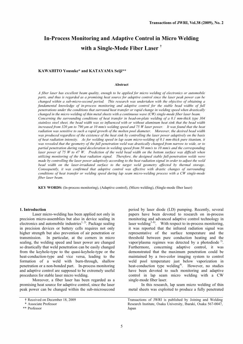
Lap seam micro-welding was carried out with a 100 W single-mode fiber laser of 1090 nm wavelength under 25 L/min argon shielding gas, as shown in Fig. 1. The 5.3 mm diameter-collimated beam with 0.3 mrad divergence is focused into a 50 μm spot diameter by optics of 150 mm focal length. The laser peak power is changeable at 1 ms intervals according to the external voltage. The heat radiation and the reflected laser beam from the laser-irradiated area are separated by a diffractive grating and are measured by photo diode sensors. For adaptive control, the laser peak power is controlled during irradiation according to heat radiation in order to stably produce a full-penetration weld with a predetermined bead width on the laser-irradiated or bottom surface. One cycle of the adaptive control consists of in-process monitoring with 1-MHz sampling, estimation for laser welding conditions and 1-ms-rapid change in the laser peak power and the cycle time is allowed to be more than 2 ms. In addition, the high-speed video observation of molten pool behavior is taken at a frame rate of 10 000 frames/s from the angle of
15◦ to the sample surface under the illumination of a 22 mW He–Ne laser.
3. Experimental results and discussion 3.1 Full penetration weld and in-process monitoring influenced by surrounding conditions of heat transfer
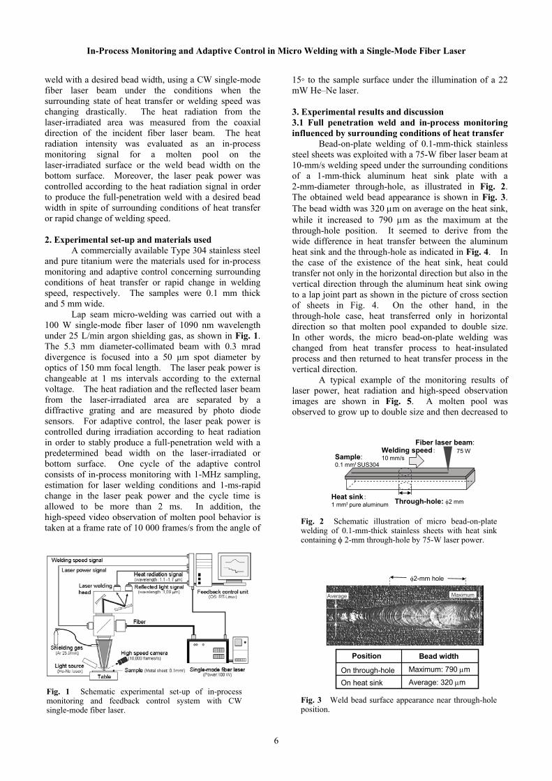
Bead-on-plate welding of 0.1-mm-thick stainless steel sheets was exploited with a 75-W fiber laser beam at 10-mm/s welding speed under the surrounding conditions of a 1-mm-thick aluminum heat sink plate with a 2-mm-diameter through-hole, as illustrated in Fig. 2. The obtained weld bead appearance is shown in Fig. 3. The bead width was 320 m on average on the heat sink, while it increased to 790 m as the maximum at the through-hole position. It seemed to derive from the wide difference in heat transfer between the aluminum heat sink and the through-hole as indicated in Fig. 4. In the case of the existence of the heat sink, heat could transfer not only in the horizontal direction but also in the vertical direction through the aluminum heat sink owing to a lap joint part as shown in the picture of cross section of sheets in Fig. 4. On the other hand, in the through-hole case, heat transferred only in horizontal direction so that molten pool expanded to double size. In other words, the micro bead-on-plate welding was changed from heat transfer process to heat-insulated process and then returned to heat transfer process in the vertical direction.
A typical example of the monitoring results of laser power, heat radiation and high-speed observation images are shown in Fig. 5. A molten pool was observed to grow up to double size and then decreased to
Fig. 1 Schematic experimental set-up of in-process monitoring and feedback control system with CW single-mode fiber laser.
Welding speed:10 mm/s
Fiber laser beam:
Through-hole: 2 mmHeat sink:1 mmt pure aluminum
Sample:0.1 mmt SUS304
75 W
Fig. 2 Schematic illustration of micro bead-on-plate welding of 0.1-mm-thick stainless sheets with heat sink containing 2-mm through-hole by 75-W laser power.
2-mm hole
Position
On through-holeOn heat sink
Bead widthMaximum: 790 m
Average: 320 m
Average Maximum
Fig. 3 Weld bead surface appearance near through-hole position.

7
Transactions of JWRI, Vol.38 (2009), No. 2Transactions of JWRI, Vol.38 (2009), No. 2
the normal size when the laser beam spot passed the through-hole position. Then the reflected light was kept almost constant in spite of the through-hole position. However, the heat radiation intensity increased more than twice as high as that measured on the aluminum heat sink, and then dropped down to the normal level measured on the heat sink.
Subsequently the relationship between the heat radiation and the surface molten pool diameter is plotted in Fig. 6. It was found that the heat radiation intensity was in proportion to the molten pool diameter perpendicular to the welding direction. Therefore, the
heat radiation was so sensitive to expansion and contraction of the molten pool that it was useful as an in-process monitoring signal for detecting the surface molten pool diameter. 3.2 Adaptive control for stable production of weld bead influenced by surrounding conditions
In order to stably produce the desired bead width, the laser peak power was controlled according to the flow chart shown in Fig. 7. The laser peak power was dropped down by 8 W when the heat radiation intensity exceeded 16.8 W, or the laser peak power was raised up by 8 W when the heat radiation was below 16.2 W. Under the other conditions, the laser peak power was maintained at the current state. Here, the heat radiation intensities from 16.2 W to 16.8 W indicated a 430-m molten pool diameter as shown in Fig. 7. The cycles of the adaptive control are 2 ms, 4 ms, 8 ms, 20 ms and 40 ms.
A typical experimental result under the adaptive control at 2 ms cycle is shown in Fig. 8. The lower photos demonstrate that the molten pool size was almost constant in spite of the through-hole. Then the laser peak power showed such rapid and complicated changes that the heat radiation intensities were kept from 13.4 W to 19W on the through-hole position.
The appearance of the obtained weld bead is shown in Fig. 9. The bead width was 320 m on the average on the heat sink, while the bead width was about 430 m at the maximum on the through-hole position. Therefore, it was found that that adaptive control was effective for the suppression of the bead width expansion induced by the -mm through-hole.
Finally, the relationship between the cycle of the adaptive control and the maximum bead width is plotted in Fig. 10. It was found that the cycle below 10 ms produced the bead width of about 430 m on the
Fiber laser beam
Heat sink:Al
SUS304
Heat
Fiber laser beam
Al
SUS304
2 mm hole
SUS304
Al 30 m
(a) Heat transferon heat sink
(b) Heat transfer on through-hole
Molten pool Molten pool
Fig. 4 Schematic illustration of heat transfer on heat sink and at through-hole position.
Fig. 5 Schematic illustration of heat transfer on heat sink and at through-hole position.
Fig. 6 Relationship between heat radiation and surface molten pool diameter perpendicular to welding.
Stop of adaptive control
Heat radiation 16.8 W
Laser irradiation>1.5 ms
Heat radiation 16.2 W
YES
Increase by 8 W laser peak power
Decrease by 8 W laser peak power
Keep laser peak power
NO
YES
NO
YES
NO
Start of adaptive control
Fig. 7 Flow chart of adaptive control for stable production of weld bead width in micro bead-on-plate welding influenced by surrounding conditions.

8
In-Process Monitoring and Adaptive Control in Micro Welding with a Single-Mode Fiber Laser
through-hole position. Taking into account that the laser beam spot took 0.2 s to pass through the through-hole position, effective adaptive control required more than twenty controls of the laser peak power. On the other hand, a few controls of the laser power indicated such a poor feasibility that the bead width was almost the same as that without the adaptive control.
3.3 Full penetration weld and in-process monitoring at rapid deceleration of welding speed
Full-penetration welding for the purpose of producing the weld with a constant bead width on the bottom surface was exploited at 50-ms-rapid deceleration of welding speed from 50 mm/s to 10 mm/s in micro lap seam welding of 0.1 mm-thick pure titanium sheets. The laser power at the high welding speed is 75 W, which is decreased to 47 W at the start of the deceleration. Figure 11 shows the top and bottom surface appearances of a weld bead subjected to the decrease in welding speed and the corresponding increase in laser power. The weld bead width on the laser-irradiated surface expanded from 0.35 mm to 0.65 mm as the welding speed was decreased from 50 mm/s to 10 mm/s. However, the weld bead on the bottom surface disappeared partly during the deceleration and then increased to 0.24 mm in width which was almost the same width as at 50-mm/s welding speed. The ratio of the bottom surface bead width to the laser-irradiated top surface bead width is plotted as a function of time relative to the starting point of the rapid deceleration in Fig. 12. Full penetration was changed to partial penetration at the initiation stage of the speed decrease. Moreover, it was revealed that the weld penetration geometry was also changed drastically from keyhole-type to quasi-keyhole-type or heat-conduction-type penetration, judging from the extreme ratio decrease from 0.7 before the deceleration to 0.15.
Fig. 8 Monitoring results in micro bead-on-plate welding under adaptive control for suppression of bead expansion induced by surrounding conditions.
Fig. 9 Weld bead surface appearance near through-hole position under adaptive control with 2-ms cycle.
Fig. 10 Relationship between cycle of adaptive control and weld bead.
Fig. 11 Both surface appearances of weld beads produced at welding speed deceleration in laser lap seam welding.
Fig. 12 Change in weld penetration geometry during deceleration of welding speed.
9
Transactions of JWRI, Vol.38 (2009), No. 2Transactions of JWRI, Vol.38 (2009), No. 2
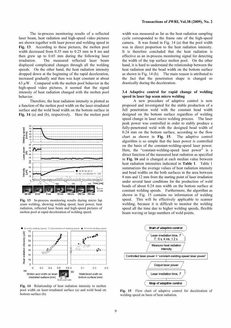
The in-process monitoring results of a reflected laser beam, heat radiation and high-speed video pictures are shown together with laser power and welding speed in Fig. 13. According to these pictures, the molten pool width decreased from 0.35 mm to 0.25 mm in 8 ms and then grew up to 0.65 mm during the following laser irradiation. The measured reflected laser beam displayed complicated changes through all the welding speeds. On the other hand, the heat radiation intensity dropped down at the beginning of the rapid deceleration, increased gradually and then was kept constant at about 63 W. Compared with the molten pool behavior in the high-speed video pictures, it seemed that the signal intensity of heat radiation changed with the molten pool behavior.
Therefore, the heat radiation intensity is plotted as a function of the molten pool width on the laser-irradiated surface and the weld bead width on the bottom surface in Fig. 14 (a) and (b), respectively. Here the molten pool
width was measured as far as the heat radiation sampling cycle corresponded to the frame rate of the high-speed camera. It was found in Fig. 14 (a) that the pool width was in direct proportion to the heat radiation intensity. It is therefore concluded that the heat radiation is effective as an in-process monitoring signal for detecting the width of the top surface molten pool. On the other hand, it is hard to understand the relationship between the heat radiation and the bead width on the bottom surface as shown in Fig. 14 (b). The main reason is attributed to the fact that the penetration shape is changed so drastically during the deceleration. 3.4 Adaptive control for rapid change of welding speed in laser lap seam micro welding
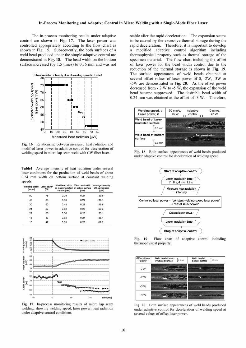
A new procedure of adaptive control is now proposed and investigated for the stable production of a full penetration weld with the constant bead width designed on the bottom surface regardless of welding speed change in laser micro welding process. The laser peak power was controlled in order to stably produce a fully-penetrated weld with the designed bead width of 0.24 mm on the bottom surface, according to the flow chart as shown in Fig. 15. The adaptive control algorithm is so simple that the laser power is controlled on the basis of the constant-welding-speed laser power. Here, the “constant-welding-speed laser power” is a direct function of the measured heat radiation as specified in Fig. 16 and is changed at each median value between heat radiation intensities indicated in Table 1. Table 1 summarizes the average values of heat radiation intensity and bead widths on the both surfaces in the area between 8 mm and 12 mm from the starting point of laser irradiation under several laser conditions for the production of weld beads of about 0.24 mm width on the bottom surface at constant welding speeds. Furthermore, the algorithm as shown in Fig. 15 contains no information of welding speed. This will be effectively applicable to scanner welding, because it is difficult to monitor the welding speed all the time due to higher welding speeds, flexible beam waving or large numbers of weld points.
Fig. 13 In-process monitoring results during micro lap seam welding, showing welding speed, laser power, heat radiation, reflected laser beam and high-speed pictures of molten pool at rapid deceleration of welding speed.
Fig. 14 Relationship of heat radiation intensity to molten pool width on laser-irradiated surface (a) and weld bead on bottom surface (b).
Fig. 15 Flow chart of adaptive control for deceleration of welding speed on basis of heat radiation.
10
In-Process Monitoring and Adaptive Control in Micro Welding with a Single-Mode Fiber Laser
The in-process monitoring results under adaptive control are shown in Fig. 17. The laser power was controlled appropriately according to the flow chart as shown in Fig. 15. Subsequently, the both surfaces of a weld bead produced under the simple adaptive control are demonstrated in Fig. 18. The bead width on the bottom surface increased (by 1.5 times) to 0.36 mm and was not
stable after the rapid deceleration. The expansion seems to be caused by the excessive thermal storage during the rapid deceleration. Therefore, it is important to develop a modified adaptive control algorithm including thermophysical property such as thermal storage of the specimen material. The flow chart including the offset of laser power for the bead width control due to the reduction of the thermal storage is shown in Fig. 19. The surface appearances of weld beads obtained at several offset values of laser power of 0, -2W, -3W or -5W are demonstrated in Fig. 20. As the offset power decreased from - 2 W to -5 W, the expansion of the weld bead became suppressed. The desirable bead width of 0.24 mm was obtained at the offset of -3 W. Therefore,
Fig. 16 Relationship between measured heat radiation and modified laser power in adaptive control for deceleration of welding speed in micro lap seam weld with CW fiber laser. Table1 Average intensity of heat radiation under several laser conditions for the production of weld beads of about 0.24 mm width on bottom surface at constant welding speeds.
Fig. 17 In-process monitoring results of micro lap seam welding, showing welding speed, laser power, heat radiation under adaptive control conditions.
Fig. 18 Both surface appearances of weld beads produced under adaptive control for deceleration of welding speed.
Fig. 19 Flow chart of adaptive control including thermophysical property.
Fig. 20 Both surface appearances of weld beads produced under adaptive control for deceleration of welding speed at several values of offset laser power.

11
Transactions of JWRI, Vol.38 (2009), No. 2Transactions of JWRI, Vol.38 (2009), No. 2
it is important to consider the adaptive control algorithm including thermophysical property of the specimen material.
The adaptive control algorithm including the above-mentioned thermophysical property of the martial is simply applied to the above-mentioned welding speed acceleration in lap seam micro welding. Here, a laser micro lap seam weld was formed at 50-ms-rapid acceleration of welding speed from 10 mm/s to 50 mm/s. Then the laser power at the low welding speed and the other one is 47 W and 75 W, respectively. Figure 21 demonstrates these welding results without and with the adaptive controlled laser power with 5-W offset power. Without the adaptive control, the weld bead width on the laser-irradiated surface became narrow from 0.65 mm to 0.35 mm as the welding speed was raised. The appearances of the bottom surfaces show that the weld bead became enlarged partly during acceleration of the welding speed. On the other hand, the desirable bead with of 0.24 mm was obtained at the offset of 5 W regardless of the rapid acceleration. Therefore, it was confirmed that the developed adaptive control algorithm was effective for not only rapid deceleration but also rapid acceleration of welding speed.
5. Conclusions
In-process monitoring and adaptive control has been developed for the micro-welding process of thin metal sheets with a CW single-mode fiber laser beam. The effectiveness of in-process monitoring for a molten pool and the feasibility of adaptive control for the stable production of bead width in spite of surround heat transfer or rapid change in welding speed were evaluated. The results obtained are as follows:
Concerning full penetration weld and in-process monitoring influenced by surrounding heat transfer (1) It was found that the weld bead on the aluminum heat sink including 2-mm through-hole was so influenced by surrounding conditions that the bead width increased from 320 m to 790 m at the maximum. (2) The heat radiation intensity was in proportion to the molten pool diameter and it was useful for detecting the surface molten pool in real time.
Concerning adaptive control for stable production of weld bead influenced by surrounding conditions
(3) Adaptively-controlled peak power in micro welding with CW fiber laser was beneficial to stable production with the desired bead width on the laser-irradiated surface, regardless of the existence of the heat sink plate. (4) The cycle of the adaptive control below 10 ms was effective for the suppression of the bead width expansion induced by the 2-mm through-hole.
Concerning full penetration weld and adaptive control at rapid deceleration of welding speed (5) The rapid deceleration in welding speed led to a partially-penetrated weld and drastic changes in full-penetration weld geometry under this welding condition. (6) The heat radiation intensity measured from the laser-irradiated area was useful as an in-process monitoring signal for detecting the molten pool size on the laser-irradiated surface. However, it was not easy to predict the weld bead width on the bottom surface by monitoring the heat radiation from the laser-irradiated surface due to the formation of partial penetration or the change of penetration shape.
Concerning full penetration weld and in-process monitoring at rapid deceleration of welding speed (7) The designed stable full-penetration welds were made by the laser power adaptively-controlled according to the heat radiation signal in order to adjust the weld bead width on the laser-irradiated surface to the target weld penetration geometry affected by thermal storage in spite of changes of welding speed. (8) It was confirmed that adaptive control was effective for drastic changes of welding speed during lap seam micro-welding process with a CW single-mode fiber laser beam.
Acknowledgements
The authors would like to acknowledge Mr. Masaharu Kawasaki and Mr. Terumasa Ohnishi, graduate students of Mechanical Engineering Course of Osaka University, for their experimental helps.
References
1) T. Sakurai and Y. Nakagawa: Proc. Conf. on 62nd Laser Materials Processing (Osaka) 2003 pp. 102-110.
2) H. Fukuda, K. Ito, H. Tamaki, Y. Yamauchi and T. Amazutumi: SANYO Tech. Rev. 1995 28 pp.112-118.
3) F. Bardin, D. Delage, D. Lepretre, L. Bacinello, W. Knapp, N. Dumont and F. Durand: Proc. of LAMP (Osaka) 2002 pp. 69-72.
4) F. Bardin, S. Morgan, S. Williams, R. McBride, A. J. Moore, J. D. C. Jones and D. P. Hand: J. Appl. Opt. 2005 44 pp.6841-6848.
5) S. Postma, R. G. K. M. Aarts, J. Meijer and J. B. Jonker: J. Laser Appl. 2002 14 pp.210-214.
6) C. Begger and F. O. C. Olsen: J. Laser Appl. 2003 15 pp.19-24.
7) A. Sun, E. K. Jr. Asibu and M. Gartner: J. Laser App. 2000 14 pp.114-121.
8) Y. Kawahito and S. Katayama: J. Laser Appl. 2005 17 pp.30-37.
Fig. 21 Both surface appearances of weld beads made with and without adaptive control for acceleration of welding speed with offset of laser power.


