Embed Size (px)
Citation preview

In-plane retro�tting of masonry structures by usingGFRP strips in the BedjointsFathollah Osmanzadeh
Sahand University of TechnologyElshan Ahani ( [email protected] )
Shanghai Jiao Tong University https://orcid.org/0000-0002-8483-6547Behzad Rafezy
Sahand University of TechnologyMir Naghi Mousavi
Sahand University of Technology
Research Article
Keywords: Masonry walls, Retro�tting, Seismic behavior, GFRP strips, Simpli�ed micro modeling
Posted Date: August 17th, 2021
DOI: https://doi.org/10.21203/rs.3.rs-711691/v1
License: This work is licensed under a Creative Commons Attribution 4.0 International License. Read Full License

1
In-plane retrofitting of masonry structures by using GFRP strips in the bedjoints 1
d1, Mir Naghi Mousavic1, Behzad Rafezyb*1Elshan Ahani, a1Fathollah Osmanzadeh 2
1Faculty of Civil Engineering, Sahand University of Technology, Sahand New Town, Tabriz, East Azerbaijan Province, 3
51335/1996, Iran 4
Abstract 5
Many unreinforced masonry structures were vulnerable in the past earthquakes and required retrofitting. However, the 6
vulnerability of masonry structures could solve by providing numerous retrofitting approaches, scarcity of appropriate methods 7
that may provide a solution for the historical masonry structures with lesser effects on their façade is vehemently sensible. In this 8
study, two one-third scale masonry wall specimens made by clay bricks were tested under constant vertical and cyclic lateral 9
loading. The specimens consist of an unreinforced wall and a wall retrofitted by GFRP strips. This study investigates the seismic 10
behavior of unreinforced masonry walls before and after using GFRP strips on their bedjoints. To this purpose, various patterns 11
of using GFRP strips have been studied by simplified micro-modeling. The consequence indicates that the proposed retrofitting 12
technique could improve the lateral strength and stiffness of the unreinforced masonry wall along with a considerable increase in 13
the energy dissipation and ductility content, which leads to making a change in the behavior of the wall from brittle to ductile 14
failure. The proposed method could apply to the modern historical structures in which cement mortar has been used as an 15
adhesive between the masonry layers. 16
Keywords: Masonry walls; Retrofitting, Seismic behavior; GFRP strips; Simplified micro modeling. 17
1- Introduction 18
A large percentage of the existing buildings in the world have made of unreinforced masonry (URM) walls, many of which have 19
not been designed by seismic codes. Manifested reports from the earthquakes in the past 50 years demonstrated that the 20
vulnerability of URM structures to seismic excitations is much more than other types of structural systems (McGuire and 21
Leyendecker, 1974; NAHB Research Center, 1994; D’Ayala, 2013; NZSEE Part-C8, 2017; Fabbrocino et al., 2019). Due to 22
a M.Sc. Graduate of Structural Engineering, Sahand University of Technology, P.O. Box 51335/1996, Sahand New
Town, Tabriz, Iran, Email: [email protected] b* M.Sc. Graduate of Structural Engineering, Sahand University of Technology, P.O. Box 51335/1996, Sahand New
Town, Tabriz, Iran, (corresponding author), Email: [email protected] c Associate Professor of Structural Engineering, Department of Civil Engineering, Sahand University of
Technology, P.O. Box 51335/1996, Sahand New Town, Tabriz, Iran, Email: [email protected] d M.Sc. Graduate of Structural Engineering, Sahand University of Technology, P.O. Box 51335/1996, Sahand New
Town, Tabriz, Iran, Email: [email protected]
2
devastating earthquakes, many URM structures were thoroughly demolished (NAHB Research Center, 1994; Anagnostopoulos et 23
al., 2004; D’Ayala and Paganoni, 2011; Dizhur et al., 2011; NZSEE Part-C8, 2017). This is while the survived URM structures 24
are severely damaged or exposed to failure (D’Ayala and Paganoni, 2011; Dizhur et al., 2011; Bostenaru-Dan et al., 2013; 25
Papayianni, 2015; Cannizzaro et al., 2017). Many of these structures are monumental buildings that were of value and could be 26
an attraction point for centuries. The ingredients used as an adhesive between the layers of the masonry units in many historical 27
buildings were lime mortar. From the initial decades of the 20th Century, lime mortars used in masonry structures were gradually 28
replaced by cement mortars (Gerns and Wegener, 2003), congruity of which is more than formerly used mortar layers. This issue 29
leads to the construction of monolithic masonry structures with higher altitudes, the susceptibility of which to lateral loads is even 30
more than the preceding. The brittle behavior of masonry units and discontinuity of load-bearing elements (Calvi et al., 2004; Lin 31
et al., 2016) make these structures more vulnerable against lateral loads and oblige the URM walls to react as the only load-32
bearing system against seismic loads which barely survive. Thus almost every URM wall requires to considered for probable 33
retrofitting methods with lesser expenses and more efficacies. In the current study, a different method of retrofitting for the 34
modern historical masonry structures introduced. 35
Numerous experimental (Konthesingha et al., 2013; Wang et al., 2016; Knox et al., 2018; Arslan and Celebi, 2019) and analytical 36
(Chaimoon and Attard, 2007; Dhanasekar and Haider, 2008; Senthivel and Lourenço, 2009; Dolatshahi and Aref, 2011; Abdulla 37
et al., 2017) researches have been performed to evaluate the seismic behavior of masonry walls. Masonry walls are the only 38
resisting elements against earthquakes in unreinforced masonry buildings exposed to unpredicted lateral loads. Several handy 39
techniques in past decades are proposed to improve the seismic performance of existing URM walls. The prevailing retrofitting 40
techniques could be categorized but not limited to surface treatment like Ferro cement, shotcrete, etc. (Tasnimi and Rezazadeh, 41
2012; Lin et al., 2016; Shabdin et al., 2018), grout injection (Dadras et al., 2019; Doran et al., 2019; Ferreira et al., 2019), 42
external reinforcement (FEMA 172; Borri et al., 2009; Corradi et al., 2019) and center coring (FEMA 172; Dadras et al., 2019; 43
Paret et al., 2019). Several researchers discussed the disadvantages of these methods, like decrease in necessary space (ElGawady 44
et al., 2004; Cannizzaro et al., 2017), increase in structural mass (ElGawady et al., 2004; Cannizzaro et al., 2017; Ferreira et al., 45
2019) and the loss of architectural facades (ElGawady et al., 2004; Papayianni, 2015; Dadras et al., 2019). Hence, in recent 46
decades, some researchers are concentrated on retrofitting structures by using Fiber Reinforced Polymers (FRP). The advantages 47
of using FRP polymers are their high mechanical strength, low weight, and ease of application (Wang et al., 2017). Externally 48
bonded FRP strips used on the masonry walls increase the tensile and shear capacity, ductility, and lateral strength during the 49
earthquake. Many researchers have studied retrofitting of the masonry walls by using different FRP patterns (Capozucca, 2010; 50
Luccioni and Rougier, 2011; Santa-Maria and Alcaino, 2011; Kalali and Kabir, 2012a; Kalali and Kabir, 2012b). On the other 51
hand, the high cost of FRP materials which is about ten times that of structural steel disadvantage the use of FRP in the building 52
industry (Burgoyne, 2009; and Sarker et al., 2011) unless it is used in historical monuments which have priceless value and the 53

3
utilizing amount is managed. Using FRP conveys executive difficulties and an increase in expenses. In the current study, the 54
strips of FRP used inside the bedjoints of the wall, which to some extent decline the complicated instruction of using FRP in 55
structural systems. FRP materials are liable to shear loads (Burgoyne, 2009) that make these substances sensitive to the sharp and 56
pointy beds. Hence in the prevailing study, the bed for these materials prepared with more accuracy, and the use of these 57
materials in tension was controlled by numerical simulations before experimental studies. The utilization of FRP as a structural 58
instrument facilitates many difficulties in the building industry; however, instruction deficiencies for manipulating these 59
materials in design codes and standards are comprehensively tangible. Many premier standards consist of, but not limited to FIB 60
24 (2003), ACI 369R (2011), and ACI 562M (2013), have provided instruction for rehabilitation and/or retrofitting of RC 61
structures. The rehabilitation procedures of using FRP materials proffered by ACI 562M (2013) mostly referred to ACI 440.2R 62
(2008), which do not cover the retrofitting procedures of masonry structures. FIB 24 (2003) confines the considerable extent of 63
the retrofitting process with FRP to RC columns. En-1998-3 (2005) may consider FRP as valid retrofitting material for existing 64
structures including masonry if it is used as a ring that wrapping the damaged or vulnerable to damaged elements. FEMA 172 65
(1992) proposed numerous retrofitting techniques for existing URM walls, including increasing the shear capacity by adding 66
elements on the sides of the walls, filling the openings with appropriate elements, and using center coring. These methods do not 67
satisfy the proposed requirements of Standards for the Treatment of Historic Properties with Guidelines for Preserving, 68
Rehabilitating, Restoring & Reconstructing Historic Buildings (1995) and plagiarize the 36 CFR 68 (2012) law for historic 69
masonry structures. Utilization of FRP as a retrofitting element for existing steel, reinforced masonry, and reinforced concrete 70
structures are provided and consented by FIB 14 (2001), CAN/CSA-S806 (2012), CAN/CSA-S6 (2006), and FEMA 308 (1998). 71
While many standards straightly related to unreinforced masonry structures such as FEMA P774 (2009) and ACI 530 (2011) 72
have not considered FRP as an acceptable material for retrofitting of masonry structures. However, detailed information about the 73
retrofitting procedure of historical buildings are provided by ASCE 41 (2006), only from the indirect statement sum-up of ASCE 74
31 (2003) and ASCE 41 (2006), it can be deduced use of FRP to retrofitting of existing URM walls could take into consideration 75
whereas no principle for the using procedure presented. Hence, the requirement for studying the effects of FRP for both URM 76
and RM walls may be tangible. 77
Due to the different properties of mortar joints, masonry walls are considered as non-homogeneous parts. Hence, modeling of 78
masonry structures due to anisotropy of the units, the dimension of the masonry units, joint width, material properties of the 79
masonry units and mortar, the arrangement of bed joints and head joints, and quality of the working is considerably formidable 80
(Lourenço, 1994). Property of the constituent materials that affect the failure mode of the masonry walls could be in diagonal, 81
sliding along the mortar joints, toe crushing, or rocking. The test outcomes of numerous retrofitted walls with FRP polymers 82
demonstrated that a wide variety of failure modes consist of cracking of masonry in tension, crushing of masonry in compression, 83
shear-sliding of masonry, the fiber-reinforced composite failure, delamination of FRP, or a combination of them would take 84

4
place. In many tests, the FRP strips glued to historic clay bricks with a weak clay surface, which leads to the delamination of FRP 85
as a dangerous mechanism of brittle failure (Capozucca, 2010). Sometimes delamination of FRP strips from masonry walls 86
before the formation of failure makes the strips inert in the retrofitting process. In this paper, the FRP strips placed inside the 87
grooves didn't separate from the masonry wall before the failure. 88
Since the use of mortar in the building industry and masonry structures initiated from the early 1920s (Gerns and Wegener, 89
2003), some of the modern historical buildings, which are not older than 100 years and constructed by cement mortar as a 90
replacement for lime mortar could retrofit with this method. The mechanism of resistance in shear depends on the geometry of 91
masonry panels, boundary conditions, the magnitude of the vertical loads and, characteristics of the interface bond between 92
masonry units and mortar (Capozucca, 2011). Many of the historical monuments are consist of masonry walls that playing a 93
crucial role in a nation as the concept of culture and tourism. Seismic vulnerability evaluation of these buildings is always one of 94
the most significant issues in civil engineering. Hence they should retrofit by methods that won’t affect the appearance and 95
architecture besides the increase in the strength and ductility. Due to the complexity of the geometry, these buildings could not 96
retrofit by ordinary methods. In this study, the retrofitting of masonry walls that were consist of the vertical and lateral load-97
bearing elements have taken into account by using a particular layout of FRP polymers. This method could use for retrofitting of 98
the walls of historical masonry structures, which shall have diminutive effects on the façade of their well-formed edifices. The 99
mansion of Urmia municipality, the former palace of Tabriz municipality (Sa’at Tower), Stanley Dock Tobacco Warehouse of 100
Liverpool, Monadnock Building of Chicago, and Sheikh Safi al-Din Khānegāh and Shrine Ensemble of Ardabil are the samples 101
with historical values which could retrofit with the proposed method. This research is an endeavor to improve the integrity of 102
modern historical masonry structures by retrofitting them with the aid of GFRP strips which leads to the lesser interventions in 103
their façade and residual weight of the modified structure. 104
2- Research Significance 105
Retrofitting brick walls with traditional methods has many executable problems, including considering architectural changes that 106
are not feasible in many cases. The suitable physical and mechanical characteristics of FRP, which consist of lightweight, high 107
strength to weight ratio, high strength in tension, moisture resistance, flexibility, durability, high stability, and corrosion 108
resistance, have encouraged researchers to apply it. Most recent studies have dedicated to fixing FRP strips on masonry walls 109
either vertically or horizontally (Marcari et al., 2007; Capozucca, 2010; Gattulli et al., 2017; Reboul et al., 2018). However, the 110
applied methods that have an essential value in historical structures somehow inflict the façade. The use of FRP inside the 111
bedjoints, which is the concentration point of the current study, may somehow resolve the problem. Since the historical structures 112
are old and the bricks may not be in a row on out of plane direction or the first layer of bricks may be weathered, they do not 113
stick well and could be the cause of detachment of the FRP strips (Prakash and Alagusundaramoorthy, 2008; Grande et al., 2013; 114

5
Marcari et al., 2013). The problem referred to the inappropriate placement of the FRP strips in many cases. The modified placing 115
of the FRP strips considerably diminishes the separation and is considered a solution in this research. Retrofitting historical 116
masonries, the legacies of which should transmit to the future generation can impose substantial expenses on the nation. The high 117
outlay of the initial ingredients (Borri et al., 2009; Burgoyne, 2009; Sarker et al., 2011) and the preparation requirements 118
(Bostenaru-Dan et al., 2013; Dadras et al., 2019; Doran et al., 2019) may be the reason and proof for this allegation. Hence, an 119
alternative method that requires lesser preparation and a more straightforward application procedure is desirable. However, due to 120
the inexpensive value of the historical buildings satisfying the condition is hard to achieve. Therefore, using FRP inside the 121
bedjoints may decrease the complicated blueprints of retrofitting, the time, the cost, and could be applied by the workforce with 122
ease. According to numerous standards (Issue No. 376, 2007; NSET, 2009), main types of problems and basic damage patterns 123
observed during earthquakes in masonry buildings encompass non-integrity of wall and collapse of the building due to the rapid 124
cracking and disintegrating of the various parts and their brittle nature. In this regard, the studies could lead to proffering of better 125
outcomes. According to many studies, low ductility (NAHB Research Center, 1994; Tasnimi and Rezazadeh, 2012; NZSEE Part-126
C8, 2017; Dadras et al., 2019) and high weight (NZSEE Part-C8, 2017; Shabdin et al., 2018; Aghabeigi et al., 2020) accused as 127
the main reasons of failure in masonry. This is while most of the retrofitting procedures may somehow solve the ductility but 128
remain silent about the weight. Regarding the proffered facts, provision of a retrofitting method that increases the integrity with 129
lesser intervention in the façade and the final weight could be of high value. 130
3- Experimental Program 131
3-1- Test Setup and Instrumentation 132
The specimens were constructed on a concrete foundation with 80mm thickness, and the foundation connected to the rigid floor 133
with 12 high-strength bolts. A reinforced concrete beam was mounted on the walls to apply vertical and lateral loads. The 20kN 134
vertical load was applied by the 50kN actuator and placed on steel rolls upon the I section with direct contact to the RC beam. 135
These rollers expand the vertical load and avoid creating false hardness due to friction. The lateral cyclic load was applied by a 136
1000kN hydraulic actuator to the concrete beam. The reaction of the walls was undertaken by the rigid floor, which does not have 137
significant deformation under the lateral cyclic load. A 200kN load cell took place between the hydraulic actuator and the lateral 138
load system. The loading procedure initiated by applying vertical load with linear increasing amplitude, and then the lateral cyclic 139
load was applied. The lateral displacements of the walls under cyclic loading measured by LVDTs located on the upper sides of 140
the masonry wall. Two horizontal bars on each side of the test specimen were fixed to the loading plates on the rear and former 141
faces of the wall. The loading commenced by direct loading inducement of the actuator to the former face and the reverse loading 142
performed by engaging the horizontal loading bars to the rear loading plate. A detailed schematic of the test setup and the utilized 143
6
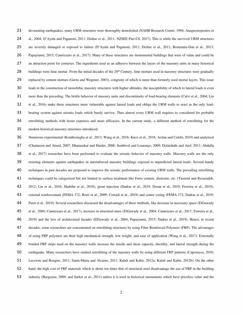
instruments for the loading procedure has provided in Fig. 1. The lateral loading procedure with increasing cyclic steps continued 144
until the failure of the specimens. The applied force-controlled loading pattern of the present study with 3kN steps has depicted in 145
Fig. 2. 146
147 Fig. 1 Experimental setup of test specimens; The particles in the schematic view are consist of (1) A 50kN actuator used for vertical loading 148
system, (2) Steel rolls located upon the I section, which expanding the vertical loading, (3) LVDTs located on both sides of the wall, which 149
measures lateral displacements of the walls during the loading procedure, (4) Vertical rebars, which indirectly applying the vertical load through 150
the vertical actuator, (5) Concrete foundation with 80mm thickness, (6) Sidebars that are controlling the out of plane excitations and thwarting the 151
overturning of the wall, (7) A 1000kN hydraulic actuator, which used for lateral loading system, (8) LVDT for measuring the out of plane 152
displacements of the walls under cyclic loading. 153
154
155 Fig. 2 Loading pattern consists of 24 force-controlled cycles in which increase in lateral load is 3kN for each step 156
3-2- Test Specimens 157
Because of the high expenses of fabricating experimental samples, two specimens have been mounted in the structural laboratory 158
of the Sahand University of Technology, while the rest of the studies to ascend the depth of research performed numerically. 159
-80
-60
-40
-20
0
20
40
60
80
1 10 19 28 37 46
Lo
ad
ing
(k
N)
Cycle No.

7
Experimental studies for assuring the prosperity of the proposed method, whereas numerical studies to excavate the efficiency of 160
that, were carried out. However, the provision of more accurate outcomes for complicated structures requires further excavation, 161
and this study is performed to evaluate the viability of the introduced method. Concerning the principles of BHRC (2005), the 162
width of loadbearing masonries could not be less than 200mm, and the length of them without tie columns could not exceed 163
6000mm. The maximum height of a masonry wall without tie beams should be less than 4000mm, accordingly. Since most of the 164
modern historical masonries, to some extent, resided inside these limitations, a masonry wall with a respective height, width, and 165
thickness of 3000mm, 5250mm, and 300mm was assumed as the prototype for this study. The selection criteria for evaluating the 166
unreinforced masonry and the dimension also reside within the constraining principles of En-1998-1 (2004). Concerning the 167
instrumental limitations and further execution costs, one-third scale models were constructed in the laboratory. Hence, the height, 168
width, and thickness of the selected wall specimens with the aspect ratio of 1.74 were 1000mm, 1740mm, and 100mm, 169
respectively. Because of the executive restrictions, a minute difference between the aspect ratios of the prototype and 170
experimental models took place. Despite the scaling of experimental specimens, the size of masonry units was retained intact. 171
Since the provided sizes for the masonry units are various, it could be hypothetically authenticated to use smaller units to acquire 172
the required scale for the research specimens. 173
The equilibrium equation of the unreinforced masonry (URM) was allocated to determine the equivalent required GFRP strips. 174
The hypothesis of prepared equilibrium equations of the unreinforced masonry (URM) was made the design rationale and needed 175
area of GFRP strips for retrofitting. The required GFRP strip amount on each layer according to the simplifying assumptions of 176
solving the equilibrium equation has been obtained, which was extracted according to the provided explanation of Fig. 3 and 177
presented in respectively explained Eq. (1) to Eq. (3) equations. 178

8
179
Fig. 3 Preparing equilibrium equation of masonry partial element for determining the retrofitting requirements of unreinforced masonry wall 180 V = {nbhγGm Eb ≥ Emnbh[ε(Eb − Em) + γGm] Eb < Em (1)
Where Eb and Em are elasticity modulus of masonry unit and mortar joint, b and h are the width and thickness of the masonry 181
units, n is the numbers of existing layers in equilibrium element, γ is the shear strain of the selected element, and Gm is the shear 182
modulus of mortar joint, respectively. The maximum amount of shear considering the nFs ≥ V inequality, where Fs is the 183
imposed tensile force of the GFRP strips located inside the bedjoints, according to Eq. (1), always took place when the elasticity 184
modulus of the masonry unit is more than its peer mortar joint. Correspondingly, the minimum design force for the assigned 185
strips may acquire according to Eq. (2). 186 Fs = bhγGm (2)
The minimum required area of GFRP strips by expanding Eq. (2) would lead to more operational relation as presented in Eq. (3). 187
As = bh γ2(1 + 𝜐𝑚) EmEs (3)
Table 1 Characteristics of experimental specimens 188
Specimens 2
Retrofitted Masonry Wall
Specimens 1
Unretrofitted Masonry Wall
Description
1000 X 1740 X 100 1000 X 1740 X 100 Height, Width and Thickness (mm)
1.74 1.74 Aspect Ratio (Width/Height)
10 10 Thickness of mortar joints (mm)
1/3 1/3 Cement/sand ratio of mortar
195.4⨉98.5⨉56.3 195.4⨉98.5⨉56.3 Masonry unit Size (mm)
14 None Number of GFRP Rows
10 None Thickness of GFRP strips (mm)
Assumptions:
(a) dx ≈ dy.
(b) Properties of the headjoints and
bedjoints assumed to be identical.
(c) Thickness of the joints
considered to be zero.
(d) Partial variation in internal
forces of equilibrium equation has
neglected.
(e) Unit sizes assumed to be
identical.
Equilibrium Equations:
∑𝐅𝐱 = 𝟎: Fx −∑fhini=1 +∑vbin
i=1 − Vxy = 0 identical sizes → Vxy = Fx − n. fh + n. vb
∑𝐅𝐲 = 𝟎: Fy −∑fbini=1 +∑vhin
i=1 − Vxy = 0 identical sizes→ Vxy = Fy − n. fb + n. vh
identical properties→ {n. fb = n. fh = nf n. vb = n. vh = nv → {Vxy = Fx − nf + nvVxy = Fy − nf + nv → 𝐅𝐱 = 𝐅𝐲 = 𝐅 If ∶ (Vxy = V) → 𝐕 = 𝐅 + 𝐧(𝐯 − 𝐟) In which {F 𝛂 Minimum strength of the masonry unit or mortar joint(v − f) 𝛂 Strength of the mortar joint F = min(EmεmA, EbεbA) A=bdx=bdy & εm=εb=𝜀→ F = nhbε.min (Em, Eb) f = Emεbh & v = Gmγbh

9
189
Masonry units made of clay are prevalent construction units in the Middle East. The average measured dimension for selected 190
units was 195.4⨉98.5⨉56.3mm. The average thickness of mortar joints is 10mm with water:cement:sand ratio of 1:2:6. The 191
studied wall specimens are consist of a bare wall and a wall retrofitted by 10mm width GFRP strips, which placed along the bed 192
joints on one side of the wall. In Table 1, the evaluated experimental models have demonstrated. Mechanical properties of 193
masonry walls are affected by the characteristics of the constituent elements (bricks and mortar), the workmanship, and the 194
interface interaction within the assemblage. The mechanical properties of bricks were determined by unidirectional compressive 195
and tensile tests. The mean compressive strength of ten specimens of masonry units was 9.20MPa, and the average flexural 196
strength of the bricks was 0.31MPa according to ASTM C67-11 (2011) test principles. The compressive and tensile test results of 197
the studied specimens are presented in Table 2. The standard test results of three (40×40×160mm3) flexural and six 198
(50×50×50mm3) compressive mortar samples, for 28 days curing, had an average strength of 4.10MPa and 33.21MPa, 199
respectively. The modulus of elasticity and the Poisson’s ratio of concrete beams located on the wall and the rigid floor obtained 200
according to ASTM C469/C469M-14 (2014). To determine the characteristics of masonry panels according to ASTM C1314-11 201
(2018), compressive and flexural strength tests were performed. The GFRP laminates were used for retrofitting the wall with the 202
ultimate strength of 2300MPa and the elasticity modulus of 90GPa. The thickness of GFRP strips used for retrofitting was 203
0.24mm. The results of material tests performed to determine the properties of wall elements has shown in Table 3. 204
205
Table 2 Test outcomes of compressive and indirect tensile strength of the masonry units 206
Compressive Strength Test Results
Flexural Strength Test Results
Sample
Sample
Dimension (mm)
Rupture
Force
(kN)
Compressive
Strength
(MPa)
Sample
Sample
Dimension (mm)
Rupture
Force
(kN)
Flexural
Strength
(MPa)
1 198.5×97.3 185 9.58 1 191.5×94.8×55.9 3.12 0.405
2 186.3×97.1 177 9.78 2 194.0×93.0×55.9 1.66 0.253
3 192.3×99.0 180 9.45 3 185.0×102.0×55.0 2.21 0.271
4 195.7×97.5 167 8.75 4 194.2×103.2×54.0 2.80 0.354
5 203.5×100.0 250 12.29 5 195.7×101.2×58.7 2.56 0.276
6 202.0×96.0 215 11.09
7 196.0×96.0 121 6.30
8 204.2×103.2 151 7.17

10
9 198.9×99.0 179 7.90
10 199.0×93.0 156 9.67
Average 197.64×97.81 164.6 9.20 Average 192.08×98.84×55.9 2.47 0.31
Deviation 5.42×2.73 35.26 1.77 Deviation 4.24×4.61×1.75 0.56 0.07
207
208
209
Fig. 4 Retrofitting process of Specimen 2; a) Schematic view; b) Carving of masonry layer; c) Putty pasting inside the carved layers; d) Poising 210
of FRP strips in mortar joints 211
212
Table 3 Material Properties 213
Material Properties Specimen No. Deviation Test Standard
Masonry Unit Compressive strength = 9.20 MPa 10 1.774 ASTM C67-11
Flexural strength = 0.31 MPa 5 0.065 ASTM C67-11
Concrete Elasticity modulus = 24100 MPa 2 832.4 ASTM C469/C469M-14
Poisson’s Ratio = 0.22 2 0.005 ASTM C469/C469M-14
Mortar Compressive strength (28 days) = 33.21 MPa 6 0.986 ASTM C109/C109M-11
Flexural strength (28 days) = 4.10 MPa 3 0.470 ASTM C348-08
Masonry Prism Compressive strength = 2.18 MPa 5 0.799 ASTM C1314-11

11
Tensile strength = 0.06 MPa 5 0.004 ASTM E518/E518M-15
Cohesive strength = 0.14 MPa 5 0.014 ASCE/SEI 31-03 and ASTM G115-04
Coefficient of internal friction = 0.53 5 0.040 ASTM G115-04
GFRP Strip Ultimate strength = 2300 MPa Wrap 600G According to QUANTOM®
Elasticity modulus = 9 × 10⁴ MPa Wrap 600G According to QUANTOM®
214
This study concentrated on comparing the in-plane failure modes of the retrofitted and URM wall specimens in addition to 215
examining the ability of the existing verified analytical models to predict the lateral strength of URM and retrofitted walls with 216
different numbers of GFRP layers. 217
The GFRP fabric cut into 20mm width and 1940mm length strips (200mm of the strips were bent and fixed on the unretrofitted 218
side of the wall). Two corners of GFRP strips on one side, two times longitudinally bent over and glued to make four-layer strips 219
afterward. Horizontal bedjoints of the retrofitted layers were carved 20mm in depth to provide a poising place for the GFRP 220
strips, as it has presented in Fig. 4-b. To provide a smooth bed for FRP strips and better integrity of the wall and the strips, the 221
created cavities filled with putty, the details of which has demonstrated in Fig. 4-c. At the final stage, GFRP strips were glued 222
into the grooves, as depicted in Fig. 4-d. The GFRP strips used on one side of the masonry, and the grooving procedure also took 223
place on one side of the bedjoints. Since the GFRP strips used as longitudinal reinforcing elements, the requirement for the 224
restraining of these reinforcements are tangible, and because the lapping for FRP polymers in the provided condition is 225
practically impossible, they turned to the other side of the wall to retain the integrity of the reinforcement and barricading the 226
possible detachments. For the longsome walls, the procedure could replace by bending the strips to the penetrated hole on the bed 227
of the wall. According to initial numerical results placing GFRP strips in one-third of the masonry joints could satisfy the 228
retrofitting requirements. However, to increase the reliability, all the joints filled with GFRP strips. 229
3-3- Experimental results 230
The experimental results of the test specimens are discussed in terms of lateral strength and drift. Fig. 5 illustrates the cracking 231
patterns of the specimens at the final stage of testing. In general, a mixed shear-flexural failure mode was observed in the test 232
specimens. The failure of the first wall was the combination of diagonal crack and bed joint sliding, which is a brittle failure and 233
takes place in a short fraction with sudden collapse. Specimen 1 approximately failed in 56kN with 0.73% drift. In the first three 234
steps of cyclic loading for Specimen 2 (10kN), the wall was in the elastic state and, no cracking was detected. The initial flexural 235
cracks started in the 12th step (37kN loading force and 0.38% drift). The flexural cracks expanded on both sides of the wall, and 236
then the bricks were crushed in the lower corners due to toe-crushing failure mode. Then bed joint sliding failure occurred in the 237
lower line of the first row. In the last stage, the wall lost its strength with the separation of FRP strips from the wall. The second 238
specimen failed in the 24th step (70kN loading force and 1.7% drift). The wall acts as an integrated object, and soft failure mode 239

12
occurred according to Fig. 5-c. Detailed crack pattern and final failure of the studied specimens have provided in Fig. 5-b and 5-240
d. Since the loading protocol is force-controlled, the load amount at every loading cycle reached the determined limits. The 241
displacement, because of the low performance of masonries in tension, was higher in reverse loading. Hence it is assumable that 242
the hysteresis curves don’t have symmetry in the displacement axis. The hysteresis curve of experimental specimens and the 243
extracted superposition of the hysteresis loops have presented in Fig. 6. 244
245
246
247
Fig. 5 The finalized crack pattern of the scrutinized specimens; a) Specimen 1; b) Schematic view of the Specimen 1; c) Specimen 2; d) 248
Schematic view of the Specimen 2 249
250
Fig. 6 Superposition of the hysteresis loops for the reference and retrofitted specimens 251
-70
-50
-30
-10
10
30
50
70
-20 -10 0 10 20
La
tera
l L
oa
d (
kN
)
Horizantal Displacement (mm)
Specimen 1
Specimen 2-70
-50
-30
-10
10
30
50
70
-2 -1 0 1 2
La
tera
l lo
ad
(k
N)
Drift(%)
Specimen 1
Specimen 2
a) b)
c) d)

13
The failure mode of Specimen 1 at the final stage was diagonal cracking. The period between initiation of the failure and its 252
finalization was diminutive, which leads the structure to undertake considerable shear forces at the early stages of loading. It is 253
inferable that the unretrofitted specimen has a brittle failure since the failure of the specimen took place in shear. However, the 254
failure pattern in Specimen 2 initiated with flexural rocking failure and eventuated with shear toe crushing failure. The time 255
interval of the failure for Specimen 2 is about 11 times that of Specimen 1. According to the outcomes, the retrofitting procedure 256
changed the failure mode and provided more deformation capability to the structure. The displacement capacity of Specimen 2 is 257
100% more than Specimen 1. The proposed retrofitting method increases the absorbed energy approximately 2.5 times more than 258
the unretrofitted specimen. The broader width of the load-displacement cycles displays that the energy absorption ability of the 259
retrofitted specimen is considerably improved. The failure of the unretrofitted specimen under lower drift contents was amended 260
by utilizing GFRP, which improved the tensile strength and prevented the sudden fracture of the masonry. Considerable increases 261
in the flexibility of the structure due to retrofitting procedure authenticate the preliminary assumptions about the prosperity of 262
using GFRP at the bedjoints as a retrofitting method. 263
Stiffness Degradation: Initial stiffness of masonry calculated by measuring the slope of the line tangent on the load-deflection 264
curve at the origin. The elastic linear stiffness was calculated according to Tomaževič (1999). This method combines the 265
principles of ATC-40 (1996) and FEMA440 (2005) standards, which have been established based on equal energy definition. 266
According to this definition, the enclosed areas under the load-displacement and the ideal bilinear curve should be identical. To 267
simplify the behavior of historical URM walls, several researchers considered idealized bilinear envelopes for horizontal force 268
versus displacement envelops resulting from cyclic in-plane experimental behavior (Magenes and Calvi, 1997; Haach et al., 269
2010). Therefore, to obtain the stiffness, the secant stiffness of each cycle and peak lateral load of the ith cycle together with its 270
corresponding displacement should be grasped. Since the stiffness degradation rate depends on the damage of the wall, the secant 271
stiffness of each cycle was calculated to evaluate the evolution of damage during the loading process. The secant stiffness at each 272
loading cycle was calculated according to Eq. (4). 273
ksi = Hmax,idHmax,i (4)
Where ksi is the secant stiffness of each cycle, Hmax,i is the peak lateral load of the ith cycle, and dHmax,i is the displacement 274
corresponding to the peak lateral load of the ith cycle. The final secant stiffness of the structure is calculated according to Eq. (5). 275
ks = HmaxdHmax (5)
Where Hmax is the maximum resistance of the wall during the shear test and dHmax is the corresponding displacement. Evolution 276
of stiffness degradation for both specimens proposed according to Tomaževič (1999), which is demonstrated in Fig. 7. In the 277
same figure, the Load-displacement and bilinear curves for the studied specimens are also demonstrated. The unreinforced 278

14
masonry and retrofitted wall present the lowest and highest stiffness degradation, which are approximately 68% and 64% of 279 0.6dHmax, respectively. 280
281
(a) (b) 282
Fig. 7 (a) Bilinear idealized diagram for masonry walls proposed by Tomaževič (1999); (b) Experimental and idealized horizontal load-283
displacement diagrams of the studied specimens 284
In Fig. 7, dcr is displacement corresponding to the initial cracking of the wall, de is the elastic displacement, dHmax is the 285
correlating displacement with Hmax, du is the idealized line of displacement, dmax ultimate horizontal displacement during the 286
test, Hdmax is ultimate horizontal force during the test, Hcr is the horizontal force at the formation of the first significant cracks in 287
the wall, Hu, is the ultimate load of the wall, and Hmax is Maximum horizontal force. 288
Ductility factor: The basic weakness of clay brick masonry structures during the earthquakes is lack of ductility, which is 289
mistakenly considered to be lack of resistance in most cases. Ductility may determine by the bilinear curve of the load-290
displacement curve, in which the maximum displacement divide by the first yield displacement. The corresponding equation for 291
this definition has provided in Eq. (6). 292
μu = dude (6)
Elastic displacement can be explained by Eq. (7). 293
de = HuKe (7)
Effective stiffness of wall could be extracted from Eq. (8) which is proposed by Tomaževič (1999). 294
0
10
20
30
40
50
60
70
80
0 5 10 15 20
La
tera
l lo
ad
(k
N)
Horizontal displacements (mm)
Specimen 1
Bilinear curve of Wall 1
Specimen 2
Bilinear curve of Wall 2

15
Ke = Hcrdcr (8)
295
The most referring value for Hu is proposed by Tomaževič (1999), in which the amount of Hu has considered being 90% ofHmax. 296
In the current study, Hu has considered being 84% of Hmax according to experimental outcomes, corresponding bilinear curves, 297
and extracted results of Tomaževič (1999). Table 4 shows the results of two-line idealization for both of the walls. According to 298
the table, ductility and elastic stiffness haves increased in the retrofitted wall by 4.3 and 1.86, respectively. Comparing the results 299
by experimental outcomes illustrated a proper convergence between experimental and numerical stiffness. Comparison between 300
the characteristics of retrofitted and unretrofitted specimens have presented in Fig. 8. 301
Table 4 Summary of the results for bilinear idealized curves of the studied specimens 302
Specimen
Hcr
(kN)
dcr
(mm)
Ke
(kN/mm)
Hmax
(kN)
Hu
(kN)
de
(mm)
du
(mm)
µ
Specimen 1 29.12 0.56 52.39 56.38 50.74 0.97 5.99 6.2
Specimen 2 37.1 0.38 97.63 68.57 61.71 0.63 16.81 26.6
303
304
Fig. 8 Evolution of stiffness degradation and comparison of the seismic behavior for the experimentally studied specimens 305
306
According to the outcomes of experimental, numerical, and theoretical studies, the summary results of the comparison between 307
the unretrofitted and retrofitted specimens are presented in Fig. 8. By the results, the load-bearing capacity and initial stiffness of 308
the retrofitted specimen increased by 22% and 86%, respectively. The ductility content (μ) for the retrofitted specimen is 2.29 309
0
2
4
6
8
10
12
14
16
18
20
0 0.2 0.4 0.6
Specimen 1
Specimen 2
𝐝𝐇𝐦𝐚𝐱,𝐢/𝐝𝐇𝐦𝐚𝐱
𝐤 𝐬,𝐢/𝐤 𝐬
0
20
40
60
80
100
120Specimen 1
Specimen 2

16
times more than the unretrofitted specimen. In this regard, the increase in the ductility content of the retrofitted specimen is 310
considerably more than the corresponding increase in stiffness, which leads the behavior of the structure to ductile failure. 311
4- Numerical Studies 312
There are numerous valuable historical buildings with complex architecture that impose researchers to replace the priceless 313
experimental investigations by numerical modeling and assessing their behavior during the earthquakes (Milani et al., 2017; 314
Valente et al., 2017). According to the outcomes of many studies (Sandoval and Roca, 2012; Ahani et al., 2019), the finite 315
element method (FEM) is the most accurate and widely used tool for analyzing masonry structures, which are also used in 316
numerical simulations of this research. In the current study, The Concrete Damaged Plasticity criterion, a modified form of the 317
Drucker–Prager criterion, is used for numerical simulation (Kmiecik and Kaminski, 2011). 318
4-1- Simulation 319
The simplified micro-modeling approach for numerical simulation of the masonry specimens was appropriated. According to this 320
approach, mortar thickness and brick–mortar interfaces are squeezed to a zero-thickness surface. Afterward, the dimensions of 321
the brick units expand to retain the geometry of a masonry wall (Senthivel and Lourenço, 2009). Joints were modeled by using 322
interface elements and softening on both the cohesion and friction angle. Masonry units were modeled by linear 3D, eight-node 323
cubic C3D8R elements. The CDP (Concrete Damaged Plasticity) criterion was employed to model the post-failure behavior of 324
masonry units. The COH3D8 element was used in modeling the adhesives. Young’s modulus of the wall was considered the sum 325
of the stiffness of the bed joints and the elasticity modulus of the units, which is presented in Eq. (9) (Sandoval and Roca, 2012). 326 kn = 0.583Eb (9)
Where kn is the stiffness of the bed joints and Eb is the experimentally measured Young’s modulus of the masonry units. 327
Interface shear stiffness as the other elastic property of the joints by assuming the applicability of the theory of elasticity has been 328
calculated directly from the normal stiffness, which is presented in Eq. (10) (Senthivel and Lourenço, 2009). 329 ks = kn/(1 + μ) (10)
Where μ is Poisson’s ratio (which is assumed to be 0.15), and ks is the interface shear stiffness. The inelastic properties of the 330
unit-mortar interface consist of tensile strength, first fracture energy, and second fracture energy, the details of which were 331
explained in Table 5 and considered in numerical modeling (Lourenco, 1996). This adjustment has been described in more detail 332
by Lourenco (1996), Senthivel and Lourenço (2009), and Sandoval and Roca (2012). The GFRP composite was modeled by S4R 333
3D shell elements, which have three rotational and three translational degrees of freedom at each node. By coupling the degrees 334
of freedom of the solid elements to the shell elements, the mismatch between them, was reconciled. Since no separation between 335
the GFRP strips and masonry wall during and after the test procedure was observed, it is considered that the separation between 336

17
GFRP strips and the masonry wall won’t take place. Therefore, the tie element was used for numerical modeling of the GFRP-337
wall connection. The analyses were carried out by the direct displacement control method and considering the geometric 338
nonlinearity. The concrete beam on top of the walls was considered rigid to reduce computational operations. 339
In performing the nonlinear analysis, essential factors are the loading procedure and the analysis approach (Prakash, 2008). The 340
incremental displacement was applied to the upper beam tied to the wall and constrained in all directions except the loading axis. 341
The incremental load amount was determined at every loading step by arc-length control scheme. At the seat, the wall was tied to 342
the foundation, the support of which was fixed in all directions. The loading was assigned in 2 steps to simulate the experimental 343
condition. The vertical load was applied at the first stage of the loading and occupied a quarter of the overall loading time. The 344
lateral load was appropriated at the rest of the loading period afterward. The loading application procedure is linear. GFRP strips 345
located between the layers of masonry units were considered to remain elastic. The thickness of the composite reinforcements 346
considered to be 1 mm as it was in the experimental study. The numerical model of the masonry panel was obtained by coupling 347
the nodes of the elements of the masonry with composite strips, which corresponds to a perfect bonding between the masonry 348
units and the composite strips. 349
Table 5 Characteristics of bricks and mortar joints used in numerical modeling 350
Plastic Properties Elastic Properties
Concrete Damage Plasticity
Density Poission’s
Ratio
Young’s
Modulus Masonry
Unit mf K c0/fb0f Eccentricity Dilation Angle
2kgf/mm 0.2 0.67 1.16 0.1 27.5° 3kg/mm 6-10×1.38 0.15 500 kgf/mm2
Contact Tension-Cut off Density Ks, Kt nK
Mortar Hard Contact Normal Behavior t, fsf nf
0.53 Tangential Behavior 2kgf/mm 0.022 2kgf/mm 0.016 3kg/mm 6-10×2.12 2kgf/mm 116.3 2kgf/mm 267.4
351
4-2- Verification 352
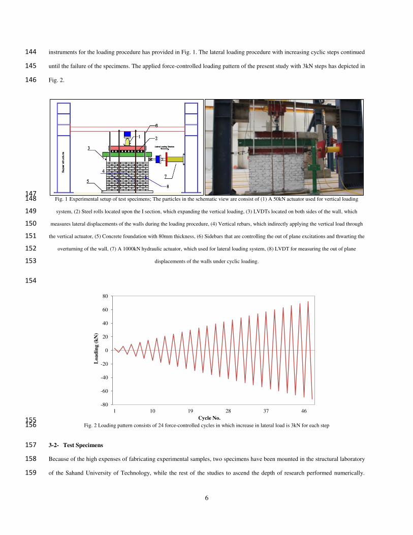
In Fig. 9, the load-displacement curves obtained for the studied specimens and a comparison with experimental results have been 353
presented. The difference between the final strength of experimental and numerical models for specimens 1 and 2 are 18.2% and 354
13.1%, respectively. The difference between the initial stiffness of the studied specimens is 7.5% for specimen1 and 7.7% for 355
specimen2. The analogy of experimental and numerical specimens provides a proper convergence for the extracted results. At the 356
final stage, the cracks of specimen 1 (unretrofitted masonry) were formed with a smaller width, while due to the use of GFRP 357
strips in Specimen 2 (retrofitted masonry), a wide diagonal crack was observed. The GFRP strips were reclaiming the retrofitted 358
wall as an integrated homogeneous object like a shear wall. This proposed method of retrofitting changed the shear-sliding 359
18
failure mode to the sliding failure mode (Fig. 10). According to these outcomes, in the retrofitted specimen, the wall is entirely 360
involved in load-bearing, and this is due to the increase in the integrity of the wall. In this regard, the amount of plastic strain, 361
which is an indicator of partial or thorough damage, is considerably decreased. The stress status of numerically evaluated 362
specimens after applying the vertical loads and at the final stage has shown in Fig. 11. 363
364
Fig. 9 Comparison of load- displacement curve of the experimentally studied specimens with numerical outcomes 365
366
0
10
20
30
40
50
60
70
80
90
0 5 10 15 20 25 30
Late
ral
load
(k
N)
Horizontal displacements (mm)
Specimens 1 (Unretrofitted Wall)
Experimental
Poly. (Numerical )
0
10
20
30
40
50
60
70
80
90
0 5 10 15 20 25 30
Late
ral
load
(k
N)
Horizontal displacement (mm)
Specimens 2 (Retrofitted Wall)
Experimental
Poly. (Numerical)
Specimen 1
Max Plastic Strain

19
367
Fig. 10 Approximate crack formation places in analytical model for Specimen 1 and Specimen 2 368
369
370
Fig. 11 Numerically evaluated specimens before and after application of cyclic horizontal loads. 371
According to the provided counters in Fig. 12, the strain value declined from 0.054% in specimen 1 to 0.028% in specimen 2. In 372
this regard, the strain value in the retrofitted specimen halved, and in exchange, expanded to the entire wall. This homogenous 373
expansion of the strain in specimen 2 leads to ductile rocking failure presented in the experimental study. The outcomes of the 374
numerical analysis for specimen 1, are also covering the extracted results from the empirical research study, the observed failure 375
of which in the unretrofitted wall occurred in brittle diagonal cracking failure. 376
According to numerical outcomes, using GFRP strips in one-third of masonry layers satisfy the expected behavior of the 377
structure. Further numerical analyzes by reducing the number of layers is an endeavor to evaluate whether lesser GFRP strips 378
may satisfy the anticipated behavior of the augmented masonry or the retrofitting procedure become inert. Since both the 379
Specimen 2
Specimen 1
Specimen 2
Gravity + Cyclic Loads
Gravity + Cyclic Loads Gravity Loads
Gravity Loads
Max Plastic Strain
Max Stress
Max Stress

20
numerical and experimental outcomes in both of the specimens have an appropriate convergence, it is expectable that the 380
retrofitting results of the masonries with lesser GFRP strips, the number of retrofitting layers of which reside between the initial 381
specimens, could have acceptable accuracy. 382
4-3- The Effects of Number of Layers 383
To find the optimum reinforcement for the unretrofitted specimen by using the proposed retrofitting technique, the effect of 5 384
retrofitting arrangement for 3, 4, 5, 7, and 14 GFRP layers with 1 mm thickness on the initially evaluated wall in addition to the 385
bare wall examined and results have compared. The increase in stiffness and strength by comparing the results with the 386
unretrofitted specimen assessed. The arrangement of GFRP rows presented in Fig. 12. The ratio of the used GFRP strips to the 387
wall area according to the width and the thickness of the used GFRP strip, the ultimate strength, and the strength increase ratio 388
by comparing them to the unretrofitted specimen have presented in Table 6. By inserting 3 layers of GFRP strips in horizontal 389
bed joints due to the small ratio of AGFRP/wall, the space between the rows of the GFRP layers does not affect the strength 390
considerably, while the further increase of GFRP strips leads to a change in the strength increase rate from 4.5% to 12.1% (Table 391
6). By increasing the number of GFRP layers up to 14 layers, the strength of the wall was increased by 45.9%. Placing GFRP 392
strips in all of the horizontal bed joints from executive and economic viewpoints is problematic. Hence, considering the financial 393
issues, the optimum layers to insert GFRP strips are ranged from 4 to 7 rows in horizontal bed joints. The stress status of further 394
evaluated numerical specimens after applying the vertical loads and at the final stage is shown in Fig. 13. The load-displacement 395
curve of numerically evaluated samples has presented in Fig. 14. 396
397
398
399
400
1 2 3
4 5 6

21
Fig. 12 The schematic view of the bare model and application procedure of GFRP strips in expanding numerical studies. GFRP strips considered 401
to apply in 3 to 14 layers of initially evaluated models to consider the lateral behavior of each model and introduction of the most proper 402
retrofitting model 403
404
405
406
407
Gravity + Cyclic Loads Gravity Loads
Gravity + Cyclic Loads Gravity Loads
Gravity + Cyclic Loads Gravity Loads
Gravity + Cyclic Loads Gravity Loads
3 GFRP
Layers
4 GFRP
Layers
5 GFRP
Layers
7 GFRP
Layers
Max Plastic strain
Max Plastic strain
Max Plastic strain
Max Plastic strain
Max Stress
Max Stress
Max Stress
Max Stress

22
408
Fig. 13 The stress status of the numerically excavated specimens with different GFRP layers after application of gravity loads and at the final 409
stage of loading 410
Table 6 Used FRP percentages for retrofitting of Specimen 1 (Unretrofitted Specimen) 411
Model
Number
Number of GFRP
Row
GFRP
Thickness
(mm)
(AFRP/Awall) %
Ultimate strength
(kN)
Increase rate
(%)
1 0 0 0 56.11 0
2 3 0.96 0.03 58.66 4.5
3 4 0.96 0.04 62.85 12.1
4 5 0.96 0.05 67.33 19.9
5 7 0.96 0.07 70.62 25.8
6 14 0.96 0.14 81.89 45.9
412
Fig. 14 Load -displacement curve of the studied numerical samples 413
0
10
20
30
40
50
60
70
80
90
0 10 20 30
La
tera
l lo
ad
(k
N)
Horizontal displacements (mm)
14 row FRP
7 row FRP
5 row FRP
4 row FRP
3 row FRP
0
5
10
15
20
25
30
35
40
45
50
14GFRP
rows
7GFRP
rows
5GFRP
rows
4GFRP
rows
3GFRP
rows
Reference
specimen
Incr
ease
in
str
eng
th a
ccord
ing
to
bare
mod
el(%
)Gravity + Cyclic Loads Gravity Loads
14 GFRP
Layers
Max Plastic strain
Max Stress

23
5- Conclusion 414
This study aimed to provide a method of retrofitting masonry walls, which barely affects the façade of the building in a manner 415
that increases the ductility content of the complex. While one of the main problems of masonries is their brittle behavior, an 416
increase in ductility could considerably improve their lateral behavior. According to the experimental and numerical experiences 417
of this study, the following results were extracted. 418
The proposed retrofitting method leads to a gradual failure of the wall. Hence, the integrity of the wall, even after 419
failure retained. The first crack in the wall took place in the high lateral load values. Due to their high elasticity 420
modulus and correspondingly stiffness content, FRP strips inaugurate to absorb a considerable amount of the lateral 421
load when the cracks were created. 422
Reinforcement of the wall by utilizing the proposed method increases the shear capacity, load-bearing capacity, initial 423
stiffness, and in-plane strength. Although the intended retrofitting method increased both stiffness and ductility 424
parameters, augmentation in ductility was more than stiffness. Since this method of retrofitting does not increase the 425
mass of the structure, which directly leads to the absorbing of further seismic loads, the load-bearing capacity by the 426
increase in the ductility content shall enhance. 427
GFRP strips change the brittle failure to a soft failure mode. In the first experimentally studied specimen, the lateral 428
load undertook with the shear strength of the mortar. Since the mortar had low shear strength, the wall collapsed in 429
mixed diagonal crack and bed joint sliding failure mode. The second specimen has the horizontal GFRP strips, which 430
bear the lateral forces in cooperation with the mortar shear strength. The wall loses strength from weaker row with bed 431
joint sliding mode, failure of which was more ductile than the first studied experimental specimen. 432
Ultimate strength, maximum displacement, and absorbed energy of the retrofitted walls with 14 rows of GFRP layers 433
are 23.1, 2.08, and 2.5 times larger than the first experimentally studied wall, respectively. The high maximum 434
displacement of the retrofitted wall indicates that the wall has a higher plastic content which could be a notification for 435
collapse. The outcomes for samples with 3, 4, 5, and 7 GFRP layers are almost close, while the difference with the 14 436
GFRP layers is tangible. 437
According to the results, a retrofitted wall converts cracks with a greater depth to small cracks with less thickness. 438
GFRP strip makes all parts of the wall act as an integrated object and resists the lateral load. The experimental 439
observations, which were also proved by numerical studies, demonstrate that the strain distribution in retrofitted 440
specimens is more homogenous, leads to the formation of lesser plastic strain points in the specimens, and increases 441
the load-bearing capacity and prosperity of the retrofitted specimens. 442

24
6- Data Availability 443
Since some outcomes of this study didn't publish in any other Journal, all data, models, and the results that support the findings of 444
this study are available from the corresponding author upon reasonable request. 445
References 446
447
36 CFR 68, the Secretary of the Interior's Standards for the Treatment of Historic Properties (2012), Code of Federal Regulations, 448
16 U.S.C. 470et seq. 449
Abdulla, K.F., Cunningham, L.S. and Gillie, M. (2017), “Simulating masonry wall behaviour using a simplified micro-model 450
approach”, Engineering Structures, 151, pp. 349–365. 451
Aghabeigi, P., Mahmoudi, R., Ahani, E., & Hosseinian Ahangarnazhad, B. (2020). Seismic Assessment and Retrofitting of the 452
Masonry Building of Mozaffarieh Timche in Tabriz Historic Bazaar. International Journal of Architectural Heritage, 1-26. 453
Ahani, E., Mousavi, M.N., Rafezy, B. and Osmanzadeh, F. (2019), “Effects of Central Opening in Masonry Infill on Lateral 454
Behavior of Intermediate RC Frames”, Advances in Civil Engineering Materials, 8, 1, pp. 23–42. 455
American Concrete Institute, committee 369 (2011). Guide for seismic rehabilitation of existing concrete frame buildings and 456
commentary. 457
American Concrete Institute, committee 440 (2008). Guide for the Design and Construction of Externally Bonded FRP Systems 458
for Strengthening Concrete Structures. 459
American Concrete Institute, committee 562 (2013). Code requirements for evaluation, repair, and rehabilitation of concrete 460
buildings and commentary. 461
American Society of Civil Engineers. (2007). Seismic Rehabilitation of Existing Buildings (ASCE/SEI 41-06), American Society 462
of Civil Engineers. 463
Anagnostopoulos, S., Moretti, M., Panoutsopoulou, M., Panagiotopoulou, D., & Thoma, T. (2004). Post-earthquake damage and 464
usability assessment of buildings: further development and applications. Final report. 465
Applied Technology Council, The Partnership for Response and Recovery, & Federal Emergency Management Agency. (1998). 466
Repair of earthquake damaged concrete and masonry wall buildings (FEMA 308). Washington DC. 467
Arslan, M.E., Celebi, E (2019), “An experimental study on cyclic behavior of aerated concrete block masonry walls retrofitted 468
with different methods” Construction and Building Materials, 200,pp.226–239. 469
ASCE/Structural Engineering Institute. (2003). Seismic Evaluation of Existing Buildings (ASCE/SEI 31-03), American Society 470
of Civil Engineers. 471
ASTM C67-11, Standard Test Methods for Sampling and Testing Brick and Structural Clay Tile, ASTM International, West 472
Conshohocken, PA, 2011, www.astm.org. 473

25
ASTM C109/C109M-11, Standard Test Method for Compressive Strength of Hydraulic Cement Mortars (Using 2-in. or [50-mm] 474
Cube Specimens), ASTM International, West Conshohocken, PA, 2011, www.astm.org. 475
ASTM C348-08, Standard Test Method for Flexural Strength of Hydraulic-Cement Mortars, ASTM International, West 476
Conshohocken, PA, 2008, www.astm.org. 477
ASTM E518/E518M-15, Standard Test Methods for Flexural Bond Strength of Masonry, ASTM International, West 478
Conshohocken, PA, 2015, www.astm.org. 479
ASTM G115-04, Standard Guide for Measuring and Reporting Friction Coefficients, ASTM International, West Conshohocken, 480
PA, 2004, www.astm.org. 481
ASTM C469/C469M-14, Standard Test Method for Static Modulus of Elasticity and Poisson’s Ratio of Concrete in 482
Compression, ASTM International, West Conshohocken, PA, 2014, www.astm.org, DOI: 10.1520/C0469_C0469M-14. 483
ASTM C1314-18, Standard Test Method for Compressive Strength of Masonry Prisms, ASTM International, West 484
Conshohocken, PA, 2018, www.astm.org, DOI: 10.1520/C1314-18. 485
ATC-40, Volume 1, (1996), Seismic Evaluation and Retrofit of Concrete Buildings, Seismic Safety Commission, California, p. 486
346. 487
BHRC (2005). Iranian code of practice for seismic resistance design of buildings, Standard 2800-05, 3rd Edition, BHRC 488
Publication No. S-253, Building & Housing Research Center, Tehran, Iran. 489
Borri, A., Casadei, P., Castori, G., & Hammond, J. (2009). Strengthening of brick masonry arches with externally bonded steel 490
reinforced composites. Journal of composites for construction, 13(6), 468-475. 491
Bostenaru-Dan, M., Penelis, G. G., & Bourlotos, G. (2013). RETROFIT OF STONE MASONRY BUILDINGS IN GREECE: I. 492
DAMAGE PATTERNS AND PREVENTIVE RETROFIT/REPAIR MEASURES. Buletinul Institutului Politehnic din lasi. 493
Sectia Constructii, Arhitectura, 59(2), 19. 494
Burgoyne, C. (2009, July). Fibre reinforced polymers–strengths, weaknesses, opportunities and threats. In Proceedings of the 9th 495
international symposium on fiber reinforced polymer reinforcement for concrete structures (FRPRCS-9), Sydney, Australia (pp. 496
13-15). 497
Canadian Standards Association. (2006). Canadian highway bridge design code (CHBCD), CAN/CSA-S6-06. Toronto, Ontario, 498
Canada. 499
Canadian Standards Association. (2012). Design and construction of building structure with fibre-reinforced polymer, CAN/CSA 500
S806-12, Toronto, Ontario, Canada. 501
Calvi, G. M., Bolognini, D., & Penna, A. (2004). Seismic performance of masonry-infilled RC frames: benefits of slight 502
reinforcements. Invited lecture to “Sísmica, 6, 14-16. 503
Capozucca, R. (2010), “Experimental FRP/SRP–historic masonry delamination”, Composite Structures, 92, pp. 891–903. 504

26
Capozucca, R. (2011), “Experimental analysis of historic masonry walls reinforced by CFRP under in-plane cyclic loading”, 505
Composite Structures, 94, pp. 277–289. 506
Cannizzaro, F., Pantò, B., Lepidi, M., Caddemi, S., & Caliò, I. (2017). Multi-directional seismic assessment of historical masonry 507
buildings by means of macro-element modelling: Application to a building damaged during the L’Aquila earthquake (Italy). 508
Buildings, 7(4), 106. 509
Chaimoon, K. and Attard M.M. (2007), “Modeling of unreinforced masonry walls under shear and compression”, Engineering 510
Structures, 29 , pp. 2056–2068. 511
Corradi, M., Castori, G., Sisti, R., Borri, A., & Pesce, G. L. (2019). Repair of Block Masonry Panels with CFRP Sheets. 512
Materials, 12(15), 2363. 513
Council, B.S.S. (1992). NEHRP Handbook of techniques for the seismic rehabilitation of existing buildings (FEMA 172). 514
Washington DC. 515
D’Ayala, D.F. (2013). Assessing the seismic vulnerability of masonry buildings. In Handbook of seismic risk analysis and 516
management of civil infrastructure systems (pp. 334-365). Woodhead publishing. 517
D’Ayala, D.F., & Paganoni, S. (2011). Assessment and analysis of damage in L’Aquila historic city centre after 6th April 2009. 518
Bulletin of Earthquake Engineering, 9(1), 81-104. 519
Dadras Eslamlou, S., Masia, M.J., Totoev, Y.Z., & Page, A.W. (2019). Effect of retrofitting on the structural factors for seismic 520
assessment of unreinforced masonry structures: a review. Australian Journal of Structural Engineering, 20(1), 26-53. 521
Developing Successful Risk Reduction Programs, Federal Emergency Management Agency, & Applied Technology Council 522
(2009), Unreinforced masonry buildings and earthquakes (FEMA P-774). Washington DC. 523
Dhanasekar, M. and Haider, W. (2008), “Explicit finite element analysis of lightly reinforced masonry shear walls”, Computers 524
and Structures, 86, pp. 15–26. 525
Dizhur, D., Ingham, J., Moon, L., Griffith, M., Schultz, A., Senaldi, I., , Magenes, G., Dickie, J., Lissel, S., Centeno, J. and 526
Ventura, C. (2011). Performance of masonry buildings and churches in the 22 February 2011 Christchurch earthquake. 527
Dolatshahi, K.M. and Aref, A.J. (2011), “Two-dimensional computational framework of meso-scale rigid and line interface 528
elements for masonry structures”, Engineering Structures, 33, , pp. 3657–3667. 529
Doran, B., Yuzer, N., Aktan, S., Oktay, D., & Ulukaya, S. (2019). Numerical Modeling of Traditional Masonry Walls 530
Strengthened with Grout Injection. International Journal of Architectural Heritage, 1-16. 531
ElGawady, M.A., Lestuzzi, P. and Badoux, M. (2004), “A review of conventional seismic retrofitting techniques for URM”, 13th 532
international brick/block masonry conference, Amsterdam, 4-7 July. 533
Eurocode, C. E. N. (2004). 8: Design of structures for earthquake resistance—Part 1: General rules, seismic actions and rules for 534
buildings, EN 1998-1. European Committee for Normalization, Brussels. 535

27
Eurocode, C. E. N. (2005). 8: Design of structures for earthquake resistance-Part 3: Assessment and retrofitting of buildings, EN 536
1998–3. European Committee for Standardization: Bruxelles, Belgium. 537
Fabbrocino, F., Vaiano, G., Formisano, A., & D'AMATO, M. (2019). Large scale seismic vulnerability and risk of masonry 538
churches in seismic prone areas: two territorial case studies. Frontiers in built environment, 5, 102. 539
Federation Internationale du Béton (FIB). (2001). Externally Bonded Reinforcement of RC Structures: Basis of design and safety 540
concept, fib Task Group 9.3, fib Bullettin 14. International federation for structural concrete, Lausanne, Switzerland. 541
Federation Internationale du Béton (FIB). (2003). Seismic assessment and retrofit of reinforced concrete buildings. fib Task 542
Group 7.1, fib Bullettin 24. International federation for structural concrete, Lausanne, Switzerland. 543
FEMA 440, (2005), Improvement of Nonlinear Static Seismic Analysis Procedures. Applied Technology Council (ATC-55 544
Project), California. 545
Ferreira, T.M., Mendes, N., & Silva, R. (2019). Multiscale Seismic Vulnerability Assessment and Retrofit of Existing Masonry 546
Buildings. Buildings, 9(4), 91. 547
Gattulli, V., Lofrano, E., Paolone, A. and Pirolli, G. (2017), “Performances of FRP reinforcements on masonry buildings 548
evaluated by fragility curves”, Computers and Structures, 190, pp. 150–161. 549
Gerns, E.A. and Wegener, T.R. (2003), “Repointing Historic Masonry Structures” ASTM standardization news : SN; 31, 8, ISSN: 550
0090-1210, 1094-4656. 551
Grande, E., Imbimbo, M. and Sacco, E. (2013), “Finite element analysis of masonry panels strengthened with FRPs”, 552
Composites: Part B, 45, pp. 1296–1309. 553
Issue No. 376, (2007), Iranian Guideline for Seismic Rehabilitation of Existing Masonry Buildings, Tehran, Iran. 554
Haach, V.G., Vasconcelos, G. and Lourenço, P.B. (2010), “Experimentally analysis of reinforced concrete block masonry walls 555
subjected to in-plane cyclic loading”, J Struct Eng, 136(4), pp. 452–462. 556
Kalali, A. and Kabir, M.Z. (2012a), “Cyclic behavior of perforated masonry walls strengthened with glass fiber reinforced 557
polymers”, Scientia Iranica, 19 (2), pp. 151–165. 558
Kalali, A. and Kabir, M.Z. (2012b), “Experimental response of double-wythe masonry panels strengthened with glass fiber 559
reinforced polymers subjected to diagonal compression tests”, Engineering Structures, 39, pp. 24–37. 560
Kmiecik, P. and Kaminski, M. (2011), “Modeling of reinforced concrete structures and composite structures with concrete 561
strength degradation taken into consideration”, Archives of Civil and Mechanical Engineering, 11(3), pp. 623-636. 562
Knox, C.L., Dizhur, D. and Ingham, J.M. (2018), “Experimental study on scale effects in clay brick masonry prisms and wall 563
panels investigating compression and shear related properties”, Construction and Building Materials, 163, pp.706–713. 564

28
Konthesingha, K.M.C., Masia, M.J., Petersen, R.B., Mojsilovic, N., Simundic, G. and Page, A.W. (2013), “Static cyclic in-plane 565
shear response of damaged masonry walls retrofitted with NSM FRP strips – An experimental evaluation”, Engineering 566
Structures, 50, pp. 126–136. 567
Lin, Y., Lawley, D., Wotherspoon, L., & Ingham, J. M. (2016, August). Out-of-plane testing of unreinforced masonry walls 568
strengthened using ECC shotcrete. In Structures (Vol. 7, pp. 33-42). Elsevier. 569
Lourenço, P.B. (1994) “Analysis of masonry structures with interface elements: Theory and applications”, Report 03-21-22-0-01, 570
Delft University of Technology, Delft, Netherlands. 571
Lourenco, P.B. (1996), Computational strategies for masonry, Delft University Press, The Netherlands, ISBN 90-407-1221-2. 572
Luccioni, B. and Rougier V.C. (2011), “In-plane retrofitting of masonry panels with fibre reinforced composite materials” 573
Construction and Building Materials, 25, pp. 1772–1788. 574
Magenes, G. and Calvi, G.M. (1997), “In-plane seismic response of brick masonry walls”, Earthquake Eng Struct Dyn, 26(11), 575
pp. 1091–1112. 576
Marcari, G., Manfredi, G., Prota, A. and Pecce, M. (2007), “In-plane shear performance of masonry panels strengthened with 577
FRP”, Composites: Part B, 38, pp. 887–901. 578
Marcari, G., Oliveira, D.V., Fabbrocino G. and Lourenco, P.B. (2013), “Shear capacity assessment of tuff panels strengthened 579
with FRP diagonal layout”, Composites: Part B, 42, pp. 1956–1965. 580
Masonry Standards Joint Committee. (2011). Building code requirements for masonry structures (TMS 402-11/ACI 530-581
11/ASCE 5-11). The Masonry Society, Boulder, CO. 582
McGuire, W., & Leyendecker, E. V. (1974). Analysis of Non-Reinforced Masonry Building Response to Abnormal Loading and 583
Resistance to Progressive Collapse. US Department of Commerce, National Bureau of Standards. 584
Milani, G., Shehu, R. and Valente, M. (2017), “Seismic Vulnerability Reduction of Masonry Churches: A case study”, Procedia 585
Engineering, 199, pp. 272–277. 586
National Association of Home Builders (NAHB) Research Center. (1994). Assessment of damage to residential buildings caused 587
by the Northridge earthquake. 588
National Sciety for Earthquake Technology-Nepal (NSET). (2009), Seismic Vulnerability Evaluation Guideline for private and 589
public buildings. 590
NZSEE. (2017). The Seismic Assessment of Existing Buildings: Technical Guidelines for Engineering Assessments. Part C-591
Detailed Seismic Assessment. Part C8-Unreinforced Masonry Buildings. 592
Papayianni I. (2015) Retrofitting and Strengthening Masonries of Heritage Structures: Materials Used. In: Beer M., 593
Kougioumtzoglou I.A., Patelli E., Au SK. (eds) Encyclopedia of Earthquake Engineering. Springer, Berlin, Heidelberg. 594

29
Paret, T.F., Searer, G.R. & Freeman S.A. (2019), The Seismic Strengthening of Temple Sherith Israel, STRUCTURE magazine, 595
May. 596
Prakash, S.S. and Alagusundaramoorthy. P. (2008), “Load resistance of masonry wallettes and shear triplets retrofitted with 597
GFRP composites”, Cement & Concrete Composites, 30, pp.745–761. 598
Reboul, N., Mesticou, Z., Si Larbi, A. and Ferrier, E. (2018), “Experimental study of the in-plane cyclic behaviour of masonry 599
walls strengthened by composite materials”, Construction and Building Materials, 164, pp. 70–83. 600
Sandoval, C. and Roca, P. (2012), “Study of the influence of different parameters on the buckling behavior of masonry walls”, 601
Construction and Building Materials, 35, pp. 888–899. 602
Santa-Maria, H. and Alcaino, P. (2011), “Repair of in-plane shear damaged masonry walls with external FRP”, Construction and 603
Building Materials, 25, pp. 1172–1180. 604
Sarker, P., Begum, M., & Nasrin, S. (2011). Fiber reinforced polymers for structural retrofitting: A review. J Civil Eng, 39(1), 605
49-57. 606
Secretary of the Interior. (1995) Standards for the Treatment of Historic Properties: With Guidelines for Preserving, 607
Rehabilitating, Restoring & Reconstructing Historic Buildings, National Park Service, Washington D.C. 608
Senthivel, R. and Lourenço, P.B. (2009), “Finite element modelling of deformation characteristics of historical stone masonry 609
shear walls”, Engineering Structures, 31, pp. 1930-1943. 610
Shabdin, M., Attari, N.K., & Zargaran, M. (2018). Experimental study on seismic behavior of Un-Reinforced Masonry (URM) 611
brick walls strengthened with shotcrete. Bulletin of Earthquake Engineering, 16(9), 3931-3956. 612
Tasnimi, A.A., & Rezazadeh, M.A. (2012). Experimental and numerical study of strengthened single storey brick building under 613
torsional moment. International Journal of Civil Engineering, 10(3), 232-244. 614
Tomaževič, M. (1999), “Earthquake-resistant Design of Masonry Buildings”, Imperial College Press, Volume 1 of Series on 615
innovation in structures and construction, ISBN 1860940668, 9781860940668. 616
Valente, M., Barbieri, G. and Biolzi, L. (2017), “Seismic assessment of two masonry Baroque churches damaged by the 2012 617
Emilia earthquake”, Engineering Failure Analysis, 79, pp.773–802. 618
Wang, C., Forth, J.P., Nikitas, N. and Sarhosis, V. (2016), “Retrofitting of masonry walls by using a mortar joint technique; 619
experiments and numerical validation”, Engineering Structures, 117, pp. 58–70. 620
Wang, X., Ghiassi, B., Oliveira D.V. and Lam C.C. (2017), “Modeling the nonlinear behaviour of masonry walls strengthened 621
with textile reinforced mortars”, Engineering Structures, 134, pp.11–24. 622


![Retrofit Historical Masonry Walls with GFRP under Seismic Loading · 2015. 6. 11. · historic masonry building in seismic areas [7,8]. In the study of Catherin et al .[9] , an application](https://img.dokumen.tips/doc/110x75/6116ea99965243058f072b2d/retrofit-historical-masonry-walls-with-gfrp-under-seismic-loading-2015-6-11.jpg)