Embed Size (px)
Citation preview

AD-R124 335 INTEGRATED NUCLEAR AND CONVENTIONAL THEATER MARFARE in-SIMULATION (INUARS) D. CU) BDM CORP MCLEAN VA
JALDRICH ET AL. 89 FEB 89 9DM/N-Ba 947-TR-PT-4-2
UCASIFIED DRG39-77-C-gi74 F/G 15/7 , NIENhELhhhiEohhshhEElhhEE
EhhhE~~hFENDEhhhh~h!hhL

0125m IA M,.VIROMRE 3UTM TETCHR
LL-.

j~k124335 n
THE
m CORPORATION
40
,.soo - vol , ow
lp0
8802 010 017'

p.--.' 2. 7
THE mCORPORATION
7915 Jones Branch DriveMcLean, Virginia 22102Phone (703) 821-5000
February 8, 1980
BDM/W-80-047-TR
INTEGRATED NUCLEAR AND CONVENTIONALTHEATER WARFARE SIMULATION (INWARS)
DOCUMENTATION PART IV
USER'S MANUAL COMPONENT
VOLUME II:
COMBAT INTERACTIONS INPUT
sowfiom

UNCLASSIFIEDSECURITY CLASSIFICATION OF THIS PAGE (f'Wen Dole £nt.,.d)
REPOT DCUMNTATON AGEREAD INSTRUCTIONSREPOT DO MENTTIONPAGEBEFORE COMPLETING FORM0
0 NMUft2. GOVT ACCESSION NO. S. RECIPIENT'S CATALOG NUMBER
4. TITLE (and Subitle) S. TYPE OF REPORT A PERIOD COVERED
Final-Integrated Nuclear and ConventionalTheater Warfare Simulation (INWARS). User's ManualFinal Report-Part IV, Vol ume II S.PERFORMING ORG. REPORT NME
BDM/W-8-047-TR7. AUTNOR(aj 6. CONTRACT ONGRANT NUMUER(s)
Dr. J.R. AldrichJ.B. Gilmer DAAG39-77-C-0174
9. PERFORMING ORGANIZATION NAME AND ADDRESS 10. PROGRAM ELEMENT. PROJECT. TASK
The BD#4 Corpo ration AREA & WORK UNITNUBR
7915 Jones Branch DriveMcLean,_VA 22101 ____________
1I. C 1;."L jj~Fir CE a AND ADDRESS 12. REPORT DATE
fl4I'I~UDI'ILUJFebruary 8. 1980The Pentagon, Room 3A546 13. NUMBER OF PAGES
Washington. D.C. 20310 7044. MONITORING AGENCY NAME 0 ADDRESSj'it different from, Controlling 0111 re) IS. SECURITY CLASS. (of this report)
UnclassifiedAS. DLSSIFICATION/DOWNGRADING
IS.SC.EDULE
IS. DISTRIBUTION STATEMENT lot this. Report)
Unlimited
IT. DISTRIBUTION STATEMENT (of the abstract entered In Block 20. if different from, Repor)
UnlimitedIS. SUPPLEMENTARY NOTES
It. KEY WORDS (Conthiues an ewear.. side Of necessary An Identify by block rnmber)
Theater Simul ationCommand-Control -Intelligence
Combat Interactions
20. ABSTRACT (Continua an wear., side Dlmeceeaw OaId ntgfp by meck niabor t
This manual provides user documentation on the INWARSsimulation.
DN ONPN7 1473 EDITION OF I NOV 4813S OBSOLETE UCASFESECURITY CLASSIFICATION OF THIS PAGE (Whmen Data Entered)

rHE BDMV CORPORATION
FOREWORD
This is Volume II of the User's Manual Component of the Integrated
Nuclear and Conventional Theater Warfare Simulation (INWARS) documentation.
It presents the content and format of user inputs to the INWARS treatment :-
of combat interactions. -
PART I - IRNAS SYNOPSIS
PART II - OIIIN DESCRIPTION
VOL. I INTRODUCTION
VOL. IX GROW COAT OPERATIONS
VOL. III AIR OPERATIONSVOL. IV C(BMAT SUPPORT OPERATIONS-V
VOL. V ECIELON AM DIVISION CUOID, CONTROL, AND"
INTILLIIINCE (EAD C2 1) ACTIVITIES
PART 1I - SOFTM DESCRIPTION
VOL. I SO FROMM,..
VOL. II EAD A DATA STRUCTURESVOL. III CAD CI PROCE S .
VOL. IV INFORMATION COLLECTION MD COINISICATION DATA
STUJCTUKS AN PROCUESVOL. V COMBAT INTERACTIONS DATA STRUCTURESVOL. VI COMAT INTERACTIONS PROCEDURES
PART 1V - USER'S MISNUAL .. ,.
VOL. I INTRODUCTIONS VOL. I I COAT INTERACTIONS INPUTS
VOL. III EAD C21 INPUTSVOL. IV INIARS OUTPUTS £ee,,s.e n For
Slt r ibtt ! on/'-:.£,aI-l,bUlty Codes
bltt SpOeal-
96 I107

E 8BDM CORPORATION
TABLE OF CONTENTS
COMBAT INTERACTIONS INPUT SPECIFICATIONS
Section Page
FOREWORDii
TABLE OF CONTENTS v
LIST OF FIGURES vii
LIST OF TABLES ix
A GENERAL COMMENTS1
B Run Control and Diagnostic Features 4
C Information Degradation Data 7
D Terrain Effects and Search Data 10
E Entity Type Descriptor Data 15 :
F Weapon/Asset Characteristics Data 19
G Nuclear/Chemical Readiness Tables 29
H Operation Reaction System Tables 33
I Operations Data 43
J Contingency Data 57
K Hex Data 58
L Entity Assignment Data 61-
* ..

THE BDM CORPORATION
LIST OF FIGURES
Figure Pg
1 Octal Number Use 3
2 Information Degradation Input Deck 8
3 Search Data Deck 12
4 Entity Type Description Deck 14
5 Asset Data 20
6 Table Nuclear/Chemical Readiness Input Deck 32
7 Operation Reaction System Deck 35
* 8 Operations Data Deck 444
9 Hex Input Deck 60
10 Entity Input Deck 63
4°*
N:
-" vii
.11

THE BDM CORPORATION
,: LIST OF TABLES
Table Page
I Debug Flags 2
2 Data Structures Dump Control Flags 6
1ix
lA:
.9I
*9% I

THE BDM CORPORATION*4
INPUT SPECIFICATIONS
A. GENERAL COMMENTS
This volume specifies the inputs to the Combat Interactions portion of
the INWARS model. This software may be run either in a stand alone mode,or as part of the integrated INWARS model. In the latter case, the run
control cards given in Section A are omitted.The function of the inputs are to initialize various data structures
which define operations weapons, terrain, units, and other aspects of the
model. Thus, the inputs are organized by the data structure initialized.The data structure definitions are given in "INWARS CIS DATA STRUCTURES" in
sections shown by Table 1, for the respective sections of this volume.
Since the inputs are primarily used to load data structures, the
acceptable range for numbers depends on the space, or number of bits,
allocated to the particular field in the data structured definition. Theminimum value for almost all inputs is zero; blank or negative entries will
usually cause catastrophic software failure. Most "factors" in the model
are stored in nine bits, with a maximum input value of 7.99 in floatingpoint formats or 799 (%) in integer formatted fields. Larger values will
, probably cause software errors, except where the data specifications in
this volume say otherwise.
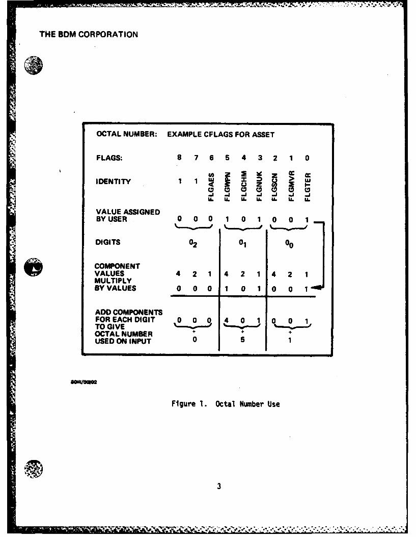
One type of data used throughout the CIS data structures is the"flag." This type of information is normally stored in one bit, and is
used to enable or indicate a particular feature. Examples are flags which
indicate that a weapon is nuclear, or that it is subject to air attack.These flags are put in octal format, with each digit of the octal number
representing three flags, as shown in Figure 1.
When floating point formaL is specified, such as with F5.2, the first
number indicates the total number of card columns used, and the second
*i indicates the number of card columns following the decimal point. Thus,for the F5.2 format, the first two columns would be the integer portion of
the number, the third column a decimal, followed by the fractional value in
the last two columns.'o .. ".

THE 8DM CORPORATION
TABLE 1. DEBUG FLAGS
BIT DECIMAL SUBROUTINE USE
0 1 PERCEV PERCEPTION, ENTRY POINT1 2 PERCEV PERCEPTION, LOOP FOR ALL
PERCEPTIONS2 4 PERCEV PERCEPTION, EXIT POINT3 8 COMBAT COMBAT PROCESS; THIS CAUSES A LOT
OF OUTPUT4 16 CONTNG CONTINGENCY RECOGNIATION PROCESS,
ORS5 32 BGSGO OPERATION REACTION SYSTEM6 64 GETHX GET HEX UTILITY7 128 GETHX2 GET HEX UTILITY, EXIT8 256 GETHX2 GET HEX UTILITY, LOOP (LOTS OF
OUTPUT)9 512 NOT USED
10 1024 NOT USED11 2048 GIMME, ALLOCATION AND RETURN OF DYNAM-
RELEASE ICALLY ALLOCATED MEMORY ARRAYSPACE
12 4096 GUBEOR TRACES ENTRY AND EXIT OF MAJORSUBROUTINES
13 8192 EVALST EVALUATE ENTITY STRENGTH14 16384 DISPOSE DISPOSE OF OLD OPERATION ORDER
DISPOP POP OPORDER STACK15 32768 SITCVT SITUATION CONVERSION OF CODE (ORS)16 65536 GENOBJ GENERATE OBJECTIVE17 131072 NOT USED18 262144 DIVPLN DIVISION PLANNING PROCESS19 524288 DORDER DETAIL TEMPLATE ORDER PROCEDURE20 1048576 HORIEN HEX ORIENTATION UTILITY21 2097152 RECOV RECOVERY FROM SUPPRESSION EFFECTS22 4194304 SCORMV MOVEMENT SECTION, SPEED, AND
PROCESS23 8388608 DAMAGE EQUIPMENT DAMAGE24 16777216 EVALU8 SITUATION FEATURE AGGREGATION25 33554432 RECSGO RECEPTION OF SUPPLY REQUESTS26 67108864 HXMOV MOVEMENT WITHIN HEX TREE27 ABCOPS AIR BASE CLUSTER OPERATIONS28 BDEACT ENTITY OPERATIONS SUPERVISOR29 GSARTY GENERAL SUPPORT ARTILLERY AND
GSARTS SUPPORT REQUEST PROCESSES30 RECARQ RECEPTION OF AIR REQUESTS BY ABC31 CREATE ENTITY CREATION32 PURGEN ENTITY PURSE33 GETTPU GET TEMPLATE RELATION UNIT
UTILITY34 TRANSA TRANSFER ASSETS UTILITY35 EXTSUP EXTERNAL SUPPLY ECHO "
2
. .. . . . . .. . .. . . .... ..j !. . . . .. .. ...- , ... ,
THE BDM CORPORATION
OCTAL NUMBER: EXAMPLE CFLAGS FOR ASSET
FLAGS: 8 7 6 5 4 3 2 1 0
IDENTITY 1 1iW[ x > UCD CD C 9 D C D C
U. U. U. uL U. L U.
VALUE ASSIGNEDBY USER 0 0 0 1 0 1 0 0 1
DIGITS 02 01 00
COMPONENT0S VALUES 4 2 1 4 2 1 4 2 1MULTIPLYBY VALUES 0 0 0 1 0 1 0 0 1
ADD COMPONENTSFOR ACH DIGIT 0 0 0 4 0 1 0 0 1TO GIVE o ,oOCTAL NUMBER + ' +USED ON INPUT 0 5 1
Figure 1. Octal Number Use
3-

, 4
THE BDM CORPORATION
5'
B. RUN CONTROL AND DIAGNOSTIC FEATURES
The cards described here are at the start of each INARS CIS input
deck. They are omitted when the CIS input is used as part of the complete
INWARS model input.
Card 1: Run Control
Inputs: ICON (A4) Input Control:
(columns 10-13) NEWb If new data input
OLOb If old data from ISPACE
Note: Use NEW for input processor, OLD for model
RCON (A4) Run Control:
(columns 14-17) RUNb If run division planning, then
combat model
BDEb To run only the combat model,
no division planning
(Blank) Input only
Note: Use RUN or BDE only for model, not input processor.
CYCLES (15) Specifies the number of combat cycles
(Columns 19-23) for the model
EFLG (A4) Save Flag:
(Columns 25-29) SAVE: At end of run, ISPACE is saved
on device 9
Card 2: Echo Control
Format: 7X, 2A4
Inputs: ECH (A4) Echo Enable
(columns 8-11) YESb If input echo required
bNOb If no input echo desiredOPT (A4) Option Specification
(columns 12-15) ALLb For echo of all inputs
SRCH Search tables
NCRD Nuclear/chemical readiness
data
4
'S.-
,. . . . . .. .
* i6 m W , i-=.. .,-.m l m -, l m . .. , *,,'' W . . . . ..

THE BDIV CORPORATION
.- .:.:.: ORST ORS tables
OPDT Operations data
TABS Includes Search, N/C readi-
ness, ORS, Operations, and
Asset Data
HEXS Hex data
* ENTY Entity dataNotes: 1. This card is omitted if "OLD" is
specified for ICON on Card 1.
2. The option specification allowsrestriction of echo to only part
of the input data.
Card 3: Dump Control
Format: 7X, A4
Input: DCON (A4) Input Diangostic Control
(columns 6-19) YESb Activates diagnostic writes in
GUBEDR, GETHX, GETHX2, GIMMEsubroutines
bNOb No diagnostics on input
Card 5: Model Run Diagnostic Control
Format: 3X, 012 (columns 4-15)
This octal number is a series of 36 flags which selec-
tively enable various debug writes in the CIS software.
Table 1 identifies the bits.
Card 6: Diagnostic Data Structure Dump Control
Format: 3X, 012 (columns 4-15)
This octal number is a series of 36 flags which govern
the operation of the DSDUMP subroutine. This routine
dumps selected data structure at the completion of the
run. Table 2 identifies the bit.
Note: In the input descriptions, the smaller letter b indicates
a blank in the A4 format.
5

THE BDM CORPORATION
* TABLE 2. DATA STRUCTURE DUMP CONTROL FLAGS
BIT DECIMAL USE
0 1 ENTITIES1 2 OPERATION ORDERS (BIT 0 MUST ALSO BE ON)
- 2 4 HEXES AND OCCUPANCY BLOCKS3 8 ASSET DESCRIPTORS
S. 4 16 OPERATION DESCRIPTORS5 32 CONTINGENCY TABLE6 64 SEARCH TABLES7 128 TARGET LIST8 256 OPERATION EFFECTS TABLE (BIT 4 MUST ALSO BE ON)9 512 COMBAT EFFECTS TABLES10 1024 ISPACE DUMP (USES SUBROUTINE FSDUMP)11 2048 ORS TABLES (DOES NOT WORK)12 4096 TYPE DESCRIPTOR BLOCKS13 8192 NUCLEAR/CHEMICAL READINESS TABLES
16384 SUPPLY STRUCTURES (BIT 0 MUST ALSO BE ON)
-.46:'.4'
'o
." , " -." -. -- -', -,4.- ", . . ". .. . . " ' ". . -' - '-. . . . . .... ..".' ". . - - ' -

THE BDM CORPORATION
- -- NOTE - Failure to include the echo control card will cause the program to
abort due to a fatal loader error.
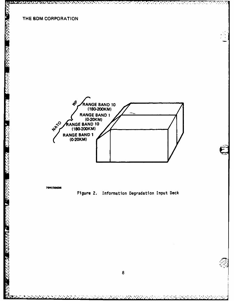
C, INFORMATION DEGRADATION DATA
This data defines the extent to which information collected about
enemy force elements is degraded by loss of qualitative information element
or quantitative precision. Its role is described in the Modeling Descrip-
tion Volume IV, Chapter II. Information degradation is organized by side
(NATO vs Warsaw Pact) and, within side, by 20 milometer "range bands"
around the collecting force element (10 such range bands are permitted).
The Information Degradation Input Deck thus consists of 20 Degradation Data
Sets, one for each side and range band. The organization of the deck is
suggested in Figure 2.
This data is read only in the complete INWARS model version, and
preceeds all other inputs described in this volume. It is not read in the
case of the test version of the combat interactive software. Thus, either
the cards described in Section B or these cards are included depending on
application.
Each Information Degradation Data Set consists of: (1) a set of flags
indicating whether or not associated information element can be collected;
and, (2) a set of measurement unit expressing the precision with which
associated information elements can be collected. Each such data set is
specified on a single card as will now be described.
Format Specification: 811, 12, 313, 16, 213.
Input Variables
DGNATF (I1) = Flag indicating whether or not Nationality
(Column 1) information is degraded (1 = degraded)
DGSVCF (II) = Flag indicating whether or not source informa-
(Column 2) tion (i.e., air versus ground) is degraded
(1 = degraded)
.5 7
THE 6DM CORPORATION
RANGE BAND 10
RANGE BAND 1
APO ANGE BAND 10(180-200KM)
RANGE BAND 1(0-20KM)
7OW/000M
Figure 2. Information Degradation Input Deck
8
THE BDM CORPORATION
S.,
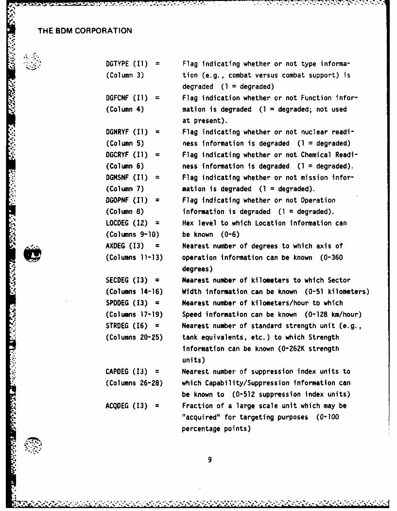
:::."; DGTYPE (I1) = Flag indicating whether or not type informa-
(Column 3) tion (e.g., combat versus combat support) is
degraded (1 = degraded)
DGFCNF (I) = Flag indication whether or not Function infor-
(Column 4) mation is degraded (1 = degraded; not used
at present).
DGNRYF (I1) = Flag indicating whether or not nuclear readi-
(Column 5) ness information is degraded (1 = degraded)
DGCRYF (I1) = Flag indicating whether or not Chemical Readi-
(Column 6) ness information is degraded (1 = degraded).
DGMSNF (Il) = Flag indicating whether or not mission infor-
(Column 7) mation is degraded (1 = degraded).
DGOPNF (II) = Flag indicating whether or not Operation
(Column 8) information is degraded (1 = degraded).
LOCDEG (2) = Hex level to which Location information can
(Columns 9-10) be known (0-6)
AXDEG (3) = Nearest number of degrees to which axis of
(Columns 11-13) operation information can be known (0-360
degrees)
SECDEG (3) = Nearest number of kilometers to which Sector
(Columns 14-16) Width information can be known (0-51 kilometers)
SPDDEG (3) = Nearest number of kilometers/hour to which
(Columns 17-19) Speed information can be known (0-128 km/hour)
STROEG (16) = Nearest number of standard strength unit (e.g.,
(Columns 20-25) tank equivalents, etc.) to which Strength
information can be known (0-262K strength
units)
*;.. CAPDEG (3) = Nearest number of suppression index units to
(Columns 26-28) which Capability/Suppression information can
be known to (0-512 suppression index units)ACQDEG (3) = Fraction of a large scale unit which may be
"acquired" for targeting purposes (0-100
percentage points)
9

THE BDM CORPORATION
0. TERRAIN EFFECTS AND SEARCH DATA
1. Terrain Effects Data
Immediately preceeding the search pattern data are three cards
which allow the user to specify terrain effects on speed, cover, and
obscuration respectively. The first eight values on eac card is for
terrain types zero to seven. The remaining five are for the two types of
artificial barrier hexes, rivers, and the two types of barrier hex sides.
These last five values are omitted on the last card (obscuration).
a. Card 1: Terrain speed effects
FORMAT: 1315 Terrain speed degradation, as a modifi-
TERSPD (I) cation to normal speed for a given oper-
I=1, 13 ation. A value of zero causes no effect,
(columns 1-5,6-10, a maximum value of 64 is used to give com-
11-15, 1620, etc.) plete degradation.
b. Card 2: Terrain cover effects
-'IRMAT: 1315 Terrain cover given as the number of tar-
TERTAB (I) gets of an enemy unit in the hex which
I=1, 13 would result in a 50% probability of tar-
(columns 1-5, 6-10, get acquisition (LOS) to some target for
11-15, 16-20, etc. the average weapon, for each type of ter-
rain. The value for the basic terrain
type in a given hex. This factor is
intended to give the ability of targets
to take advantage of micro terrain cover
in the hex.
c. Card 3: Terrain Obscuration
FORMAT: 815 Terrain obscuration is intended to give
MVALU (I) the effect of limited line of site due to
I=l, 8 macro terrain features such as landform
(columns 1-5, 6-10, and forest. The effect depends on the
11-15, 16-20 disposition of the unit. The value for
,..10
----------.. .... .... .... .... ...

THE BDM CORPORATION
a terrain type is the minimum exponent
to which the disposition is raised to
give the proportion of effective wea-pons. This is applied to direct five
weapons. The maximum exponent is a
reflection of the rage capability of the
weapon. Use zero for artillery and
other indirect fire weapons.
2. Search Patterns:
The data which described the search patterns is organized by
search class and sector width. The initial card gives the number of search
classes. Each class is headed by a card giving the number of search pat-
terns in that class. The actual cards which define the search pattern
follow, headed by a card specifying the number of search vectors in the
pattern and the sector width. The Search Data Deck is illustrated in
Figure 3.
3. Search Deck Header Card
Format Specification: 10X, 15
Input Variable: NSRCHS(15) = Number of search classes
(Columns 11-15)
4. Search Class Header Card
Format Specification: 15
Input Variable: NSRCS(15) = Number of search patterns in class
(Columns 1-5)
5. Search Pattern Header Card
Format Specification: 315
Input Variables:
NHEXES(15) = Number of hex vectors in search
(Columns 1-5)
SECTOR(15) = Sector width for which this search pattern is
(Columns 6-10) defined
11

P THE BDM CORPORATION
8. 3
..
.- ,, $CARDS
SEARCH DATA CARDS
SEARCH PATTERN 7 2HEADER CARD
, SEARCH CLASS r 7CARDS,HEADER CARD
7 VECTORS IN SEARCHSEARCH DECK 2 PATTERN. SECTOR WIDTH = 1HEADER CARD SEARCH 2
2 PATRNS I CLASS
42 SEARCH CLASSES
Figure 3. Search Data Deck
'.1
i 12
•iV -,, -, , - 'f .", ."."." -:f." . . - :'- .''':- '" ' .

7T : 77=
7 Z
THE BDM CORPORATION
* .o, TGTLIM(15) = Number of target units which can be simulta-
(Columns 11-15) neously acquired or engaged by a unit using
this search pattern. If zero, there is no
limit.
6. Search Data Cards
Format Specification: ZX, 03, 315, 4F5.2, 2(4X, 01), 2X, 03
Input Variables:
HSVECT(03) = Search vector (in hex, value > 0)
(Columns 3-5)
HXLEV(15) = Level of search above base level
(Columns 6-10)
RANGE(15) = Range of search from searching unit (zero
(Columns 11-15) for hexes occupied by the unit).
FLNDX(I5) = Flank index indicating side
(COLUMNS 16-20) 1 = left flank
2 = right flank
0 = no flank effects.
COEFl(F5.2) = Threat coefficient for enemy force in hex.
(Columns 21-25) Normal value is one for vector 7.
COEF2(F5.2) = Flank threat coefficient for enemy force
(Columns 26-30) in hex. Normal value is one for vectors
2 or 4.
COEF3(F5.2) = Allocation factor against enemy units in
(Columns 31-35) the hex. Normal value is one for vector 7.
COEF4(F5.2) = Force distribution fraction. All COEF4
(Columns 36-40) factors in the search pattern should sum
to one; COEF4 should be zero if RANGE > 0.
OIRl (01) = Direction for which threat evaluation is
(Column 45) doubled.
0IR2 (01) = Direction for which flank evaluation is
(Column 50) doubled.
ENGFGS(03) = Engagement mode flags: A binary bit is set
13
THE BDM CORPORATION
ENTITY TYPE /. DESCRIPTOR CARDS (/TYPE DATA)
/~ENTY TYPES io"0I- '.o. ~ENTITY TYPE _j\II
HE DE C RD 10 CAR'DS
NUMBER OF ENTITY TYPES I-
80../00o2
,: Figure 4. Entity Type Descriptor Deck
.14
U.
.1w
U..
*444
ENIYTP... DESCRIPTOR. -. CARDS. (TYPE .. .. .DATA), .... . ... •. , ... ...

THE BDM CORPORATION
(Columns 53-55) in this octal field to indicate which engage-
ment modes the searching unit may use to
engage targets in the hex. These flags are:
Bit Engagement Mode
(sb) 0 Counter-Command/Control
1 Indirect Fire
• -2 Direct Fire
3 Anti-Air Defense
*4 Anti-Air
5 Counter Fire
6 Counter Logistics
7-8 Unassigned
7. Notes on Input Data Limits. Effects, and Anomalies
*All input data elements having a floating point format must have
values between 0 and 7.99. Negative numbers or blank entries for any of
the variables will cause errors or model failure during execution. A zero
value should not be used for HSVECT; a value of 7 is used for the "own hex"
search. A value of zero for DIRI or DIR2 will nullify the direction of
movement considerations. A zero for FLNDX causes flank considerations to
be nulled. FLNOX should be less than 3.
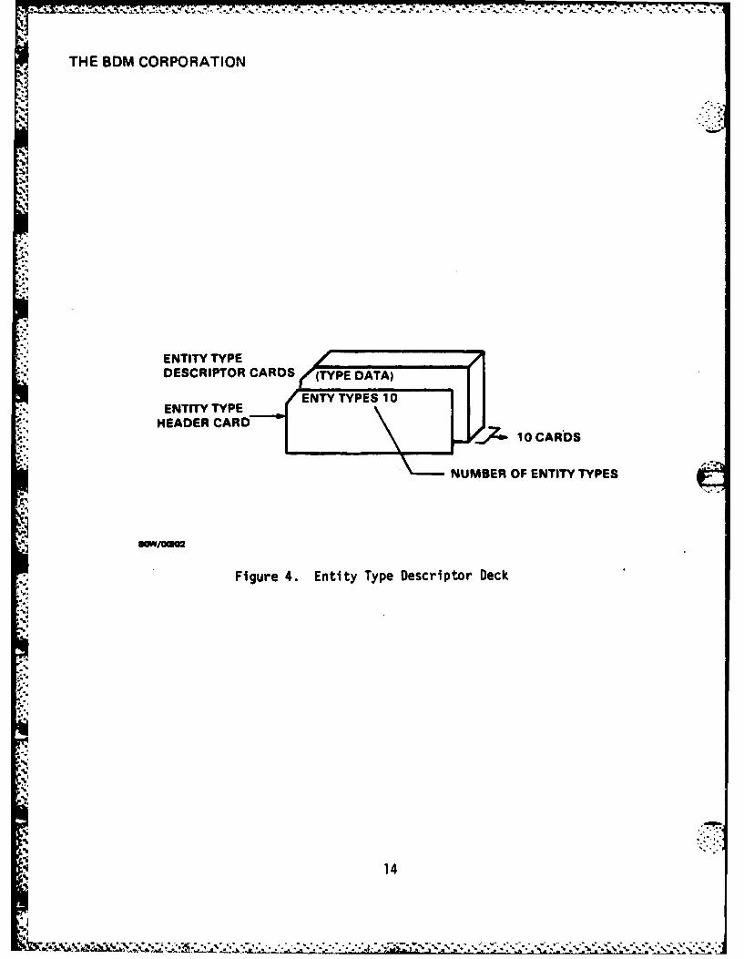
E. ENTITY TYPE DESCRIPTOR DATA
The type descriptor data is commonly used by all entities of a given
type. The types of entities thus distinguished can be given different
operations classes, nuclear readiness posture effects, and different Opera-
tion Reaction System tables. Figure 4 illustrates the makeup of this input
deck.
1. Entity Type Deck Header
Format Specification: lOX, 15
Input Variable: NTYPES(15) = Number of entity types
(Columns 11-15)
11
V *-.... .

THE BDM CORPORATION
2. Type Descriptor Data Cards
Format Specification: 15, 4X, A6, 3X, 02, 1X, 04, 2(2X, 03), 4X,
01, 15
Input Variables:
TYPE(I5) ; Type index (1 to 31)
(Columns 1-5)
NAME(A6) = Alpha description of specified type
(Columns 10-15)
UNICAT(02) = Unit category used in C21 processing.
(Columns 19-20) (Not used by supply).
TFLAGS(04) = Type flags as follows:
(Columns 22-25)
Bit Identity
(lsb) 0-4 - Undefined
5 FLGMVC Move consideration:
0 = normal method
1 = direction to objective only
6 FLGTER Terrain effects. If zero, unit gets
-' no terrain cover benefit during com-
bat processes.
7 FLGSL Shoots last on interim combat during
multi-hex movement
8 FLGSF Shoots first on interim combat during
multi-hex movement
9 Undefined
10 FLGMCB Indicates combat during movement on
hex moves
(msb) 11 FLGMCR Indicate unit receives fire during
multiple hex moves
UNENGR(03) Unit engagement rule flags: A flag is set for
(Columns each engagement made which the entity may
28-30) employ:
5... 16
i%
,.5 - , ' .,, .:.. ; .. .y . .. ::: : . .:, :, : -:::, :.-,-;:: :-:-: -,,-..,.:,-. .:. -.
THE BDM CORPORATION
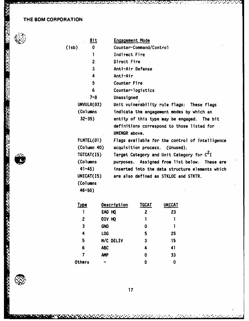
UBit Enaagement Mode
(lsb) 0 Counter-Command/Control
1 Indirect Fire
2 Direct Fire
3 Anti-Air Defense
4 Anti-Air
' 5 Counter Fire
6 Counter-logistics
7-8 Unassigned
UNVULR(03) Unit vulnerability rule flags: These flags
(Columns indicate the engagement modes by which an
32-35) entity of this type may be engaged. The bit
definitions correspond to those listed for
UNENGR above.
FLNTEL(OI) Flags available for the control of intelligence
(Column 40) acquisition process. (Unused).
TGTCAT(I5) Target Category and Unit Category for C2I
(Columns purposes. Assigned from list below. These are
41-45) inserted into the data structure elements which
UNICAT(I5) are also defined as STKLOC and STKTR.
(Columns
46-50)
Type Description TGCAT UNICAT
1 EAD HQ 2 23
2 DIV HQ 1 1
3 GND 0 1
4 LOG 5 255 N/C DELIV 3 15
6 ABC 4 41
7 AMP 0 33
Others - 0 0
17
| ' , i-' : " .......... . ............. .,.... .T.T.-'...;,.'.....,/ "-;.. . "......

THE BDM CORPORATION
STKSUP, STKOPS Stock levels for intelligence acquisition by an
(Columns 61-65, entity of this type. (Value - 0 to 511)
66-70) Not used.
SRCTYP(15) Identifies the type of search/perception pattern
(Columns used by the unit. If it is zero, the search/
71-75) perception pattern is a function of operation.
" NTELEV(15) Indicates the proportion of the perception of
(Columns the situation that depends on subordinate
76-80) unit reports (for division HQ only).
3. Unit Type Limits
These six cards are used to define the type numbers associated
with units which undergo special processing. On each card is a maximum and
minimum type number which will result in recognition as a unit at that
type.
1) Card 1: Echelon Above Division Types:
FORMAT: 215
EADTYP, EADTYH EAD unit types. Both values must be 1.
(columns 1-5, 6-10,
2) Card 2: Division Headquarters types:
FORMAT: 215
TDIVHQ, TDIVHH Division headquarters types. Both
(columns 1-5, 6-10) values must be 2.
3) Card 3: Maneuver Unit types
FORMAT: 215
GNDMV, GNDMVH Ground maneuver unit types. Both values
(columns 1-5, 6-10) normally 3.
4) Card 4: Logistics Unit Types
FORMAT: 215
TLOG, TLOGH Logistics unit types. Both values
(columns 1-5, 6-10) normally 4
5) Card 5: Airbase Cluster Types
FORMAT: 215
18
0*.

* * , = - .. ' Z . . -. - - . .. , - . . . . . .. . .
THE BDM CORPORATION,
TABC, TABCH ABC unit types. Both values normally 6
(columns 1-5, 6-10)
6) Card 6: Nuclear/Ciiemical Delivery Entitles
FORMAT: 215
TNCDE, TNCDEH N/C Delivery Entity types. Both
(columns 1-5, 6-10) normally 5
F. WEAPON/ASSET CHARACTERISTICS DATA - (INTABS)
This data defines the characteristics of all the various assets which
may be attached to entities in the model. This information is stored in
the Asset Descriptor Blocks and associated combat effects tables. Section
3 of "INWARS Combat Interactions Data Structures" provides additional
information.
The Input Deck includes a header card which specifies the number of
different assets which will be defined, the number of target types, and the
resolution to be used for each target type. This is followed by a series
of card sets describing each asset. Figure 5 illustrates.
1. Asset Data Header Card
Format Specification: lOX, 215, 1OF6.2/20X, 1OF6.2Input Variables:
NASSET(15) Number of assets described
(Columns 11-15)
NTGTYP(15) Number of targets types
(Columns 16-20)
TGTRAD(1)(F6.2) Array which gives the resolution used for
(Columns 21-26, each target type. For example, .25 indi-
27-32, 33-38, cates that each 4 integer steps is one
39-44, etc.) individual. Note that there is a limit
on the maximum integer value which can be
put in the asset list. Thus, if the maxi-
mum integer value is 511 (as it is for
2 or 3 assets per asset item structure),
19,.. ..-. ..

THE 6DM CORPORATION
ASSET DESCRIPTOR CARDS (ASSET DESCRIPTOR DATA)
16 SETS OF ASSETDSCRPOCAD
ASSETS DECK .. DERIPHEADER CARD
NUMBER OF SETS OF W-'4 ASSET DESCRIPTOR CARDS
ASSET DESCRIPTOR fALLOCATION DATAI
OPTIONAL. DEPENDING ONTBASIC ASSET DATA
* - Figure 5. Asset Data
20

t
THE BDM CORPORATION
and if a unit may have up to, but no more
than, 127 tanks, then tanks must have a
target class with a value TGTRAD of .25
or greater.
, Note that for NTGTYP - > 10, two cards are used. Provision is made for 20
target types.
2. Asset Descriptor Basic Data
This data is on a series of cards which will be listed separately.
, a. Card I
Format Specification: I5, 4X, A6, 215, 2X, 03, 15, 2(2X, 03), 515
Variable Inputs:
TYPE(I5) Asset type identifier (1 to ASTYPM). The
(Columns 1-5) maximum value allowed depends on the form
of the asset list and is put in as the
variable ASTYPM during compilation. Nor-
mally it will be 511 for INWARS.
Reserved types-
60 = Supply capacity
61 = Repair capacity
59 = Supplies
63 = Air base capacity
NAME(A6) Alpha description of asset.
(Columns 10-15)
* CATEGR(15) This gives the category of which the
(Columns 16-20) asset type is a member. Typical cate-
gories might be for tanks, APC's,
suppliers, etc. This value must be less
than 63. The classes may be assigned as
equal to target type (defined later) as
the simplest alternative.
NXOPS(I5) This operations index specified the class
(Columns 21-25) of operations for which this asset can
act as a weapon. A zero indicates it may
21

THE BDM CORPORATION
act as a weapon regardless of the operation
class of the unit to which it is attached.
NXOPS must be 7 or less, but may be no
greater than the number of classes for
which data is provided.
CFLAGS(03) These flags define certain asset character-
(Columns 28-30) istics as follows:
* Bit Identity Description
0 (lsb) FLGTER Terrain Flag: If 1, indicates that
the weapon is affected by terrain.
I FLGMVR Indicates that combat results are
reduced if a target unit is moving
faster than 1 hex per interval,
reducing engagement time.
2 FLGSCN Indicates target list scan direction.
0 for all except counter-air weapons.•
3 FLGNUK Nuclear weapon
4 FLGCHM Chemical weapon
5 FLGWPN Indicates the asset is a weapon.
6 FLGAES Indicates supply consumption depends
on suppression as well as attrition.
7, 8 Undefined
NTGTS(15) This indicates the number of target types
(Columns 31-35) for which combat parameters are defined.
Values are given for types one to NTGTS,
, even though a weapon may be unable to
engage one of those types. NTGTS must be
no greater than the number of target
classes.
- WPENGR(03) Weapon engagement mode flags. These
(Columns 38-40) indicate the manner in which a weapon may
be used. For a weapon to be used, there
must be a corresponding bit set in its
22
4 . . . . . . . . . . . . . . .

THE BDM CORPORATION
unit, the operation engagement mode flags,
and the vulnerability flags of the target
unit and asset.
. Bit Engagement Mode
0 (lsb) Counter-command/Control
1 Indirect Fire
2 Direct Fire
3 Anti-Air Defense
4 Anti -Ai rcraft
5 Counterfire
6 Anti-Logistics
7, 8 Undefined
WPVULR(03) Asset vulnerability flags. These indicate
. (Columns 42-45) the engagement modes by which the asset
* may be engaged. The flags correspond tothose for WPENGR above.
RANGE(15) Range of the asset in hexes. (Zero for
(Columns 46-50) direct fire weapons in INWARS.)
TGTTYP(15) Target type - Identifies the target class
(Column 51-55) to which this asset belongs.
The target types currently in use are:
(1) Hard targets (tanks)
(2) Medium armor (APCs)
(3) Unarmored or light armor
(4) Artillery
(5) Air defense
(6) Helicopters
(7) Aircraft
(8) Supply and Logistics
(9) Nuclear and Chemical weapons
RNGFAC(15) This value gives a percentage effectiveness
(Columns 56-60) modification which is applied to any engage-
ments at range other than zero. It is
23
S*.'' .. *-. .. . . . . . .

THE BDM CORPORATION
percent with a value of 100 causing no
modification. The maximum value alloweda. is 799.
EFFNDX(15) This effectiveness index gives the relative
(Columns 61-65) contribution of this asset to unit strength
and effectiveness. It must be chosen so
that the total strength of a unit is no
more than the integer value 511. This is
the weighting factor Wi in the strength
evaluation formula:
NASSET
STR = 7 Wi Nii = 1
where STR = unit strength (< 511 limit)
N = integer number of assets of
type i in unit (actual number
of assets divided by the value
in TGTRAD for its target type).
NTABS(15) Number of tables. This value, 0 to 3,
(Columns 66-70) specifies the number of tables associated
with the asset. If zero, then there are
no combat effects tables. If NTABS is 1,
the weapon inflicts attrition only, in
accordance with an attrition table. If
NTABS is 2, a suppression effects table
is also used. If NTABS is 3, then attri-
tion, suppression, and allocation tables
are used.
b. Card 2
Format Specification: 815
Variable Inputs:
MVULN (1-5) Marginal vulnerability of the asset to
24'4 -. .

ETHE BDM CORPORATION
* (Columns 1-5) attrition, compared to others of the same
target class. In percent, with a value
of 100 normal.
SVULN (15) Marginal suppression vulnerability (similar
(Columns 6-10) to MVULN).
NVULN (15) Marginal vulnerability to nuclear weapons
(Columns 11-15) effects.
CVULN (I5) Marginal vulnerability to chemical weapons
(Columns 16-20) effects.
NUCEFF (15) Nuclear readiness effect, indicates the
(Columns 21-25) extent to which the nuclear readiness
posture modifies the effects of enemy
nuclear attack on the asset.
CHMEFF (15) As NUCEFF, but for chemical attack.
(Columns 26-30)
NCEFF (15) Nuclear/Chemical readiness degradation
(Columns 31-35) effect; indicates the extent to which the
weapon's capabilities are degraded by the
readiness state.
SRECOV (IB) Suppression recovery rate; specifies the
(Columns 36-40) amount or percentage of suppression on
the asset which decays away each interval.Note: All of the above are in units of % with a value of 100 "normal"
(except for SRECOV, 100 implies complete recovery). All variables must be
less than 799.
c. Card 3
Format Specification: 615, 3X, 012
Variable Inputs:
TEREFF(15) Terrain effects index. Indicates the
(Columns 1-5) extent to which the asset can take advan-
tage of terrain for cover. Normally 100
(in percent). Maximum value is 799.
TEREFS(15) Target terrain utilization modifier.
25
S . . . . . S- . * .. . .

-.-- -,..,77 .... 77 7 . . .. ' . . . " . . .... ..
THE BDM CORPORATION
(Columns 6-10) This percentage value modifies the target
asset's value of TEREFF. Use 100 for null
modification, zero if the target gets no
terrain benefit. Maximum value is 799.
WPEXP(15) Weapon exponent. The combat effects a
(Columns 11-15) weapon inflicts is proportional to the
number of weapons raised to this power.
It is in lOOths, so that a value of 100 is
the normal "one" exponent. This would be
less than one for certain cases only (such
as nuclear and chemical weapons) whereeffects are very nonlinear.
WPDISF(15) This disposition factor is the extent to
(Columns 16-20) which the disposition of the unit affects
the number of weapons actually able to
fire. The unit disposition is raised to
the WPDISF power to obtain a combat modi-
fication factor. Maximum value is 63. -.
APROP(I5) This specifies the proportion of allocation
(Columns 21-25) of fire which is based on attrition rather
than suppression. It should be between
S0 and 100.
SPEED(I) Maximum speed of the asset in idealized
(Columns 26-30) (or best normal) conditions. In units of
km/hr.
SITUAT(012) This data element is a set of situation
(Columns 34-45) flags which are OR'ed into the situationdescription word of a unit being attacked.
It is primarily used to indicate immediate
victim of a chemical, nuclear, or air
attack for which it is set to 4000, 10000,
or 1000000 octal respectively.
5,' 26
-: . I 5 , J " '4 5I -'V..'... . . . . . .-- ," " " . ..... ." ."" ' "" " " " ' " " ', " '
Z-7 .. -7177.7-7 77-.
THE BDM CORPORATION
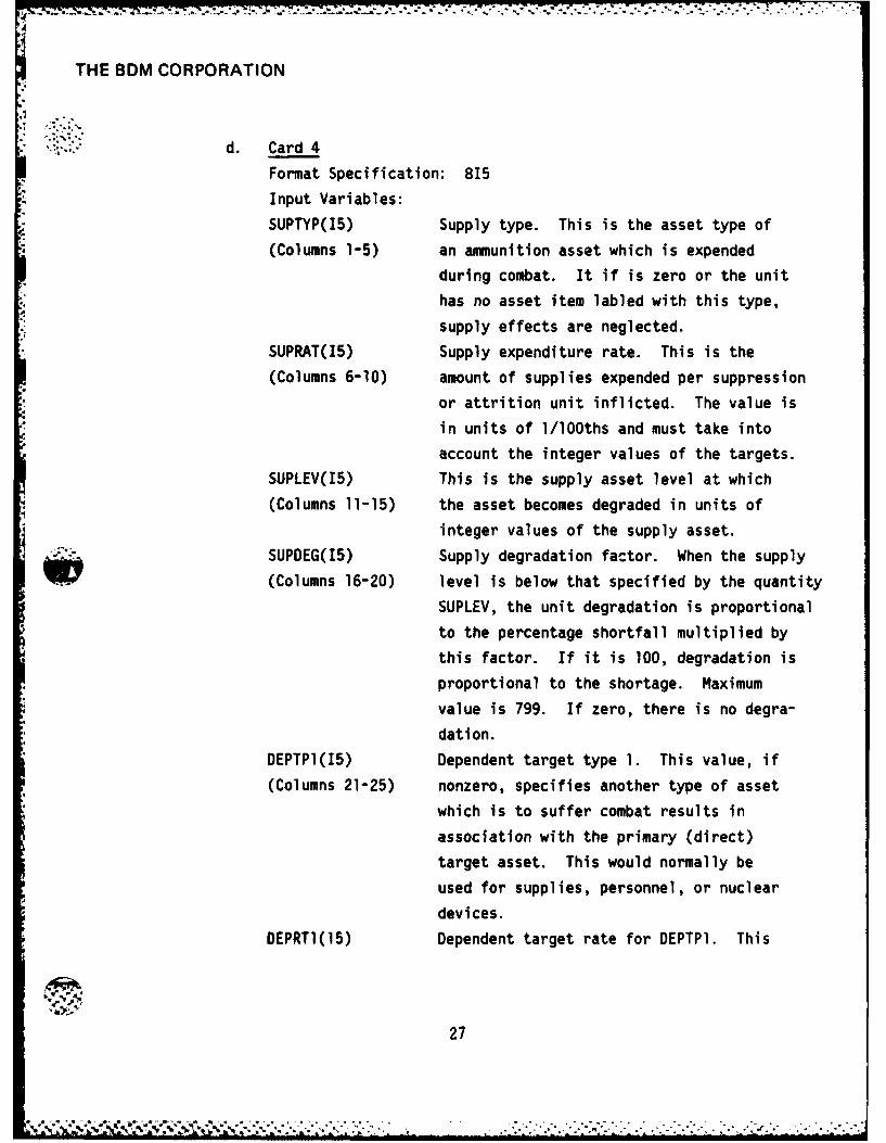
d. Card 4
Format Specification: 815
Input Variables:
SUPTYP(15) Supply type. This is the asset type of
(Columns 1-5) an ammunition asset which is expended
during combat. It if is zero or the unit
has no asset item labled with this type,
supply effects are neglected.
SUPRAT(15) Supply expenditure rate. This is the
(Columns 6-10) amount of supplies expended per suppression
or attrition unit inflicted. The value is
in units of 1/lOOths and must take into
account the integer values of the targets.SUPLEV(15) This is the supply asset level at which
(Columns 11-15) the asset becomes degraded in units of
*integer values of the supply asset.
SUPDEG(I5) Supply degradation factor. When the supply
(Columns 16-20) level is below that specified by the quantity
SUPLEV, the unit degradation is proportional
to the percentage shortfall multiplied by
this factor. If it is 100, degradation is
proportional to the shortage. Maximum
value is 799. If zero, there is no degra-
dation.
DEPTPl(I5) Dependent target type 1. This value, if
(Columns 21-25) nonzero, specifies another type of asset
which is to suffer combat results in
association with the primary (direct)
target asset. This would normally be
used for supplies, personnel, or nuclear
devices.
DEPRTI(15) Dependent target rate for DEPTPI. This
OF 0
27
: , ? . , -.. . . o...........-......... ... :........-...-

THE BDM CORPORATION
(Columns 26-30) value is a scaling factor for combat
results. The attrition and suppression
inflicted on the dependent type are
computed from the combat results on the
primary target asset by multiplying by
this factor. It is given in percent so
that a value of 100 causes equal results.
Maximum value is 799.
DEPTP2(15) Similar to DEPTYP1. Allows a second
(Columns 31-35) dependent target type to be specified.
DEPRT2(15) Dependent target rate for DEPTP2..5
(Columns 36-40)
e. Card 5
Format Specification: 815
Input Variables:
NCTLEV(15) Nuclear/chemical contamination level.
(Columns 1-5) If the weapon is nuclear or chemical,this gives the level of contamination
to be inserted into the terrain.
COLLAT(I5) This value is a multiplier used in com-
(Columns 6-10) puting collateral damage. It is multi-
plied by the population density figure
for the hex attacked.
RADIAT(I5) The application of these variables has
(Columns 11-15) not yet been defined.
CHEMIK(15)
(Columns 16-20)
EXTRAI(15) Tons per unit
(Columns 21-25)
EXTRA2(15) Type of damaged equipment (zero if no
(Columns 26-30) damage)
EXTRA3(15) Type of repaired equipment (zero if no
(Columns 31-35) repair)
28

THE BDM CORPORATION
EXTRA4(I5) Proportion damaged during attrition or
(Columns 36-40) repairable per cyde (depending on which
of EXTRA2 or EXTRA3 is non zero).
3. Allocation Data Cards (Target Tables) (Weapon Effects Tables)
Format Specification: 9F7.2
-3 Input Variables:
VALUE(J)(F7.2) Fire allocation factor for target J up-. (Columns 1-7, to a maximum of J = 9.
8-14, 15-21,
22-28, etc.)
Note: The weapons effects data follows the basic asset descrip-
tor data. It includes up to three tables: attrition, supression, andallocation. The number of tables read is given by NTABS, and the number of
values in each table by NTGTS, both specified on card 1. All tables use a
format as follows: 9F7.2. (If there are more than 9 target types, multiple
cards are read for each table as neccssary.)a. Attrition
The attrition table gives theoretical kill rates against
each of the respective target classes from 1 to NTGTS. This is the number
of kills per time interval. Adjustments for target representation is made
after input by the input processor.
b. Suppression
This table is similar to that of the attrition table, except
the result is supression of the target asset and its unit.
c. Allocation
This table gives allocation factors for the various classesof targets if used.
G. NUCLEAR/CHEMICAL READINESS TABLES
This data defines the impact of Nuclear/Chemical readiness states on
the various model processes. This information is stored in the NCRELM data
structure and is accessed through the TYPLEM and TYPBLK data structures.
29
-- ".....w .... ,.. . ....... ...... ....... . . . . .. ....

THE BDM CORPORATION
Section G of "INWARS Combat Interactions Data Structures" provides addi-
tional information.
The input deck includes a header card which specifies the number of
readiness tables to be input. Each table is specified by an input data set
consisting of three (3) card types. Figure 6 illustrates a two (2) table
nuclear/chemical readiness input deck.
1. Nuclear/Chemical Header Card
Format Specification: lOX, 15
Input Variable:
NNCSTS(15) Number of sets of nuclear/chemical
(Columns 11-15) readiness tables.
2. Applicable Unit Types Card
Format Specification: 815
Input Variables:
NTYP(l)(15) First unit type to which nuclear/chemical
(Columns 1-5) readiness tables apply.
NTYP(2)(15) Second unit type to which nuclear/chemical
readiness tables apply.
NTYP(8)(I5) Last unit type to which nuclear/chemical
(Columns 36-40) readiness tables apply.
Note: Up to eight (8) unit types may be specified for each set
of nuclear/chemical readiness tables. However, as few as one (1) unit type
is sufficient to drive the program without loader errors.
3. Nuclear/Chemical States Card
Format Specification: 215
Input Variables:
NNUCST(15) Number of nuclear readiness states.
(Columns 1-5)
NCHMST(15) Number of chemical readiness states.
(Columns 6-10)
4. Nuclear/Chemical Effects Card
Format Specification: 6F7.3, 3X, 012
30'1.. . . . . . . . . . . . . . . . . . .

THE BDM CORPORATION
Section G of "INWARS Combat Interactions Data Structures" provides addi-
tional information.
The input deck includes a header card which specifies the number of
readiness tables to be input. Each table is specified by an input data set
consisting of three (3) card types. Figure 6 illustrates a two (2) table
nuclear/chemical readiness input deck.
1. Nuclear/Chemical Header Card
Format Specification: lOX, 15
Input Variable:
NNCSTS(15) Number of sets of nuclear/chemical
(Columns 11-15) readiness tables.
2. Applicable Unit Types Card
Format Specification: 815
Input Variables:
NTYP(l)(15) First unit type to which nuclear/chemical
(Columns 1-5) readiness tables apply.
z, NTYP(2)(I5) Second unit type to which nuclear/chemical
readiness tables apply.I NTYP(8)(15) Last unit type to which nuclear/chemical
(Columns 36-40) readiness tables apply.
Note: Up to eight (8) unit types may be specified for each set
of nuclear/chemical readiness tables. -However, as few as one (1) unit type
is sufficient to drive the program without loader errors.
3. Nuclear/Chemical States Card
Format Specification: 215
Input Variables:
NNUCST(15) Number of nuclear readiness states.
(Columns 1-5)
NCHMST(15) Number of chemical readiness states.
*(Columns 6-10)
4. Nuclear/Chemical Effects Card
Format Specification: 6F7.3, 3X, 012
31

THE BDM CORPORATION:.9
2 x 2:4 EFFECT CARDS
4"4
- '!-i:
22 -CRD
NUCLEAR /CHEMICAL SECOND NUC/CHEMEFFECTS CARDS READINESS TABLE
NUCLEAR/CHEMICAL 91. .01.01.01.0 1.0 000000
STATES CARD U -APPLICABLE UI....
NUCLEARCEMCAL NC S 2! FIRST NUC/CHEM READINESSHEDE CARD TABLE DATA SET
"'-"STATS CAD rJ= , . I I--".eCA - - - -
NUMBER OF TABLES (DATA SETS)
S"W/00102
*Figure 6. Table Nuclear/Chemical Readiness Input Deck
:4~3
32

THE BDM CORPORATION
Input Variables:
DISPOS(F7.3) Change in disposition of tne unit due to
(Columns 1-7) the nuclear/chemical readiness posture.
1.0 = no effect on disposition. This value
is multiplied by the operation's determined
disposition to find the actual disposition.
DEGRAD(F7.3) Degradation in effectiveness of the unit.
(Columns 8-14) Affects movement as well as the attrition
and suppression mechanism.
1.0 = no effect.
NVULN(F7.3) Nuclear vulnerability factor applied to
(Columns 15-21) attrition and suppression inflicted on a
unit by nuclear weapons.
1.0 = no effect.
CVULN(F7.3) Same as NVULN but for chemical weapons.
(Columns 22-28)
DECONT(F7.3) Decontamination rate factor. (Not
(Columns 29-35) implemented.)
COMMS(F7.3) Communications effect factor. (Not
(Columns 36-42) implemented) 1.0 = no effect.
ORFLGS(012) ORS - Operation Reaction System flags.
(Columns 46-58) Indicates to decision making process the
nuclear/chemical status. (Also referred
to as BGFLGS.)
Note: The number of nuc/chem effects cards will be equal to thenumber of nuclear readiness states times the number of chemical readiness
states (NNVCST * NCHMST)
H. OPERATION REACTION SYSTEM TABLES
This series of input tables defines the operation reaction tables for
specified unit types. These tables are loaded into the basic descriptor
block data structure BGSELM which identifies the unit of operational
33

THE BDM CORPORATION
behavior. This structure is accessed through the array BGSARY which is
indexed by the BGSID field found in the ORDELM data descriptor blocks.
Additional information is provided in Section 8 of "INWARS Combat Inter-
actions Data Structures.
The input deck includes a header card which specifies the number of
operation reaction systems used in the simulation. Input for each ORS must
include a situation code card, situation cards, an action card, action code
cards, an ORS parameter card, action table cards, output table cards, and
mission transition table cards. This deck structure is illustrated in
Figure 7.
1. ORS Header Card
Format Specification: lOX, 15
Input Variable:
NBGST(15) Number of the Operation Reaction Systems
(Colums 11-15) to be input. Each of these systems
Max = 8 requires all of the following cards.
2. Situation Parameter Cards
Format Specification: 13, IX, A6, 12, 13, 15, 212, 3X, 012, 13,
12, 012/2(3X, 012)
Input Variables:
NXBGS(13) Number of the Operation Reaction System
(Columns I-3) data set which follows. This value should
be numbered consecutively beginning with
the first ORS data set entered as 1.
NAME(A6) Name of the Operation Reaction System
(Columns 5-1C) which follows. This name should be des-
criptive of the actual function of the
ORS. For example, an ORS for ground com-
bat units might be named GROUND.
NXOPS(I2) An index which identifies the set of
(Columns 11,12) operation descriptor blocks used in con-
junction with this ORS.
* 34

THE BDM CORPORATION
-rp
- ,: 4..
0
* N04
-, c
oo 'A
A"
2 02
N35
N -
-, 0
- N
35-
' " " • ° - ' " • ' • " " • " . . . o 0 U" o , L4 •
. . , . . - - ' " * - - " ° "

.A
THE BDM CORPORATION
NSITS(I3) The number of situations which are used
(Columns 13-15) in the ORS.
NENTRI(15) Determines size of situation table. Total
(Columns 16-20) number of entries = 2n where n is the
number of situation components. Used in
conjunction with NTRYPW. (512 or 64)
NTRYPW(12) Specifies the number of the situation
(Columns 21,22) table entries per word in the situation
table. Max = 20.
NWDPLN(12) Number of words per line during entry of
* (Columns 23,24) the situation code tables. Normally the
same as NTRYPW.
SITPAT(012) Word containing flags which indicate the
(Columns 29-40) situation components used by the ORS. The
number of bits set to one must correspond
to the value in NENTRI.
NCARDS(13) Number of cards in following situation
(Columns 41-43) tables (EQ # situation cards).
FLGTOP(12) Flag indicates if the order element cor-
(Columns 44,45) responding to this ORS should be at the
top of the list. (Necessary for the
combat specification.)
SITCLR(012) Indicates situation flags which are
(Columns 49-60) cleared each cycle. Other flags are
cleared less often. A bit is set for
each flag which is not cleared.
SMSGUP(012) Situation message up. This field speci-
2nd card, fied those flags which are used to send
(Columns 4-15) information to the unit's commander. If
any flag is set both in this field and
in the unit's current situation word,the flag will also be set in the unit's
commander's situation word.
36
.. .7. .

THE BDM CORPORATION
:2 ,SMSGDN(012) Situation message down. This field,
2nd card, similar in function to SMSGUP, is used
(Columns 19-30) to relay situation information to subordi-
nate units. Flags are set in all subordi-nates if there is a corresponding flag
set both in this field and in the unit's
situation word.
The flags which are identified in the fields SITPAT, FLGCLR,
SMSGUP, and SMSGDN are as follows:
Bit Identity Indicates
0 (lsb) FLGFRI Dangerous force ratio
1 FLGFR Normal force ratio
2 FLGPEN Enemy penetration3 FLGFLR Right flank threat
4 FLGFLL Left flank threat
5 FLGADJ Enemy unit within search pattern
6 FLGHEX Enemy unit in same hex
7 FLGFLK Flank threat
8 FLGMTG Meeting engagement condition
9 FLGOBJ At objective
10 FLGSUI Supply replenishment required
11 FLGSUP Supplies degrading capabilities
12 NXEFF1 *4sC tXtvGo tv$Cx
13 NXEFF2
14 FLGCV Chemical victim
15 FLGNV Nuclear victim
16 FLGCRS Chemical readiness state
17 FLGNRS Nuclear readiness state
18 FLGAV Air attack victim
19 FLGTIM Time for op order expended
20 FLGOPS Planning: not preferred operation
21 FLGLRS Planning: last resort operation
37

THE BDM CORPORATION
23-35 Definition of these flags depends z
on the construction of roles and
* operations and will vary with echelon
-. and operation.
3. C2! Operation Equivalence Card
The Command Control and Intelligence processes send down orders
which have broad mission codes which do not generally correspond directly
to these in the unit receiving the order. This card gives a mapping from
the C21 mission codes into those of the particular ORS.
Format Specification: 15, 2013
Input Variables:
NMCODS(I5) Number of Codes: This gives the number
(Columns 1-5) of C21 mission codes, and hence the
number of additional entries on this
card.
VALUE;(13) For each of the C2I mission codes,
(Columns 6-8, the input VALUE; gives the translation
9-11, 12-14, etc) of that mission for this particular ORS.
3. Situation Code Cards
Format Specification: 2X, 03, 2013
Input Variables:
WRDNDX(03) Word index. Indicates word position from
(Columns 3-5) top of situation table. Allows words with
"don't care" entries to be omitted.
VALUE(J)(13) Situation codes used to convert the field
J = 1 to 20 of situation bits into a single code
(Columns 6-8, which identifies a class of situations
9-11, 12-14, etc) which cause a similar response. Maximum
value of J is given by NTR YPW on a pre-
vious card
-: 5. Action Parameter CardFormat Specification: 10X, 15
38
--- --- - . .- - ,- ,- . -.-~ -, .-.. -,-..,.. ".".. ..... ... . -, "... ..-

THE BDM CORPORATION
1 ,,: Input Variables:
NACTNI(15) Number of action code cards which follow.
(Columns 11-15)
6. Action Code Cards
Format Specification: 213, lX, 02, lX, 02, 2X, 01, 2X, 03, 2X,
03, lX, 01, 313, 2X, 012, 3X, 012, 3X, 012
Input Variables:
SITCOD(I3) Situation code which is put into the
(Columns 1-3) contingency pointer to the old order if
a push occurs.
% CONID(I3) Contingency code which is put in the con-
(Columns 4-6) tingency pointer of the new order during
a "push."
NEWOBJ(02) Hex number which specifies (if nonzero) a
(Columns 8,9) new objective for the unit. The current
objective is replaced by the hex vector
given by NEWOBJ added to the unit's current
hex location given in the unit scoreboardas HEXLOC.
LEVFLG(02) This field, if nonzero, will cause redef-
(Columns 11,12) inition of the hex levels at which the
unit is represented in the hex tree. It
*, is composed of six bits each representing
a hex level.
Bit Level Diameter (km)
0 lsb 0 9.5
1 1 25
2 2 66
3 3 175
4 4 463
5 5 1225
HEXLEV(01) Hex level. This field indicates a change
39
S.* 4 * . w .. . .- . . ,; . ... . - " " " '' -"--"-,,"'- -. ".. . " -'.". '. . ''-'-

THE BDM CORPORATION
* (Column 15) to a different hex level if other than 7,
with the value giving the level as listed
above.
FLAGS(03) This field is composed of a series of
(Columns 18-20) flags as follows:
Bit Identity Purpose
0 FLGMOV Causes move reconsideration.
1 FLGROB Causes the operation order
objective to be saved in rela-
tive form when a stack push is
executed.
Bit Identity Purpose
2 FLGPSH Causes a stack push.
3 FLGPLN Causes a headquarters unit to
plan.
4 FLGXUN Causes unit elimination. Unit
is purged from model.
5 FLGOBJ Indicates which type of objective
is to be used.
0 = hex objective
1 = unit relative objective
(See Section G7)
REQSTS(03) This field is used to indicate requests.
(Columns 23-25) Each digit gives the request priority
level for GS artillery, air support, and
logistics respectively. The request
levels are:
0 - no request
1 - target of opportunity
2 - normal support
3 - high priority requirement
ASTCOD(0) Assist code. Not yet implemented.
(Column 27)
.4 40'I
N ' ; . ', . , , ' ,,. . - - , . . , . " . , ' '- , ' . ,'. , ' ., . , . , . . , ,- ' ,, '

F THE BDM CORPORATION
REASGN(13) Reassignment to a different role - not
(Columns 28-30) implemented.
TEMPLU(13) If nonzero, this initiates creation of a
(Columns 31-33) new unit, subordinate to the unit for
which the ORS is operating. This field
gives the template number of the new
unit. If this is the case, the objective
fields and flags are used to specify the
new unit's op order, rather than their
normal purpose.
UNITNX(I3) If FLGOBJ is set to 1, a unit oriented
(Columns 34-36) objective is specified. This field gives
the relationship of the unit.
0 = parent unit4 = sibling, air base cluster
5 = sibling, service support others TBD
SITUAT(012) This is a field of situation flags which
(Columns 39-50) is OR'ed into the unit's situation word.
See Section 2F2 for flag identity.
SMSGUP(012) Situation message up. This field has a
(Columns 54-65) function similar to SITUAT, but the flags
are set in the parent unit.
SMSGDN (012) Situation message down. This field has a
(Columns 69-80) function similar to SITUAT, but the flags
are set in all subordinate units.
7. ORS Tables Parameter Card
Format Specification: lOX, 215
Input Variables:
NMISNI(15) Number of cards in each of the following
(Columns 11-15) three input tables (e.g., the action table
cards, output table cards, and mission
transition table cards) may be thought of
as the number of rows in each table.
41
, , ., , -.... ., ., . , ., .., . ..-, ., ,-.,- . . .- -, -- . . . ,. - . .- , . . .. . . .
THE BDM CORPORATION
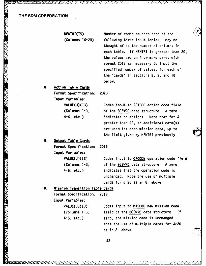
NENTRI(1S) Number of codes on each card of the
(Columns 16-20) following three input tables. May bethought of as the number of columns in
each table. If NENTRI is greater than 20,
the values are on 2 or more cards with
vormat 2013 as necessary to input the
specified number of values, for each of
the 'cards' in Sections 8, 9, and 10
below.
8. Action Table Cards
Format Specification: 2013
Input Variables:
VALUE(J)(13) Codes input to ACTCOD action code field
(Columns 1-3, of the BGSWRD data structure. A zero
4-6, etc.) indicates no actions. Note that for J
.greater than 20, an additional card(s)
are used for each mission code, up to
the limit given by NENTRI previously.
9. Output Table Cards
Format Specification: 2013
Input Variables:
VALUE(J)(13) Codes input to OPCODE operation code field
(Columns 1-3, of the BGSWRD data structure. A zero
4-6, etc.) indicates that the operation code is
unchanged. Note the use of multiple
cards for J 20 as in 8. above.
10. Mission Transition Table Cards
Format Specification: 2013
Input Variables:
VALUE(J)(13) Codes input to MISCOD new mission code
(Columns 1-3, field of the BGSWRD data structure. If
4-6, etc.) zero, the mission code is unchanged.
Note the use of multiple cards for J>20
as in 8. above.
42
i1*. . . . . . . . .. . . . . . . . . . ...................... :..:..:.. . ............ .. ....... ,.:.....,
THE BDM CORPORATION
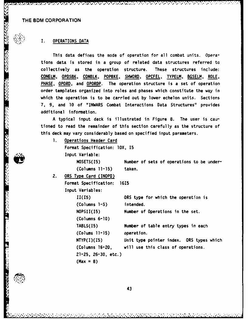
,. I. OPERATIONS DATA
H: This data defines the mode of operation for all combat units. Opera-
tions data is stored in a group of related data structures referred to
collectively as the operation structure. These structures include:
CONELM, OPDSBK, CONBLK, POPBKE, SHWORD, OPCFEL, TYPELM, BGSELM, ROLE,
PHASE, OPORD, and OPORDP. The operation structure is a set of operation
order templates organized into roles and phases which constitute the way in
which the operation is to be carried out by lower echelon units. Sections
7, 9, and 10 of "INWARS Combat Interactions Data Structures" provides
additional information.A typical input deck is illustrated in Figure 8. The user is cau-
tioned to read the remainder of this section carefully as the structure of
this deck may vary considerably based on specified input parameters.
1. Operations Header Card
Format Specification: lOX, 15
... , Input Variable:
NOSETS(15) Number of sets of operations to be under-
(Columns 11-15) taken.
2. ORS Type-Card (INOPD)Format Specification: 1615
Input Variables:
11(15) ORS type for which the operation is
(Columns 1-5) intended.
NOPSII(15) Number of Operations in the set.
(Columns 6-10)
TABLS(I5) Number of table entry types in each
(Colums 11-15) operation.
NTYP(I)(15) Unit type pointer index. ORS types which
(Columns 16-20, will use this class of operations.
21-25, 26-30, etc.)
(Max = 8)
-5 43

THE BDMV CORPORATION
PARAMETERCCAD
OPERTIOATAIONARD
CAARD
m 00100 00
4..1
CAR 44'0000. 0. A D
24 '0
4R7 00

THE BDM CORPORATION
S , 3. Operation Parameters Cards (INOPD)
Eight cards for each operation.
a. Card Type 1
I. Format Specification: 13, IX, A6, FlO.2, 513, 415
Input Variables:
OPNO(13) Operation number-indexes pointer.
(Columns 1-3)
OPNAME(A6) Six character name for the operation.
(Columns 5-10)
FSPEED(FIO.2) Basic speed for "normal" conditions for
(Columns 11-20) this operation prior to modifications.
SRCHNO(I3) Identifies type of perception/search/
(Columns 21-23) disposition pattern used if no search
defined on a basis of unit type.
ALTENO(I3) Operation code of an alternate operation
(Columns 24-26) to be implemented if the assigned operation
0is not suitable. (For units which planonly.)
NROLES(13) Number of roles in the operation struc-
(Columns 27-29) ture. (Zero if unit doesn't plan underthis ORS.)
NPHASE(13) Number of phases in the operation struc-
(Columns 30-32) ture. (Zero if unit doesn't plan under
this ORS.)
UNREQ(13) Number of units required to implement the
(Columns 33-35) operation. (Planned operations only.)
STRREQ(15) Strength requested. (Not used.)
(Columns 36-40)
FRCERQ(15) Force requirements in units of strength.
(Columns 41-45) (Used in planning only.)
EFFREQ(15) Effectiveness requirement for the force as
(Columns 46-50) a whole. Force effectiveness is a weighted
average for all elements of the force.
45
,.. ... - -.-. - ., .-. , - . . -.** *... . .. -.-... ,... -..-. .- ..-. - .- .. .-- . - .- , -
THE BDM CORPORATION
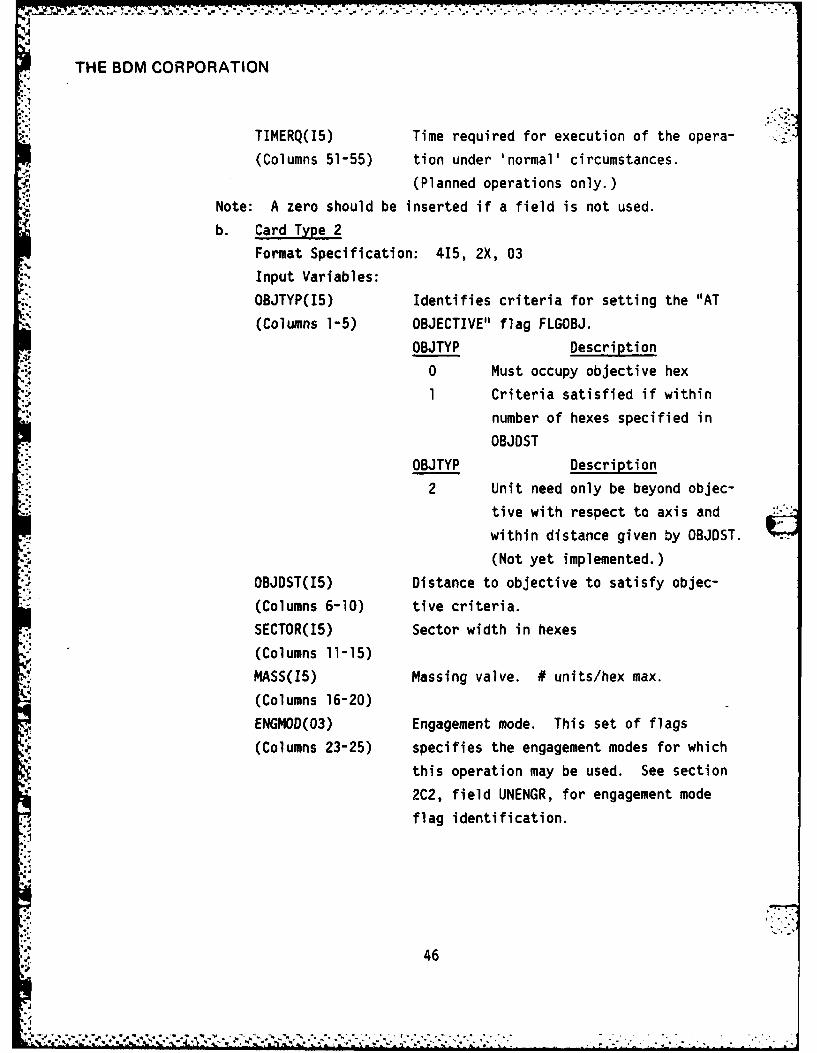
TIMERQ(15) Time required for execution of the opera-
(Columns 51-55) tion under 'normal' circumstances.
(Planned operations only.)
Note: A zero should be inserted if a field is not used.
b. Card Type 2
Format Specification: 415, 2X, 03
Input Variables:
OBJTYP(I5) Identifies criteria for setting the "AT
(Columns 1-5) OBJECTIVE" flag FLGOBJ.
OBJTYP Description
0 Must occupy objective hex
1 Criteria satisfied if within
number of hexes specified in
OBJDST
OBJTYP Description
2 Unit need only be beyond objec-
tive with respect to axis and
within distance given by OBJDST.
(Not yet implemented.)
OBJDST(I5) Distance to objective to satisfy objec-
(Columns 6-10) tive criteria.
SECTOR(I5) Sector width in hexes
(Columns 11-15)
MASS(15) Massing valve. # units/hex max.
(Columns 16-20)
ENGMOD(03) Engagement mode. This set of flags
(Columns 23-25) specifies the engagement modes for which
this operation may be used. See section
2C2, field UNENGR, for engagement mode
flag identification.
46
46

THE BDM CORPORATION
C. Card Type 3
Format Specification: 1015
Input Variables:
SUPTYP(I5) Asset type which is expended at a constant
(Columns 1-5) rate per interval.
SUPRAT(15) Quantity of the asset SUPTYP expended per
(Columns 6-10) unit time.
SUPLEV(15) Quantity of asset SUPTYP needed for
(Columns 11-15) unimpaired operation. At lower levels
the speed of the unit is multiplied by
proportion remaining times the factor
MOVSUP.
SUPLV1(15) Quantity of asset SUPTYP which is a
(Columns 16-20) threshold for setting the supply flag.
POLTYP(I5) Identifies an asset type which is
(Columns 21-25) expended in conjunction with unit movement.
""" tPOLRAT(I5) Amount of the asset POLTYP expended per
(Columns 26-30) hex moved.
POLLEV(I5) Quantity of the asset POLTYP necessary
(Columns 31-35) for unimpaired operations. At lower
levels the speed of the unit is multiplied
by the proportion remaining times the
factor MOUPOL.
POLLVI(I5) Threshold for FLGPOL.
(Columns 36-40)
OTHERI(I5) Extra (not used).
(Columns 41-45)
- OTHER2(I5) Extra (not used).
(Columns 46-50)d. Card Type 4 (5 Cards)
Format Specification: 8F7.3
Input Variables:
VALUE(J) This parameters affect various processes
(Columns 1-7, in the model. They are listed below in
*47
. . . . .

THE BDM CORPORATION
8-14, etc.) order of entry. The maximum allowed
value is 7.99.
1) Combat Computation Effects
The following parameters are applied during the compu-
tation of attrition and suppression effects: They are listed in the order
of input of the corresponding value (J) as described above.(1) ATRFT - Terrain utilization, the extent to which the unit uti-
* lizes terrain for protection.
(2) ATRFR- The extend to which rivers, if present, affect combat
results suffered.
(3) ATRFBH - The extent to which occupying a barrier hex affects
combat results suffered.
(4) ARTFBS - The extent to which a barrier hex side between firing
and target units affects combat results suffered.
(5) ATRFN - The effect of terrain on nuclear weapon combat effects.(6) ATRFC - The effect of terrain on chemical weapon combat effects.
(7) ATRFNV - Nuclear vulnerability, factor.
(8) ATRFCV - Chemical vulnerability factor.
2) Movement Direction Weighting EffectsThe following factors are coefficients in the scoring
equation used to choose the next hex during movement.
(1) MDWSPD - Weighting factor for speed expected to candidate
direction.(2) MOWTHR - Weighting factor for enemy threat, where threat is the
negative enemy to friendly force ratio.
(3) MDWOBJ - Weighting factor for direction to objective, where the
direction component is 90 minus the angle between the candidatedirection and a straight line to the objective.
(4) MDWMAS - Weighting factor for massing of friendly forces, where
the massing effect is the negative of the difference between
friendly strength in the hex and desired massing, MASS, divided
b p..
b 1.'.0.
48
* L- -
THE BDM CORPORATION
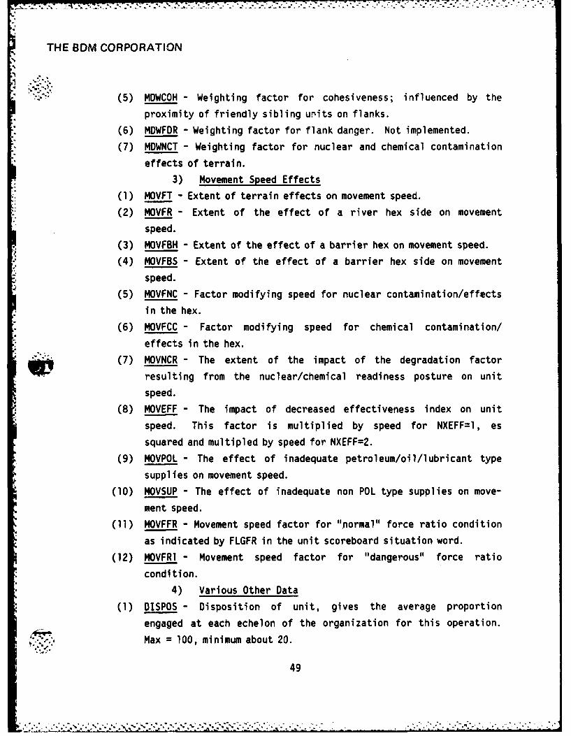
(5) MDWCOH - Weighting factor for cohesiveness; influenced by the
proximity of friendly sibling urits on flanks.
(6) MDWFDR - Weighting factor for flank danger. Not implemented.
(7) MDWNCT - Weighting factor for nuclear and chemical contamination
effects of terrain.
3) Movement Speed Effects
(1) MOVFT - Extent of terrain effects on movement speed.
(2) MOVFR - Extent of the effect of a river hex side on movement
speed.
(3) MOVFBH - Extent of the effect of a barrier hex on movement speed.
(4) MOVFBS - Extent of the effect of a barrier hex side on movement
speed.
(5) MOVFNC - Factor modifying speed for nuclear contamination/effects
in the hex.
(6) MOVFCC - Factor modifying speed for chemical contamination/
effects in the hex.
(7) MOVNCR - The extent of the impact of the degradation factor
resulting from the nuclear/chemical readiness posture on unit
speed.
(8) MOVEFF - The impact of decreased effectiveness index on unit
speed. This factor is multiplied by speed for NXEFF=l, es
squared and multipled by speed for NXEFF=2.
(9) MOVPOL - The effect of inadequate petroleum/oil/lubricant type
supplies on movement speed.
(10) MOVSUP - The effect of inadequate non POL type supplies on move-
ment speed.
(11) MOVFFR - Movement speed factor for "normal" force ratio condition
as indicated by FLGFR in the unit scoreboard situation word.
(12) MOVFRI - Movement speed factor for "dangerous" force ratio
condition.
4) Various Other Data
(1) SPOS - Disposition of unit, gives the average proportion
engaged at each echelon of the organization for this operation.
Max = 100, minimum about 20.
49
S ,, . % • , - *° % "* . ". . *% ,\ - . - . •. ... . , - . .. . . .

THE BDM CORPORATION
(2) EEVALF - Enemy evaluation factor: During the summation of Threat
and flank threat indicies, friendly forces are weighted -1. This
factor determines the weighting for enemy units.
(3) SRECOV - Suppression recovery rate for unit.(4) ERECOV - Effectiveness recovery rate for reconstitution, applied
only when unit is not in contact with enemy units.
* 5) Perception Effects
- (1) EFF1 - Breakpoint for marginal effectiveness, in fraction of base
strength.
(2) EFF2 - Breakpoint for negligible effectiveness, in fraction of
base strength.
(3) EFF3 - Breakpoint for unit dissolution EFF4 breakpoint (undesig-
nated)
(4) EFF4 - Breakpoint (undesignated).
(5) FLDANG - Value of the respective flank threat indices which will
result in the flags FLGFLL or FLGFLR being set.
(6) FRNORM - Force ratio (enemy/friendly) which, if exceeded, results
in the flag FLGFR in the unit situation word being turned on to
indicate a "normal" force ratio.i"4 (7) FRDANG - Force ratio (enemy/friendly) which, if exceeded, results
4 in the flag FLGFRI in the unit situation word being turned on to
indicate a "danger" situation.
(8) OTHER3 - Unused at this time.
.4 4. Role Parameter Cards (I per Role) (INPOST)
Format Specification: 13, lX, A6, 413, 2X, 02, 13, 17, 213, 2X,
07, 15, 3X, 02, 4X, 01, 15
Input Variables:
ROLEID(I3) Role identification number. Also points
(Columns 1-3) to an element ROLEM in the array ROLARY
which governs the aggregation and processing
of situation information.
* NAME(A6) Name of the role.
(Columns 5-10)
50
4*.4. , . -, . . . % . .. , . ,,. = . • . . . . , . .. . , .

THE BDM CORPORATION
ELEMENTS(13) Number of force elements (units) which
(Columns 11-13) may be allocated to this role.
TYPE(13) Type of unit required for this role.
(Columns 14-16)
CLASRQ(13) Classification identity requested. This
(Columns 17-19) is the classification of unit preferred
in the role. Ground unit types as
follows:
* 1. Armor/tank
2. Mechanized
3. Infantry
4. Mech. Cavalry
5. Artillery
6. Air Defense
7. Support
CRITEL(I3) Number of force elements (units which are
(Columns 20-22) critical to the performance of this role.
FLGS(02) Field of one bit flags.
(Columns 24-25)
Bit Name Description
r 0 OBJTYP Objective type.
1 FLGDEF Default role for units not able to
assume other roles.
2 FLGTMP
3 FLGLST Order should be put at end of order
element list.
4 FLGCRT Indicates role critical to operation
(must be filled).
5 FLGCLA Classification flag. Indicates, if
on, that the correct classification
of unit in the role is essential.
BGSID(I3) Applicable ORS identification for the
(ColUmns 26-28) subordinate unit.
51

-1WAMT: - --7-. -..-7.----- -1-7. -
THE BDM CORPORATION
STRNGT(17) Minimum required force for the role, in
(Columns 29-35) units of asset effectiveness.
SECTW(13) Sector width in hexes.
(Columns 36-38)
OBJTYP(13) Objective type (0-1).
(Columns 40-46)
HEXOBJ(07) Immediate hex objective from which a unit
-2 in this role would depart. This orients
the role position with respect to the
parent unit position. Relative to parent
unit center of mass.
EFFREQ(15) Effectiveness state required of a unit
(Columns 47-51) to be assigned to this role.
FLAGS(02) Field of flags relating to the unit's
(Columns 55, 56) order element ORDEM when the operation
is implemented.
Bit Name Description
0-2 Undefined3 FLGCBT Identifies an order element to be
5. used for combat calculations.
4 FLGPER Perception function only.
5 FLGLST identifies last element.
DISROL(Ol) Disposition role. This identifies the
(Column 61) type of role according to its disposition:
1: Left flank
2: Right flank front
0: Center
3: Rear/reserve/Hq, etc.
NEVAL(I5) Number of evaluation elements to follow.
(Columns 62-66) If zero, no evaluation elements are
inputted.
52N4 52
.4
. ..
THE 6DM CORPORATION
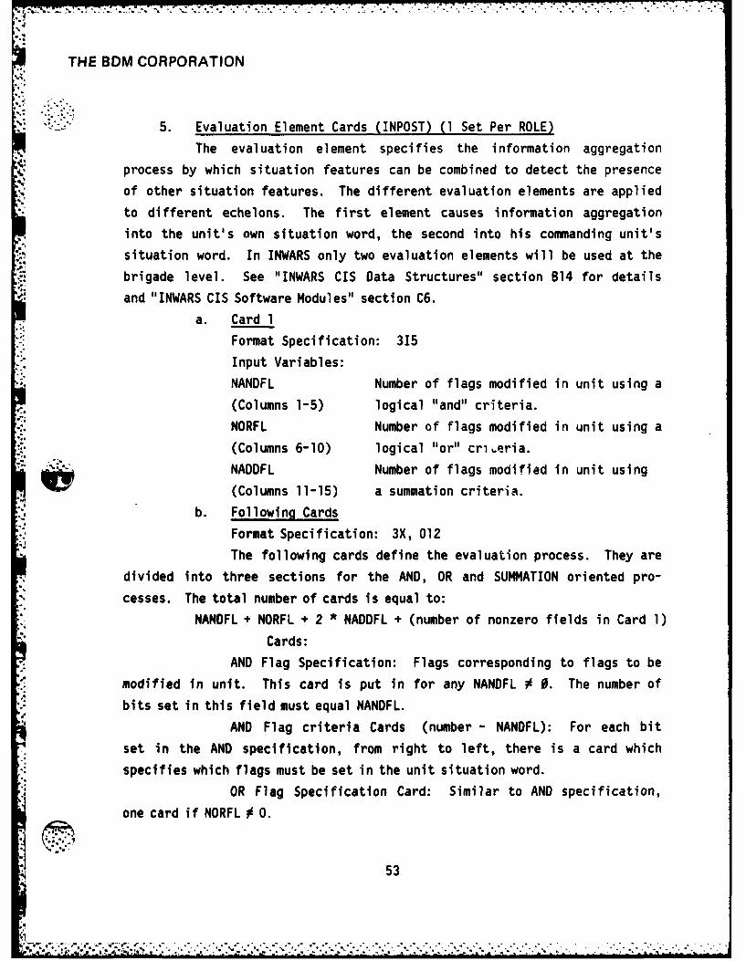
5. Evaluation Element Cards (INPOST) (1 Set Per ROLE)The evaluation element specifies the information aggregation
1"
process by which situation features can be combined to detect the presenceof other situation features. The different evaluation elements are applied
to different echelons. The first element causes information aggregation
into the unit's own situation word, the second into his commanding unit's
situation word. In INWARS only two evaluation elements will be used at the
brigade level. See "INWARS CIS Data Structures" section 814 for details
and "INWARS CIS Software Modules" section C6.
a. Card 1
Format Specification: 315
Input Variables:
. NANDFL Number of flags modified in unit using a
(Columns 1-5) logical "and" criteria.
NORFL Number of flags modified in unit using a
(Columns 6-10) logical "or" criteria.
NADDFL Number of flags modified in unit using
(Columns 11-15) a summation criteria.
b. Following Cards
Format Specification: 3X, 012
The following cards define the evaluation process. They are
divided into three sections for the AND, OR and SUMMATION oriented pro-
cesses. The total number of cards is equal to:
NANDFL + NORFL + 2 * NADDFL + (number of nonzero fields in Card 1)
Cards:
AND Flag Specification: Flags corresponding to flags to be
modified in unit. This card is put in for any NANDFL 0 0. The number of
bits set in this field must equal NANDFL.
AND Flag criteria Cards (number - NANOFL): For each bit
set in the AND specification, from right to left, there is a card which
specifies which flags must be set in the unit situation word.
OR Flag Specification Card: Similar to AND specification,
one card if NORFL 0 0.
53
. . . . . . .................................. ... . " .... . ..

THE BDMV CORPORATION
OR Flag Criteria Cards (number = NORFL).
ADD Flag Specification: Similar to AND specification, one
card i f NADDFL 0 0.ADD Flag Sum Component Cards (number = 2 0 NADDFL): For
each ADD flag, from right to left, there are two cards. A bit set in the
first indicates a 1, and in the second indicates a 2, which are summed if
-; the respective flag is on.6. Phase Card (I for Each Phase)
Format Specification: 13, IX, A6, 13
Input Variables:
PHASID(I3) Phase identification number.
(Columns 1-3)
NAME(A6) Name of phase.
(Columns 5-10)
TIME(13) Amount of time, in combat cycles, that
(Columns 11-13) normally would be needed for a given
phase of the operation.
7. Role Card (1 per Role)
Format Specification: 215
Input Variables:
PRIRTY(IS) The priority of the role during the phase.
(Columns 1-5) Gives a relative importance to the overall
accomplishment of the mission.
RESOUR(I5) The relative priority of the role with
(Columns 6-10) respect to the allocation of resources.
8. Order Card (INPORD)
Format Specification: 15, 3X, 07, 815Input Variables:
MISCOD(I5) Mission code for the type of mission to
(Columns 1-5) be carried out by the unit.
* HEXOBJ(07) Hex address of the objective defined for
(Columns 8-15) the unit in this operation order. Rela-
tive to the hex given in the role defi-
nition.
54
:r-. ,,:,"- ,:' ,' ,. . ,r " .,- ,...C 4 . ,,,. . ,, .'. . . .. : ". "% .-- .- , " . - ," - ". • - • ." ." .- - .:: :, - :_ .

THE BDM CORPORATION
AXIS(I5) Axis of operation. Azimuth angle expressed
(Columns 16-20) as an integer number of degrees clockwise
from north, which orients the unit's
operation.
SECTOR(I5) Sector width of the unit in hexes.
(Columns 21-25)
TIME(I5) Timer which can be used to specify an
(Columns 26-30) interval over which the operation is
effective.
NCONTS(I5) Number of contingency pointers.
(Columns 31-35)
ROLEID(I5) Identification number which specifies the(Columns 36-40) role filled by the unit in a multi-unit
coordinated operation being conducted at
the next higher echelon. It affects the
manner of info aggregation.
FLGTMP(15) Flag which specifies that the operation
(Columns 41-45) order pointed to is in template form.
(see FLGCTM below)NTEMP(15) Number of template order if it is to be
(Columns 46-50) referenced.
FLGOBJ(15) (Always zero)
(Columns 51-55)
9. Contingency Card (INPORD) (If NCONTS # 0 in Previous OPORDER)Format Specification: 515
Input Variables:
CONID(I5) Contingency identification which causes
(Columns 1-5) the associated contingency operation
order to be implemented. Defines con-
tingency in terms of the situation.
SITCOD(15) Situation code which causes the contin-
(Columns 6-10) gency order to be implemented. The con-
tingency order will be used if either the
55
I

THE BDM CORPORATION
contingency is recognized or the situation
code matches that computed from the cur-
rent situation.
CONDC(I5) Contingency disposal code.
(Columns 11-15) CONDC Disposition
0 Do not dispose of contingency,4/ order.
1 Dispose of contingency order.
2 Attach contingency to the new
current order when a "push" is
executed.
3 Attach contingency to the new
current order when a "pop" or
contingency is executed.
FLGCTM(15) This flag, if nonzero, specifies that the
(Columns 16-20) operation order pointed to is in template
form. This means it has not been oriented ,
or detailed for the unit. The use of
template orders allows one copy to exist
which may be referred to by the order
structures of many units, thus saving
space. When a template order contingency
is implemented, a copy of the template
order is made, and the hex objective,
axis, and node ID are changed to those
appropriate to the unit's actual orienta-
tion and location. FLGCTM is also used
to indicate linkage to the following phase
if a 2 is put in. A 3 indicates that the
contingency is the template given by NTEMP.
NTEMP(15) Number of template order.
(Columns 21-25)
56

THE BDM CORPORATION
1,. ono' each contingency with a value FLGCTM equal to zero orone, an operation order card (see section 9 above) follows. Thus the
operation orders form the nodes of a tree structure, and the contingencies
s1 form the branches (although the branches may not have nodes put in at the
same time; if a value of FLGCTM = 2 or 3, the node (OPORDER) is a template
put in a later phase or as an earlier template.
10. Equivalent Operations Card (INOPO)
Format Specification: 1615
Input Variables:
FVALUE(J)(15) Equivalent operations for a unit in this
K = NOSETS operation if engaged by or engaging an
(Number of enemy unit under a different operation
sets of opera- class (e.g., air units attacking ground
tions (Columns units).
1-5, 6-10, 11-15
16-20, etc.)
... 11. Operations Tables Cards (1 for Each Table Entry Type
Format Specification: 16F5.2
Note that if there are more than 16 operations in the set, then
there are more than one card read for each table. Thus, for three tables
and 20 operations, 6 cards would be read using 16F5.2, 4F5.2, 16F5.2,
4F5.2, 16F5.2, and 4F5.2 respectively.
Input Variables:
VALUE(J)(F5.2) Operations table entries. First table is
(Columns 1-5, 6-10, for attrition, second for suppression,
11-15, 16-20 etc.) third for allocation.
J. CONTINGENCY DATA
The contingency data cards are used to specify the conditions under
which a contingency code is recognized. It is stored in the contingency
array and accessed when required to check whether a contingency order
should be executed. See "INWARS CIS Data Structures" section B13 and
."INWARS CIS Software Modules" section Clf for details on this data.
57
THE BDM CORPORATION
1. Contingency Parameter Card
Format Specification: 10X, 15
Input Variable:
NCONTS(I5) Number of contingencies.
(Columns 11-15)
2. Contingency Data Cards (1 for Each Contingency)
Format Specification: 215, 3X, 012, 3X, 012, 3X, 012, 15
Input Variables:
PCONT(15) Pointer to contingency descriptor.
(Columns 1-5)
CONSIT(15) Situation code which will result in
(Columns 6-10) recognition of the contingency.
CAFLGS(012) Set of flags corresponding to those in
(Columns 14-25) the unit situation work which must be on
for the contingency to be recognized.
COFLGS(012) The on flags in this word must be off in
(Columns 29-40) the unit situation word to allow contin-
gency recognition.
PCONEL(I5) Pointer to another contingency which also
(Columns 41-45) will result in the recognition of the
given contingency.
K. HEX DATA
Hex data describes the characteristics of the geographic area in which
combat occurs. Information on terrain and trafficability is stored in a
tree data structure based on hex blocks (HEXBLK). Various levels in the
tree structure correspond to particular size hexes. For the purposes of
data input it is important to note that this tree structure eliminates the
need for specification of a great deal of lower level hex data. A hex data
card need be present only if it or one of its daughters has terrain
characteristics which are different from its parent. For a more detailed
explanation of the hex data structure see Section 4 of "INWARS Combat
Interactions Data Structures."
58
-*-... .. ................... ...... .........

THE BDM CORPORATION
The hex input deck structure is illustrated in Figure 9.1. Hex Data Cards (1 for Each Specified Hex)
-*' Format Specification: IX, II, IX, 07, 15, 2X, 31, 2X, 3I1, 315,
12, 13
Input Variables:
EFLAG(Il) Input flag which indicates hex input status.
(Column 2) 0 = more hex cards follow
1 = last hex card
HEXLOC(07) Hex location. A seven digit code which
(Columns 4-10) specifies the unique location and levelof the hex.
TERTYP(15) Identifies the basic type of terrain in
(Columns 11-15) the hex.Value Type
0 Not used
1 Clear
2 Marginal for vehicles
3 Difficult
4 Urban
5 Impassable (Sea)
6, 7 Undefined
RIVI(Il) Flags indicating whether rivers exist on
(Column 18) hex sides which are in the 3, 2 or 1
RIV2(Il) directions, respectively.
(Column 19)
RIV3(Ii)
(Column 20)
BARI(Il) Flags indicating whether barriers exist
(Column 23) on hex sides which are in the 3, 2, or 1
BAR2(Il) directions, respectively.
(Column 24)
BAR3(Il)
(Column 25)
59
................................... IOU..

THE BDM CORPORATION
-.
-- 1 777777 4 100 000 000
-LAST CARD
,5
.4 - FIRST CARD
IFigure 9. Hex Input Deck
60* -. t. -

S4 2..N.. - . .* * Y- .7--- -
THE BDM CORPORATION
.$:,,, BHEX(15) Indicates whether the hex as a whole
(Columns 26-30) constitutes a barrier.
BTYP(15) Barrier type. Distinguishes between two
(Columns 31-35) types of barriers.
POPULA(I5) Defines population density. The follow-
(Columns 36-40) ing values are currently in use:
I less than 250/km2
3 250 to 1000/km2
5 over 1000/km2
SIDE(I2) Gives nationality side (0 = neutral,
(Columns 41,42) 1 = NATO, 2 = PACT, 3 = none)
NATION(I3) Nationality for given side:
(Columns 43-45) SIDE NATION
0 1 2
AU US SU 0
SZ WG EG 1- BR PO 2- FR CZ 3- BE HU 4- NE - 5- IT - 6- ON - 7
-,
L. ENTITY ASSIGNMENT DATA
This data defines combat entities, including physical data such aslocation and asset types possessed by the unit. It also includes operation
data and initial assignment of ORS types and appropriate operation codes.
More detailed information is contained in Sections 1, 2, 3, 5, 8, 9, and 10
of "INWARS Combat Interactions Data Structures."
61
5-- 6
gi

THE 8DM CORPORATION
A typical input deck structure is illustrated in Figure 10.
1. Flag Card (ENTYIN)
Format Specification: lOX, 15
Input Variables:
FLG(15) Indication of new or additional units.
(Columns 11-15) 0 = Reinitialize unit numbers
I = Do not reinitialize
2. Unit Scoreboard Data Card. Format Specification: 2X, (4Il, 12), 2X, (41l, 12), 412, IX, 07,
IX, 01, IX, 611, 312, 2X, (411, 12), 13,
15
Input Variables:
UNITID(4II, 12) A multi-field unit identifier consisting
(Columns 3-8) of the following fields:
(1) SIDE(Il) 1 for NATO, 2 for WPACT.
(2) ARMYGP(Il) Front or army group identi-
fication, from 1 to 9.
(3) CORPS(I1) Army or corps identifica-
tion, from 1 to 9.
(4) DIVISN(Il) Division identification
from 1 to 9.
(5) BRIGAD(I2) Brigade or regiment ident-
ification, from 1 to 14.
Note: Side must be zero for template
unit.
CMRID(4II, 12) Commander's identification. Used to con-
(Columns 11-16) struct C2 tree. Unit identified must
have been previously input. Zero if no
commander unit (such as for a template).TYPE(12) Unit type identification. While the type
(Columns 17,18) categories can be assigned by the user
during initial data input, the following
type identifications are now being used.
62
-f....................................-. *. .

THE BDM CORPORATION
UNIT ~ ~ EN SCCAORDRDDSECONDCONORDERCA Y CARD
IOPTIONA)CONTPNENONCARFIRSTODE ORDRAARDS
BASIC DATA CARD-S. _
ASSET DATAADS e,_0~NI UNOEBAT SCREOAD 10000 000 13400000CARD RE CRSEOO
*~~ SEC,~0
SEFigur 10.I Entit CnARt DeckT
JOPTONALCONTNGENY CA
FIRST.........................................

THE BDM CORPORATION
Value Type
1 Echelon above division
2 Division headquarters
3 Ground maneuver or air defense
unit
4 Logistics
5 N/C supply point
6 Air base cluster
7 Air mission package
8 Weapon delivery package
15 Nuc/chem effects entity
CLASIF(12) Further identifies type of unit. It is
(Columns 19,20) used by the model to identify appropriate
Cunits for roles during mission planning
and to define units symbols for graphicsoutput. While these types can be redefined
by the user, the following are now in use.
Value Type
1 Armor/tank
2 Mechanized
3 Infantry
4 Mech. cavalry
5 Artillery
6 Air Defense
7 Support
ECHLON(12) Identifies the echelon of the unit within
C, (Columns 21,22) the command structure.
Echelon Side=NATO Pact
6 Theater Theater
5 Army Gp Front
4 Corps Army
3 Division Division
2 Brigade Regiment
1 Detachment -
0 - -
64

- . *..*.***°.o°*. * * -
THE 6DMV CORPORATION
NATION(12) Identifies nationality.
(Columns 23, 24) Nation Side=NATO Pact
0 us SU
I I WG EG
2 BR PO3 FR CZ
4 BE HU
5 NE --
6 IT --
7 DN --
HEXLOC(07) Defines hex location of the unit in the
(Columns 26-32) hexagonal array. The hexagonal coordinate
system is described in the INWARS Level
III Specifications; Volume I.
FACING(Ol) Octal digit indicating an orientation of
(Column 34) the unit, which is not necessarily the
o - same as the movement direction. Itorients the search (perception) pattern
of the unit.
Ll(Il) Identify hex levels in which unit is
(Column 36) initially located.
L2(II)
(Column 37)
L3(Il)
(Column 38)
L4(141)
(Column 39)
L5(11)'"' (Col umn 40)~L6(II)
(Column 41)
NORDPT(I2) Number of ORS's of a unit and number of
(Columns 42,43) concurrent operation orders.
65

9,.
THE BDM CORPORATION
NASSET(12) Number of assets in the asset list.
(Columns 44,45)
*I FASSET(12) Asset flag. If zero, assets follow. If
(Columns 46,47) 1, copy assets of unit identified inASSREF.
ASSREF(41l, 12) Reference unit for asset list if FASSET = 1.
(Columns 50-55)
FLGCCI(I3) Indicates unit has special capabilities.
(Columns 56-58) One for EAD Hq units, air base cluster,
logistics, and weapons delivery entities,
zero for others.
FLGTMP(I5) If nonzero, indicates a template unit.- (Columns 59-63) The value is the template number of the
unit.
The template numbers currently defined are:
Template Number Unit Type
1 NATO Close Air Support
Air Mission Package
2 PACT Close Air Support
Air Mission Package3 NATO Interdiction Air
Mission Package
4 PACT Interdiction Air
Mission Package
5 NATO Nuclear Munitions
Package
6 PACT Nuclear Munitions
Package
7 NATO Chemical Munitions
Package8 PACT Chemical Munitions
Package
All eight of these template units must be
defined in the entity input deck. It is
66
.4

THE BDM CORPORATION
normal practice to put them together at
either the start or end of the deck. All
template units should have a uni ID start-
ing with ooo. These templates specify
the types of entities which are created
for air, nuclear, and chemical packages.
3. Asset Data Cards (1 for Each Asset. A Unit has NASSET.)
Format Specification: 15, FlO.2
Input Variables:
ASTYP(15) Asset type. Index which refers to
(Columns 1-5) appropriate asset description.
FNUMBR(FlO.2) Number of assets of a given type which
(Columns 6-15) a unit has.
4. Basic Cata Cards (1 for Each Order)
Format Specification: 215, 3X, 02
Input Variables:
ORSID(I5) ORS which governs unit's operations.
(Columns 1-5)
OPCODE(I5) Operation code which identifies a partic-
(Columns 6-10) ular operation posture for the unit. The
codes are user specified. See Section
VI, User's Manual. (Initial OPCODE only.)
FLAGS(02) This field includes the following bit
(Columns 14,15) flags.
Bit Name Description
0-2 -- Undefined
3 FLGCBT Identifies an order element to be
used for combat computations.
4 FLGPER Perception function only
5 FLGST Identifies last element
5. Order Card
Format Specification: 15, 2X, 811, 815
67

THE BDM CORPORATION
Input Variables:
MISCOD(I5) Mission code for the type of mission to
(Columns 1-5) be carried on by the unit.HEXOBJ(711) Hex address of the objective defined for
(Columns 9-15) unit in this operation order. If the
order is a template, this is a relative
objective and thus should have leading
zeros (rather than leading sevens asnormal). If FLGOBJ = 1, the objective
is unit-centered and not a template.
The input is equivalent to 411, 12, where
the first 6 digits are the unit ID of the
objective. The referenced unit must have
been put in previously.AXIS(I5) Axis of operation. Azimuth angle expressed
-' (Columns 16-20) as an integer number of degrees clockwise
from north, which orients the unit's
operation.
SECTOR(I5) Sector width of the unit in hexes.
(Columns 21-25)
TIME(I5) Timer which can be used to specify an
(Cdlumns 26-30) interval over which the operation order
is effective.NCONTS(I5) Number of contingency pointers.
(Columns 31-35)
ROLEIO(I5) Identification number which specifies the
(Columns 36-40) role filled by the unit in a multi-unit
coordinated operation being conducted at
the next higher echelon. It affects the
manner of info aggregation.
FLGTMP(15) Flag which specifies that the operation
(Columns 41-45) order pointed to is in template form.
(See FLGCTM.)
68

THE BDM CORPORATION
NTEMP(I5) Template number, if FLGTMP = 1, may be
(Columns 46-50) nonzero.
FLGOBJ(I5) Objective type. 0 for hex objective,(Columns 51-55) 1 for unit objective.
6. Contingency Card (If Contingency)
Format Specification: 515
Input Variables:
CONID(I5) Contingency identification which causes
(Columns 1-5) the associated contingency operation order
to be implemented. Defines contingency
interims of the situation.
SITCOD(I5) Situation code which causes the contin-
(Columns 6-10) gency order to be implemented. The con-
tingency order will be used if either
the contingency is recognized or the
situation code matches that computed
from the current situation.
CONDC(I5) Contingency Disposal Code.
(Colums 11-15)Code Disposition
0 Do not dispose of contingency order.
1 Dispose of contingency order normally
(release to ISPACE).
2 Attach contingency to the new current
order when a "push" is executed.
3 Attach contingency to the new current
order when a "pop" or contingency is
executed.
FLGCTN(15) This flag specifies that the operation
(Columns 16-20) order pointed to is in template form.
This means it has not been oriented or
detailed for the unit. The use of tem-
plate orders allows one copy to exist
69
W51V V N5% %%Y: '.'8%..:. * .. .. , V

THE BDM CORPORATION
which may be referred to by the order
structure of many units, thus saving
space. When a template order contin-
gency is implemented, a new copy of
the template order is made and the hex
objective, axis, and role ID are changed
to those appropriate to the unit's actual
orientation and location. If FLGCTM = 13,
order is template; if 0, not template.
Do not use 2.
NTEMP(15) Number of template order.
(Columns 21-25)
Note: If FLGCTM = 0 or 1, this contingency must be followed byan OPORDER card as in section 5, above.
7. End Card
Format Specification: 12
Input Variable:
FLAG(12) Option to indicate end of the CIS data
(Columns 1,2) stream: 1 = END. This distinguishes it
from another Entity Input, for which
this entry would be blank (negative
zero).
70
: .- ,-.- ............................. .. .- "....."..."-".".-".."...... ".- - "- ." ' ' ' . " .. "-.-