Embed Size (px)
Citation preview
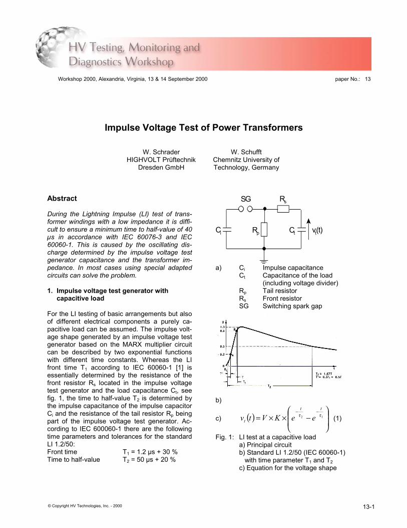
Impulse Voltage Test of Power Transformers
W. Schrader W. SchufftHIGHVOLT Prüftechnik
Dresden GmbHChemnitz University ofTechnology, Germany
Abstract
During the Lightning Impulse (LI) test of trans-former windings with a low impedance it is diffi-cult to ensure a minimum time to half-value of 40µs in accordance with IEC 60076-3 and IEC60060-1. This is caused by the oscillating dis-charge determined by the impulse voltage testgenerator capacitance and the transformer im-pedance. In most cases using special adaptedcircuits can solve the problem.
1. Impulse voltage test generator withcapacitive load
For the LI testing of basic arrangements but alsoof different electrical components a purely ca-pacitive load can be assumed. The impulse volt-age shape generated by an impulse voltage testgenerator based on the MARX multiplier circuitcan be described by two exponential functionswith different time constants. Whereas the LIfront time T1 according to IEC 60060-1 [1] isessentially determined by the resistance of thefront resistor Rs located in the impulse voltagetest generator and the load capacitance Ct, seefig. 1, the time to half-value T2 is determined bythe impulse capacitance of the impulse capacitorCi and the resistance of the tail resistor Rp beingpart of the impulse voltage test generator. Ac-cording to IEC 600060-1 there are the followingtime parameters and tolerances for the standardLI 1.2/50:Front time T1 = 1.2 µs + 30 %Time to half-value T2 = 50 µs + 20 %
Ci CtRp
Rs
vt(t)
SG
a) Ci Impulse capacitanceCt Capacitance of the load
(including voltage divider)Rp Tail resistorRs Front resistorSG Switching spark gap
b)
c) ( )
−××=
−−12 ττtt
t eeKVtv (1)
Fig. 1: LI test at a capacitive loada) Principal circuitb) Standard LI 1.2/50 (IEC 60060-1) with time parameter T1 and T2c) Equation for the voltage shape
Workshop 2000, Alexandria, Virginia, 13 & 14 September 2000
© Copyright HV Technologies, Inc. - 2000
paper No.: 13
13-1

2. Impulse voltage test generator withinductive load
In most of the cases power transformers cannotbe assumed as a purely capacitive load for the LItesting. Usually the LI test voltage is applied toone winding terminal of the transformer to betested, whereas all other terminals are con-nected with the earth. Hereby, not only the inputcapacitance of the transformer winding acts asthe load for the impulse voltage test generatorbut also its impedance to all other short-circuitedwindings. The principal circuit (fig. 1) must beextended by the transformer inductance Lt that isconnected in parallel to the test capacitance Ct(fig. 2).
SG
Ci CtRp
Rs
Lt vt(t)
a) Ci Impulse capacitanceCt Capacitance of the load
(including voltage divider)Lt Inductance of the loadRp Tail resistorRs Front resistorSG Switching spark gap
b)
c) ( ) ( )
∗−−∗∗∗≈
−− τδ ϕωt
tt eKteKVtv 21 cos (2)
Fig. 2: LI test at an inductive/capacitive loada) Principal circuitb) Voltage shape depending on the inductance factor Ltc) Equation for the voltage shape
Thereby the inductance Lt of the load becomessmaller with decreasing impedance voltagevimp%, with decreasing rated phase-to-phasevoltage VP-P and with increasing power Ptot of thetransformer winding to be tested. Therefore thelowest values of the inductance Lt have to beconsidered by testing the low-voltage side wind-ings for power transformers. For a three-phasewinding in a star connection the following equa-tion can be applied:
tot
PPimpt P
VvL
∗∗∗
= −
ω100
2% (3)
ω = 2 π f
Lt Inductance (stray inductance) of thewinding to be tested
vimp% Impedance voltage of the winding to betested
VP-P Rated phase-to-phase voltage of thethree-phase winding to be tested
Ptot Rated total power of the three-phasewinding to be tested
f Rated frequency
With decreasing inductance Lt the impulse ca-pacitance Ci of the impulse voltage test genera-tor is not only discharged via the tail resistor Rp,but also via the low inductance Lt of the windingto be tested. Thereby the time to half-value T2 ofthe LI is reduced and the aperiodic discharge ofthe impulse capacitance turns to a damped os-cillating cosine shape. This is permitted in princi-ple acc. to IEC 60076-3 [2]. However, the lowertolerance limit for the time to half-value of T2 minmay not remain under 40 µs (= 50 µs - 20 %). Atthe other side the amplitude of opposite polarityof the LI voltage dmax should not exceed 50 %.To fulfil these both requirements the impulsevoltage impulse voltage test generator musthave a minimum required impulse capacitanceCi req, which can be calculated closely as follow-ing:
treqi L
TC
2min22∗≥ (4)
with T2 = 40 µs
Hence it follows with equation (3):
2%
2min2 100
2PPimp
totreqi Uv
PTC
−∗∗∗∗
∗≥ω
(5)
Though the requirement for a minimum impulsecapacity Ci req of the impulse voltage test gen-erator is necessary but it is not sufficient to meet
HV Technologies, Inc. - Workshop 2000, 13 & 14 September, Alexandria, Virginia 13-2

the requirements T2 min ≥ 40 µs (IEC) and dmax ≤50 %. Moreover, the oscillating circuit formed bythe impulse capacitance Ci of the impulse volt-age test generator and the winding inductance Ltmust have a certain characteristic damping. Thisis mainly determined by the front and tail resis-tors (Rs, Rp) located in the impulse voltage testgenerator. If the damping is to low, a minimumtime to half-value T2min ≥ 40 µs can be reached,but the amplitude of opposite polarity d is morethan 50 %. For a higher damping the require-ment for the amplitude of opposite polarity d ≤ 50% can be fulfilled, but the time to half-value mayremain smaller than 40 µs, see fig. 3. In the casethat the impulse capacitance of the impulse volt-age test generator Ci is not greater than theminimum required impulse capacitance Ci reqaccording to equation (5), the adjustment of thedamping of the test circuit must be done veryexactly. The margin for the adjustment, i.e. forthe sufficient circuit damping, becomes greaterthe more the impulse capacitance of the appliedimpulse voltage test generator Ci exceeds theminimum required impulse capacitance Ci reqaccording to equation (5).
Fig. 3: LI test of power transformers withdifferent damping of the test circuit
(a), (b): Damping to low - the amplitude of oppo-site polarity d of the LI is to high(d > 50%)
(c): Optimal damping (T2 > 40µs, d < 50%)(d), (e): Damping to high - T2 is to short
(T2 < 40µs)
3. Resistive earthing of windingterminals
If the requirements acc. to equation (5) can notbe fulfilled for the LI test of a power transformerswith an existing impulse voltage test generator,IEC 60076-3 allows for the following exceptions:
a) A shorter time to half-value than T2 = 40 µscan be agreed between the manufacturerand the customer of the transformer
b) Winding terminals being not directly exposedto the test voltage, can be earthed via termi-nation resistors
The resistance of the termination resistors has toremain under 500 Ohm. Furthermore, it has tomade sure that the voltage which will occur atthe resistively earthed winding terminals will notexceed 75 % of the rated LI withstand voltage ofthese windings. With this method it is often pos-sible to extend the operating range of an impulsevoltage test generator considerably. Neverthe-less, it must be noted that hereby, the impulsevoltage stress of the tested windings may con-siderably deviate from the voltage stress fordirect earthing. It has to be agreed betweencustomer and manufacturer which exception isaccepted.
Fig. 4: Impulse Voltage Test System IP 360/3600 G (360 kJ, 3600 kV) with impulsevoltage divider and chopping multiple spark gap,with a stage energy of 20 kJ being used for theLI test of power transformers up to 765 kV
HV Technologies, Inc. - Workshop 2000, 13 & 14 September, Alexandria, Virginia 13-3

4. Projection of an impulse voltage testgenerator for the LI test of powertransformers
The main technical data of the transformers tobe tested, like the circuitry and the arrangementof the windings, their rated voltage, rated power,impedance voltage and not at least the ratedfrequency determine essentially the total charg-ing voltage and the stage energy of an impulsevoltage test generator for the LI test.The total charging voltage of the impulse voltagetest generator should lie for LI testing 30 % … 60% above the highest required LI test voltage. Inmany cases the value of 30 % is sufficient forroutine tests. If development tests are to be car-ried out, a total charging voltage, which lies 60 %above the highest rated LI test voltage, is rec-ommended.If the exception “earthing via termination resis-tors” is not considered, the required impulsecapacitance Ci req can be calculated for eachwinding voltage level acc. to equation (5). Takinginto consideration the different circuitry options ofthe impulse voltage test generator (parallel con-nection of stages, partial operation) and theabove aspects regarding the total charging volt-age the stage charging energy can be calculatedin principle for each possible test case.Normally a stage energy of 5 … 10 kJ per 100-kV-stage and a stage energy of 10 … 20 kJ per200-kV-stage will be sufficient. Whereas thelower values apply to transformers with lowerpower, the higher values apply to transformerswith higher power (fig. 4). Often, impulse voltagetest generators for power transformer testinghave an energy of 15 kJ per 200-kV-stage, seefig. 5.
5. Extension of the loading range of im-pulse voltage test generators
Often it is required to test transformer with sucha high power, for which the existing impulsevoltage test generator has not been originallymeant. In such cases it is necessary to utilise allreserves of the existing impulse voltage testgenerator.
5.1. Increasing the effective impulse ca-pacitance
The following generally known measures can betaken:a) Running the impulse voltage test generator
in partial operation, i.e. with the minimum
number of stages, being necessary to reachthe required test voltage level.
b) Switching a certain number of generatorstages respectively in parallel and connectthis parallel stages in series to reach the re-quired test voltage.
5.2. Increasing the parallel resistors
If the time to half-value remains only a few belowthe permitted lower limit T2 min = 40 µs, it is pos-sible to reach a value of T2 ≥ 40 µs by increasingthe tail resistors Rp. Usually the tail resistorsmeant for switching impulse voltage can be ap-plied. A further increase of the resistance of thetail resistors Rp above the resistance value forthe SI generation does not have any result.
Fig. 5: Impulse Voltage Test SystemIP 150/2000 G (150 kJ, 2000 kV) with impulsevoltage divider and chopping multiple spark gap,with a stage energy of 15 kJ being used for theLI test of power transformers up to 245 kV
5.3. Decreasing the damping of the testcircuit
As already mentioned in chapter 2, if the circuitdamping is to high, a time to half-value of T2 ≥ 40µs is not reached even with a sufficient impulse
HV Technologies, Inc. - Workshop 2000, 13 & 14 September, Alexandria, Virginia 13-4

capacitance of the impulse voltage test genera-tor (Ci ≥ Ci req), see fig. 3.The front and tail resistors in the impulse voltagetest generator are mostly responsible for thatdamping.The damping caused by the tail resistors Rp canbe considerably eliminated by their increase, asalready recommended in chapter 5.2. . For afurther reduction of the damping the resistanceof the front resistor Rs has to be reduced. Thiswould cause a shorter front time T1 of the LI. Tokeep the front time T1 unchanged, the capaci-tance of the load has to be increased corre-sponding to the reduction of the resistance of thefront resistor Rs. This is easily realised by con-necting an additional capacitor in parallel to thetransformer winding to be tested.Unfortunately, the effect of this method is limited,because a reduction of the resistance of the frontresistor Rs will lead to oscillations on the front ofthe LI voltage soon, which may exceed the per-mitted limit for the overshoot of 5 % /1/.
5.4. Application of the ”Glaninger-circuit”
The disadvantage of oscillations on the voltagefront after a reduction of the front resistor Rs iscompletely avoided with a circuit invented byGLANINGER [3]. Hereby the front resistor re-sponsible for the voltage front remains un-changed but it is bridged by an additional induc-tance formed by an air-coil (fig. 6).
SG
Ci CtRp
Rs
Lt vt(t)
Lg
Rt
Ci Impulse capacitanceCt Capacitance of the load
(including voltage divider)Lg Glaninger-coilLt Inductance of the loadRp Tail resistorRs Front resistorRt Resistor in parallel to the load SG Switching spark gap
Fig. 6: Test circuit with Glaninger-circuit (Lg andRt) for LI testing of power transformers with ex-tremely low impedance
The Glaninger-coil must have an inductancevalue ca. 100 … 200 µH, to be ineffective for thefast impulse front and to bridge the front resistorRs during the much longer impulse tail. So hefront of the LI impulse remains unchanged andthe tail is extended. Consequently an additionalresistor Rt has to be switched in parallel to theload inductance Lt, to form a true voltage dividerconsisting of Rs//Lg and Rt//Lt.
Fig. 7: LI test of power transformers by usingthe Glaninger-circuit, adjustment of the voltageshape at the voltage crest by means of an addi-tional resistor Rt (optimal adjustment Rt = 300Ohm for this example)
Fig. 8: LI test of power transformers by usingthe Glaninger-circuit, adjustment of the time tohalf-value T2 and the amplitude of opposite po-larity d by means of the tail resistor Rp (optimaladjustment Rp = 60 Ohm for this example, T2 >40 µs, d < 50 %)
With a Glaninger-circuit the front time T1, thetime to half-value T2 and the amplitude of oppo-site polarity d of the LI test voltage can be setalmost independently, i.e. T1 with the tail resistorRs, T2 and d with the resistors Rp und Rt (fig. 7and 8). A variation of the Glaninger-coil induc-tance is as a rule not necessary. The Glaninger-circuit enables for LI testing the most effective
HV Technologies, Inc. - Workshop 2000, 13 & 14 September, Alexandria, Virginia 13-5

adaptation of the impulse voltage test generatorand the transformer to be tested. An existingimpulse voltage test generator can be utilisedoptimally.
6. Conclusion
The testing of power transformers with LI testvoltage acc. to the IEC standards presupposesspecial knowledge of the interaction between theimpulse voltage test generator and the inductiveload. For example, there exists a close connec-tion between the main data of the transformer tobe tested and the required impulse capacitanceof the impulse voltage test generator. There arealso requirements related to the damping
characteristic of the test circuit to utilise an ex-isting impulse voltage test generator optimally.Some basic aspects and circuitries were de-scribed in this paper.
References
[1] IEC 60060-1 (1989-11), High-voltage testtechniques. Part 1: General definitions andtest requirements
[2] IEC 60076-3 (2000-03), Power transformersPart 3: Insulation levels, dielectric tests andexternal clearances in air
[3] Glaninger, P.: Stoßspannungsprüfungan elektrischen Betriebsmitteln kleiner In-duktivität. ISH Zürich, 1975, Beitrag 2.1-05
HV Technologies, Inc. - Workshop 2000, 13 & 14 September, Alexandria, Virginia 13-6