Embed Size (px)
Citation preview

Improving User Experiences in Indoor Navigation
Using Augmented Reality
Nahush Bhanage
Electrical Engineering and Computer SciencesUniversity of California at Berkeley
Technical Report No. UCB/EECS-2014-73
http://www.eecs.berkeley.edu/Pubs/TechRpts/2014/EECS-2014-73.html
May 14, 2014

Copyright © 2014, by the author(s).All rights reserved.
Permission to make digital or hard copies of all or part of this work forpersonal or classroom use is granted without fee provided that copies arenot made or distributed for profit or commercial advantage and that copiesbear this notice and the full citation on the first page. To copy otherwise, torepublish, to post on servers or to redistribute to lists, requires prior specificpermission.
Acknowledgement
I would like to express my sincere gratitude and appreciation to my facultyadvisors Prof. Björn Hartmann and Dr. Don Wroblewski, industrial advisorJiajian Chen (Qualcomm Research Silicon Valley) and Ph.D. studentadvisor Ben Zhang for their continuous support and motivation throughoutthis project. I would also like to thank my colleagues Xuanyu Zhong andChun-Yuan Yang without whom this project would not have been a reality.Finally, I would like extend my appreciation to all our test users in theCITRIS Invention lab, University of California Berkeley for their time andconstructive feedback.
pg. 1
University of California, Berkeley College of Engineering
MASTER OF ENGINEERING - SPRING 2014
Electrical Engineering and Computer Sciences
Visual Computing and Computer Graphics
Improving User Experiences in Indoor Navigation Using Augmented Reality
NAHUSH NARENDRA BHANAGE
This Masters Project Paper fulfills the Master of Engineering degree
requirement.
Approved by:
1. Capstone Project Advisor:
Signature: __________________________ Date ____________
Prof. Björn Hartmann, Electrical Engineering and Computer Sciences
2. Faculty Committee Member #2:
Signature: __________________________ Date ____________
Dr. Donald Wroblewski, Fung Institute for Engineering Leadership

pg. 2
Improving User Experiences in Indoor Navigation Using Augmented Reality
Nahush Narendra Bhanage
Electrical Engineering and Computer Sciences
University of California, Berkeley
May 2014

pg. 3
Abstract
Indoor positioning systems help in the localization of objects or spaces inside a building, where
Global Positioning System (GPS) and cellular network don’t work effectively. These systems can
be much more useful than just localizing objects, if they are augmented with relevant information
on the user interface. This paper demonstrates, with a prototype, one such use case where an
indoor positioning system can be made more useful by rendering relevant 3D graphics on the
mobile display. It also describes our application development process, right from target user
interviews to an interactive high-fidelity prototype development in Android. Localization is
achieved by creating a location API simulator and using the orientation sensors in the
phone/tablet. Relevant graphical information, determined based on the user’s context and
selection, is rendered using OpenGL on top of the live camera stream. User studies indicated that
overlaying points of interest on the camera view significantly enhanced the user experience in
indoor navigation. Localization can be made even more robust with the help of object detection
techniques. To summarize, there is a strong untapped potential in augmented reality techniques
in the context of indoor navigation and we have attempted to demonstrate this in our
application. Our solution is generic and can be easily configured to be used in any indoor space
such as malls, hospitals, museums etc.

pg. 4
Acknowledgements
I would like to express my sincere gratitude and appreciation to my faculty advisors Prof. Björn
Hartmann and Dr. Don Wroblewski, industrial advisor Jiajian Chen (Qualcomm Research Silicon
Valley) and Ph.D. student advisor Ben Zhang for their continuous support and motivation
throughout this project. I would also like to thank my colleagues Xuanyu Zhong and Chun-Yuan
Yang without whom this project would not have been a reality.
Finally, I would like extend my appreciation to all our test users in the CITRIS Invention lab,
University of California Berkeley for their time and constructive feedback.

pg. 5
Table of Contents
1. Introduction ................................................................................................................................ 8
2. Literature Review ........................................................................................................................ 9
2.1. Technology ........................................................................................................................... 9
2.2. Industry Landscape ............................................................................................................ 11
2.3. What sets us apart? ............................................................................................................ 15
3. Methodology ............................................................................................................................. 15
3.1. Targeting a specific user scenario ...................................................................................... 16
3.2. Developing a mockup user interface ................................................................................. 16
3.3. Developing an interactive prototype ................................................................................. 19
4. Results: User Study ................................................................................................................... 28
5. Conclusion ................................................................................................................................. 30
References .................................................................................................................................... 32

pg. 6
List of Figures
Figure 1: Qualcomm’s IZat [9] ……………………………………………………………………………….……………….… 12
Figure 2: Google's Indoor Navigation [10] …………………………………………………………………..……………. 12
Figure 3: Place Lab UI [13] ……………………………..………………………..……………….………………….…………… 13
Figure 4: Place Lab architecture [12] ……………………………………………………………………………….………… 13
Figure 5: NAVVIS UI [14] …………………………………………………………………………………………………….…….. 14
Figure 6: InfSoft UI [15] ………………………………………………………………………………………………………….…. 14
Figure 7: Balsamiq UI – Apprentice Mode …..………………………..…………….….……………………………… 17
Figure 8: Balsamiq UI – Visitor Mode …..………………………….…..……………..….……………………………… 17
Figure 9: Balsamiq UI – Navigation Mode …..………………………..……………..….……………………………… 18
Figure 10: Balsamiq UI – Calendar Mode …..….……………………..…………….….……………………….……… 18
Figure 11: Modules in our application ……………………………………………….……………………………..……. 19
Figure 12: Our website for the simulated Location API ………………………………………..…………………. 20
Figure 13: OpenGL rendering pipeline [16] …………………………………………….…………………...……………. 21
Figure 14: Interactive Prototype – Basic mode selection ………………………………………..………………. 23
Figure 15: Interactive Prototype – Device selection in ‘World’ mode …………………………..…………. 23
Figure 16: Interactive Prototype – Visitor mode ………………………………………..…………………...………. 24

pg. 7
Figure 17: Interactive Prototype – Apprentice Mode ………………………………………..……………….……. 25
Figure 18: Interactive Prototype – Device Selection in the Navigation mode …………………………... 25
Figure 19: Interactive Prototype – Navigation Mode ………………………………………..…………….………. 26
Figure 20: Interactive Prototype – Calendar mode ………………………………………..……….………………. 27
Figure 21: Interactive Prototype – Google calendar of Afinia ………………………………….……………... 27
Figure 22: User Study: Average Feature Ranks ………………………………………..…………………………….. 28
Figure 23: User Study: Comparison of Augmented Lab with Documented instructions ……….…. 29
Figure 24: User Study: Reasons for choosing Augmented Lab ………………………………………..…….… 29

pg. 8
1. Introduction
Indoor Positioning refers to locating objects or spaces inside a building. Global Positioning System
(GPS) does not work accurately indoors due to signal attenuation and reflection caused by roofs
and walls [1]. Hence in most situations, GPS based location tracking does not produce useful
results. As a result, most of the popular indoor positioning systems work on technologies such as
Wi-Fi, Bluetooth, Radio beacons which are more accurate than GPS. Furthermore, accurate
location determination of indoor spaces could have numerous interesting applications if
integrated with augmented reality. Indoor navigation systems have started incorporating
augmented reality techniques to visually help the user in navigating indoors.
User experience is critical in indoor navigation systems. This is more relevant in large indoor
spaces such as malls, museums, airports etc. where displaying the location on a 2D map would
not necessarily give a good user experience. There is a need for some clear visual indicators to
create an appealing and a convenient experience for the users of such indoor navigation systems.
Maps can only be useful in tracking the location of a person or object whereas with augmented
reality, a lot of relevant information can be displayed along with the location information. There
is a strong untapped potential in augmented reality techniques, with respect to indoor
navigation. Indoor navigation systems can be useful in a variety of interesting applications, apart
from localizing an object or a user indoors. For instance - in the British Museum [2], when a visitor
orients his phone towards a particular painting, relevant information (such as history of the artist,
images of similar paintings etc.) pops up on his screen. This is possible if his relative location in
the museum is known.

pg. 9
In this paper, we demonstrate how augmented reality can enhance the utility of indoor
positioning systems. The Literature Review section gives an overview of the various technologies
used in indoor positioning systems and the existing landscape (key players) in this market. It is
followed by the Methodology section, which describes how we targeted a specific user scenario
and the technologies we used to develop an augmented reality based prototype. We then discuss
the user study results in the Results section. Finally, the Conclusion section summarizes the paper
and briefly discusses possible future work in this area.
2. Literature Review
2.1. Technology
This section gives an overview of some of the most popular technologies used in Indoor
Positioning Systems - Global Positioning System (GPS), Wi-Fi, Bluetooth and Infrared.
GPS
The satellite based GPS is more suitable for positioning outdoors. As mentioned above, it does
not work well in a relatively closed environment due to signal attenuation. Reflections across
different indoor surfaces further reduce the signal accuracy [1].
Bluetooth
Bluetooth is a wireless technology standard used for exchanging data over short distances. It uses
radio waves in the range of 2.4 to 2.483 GHz [3]. The positioning algorithm is based on estimating
pg. 10
the power of radio wave signals received by the device [4]. Using Bluetooth is highly secure, cost
effective and low in power consumption [4]. However it has certain drawbacks. It works over short
distances only, hence a large number of receivers are required to cover a wide area. It runs the
device discovery procedure for each localization attempt, thereby increasing the latency by 10-
30 seconds [4]. Localization systems based on Bluetooth are explained in detail in [5] and [6].
Infrared
Infrared systems are highly accurate short-ranged positioning solutions. In one of the commonly
used positioning techniques, a device is localized with the help of a unique IR signal emitted every
ten seconds by its badge. IR sensors placed at different locations capture these signals and
communicate with a central location management server. However, these systems have high
installation and maintenance costs. [7]
Wi-Fi
Wi-Fi is the most commonly used technology for indoor positioning. Wi-Fi access points are
usually installed in most indoor spaces. Each access point works over a medium range (25-50
meters) [8] which is ideal for indoor positioning. The device’s location is estimated using
vectorization by tracking it relative to the location of access points on the floor.
Table 1 [4] shows a comparative analysis based on accuracy, coverage, power consumption and
cost.

pg. 11
System Accuracy Coverage Power consumption
Cost
GPS 6 - 10 m Good outdoor, poor indoor High High
Bluetooth 2 – 5 m Indoor Low High
Infrared 1 – 2 m Indoor Low Medium
Wi-Fi 1 - 5 m Building level (indoor) High Low
Table 1: Comparison of commonly used technologies for localization [4]
2.2. Industry Landscape
An extensive landscape study of the indoor navigation domain sheds light on the existing
products that dominate the market. We studied and compared some of the prominent indoor
navigation systems such as Qualcomm’s IZAT, Google Indoor Maps, Place Lab Intel Research,
NAVVIS and InfSoft.
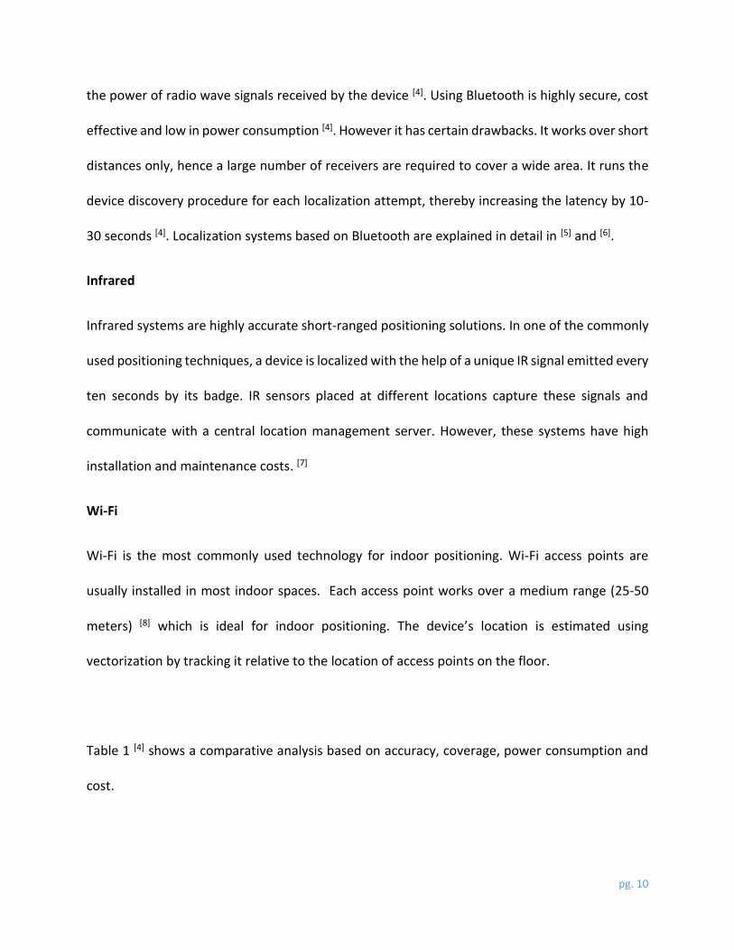
Qualcomm Indoor Location Technology
Qualcomm’s indoor location technology (IZat) is a chip-based platform that facilitates delivery of
location-aware networks. Qualcomm Atheros’ 802.11ac and 802.11n access point solutions
include advanced Wi-Fi based calculations to localize devices indoors with an accuracy of 5
meters. These access points, in conjunction with a server component they interact with, form a
cohesive indoor positioning system. [9]
Figure 1 shows the different components in Qualcomm’s IZat system.
pg. 12
Figure 1: Qualcomm's IZat [9]
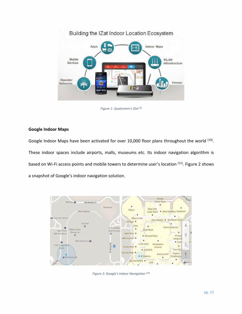
Google Indoor Maps
Google Indoor Maps have been activated for over 10,000 floor plans throughout the world [10].
These indoor spaces include airports, malls, museums etc. Its indoor navigation algorithm is
based on Wi-Fi access points and mobile towers to determine user’s location [11]. Figure 2 shows
a snapshot of Google’s indoor navigation solution.
Figure 2: Google's Indoor Navigation [10]

pg. 13
Place Lab – Intel Research
The Place Lab architecture, developed for research purposes, consists of three key elements as
shown in Figure 4: Radio beacons installed at various places indoors, Databases containing the
beacon location information and clients that estimate their location from this data. Place Lab
provides location based on known positions of the access points which are provided by a
database cached on the detecting device. Place Lab is entirely dependent on the availability of
beacon locations, without which it cannot estimate anything about the current location. [12]
Figure 3 shows Place Lab’s user interface, while Figure 4 gives an overview of its architecture.
Figure 3: Place Lab UI [13] Figure 4: Place Lab architecture [12]
NAVVIS
The NAVVIS positioning system works on a large database of images of indoor places and
generates a 3D model of that place. The user needs to take a picture of his surroundings and
NAVVIS compares it with the images in the database to compute the user’s current location and
orientation. It is also smart enough to analyze the picture provided by the user for any changes

pg. 14
in the indoor space and update its database accordingly. [14] Figure 5 shows NAVVIS’s user
interface in action.
InfSoft
InfSoft makes use of multiple wireless technologies – Wi-Fi, Bluetooth and GPS to localize an
object indoors. It further implements augmented reality to overlay the device’s camera view with
relevant navigational information as shown in Figure 6. [15]
Figure 6: InfSoft UI [15]
Figure 5: NAVVIS UI [14]

pg. 15
2.3. What sets us apart?
Similar to NAVVIS and InfSoft, our system leverages augmented reality to render relevant
information on the user interface. However unlike any of the existing systems, our solution
overlays points of interest on the live camera stream based on user’s context – while NAVVIS and
InfSoft just have arrows rendered on screen to help user navigation, our application has a wide
range of functionalities based on the user’s preferences (described in the following sections). It
provides a rich user experience by enhancing interactivity with virtual objects on screen. Another
differentiator is that our solution provides a generic framework that can be easily tailored and
applied to almost any indoor space.
3. Methodology
We decided to develop an Android application (Augmented Lab) to demonstrate the usefulness
of combining augmented reality with indoor positioning. We needed access to an existing indoor
positioning API to accurately determine the smartphone’s location and a 2D map of the indoor
space. As such, our application could accommodate any indoor positioning API. Our industrial
sponsor was Qualcomm Research Silicon Valley and we started working on this project hoping to
use their indoor positioning platform (IZat). However, due to licensing hurdles, we could not get
access to IZat and we had to simulate an indoor positioning API to serve our purpose.
The application development process was sub-divided into the following chronological stages:

pg. 16
3.1. Targeting a specific user scenario
We targeted a specific user scenario for this project. We got access to the CITRIS Invention lab in
the University of California Berkeley, where students work on 3D printers, laser cutting tools and
other such devices. To recognize frequently used devices in the lab and important use-cases that
are relevant to the users, we conducted some initial user interviews with the lab managers,
students and lab visitors. From these interviews, we identified two types of potential users –
students or faculty who use these devices and visitors who take a lab tour to check out different
devices and their demo products. Consequently, we determined four broad use-cases – learning
how to use the devices in the lab (apprentice mode), taking a tour to see cool demo products
(visitor mode), navigating to different devices in the room (navigation mode) and checking which
devices are currently being used (calendar mode).
3.2. Developing a mockup user interface
Based on the feedback from our interviewees, we designed a low fidelity prototype using
Balsamiq – a user interface generator that helps build simple interfaces without writing any code
to back them up. User tasks were simple – selecting one of the four modes based on his or her
preference and pointing the phone/tablet towards a particular device in the lab. The application
detects each device’s location relative to that of the user and the user interface primarily shows
relevant graphics and text overlaid on top of the camera view. The overlaid content depends on
the selected mode. In case of the apprentice mode, the user can go through an interactive step-
by-step guide explaining how to use that particular device. Figure 7 shows the apprentice mode
pg. 17
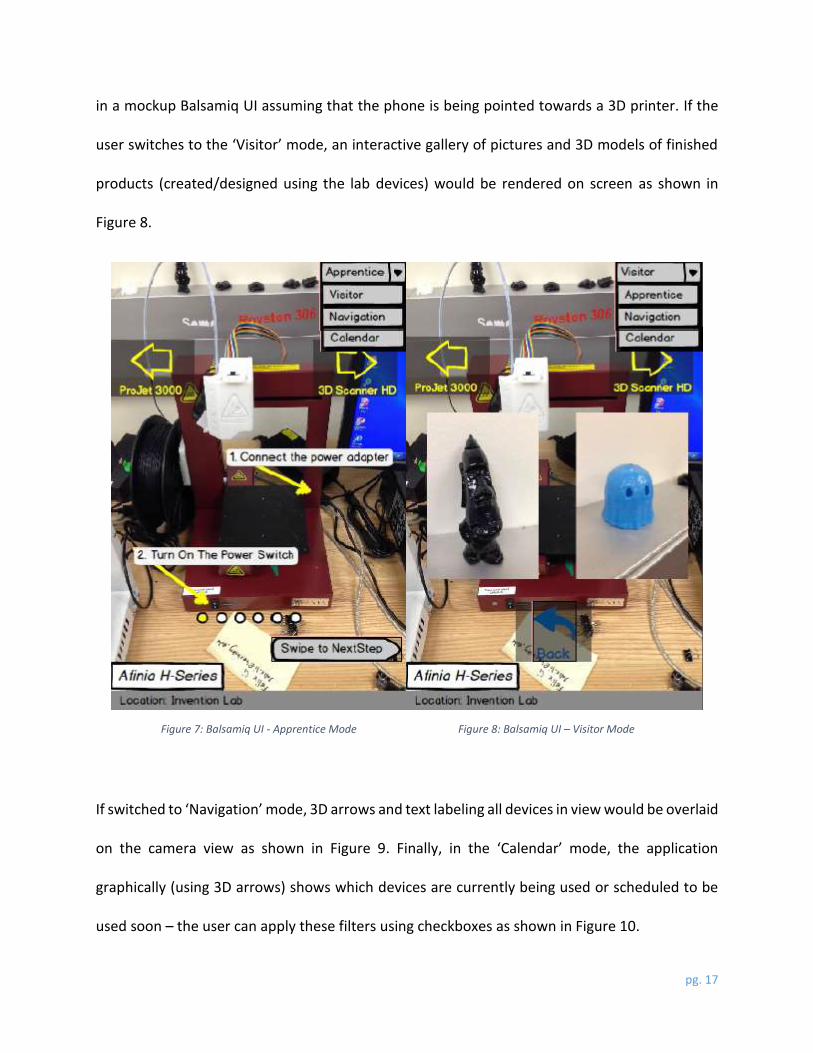
in a mockup Balsamiq UI assuming that the phone is being pointed towards a 3D printer. If the
user switches to the ‘Visitor’ mode, an interactive gallery of pictures and 3D models of finished
products (created/designed using the lab devices) would be rendered on screen as shown in
Figure 8.
Figure 7: Balsamiq UI - Apprentice Mode Figure 8: Balsamiq UI – Visitor Mode
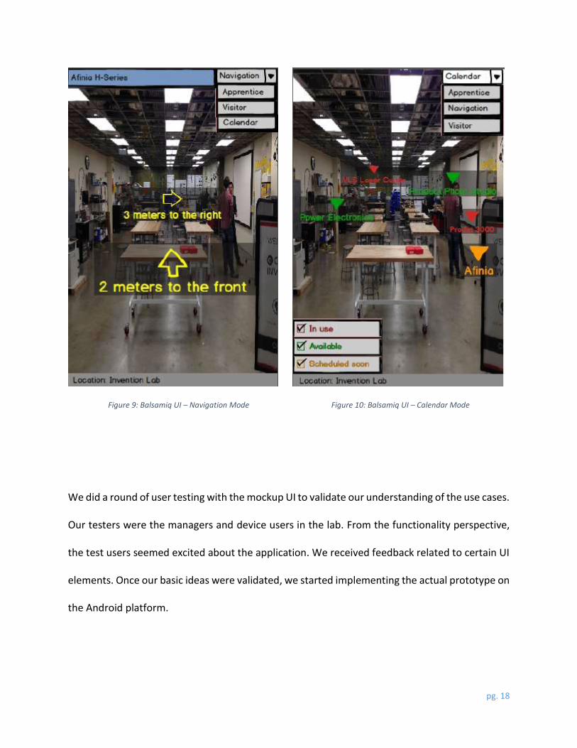
If switched to ‘Navigation’ mode, 3D arrows and text labeling all devices in view would be overlaid
on the camera view as shown in Figure 9. Finally, in the ‘Calendar’ mode, the application
graphically (using 3D arrows) shows which devices are currently being used or scheduled to be
used soon – the user can apply these filters using checkboxes as shown in Figure 10.
pg. 18
Figure 9: Balsamiq UI – Navigation Mode Figure 10: Balsamiq UI – Calendar Mode
We did a round of user testing with the mockup UI to validate our understanding of the use cases.
Our testers were the managers and device users in the lab. From the functionality perspective,
the test users seemed excited about the application. We received feedback related to certain UI
elements. Once our basic ideas were validated, we started implementing the actual prototype on
the Android platform.

pg. 19
3.3. Developing an interactive prototype
Figure 11 shows that the modules in our application are broadly categorized into three sections
– the “Position + Orientation” section roughly determines the phone’s location and orientation,
the “Augmented reality” section renders relevant graphics on top of the camera view and the
“User Interactivity” section gels everything together and provides a rich interactive experience
with the help of gesture control. Rest of this section discusses each module in detail (link to our
source code: https://github.com/axzhong3/ARVisionMap)
As mentioned before, we could not get access to Qualcomm’s proprietary indoor location API. So
we created a simulated location API to work-around this issue. As shown in Figure 12, we
designed a website (http://augmentedrealitymap.appspot.com/) that highlights a particular
location on Google Maps. The initial location is that of a point in the CITRIS Invention lab in the
Figure 11: Modules in our application

pg. 20
University of California, Berkeley and we can manually move it in all four directions. Different
devices in the lab are marked on this map. The website maintains the current coordinates in the
JSON (JavaScript Object Notation), a popular data interchange format. Meanwhile, our
application continuously (after every 10 seconds) fetches the coordinates (latitude and
longitude) from this website using an HTTP Client in Android. We create a JSON Object that parses
the coordinate values from our website. A separate thread handles this location fetching
mechanism so that the main UI thread can handle the other functionalities in the application.
Figure 12: Our website for the simulated Location API

pg. 21
Once the phone’s location in an indoor space is determined using the simulated API, we compute
its orientation relative to the magnetic north using its accelerometer and magnetometer
(orientation sensors). Android provides an easy API to read sensor events and obtain the azimuth,
roll and pitch values. Using the location API and orientation values, we can determine which
device in the lab lies in front of the user’s phone/tablet.
Like any augmented reality system, the base view in our application is the camera view and
graphics/text are overlaid on top of it. Initially, we used Android’s camera API to interact with the
camera hardware of the phone/tablet and access the live image stream. However, we switched
over to the camera API provided by OpenCV (Open Source Computer Vision Library), a cross-
platform library that deals with real-time image processing. We envisage using object detection
techniques in future to make localization even more robust, hence we decided to work with
OpenCV’s camera API. The image returned by this API forms the lowest layer in our application.
We used OpenGL ES 2.0 to render graphics in Android. OpenGL is a graphics library to render
graphic 3D shapes and textures. Figure 13 [16] gives an overview of the OpenGL rendering pipeline.
We implemented each of the following rendering stages for all objects to be shown on screen.
Figure 13: OpenGL rendering pipeline [16]

pg. 22
Shaders are essentially programs which define what to render and how to render. Vertex shaders
define the transformations for all vertices in any 2D/3D shape. They are also used to map custom
textures on 3D objects. Fragment shaders are used to define the color value of each pixel. We
have implemented custom vertex and fragment shaders to render 3D shapes. These shaders are
generic, so we reused them for drawing multiple objects dynamically on the screen depending
on their projection and view matrices. The projection and view matrices for different objects to
be rendered are determined based on the location information provided by the location API and
orientation sensor readings. Once the position, color and other attributes of all graphical shapes
are determined, they are drawn on top of the live camera stream.
One challenge that we faced here was flexibly writing text on top of the OpenGL layer. OpenGL
does not really have an easy method to render text on screen. We solved this problem by using
Android’s FrameLayout and stacking TextViews on top of the OpenGL layer which is in turn
stacked over the camera view.
As mentioned before, the content that goes over the camera view depends on the mode selected
by the user. When the application is launched, the default mode is the ‘World’ mode which
displays textures of captions for different devices in the lab – locations of these devices in the
object space is directly mapped with their corresponding locations on our map in Figure 12. The
application showcases a drop-down menu that contains ‘World’ mode, ‘Navigation’ mode and
‘Calendar’ mode as shown in Figure 14.

pg. 23
Figure 14: Interactive Prototype – Basic mode selection
To enhance user interactivity, we implemented a mechanism that allows the user to select a
device by a long press on the corresponding caption. The long press is handled using Android’s
Gesture API and the selected device is determined by approximating the camera’s field of view
angle and the phone’s current orientation. In the ‘World’ mode, a long press on a caption results
in a dialog box that asks the user to select either ‘Visitor’ mode or the ‘Apprentice’ mode as
shown in Figure 15.
Figure 15: Interactive Prototype – Device selection in ‘World’ mode

pg. 24
The ‘Visitor’ mode for a particular device is a gallery of 3D graphical models of products that were
designed or created using that device. This mode basically gives an idea to the user of what
exactly s/he can do with that device. The graphical models are rendered using OpenGL shaders
as described above. The user can rotate each model to view it from different angles as well as
pinch-zoom it. This user interactivity has been implemented using Android’s Gesture and Touch
APIs. Figure 16 shows a T-Rex model created using the Afinia 3D printer.
The ‘Apprentice’ mode has been implemented using Android’s ViewPager. ViewPager is basically
a group of “swipe-able” pages. In this mode, each instruction in the “How-to-use” guide is
displayed on a ViewPager page. Figure 17 shows one of the instructions for the laser cutting tool.
Figure 16: Interactive Prototype – Visitor mode

pg. 25
Figure 17: Interactive Prototype – Apprentice Mode
The user can select the ‘Navigation’ mode from the main drop-down menu (Figure 14) to get
graphical navigational information on the screen. The required device can be selected using
another drop-down menu that appears specifically for this mode as shown in Figure 18.
Figure 18: Interactive Prototype – Device Selection in the Navigation mode

pg. 26
Once the user selects the device that s/he is looking for, a flat graphical arrow that points towards
the selected device is rendered on the screen. This arrow is rendered using OpenGL vertex and
fragment shaders. Figure 19 shows ‘Navigation’ mode for the Afinia 3D printer.
Figure 19: Interactive Prototype – Navigation Mode
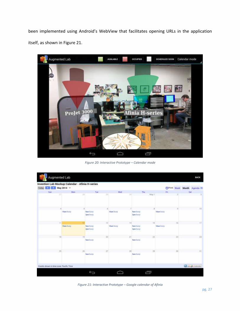
Finally, the user can select the ‘Calendar’ mode from the main drop-down menu to check the
current availability or the Google calendar of a particular device. As you can see in Figure 20, the
user can select one or more of the three checkboxes to see which devices are currently available,
occupied or scheduled to be used soon. The devices are marked with 3D arrows (again rendered
using OpenGL shaders) of different colors depending on their status. The user can also do a ‘long
press’ on the caption of a device to see its Google calendar and book a slot accordingly. This has
pg. 27
been implemented using Android’s WebView that facilitates opening URLs in the application
itself, as shown in Figure 21.
Figure 20: Interactive Prototype – Calendar mode
Figure 21: Interactive Prototype – Google calendar of Afinia

pg. 28
4. Results: User Study
We conducted another user study, this time for our interactive prototype. Ten users in the CITRIS
Invention lab, UC Berkeley were randomly selected. The study was conducted on the Afinia 3D
printer in the lab. The sample set consisted of lab administrators, undergraduate and graduate
students who had some experience of working on Afinia. They were asked to try out the different
functionalities in our application and then answer some questions related to usability. Some of
the highlights are as follows:
Test users were asked to rank different functionalities based on their practicality and usefulness.
The ‘Apprentice’ and ‘Calendar’ modes turned out to be the most popular features. Figure 22
shows an average ranking for each feature (1 being the highest rank).
32.8
3
1.8
2.42.2
0
0.5
1
1.5
2
2.5
3
3.5
Interactivity toexplore details
(World)
DeviceNavigation
(Navigation)
Gallery of 3Dmodels(Visitor)
Flowchart(Apprentice)
Device statuslookup
(Calendar)
Access Googlecalendars(Calendar)
Ran
k
Features
Average Feature Ranking
Figure 22: User Study: Average Feature Ranks
pg. 29
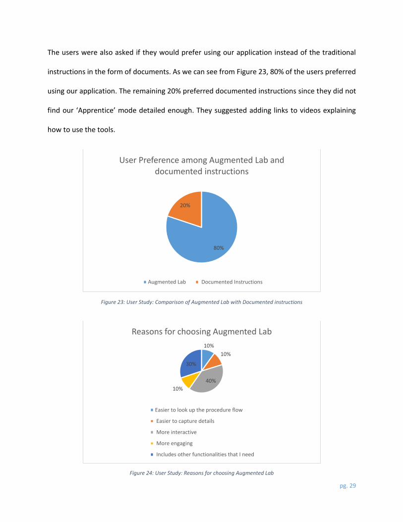
The users were also asked if they would prefer using our application instead of the traditional
instructions in the form of documents. As we can see from Figure 23, 80% of the users preferred
using our application. The remaining 20% preferred documented instructions since they did not
find our ‘Apprentice’ mode detailed enough. They suggested adding links to videos explaining
how to use the tools.
80%
20%
User Preference among Augmented Lab and documented instructions
Augmented Lab Documented Instructions
10%
10%
40%
10%
30%
Reasons for choosing Augmented Lab
Easier to look up the procedure flow
Easier to capture details
More interactive
More engaging
Includes other functionalities that I need
Figure 23: User Study: Comparison of Augmented Lab with Documented instructions
Figure 24: User Study: Reasons for choosing Augmented Lab

pg. 30
The users were also asked for improvement suggestions or general feedback with respect to
functionality and usability of the application. Some of them observed that the device captions on
the camera view were kind of shaky and should be stabilized. A couple of users suggested that
we should also focus on smaller tools (like a screw driver) in the ‘Navigation’ mode since they are
harder to locate as compared to larger ones (like the 3D printer). Some users also recommended
maintaining a checklist in the ‘Apprentice’ mode so that experienced users need not have to go
through the entire flowchart.
Overall, the users were quite excited by the visual appeal and varied functionalities in our
application and thought that it provided a rich interactive user experience.
5. Conclusion
Future work could include replacing our simulated location API with Qualcomm’s indoor
positioning system (IZat). We could also implement computer vision techniques to detect objects
that are visible in the camera view. At this point, localization in our approach is entirely based on
the location API and orientation sensor readings. Integrating object detection in the current
approach would make the localization extremely robust, giving an inch-level accuracy. As of now,
once the device is detected (based on location and orientation) the ‘Apprentice’ mode shows
static images that explains how to use that device. If we are able to implement a highly accurate
object detection algorithm, then we can get rid of the static images in ‘Apprentice’ mode and
render text and 3D arrows accurately pointing to different parts of the device.

pg. 31
We have identified two approaches for object detection in this context. In the first approach, we
could add markers on different devices in the lab and detect them in the images taken by the
camera. A marker is basically an indicator, with a distinct pattern (color and/or shape) that is easy
to detect in an image. An advantage of this approach is that we do not need to implement
complex machine learning algorithms to train images since we only need to search for known
distinct markers. However, this approach is not really flexible – in case of a huge indoor space
with a large number of objects, it is not feasible to add markers on each object. Also, having a lot
of markers beats the purpose since the detection won’t be trivial anymore. Another approach
would be implementing a full-fledged object detection using OpenCV based Haar training. Haar
training is used to train sample images, which is a necessary task for any machine learning based
object detection task. The detection accuracy depends on how well the system was trained based
on a large set of sample images. This approach is complex and the training is extremely time-
consuming. However, it is much more scalable and flexible as compared to using markers.
To summarize, there is a strong untapped potential in augmented reality in the context of indoor
navigation and we have attempted to demonstrate this to a certain extent in our application. We
explored four representative modes (‘Apprentice’, ‘Navigation’, ‘Visitor’, ‘Calendar’), each of
which could be extended based on different user scenarios. The strength of our approach is that
it is completely generic and can be tuned to work with any indoor space such as malls, hospitals,
museums, airports etc.

pg. 32
References
1. Hui Liu, Darabi, H., Banerjee, P., Jing Liu. (Nov. 2007). Survey of Wireless Indoor Positioning
Techniques and Systems, IEEE Transactions, vol.37, no.6, pp.1067, 1080.
2. Author unknown. (Date unknown). Augmented Reality To Museum Learning. [Online].
Available: http://www.pocket-lint.com/news/125475-the-british-museum-and-
samsung-bring-augmented-reality-to-museum-learning
3. Author unknown. (Date unknown). Bluetooth Wavelength & Frequency. [Online].
Available: http://www.ehow.com/info_8722444_bluetooth-wavelength-frequency.html
4. Zahid Farid, Rosdiadee Nordin & Mahamod Ismail. (Date unknown). Recent Advances in
Wireless Indoor Localization Techniques and System, Journal of Computer Networks &
Communications, vol. 2013.
5. F. Subhan, H. Hasbullah, A. Rozyyev, and S. T. Bakhsh, “Indoor positioning in Bluetooth
networks using fingerprinting and lateration approach,” inProceedings of the
International Conference on Information Science and Applications (ICISA ’11), April 2011.
6. H. J. Perez Iglesias, V. Barral, and C. J. Escudero, “Indoor person localization system
through RSSI Bluetooth fingerprinting,” in Proceedings of the 19th International
Conference on Systems, Signals and Image Processing (IWSSIP ’12), pp. 40–43, April 2012.
7. Manh H V. Le, Dimitris Saragas. (Oct. 2009). Indoor Navigation System for Handheld
Devices. Worcester Polytechnic Institute Electronic Project Collection, E-project-102209-
164024.
8. Evennou, F., Marx, F. (2006). Advanced integration of wifi and inertial navigation systems
for indoor mobile positioning. EURASIP J. Appl. Signal Process. 2006, 164-164

pg. 33
9. Author unknown. (Date unknown). Qualcomm Indoor Location. [Online]. Available:
http://www.qualcomm.com/connect/analyst-relations/briefing-center/indoor-location
10. Author unknown. (Date unknown). Indoor Maps availability. [Online]. Available:
https://support.google.com/gmm/answer/1685827?hl=en
11. Author unknown. (Date unknown). Google Indoor Maps. [Online]. Available:
http://www.smh.com.au/digital-life/smartphone-apps/inside-out-google-launches-
indoor-maps-20130312-2fxz2.html
12. LaMarca A, Chawathe Y, Consolvo S, Hightower J, Smith I, Scott J, Sohn T, Howard J,
Hughes J, Potter F, Tabert J, Powledge P, Borriello G, Schilit B. (May 2005). Place lab:
device positioning using radio beacons in the wild. In: Proceedings of the third
international conference on pervasive computing.
13. Author unknown. (Date unknown). The Augmented Blog. [Online]. Available:
http://augmentedblog.wordpress.com/tag/indoor/
14. Author unknown. (Date unknown). Improving positioning indoors with imaging data.
[Online]. Available: http://phys.org/news/2012-09-positioning-indoors-imaging.html#jCp
15. Author unknown. (Date unknown). InfSoft indoor navigation. [Online]. Available:
http://www.infsoft.com/indoor-navigation/
16. Kevin Brothaler, “Defining Vertices and Shaders” in OpenGL ES 2 for Android: A Quick-
Start Guide, Dallas, Texas: The Pragmatic Bookshelf, 2013.


![ARIANNA: pAth Recognition for Indoor Assisted NavigatioN with Augmented perception · 2019. 11. 12. · possible navigation errors. In [6], vibrational feed-back is given by a special](https://img.dokumen.tips/doc/110x75/60fbfa413a1e3443414d9a33/arianna-path-recognition-for-indoor-assisted-navigation-with-augmented-perception.jpg)