Embed Size (px)
Citation preview
[1]
IMPROVING SYSTEM RELIABILITY WITH SYNJET COOLING
Central Texas Electronics Association Electronics
Design & Manufacturing Symposium
February 22, 2011
Markus Schwickert

[2]
SynJet® (Synthetic Jet) Operating Principle
• Rapid-fire pulses of turbulent air produced by an
oscillating diaphragm, typically 30 to 200
pulses/second
• Each pulse is well defined high momentum air
• High velocity air sheds vortices breaks up boundary
layers
Oscillating Diaphragm
Entrained Air
Synthetic Jet
Vortices Cavity
Nozzle
Entrained Air
• Pulsating flow increases mixing, that turbulence
increases heat transfer
• SynJet flow is synthesized entirely from the
ambient air
• A secondary flow is entrained from the
surrounding air due to the primary high
momentum jet
Heatsink
Flash Video Link: http://nuventix.com/synjet_flash_demo/

[3]
SynJet® Coolers
SynJet® Coolers are paired with different heatsinks
to provide full thermal solutions.
ZFlow 50 ZFlow 65 ZFlow 75 ZFlow 100 XFlow 30

[4]
SynJet® Cooler and Heatsink Solutions
ZFlow 50
MR16
Style
Downlights
Downlights
Removable
Designs
Spotlights
Linear lights
Par Style
500 1000 1500 2000 2500 3000
Approximate Lumens Cooled
ZFlow 65
Spotlight
21W
ZFlow 75
Spotlight
31W
ZFlow 75
Spotlight
34W
ZFlow 75
Spotlight
38W
ZFlow 65
Par20ZFlow 65
Par25ZFlow 65
Par30
XFlow 30
ZFlow 65
CoolTwist
ZFlow 100
Downlight
120
ZFlow
100
Downligh
t 140
[5]
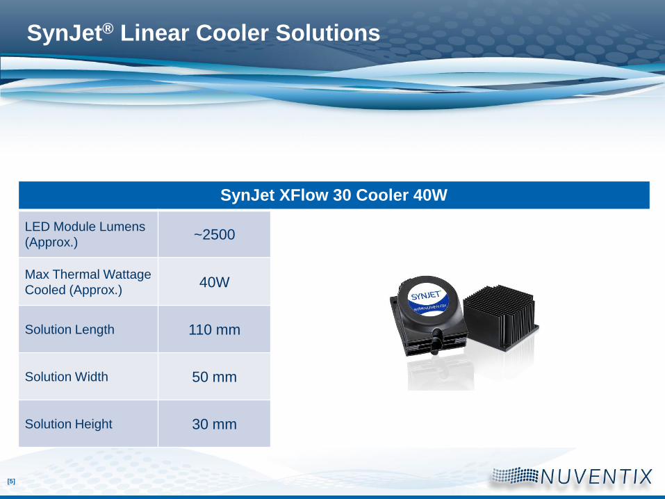
SynJet XFlow 30 Cooler 40W
LED Module Lumens
(Approx.)~2500
Max Thermal Wattage
Cooled (Approx.)40W
Solution Length 110 mm
Solution Width 50 mm
Solution Height 30 mm
SynJet® Linear Cooler Solutions
[6]
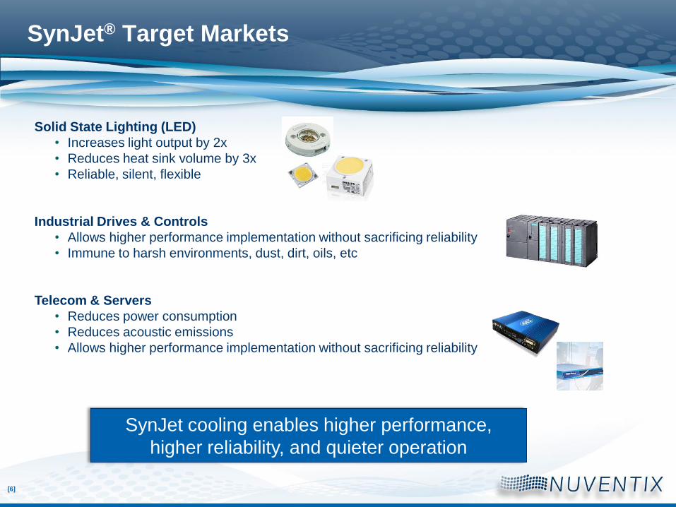
SynJet® Target Markets
Solid State Lighting (LED)
• Increases light output by 2x
• Reduces heat sink volume by 3x
• Reliable, silent, flexible
Industrial Drives & Controls
• Allows higher performance implementation without sacrificing reliability
• Immune to harsh environments, dust, dirt, oils, etc
Telecom & Servers
• Reduces power consumption
• Reduces acoustic emissions
• Allows higher performance implementation without sacrificing reliability
SynJet cooling enables higher performance,
higher reliability, and quieter operation
[7]
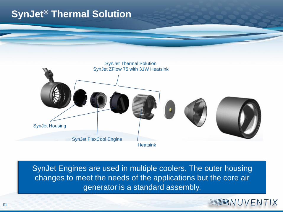
SynJet® Thermal Solution
SynJet FlexCool Engine
SynJet Thermal Solution
SynJet ZFlow 75 with 31W Heatsink
Heatsink
SynJet Housing
SynJet Engines are used in multiple coolers. The outer housing
changes to meet the needs of the applications but the core air
generator is a standard assembly.

[8]
[9]
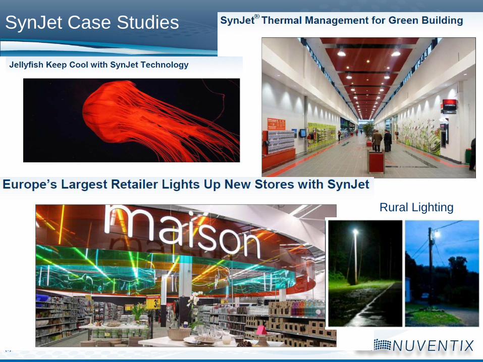
Rural Lighting
SynJet Case Studies
[10]
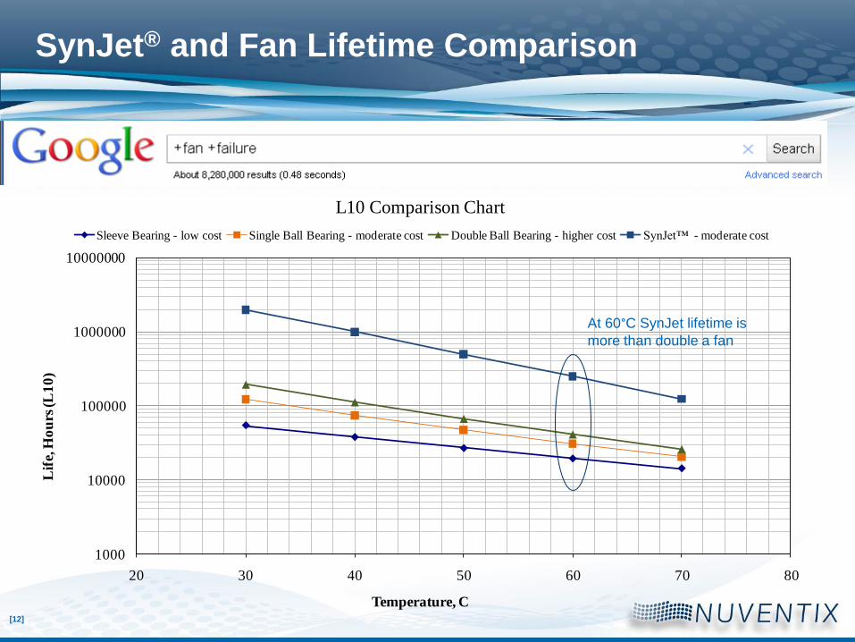
Lifetime Definition: L10
The point of time at which the cumulative failures of a product reach 10%
and 90% remain functioning as intended under stated conditions.
[11]
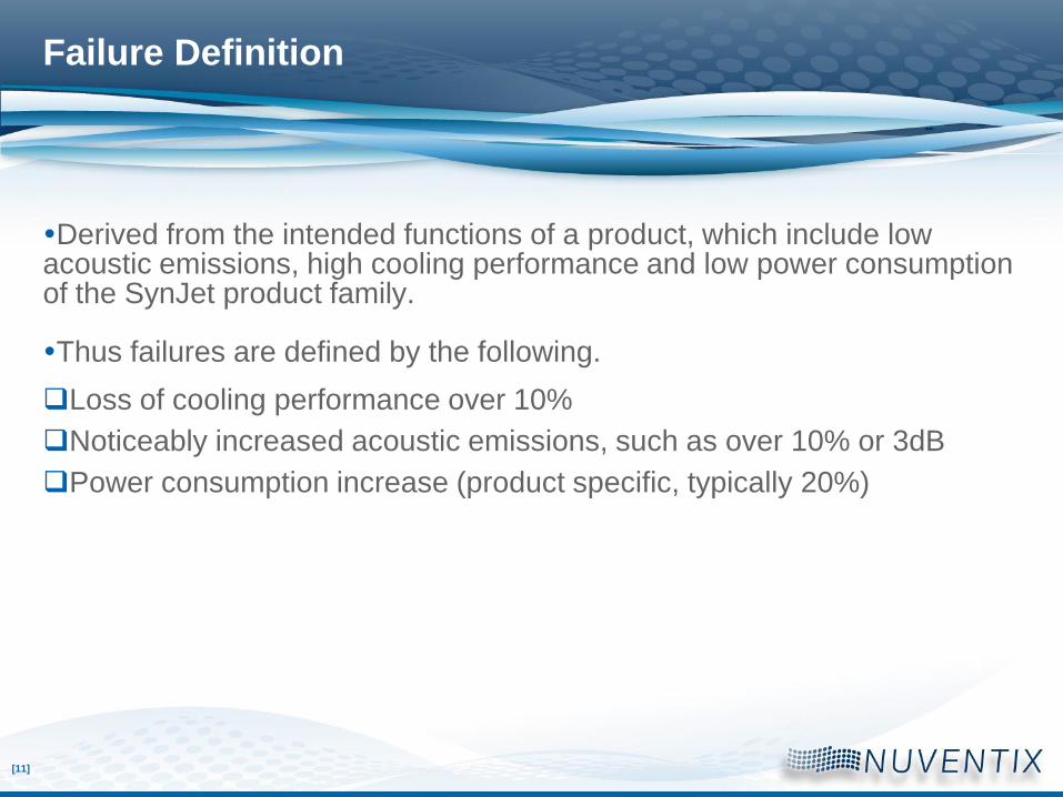
Failure Definition
Derived from the intended functions of a product, which include low acoustic emissions, high cooling performance and low power consumption of the SynJet product family.
Thus failures are defined by the following.
Loss of cooling performance over 10%
Noticeably increased acoustic emissions, such as over 10% or 3dB
Power consumption increase (product specific, typically 20%)
[12]
1000
10000
100000
1000000
10000000
20 30 40 50 60 70 80
Lif
e, H
ou
rs (L
10
)
Temperature, C
L10 Comparison Chart
Sleeve Bearing - low cost Single Ball Bearing - moderate cost Double Ball Bearing - higher cost SynJet™ - moderate cost
SynJet® and Fan Lifetime Comparison
At 60°C SynJet lifetime is
more than double a fan
[13]
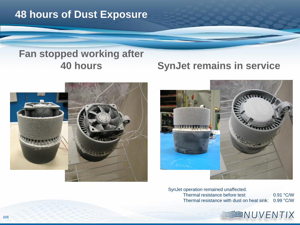
48 hours of Dust Exposure
Fan stopped working after
40 hours SynJet remains in service
SynJet operation remained unaffected.
Thermal resistance before test: 0.91 °C/W
Thermal resistance with dust on heat sink: 0.99 °C/W
[14]
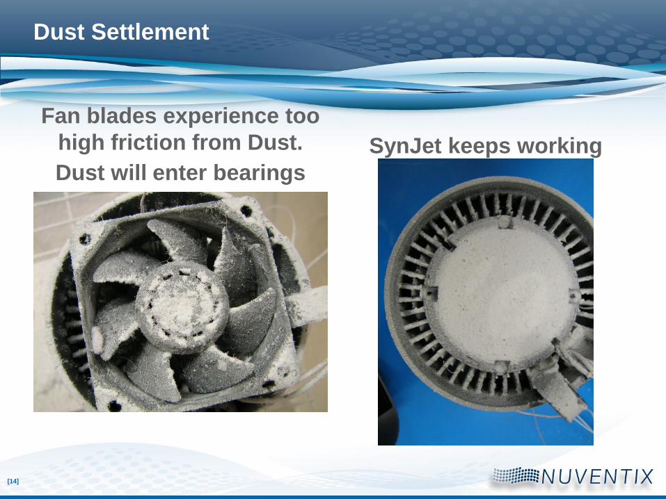
Dust Settlement
Fan blades experience too
high friction from Dust.
Dust will enter bearings
SynJet keeps working
[15]
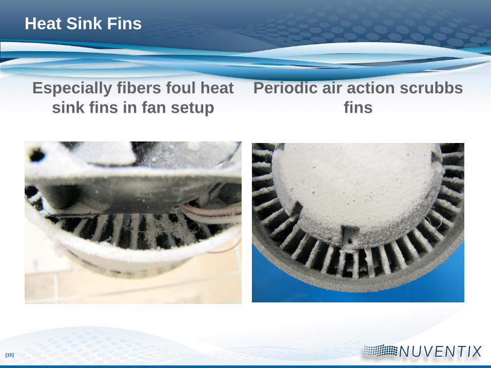
Heat Sink Fins
Especially fibers foul heat
sink fins in fan setup
Periodic air action scrubbs
fins
[16]
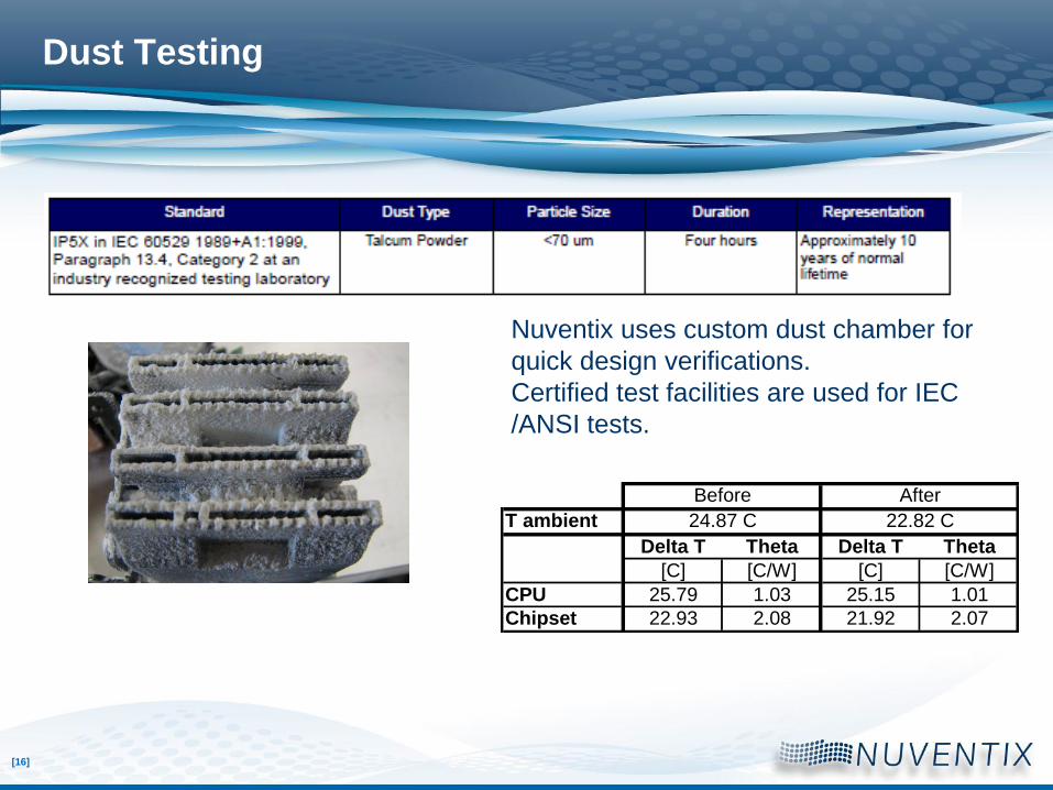
Dust Testing
T ambient
Delta T Theta Delta T Theta
[C] [C/W] [C] [C/W]
CPU 25.79 1.03 25.15 1.01
Chipset 22.93 2.08 21.92 2.07
AfterBefore
24.87 C 22.82 C
Nuventix uses custom dust chamber for
quick design verifications.
Certified test facilities are used for IEC
/ANSI tests.
[17]
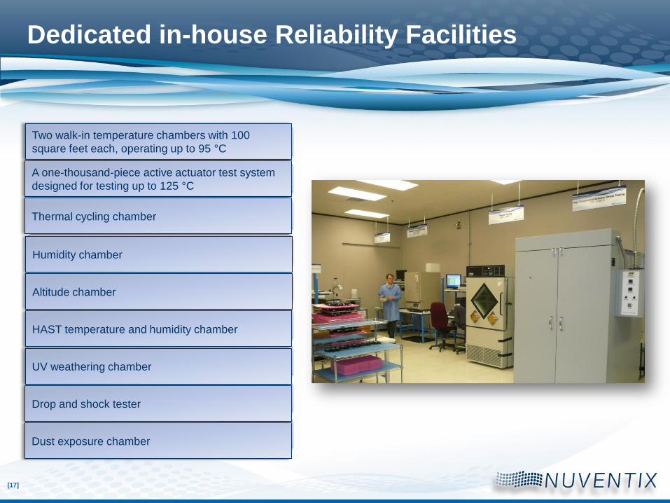
Dedicated in-house Reliability Facilities
Two walk-in temperature chambers with 100 square feet each, operating up to 95 °C
A one-thousand-piece active actuator test system designed for testing up to 125 °C.
Thermal cycling chamber
Humidity chamber
Altitude chamber
HAST temperature and humidity chamber
UV weathering chamber
Drop and shock tester
Dust exposure chamber
Two walk-in temperature chambers with 100
square feet each, operating up to 95 °C
A one-thousand-piece active actuator test system
designed for testing up to 125 °C
Thermal cycling chamber
Humidity chamber
Altitude chamber
HAST temperature and humidity chamber
UV weathering chamber
Drop and shock tester
Dust exposure chamber

[18]
Temperature and Humidity
Examples of SynJet test conditions are:
Operational at 70 °C / 90 % r.h. for 32 days [pass]
Non-operational and operational at 85 °C / 85 % r.h. for 3,300 hours [pass]
Espec LHU-113 Espec ETH-33
[19]
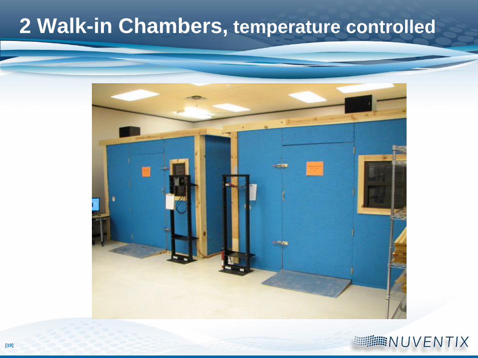
2 Walk-in Chambers, temperature controlled
[20] Nuventix Confidential
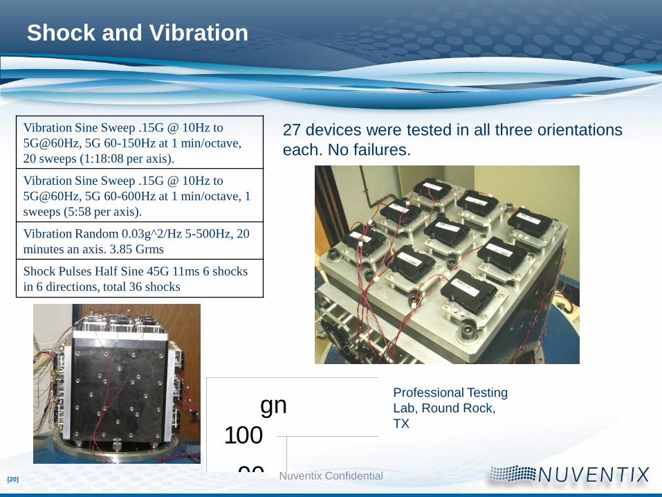
Shock and Vibration
Vibration Sine Sweep .15G @ 10Hz to
5G@60Hz, 5G 60-150Hz at 1 min/octave,
20 sweeps (1:18:08 per axis).
Vibration Sine Sweep .15G @ 10Hz to
5G@60Hz, 5G 60-600Hz at 1 min/octave, 1
sweeps (5:58 per axis).
Vibration Random 0.03g^2/Hz 5-500Hz, 20
minutes an axis. 3.85 Grms
Shock Pulses Half Sine 45G 11ms 6 shocks
in 6 directions, total 36 shocks
27 devices were tested in all three orientations
each. No failures.
Professional Testing
Lab, Round Rock,
TX
profile(t)
R1 Response:
Peak = 44.519 gn
C1 Control:
Peak = 44.960 gn
27-15 -12 -8 -4 0 4 8 12 16 20 24
100
-100
-90
-75
-60
-45
-30
-15
0
15
30
45
60
75
90
Time (Milliseconds)
gn
[21]
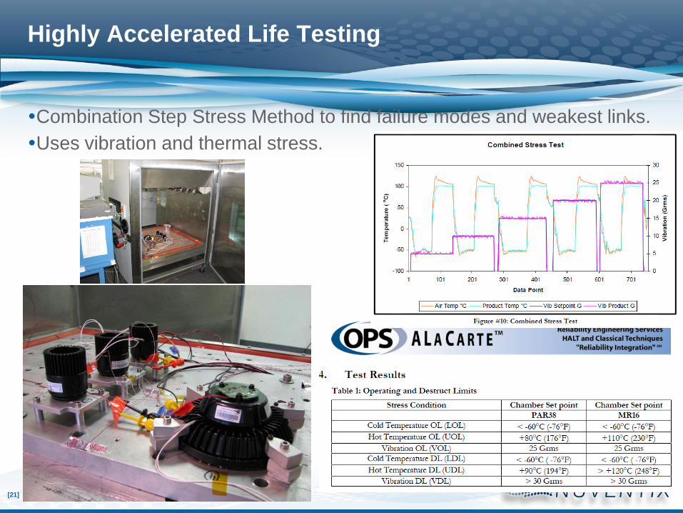
Highly Accelerated Life Testing
Combination Step Stress Method to find failure modes and weakest links.
Uses vibration and thermal stress.
[22]
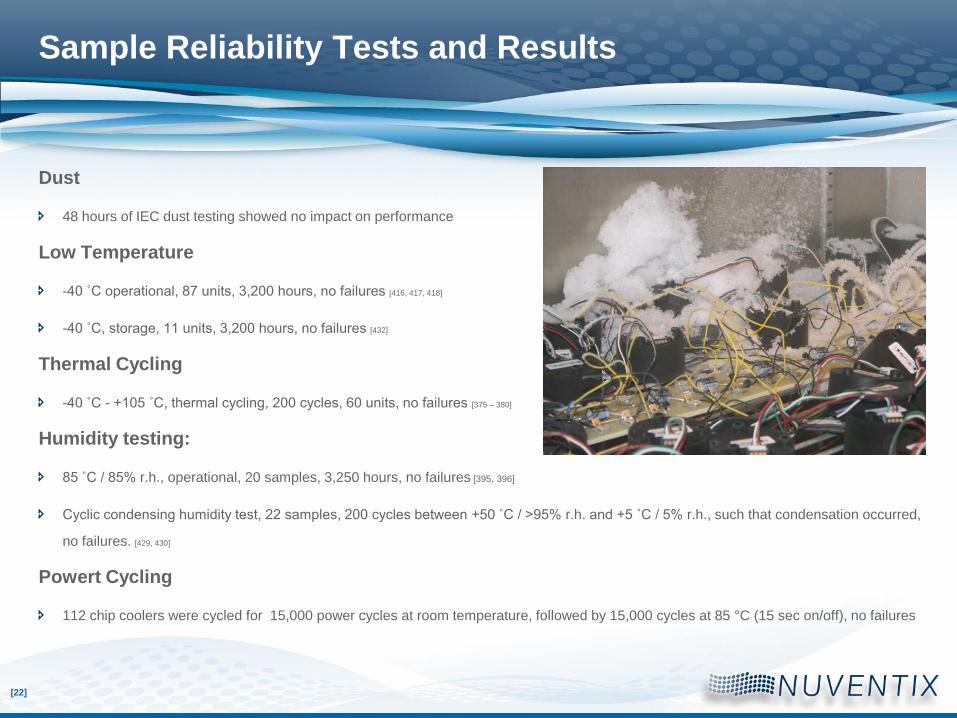
Sample Reliability Tests and Results
Dust
48 hours of IEC dust testing showed no impact on performance
Low Temperature
-40 ˚C operational, 87 units, 3,200 hours, no failures [416, 417, 418]
-40 ˚C, storage, 11 units, 3,200 hours, no failures [432]
Thermal Cycling
-40 ˚C - +105 ˚C, thermal cycling, 200 cycles, 60 units, no failures [375 – 380]
Humidity testing:
85 ˚C / 85% r.h., operational, 20 samples, 3,250 hours, no failures [395, 396]
Cyclic condensing humidity test, 22 samples, 200 cycles between +50 ˚C / >95% r.h. and +5 ˚C / 5% r.h., such that condensation occurred,
no failures. [429, 430]
Powert Cycling
112 chip coolers were cycled for 15,000 power cycles at room temperature, followed by 15,000 cycles at 85 °C (15 sec on/off), no failures

[23]
Sample Reliability Tests and Results, continued
Lifetime
540 samples at 105 °C (brief periods of 95 °C) ambient operating for 3,300
hours, no failures (establishes a minimum of 100k hours of L10 at 85 °C with
>90% confidence) [393, 394, 409, 410]. Note: 75 units continued testing in operation at 85 C ,
no planned end date (ca. 2000 hours as of now).
Cyclic Ice/Freeze Test:
21 samples, 100 cycles between +25 ˚C / 95% r.h. and –10 ˚C / u.c.r.h. such
that units freeze in humidity and powering units on after 20 minutes of
freezing, no failures. [437]
Shock and vibration testing: [387 – 392]
Bump Test: 1,000 shocks, half sine wave, 25 G, 10 ms, each of 6 directions
5 to 150 Hz sine sweeping, 2 G, 5 sweeps each of 3 axes
20 minute dwell, 5G at max resonance, each of 3 axes
Random vibration, 2.2 grms, 20 minutes each of 3 axes
No failures.
HAST, 123 C, 96% r.h., 2 atm.
3 FlexCool40 units tested for 60 hours (non-operational), pass

[24]
Field Reliability Data
8,000 SynJets operating in one case since 8/25/2010
4,355 calendar hours under use conditions
Lifetime prediction L10 > 255k hours and counting

[25]
Reliability Block Diagram
Hot Component Other
b c
= a + b + c
One can further split the diagram into the parts of the components etc.
Cooling Solution
a
System Failure Rate:

[26]
Reliability Block Diagram, redundant components
Cooling Solution
Hot component Other
b c
= 1/(1/ a + 1/ a)+ b + c
= ½ a + b + c
Adding a component to the system usually lowers system reliability,
Cooling Solution
a
a

[27]
Effect of Adding Cooling Components to a System
Hot Component Other
b c
= a + b + c
Cooling Solution
a
System life time is always
Limited by the shortest life
time of any critical
component
[28]
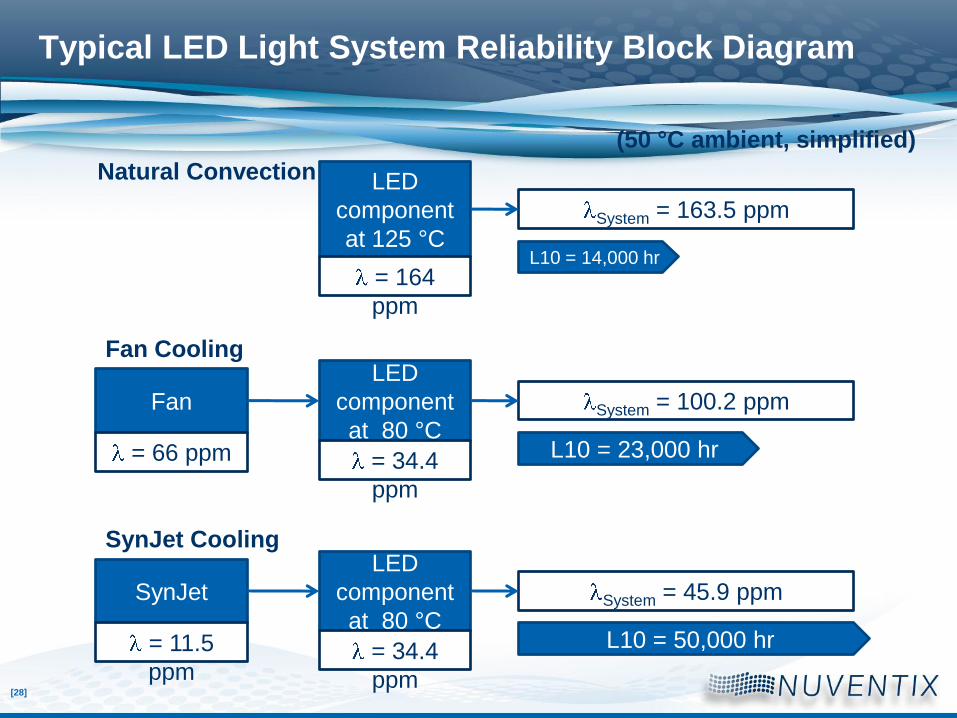
Typical LED Light System Reliability Block Diagram
(50 °C ambient, simplified)
SynJet Cooling
SynJet
= 11.5
ppm
LED
component
at 80 °C
= 34.4
ppm
System = 45.9 ppm
LED
component
at 125 °C
= 164
ppm
Natural Convection
System = 163.5 ppm
L10 = 14,000 hr
Fan Cooling
Fan
= 66 ppm
LED
component
at 80 °C
= 34.4
ppm
System = 100.2 ppm
L10 = 23,000 hr
L10 = 50,000 hr