Embed Size (px)
Citation preview
IMPROVING KERNEL PERFORMANCE FOR NETWORK SNIFFING
A THESIS SUBMITTED TOTHE GRADUATE SCHOOL OF NATURAL AND APPLIED SCIENCES
OFTHE MIDDLE EAST TECHNICAL UNIVERSITY
BY
MEHMET ERSAN TOPALOGLU
IN PARTIAL FULFILLMENT OF THE REQUIREMENTS FOR THE DEGREE OF
MASTER OF SCIENCE
IN
THE DEPARTMENT OF COMPUTER ENGINEERING
SEPTEMBER 2003

Approval of the Graduate School of Natural and Applied Sciences.
PROF. DR. CANAN OZGENDirector
I certify that this thesis satisfies all the requirements as a thesis for the degreeof Master of Science.
PROF. DR. AYSE KIPERHead of Department
This is to certify that we have read this thesis and that in our opinion it is fullyadequate, in scope and quality, as a thesis for the degree of Master of Science.
DR. CEVAT SENERSupervisor
Examining Committee Members
ASST. PROF. DR. IBRAHIM KORPEOGLU
DR. ATILLA OZGIT
DR. ONUR TOLGA SEHITOGLU
DR. CEVAT SENER
Y. MUH. BURAK DAYIOGLU

ABSTRACT
IMPROVING KERNEL PERFORMANCE FOR NETWORK SNIFFING
TOPALOGLU, MEHMET ERSAN
MSc, Department of Computer Engineering
Supervisor: DR. CEVAT SENER
SEPTEMBER 2003, 76 pages
Sniffing is computer-network equivalent of telephone tapping. A Sniffer is simply
any software tool used for sniffing. Needs of modern networks today are much more
than a sniffer can meet, because of high network traffic and load.
Some efforts are shown to overcome this problem. Although successful approaches
exist, problem is not completely solved. Efforts mainly includes producing faster
hardware, modifying NICs (Network Interface Card), modifying kernel, or some
combinations of them. Most efforts are either costly or no know-how exists.
In this thesis, problem is attacked via modifying kernel and NIC with aim of transfer-
ring the data captured from the network to the application as fast as possible. Snort
[1], running on Linux, is used as a case study for performance comparison with the
original system. A significant amount of decrease in packet lost ratios is observed at
resultant system.
Keywords: sniffer, kernel modification, driver modification
iii

OZ
AG KOKLAMASI ICIN CEKIRDEK PERFORMANSININ ARTTIRILMASI
TOPALOGLU, MEHMET ERSAN
Master, Bilgisayar Muhendisligi Bolumu
Tez Yoneticisi: DR. CEVAT SENER
EYLUL 2003, 76 sayfa
Koklama, telefon dinlemenin bilgisayar-ag eslenigidir. Bir koklayıcı ise koklama icin
kullanılan herhangi bir yazılım aracıdır. Yuksek ag trafigi ve yuku sebebiyle modern
agların ihtiyacları koklayıcıların karsılayabileceginden cok daha fazladır.
Bu problemin ustesinden gelebilmek icin bazı cabalar gosterilmistir. Basarılı
yaklasımlar olsa da problem tamamen cozulememistir. Cabalar genellikle, daha hızlı
donanım kullanma, ag arayuz kartı suruculerinde degisiklik yapma, cekirdekte
degisiklik yapma ya da bunların kombinasyonlarını icermektedir. Cabaların cogu ya
pahalı ya da teknik bilgisi acıklanmamıs cabalardır.
Bu tezde, agdan yakalanan verinin uygulamaya mumkun oldugunca hızlı aktarılması
amacıyla, probleme cekirdekte ve ag arayuz kartı surucusunde degisiklik yaparak
saldırılmıstır.
iv

Asıl sistemle performans karsılastırması icin, vaka calısması olarak Linux uzerinde
calıstırılan Snort [1] kullanılmıstır. Paket kayıp oranlarında onemli miktarda dusus
gozlenmistir.
Anahtar Kelimeler: Koklayıcı, cekirdek degistirme, surucu degistirme
v

To My Family & Friends
vi

ACKNOWLEDGMENTS
I am grateful to my advisor Dr. Cevat Sener who guided me in my first academic
work. Prof. Dr. Fatos T. Yarman-Vural is one of the main reasons for me to be at
academic side.
It was Y. Muh. Burak Dayıoglu’s idea to work on this subject. He always guided
me in the thesis way and give wonderful ideas whenever i got stucked. Only being
thankful is never enough.
Alper Erdal provided CISCO equipments that i used during preliminary tests and
Ken Nelson let me use their software (understand c) that was useful when traveling
inside the Linux kernel.
Dr. Onur Tolga Sehitoglu supported the thesis with his great ideas. His comments
always made me continue my thesis.
My new home-mate Turan Yuksel provided latex style file and tried to find answers
to my endless latex questions.
Finally I would like to thank to Y. Muh. Barıs Sertkaya, Y. Muh. Irem Aktug, my
ex-homemates Serkan Toprak and Serkan Guvey, my family and other friends who
believed me and motivated me in my work.
vii
TABLE OF CONTENTS
ABSTRACT . . . . . . . . . . . . . . . . . . . . . . . . . . . . . . . . . . . . . . . iii
OZ . . . . . . . . . . . . . . . . . . . . . . . . . . . . . . . . . . . . . . . . . . . . . iv
DEDICATON . . . . . . . . . . . . . . . . . . . . . . . . . . . . . . . . . . . . . . vi
ACKNOWLEDGMENTS . . . . . . . . . . . . . . . . . . . . . . . . . . . . . . . . vii
TABLE OF CONTENTS . . . . . . . . . . . . . . . . . . . . . . . . . . . . . . . . viii
LIST OF TABLES . . . . . . . . . . . . . . . . . . . . . . . . . . . . . . . . . . . . xi
LIST OF FIGURES . . . . . . . . . . . . . . . . . . . . . . . . . . . . . . . . . . . . xiii
CHAPTER
1 INTRODUCTION . . . . . . . . . . . . . . . . . . . . . . . . . . . . . . . 1
2 SNIFFERS . . . . . . . . . . . . . . . . . . . . . . . . . . . . . . . . . . . 6
2.1 What is sniffing and how it works? . . . . . . . . . . . . . . . . 6
2.2 Application areas . . . . . . . . . . . . . . . . . . . . . . . . . . 7
2.2.1 Network Analysis and Debugging . . . . . . . . . . . 7
2.2.2 Intrusion Detection . . . . . . . . . . . . . . . . . . . . 8
2.2.2.1 Anomaly Detection . . . . . . . . . . . . . 9
2.2.2.2 Misuse Detection . . . . . . . . . . . . . . 10
2.2.2.3 Host-Based Intrusion Detection . . . . . . 11
2.2.2.4 Network Based Intrusion Detection . . . . 12
2.3 What to Sniff? . . . . . . . . . . . . . . . . . . . . . . . . . . . . 12
2.3.1 Authentication Information . . . . . . . . . . . . . . . 12
2.3.1.1 Telnet (Port 23) . . . . . . . . . . . . . . . . 13
2.3.1.2 FTP (Port 21) . . . . . . . . . . . . . . . . . 13
2.3.1.3 POP (Port 110) . . . . . . . . . . . . . . . . 13
2.3.1.4 IMAP (Port 143) . . . . . . . . . . . . . . . 13
2.3.1.5 NNTP (Port 119) . . . . . . . . . . . . . . . 13
viii

2.3.1.6 rexec (Port 512) . . . . . . . . . . . . . . . . 14
2.3.1.7 rlogin (Port 513) . . . . . . . . . . . . . . . 14
2.3.1.8 X11 (Port 6000+) . . . . . . . . . . . . . . . 14
2.3.1.9 NFS File Handles . . . . . . . . . . . . . . 15
2.3.1.10 Windows NT Authentication . . . . . . . . 15
2.3.2 Other Network Traffic . . . . . . . . . . . . . . . . . . 15
2.3.2.1 SMTP (Port 25) . . . . . . . . . . . . . . . . 16
2.3.2.2 HTTP (Port 80) . . . . . . . . . . . . . . . . 16
3 DESIGN . . . . . . . . . . . . . . . . . . . . . . . . . . . . . . . . . . . . 17
3.1 Networking in Linux Kernel . . . . . . . . . . . . . . . . . . . . 17
3.1.1 Network Devices . . . . . . . . . . . . . . . . . . . . . 18
3.1.2 Sockets and Protocols . . . . . . . . . . . . . . . . . . . 19
3.1.2.1 Protocols . . . . . . . . . . . . . . . . . . . 19
3.1.2.2 Sockets . . . . . . . . . . . . . . . . . . . . 20
3.1.3 Network Buffers . . . . . . . . . . . . . . . . . . . . . 20
3.1.4 Sending a Packet . . . . . . . . . . . . . . . . . . . . . 20
3.1.5 Receiving a Packet . . . . . . . . . . . . . . . . . . . . 22
4 IMPLEMENTATION . . . . . . . . . . . . . . . . . . . . . . . . . . . . . 25
4.1 Step 1: Configuring Kernel . . . . . . . . . . . . . . . . . . . . . 25
4.2 Step 2: Modifying AF PACKET Receive Functions . . . . . . . 30
4.3 Step 3: Omitting IP processing . . . . . . . . . . . . . . . . . . . 31
4.4 Step 4: By-passing CPU Backlog Queue . . . . . . . . . . . . . . 33
4.5 Step 5: Arranging Network Buffers . . . . . . . . . . . . . . . . 36
4.6 Step 6: Modifying Ethernet Driver . . . . . . . . . . . . . . . . . 36
4.7 Alternative 1: . . . . . . . . . . . . . . . . . . . . . . . . . . . . . 36
4.8 Alternative 2: . . . . . . . . . . . . . . . . . . . . . . . . . . . . . 37
5 TEST RESULTS and COMPARISON . . . . . . . . . . . . . . . . . . . . 38
5.1 Test Environment . . . . . . . . . . . . . . . . . . . . . . . . . . 38
5.2 Test Data . . . . . . . . . . . . . . . . . . . . . . . . . . . . . . . 42
5.3 Test Scenario . . . . . . . . . . . . . . . . . . . . . . . . . . . . . 43
5.4 Test Results . . . . . . . . . . . . . . . . . . . . . . . . . . . . . . 44
5.4.1 Default Case . . . . . . . . . . . . . . . . . . . . . . . . 45
5.4.2 Step 1 : Configuring Kernel . . . . . . . . . . . . . . . 45
5.4.3 Step 2 : Modifying AF PACKET Receive Functions . 46
ix
5.4.4 Step 3 : Omitting IP Processing . . . . . . . . . . . . . 46
5.4.5 Step 4 : By-Passing CPU Backlog Queue . . . . . . . . 49
5.4.6 Step 5 : Arranging Network Buffers . . . . . . . . . . 50
5.4.7 Step 6 : Modifying Ethernet Driver . . . . . . . . . . . 51
5.4.8 Alternative 1 . . . . . . . . . . . . . . . . . . . . . . . . 53
5.4.9 Alternative 2 . . . . . . . . . . . . . . . . . . . . . . . . 53
6 CONCLUSION AND FUTURE WORK . . . . . . . . . . . . . . . . . . 55
REFERENCES . . . . . . . . . . . . . . . . . . . . . . . . . . . . . . . . . . . . . . 57
APPENDIX
A Test Runs . . . . . . . . . . . . . . . . . . . . . . . . . . . . . . . . . . . . 61
A.1 Test Runs with default Kernel . . . . . . . . . . . . . . . . . . . 61
A.2 Test Runs after Kernel Config . . . . . . . . . . . . . . . . . . . 63
A.3 Test Runs after Modifying af packet.c . . . . . . . . . . . . . . . 64
A.4 Test Runs after Omitting IP Processing . . . . . . . . . . . . . . 66
A.5 Test Runs after By-Passing CPU Backlog Queue . . . . . . . . . 68
A.6 Test Runs after Arranging Network Buffers . . . . . . . . . . . 69
A.7 Test Runs after Modifying Network Driver . . . . . . . . . . . . 71
A.8 Test Runs after Alternative 1 . . . . . . . . . . . . . . . . . . . . 73
A.9 Test Runs after Alternative 2 . . . . . . . . . . . . . . . . . . . . 74
x

LIST OF TABLES
TABLE
5.1 Properties of Data Collected from Ankara University . . . . . . . . . . 435.2 Properties of Data Collected from CEng, METU . . . . . . . . . . . . . 43
A.1 Results for Default at 200 Mbits/s . . . . . . . . . . . . . . . . . . . . . . 61A.2 Results for Default at 240 Mbits/s . . . . . . . . . . . . . . . . . . . . . . 61A.3 Results for Default at 280 Mbits/s . . . . . . . . . . . . . . . . . . . . . . 62A.4 Results for Default at 320 Mbits/s . . . . . . . . . . . . . . . . . . . . . . 62A.5 Results for Default at 380 Mbits/s . . . . . . . . . . . . . . . . . . . . . . 62A.6 Results for KernConf at 200 Mbits/s . . . . . . . . . . . . . . . . . . . . 63A.7 Results for KernConf at 240 Mbits/s . . . . . . . . . . . . . . . . . . . . 63A.8 Results for KernConf at 280 Mbits/s . . . . . . . . . . . . . . . . . . . . 63A.9 Results for KernConf at 320 Mbits/s . . . . . . . . . . . . . . . . . . . . 64A.10 Results for KernConf at 380 Mbits/s . . . . . . . . . . . . . . . . . . . . 64A.11 Results for AF PACKET at 200 Mbits/s . . . . . . . . . . . . . . . . . . 64A.12 Results for AF PACKET at 240 Mbits/s . . . . . . . . . . . . . . . . . . 65A.13 Results for AF PACKET at 280 Mbits/s . . . . . . . . . . . . . . . . . . 65A.14 Results for AF PACKET at 320 Mbits/s . . . . . . . . . . . . . . . . . . 65A.15 Results for AF PACKET at 380 Mbits/s . . . . . . . . . . . . . . . . . . 66A.16 Results for OmitIP at 200 Mbits/s . . . . . . . . . . . . . . . . . . . . . . 66A.17 Results for OmitIP at 240 Mbits/s . . . . . . . . . . . . . . . . . . . . . . 66A.18 Results for OmitIP at 280 Mbits/s . . . . . . . . . . . . . . . . . . . . . . 67A.19 Results for OmitIP at 320 Mbits/s . . . . . . . . . . . . . . . . . . . . . . 67A.20 Results for OmitIP at 380 Mbits/s . . . . . . . . . . . . . . . . . . . . . . 67A.21 Results for BYPASSBQ at 200 Mbits/s . . . . . . . . . . . . . . . . . . . 68A.22 Results for BYPASSBQ at 240 Mbits/s . . . . . . . . . . . . . . . . . . . 68A.23 Results for BYPASSBQ at 280 Mbits/s . . . . . . . . . . . . . . . . . . . 68A.24 Results for BYPASSBQ at 320 Mbits/s . . . . . . . . . . . . . . . . . . . 69A.25 Results for BYPASSBQ at 380 Mbits/s . . . . . . . . . . . . . . . . . . . 69A.26 Results for NETBUF at 200 Mbits/s . . . . . . . . . . . . . . . . . . . . . 69A.27 Results for NETBUF at 240 Mbits/s . . . . . . . . . . . . . . . . . . . . . 70A.28 Results for NETBUF at 280 Mbits/s . . . . . . . . . . . . . . . . . . . . . 70A.29 Results for NETBUF at 320 Mbits/s . . . . . . . . . . . . . . . . . . . . . 70A.30 Results for NETBUF at 380 Mbits/s . . . . . . . . . . . . . . . . . . . . . 71A.31 Results for DRIVER at 200 Mbits/s . . . . . . . . . . . . . . . . . . . . . 71A.32 Results for DRIVER at 240 Mbits/s . . . . . . . . . . . . . . . . . . . . . 71
xi

A.33 Results for DRIVER at 280 Mbits/s . . . . . . . . . . . . . . . . . . . . . 72A.34 Results for DRIVER at 320 Mbits/s . . . . . . . . . . . . . . . . . . . . . 72A.35 Results for DRIVER at 380 Mbits/s . . . . . . . . . . . . . . . . . . . . . 72A.36 Results for ALTERNATIVE1 at 200 Mbits/s . . . . . . . . . . . . . . . . 73A.37 Results for ALTERNATIVE1 at 240 Mbits/s . . . . . . . . . . . . . . . . 73A.38 Results for ALTERNATIVE1 at 280 Mbits/s . . . . . . . . . . . . . . . . 73A.39 Results for ALTERNATIVE1 at 320 Mbits/s . . . . . . . . . . . . . . . . 74A.40 Results for ALTERNATIVE1 at 380 Mbits/s . . . . . . . . . . . . . . . . 74A.41 Results for ALTERNATIVE2 at 200 Mbits/s . . . . . . . . . . . . . . . . 74A.42 Results for ALTERNATIVE2 at 240 Mbits/s . . . . . . . . . . . . . . . . 75A.43 Results for ALTERNATIVE2 at 280 Mbits/s . . . . . . . . . . . . . . . . 75A.44 Results for ALTERNATIVE2 at 320 Mbits/s . . . . . . . . . . . . . . . . 75A.45 Results for ALTERNATIVE2 at 380 Mbits/s . . . . . . . . . . . . . . . . 76
xii
LIST OF FIGURES
FIGURES
1.1 Security Incidents . . . . . . . . . . . . . . . . . . . . . . . . . . . . . . . 21.2 Attack Sophistication vs Intruder Knowledge . . . . . . . . . . . . . . . 3
3.1 Directory Tree for Networking Code in the Linux Kernel . . . . . . . . 183.2 sk buff Data Structure in the Linux Kernel 2.4.20 . . . . . . . . . . . . . 213.3 Flow Diagram for Receiving a Packet . . . . . . . . . . . . . . . . . . . . 24
4.1 Packet is not shared and it needn’t be cloned . . . . . . . . . . . . . . . 314.2 ”for” loop to deliver the packet to socket type socket’s handler . . . . . 324.3 ”for” loop to deliver packet to corresponding protocol handler . . . . . 324.4 Packet is sent only to one packet socket. . . . . . . . . . . . . . . . . . . 324.5 Flow Diagram for Receiving a Packet After Omitting IP Processing . . 334.6 Flow of Packet in Queues . . . . . . . . . . . . . . . . . . . . . . . . . . 344.7 Flow of Packet in Queues By-Passing CPU Backlog Queue . . . . . . . 354.8 Newly written netif rx function . . . . . . . . . . . . . . . . . . . . . . . 35
5.1 Synthetic Environment built in Lab . . . . . . . . . . . . . . . . . . . . . 395.2 Tcpreplay Synopsis . . . . . . . . . . . . . . . . . . . . . . . . . . . . . . 395.3 CPU info of Development PC . . . . . . . . . . . . . . . . . . . . . . . . 405.4 CPU info of Data Dumper PC 1 . . . . . . . . . . . . . . . . . . . . . . . 415.5 Network topology of Ankara University . . . . . . . . . . . . . . . . . . 425.6 Network topology of Dept. of Computer Engineering, METU . . . . . 425.7 Graphs for Default Kernel . . . . . . . . . . . . . . . . . . . . . . . . . . 455.8 Graphs after Kernel Configuration . . . . . . . . . . . . . . . . . . . . . 475.9 Graphs after Modifying AF PACKET Receive Functions . . . . . . . . . 485.10 Graphs after Omitting IP Processing . . . . . . . . . . . . . . . . . . . . 495.11 Graphs after By-Passing CPU Backlog Queue . . . . . . . . . . . . . . . 505.12 Graphs after Arranging Network Buffers . . . . . . . . . . . . . . . . . 515.13 Graphs after Modifying Ethernet Driver . . . . . . . . . . . . . . . . . . 525.14 Graphs for Alternative Combination 1 . . . . . . . . . . . . . . . . . . . 535.15 Graphs for Alternative Combination 2 . . . . . . . . . . . . . . . . . . . 54
xiii

CHAPTER 1
INTRODUCTION
With the development of the data and telecommunication networks, new services are
provided to the users. One of the most important foundation is The Internet. It was
just a small research network in the earlier days, but then it reached a vast coverage
of the computers around the whole world in a few years, becoming a technological
driver for human.
Nowadays the Internet is the part of people’s life that they can not give up. In ev-
ery area they face with computers. In business, many firms offer services to home.
As a result of this grow, use of Internet got increased massively. Massively in both
sense increased very rapidly and the amount of traffic for the networks increased too
much. With this much of increase it became hard to deal with that much of amount
of traffic. Some issues like quality of service became important. For good quality of
service characteristics of the networks are very important. Topology and design of
the network, critical points of the network, traffic density of the network and etc. all
important characteristics of the networks for quality of service. Good analysis of the
network is needed to determine these characteristics.
On the other hand, security concerns are also understood to be critical. Originally,
connectivity was the main concern of The Internet services. Security assumed not to
have crucial importance. All the applications and protocols, such as TCP/IP, over
networks are developed with full trust in mind.
The Incident of November 1988 changed the people’s attitude towards information
security [2]. The worm affected many computers. After that, many of the security
1

Figure 1.1: Security Incidents
incidents emerged rapidly. Figure 1.1 depicts this serious picture.
Of course, security incidents were not limited with worms. In time many kinds of
attacks emerged. To determine attack types first the question should be answered:
”What is the treat?”. Treat can be defined as the potential possibility of a deliber-
ate unauthorized attempt to access information, manipulate information or render
a system unreliable or unusable [3]. From this definition, attempted break-ins, mas-
querade attacks, penetration of security control system, leakage, denial of service and
malicious use emerge as attack types.
One major cause of this rapid increase in attacks is that intruders have become skilled
at determining weaknesses in systems and exploiting them with the increase in the
knowledge and understanding of how systems work [3]. With the help of this,
knowledge many tools for intrusion are developed so that new intruder candidates
do not need to know so much. These tools provide very sophisticated and various
kinds of attacks making the intruders’ life easier. Figure 1.2 show the relation be-
tween change of attack sophistication and intruder knowledge in time.
Attack risk increases when the computer is connected to other computers. The in-
crease is tremendous, if the connection is to the Internet. Attacks over network re-
quire knowledge about the network itself and protocols used within the network.
Protocol analysis gives important clues about the network. Sniffing may be used for
2

Figure 1.2: Attack Sophistication vs Intruder Knowledge
protocol analysis. Captured packets over the network may include many important
information. In fact, packets captured may involve the data an intruder wants.
Till here, everything goes well for the attacker’s or intruder’s point of view. But ac-
tually this is not the case. As new techniques and new types of attacks increases,
their defense mechanisms are also found. System administrators are also have more
knowledge about how systems work and they have much more information on their
systems. In the beginning of 1990’s, people started to use tools to defeat intruders.
Intrusion Detection Systems are most important of the tools they used. Nowadays
the success rate of the IDSes are very high. Sniffing is the underlying technology
that IDSes work. IDSes also use this technology to understand what is going on the
network, and behaviors of the intruders during an attack.
All these scenarios leads to the importance of the sniffing. Sniffing is computer-
network equivalent of telephone tapping, meaning that reading the data packets on
a wire. A sniffer is any software tool used for sniffing. Sniffers can be basis for two
different aims according to scenarios above: Sniffers may help system administrators
to maintain their networks or may be used for underground activities. A good sniffer
3

is the composed of hardware, capture driver, buffer, real-time analysis, decode and
packet editing components. Capture driver is the most important component do-
ing the actual work. Sniffers have variety of application areas ranging from network
analysis to intrusion detection systems.
Sniffers were working fine till near future. With the increase in network usage and
load speed, life became difficult for sniffers,also. As the load and speed increase in
a network, sniffer’s processing time for an individual packet decrease. What if net-
work is faster than packet processing time? Sniffer will give up, or start dropping
some of the packets. Solution is deploying faster sniffers or making some of the snif-
fer components faster.
Significant research efforts have been carried out to deal with higher speeds in net-
works. Some of these efforts deal with overcoming inherent protocol overhead caused
by the legacy protocol processing [4]. Among them two techniques are well known:
user-level network protocol and the zero-copy protocol schemes.
User-level network protocol is simply a scheme to by-pass the operating system. U-
Net [5], Fast Message (FM) [6], Active Message (AM) [7] and GM [8] are examples of
this approach.
Second well-known technique is zero-copy networking. As the name implies aim is
minimizing the copy process. Applications are given direct buffer management at
network layer. Implementation examples of zero-copy networking can be found in
the Linux kernel 2.4 [9], Myrinet [10], Solaris [11], and FreeBSD [12].
An other group of efforts are on programmable network interfaces. These efforts aim
to do most of the communication work on the interface card. Projects like check-
sum offloading, support for zero-copy I/O and user-level protocol processing, par-
tial implementations of network protocols on the network interface use these kinds
of interfaces [13]. Besides these academic efforts, industrial side also deal with pro-
grammable interfaces, but most of them are very costly. Intel Corporation designed
special network cards for this purpose [14].
Network Process Units (NPU) [15] equipped network cards brought a significant
performance increase to network communication. However, NPU cards are quite
expensive and difficult to purchase, are available only for a few media types, have
little memory on board limiting dramatically the size of programs that can run on the
4
card itself, and they can be programmed using primitive tools and languages [16].
Also some efforts are performed to specific interface or field. ATM Port Interconnect
Controller (APIC) [17] is a ATM interface specific effort and GAMMA [18][19] is a
project for improving performance of parallel systems that are using MPI.
As mentioned above, sniffers and systems having sniffer component inside are far
away from satisfying the needs of modern networks. Some companies has devel-
oped products to solve this problem, but they do not publish technical details not
to lose industrial advantage. Other solutions are generally field-specific solutions as
stated above. This thesis propose to find an approach that is not field-specific, but
specific instead. Achievements will be royalty free on the contrary to the existing
industrial approaches. One of the existing such products is NFR (Network Flight
Recorder) [20]. It claims that it achieves much better performance than the current
standard at network rates over 200 Mbits/s.
Approach includes the modification two important component of the sniffers: cap-
ture driver and buffer components. These modifications are achieved via modifying
the kernel and driver of the network interface card.
The aim of the thesis is not to provide a faster intrusion detection system. The aim is
to transfer the data captured from the network to the application as soon as possible.
All other improvements are natural consequences of faster sniffing.
The rest of the thesis is organized as follows:
In Chapter 2, definition and the way sniffers work is given first. Then two main ap-
plication areas of sniffers presented. Finally, some examples of what to be sniffed are
given. Chapter 3 presents and an overview of an operating system and kernel. Later,
networking in the Linux kernel is examined in details as a case study. Then the pro-
posed design is presented. Finally, a comparison of thesis approach and alternatives
is given following the details of alternative approaches to the problem. Implementa-
tion details are explained in chapter 4. Chapter 5 first presents test environment, test
data and test scenario. Then, test results are compared with the baseline system. In
Chapter 6, a summary of the study is given first. Then, the outcomes are discussed
and conclusions are given. Finally, a list of suggestions for the future work are given.
Tables for test results are shown in Appendices.
5
CHAPTER 2
SNIFFERS
2.1 What is sniffing and how it works?
Sniffing is computer-network equivalent of telephone tapping. Sniffing is actually
nothing but reading the data packets traveling through the wire. The data you sniff
is somehow complex and apperantly more random than you get while tapping the
telephone. Therefore sniffing tools come with a feature to be able to decode the data
over the wire [21].
A Sniffer is simply any software tool used for sniffing. Sniffers can be used as a base
to both systems that helps system administrators to maintain their networks and sys-
tems that are used for underground activities.
In a non-switched network, intended normal scenario is as follows: Data is broad-
casted to all machines in the network. Each network interface card looks at the packet
and if it is not the target, it simply discards the packet, otherwise it processes the
packet. But what happens when a computer runs a sniffer software?
To run a sniffer software the computer should have its network card running in
promiscuous mode. Promiscuous mode of network cards enable them to listen all
traffic flowing over the wire. If a sniffer can collect the data over the wire with the
help of feature, stated above, it can also decode the data. Thus it may reach some
important data that contains either useful or harmful information. To achieve this
goal a sniffer has to have some components. Basic components of a sniffer are:
6
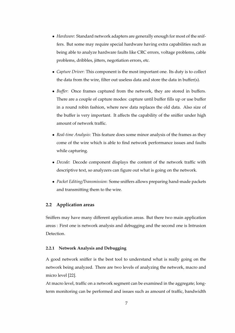
• Hardware: Standard network adapters are generally enough for most of the snif-
fers. But some may require special hardware having extra capabilities such as
being able to analyze hardware faults like CRC errors, voltage problems, cable
problems, dribbles, jitters, negotiation errors, etc.
• Capture Driver: This component is the most important one. Its duty is to collect
the data from the wire, filter out useless data and store the data in buffer(s).
• Buffer: Once frames captured from the network, they are stored in buffers.
There are a couple of capture modes: capture until buffer fills up or use buffer
in a round robin fashion, where new data replaces the old data. Also size of
the buffer is very important. It affects the capability of the sniffer under high
amount of network traffic.
• Real-time Analysis: This feature does some minor analysis of the frames as they
come of the wire which is able to find network performance issues and faults
while capturing.
• Decode: Decode component displays the content of the network traffic with
descriptive text, so analyzers can figure out what is going on the network.
• Packet Editing/Transmission: Some sniffers allows preparing hand-made packets
and transmitting them to the wire.
2.2 Application areas
Sniffers may have many different application areas. But there two main application
areas : First one is network analysis and debugging and the second one is Intrusion
Detection.
2.2.1 Network Analysis and Debugging
A good network sniffer is the best tool to understand what is really going on the
network being analyzed. There are two levels of analyzing the network, macro and
micro level [22].
At macro level, traffic on a network segment can be examined in the aggregate; long-
term monitoring can be performed and issues such as amount of traffic, bandwidth
7

problems, variation of network traffic during the day, existing network protocols,
amount of broadcast traffic, network errors and heaviest user of the network can be
learned.
In micro level, all data frames flowing on a network segment is captured, and the
captured data is analyzed by putting the sniffer in analysis mode. In analysis mode,
the contents of each individual data frame can be viewed.
Sniffers are also capable of providing graphical representation and statistics [23]. The
volume of traffic and systems in interaction is defined by the peer map. The data sup-
plies a quick and high-level account of traffic activity. Detailed statistics such as, the
exact percentage of network traffic attributed to a specific protocol (FTP, HTTP, etc)
are also supplied.
Analysis of conversation between client and server to determine the one causing de-
lay in an application, analysis of conversation between client and server to determine
the existence of retransmission due to packet drops, determination of occurances of
frozen windows in TCP/IP network conversations ( most likely meaning buffer-full
situation in either side), determination of the source of unwanted broadcasts, IP mul-
ticast data stream, excessive ICMP redirects, determination of routing table errors,
analysis of a security breach on the network, and determination of the way a partic-
ular network application is working can be considered as examples of usage of these
information in analyzing the network.
2.2.2 Intrusion Detection
An Intrusion Detection System (IDS) attempts to detect an intruder breaking into
your system or a legitimate user misusing system resources.
The primary assumptions of the intrusion detection are: user and program activities
are observable and more importantly, normal and intrusion activities have distinct
behavior. Thus, intrusion detection includes the following essential elements:
• Resources to be protected (user accounts,network services, OS kernels, etc.).
• Models that characterize the normal or legitimate behavior of the activities in-
volving these resources.
• Techniques that compare the observed activities with the established models.
8

In order to satisfy these, an IDS must have three components. First one is data col-
lection component, which preferably makes reduction also. Others are data classifi-
cation component and data reporting component.
Intrusions can be divided into 6 main types [24]:
• Attempted break-ins, which are detected by a typical behavior profiles or vio-
lations of security constraints
• Masquerade attacks, which are detected by atypical behavior profiles or viola-
tions of security constraints
• Penetration of security control system, which are detected by monitoring for
specific patterns of activity
• Leakage, which is detected by atypical usage of system resources
• Denial of service, which is detected by atypical usage of system resources
• Malicious use, which is detected by atypical behavior profiles, violations of
security constraints, or use of special privileges
An IDS can be classified according to the components they use. For example, they
can be classified into two groups according to data classification components, namely
anomaly detection and misuse detection. Other classification is done based on their
architecture: host-based or network based. One another classification is due to data
reporting component: passive or reactive systems.
2.2.2.1 Anomaly Detection
Anomaly detection is based on profiling [25]. Later, the decision is given due to the
deviation from the normal. The advantages of this system are as follows:
• It can be used to detect formerly unknown intrusions
• It is good at detecting masquerader
• It can also be used to detect insiders
Besides these advantages it has some drawbacks, such as :
9
• It can’t categorize attacks very well
• It produces too many false negatives and positives
• Its implementation can become computationally ineffective
2.2.2.2 Misuse Detection
Misuse detection systems are not unlike from virus detection systems. The main
issues in misuse detection systems are try to recognize known bad behaviors. They
write a signature or a pattern that encompasses all possible variations of attacks.
When they are writing signatures and patterns they also take care not to match non-
intrusive activities.
There have been several research in misuse detection systems recently [3]. Some of
these systems are:
• Expert Systems: The most known expert system is NIDES [26]. NIDES (Next
Generation Intrusion Detection Expert System), which is developed by SRI, is
a case study for expert systems. It uses a hybrid intrusion detection technique
consisting of a detection component. The detection component encodes known
intrusion scenarios and attack patterns. It generally uses statistical data and
looks for the attack control and solution separately. The expert systems are
generated by a security professional, so the program is only as strong as the
security personnel who programs it. There is a real chance that expert systems
can fail according to the programmers care.
• Keystroke Monitoring: It is a very simple technique that monitors keystrokes
for attack patterns. It only analyzes key strokes not processes.
• Model Based Intrusion Detection: It states certain scenarios with other observ-
able activities. If these activities are monitored, it will find intrusion attempts
by looking at activities that refers an observable intrusion scenario. It is very
clean approach, because it divides operation into modules, and all modules
know what to do. So it will be successful for detection. Also, it can filter the
noise of data.
10

• State Transition Analysis: In this technique, the monitored system is repre-
sented as a state transition diagram. While data is being analyzed, the sys-
tem changes its state from one to another. The state’s safety is determined for
known attacks, and when a transition is made, the state’s safety is checked.
• Pattern Matching: This model encodes known intrusion signatures as patterns,
then try to match against the audit data. If it matches the incoming events to
the patterns represented in known intrusion scenarios, it reports the event. The
most famous IDS that uses pattern matching is Snort [1].
2.2.2.3 Host-Based Intrusion Detection
Host-based intrusion detection systems are concerned with what is happening on
each individual host. They are able to detect such things as repeated failed access at-
tempts or changes to critical system files. Host-based IDS use audit logs and involve
sophisticated and responsive detection techniques. They typically monitor system,
event, and security logs. When any of these files change, the IDS compares the new
log entry with attack signatures to see if there is a match. If there is, the system re-
sponds with administrator alerts.
Since host-based IDS use logs containing events that have actually occurred, they can
measure whether an attack was successful or not with greater accuracy and fewer
false positives than network-based systems. Also, a host-based IDS monitors user
and file access activity, including full accesses, changes to file permissions, attempts
to install new executables and attempts to access privilege services. Because of such
attempts, host-based IDSs detect attacks that network-based IDSs would miss.
There are two main method for host-based IDS:
• Log Scanners: They monitor audit logs for intrusion detection.
• Integrity Checker: They monitor changes on a system file.
SNARE (System iNtrusion Analysis and Reporting Environment) [27], GrSecurity
[28], and CyberSafe [29] are example systems for host-based intrusion detection sys-
tems.
11
2.2.2.4 Network Based Intrusion Detection
Network based Intrusion Detection Systems are IDSes that gather and analyze net-
work packets to detect intrusions. Simple implementation and accurate detection of
intrusions occurring through a network are the advantages of these systems, where
as being unable to detect intrusions arising from within the system, particularly in a
switching environment is the disadvantage.
NetSTAT[30] and Snort[1] are two examples of most widely used network based in-
trusion detection systems.
Snort is a lightweight network intrusion detection system and sniffer capable of real-
time traffic analysis and misuse detection on IP networks [31]. Snort provides fea-
tures to support protocol and content analysis and is based on pattern matching tech-
niques [32]. There are three main modes in which Snort can be configured: sniffer,
packet logger, and network intrusion detection system [33]. Sniffer mode simply
reads the packets off of the network and displays them in a continuous stream on
the console. Packet logger mode logs the packets to the disk. Network intrusion de-
tection mode analyzes the network traffic for matches against a user defined rule set
and perform several actions based upon what it sees.
2.3 What to Sniff?
Many different kind of information can be obtained by sniffing the network. Data
sniffed from the network can be used in many areas as mentioned in section 2.2.
Generally, valuable information is sniffed through well-known ports. This valuable
information could be used for different applications like network debugging and
analysis or intrusion detection. However, valuable information also attracts the un-
derground people. One of the valuable information type is authentication informa-
tion, but sniffing is not limited to authentication information.
2.3.1 Authentication Information
Authentication information can be used to by-pass the system authentication mech-
anism, but sniffing this kind of information may also help administrator to improve
their system’s security. To get this kind of information sniffing must be done on
12

correct ports. Authentication mechanism is known for known applications on well-
known ports.
2.3.1.1 Telnet (Port 23)
Telnet was one of the favorite services for both users and attackers. Since packets in
the communication is sent as a plain text, an attacker may monitor the information
while somebody is attempting to login. However today, the usage of this service
significantly decreased due to its security.
2.3.1.2 FTP (Port 21)
The FTP service is used to transfer files among machines. Like telnet, it send its
authentication information in plain text. The FTP service can also be used for anony-
mous file access where arbitrary username and password is used.
2.3.1.3 POP (Port 110)
The Post Office Protocol (POP) service is used for accessing mails in a central mail
server. POP traffic is generally not an encrypted traffic, meaning sending authentica-
tion information as a plain text.
2.3.1.4 IMAP (Port 143)
The Internet Message Access Protocol (IMAP) service is an alternative protocol to the
POP service, and provides the same functionality. Like the POP protocol, authenti-
cation information is in many cases sent in plain text across the network.
2.3.1.5 NNTP (Port 119)
The Network News Transport Protocol (NNTP) supports the reading and writing
of Usenet newsgroup messages. NNTP authentication can occur in many ways. In
legacy systems, authentication was based primarily on a client’s network address, re-
stricting news server access to only those hosts (or networks) that were within a spec-
ified address range. Extensions to NNTP were created to support various authentica-
tion techniques, including plain text and encrypted challenge response mechanisms.
13
The plain text authentication mechanism is straightforward and can easily be cap-
tured on a network.
2.3.1.6 rexec (Port 512)
The rexec service, is a service used for executing commands remotely. rexec per-
forms authentication via plain text username and password information passed to
the server by a client. The service receives a buffer from the client consisting of a
port number, username, password and command to execute. If authentication is suc-
cessful, a NULL byte is returned by the server; otherwise, a value of 1 is returned in
addition to an error string.
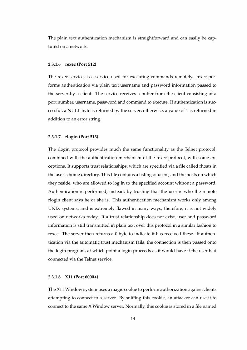
2.3.1.7 rlogin (Port 513)
The rlogin protocol provides much the same functionality as the Telnet protocol,
combined with the authentication mechanism of the rexec protocol, with some ex-
ceptions. It supports trust relationships, which are specified via a file called rhosts in
the user’s home directory. This file contains a listing of users, and the hosts on which
they reside, who are allowed to log in to the specified account without a password.
Authentication is performed, instead, by trusting that the user is who the remote
rlogin client says he or she is. This authentication mechanism works only among
UNIX systems, and is extremely flawed in many ways; therefore, it is not widely
used on networks today. If a trust relationship does not exist, user and password
information is still transmitted in plain text over this protocol in a similar fashion to
rexec. The server then returns a 0 byte to indicate it has received these. If authen-
tication via the automatic trust mechanism fails, the connection is then passed onto
the login program, at which point a login proceeds as it would have if the user had
connected via the Telnet service.
2.3.1.8 X11 (Port 6000+)
The X11 Window system uses a magic cookie to perform authorization against clients
attempting to connect to a server. By sniffing this cookie, an attacker can use it to
connect to the same X Window server. Normally, this cookie is stored in a file named
14

.Xauthority within a user’s home directory. This cookie is passed to the X Window
server by the xdm program at logon.
2.3.1.9 NFS File Handles
The Network File System (NFS) originally created by Sun Microsystems relies on
what is known as an NFS file handle to grant access to a particular file or directory
offered by a file server. By monitoring the network for NFS file handles, it is possible
to obtain this handle, and use it yourself to obtain access to the resource.
2.3.1.10 Windows NT Authentication
Windows operating systems support a number of different authentication types, each
of which progressively increase its security. The use of weak Windows NT authen-
tication mechanisms, as explained next, is one of the weakest links in Windows NT
security. The authentication types supported are explained here:
• Plain text Passwords are transmitted in the clear over the network
• LAN Manager (LM) Uses a weak challenge response mechanism where the
server sends a challenge to the client, which it uses to encrypt the user’s pass-
word hash and send it back to the server. The server does the same, and com-
pares the result to authenticate the user. The mechanism with which this hash
is transformed before transmission is very weak, and the original hash can be
sniffed from the network and cracked quite easily.
• NT LAN Manager (NTLM) and NT LAN Manager v2 (NTLMv2) NTLM and
NTLMv2 provide a much stronger challenge/response mechanism that has
made it much more difficult to crack captured authentication requests.
Specialized sniffers exist that support only the capture of Windows NT authentica-
tion information.
2.3.2 Other Network Traffic
Although sniffing the authentication information throughout ports, stated above, are
the most common ones, they are not the only ones that an attacker may find of inter-
est. A sniffer may be used to capture interesting traffic on other ports.
15
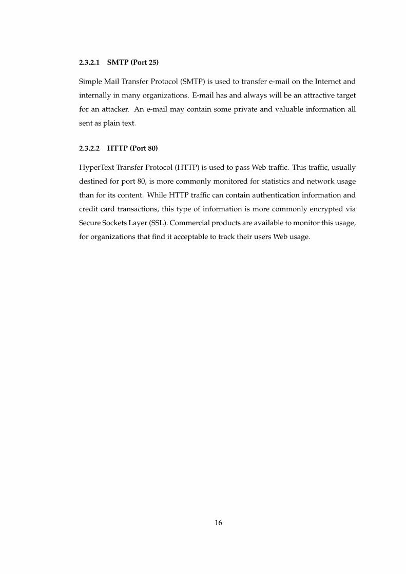
2.3.2.1 SMTP (Port 25)
Simple Mail Transfer Protocol (SMTP) is used to transfer e-mail on the Internet and
internally in many organizations. E-mail has and always will be an attractive target
for an attacker. An e-mail may contain some private and valuable information all
sent as plain text.
2.3.2.2 HTTP (Port 80)
HyperText Transfer Protocol (HTTP) is used to pass Web traffic. This traffic, usually
destined for port 80, is more commonly monitored for statistics and network usage
than for its content. While HTTP traffic can contain authentication information and
credit card transactions, this type of information is more commonly encrypted via
Secure Sockets Layer (SSL). Commercial products are available to monitor this usage,
for organizations that find it acceptable to track their users Web usage.
16

CHAPTER 3
DESIGN
It is the operating system that controls all the computer’s resources and provides the
base upon which the application programs can be written [34]. Kernel is the smallest
part of the operating system that does the real work. It acts as a mediator between
the programs and the hardware. Basic functions of it are memory management, pro-
viding interface for programs and sharing CPU cycles.
Sniffers working on computers should be in correlation with the operating system
kernel as all other applications. Linux is chosen as a case study in this thesis. Be-
cause Linux is a free, and open source operating system and its documentation is
better then most of the other operating systems. Since Linux is used, from this point
on; the term kernel will refer to the Linux kernel.
3.1 Networking in Linux Kernel
Networking related code in the Linux kernel can be seen in the figure 3.1. The direc-
tories include/net and include/linux, in the Linux kernel source tree, have header files
for the networking code. As the name implies net is the directory for the actual code.
core is the protocol independent common code directory, where packet directory con-
tent is the af packet specific code and ipv4’s is code related to IP version 4. Directory
named ethernet has the codes specific to Ethernet protocol and sched has the code for
scheduling the network actions.
The core structure of the networking code is based on initial networking and socket
17

asmarcDocumentationdriversfs
initipckernellibmmnet
include/
pcmcia
...
net
linux
802atm
ipv4ipx
coreethernet
packetsched...
Figure 3.1: Directory Tree for Networking Code in the Linux Kernel
implementations, and the key objects are:
• Device or Interface
• Protocol
• Socket
• Network Buffers
3.1.1 Network Devices
A network device is the entity that sends and receives data packets. It is normally a
physical device such as Ethernet card. An example for software devices is the loop
back device [35].
Each network device is represented by a data structure (see section 3.1.3) containing
18
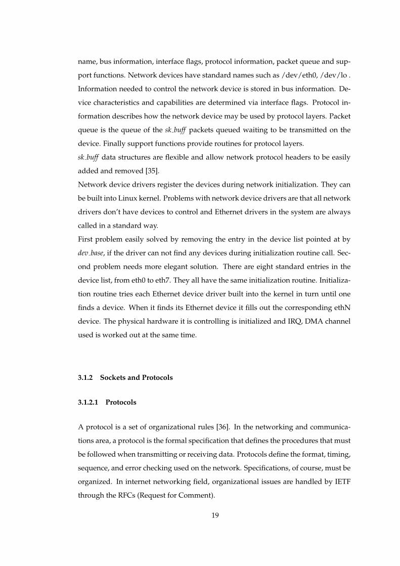
name, bus information, interface flags, protocol information, packet queue and sup-
port functions. Network devices have standard names such as /dev/eth0, /dev/lo .
Information needed to control the network device is stored in bus information. De-
vice characteristics and capabilities are determined via interface flags. Protocol in-
formation describes how the network device may be used by protocol layers. Packet
queue is the queue of the sk buff packets queued waiting to be transmitted on the
device. Finally support functions provide routines for protocol layers.
sk buff data structures are flexible and allow network protocol headers to be easily
added and removed [35].
Network device drivers register the devices during network initialization. They can
be built into Linux kernel. Problems with network device drivers are that all network
drivers don’t have devices to control and Ethernet drivers in the system are always
called in a standard way.
First problem easily solved by removing the entry in the device list pointed at by
dev base, if the driver can not find any devices during initialization routine call. Sec-
ond problem needs more elegant solution. There are eight standard entries in the
device list, from eth0 to eth7. They all have the same initialization routine. Initializa-
tion routine tries each Ethernet device driver built into the kernel in turn until one
finds a device. When it finds its Ethernet device it fills out the corresponding ethN
device. The physical hardware it is controlling is initialized and IRQ, DMA channel
used is worked out at the same time.
3.1.2 Sockets and Protocols
3.1.2.1 Protocols
A protocol is a set of organizational rules [36]. In the networking and communica-
tions area, a protocol is the formal specification that defines the procedures that must
be followed when transmitting or receiving data. Protocols define the format, timing,
sequence, and error checking used on the network. Specifications, of course, must be
organized. In internet networking field, organizational issues are handled by IETF
through the RFCs (Request for Comment).
19

3.1.2.2 Sockets
Socket is the interface between applications and protocol software. It is a de facto
standard and usually part of the operating system. Like file I/O, it is integrated with
the system I/O and works as open-read-write-close paradigm. There are a variety
of different types of sockets, differing in the way the address space of the sockets is
defined and the kind of communication that is allowed between sockets. A socket
type is uniquely determined by a <domain, type, protocol> triple [37].
3.1.3 Network Buffers
Either for sending a packet or receiving a packet network buffers, named sk buff,
referring to socket buffer, (figure 3.2) are used. sk buff data structure is defined in
include/linux/sk buff.h. When a packet arrives to the kernel, either from the user space
or from the network card one of these structures is created. Changing packet fields is
achieved by changing its fields [38].
The first fields are general ones. Two pointers, one for next and one for previous skbs,
to show corresponding skbs in the list. Packets frequently put in lists or queues. The
owning socket is pointed by sk.
Stamp stores the time of arrival, while the dev field storing the device that the packet
arrived and when and if the device to be used for transmission is known.
The union h stores the pointer for one of transport layer structure like TCP, UDP,
ICMP, etc. Corresponding data structures (IPv4, IPv6, arp, raw, etc) are pointed by
the network layer header, nh. Link layer header is stored in the union mac. If the
link layer protocol used is Ethernet, ethernet field of this union is used. All other
protocols use the raw field.
The rest of the fields below link layer header is used to store information about the
packet like length, data length, checksum, packet type, security level, etc.
3.1.4 Sending a Packet
Each packet contains dst field which determines the output method. When sending
a packet:
1. For each packet to be transmitted corresponding method’s function is called.
20

struct sk_buff {/* These two members must be first. */struct sk_buff * next; /* Next buffer in list */struct sk_buff * prev; /* Previous buffer in list */
struct sk_buff_head * list; /* List we are on */struct sock *sk; /* Socket we are owned by */struct timeval stamp; /* Time we arrived */struct net_device *dev; /* Device we arrived on/are leaving by *//* Transport layer header */union{
struct tcphdr *th;struct udphdr *uh;struct icmphdr *icmph;struct igmphdr *igmph;struct iphdr *ipiph;struct spxhdr *spxh;unsigned char *raw;
} h;/* Network layer header */union{
struct iphdr *iph;struct ipv6hdr *ipv6h;struct arphdr *arph;struct ipxhdr *ipxh;unsigned char *raw;
} nh;/* Link layer header */union{
struct ethhdr *ethernet;unsigned char *raw;
} mac;
struct dst_entry *dst;
/** This is the control buffer. It is free to use for every* layer. Please put your private variables there. If you* want to keep them across layers you have to do a skb_clone()* first. This is owned by whoever has the skb queued ATM.*/char cb[48];
unsigned int len; /* Length of actual data */unsigned int data_len;unsigned int csum; /* Checksum */unsigned char __unused, /* Dead field, may be reused */cloned, /* head may be cloned (check refcnt to be sure). */pkt_type, /* Packet class */ip_summed; /* Driver fed us an IP checksum */__u32 priority; /* Packet queueing priority */atomic_t users; /* User count - see datagram.c,tcp.c */unsigned short protocol; /* Packet protocol from driver. */unsigned short security; /* Security level of packet */unsigned int truesize; /* Buffer size */
unsigned char *head; /* Head of buffer */unsigned char *data; /* Data head pointer */unsigned char *tail; /* Tail pointer */unsigned char *end; /* End pointer */
void (*destructor)(struct sk_buff *); /* Destruct function */#ifdef CONFIG_NETFILTER
/* Can be used for communication between hooks. */unsigned long nfmark;/* Cache info */__u32 nfcache;/* Associated connection, if any */struct nf_ct_info *nfct;#ifdef CONFIG_NETFILTER_DEBUG
unsigned int nf_debug;#endif
#endif /*CONFIG_NETFILTER*/#if defined(CONFIG_HIPPI)
union{__u32 ifield;
} private;#endif#ifdef CONFIG_NET_SCHED
__u32 tc_index; /* traffic control index */#endif};
Figure 3.2: sk buff Data Structure in the Linux Kernel 2.4.20
21

2. Then virtual method, namely hard start xmit(), is called. The packet descriptor
in put in tx ring buffer and NIC is informed.
3. As the packet sent, card communicates with CPU and reports that he sent some
packets [38] via net tx action() function. The CPU , then schedules a softirq for
further processing like deallocating memory locations. CPU-card communica-
tion is driver-dependent communication.
3.1.5 Receiving a Packet
Packets not only contains data for the higher layer, but also they provide information
about data’s physical location, data length and some more control and status infor-
mation. Usually NIC driver sets up the packet descriptors and organizes them as
ring buffers when the driver is loaded [38]. tx and rx ring buffers are used by NIC
DMA engine for sending and receiving correspondingly and managed by the inter-
rupt handler.
Packet receive process can be examined step by step:
1. When a packet is received by the kernel, DMA engine puts the packet in rx ring
buffer in the kernel memory. The size of the ring driver and hardware depen-
dent [38].
2. The CPU, interrupted by the card, jumps to the driver ISR code. There is a
difference between old network subsystem and NAPI at this point. Interrupt
handler call the netif rx() kernel function in net/core/dev.c. This functions en-
queues the packet in the interrupted CPU’s backlog queue and schedules a
softirq. Softirq is responsible for further processing of the packet. If the backlog
queue becomes full, it changes its state to throttle. In throttle state CPU waits for
being totally empty before reentering normal state and allowing again packet
enqueueing. netif rx drops the packet if the backlog queue is in throttle state
[38].
NAPI’s situation is a bit different. Interrupt handler calls netif rx schedule. It
puts a reference to the device in a queue attached to the interrupted CPU, in-
stead of putting the packets into the backlog queue. Like older subsystem,
scheduling of a softirq is done. Backlog is also implemented as a device in
22

NAPI in the kernel for backward compatibility. netif rx function is used only
in case of non-NAPI drivers and enqueues the backlog into the poll list of the
CPU after having enqueued the packet into the backlog [38].
3. Scheduling of softirq leads to execution of net rx action() which takes place in
net/core/dev.c. This step is also different for old subsystems and NAPI.
In old subsystems, net rx action() polls all the packets in the backlog queue and
calls related receive procedure for each packet [39] (see figure 3.3). The NAPI
is much more efficient than the old system. The pros are limitation of interrup-
tion rate, not being prone to receive live lock, better data and better instruction
locality [38].
libpcap based sniffers use AF PACKET type sockets. The path of the sniffers in the
figure 3.3 is same as others till Derefferred Packet Reception. At this point, sniffers fol-
low AF PACKET processing branch. After sending data ready signal packets advance
to Socket Level and later to Receiving Process.
23

Socket Level
EthernetDriver
Lower−LevelPacket Reception
Dereffered PacketReception
Protocol HandlersOther Layer 3 AF_INET(IP)
ProcessingAF_PACKETProcessing
[netif_rx_action()]softirq
Packet Arrival
*_rcv() ip_rcv() packet_rcv()
icmp_rcv()tcp_rcv() udp_rcv()
data_ready() data_ready() data_ready()
TCP Processing UDP Processing ICMP Processing
netif_rx()
wake_up_interruptable()
Receiving Process
Figure 3.3: Flow Diagram for Receiving a Packet
24

CHAPTER 4
IMPLEMENTATION
To follow a systematic way, implementation is divided into six steps: Configur-
ing Kernel, Omitting IP processing, Modifying AF PACKET Receive Functions, By-
passing CPU Queue, Arranging Network Buffers and Modifying Ethernet Driver.
Kernel Configuration is done first, and then other five steps are applied over this
kernel configuration. Finally, two alternative combination of the steps is presented.
Detailed test results of each step and alternatives are given in section 5.4.
4.1 Step 1: Configuring Kernel
Default kernel, coming with Redhat Linux distribution, has lots of features to serve
different purposes. Since this kernel will be used for a special purpose, most of these
features are not needed and may be eliminated for a smaller footprint in terms of
system memory.
When configuring kernel, Linux provides various user interfaces. In all of these in-
terfaces configuration details are collected under different configuration titles.
• Code Maturity Level Options:
This section is about developing incomplete drivers and codes. For our special
purpose this kind of support is not needed.
• Loadable module support:
As the name implies this is support for loadable modules. For a faster kernel
25

all the functions needed for networking events should be in kernel code itself,
not as kernel modules.
• Processor type and features:
Under this title different kinds of processor family is supported. Configu-
ration for SMP (Symmetric Multi-Processing) and High Memory support is
done here. Since the machine used for tests has only one PII processor and
64MB memory, as will be described in section 5.1, Processor family ”Pentium
Pro/Celeron/Pentium II” is set and support for SMP and High memory is dis-
abled in the configuration.
• General Setup :
This section is to define a route for the rest of the configuration. Subsections for
this section are
– Networking Support : Obviously necessary.
– PCI Support : Necessary because network card is a PCI device.
– EISA Support : No Extended ISA cards in the system.
– Hot plug device support : Not needed
– System V IPC: May be useful for IPC
– BSD Process Accounting : Process accounting is not needed.
– Sysctl support: Useful addition to kernel
– Power Management Support : Not needed
– Advanced Power Management Support : Not needed
• Memory Technology Devices(MTD):
MTD devices are flash, RAM and similar chip, often used for solid state file
systems on embedded devices. This option provides the generic support for
this kind of devices. In the system there no such devices so this option is not
needed.
• Parallel Port Support:
Parallel port support is not necessary because no parallel devices will be used
during sniffing.
26

• Plug and Play Configuration:
System is thought to be static with a minimum hardware complexity. No addi-
tional devices will be plugged, nor removed during its operation.
• Block Devices:
Includes Normal PC floppy disk, XT hard disk support etc. Not needed.
• Multi Device Support (Raid and LVM):
System has only 1 about 4GB disk.
• Networking Options:
Most critical part of configuration for the study is under this part Supports
chosen here are expected to have dramatic effects on sniffing.
– Packet Socket: To use libpcap this is a mandotary option. Also to over-
come lots of memcpy overhead MMAP support for packet socket is en-
abled.
– Network Packet Filtering: Netfilter is a framework for filtering and man-
gling network packets. Needed when Linux is configured as a firewall but
in this case system is not a firewall.
– Socket Filtering: Filtering of the packets may be done by the application.
It is not needed here.
– Unix domain sockets: Most systems use unix sockets even they are not
connected to network. So support is added to the configuration.
– TCP/IP networking: Adds related protocols and necessary handling func-
tions to the network subsystem.
– IP- multicasting: All packets are captured regardless of being a multicast,
unicast or broadcast packet. No special treatment needed for this kind of
packets. Taken out from the configuration.
– IP- advanced router: not serves the purpose of the system.
– QoS and/or Fair Queuing: again not related to the system.
• Telephony Support:
Nothing to do with telephony support.
27

• ATA/IDE/MFM/RLL Support:
This option provides low cost mass storage handling for the kernel. Many
kinds of devices included here:
– IDE/ATAPI TAPE Support: System does not have a tape device.
– IDE/ATAPI CDROM Support: Although system has a cdrom it doesn’t
have usage during system’s operation. Therefore support for IDE/ATAPI
CDROM is omitted.
– IDE/ATAPI Floppy Support: Not needed with the same reason with the
cdrom support.
– PCMCIA IDE Support: No PCMCIA cards.
– IDE Chipsets: Suitable chipset is chosen to have a faster I/O on the disk.
• SCSI Support:
SCSI devices have much more faster I/O than IDE devices. This will also effect
the performance of the application while logging. Since the system used has an
IDE disk, we don’t need this support. But replacing disk with a SCSI one may
lead to a better performance, then IDE disk support would be unnecessary.
• Fusion MPT device support:
This message passing technology is not used.
• I2O Device Support:
This I/O architecture does not exist in the system used.
• Network Device Support:
All devices but the Ethernet card in the system are unnecessary in the con-
figuration. Among Ethernet cards, ”3c590/3c900 series (592/595/597) Vor-
tex/Boomerang support” is added to the configuration.
FDDI Support, Token Ring Devices, Wireless LAN, WAN Interfaces, SLIP Sup-
port is not needed.
• Amateur Radio Support:
Not related.
28
• IrDA support:
Not related.
• ISDN Subsystem:
Not needed, because systems aimed to run over Ethernet.
• Old CD-ROM drivers:
Not needed.
• Input Core Support:
System does not have USB HID devices. Thus, not needed.
• Character Devices:
Needed for terminal communication.
• Multimedia Devices:
System does not have video devices. Even if it has they are not needed
• File Systems:
Features like quota support, kernel automounter support are not needed. As
a file system system has ext3 formatted Linux root partition with journalling
enabled. Kernel support for both is mandatory, but other file system supports
such as FAT 16, FAT 32, NTFS, ISO9660, etc are not needed. Also network file
system support and support for advanced partition types are just overheads.
• Console Drivers:
Driver needed for VGA text console.
• Sound:
Sound card and drivers are not necessary.
• USB Support:
Although some USB ports exist on the motherboard of the system, no devices
attached to them.
• Bluetooth support:
Not needed.
29

• Kernel hacking:
Not needed.
Having the kernel configured this way, size of the new kernel is at least two times
less than the size of the original kernel. This provides more memory to other ap-
plications. Disabling support for many features removes the overhead for checking
them. For example, in networking options if socket filtering option is enabled, kernel
will at least be checking whether a socket filter is active or not. Many of such checks
are prevented by this kernel configuration. One another benefit of this kernel config-
uration is that it reduces the number of interrupts generated. A CD-Rom would not
be generating an interrupt since it is not supported in this kernel. All these comes
out with a decrease in packet loss by around 50%.
4.2 Step 2: Modifying AF PACKET Receive Functions
For packet socket type sockets, receive function is tpacket rcv which can be found in
af packet.c in net/packet directory. As packet arrives to this function, packet type is
checked first. Function does not deal with loopback packets and drops them. Next
check is socket type check. Some status check and alignment is done according to
socket type. It is known that Ethernet card used has hard header control. Therefore,
check for this feature is not needed.
After some memory allocation process, if packet is a shared one it is cloned. Since
a packet will only be sent to one packet socket this step is unnecessary, so it can be
eliminated (see figure 4.1). Next is snaplen and mmap options arrangement.
After that sll header structure is filled. Last work to do is setting owner of the
packet and entailing packet to socket’s receive queue for the application and sending
data ready signal to the sleeping process.
This function is called for every packet received. Any change in this function directly
affects the network performance. In this step, conditional checks and impossible con-
ditions are eliminated. Little performance improvement is observed after this step.
30

if (skb_shared(skb)) {copy_skb = skb_clone(skb, GFP_ATOMIC);
}
. . .
if (skb_head != skb->data && skb_shared(skb)) {skb->data = skb_head;skb->len = skb_len;
}
Figure 4.1: Packet is not shared and it needn’t be cloned
4.3 Step 3: Omitting IP processing
Sockets can be categorized into two groups. First group is formed by the sockets that
requests any packet from the network. They have Ethernet Protocol ID defined by
macro ETH P ALL. The name implies ”all Ethernet packets”. All other kind of nor-
mal sockets form the second group.
Kernel keeps listings of the sockets according to their group. Whenever a socket is
opened, it registers himself. If socket is in the first group it is entailed to the link list
whose header is determined by the pointer ptype all. Others registered to the link list
pointed by ptype base’s array’s corresponding protocol element.
As the packet arrives from Ethernet card’s buffer, it is first delivered to all sockets
registered to first type. This is achieved by piece of code in figure 4.2. This code ex-
ists in netif receive skb function in net/core/dev.c. Code walks through all this kind of
sockets and calls their handler function. As the handler function called it clones the
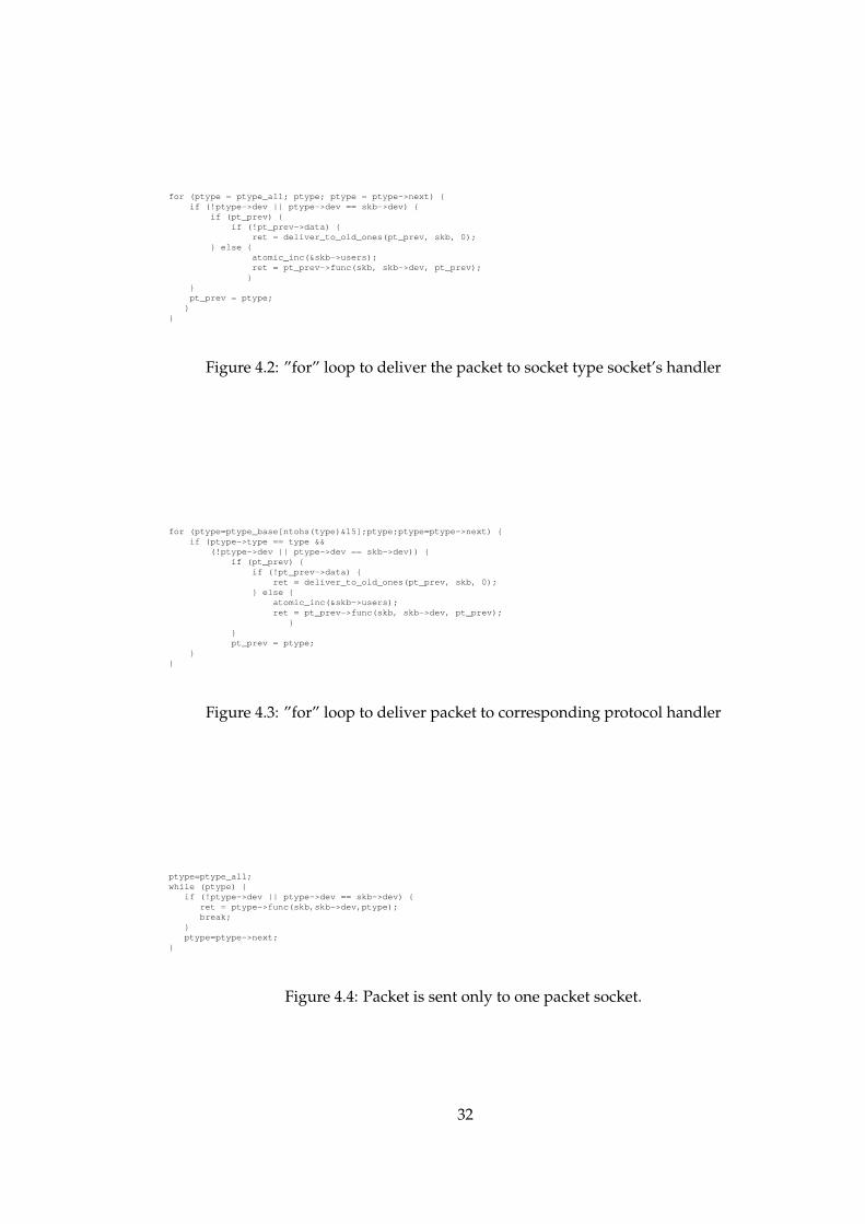
packet for itself and processes it.
Next is delivering the packet to corresponding protocol handler. (see for loop in fig-
ure 4.3). Code finds the registered socket entry in ptype base array and walks through
each socket in the linked list. Packet is delivered to the corresponding handler. This
completes the delivering of the packet.
However, in case of sniffing, delivering packet to upper layer protocol handlers is not
needed. Thus, the code in figure 4.3 can be eliminated. Furthermore, since the com-
puter running sniffer for this thesis is a controlled one and only one socket is open for
requesting all packets loop is not needed in the code in figure 4.2. As a result these
two pieces of code can be replaced by simple piece in figure 4.4.
Normally, a packet follows the three steps shown in figure 3.3. After the third
31
for (ptype = ptype_all; ptype; ptype = ptype->next) {if (!ptype->dev || ptype->dev == skb->dev) {
if (pt_prev) {if (!pt_prev->data) {
ret = deliver_to_old_ones(pt_prev, skb, 0);} else {
atomic_inc(&skb->users);ret = pt_prev->func(skb, skb->dev, pt_prev);
}}pt_prev = ptype;
}}
Figure 4.2: ”for” loop to deliver the packet to socket type socket’s handler
for (ptype=ptype_base[ntohs(type)&15];ptype;ptype=ptype->next) {if (ptype->type == type &&
(!ptype->dev || ptype->dev == skb->dev)) {if (pt_prev) {
if (!pt_prev->data) {ret = deliver_to_old_ones(pt_prev, skb, 0);
} else {atomic_inc(&skb->users);ret = pt_prev->func(skb, skb->dev, pt_prev);
}}pt_prev = ptype;
}}
Figure 4.3: ”for” loop to deliver packet to corresponding protocol handler
ptype=ptype_all;while (ptype) {
if (!ptype->dev || ptype->dev == skb->dev) {ret = ptype->func(skb,skb->dev,ptype);break;
}ptype=ptype->next;
}
Figure 4.4: Packet is sent only to one packet socket.
32

Socket Level
EthernetDriver
Lower−LevelPacket Reception
Dereffered PacketReception
AF_INET(IP)Processing
AF_PACKETProcessing
[netif_rx_action()]softirq
Protocol HandlersOther Layer 3
Packet Arrival
*_rcv() ip_rcv() packet_rcv()
icmp_rcv()tcp_rcv() udp_rcv()
data_ready() data_ready() data_ready()
TCP Processing UDP Processing ICMP Processing
netif_rx()
wake_up_interruptable()
Receiving Process
Figure 4.5: Flow Diagram for Receiving a Packet After Omitting IP Processing
step, the packet is cloned and sent to AF PACKET Processing that is for sniffing. Orig-
inal packet follows the way AF INET Processing (IP Processing) and upper steps till
the application. But after this step is applied, packet is not cloned and it is only sent
to AF PACKET Processing. In other words, figure 3.3 becomes figure 4.5.
4.4 Step 4: By-passing CPU Backlog Queue
Whenever a packet arrives to Ethernet card, Ethernet card takes it to his buffer and
wakes up Ethernet driver. Ethernet driver receive function, boomerang rx for 3com
card the machine has, calls netif rx function after little process on the packet. netif rx
33

Packet
Socket Queue
Socket Queue
Interrupt Action
Backlog Queue
CPU
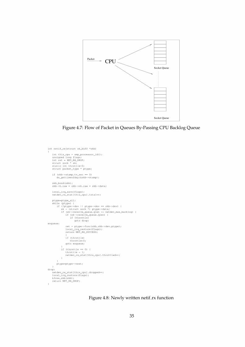
Figure 4.6: Flow of Packet in Queues
is in dev.c under net/core directory. Normally in this function CPU takes the packet
and entails it in its backlog queue and raises soft irq. Action that should be taken
when this soft irq is raised is the function named netif rx action. This function is the
one that sends packet to protocol handlers and protocol handlers put the packet to
the socket’s queue after some processing as stated in section 4.2.
For sniffing the path that packet should take is known. Thus entailing the packet
first in CPU’s own queue and later taking it from this queue and entailing it to the
socket’s queue is just an overhead. Instead, packet may directly be put into socket’s
receive queue. To achieve this, netif rx function can be rewritten as in figure 4.8.
Packet is timestamped first if it was not. After saving interrupt requests, packet count
is incremented. Performance effective part of code comes next. Arrived packet is di-
rectly put to related socket’s queue. Then interrupt requests are restored. Figure 4.6
and 4.7 depicts the picture of this step. First one shows the normal processing of the
packet while the second is the processing after the modification. In SMP (Symmetric
Multi Processors) boxes, each CPU has its own backlog queue. This modification still
holds for SMP boxes, each CPU would be directly putting the packet it received to
the related socket. The majority of the improvement of the thesis is obtained in this
step.
34
Packet
Socket Queue
Socket Queue
CPU
Figure 4.7: Flow of Packet in Queues By-Passing CPU Backlog Queue
int netif_rx(struct sk_buff *skb){
int this_cpu = smp_processor_id();unsigned long flags;int ret = NET_RX_DROP;struct sock * sk;static int throttle=0;struct packet_type * ptype;
if (skb->stamp.tv_sec == 0)do_gettimeofday(&skb->stamp);
skb_bond(skb);skb->h.raw = skb->nh.raw = skb->data;
local_irq_save(flags);netdev_rx_stat[this_cpu].total++;
ptype=ptype_all;while (ptype) {
if (!ptype->dev || ptype->dev == skb->dev) {sk = (struct sock *) ptype->data;if (sk->receive_queue.qlen <= netdev_max_backlog) {
if (sk->receive_queue.qlen) {if (throttle)
goto drop;enqueue:
ret = ptype->func(skb,skb->dev,ptype);local_irq_restore(flags);return NET_RX_SUCCESS;}if (throttle)
throttle=0;goto enqueue;
}if (throttle == 0) {
throttle = 1;netdev_rx_stat[this_cpu].throttled++;
}}ptype=ptype->next;
}drop:
netdev_rx_stat[this_cpu].dropped++;local_irq_restore(flags);kfree_skb(skb);return NET_RX_DROP;
}
Figure 4.8: Newly written netif rx function
35
4.5 Step 5: Arranging Network Buffers
Packets are discarded if the receive buffer of the socket is full. Size of socket buffer is
stated in sock.h under include/net directory with the defines below:
#define SOCK_MIN_SNDBUF 2048
#define SOCK_MIN_RCVBUF 256
For normal Linux client packets sent are generally much more than packets received.
Therefore, size of send buffer for each socket is larger than the socket’s receive buffer.
However, the machine used in this thesis would not be an active one would only sniff
the packets on the wire, meaning packets received would be absolutely dominant.
With the small sized receive buffer, buffer would fill up quickly resulting in more
packet loses.
Setting the values as below is expected to solve this problem.
#define SOCK_MIN_SNDBUF 256
#define SOCK_MIN_RCVBUF 4096
Size of send buffer is decreased to save memory space.
4.6 Step 6: Modifying Ethernet Driver
This step is totally depended on which Ethernet card is being used. Improvement in
the Ethernet card driver means decreasing time spent for each packet, coders of the
driver had made the code as optimized as possible. Only debug conditional could be
eliminated from the driver’s code. Even these eliminations affected the performance,
but this effect is not so high.
4.7 Alternative 1:
One of the alternative systems using the steps, implemented individually, may be
combination of configuring kernel, modifying AF PACKET receive functions, omit-
ting IP processing, arranging network buffers and modifying Ethernet driver. This
combination uses the advantage of all steps involved but the dominant steps are the
first and fourth steps, that are kernel configuration and omition of the IP processing.
36
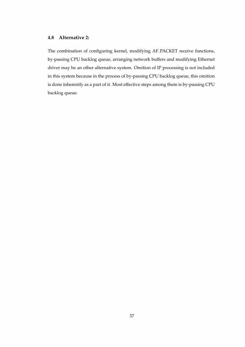
4.8 Alternative 2:
The combination of configuring kernel, modifying AF PACKET receive functions,
by-passing CPU backlog queue, arranging network buffers and modifying Ethernet
driver may be an other alternative system. Omition of IP processing is not included
in this system because in the process of by-passing CPU backlog queue, this omition
is done inherently as a part of it. Most effective steps among them is by-passing CPU
backlog queue.
37

CHAPTER 5
TEST RESULTS and COMPARISON
5.1 Test Environment
Test environment is very important for accurate test results. Test can not be done in
real environment, because achieving fully controlled tests is impossible. Controlled
tests is required for performance comparison. Data flow is changing continuously in
real networks, one can not get same density, same speed, data with same characteris-
tics, etc at different times. Best way is preparing a synthetic closed environment (see
figure 5.1). Actually, It is really hard to simulate real environments, but this synthetic
closed environment may be close to the real environment. Some tools exist to replay
the captured network scenario. Tool used in this thesis is tcpreplay [40]. Tcpreplay
simply opens a tcpdump file, forms the corresponding packets and puts the packet
on the wire. Two options of tcpreplay is used for this thesis. -i option specifies the
interface that packet should be put and -r option determines the speed in terms of
megabits per second. Synopsis of the tcpreplay can be seen in figure 5.2.
PC chosen for development and tests is a Pentium II PC with 350 MHz clock speed.
The PC has 64MB memory. This low configuration is chosen because generally faster
CPUs increases the bottleneck speed, which would make tests more difficult. Four
3Com EtherXL PCI network interface cards are connected to this PC. EtherXL is a
10/100 Fast Ethernet card. At its maximum rate that is 100Mbit/s kernel hardly
loose packets. Packet lost starts at around 220 Mbits/s. Upper limit is four Ethernet
cards, because the PC has only four PCI slots. Detailed properties of development
38
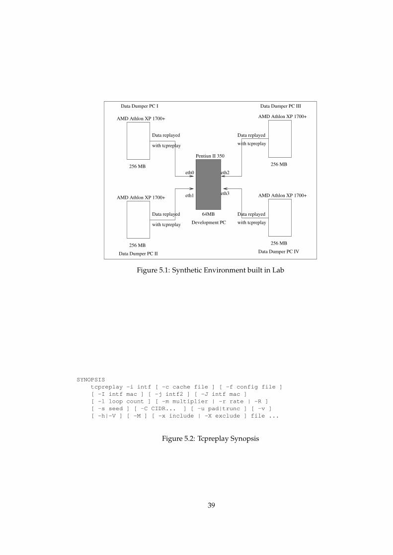
Data Dumper PC IV
AMD Athlon XP 1700+
256 MB
Data replayed
with tcpreplay
AMD Athlon XP 1700+
256 MB
Data replayed
with tcpreplay
AMD Athlon XP 1700+
256 MB
Data replayed
with tcpreplay
Data replayed
with tcpreplay
AMD Athlon XP 1700+
256 MB
eth0
eth1
eth2
eth3
Pentiun II 350
64MB
Development PC
Data Dumper PC I
Data Dumper PC II
Data Dumper PC III
Figure 5.1: Synthetic Environment built in Lab
SYNOPSIStcpreplay -i intf [ -c cache file ] [ -f config file ][ -I intf mac ] [ -j intf2 ] [ -J intf mac ][ -l loop count ] [ -m multiplier | -r rate | -R ][ -s seed ] [ -C CIDR... ] [ -u pad|trunc ] [ -v ][ -h|-V ] [ -M ] [ -x include | -X exclude ] file ...
Figure 5.2: Tcpreplay Synopsis
39
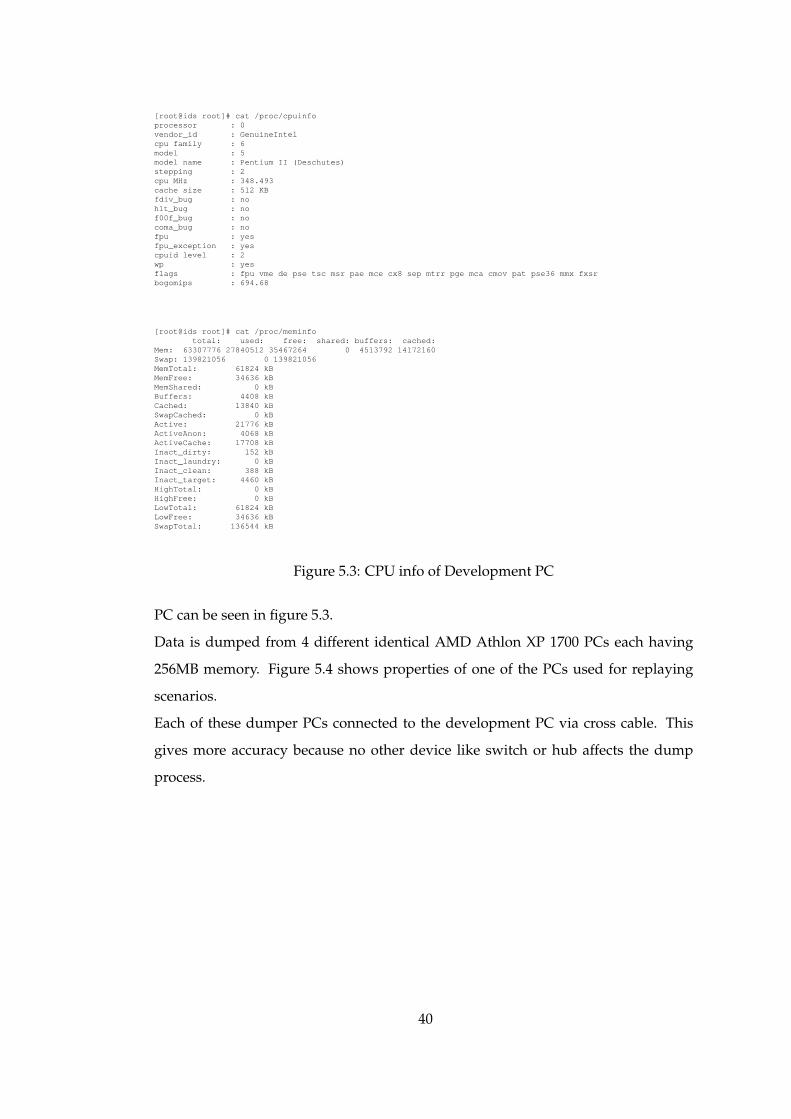
[root@ids root]# cat /proc/cpuinfoprocessor : 0vendor_id : GenuineIntelcpu family : 6model : 5model name : Pentium II (Deschutes)stepping : 2cpu MHz : 348.493cache size : 512 KBfdiv_bug : nohlt_bug : nof00f_bug : nocoma_bug : nofpu : yesfpu_exception : yescpuid level : 2wp : yesflags : fpu vme de pse tsc msr pae mce cx8 sep mtrr pge mca cmov pat pse36 mmx fxsrbogomips : 694.68
[root@ids root]# cat /proc/meminfototal: used: free: shared: buffers: cached:
Mem: 63307776 27840512 35467264 0 4513792 14172160Swap: 139821056 0 139821056MemTotal: 61824 kBMemFree: 34636 kBMemShared: 0 kBBuffers: 4408 kBCached: 13840 kBSwapCached: 0 kBActive: 21776 kBActiveAnon: 4068 kBActiveCache: 17708 kBInact_dirty: 152 kBInact_laundry: 0 kBInact_clean: 388 kBInact_target: 4460 kBHighTotal: 0 kBHighFree: 0 kBLowTotal: 61824 kBLowFree: 34636 kBSwapTotal: 136544 kB
Figure 5.3: CPU info of Development PC
PC can be seen in figure 5.3.
Data is dumped from 4 different identical AMD Athlon XP 1700 PCs each having
256MB memory. Figure 5.4 shows properties of one of the PCs used for replaying
scenarios.
Each of these dumper PCs connected to the development PC via cross cable. This
gives more accuracy because no other device like switch or hub affects the dump
process.
40
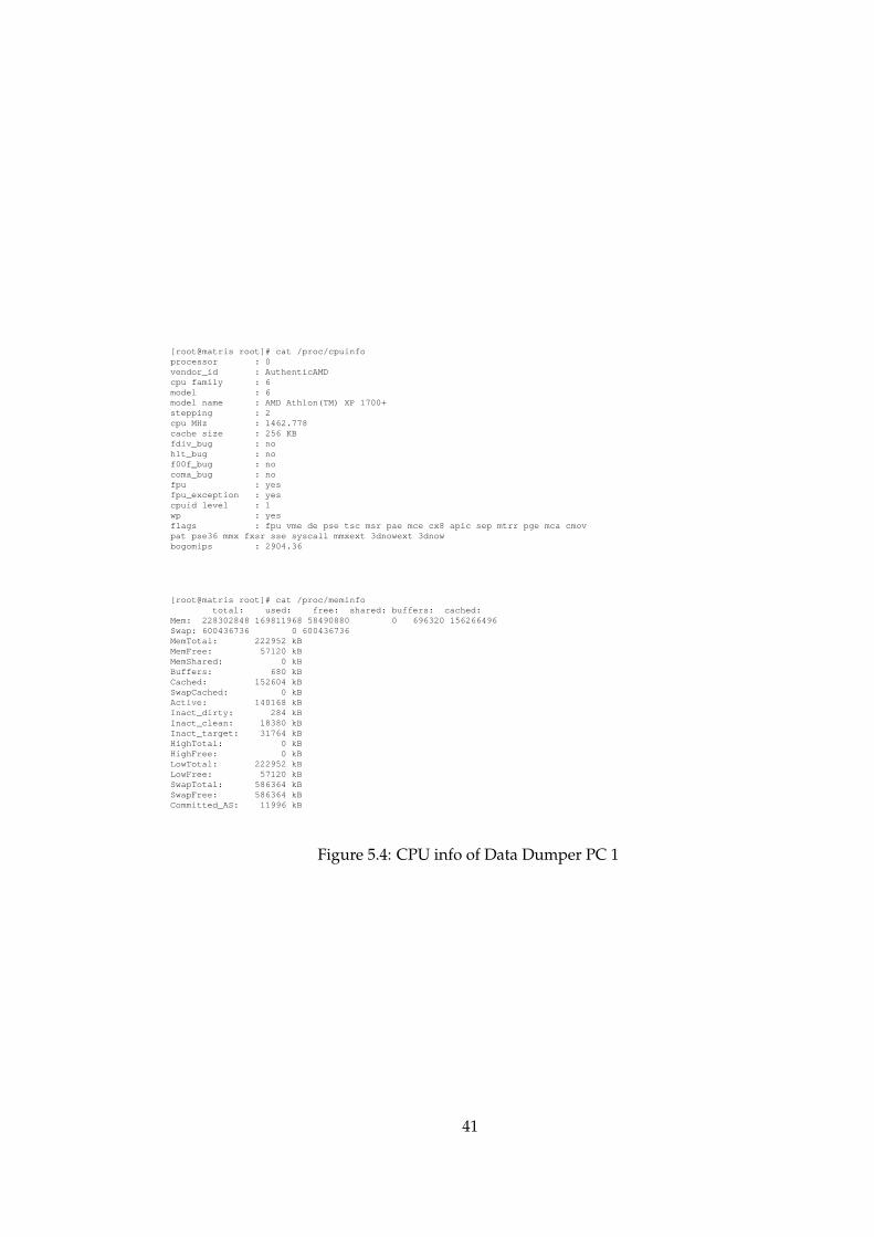
[root@matris root]# cat /proc/cpuinfoprocessor : 0vendor_id : AuthenticAMDcpu family : 6model : 6model name : AMD Athlon(TM) XP 1700+stepping : 2cpu MHz : 1462.778cache size : 256 KBfdiv_bug : nohlt_bug : nof00f_bug : nocoma_bug : nofpu : yesfpu_exception : yescpuid level : 1wp : yesflags : fpu vme de pse tsc msr pae mce cx8 apic sep mtrr pge mca cmovpat pse36 mmx fxsr sse syscall mmxext 3dnowext 3dnowbogomips : 2904.36
[root@matris root]# cat /proc/meminfototal: used: free: shared: buffers: cached:
Mem: 228302848 169811968 58490880 0 696320 156266496Swap: 600436736 0 600436736MemTotal: 222952 kBMemFree: 57120 kBMemShared: 0 kBBuffers: 680 kBCached: 152604 kBSwapCached: 0 kBActive: 140168 kBInact_dirty: 284 kBInact_clean: 18380 kBInact_target: 31764 kBHighTotal: 0 kBHighFree: 0 kBLowTotal: 222952 kBLowFree: 57120 kBSwapTotal: 586364 kBSwapFree: 586364 kBCommitted_AS: 11996 kB
Figure 5.4: CPU info of Data Dumper PC 1
41

d i g� i t a l
Hub
Sniffer Serverm� on� it
�orin� g/a� nal
�ysis
Sniffer
Router
Internet
Bay� Net�works
Backbone Switch
Router
RemoteCampus #2
RemoteCampus #1
RemoteCampus #3
Primary CampusNetwork
Figure 5.5: Network topology of Ankara University
METUCENG NET171
(Multiple Servers andWorkstations)
METU CampusNetwork
CISCOS�
YSTEMS
Backbone Switch
D�
a� t�a Ge� n� e� r� al
LinuxGateway(Sniffer)
METUCENG NET71
(Multiple Servers andWorkstations)
Figure 5.6: Network topology of Dept. of Computer Engineering, METU
5.2 Test Data
Data collected also plays an important role in accuracy of the test results. With biased
results performance can change drastically. Data collected from two different sites’
real network traffic.
First site is Ankara University. Ankara University has a heterogeneous network with
various kinds of servers and workstations with different operating systems. Data
collection position can be seen in figure 5.5 adapted from [32].
The second site that data is collected is Department of Computer Engineering in Middle
East Technical University. Department Network has various kinds of servers running
different kind of operating systems on them. Network structure can be seen in figure
5.6 adapted from [32].
Packets are captured from the live environment of these two sites. Table 5.1 shows
42

Table 5.1: Properties of Data Collected from Ankara University
Size of Packets 1.559.876.508 bytesNumber of Packets 3.500.000Capture Start Date Fri Aug 3 11:38:01 2001Capture End Date Fri Aug 3 15:00:18 2001
Table 5.2: Properties of Data Collected from CEng, METU
Size of Packets 1.661.297.351 bytesNumber of Packets 3.864.834Capture Start Date Wed Feb 6 13:02:24 2002Capture End Date Wed Feb 6 14:22:26 2002
the properties of the data collected from Ankara University. Data is collected in two
and a half hours. During these two hours, 3.500.000 packets were capture which to-
tally makes a file of 1.559.876.508 bytes.
These captured files are previously used in [32]. They are kept safe for use in this the-
sis. Duration for packet capture in Department of Computer Engineering (CEng),
in Middle East Technical University (METU) is about one hour and 20 minutes.
3.864.834 packets are collected using tcpdump. Total size of packets is 1.661.297.351
bytes. More details about the captured file can be seen in table 5.2.
5.3 Test Scenario
Laboratory environment is formed first(see section 5.1). 5 PCs are connected as in
figure 5.1. Each of four dumper PCs are connected via cross cables. This will prevent
the overhead brought due to interconnecting devices such as hub, switch, etc. Ideally
test environment could be a Gigabit Ethernet environment. In that case 2 PCs with
Gigabit Ethernet card would be enough for tests. Necessary equipments could not
be obtained to perform the test at the Gigabit Network environment. Therefore, test
are limited to 4 Fast Ethernet cards that is 400 Mbits/s network speed at most. Four
is the number of PCI slots on the Development PC.
Data in section 5.2 are copied to all dumper PCs. Five benchmark speed of network
has chosen that are 200Mbits/s, 240Mbits/s, 280Mbits/s and 380Mbits/s. Prelimi-
nary experiments have shown that Snort starts losing packets at about 200Mbits/s,
43

and upper limit for development PC is 400Mbits/s. The values are chosen to be ex-
pressive enough.
In data dumper side,tcpreplay is run with -r 50,60,70,80,95 options to obtain these five
network speeds. -u option is also used for packets that are larger than the snaplen
that the packets previously captured. Snort is not able to listen all interfaces in
promiscuous mode. Thus, development PC has to run a different snort instance for
each network interface card.
After each run, outputs of each instance is collected and saved. Kernel statistics are
obtained through proc entry via command $cat /proc/net/dev. Number of sent packets
are calculated from the kernel statistics of the dumper PCs. Received packet num-
ber is calculated from the kernel statistics of the development PC. Snorts reports the
number of packets that it could analyze. Lost packets are calculated by taking the
difference because drop packet statistics of snort is untrustable. Snort Miss is the dif-
ference between received packets and number of packets that snort analyzed. Num-
ber of sent packets and received packets are not always equal because kernel itself
may lose packets and some errors like fifo errors and frame errors may occur. The
difference between them is denoted as Kernel Miss.
Sent Packets , Received Packets, Snort Analyzed are the values in tables in Appendix A.
Graphs in next section (see section 5.4) uses values Speed, total data dump rate, Snort
Miss Ratio, percentage of Snort Miss to Received Packets, Kernel Miss Ratio, percentage
of Kernel Miss to Sent Packets.
5.4 Test Results
Tests are done following the order in the implementation. First, results for default
case is taken, and then test are done after each implementation steps. Each test step
also has classification inside according to dump speed, that is total rate of scenar-
ios replayed by tcpreplay. In first group all four PCs replays the scenarios with the
tcpreplay’s -r 50 option which totally makes 200 Mbits/s rate. In other four groups,
total rates are 240 Mbits/s (-r 60), 280 Mbits/s (-r 70), 320 Mbits/s (-r 80) and 380
Mbits/s (-r 95) respectively. Five different runs are performed for each group to get
more accurate results and figures are drawn using the average of these five runs.
44
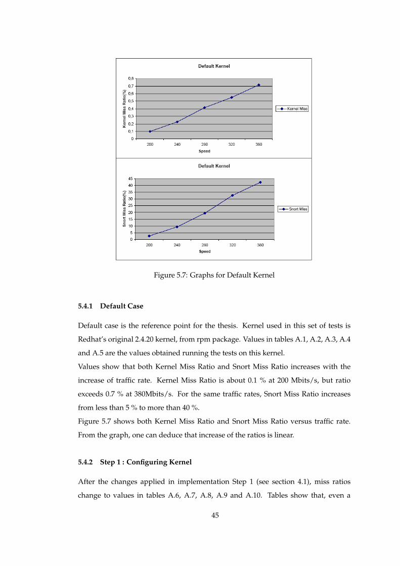
Figure 5.7: Graphs for Default Kernel
5.4.1 Default Case
Default case is the reference point for the thesis. Kernel used in this set of tests is
Redhat’s original 2.4.20 kernel, from rpm package. Values in tables A.1, A.2, A.3, A.4
and A.5 are the values obtained running the tests on this kernel.
Values show that both Kernel Miss Ratio and Snort Miss Ratio increases with the
increase of traffic rate. Kernel Miss Ratio is about 0.1 % at 200 Mbits/s, but ratio
exceeds 0.7 % at 380Mbits/s. For the same traffic rates, Snort Miss Ratio increases
from less than 5 % to more than 40 %.
Figure 5.7 shows both Kernel Miss Ratio and Snort Miss Ratio versus traffic rate.
From the graph, one can deduce that increase of the ratios is linear.
5.4.2 Step 1 : Configuring Kernel
After the changes applied in implementation Step 1 (see section 4.1), miss ratios
change to values in tables A.6, A.7, A.8, A.9 and A.10. Tables show that, even a
45

good kernel configuration halves the miss ratio.
This performance improvement depends on many different aspects. Kernel, with
many supports, has to do a lot of checking the existance of the feature. For example,
socket filtering. This feature directly related to networking performance. The aim
of this thesis is to transfer the packet received to application as soon as possible, not
selective transfer. Thus, this feature is not needed. Kernel, supporting socket filters,
at least checks whether a filter is attached to the socket. This means loss of time and
CPU cycles. Many other supports, even not related to networking code, at least gen-
erate interrupts and steal CPU cycles.
Some features like parallel port support requires polling of the devices. If kernel does
not have support for such features, polling is not needed. This means saving CPU
cycles. One another save with small kernel is the memory. Memory saved from ker-
nel size, is used for the application.
Kernel Miss Ratios and Snort Miss Ratios obtained by running snort with newly con-
figured kernel are skecthed in figure 5.8. Graph also includes the values of the default
for comparison. It can be seen that Snort Miss Ratio decreases about the half when
compared to the default values, and Kernel Miss Ratio is about 75 % of the default’s.
5.4.3 Step 2 : Modifying AF PACKET Receive Functions
Implementation Step 2 includes little modifications to packet receive function for
packet socket type sockets (see section 4.2). Modifications depend on known feature
and they are algorithmic modifications. Test results can be seen in tables A.11, A.12,
A.13, A.14 and A.15 for speeds 200, 240, 280, 320 and 380 Mbits/s respectively.
Snort Miss Ratios are almost same with the previous step. But at high speeds new
ratios are a little better. This is due to Kernel Miss. At high traffic rates, Kernel Miss
Ratio difference is not greater between this step and previous step. Graph in figure
5.9 depicts the picture for both Snort and Kernel Miss Ratios.
5.4.4 Step 3 : Omitting IP Processing
Every packet is first sent to sockets that are of type ETH P ALL. Then, they are deliv-
ered to the corresponding protocol handler. At this step, since second branch is cut
46
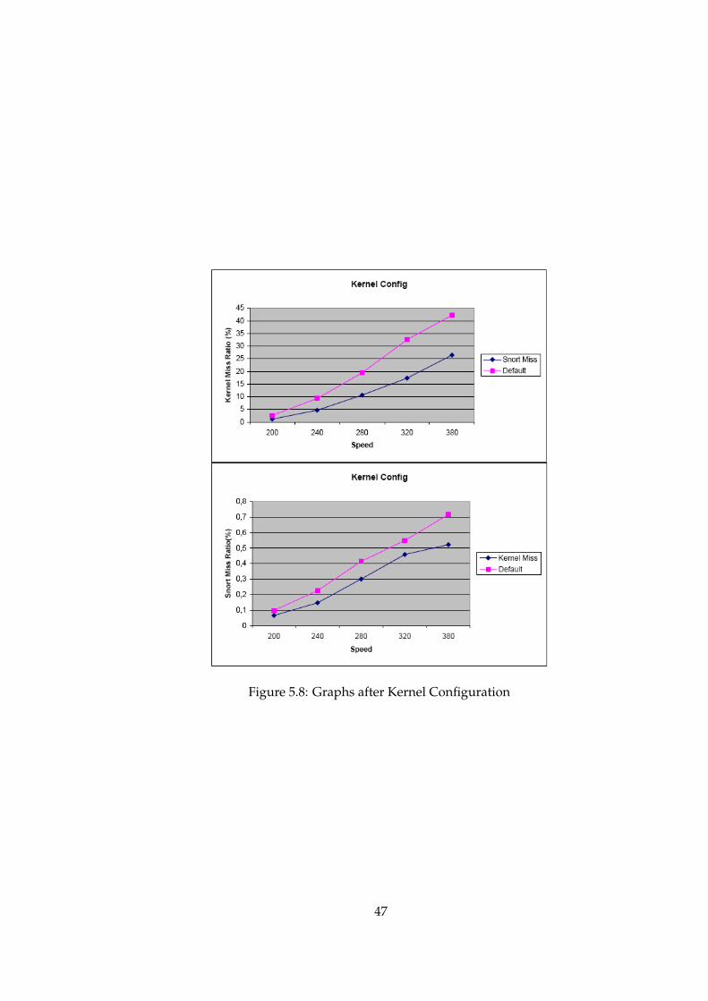
Figure 5.8: Graphs after Kernel Configuration
47

Figure 5.9: Graphs after Modifying AF PACKET Receive Functions
48
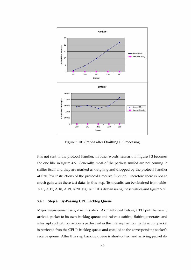
Figure 5.10: Graphs after Omitting IP Processing
it is not sent to the protocol handler. In other words, scenario in figure 3.3 becomes
the one like in figure 4.5. Generally, most of the packets sniffed are not coming to
sniffer itself and they are marked as outgoing and dropped by the protocol handler
at first few instructions of the protocol’s receive function. Therefore there is not so
much gain with these test datas in this step. Test results can be obtained from tables
A.16, A.17, A.18, A.19, A.20. Figure 5.10 is drawn using these values and figure 5.8.
5.4.5 Step 4 : By-Passing CPU Backlog Queue
Major improvement is got in this step. As mentioned before, CPU put the newly
arrived packet to its own backlog queue and raises a softirq. Softirq generates and
interrupt and netif rx action is performed as the interrupt action. In the action packet
is retrieved fron the CPU’s backlog queue and entailed to the corresponding socket’s
receive queue. After this step backlog queue is short-cutted and arriving packet di-
49
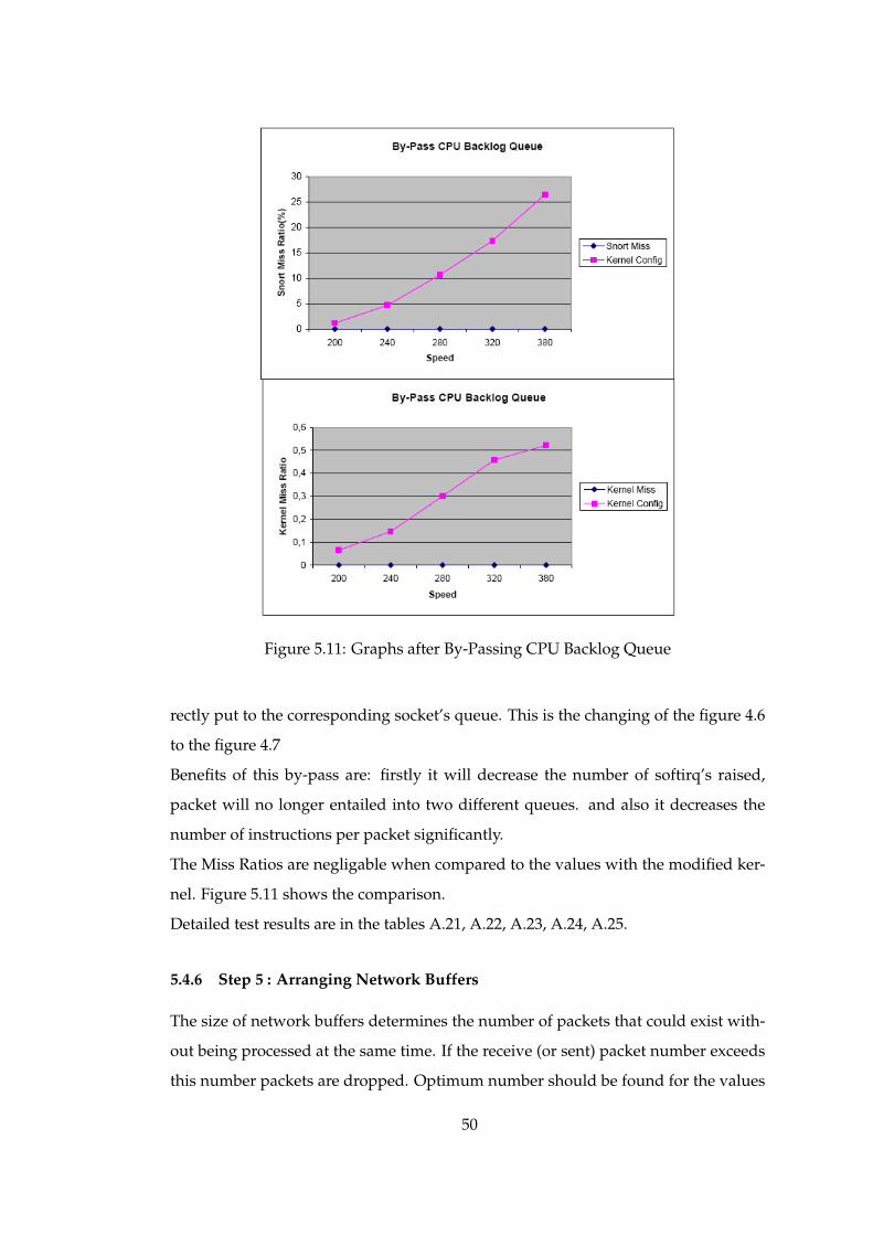
Figure 5.11: Graphs after By-Passing CPU Backlog Queue
rectly put to the corresponding socket’s queue. This is the changing of the figure 4.6
to the figure 4.7
Benefits of this by-pass are: firstly it will decrease the number of softirq’s raised,
packet will no longer entailed into two different queues. and also it decreases the
number of instructions per packet significantly.
The Miss Ratios are negligable when compared to the values with the modified ker-
nel. Figure 5.11 shows the comparison.
Detailed test results are in the tables A.21, A.22, A.23, A.24, A.25.
5.4.6 Step 5 : Arranging Network Buffers
The size of network buffers determines the number of packets that could exist with-
out being processed at the same time. If the receive (or sent) packet number exceeds
this number packets are dropped. Optimum number should be found for the values
50

Figure 5.12: Graphs after Arranging Network Buffers
of macros SOCK MIN SNDBUF and SOCK MIN RCVBUF. Putting just very large
values to those macros is not come up with wonderful results. Because it makes ker-
nel larger, it may prevent some other functions.
Setting SOCK MIN RCVBUF to 4096 and SOCK MIN SNDBUF to 256 slightly in-
creased the network performance. rate of increase is higher at higher traffic rates.
Values, obtained at each run on modified kernel, can be found in tables A.26, A.27,
A.27, A.29, A.30. Graphs in figure 5.12 are plotted by using these values.
5.4.7 Step 6 : Modifying Ethernet Driver
Ethernet Driver is the first touch point of the packet with the kernel source. Any
decrease in number of instructions will affect overall system performance directly.
The driver of 3com EtherXL PCI is written in a very optimized way. Only debugging
information and some conditional checks could be removed from the code. Even
51

Figure 5.13: Graphs after Modifying Ethernet Driver
this small modification affects the miss ratios. Tables A.31, A.32, A.33, A.34 and A.35
shows the values obtained from the test runs. Snort Miss Ratio vs Speed and Kernel
Miss Ratio vs Speed graphs in figure 5.13 are drawn based on these values. Although
it seems there is an increase in Snort Miss Ratio, this is because Kernel Miss Ratio is
very much smaller than configured kernel. Small Kernel Miss Ratio means more
packets received. Although snort analyses approximately same number of packets,
miss ratio is less in this step, at lower traffic rates. However at higher traffic rates,
snort could analysed more packets than the configured kernel. This again led to
decrease in Snort Miss Ratio. 5.7, 5.8, 5.9, 5.10, 5.11, 5.12 and 5.13, to allow good
comparison of the implementation steps. At each step packet lost ratio decreases, i.e
overall system performance increases.
52
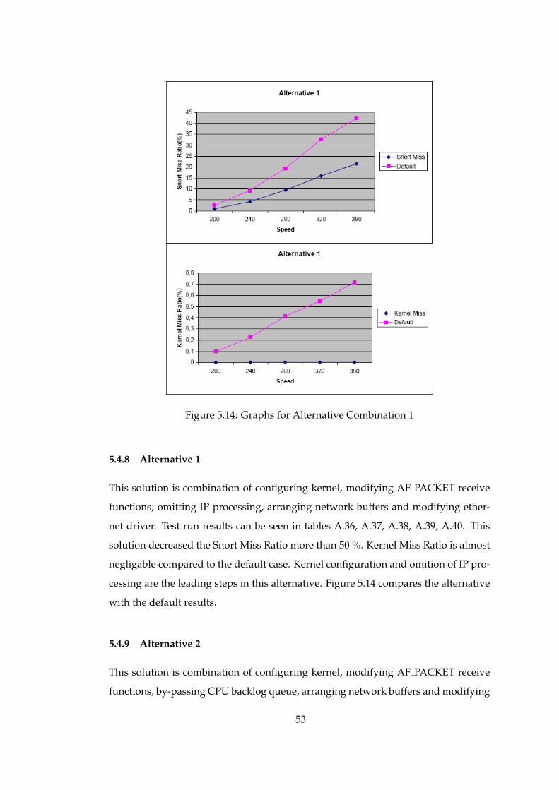
Figure 5.14: Graphs for Alternative Combination 1
5.4.8 Alternative 1
This solution is combination of configuring kernel, modifying AF PACKET receive
functions, omitting IP processing, arranging network buffers and modifying ether-
net driver. Test run results can be seen in tables A.36, A.37, A.38, A.39, A.40. This
solution decreased the Snort Miss Ratio more than 50 %. Kernel Miss Ratio is almost
negligable compared to the default case. Kernel configuration and omition of IP pro-
cessing are the leading steps in this alternative. Figure 5.14 compares the alternative
with the default results.
5.4.9 Alternative 2
This solution is combination of configuring kernel, modifying AF PACKET receive
functions, by-passing CPU backlog queue, arranging network buffers and modifying
53

Figure 5.15: Graphs for Alternative Combination 2
ethernet driver. Test run results can be seen in tables A.41, A.42, A.43, A.44, A.45.
This solution provided significant decrease the Snort Miss Ratio. Kernel Miss Ratio
is again almost negligable when compared to the default case. Leading step for this
alternative is by-passing CPU backlog queue. Figure 5.15 compares the alternative
with the default results.
54

CHAPTER 6
CONCLUSION AND FUTURE WORK
Sniffers works fine with low traffic loads, but as the technology grew, life became
difficult for sniffers. Network gets higher than the value that a sniffer can cope with.
Many researchers carry out noticeable efforts on this issue. Some efforts are field
specific like GAMMA [18][19]. Most of other efforts are carried out by researches
working in industry. They claim to find effective solution to the problem but they do
not give technical details of what they have done, i.e. they do not give out the know-
how. Another industrial approach is to produce better hardware, but as in most cases
hardware solution is very expensive one.
In this thesis, a free and generic approach is proposed to get better performance in
sniffing even under high network loads. With this thesis an open, free and non field-
specific approach is achieved for the goal via kernel modifications and modification
to the network interface card. This approach is not a complete solution to the prob-
lem like all other approaches. Because there will always be a bottleneck network
traffic rate that devices can cope with.
Linux is most popular and known operating system when free and open source is
talked about. Documentation for Linux kernel is also better than most of other op-
erating systems. Although this helps so much in modifying kernel, understanding
the kernel code fully was not easy. Strategy was minimizing the path a packet trav-
els. Using mmap to eliminate unnecessary memory copies, not allowing the packet
traversing unnecessary branches in the Linux networking code and removing mid-
dle queues are parts of this strategy.
55

First, kernel is configured to use mmap and unnecessary supports are removed from
configuration. pcap based sniffers uses special socket type called PACKET SOCKET.
Support for this type of sockets is also added. Then some check about known issues
eliminated in receive function.
Packet need not to traverse the protocol layers like IP, if it is only used for sniffing. It
is just sent to related PACKET SOCKET type socket’s queue. An other issue is that
CPU forms a backlog queue to which it collects all incoming packets to itself. De-
livery to related queues are done later. CPU is made to deliver directly to related
queues, i.e. backlog queue is by-passed. The size of network buffers is an other bot-
tleneck for network transfers. Since sniffers deal with receiving receive buffer size
is increased. Sending is not so important, therefore to keep kernel size small send
buffer size is decreased. Finally; driver of the network interface card is processed.
Actually, NIC driver,3Com Ether XL PCI, was a very optimized one. Not so much
thing to do with it. Disabling debugging and some conditional check elimination is
done.
Proposed work is mostly machine and platform independent except the first and last
steps. In the first step correct network driver has to be chosen according to systems
network interface card, and at the last step driver modification is directly dependent
to the network interface card again. All other steps are platform independent. This
is an advantage of the system.
Removing unnecessary supports and features, and configuring the kernel according
to the system decreased the packet lost ratios for Snort and the kernel. Proper con-
figuration of the kernel provided decrease in the kernel code by means of instruction
count and size. Test results have shown that gain is about 50 % according to the
baseline system. In Step 2 (Modifying AF PACKET Receive Functions) of the imple-
mentation little modifications to networking code is done to reduce the number of
instructions per packet. Just a small amount of performance gain is achieved after
this step.
Omitting IP processing is one of the steps that was expected to increase system per-
formance. After the test results, it was seen that there was not that much improve-
ment. Most probable reason for this is the characteristics of the test data. Test data
almost does not contain packets whose destination is the sniffing PC. With data con-
56
taining more such packets may give better results. The majority performance in-
crease is achieved in forth step (By-Passing CPU Backlog Queue). By-passing CPU
backlog queue shorten the path of the packet captured from the network. Packet lost
ratios decreased to the values that may be ignored for both Snort and the kernel.
Network buffers for packet receiving were increased to store more received pack-
ets not to drop them. The system was not affected by the arrangement of network
buffers, however little increase was observed. One of the modifications targeting to
decrease number of instructions per packet was modifying the NIC driver of the ker-
nel. After the modifications while packets lost by kernel is decreasing, packets lost
by Snort is increased.
Two alternative combinations of these have been formed after implementing each
of the steps above. First alternative was composed of kernel configuration, packet
receive function modifications, IP processing omition, network buffer arrangement
and NIC driver modification. The overall system performance was doubled. In the
second alternative combination IP processing omition was replaced with by-passing
CPU backlog queue. Newly written code for by-passing CPU backlog queue, in-
herently includes the omition of IP processing. Overall results for this alternative
was just a bit better than the results obtained after step 4 (By-Passing CPU Backlog
Queue).
There is still some work may be performed on improving kernel performance. The
issues can be exported to the gigabit networks with a little effort. 3Com NIC’s driver
for Linux is an interrupt-based driver. Using polling instead of interrupt mechanism
may bring some more improvement to overall system performance.
One other way is developing a new operating system considering only sniffing issues
in mind. Though this is a hard work to do.
An other future work may be dealing with sniffer based applications individually,
not the kernel itself.
57
REFERENCES
[1] Snort, “The open source network intrusion detection system,”, http://www.snort.org .
[2] M. Eichin and J. Rochlis, “With Microscope and Tweezers: An Analysis of theInterent Virus of November 1988,” in Proceedings of the 1989 IEEE Symposium onResearch in Security and Privacy, 1989.
[3] S. Kumar, Classification and Detection of Computer Intrusions. PhD thesis, PurdueUniversity, August 1995.
[4] M. Baker and H. Ong, “A quantitative study on the communication perfor-mance of myrinet network interfaces,” March 15, 2002.
[5] T. Von Eicken, A. Basu, V. Buch, and W. Vogels, “U-NET: A User Level NetworkInterface for Parallel and Distributed Computing,” in Proceeding of the Interna-tional Conference on Supercomputing’95, 1995.
[6] S. Pakin, M. Lauria, A. Chien, “High Performance Messaging on Workstation:Illinois Fast Message (FM) for Myrinet,” in Proceeding of the International Confer-ence on Supercomputing’95, 1995.
[7] T. Von Eicken, D. E. Culler, S. C. Goldstein, and K. E. Schauser, “Active Mes-sages: A Mechanism for Integrated Communication and Computation,” in In-ternational Symposium on Computer Architecture, 1992.
[8] Myricom Inc., “The GM Message Passing System,” 2000.
[9] L. Torvalds, “The linux kernel,”, http://www.kernel.org .
[10] N. Boden, D. Cohen, and R. Felderman, “Myrinet: a gigabit per second local-area network,” in IEEE Micro 14(1), February 1994.
[11] I. Sun Microsystems, “Solaris,”, http://www.sun.com .
[12] FreeBSD, “The FreeBSD Project,”, http://www.freebsd.org .
[13] H.-Y. Kim, “Improving Networking Server Performance with ProgrammableNetwork Interfaces,” Master’s thesis, Rice University, 2003.
[14] Intel Network Interface Cards, “Intel Corporation,”, http://www.intel.com.
58

[15] G. Memik, and W.H. Mangione-Smith, “Specialized Hardware for Deep Net-work Packet Filtering,” in Proceeedings of FPL 2002, Montpellier, France, Septem-ber 2002.
[16] L. Deri, “Passively Monitoring Networks at Gigabit Speeds Using CommodityHardware and Open Source Software,” 2003.
[17] J. R. C. Zubin D. Dittia, Guru M. Parulkar, “The APIC Approach to High Per-formance Network Interface Design: Protected DMA and Other Techniques,”2003.
[18] G. Ciaccio, M. Ehlert, and B. Schnor, “Exploiting Gigabit Ethernet Capacity forCluster Applications,” in Proceedings of 27th Annual IEEE Conference on LocalComputer Networks (LCN 2002), Tampa, FL, USA. LCM, pp. 669–678, November2002.
[19] G. Chiola, G. Ciaccio, L. V. Mancini, and P. Rotondo, “GAMMA on DEC 2114xwith Efficient Flow Control,”, citeseer.nj.nec.com/210324.html , 2003.
[20] NFR, “Network Flight Recorder,”, http://www.nfrsecurity.com .
[21] R. Graham, “Sniffing (network wiretap, sniffer) FAQ v03.3,” 2000,http://www.robertgraham.com/pubs/sniffing-faq.html.
[22] F. N. Services, “Using a Network Sniffer,”, http://www.flgnetworking.com/brief6.html , 2003.
[23] D. Magers, “Packet Sniffing: An Integral Part of Network Defense,” 2002.
[24] S. E. Smaha, “Haystack: An Intrusion Detection System,” in Fourth AerospaceComputer Security Applications Conference, pp. 37–44, December 1988.
[25] S. F. Steven A. Hofmeyr and A. Somayaji, “Lightweight intrusion detection fornetworked operating systems,” CHECK.
[26] T. F. Lunt, A. Tamaru, F. Gilham, R. Jagannathan, P. G. Neumann, H. S. Javitz,A. Valdes and T. D. Garvey, “A Real-Time Intrusion Detection Expert System(IDES),” final technical report, Computer Science Laboratory, SRI International,February 1992.
[27] J. Olson, “SNARE:System iNtrusion Analysis and Reporting Environment,”,http://www.linuxsecurity.com/articles/intrusion_detection_article-4140.%html .
[28] GrSecurity, “GrSecurity,”, http://www.grsecurity.net .
[29] CyberSafe Ltd., “CyberSafe,”, http://www.cybersafe.ltd.uk .
[30] G. Vigna and R. A. Kemmerer, “Netstat: A network-based intrusion detectionsystem,” Journal of Computer Security, vol. 7, no. 1, 1999.
[31] M. Roesch, “Snort - Light Weight Intrusion Detection for Networks,” in Proceed-ings of the 13th LISA Conference of USENIX Association, 1999.
59
[32] B. Dayıoglu, “Use of Passive Network Mapping to Enhance Network Intru-sion Detection,” Master’s thesis, Department of Computer Engineering, METU,2001.
[33] M. Roesch, Snort Users Manual, snort release: 1.9.x ed., 26th April 2002.
[34] A. S. Tanenbaum, Modern Operating Systems, ch. 1, pp. 1–25. Prentice-Hall Inte-national, Inc, 1992.
[35] D. A. Rusling, The Linux Kernel, ch. 8, pp. 95–97. Linux Documentation Project,1999.
[36] J. A. Orr and D. Cyganski, “Information Engineering Across the Professions,A New Course for Students Outside EE,” in Proceedings of Frontier in EducationConference, Tempe, Arizona, Nov. 4-7, 1998.
[37] L. Besaw, “Berkeley UNIX System Calls and Interprocess Communication,” Jan-uary, 1987.
[38] M. Rio, T. Kelly, M. Goutelle, R. Hughes-Jones, and J.-P. Martin-Flatin, “A Mapof the Networking Code in Linux Kernel 2.4.20,” draft, DataTag project (IST-2001-32459), September, 2003.
[39] G. Insolvibile, “Kernel korner: Inside the Linux packet filter, part II,” Linux Jour-nal, vol. 2002, no. 95, p. 7, 2002.
[40] TCPReplay, “Data dump tool,”, http://www.tcpdump.org .
60

APPENDIX A
Test Runs
A.1 Test Runs with default Kernel
Table A.1: Results for Default at 200 Mbits/s
Run Packets Sent Packet Received Snort Analyzed1 14648887 14634732 142798672 14664568 14650837 142813703 14666527 14650142 142551684 14657310 14644243 142267335 14660572 14646012 14261282
Table A.2: Results for Default at 240 Mbits/s
Run Packets Sent Packet Received Snort Analyzed1 14456449 14426116 131200212 14472974 14442726 131038063 14488042 14450888 130642864 14493444 14458846 130802875 14486392 14455194 13130704
61

Table A.3: Results for Default at 280 Mbits/s
Run Packets Sent Packet Received Snort Analyzed1 14148581 14088012 113336982 14143582 14087795 113601543 14149642 14090469 113728084 14151269 14089733 113357845 14156283 14100327 11350778
Table A.4: Results for Default at 320 Mbits/s
Run Packets Sent Packet Received Snort Analyzed1 13373923 13300636 90631852 13370847 13299500 90063373 13382256 13305622 89181844 13382222 13306901 89659835 13377507 13306701 8890558
Table A.5: Results for Default at 380 Mbits/s
Run Packets Sent Packet Received Snort Analyzed1 11435153 11348188 68048972 11435183 11354567 68417623 11447357 11366755 69863904 11416085 11336690 68961905 11440568 11358222 5238604
62
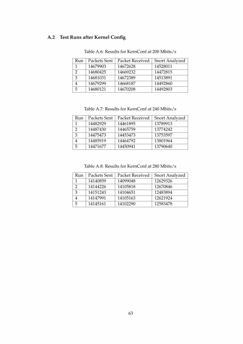
A.2 Test Runs after Kernel Config
Table A.6: Results for KernConf at 200 Mbits/s
Run Packets Sent Packet Received Snort Analyzed1 14679903 14672628 145280112 14680425 14669232 144728153 14681031 14672389 145138914 14679299 14668187 144928605 14680121 14670208 14492803
Table A.7: Results for KernConf at 240 Mbits/s
Run Packets Sent Packet Received Snort Analyzed1 14482929 14461895 137899132 14487430 14465759 137742423 14475473 14453473 137535974 14485919 14464792 138019645 14471677 14450941 13790640
Table A.8: Results for KernConf at 280 Mbits/s
Run Packets Sent Packet Received Snort Analyzed1 14140859 14099048 126293262 14144226 14105818 126708463 14151243 14104651 124838944 14147991 14105163 126219245 14145161 14102290 12583478
63

Table A.9: Results for KernConf at 320 Mbits/s
Run Packets Sent Packet Received Snort Analyzed1 13362587 13303915 110063482 13368397 13308939 110708623 13345955 13279101 109123554 13369457 13309002 109747255 13371587 13310430 10987267
Table A.10: Results for KernConf at 380 Mbits/s
Run Packets Sent Packet Received Snort Analyzed1 11419833 11355352 87922952 11430335 11371813 88199363 11452539 11388802 87957084 11441791 11386773 89100435 11435470 11378527 6496228
A.3 Test Runs after Modifying af packet.c
Table A.11: Results for AF PACKET at 200 Mbits/s
Run Packets Sent Packet Received Snort Analyzed1 14617195 14616879 144666962 14671077 14670873 144926283 14672904 14672689 145098464 14674152 14673944 145097505 14672201 14671805 14519842
64

Table A.12: Results for AF PACKET at 240 Mbits/s
Run Packets Sent Packet Received Snort Analyzed1 14467626 14467400 137884942 14467926 14467757 138101823 14473507 14473293 138125804 14462059 14461920 138184145 14452842 14452708 13708736
Table A.13: Results for AF PACKET at 280 Mbits/s
Run Packets Sent Packet Received Snort Analyzed1 14129897 14129781 126564682 14142394 14142278 126722693 14128651 14128573 124176474 14155796 14155708 126718235 14135797 14135664 12713515
Table A.14: Results for AF PACKET at 320 Mbits/s
Run Packets Sent Packet Received Snort Analyzed1 13399392 13398737 110776712 13375086 13374947 109157573 13400650 13400529 110813684 13417281 13417138 110997845 13393475 13393354 11051776
65

Table A.15: Results for AF PACKET at 380 Mbits/s
Run Packets Sent Packet Received Snort Analyzed1 11488069 11487973 88725822 11505199 11505062 88436753 11498414 11498277 89113074 11487908 11487805 88846485 11470949 11470813 8925665
A.4 Test Runs after Omitting IP Processing
Table A.16: Results for OmitIP at 200 Mbits/s
Run Packets Sent Packet Received Snort Analyzed1 14677937 14677774 145173802 14673332 14673148 145170613 14680619 14680464 145289354 14678339 14678122 145303115 14672917 14672603 14533472
Table A.17: Results for OmitIP at 240 Mbits/s
Run Packets Sent Packet Received Snort Analyzed1 14485497 14485297 138805072 14478477 14478161 138767353 14477048 14476837 138651704 14481886 14481714 138709615 14470257 14470059 13713345
66

Table A.18: Results for OmitIP at 280 Mbits/s
Run Packets Sent Packet Received Snort Analyzed1 14145941 14145750 127186192 14153847 14153674 127705003 14152973 14152798 127542354 14141896 14141708 127623055 14135929 14135748 12776674
Table A.19: Results for OmitIP at 320 Mbits/s
Run Packets Sent Packet Received Snort Analyzed1 13411860 13411691 112308122 13392435 13392244 112249343 13393598 13393381 112504574 13385979 13385766 112172435 13391727 13391524 11239309
Table A.20: Results for OmitIP at 380 Mbits/s
Run Packets Sent Packet Received Snort Analyzed1 11505787 11505601 90249902 11504088 11503917 89600693 11482676 11482468 90106904 11489215 11488995 89245875 11504324 11503875 9004779
67
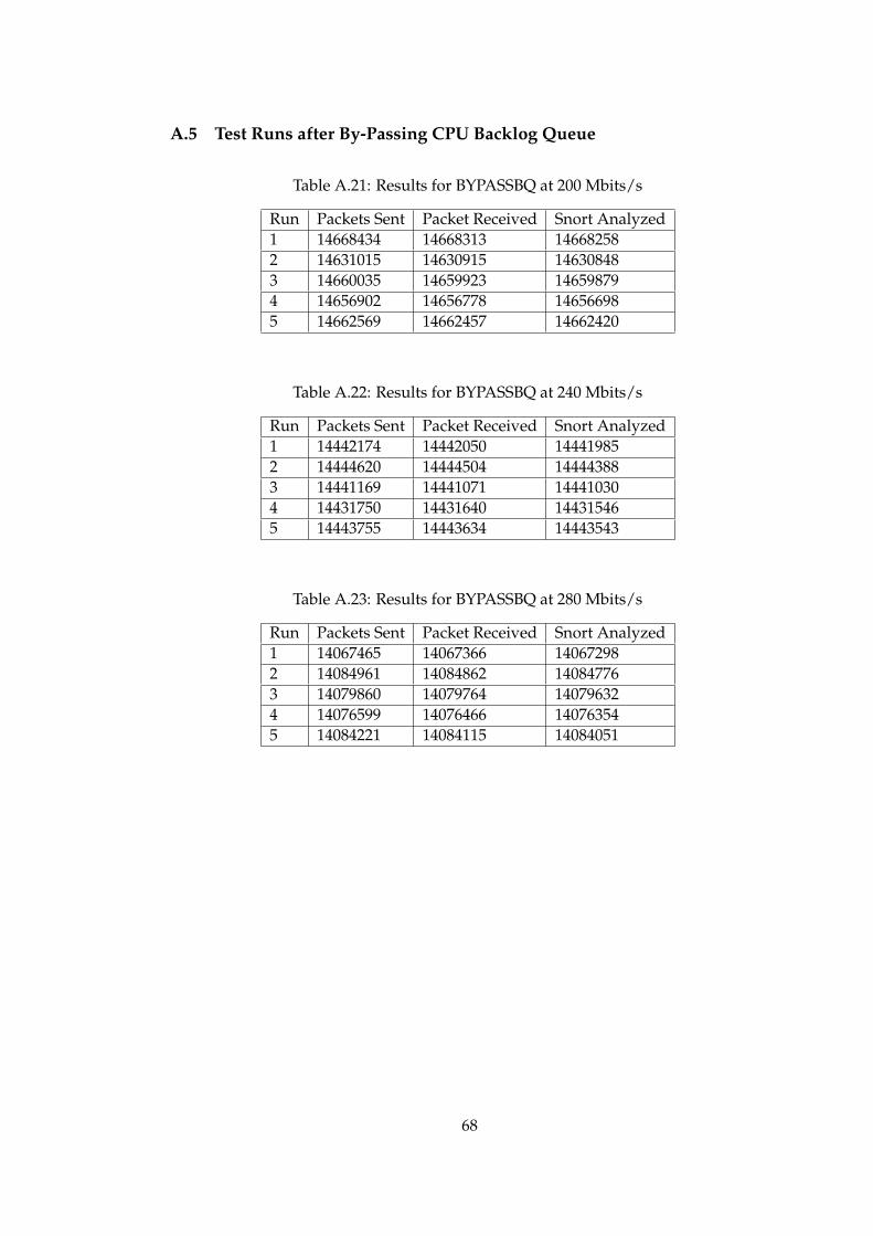
A.5 Test Runs after By-Passing CPU Backlog Queue
Table A.21: Results for BYPASSBQ at 200 Mbits/s
Run Packets Sent Packet Received Snort Analyzed1 14668434 14668313 146682582 14631015 14630915 146308483 14660035 14659923 146598794 14656902 14656778 146566985 14662569 14662457 14662420
Table A.22: Results for BYPASSBQ at 240 Mbits/s
Run Packets Sent Packet Received Snort Analyzed1 14442174 14442050 144419852 14444620 14444504 144443883 14441169 14441071 144410304 14431750 14431640 144315465 14443755 14443634 14443543
Table A.23: Results for BYPASSBQ at 280 Mbits/s
Run Packets Sent Packet Received Snort Analyzed1 14067465 14067366 140672982 14084961 14084862 140847763 14079860 14079764 140796324 14076599 14076466 140763545 14084221 14084115 14084051
68

Table A.24: Results for BYPASSBQ at 320 Mbits/s
Run Packets Sent Packet Received Snort Analyzed1 13296924 13296842 132967232 13328052 13327943 133278553 13320945 13320831 133207334 13316128 13316023 133159025 13323897 13323793 13323664
Table A.25: Results for BYPASSBQ at 380 Mbits/s
Run Packets Sent Packet Received Snort Analyzed1 11393589 11393475 113934392 11432921 11432840 114327213 11397400 11397303 113971604 11398851 11398751 113986435 11425953 11425821 11425740
A.6 Test Runs after Arranging Network Buffers
Table A.26: Results for NETBUF at 200 Mbits/s
Run Packets Sent Packet Received Snort Analyzed1 14663391 14663193 145232662 14667009 14666775 145140203 14663658 14663426 145280214 14659338 14659059 145273385 14666751 14666506 14525750
69

Table A.27: Results for NETBUF at 240 Mbits/s
Run Packets Sent Packet Received Snort Analyzed1 14431705 14431389 137982622 14441571 14441016 137493843 14454725 14454270 137897984 14449822 14449585 137764095 14458160 14457936 13782456
Table A.28: Results for NETBUF at 280 Mbits/s
Run Packets Sent Packet Received Snort Analyzed1 14108641 14108458 126800662 14122659 14122355 127002333 14126611 14126172 126561184 14112913 14112467 126794375 14126472 14126032 12690276
Table A.29: Results for NETBUF at 320 Mbits/s
Run Packets Sent Packet Received Snort Analyzed1 13356564 13356059 111393752 13352198 13351612 110561713 13348551 13348030 111081634 13332548 13332114 111264025 13348922 13348456 11118115
70

Table A.30: Results for NETBUF at 380 Mbits/s
Run Packets Sent Packet Received Snort Analyzed1 11439663 11439265 88648922 11467424 11466997 89344813 11460031 11459616 88173124 11435357 11435175 88317005 11462447 11462302 8765980
A.7 Test Runs after Modifying Network Driver
Table A.31: Results for DRIVER at 200 Mbits/s
Run Packets Sent Packet Received Snort Analyzed1 14668741 14668659 145025452 14672185 14672115 145215953 14672940 14672867 144852544 14672967 14672868 144703335 14674188 14674126 14511152
Table A.32: Results for DRIVER at 240 Mbits/s
Run Packets Sent Packet Received Snort Analyzed1 14463421 14463337 137639612 14470767 14470682 137214463 14460437 14460334 135788204 14463090 14462991 137460635 14468574 14468486 13733497
71

Table A.33: Results for DRIVER at 280 Mbits/s
Run Packets Sent Packet Received Snort Analyzed1 14126834 14126752 125989102 14132597 14132514 126020483 14119502 14119410 125981274 14127563 14127498 126107965 14130993 14130891 12587825
Table A.34: Results for DRIVER at 320 Mbits/s
Run Packets Sent Packet Received Snort Analyzed1 13377551 13377484 108168192 13383644 13383559 109512643 13383192 13383102 109657324 13372788 13372704 109245335 13362457 13362399 10982439
Table A.35: Results for DRIVER at 380 Mbits/s
Run Packets Sent Packet Received Snort Analyzed1 11448176 11448089 86772382 11480413 11480337 87349343 11470595 11470511 86512844 11472506 11472431 87426055 11468073 11467998 8670965
72

A.8 Test Runs after Alternative 1
Table A.36: Results for ALTERNATIVE1 at 200 Mbits/s
Run Packets Sent Packet Received Snort Analyzed1 14671308 14671210 145518422 14673415 14673333 145314993 14674799 14674725 145423304 14674085 14674003 145306585 14668843 14668773 14518449
Table A.37: Results for ALTERNATIVE1 at 240 Mbits/s
Run Packets Sent Packet Received Snort Analyzed1 14452059 14451970 138499822 14463707 14463617 138532263 14450721 14450611 138154494 14458128 14458029 138363205 14463045 14462926 13842775
Table A.38: Results for ALTERNATIVE1 at 280 Mbits/s
Run Packets Sent Packet Received Snort Analyzed1 14118523 14118400 127367902 14137804 14137662 127629033 14120540 14120301 127700894 14141164 14140898 127602905 14128068 14127898 12786918
73
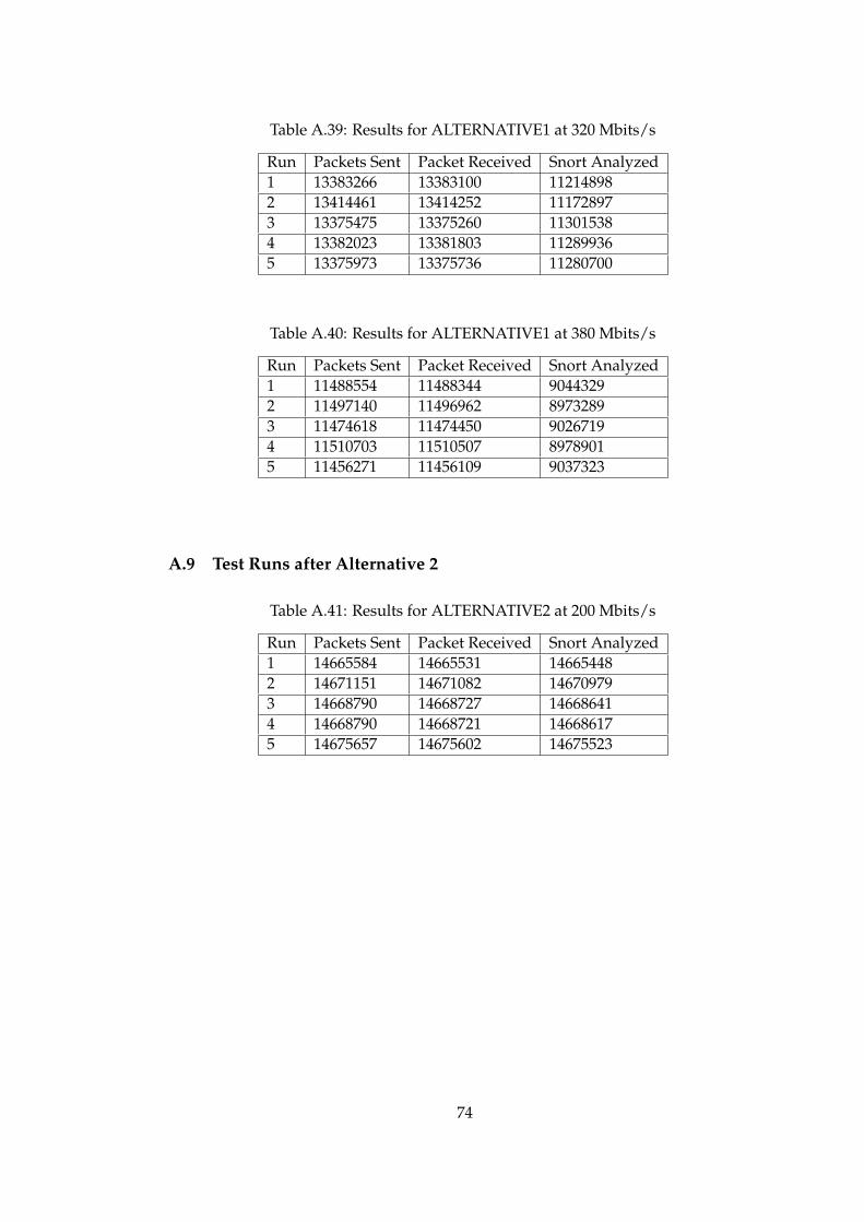
Table A.39: Results for ALTERNATIVE1 at 320 Mbits/s
Run Packets Sent Packet Received Snort Analyzed1 13383266 13383100 112148982 13414461 13414252 111728973 13375475 13375260 113015384 13382023 13381803 112899365 13375973 13375736 11280700
Table A.40: Results for ALTERNATIVE1 at 380 Mbits/s
Run Packets Sent Packet Received Snort Analyzed1 11488554 11488344 90443292 11497140 11496962 89732893 11474618 11474450 90267194 11510703 11510507 89789015 11456271 11456109 9037323
A.9 Test Runs after Alternative 2
Table A.41: Results for ALTERNATIVE2 at 200 Mbits/s
Run Packets Sent Packet Received Snort Analyzed1 14665584 14665531 146654482 14671151 14671082 146709793 14668790 14668727 146686414 14668790 14668721 146686175 14675657 14675602 14675523
74
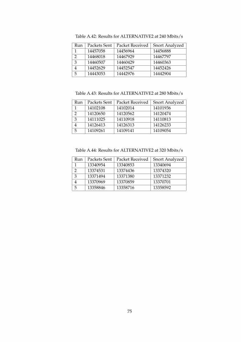
Table A.42: Results for ALTERNATIVE2 at 240 Mbits/s
Run Packets Sent Packet Received Snort Analyzed1 14457058 14456964 144568882 14468018 14467929 144677973 14460507 14460429 144603634 14452629 14452547 144524265 14443053 14442976 14442904
Table A.43: Results for ALTERNATIVE2 at 280 Mbits/s
Run Packets Sent Packet Received Snort Analyzed1 14102108 14102014 141019362 14120650 14120562 141204743 14111025 14110918 141108134 14126413 14126313 141262335 14109261 14109141 14109054
Table A.44: Results for ALTERNATIVE2 at 320 Mbits/s
Run Packets Sent Packet Received Snort Analyzed1 13340954 13340853 133406942 13374531 13374436 133743203 13371494 13371380 133712324 13370969 13370859 133707015 13358846 13358716 13358592
75

Table A.45: Results for ALTERNATIVE2 at 380 Mbits/s
Run Packets Sent Packet Received Snort Analyzed1 11456087 11455995 114559372 11463669 11463540 114634813 11458331 11458199 114580764 11479022 11478884 114787865 11472670 11472559 11472471
76