Embed Size (px)
Citation preview

Improvement of Simultaneous 5-Axis ControlledMachining Accuracy by CL-Data Modification
Paper:
Improvement of Simultaneous 5-Axis ControlledMachining Accuracy by CL-Data Modification
Ryuta Sato∗,†, Kiichi Morishita∗, Isamu Nishida∗, Keiichi Shirase∗,Masanobu Hasegawa∗∗, Akira Saito∗∗, and Takayuki Iwasaki∗∗
∗Department of Mechanical Engineering, Kobe University1-1 Rokko-dai, Nada, Kobe 657-8501, Japan
†Corresponding author, E-mail: [email protected]∗∗Production Engineering Center, IHI Corporation, Yokohama, Japan
[Received February 26, 2019; accepted June 29, 2019]
As the motion accuracy of 5-axis machining centersdirectly influences the geometrical shape accuracy ofthe machined workpieces, accuracy enhancement ofthe 5-axis machining centers is strongly needed. Toimprove the shape accuracy during the machining bya 5-axis machine tool, a method that modifies theCL-data based on the motion trajectory errors nor-mal to the machined surface at each command pointhas been proposed. In this study, the proposed methodis applied to simultaneous 5-axis controlled machiningto improve motion accuracy. A normal vector calcula-tion method for the simultaneous 5-axis controlled mo-tion is newly proposed, and the compensation methodis applied to turbine blade machining by 5-axis con-trolled motion. Measurement tests of the cutting mo-tion for blade shape machining by a ball-end mill werecarried out with a different control mode of NC. TheCL-data for the machining tool path was also modifiedbased on the calculated trajectory of the tool centerpoint. Experimental results reveal that the feed speedand machining accuracy significantly depend on thecontrol mode of NC, and that the shape accuracy canbe improved by applying the proposed compensationmethod without any decrease in motion speed.
Keywords: 5-axis machine tool, 5-axis controlled mo-tion, CL-data, motion accuracy, compensation
1. Introduction
As the motion accuracies of numerical control (NC)machine tools influences the machined surface of the ma-chined pieces, it is important to improve them. 5-axis ma-chining centers, which can control both the relative posi-tion and angle between tool and workpiece, are now oftenused for the machining of complex shaped parts [1, 2].It has been established that the motion accuracy of the5-axis machining centers deteriorates owing to several er-ror sources. For example, the rotary axes of the 5-axismachining centers have positional and angular errors of
the rotational centers called geometrical errors [3]. As itis known that the geometrical errors deteriorate the geo-metrical accuracy of the machined parts, several studieshave been carried out to identify and compensate for theerrors [4]. A machining test for evaluating the geometricerrors has also been proposed [5–7]. The geometrical er-rors can be compensated for in the latest 5-axis machiningcenters by using compensation functions.
The dynamic synchronous errors between the transla-tional and rotary axes also need to be considered. The dy-namic synchronous errors during the simultaneous multi-axis motions of the translational and rotary axes havebeen investigated [8, 9]. It was also confirmed that thedynamic synchronous errors during simultaneous 5-axismotion deteriorate the geometric accuracy of the ma-chined shape [10]. To avoid the inaccuracy due to thedynamic synchronous errors, several studies have beencarried out. One of the effective methods for improvingthe geometric accuracy is eliminating the servo delays ofeach axis by feed forward compensators [11]. Sato andTsutsumi [12] successfully applied feed forward compen-sators for the synchronous motion of translational and ro-tary axes. Other researchers have applied cross-coupledcontrollers [13, 14], which can control the nominal com-ponent of the tracking errors [15].
Although this conventional method can effectively im-prove the motion accuracy, unfortunately, it is difficult toimplement its control algorithms in commercial NCs be-cause the NCs have to be replaced to implement new con-trol algorithms.
Currently, the design velocity profile during the ma-chining motion is used to avoid the dynamic synchronouserrors due to rapid velocity changes [16, 17]. Velocityplanning approaches based on the look-ahead interpola-tion approach are also generally implemented in com-mercial NCs [18–20]. However, they result in increasesin machining time rather than improvements in accuracy.The relationship between the accuracy and actual feed rateof commercial NCs has been investigated [21, 22]. Themachining time is an important factor in industry. Hence,correction methods of NC programs based on motion er-rors are proposed [23–25] as another approach to improve
Int. J. of Automation Technology Vol.13 No.5, 2019 583
https://doi.org/10.20965/ijat.2019.p0583
© Fuji Technology Press Ltd. Creative Commons CC BY-ND: This is an Open Access article distributed under the terms of the Creative Commons Attribution-NoDerivatives 4.0 International License (http://creativecommons.org/licenses/by-nd/4.0/).

Sato, R. et al.
Fig. 1. Construction of a 5-axis machining center.
the motion accuracy without machining time changes.However, to the best of our knowledge, no studies havesuccessfully improved the dynamic synchronous accuracyof 5-axis machine tools by correcting the NC programs.The authors of this paper also clarified that conventionalcompensation methods cannot be applied to simultane-ous multi-axis control machining with rotary axes, anda CL-data modification method based on the tool centerpoint (TCP) trajectory is newly proposed [26]. It is con-firmed that the proposed method can enhance the accuracyof the machined shape in simultaneous 3-axis machiningmotion with two translational and one rotary axes.
The goal of this study is to improve motion accu-racy of machining by applying the proposed method [26]to simultaneous 5-axis controlled machining motion.To achieve this goal, twisted blade machining, which re-quires simultaneous 5-axis control motion, is performed,and the proposed method is applied to the machining mo-tion. By comparing not only the machining accuracy butalso machining time before and after the compensation,it is clarified that the proposed method can improve ma-chining accuracy without affecting machining time.
2. Blade Shape Machining
2.1. 5-Axis Machining CenterA vertical type 5-axis machining center that has B- and
C-axes on the table side as shown in Fig. 1 was used inthis study. Three translational axes are located on thespindle side. The translational axes are driven by ACservo motors and ball screws, and two rotary axes aredriven by direct drive (DD) motors. It is confirmed thatthe machining center has sufficiently high geometric ac-curacies. Table 1 shows the maximum feed speeds of theaxes. The positional and angular commands and feedbacksignals of each axis during the machining process can beacquired by using a servo monitoring software (FANUCservo guide) provided by the manufacturer of the CNC.
Table 1. Maximum feed speed of axes.
X-axis 50000 mm/min
Y -axis 45000 mm/min
Z-axis 40000 mm/minB-axis 18000 deg/min
C-axis 54000 deg/min
(a) Isometric view (b) Top view
Fig. 2. 3D model of the twisted blade.
Fig. 3. Sectional profile of the blade.
2.2. Blade ShapeTwisted blade shape machining motion tests were car-
ried out in this study to investigate the influence of dy-namic synchronous errors. Fig. 2 shows the 3D CADmodel of the blade shape, and Fig. 3 shows the cross-sectional shape of the blade. The cross-sectional shape ofthe blade does not depend on the cross-sectional positionof the blade. To machine the twisted shape of the blade, acomplicated simultaneous 5-axis machining motion is re-quired. It is also expected that rapid speed changes are re-quired as the radii of leading and trailing edges are small.
2.3. Machining MethodFigure 4 describes the machining method for the blade.
The tool path is designed to machine the blade spirallyfrom the top to the bottom end of the blade by a ball-end mill with a diameter of φ6. The radial depth of thecut is 0.1 mm. Commanded points are specified on thesurface with a 0.05 mm interval along the feed direction.The feed rate, which means the relative velocity betweenthe tool functional point and the workpiece surface, is set
584 Int. J. of Automation Technology Vol.13 No.5, 2019

Improvement of Simultaneous 5-Axis ControlledMachining Accuracy by CL-Data Modification
Fig. 4. Twisted blade machining method.
to 1000 mm/min. The lead and tilt angles are set to 0◦ sothat the tool top point can be used as the functional point.
The influence of the high precision control mode func-tion, which is implemented in the NC controller, on themachining accuracy and machining time is investigated.A high precision control mode could be activated by anNC code (in the NC program for FANUC control system,“G05 P10000” activates the high precision control mode).The TCP control mode, which can control the positionand angle in the table coordinate system, was also appliedin this study.
3. Machined Shape Without the ProposedCompensation Method
Position and angle feedback data in the area be-tween 4 mm and 6 mm from the top end of the blade is ac-quired during the motion test. The motion trajectory of thetool in the table coordinate system is obtained based onthe acquired data, and the cross-sectional shape of the ma-chined shape at 5 mm from the top end of the blade is sim-ulated by using a cutting simulator (VERICUT, CGTechCo., Ltd.).
Figure 5 shows the simulated machined shape aroundthe edges that was obtained without the high precisioncontrol function. Large shape errors can be observedaround the edges. Fig. 6 shows the velocity changes dur-ing the machining motion. Fig. 6(a) shows the tangentialvelocity of the tool top point along the feed direction, andFigs. 6(b) and (c) show the velocities in each axis. It canbe seen from Fig. 6 that the velocity of the C-axis andthe Y - and Z-axes become quite high around 1 and 3.5 s,where each edge is being machined. On the other hand,the tangential velocity becomes much smaller than thecommanded velocity (1000 mm/min) around both edgesbecause the acceleration of the axes reaches the maximumacceleration of the machine. This velocity change causesthe large shape errors around the edges. The cycle ma-chining time is 4.6 s in this case.
Figure 7 shows the simulated machined shape around
(a) Trailing edge (b) Leading edge
Fig. 5. Comparison of machined shape around the edges(without high precision control function).
(a) Tangential velocity
(b) Velocity of translational axes
(c) Velocity of rotary axes
Fig. 6. Velocity profile during a cycle of machining motion(without high precision control function).
Int. J. of Automation Technology Vol.13 No.5, 2019 585

Sato, R. et al.
(a) Trailing edge (b) Leading edge
Fig. 7. Comparison of machined shape around the edges(with high precision control function).
the edges that was obtained with the high precision con-trol function. It is clear that the high precision controlfunction can considerably improve the shape accuracyaround the edges. Fig. 8 shows the velocity changes dur-ing the machining motion with the high precision controlfunction. As can be seen from Fig. 8, the velocity aroundthe edges becomes smaller than that in the case where thehigh precision control function is not applied. The ve-locity limitation can improve the motion accuracy, as canbe seen in Figs. 7 and 8. However, the cycle machiningtime becomes 5.8 s, which is 1.2 s longer than that in thecase in which the high precision control function is not ap-plied. This is because the feed rate limit is maintained bythe high precision control mode to avoid the occurrenceof the large tracking errors.
It can be clarified from the results that the conventionalhigh precision control function can considerably improvethe motion accuracy by limiting the velocity; on the otherhand, as a result, the cycle machining time increases.
4. Compensation Method
Several CL-data modification methods based on themachined shape have been proposed [24, 25]. It is knownthat the conventional method can effectively improve themachined accuracy in 3-axis controlled machining with-out rotary axes control. In 5-axis machining, however,both the relative position and angle are influenced by thedynamic behavior of the feed drive systems.
Figure 9 illustrates the relationship between the tooland workpiece surface with a definition of each point ofthe tool. In cases where the tilt and lead angles are zero,the functional point and the tool top point are identicalas shown in Fig. 9(a). In the 5-axis machining motionwith rotary axes control, however, the motion of the feeddrive systems influences both the TCP position and toolposture. If the tool orientation error exists, the functionalpoint does not align with the tool’s top point as shown inFig. 9(b). This means that the machined shape by 5-axismachining does not represent the motion trajectory of thetool directly. The TCP trajectories need to be obtained to
(a) Tangential velocity
(b) Velocity of translational axes
(c) Velocity of rotary axes
Fig. 8. Velocity profile during a cycle of machining motion(with high precision control function).
determine the motion trajectories.From this point of view, a CL-data modification method
based on the TCP trajectory is newly proposed in [26].Fig. 10(a) shows the flow chart of the proposed modifi-cation method. In this method, the TCP trajectory is ob-tained from the acquired feedback positions and angles ofeach axis during the machining motion, and the normaldirection errors between the obtained TCP trajectory andideal TCP trajectory are calculated. The CL-data can bemodified based on the calculated normal direction errors.The TCP trajectory is not influenced by the angle error ofthe tool posture.
The modification method shown in Fig. 10 [26] wasapplied without any problem for the machining of a bladeshape without twisting. However, for the machining ofa twisted blade shape by simultaneous 5-axis motion, thenormal direction of the machined surface was not constant
586 Int. J. of Automation Technology Vol.13 No.5, 2019

Improvement of Simultaneous 5-Axis ControlledMachining Accuracy by CL-Data Modification
(a) Without angular error of tool posture
(b) With angular error of tool posture
Fig. 9. Influence of angular error on the functional point.
(a) Flow chart
(b) CL-data modification based on TCP path
Fig. 10. CL-data modification method [26].
Fig. 11. Calculation method for normal error.
(a) Trailing edge (b) Leading edge
Fig. 12. Comparison of machined shape around the edges(with modified CL-data).
as the motion trajectory is three-dimensional. In that case,the normal direction lines from each command point andthe motion trajectory do not intersect each other typically.Thus, it is impossible to calculate the normal directionerror.
In this study, therefore, the approximated normal erroris applied as the normal direction error of the 3D shapemachining motion. Fig. 11 shows the schematic of theapproximation method. First, a point obtained from posi-tional and angular feedback data Y1, which is the nearestpoint from the reference point defined in CL-data S1, isfound. As the CL-data point S1 has both the position andorientation information of the tool, the normal directionto the designed workpiece surface can easily be obtained.
From the coordinates Y1 and S1, the distance betweenthe points L can be calculated. The approximated nor-mal directional error L′ can be obtained as the projectionof L onto the normal direction to the surface as shown inFig. 11.
5. Machined Shape Obtained withthe Proposed Compensation Method
The proposed compensation method is applied basedon the positional feedback data obtained without using thehigh precision control function. The CL-data is modifiedthrough the steps mentioned above. Fig. 12 shows the
Int. J. of Automation Technology Vol.13 No.5, 2019 587

Sato, R. et al.
(a) Tangential velocity
(b) Velocity of translational axes
(c) Velocity of rotary axes
Fig. 13. Velocity profile during a cycle of machining motion(with modified CL-data).
simulated machined shape with the proposed compensa-tion method. It is clear from Fig. 12 that the accuracyof the machined shape is significantly improved by theproposed compensation method. Fig. 13 shows the ve-locity changes during a cycle of the machining motion.Fig. 13(a) shows the tangential velocity of the tool toppoint along the feed direction, and Figs. 13(b) and (c)show the velocities in each axis. Through a comparisonwith Fig. 6, it can be seen that the proposed compensationmethod does not affect the machining time.
As shown in Fig. 12, however, small shape errors canstill be observed. Therefore, we verified whether this er-ror can be reduced by applying the repetitive approach ofthe compensation method. Fig. 14 shows the result of therepetitive compensation, confirming that the accuracy ofthe machined shape can further be improved by applyingthe repetitive approach of the compensation method, es-pecially on the leading edge shape shown in Fig. 14(b).
(a) Trailing edge
(b) Leading edge
Fig. 14. Effect of the repetitive compensation.
However, the accuracy is not further improved by the sec-ond and third repetitive compensations. In addition, theaccuracy of the trailing edge is not improved by the repet-itive approach as shown in Fig. 14(a). The reasons for theerror observed on the leading edge after the first compen-sation and the effect of multiple repetitive compensationshave not been clarified yet, although it is expected thatthe approximated evaluation of the normal error vector asshown in Fig. 11 affects the compensation accuracy.
6. Actual Machining Test
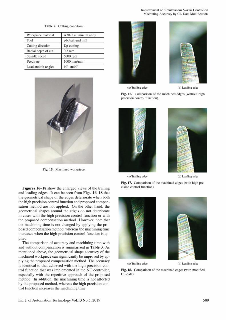
In order to confirm the effectiveness of the proposedmethod in real machining processes, actual machiningtests were carried out under three conditions: 1) with-out either the high precision control function or the pro-posed compensation method, 2) with the high precisioncontrol function only, and 3) with the proposed compen-sation method only. The cutting conditions for the testsare listed in Table 2. In the real machining process, thelead angle is set to 10◦ to avoid machining by the tooltop, which has zero cutting velocity. It is clear that themotion of each axis does not change owing to the lead an-gles although the initial angles and positions are changed.Fig. 15 shows the entire view of the machined workpiece.Both the edges of each workpiece are observed with a dig-ital micro scope.
588 Int. J. of Automation Technology Vol.13 No.5, 2019
Improvement of Simultaneous 5-Axis ControlledMachining Accuracy by CL-Data Modification
Table 2. Cutting condition.
Workpiece material A7075 aluminum alloy
Tool φ6, ball-end mill
Cutting direction Up-cuttingRadial depth of cut 0.2 mm
Spindle speed 6000 rpm
Feed rate 1000 mm/min
Lead and tilt angles 10◦ and 0◦
Fig. 15. Machined workpiece.
Figures 16–18 show the enlarged views of the trailingand leading edges. It can be seen from Figs. 16–18 thatthe geometrical shape of the edges deteriorate when boththe high precision control function and proposed compen-sation method are not applied. On the other hand, thegeometrical shapes around the edges do not deterioratein cases with the high precision control function or withthe proposed compensation method. However, note thatthe machining time is not changed by applying the pro-posed compensation method, whereas the machining timeincreases when the high precision control function is ap-plied.
The comparison of accuracy and machining time withand without compensation is summarized in Table 3. Asmentioned above, the geometrical shape accuracy of themachined workpiece can significantly be improved by ap-plying the proposed compensation method. The accuracyis identical to that achieved with the high precision con-trol function that was implemented in the NC controller,especially with the repetitive approach of the proposedmethod. In addition, the machining time is not affectedby the proposed method, whereas the high precision con-trol function increases the machining time.
(a) Trailing edge (b) Leading edge
Fig. 16. Comparison of the machined edges (without highprecision control function).
(a) Trailing edge (b) Leading edge
Fig. 17. Comparison of the machined edges (with high pre-cision control function).
(a) Trailing edge (b) Leading edge
Fig. 18. Comparison of the machined edges (with modifiedCL-data).
Int. J. of Automation Technology Vol.13 No.5, 2019 589

Sato, R. et al.
Table 3. Comparison of accuracy and machining time.
Accuracy Time
High precision control function: OFFCL-data modification: OFF
× 4.6 s
High precision control function: ONCL-data modification: OFF
© 5.8 s
High precision control function: OFFCL-data modification: ON
© 4.6 s
7. Conclusions
In this study, a CL-data modification method based onTCP trajectory was applied to simultaneous 5-axis con-trolled machining motion. A twisted blade machiningprocess that requires simultaneous 5-axis control motionwas performed to evaluate the CL-data modification. Bycomparing not only machining accuracy but also machin-ing time before and after compensation, the followingconclusions can be drawn.
1) The geometrical shape accuracy of the machinedworkpiece can significantly be improved by applyingthe proposed compensation method.
2) The accuracy is identical to that obtained with the highprecision control function that was implemented in theNC controller.
3) The machining time is not affected by the proposedmethod, whereas the high precision control functionincreases the machining time.
It is expected that the proposed CL-data modificationmethod can be an effective tool for improving both themachining accuracy and productivity of 5-axis machiningprocesses. The authors will also attempt to apply the pro-posed method to other types of machine tools and work-pieces.
AcknowledgementsThe authors would like to sincerely acknowledge all the sup-port from MTTRF. The authors also express special gratitude toMr. Daisuke Sakamoto, who was an undergraduate student atKobe University in 2018, for performing the actual machiningtests.
References:[1] Y. Takeuchi and T. Watanabe, “Generation of 5-axis Control
Collision-free Tool Path and Post Processing for NC Data,” CIRPAnnals – Manufacturing Technology, Vol.41, Issue 1, pp. 539-542,1992.
[2] J. Kaneko, “Visualization and Optimization Method for Multi AxisControlled Machining Process,” J. of the Japan Society for PrecisionEngineering, Vol.78, No.9, pp. 757-762, 2012 (in Japanese).
[3] ISO 230-1, “Test Code for Machine Tools – Part 1: Geometric Ac-curacy of Machines Operating under No-Load or Quasi-Static Con-ditions,” 2012.
[4] S. Ibaraki and W. Knapp, “Indirect Measurement of Volumetric Ac-curacy for Three-axis and Five-axis Machine Tools: A Review,” Int.J. Automation Technol., Vol.6, No.2, pp. 110-124, 2012.
[5] S. Ibaraki, M. Sawada, A. Matsubara, and T. Matsushita, “Machin-ing Tests to Identify Kinematic Errors on Five-axis Machine Tools,”Precision Engineering, Vol.34, No.3, pp. 387-398, 2010.
[6] S. Ibaraki and Y. Ota, “A Machining Test to Calibrate Rotary AxisError Motions of Five-axis Machine Tools and its Application toThermal Deformation Test,” Int. J. of Machine Tools & Manufac-ture, Vol.86, pp. 81-88, 2014.
[7] A. Velenosi, G. Campatelli, and A. Scippa, “Axis Geometrical Er-rors Analysis Through a Performance Test to Evaluate KinematicError in a Five Axis Tilting-rotary Table Machine Tool,” PrecisionEngineering, Vol.39, pp. 224-233, 2015.
[8] M. Tsutsumi, D. Yumiza, K. Utsumi, and R. Sato, “Evaluation ofSynchronous Motion in Five-axis Machining Centers with a TiltingRotary Table,” J. of Advanced Mechanical Design, Systems, andManufacturing, Vol.1, No.1, pp. 24-35, 2007.
[9] R. Sato and M. Tsutsumi, “Dynamic Synchronous Accuracy ofTranslational and Rotary Axes,” Int. J. of Mechatronics and Manu-facturing Systems, Vol.4, Nos.3-4, pp. 201-219, 2011.
[10] R. Sato, Y. Sato, K. Shirase, G. Campatelli, and A. Schippa, “Fin-ished Surface Simulation Method to Predicting the Effects of Ma-chine Tool Motion Errors,” Int. J. Automation Technol., Vol.6, No.8,pp. 801-810, 2014.
[11] M. Tomizuka, “Zero-phase Error Tracking Algorithm for DigitalControl,” Trans. of the ASME, J. of Dynamic Systems, Measure-ment, and Control, Vol.109, pp. 65-68, 1987.
[12] R. Sato and M. Tsutsumi, “High Performance Motion Control ofRotary Table for 5-Axis Machining Centers,” Int. J. AutomationTechnol., Vol.1, No.2, pp. 113-119, 2007.
[13] P. K. Kulkarni and K. Srinivasan, “Optimal Contouring Control ofMulti-Axial Feed Drive Servomechanisms,” Trans. of the ASME, J.of Engineering for Industry, Vol.111, pp. 140-148, 1989.
[14] C.-S. Chen and L.-Y. Chen, “Cross-coupling Position CommandShaping Control in a Multi-axis Motion System,” Mechatronics,Vol.21, pp. 625-632, 2011.
[15] Y. Koren, “Cross-coupled Biaxial Control for Manufacturing Sys-tems,” Trans. of the ASME, J. of Dynamic Systems, Measurement,and Control, Vol.102, pp. 65-68, 1980.
[16] B. Sencer, Y. Altintas, and E. Croft, “Feed Optimization for Five-axis CNC machine Tools with Drive Constraints,” Int. J. of MachineTools & Manufacture, Vol.48, pp. 733-745, 2008.
[17] Y. Sun, Y. Zhao, Y. Bao, and D. Guo, “A Smooth Curve Evolu-tion Approach to the Feedrate Planning on Five-axis Toolpath withGeometric and Kinematic Constraints,” Int. J. of Machine Tools &Manufacture, Vol.97, pp. 86-97, 2015.
[18] FANUC Ltd., “FANUC 30i/31i/32i Operator’s Manual,”B-63944EN, 2011.
[19] Siemens AG, “SINUMERIK Tool and Mold Making Manual,”No.6FC5095-0AB20-0BP0, 2007.
[20] Dr. Johannes Heidenhain GmbH, “iTNC530 Information for theMachine Tool Builder,” 363 808-2C, 2011.
[21] T. Otsuki, H. Sasahara, and R. Sato, “A Method for Evaluating theSpeed and Accuracy of CNC machine Tools,” Proc. of the 9th Int.Conf. on Leading Edge Manufacturing in 21st Century (LEM21),No.034, 2017.
[22] T. Otsuki, H. Sasahara, and R. Sato, “Method for Generating CNCPrograms Based on Block-Processing Time to Imorive Speed andAccuracy of Machining Curved Shapes,” Precision Engineering,Vol.55, pp. 33-41, 2018.
[23] C.-S. Chena, Y.-H. Fanb, and S. P. Tseng, “Position CommandShaping Control in a Retrofitted Milling Machine,” Int. J. of Ma-chine Tools & Manufacture, Vol.46, pp. 293-303, 2006.
[24] T. Miura and Y. Yamaguchi, “Machine Control Method, Pub-lished Unexamined Patent Application,” Japan Patent Office, H08-185211, 1996 (in Japanese).
[25] T. Ueguchi and S. Maekawa, “CNC Data Correction Method,” Pub-lished Unexamined Patent Application, Japan Patent Office, H09-269808, 1997 (in Japanese).
[26] R. Sato, S. Hasegawa, K. Shirase, M. Hasegawa, A. Saito, and T.Iwasaki, “Motion Accuracy Enhancement of 5-axis Machine Toolsby Modified CL-data,” Int. J. Automation Technol., Vol.12, No.5,pp. 699-706, 2018.
590 Int. J. of Automation Technology Vol.13 No.5, 2019

Improvement of Simultaneous 5-Axis ControlledMachining Accuracy by CL-Data Modification
Name:Ryuta Sato
Affiliation:Associate Professor, Department of MechanicalEngineering, Graduate School of Engineering,Kobe University
Address:1-1 Rokko-dai, Nada, Kobe 657-8501, JapanBrief Biographical History:2004- Research Associate, Tokyo University of Agriculture andTechnology2008- Researcher, Mitsubishi Electric Corporation2010- Assistant Professor, Kobe University2013- Associate Professor, Kobe UniversityMain Works:• “Finished Surface Simulation Method to Predicting the Effects ofMachine Tool Motion Errors,” Int. J. Automation Technol., Vol.6, No.8,pp. 801-810, 2015.• “Influence of Motion Error of Feed Drive Systems on MachinedSurface,” J. of Advanced Mechanical Design Systems and Manufacturing,Vol.6, No.6, pp. 762-767, 2012.• “Generation Mechanism of Quadrant Glitches and Its Compensation ofFeed Drive Systems for NC Machine Tools,” Int. J. Automation Technol.,Vol.6, No.2, pp. 154-162, 2012.Membership in Academic Societies:• Japan Society of Mechanical Engineers (JSME)• Japan Society for Precision Engineering (JSPE)• Society of Instrument and Control Engineers (SICE)
Name:Kiichi Morishita
Affiliation:Graduate Student, Graduate School of Engineer-ing, Kobe University
Address:1-1 Rokko-dai, Nada, Kobe 657-8501, JapanBrief Biographical History:2017- Master Course Student, Kobe University2019- Daikin Industries, Ltd.Membership in Academic Societies:• Japan Society of Mechanical Engineers (JSME)
Name:Isamu Nishida
Affiliation:Assistant Professor, Department of MechanicalEngineering, Graduate School of Engineering,Kobe University
Address:1-1 Rokko-dai, Nada, Kobe 657-8501, JapanBrief Biographical History:2012- Sysmex Corp.2016- Assistant Professor, Kobe University2018- CEO, BESTOWS Co., Ltd.Main Works:• “Cutting Force Simulation in Minute Time Resolution for Ball EndMilling Under Various Tool Posture,” J. of Manufacturing Science andEngineering (ASME), Vol.140, No.2, doi: 10.115/1.4038499, 2017.• “Voxel Based End-Milling Simulation Considering Elastic Deflection ofTool System,” J. of the Japan Society for Precision Engineering, Vol.84,No.6, pp. 572-577, 2018.• “Automatic process planning system for end-milling operationconsidering CAM operator’s intention,” Trans. of the JSME, Vol.84,No.860, 17-00563, doi: 10.1299/transjsme.17-00563, 2018 (in Japanese).Membership in Academic Societies:• Japan Society of Mechanical Engineers (JSME)• Japan Society for Precision Engineering (JSPE)
Name:Keiichi Shirase
Affiliation:Professor, Department of Mechanical Engineer-ing, Graduate School of Engineering, Kobe Uni-versity
Address:1-1 Rokko-dai, Nada, Kobe 657-8501, JapanBrief Biographical History:1984- Research Associate, Kanazawa University1995- Associate Professor, Kanazawa University1996- Associate Professor, Osaka University2003- Professor, Kobe UniversityMain Works:• K. Shirase and K. Nakamoto, “Simulation Technologies for theDevelopment of an Autonomous and Intelligent Machine Tool,” Int. J.Automation Technol., Vol.7, No.1, pp. 6-15, 2013.• T. Kobayashi, T. Hirooka, A. Hakotani, R. Sato, and K. Shirase, “ToolMotion Control Referring to Voxel Information of Removal Volume VoxelModel to Achieve Autonomous Milling Operation,” Int. J. AutomationTechnol., Vol.8, No.6, pp. 792-800, 2014.• M. M. Isnaini, Y. Shinoki, R. Sato, and K. Shirase, “Development ofCAD-CAM Interaction System to Generate Flexible Machining ProcessPlan,” Int. J. Automation Technol., Vol.9, No.2, pp. 104-114, 2015.• K. Shirase, “CAM-CNC integration for innovative intelligent machinetool,” Proc. of the 8th Int. Conf. on Leading Edge Manufacturing in 21stCentury (LEM21), A01, 2015.• I. Nishida, R. Okumura, R. Sato, and K. Shirase, “Cutting ForceSimulation in Minute Time Resolution for Ball End Milling Under VariousTool Posture,” ASME J. of Manufacturing Science and Engineering,Vol.140, No.2, 021009, doi: 10.1115/1.4037427, 2018.Membership in Academic Societies:• American Society of Mechanical Engineers (ASME)• Society of Manufacturing Engineers (SME)• Japan Society of Mechanical Engineers (JSME), Fellow• Japan Society for Precision Engineering (JSPE), Fellow
Int. J. of Automation Technology Vol.13 No.5, 2019 591

Sato, R. et al.
Name:Masanobu Hasegawa
Affiliation:Senior Researcher, Metal Processing and Ma-chining Group, Material Processing TechnologyDepartment, Production Engineering Center, IHICorporation
Address:1 Shin-nakahara-cho, Isogo-ku, Yokohama 235-8501, JapanBrief Biographical History:2006- Researcher, IHI CorporationMain Works:• “High Efficiency Machining through the Employment of MachiningSimulation Technology,” IHI Engineering Review 2012, Vol.45, No.2,pp. 35-38, 2012.Membership in Academic Societies:• Japan Society for Precision Engineering (JSPE)
Name:Akira Saito
Affiliation:Material Processing Technology Department,Production Engineering Center, IHI Corporation
Address:1 Shin-nakahara-cho, Isogo-ku, Yokohama 235-8501, JapanBrief Biographical History:2015- IHI CorporationMain Works:• “A Novel Deep Groove Machining Method Utilizing Variable-pitch EndMill with Feed-directional Thin Support,” Precision Engineering, Vol.43,pp. 277-284, 2016.Membership in Academic Societies:• Japan Society of Mechanical Engineers (JSME)
Name:Takayuki Iwasaki
Affiliation:Manager, Material Processing Technology De-partment, Production Engineering Center, IHICorporation
Address:1 Shin-nakahara-cho, Isogo-ku, Yokohama 235-8501, JapanBrief Biographical History:1993- IHI CorporationMain Works:• “High Efficiency Machining through the Employment of MachiningSimulation Technology,” IHI Engineering Review 2012, Vol.45, No.2,pp. 35-38, 2012.Membership in Academic Societies:• Japan Society of Mechanical Engineers (JSME)• Japan Society for Technology of Plasticity (JSTP)
592 Int. J. of Automation Technology Vol.13 No.5, 2019
Powered by TCPDF (www.tcpdf.org)