Embed Size (px)
Citation preview
ISBN 978-80-261-0602-9, © University of West Bohemia, 2016
Improvement of induction motor drive performance using predictive control method
instead of DTC method Pavel Karlovský, Jiří Lettl
Department of Electric Drives and Traction Faculty of Electrical Engineering, Czech Technical University in Prague
Prague, Czech Republic [email protected], [email protected]
Abstract – Considering the disadvantages of induction motor drive such as torque ripple and current waveform distortion when using direct torque control (DTC) method, the method substitution might improve the drive behaviour. The authors suggest instead of the DTC method using the predictive method based on similar principles. In the paper, both methods are examined. Then on the induction motor drive yet controlled by DTC algorithm, the predictive method is implemented and performances of both control strategies are compared.
Keywords – direct torque control, predictive control, induction motor drive
I. USED SYMBOLS Us Stator voltage, [V] Is Stator current, [A] Ψs Stator magnetic flux, [Wb] Ψr Rotor magnetic flux, [Wb] T Torque, [Nm] Rs Stator resistance, [Ω] Rr Rotor resistance, [Ω] Lm Mutual inductance, [H] Lr Rotor inductance, [H] Ls Stator inductance, [H] LΔ LΔ = Ls ・Lr - Lm
2, [H] pp Number of pole pairs, [-] θsr Angle between stator
and rotor flux vectors, [rad] θs Angle of stator flux vector, [rad] θr Angle of rotor flux vector, [rad] k, k+1 Actual sample, next step sample, [-] ωr Electrical angular velocity of rotor [rad/s] Ts Sampling time, [s]
II. INTRODUCTION In recent time, in the field of electric drives, the
most widely used one is a drive with an induction motor because of its simplicity, robustness, and low price. On the other side, such induction motor drive needs sophisticated control algorithms if specific control is required. In many applications, the strategy called direct torque control (DTC) is utilized. This strategy was developed in 1986 when Isao Takahashi and Toshihiko Noguchi presented their new induction motor drive control algorithm [1]. The method is relatively easy to implement. However, one of the
main disadvantages is relatively high ripple in torque waveform that is due to the difficulties in maintaining the desired hysteresis. Some modifications to eliminate this disadvantage have been performed since then. For example, the DTC enhancements using space vector modulation [2], decomposition of the flux space vector into more sectors [3] or the use of multilevel inverter [4]. This paper deals with an attempt to substitute the DTC algorithm in a specific induction motor drive by predictive method consisting in the similar principles as the classical DTC algorithm. The used predictive method is based on prediction of voltage vector that should eliminate the torque ripple while maintaining the same number of switching of the power transistors [5] and [6].
III. METHODS
A. Direct Torque Control Generally, there is a variety of equivalent ways
of expressing the torque generated by the induction motor. The one used to derive this control strategy involves vectors of stator and rotor magnetic fields and it is expressed as (1).
(1)
From the equation, it is clear that the generated torque is dependent on the amplitudes of vectors of both magnetic fields, as well as on the angle between these two vectors. Typically, constant amplitudes of magnetic field vectors are required in an electric machine. Accepting this demand, the only possible way of changing the torque is to change the angle between the magnetic flux vectors. It is easy to change the stator flux vector very quickly by means of the supplying voltage. The rotor flux vector then follows the stator flux vector with certain delay dependent on the induction motor parameters. This feature is employed in this control strategy. The aim of the strategy is to manipulate the supply voltage in such a way that the angle (and therefore a generated torque) is being held in a certain range of values. At the same time, it is possible to maintain the amplitude of stator magnetic flux at its desired value.
In the algorithm, in every step, the actual torque and flux amplitude are calculated and compared

to their references. Then using hysteresis controllers, the information, in which directions should the torque and flux amplitude move, is obtained. The flux vector position is identified and according to the directions and table the most suitable vector is selected. The most commonly used table is shown in table 1 and the block diagram of the method is depicted in figure 1.
Table 1: Switching table Demands Fluxvectorposition
Flux Torque 1 2 3 4 5 6
ψ*=0T*=1 V2 V3 V4 V5 V6 V1T*=0 V7 V0 V7 V0 V7 V0T*=-1 V6 V1 V2 V3 V4 V5
ψ*=1T*=1 V3 V4 V5 V6 V1 V2T*=0 V0 V7 V0 V7 V0 V7T*=-1 V5 V6 V1 V2 V3 V4
Fig. 1 Block diagram of the DTC method
B. Predictive Control The method that should replace the DTC method
is based on the similar principle. It comes out from the same equation for generated torque. But, unlike the DTC method, in every step, it calculates not only torque and stator flux vector but moreover the rotor flux vector. Thanks to this, the algorithm has better knowledge about the angle and it can calculate in advance how would any voltage vector affect the torque waveform and choose the most suitable one. The predictive part consists in the following principles.
The voltage vector on the stator is described by well-known equation of the induction motor (2) and after its discretization it is rewritten for actual step as (3) and for the next step as (4).
(2)
(3)
(4)
The voltage vector us(k+1) is the desired value. In the equation above, all variables are known from either measurement or from mathematical model of the motor that is also used in DTC strategy except the magnetic flux vector of the very next step ψs(k+1).
The flux vector can be defined as its amplitude and phase as (5).
(5)
As the amplitude of the flux vector changes slowly and we want to reach the reference, it is possible to regard the reference value of amplitude as the next step value. The correct determination of the angle is then critical for the accuracy of the method. The relations between flux vectors are depicted in figure 2
Fig. 2 Relations between magnetic fluxes
and the necessary equation is expressed as (6).
(6) As the strategy uses mathematical model
of induction motor, the rotor magnetic flux vector is also being calculated. Therefore, the first part of the equation is known. From the equation (1), the angle between stator and rotor flux can be expressed as (7).
(7)
As the value of the next step of the angle is demanded, all the time dependent variables must be replaced in the next step. Moreover, some simplifications must be accepted. Firstly, reaching the desired state of the torque and stator flux amplitude values is expected to happen in the very next step, so the values can be replaced by their references. And secondly, as the rotor time constant is much greater than the stator time constant, the changes in stator part occurs in rotor part with longer time delay. Therefore, the amplitude of the rotor flux in the next step can be regarded to be the same as the actual amplitude, when the sampling time is adequately short. The following formula (8) expresses all the adjustments and assumptions mentioned above.
(8)
The last part of the equation (6) is the shift of the angle of rotor flux vector during one step. The expression can be achieved from the rotor voltage equation of induction motor as shown in formula (9).
(9)
Now, all the necessary variables are known and the stator voltage vector of the next step can be computed.
The block diagram of the method [6] is depicted in figure 3.
Fig. 3 Block diagram of the predictive method
IV. RESULTS Both strategies were examined in MatLab
Simulink simulation environment first and then the possibility of the method substitution was tested on real drive with induction motor. The drive consisted of rectified power source, power inverter, and three phase induction motor of 5.5 kW. The nominal values of the motor are shown in the table 2.
Table 2: Induction motor nominal values Un 230 V Nominal voltage In 11.8 A Nominal current Pn 5.5 kW Nominal power ω n 145 rad/s Nominal speed
Y Star connected pp 2 Number of pole pairs
All other parameters used in mathematical model of induction motor such as Rs, Rr, Lm or LΔ were measured or calculated under specific conditions and then the drive was kept in these conditions during the whole measurement to prevent changing the parameter values.
As a passive and adjustable load, a separately excited DC motor with its terminals connected to the sliding resistance and its shaft connected to the induction motor was employed. The voltage vector was calculated from DC link voltage level and from switching combination. The stator currents of two phases of the motor were measured using Hall’s sensors and the third one was computed.
The examined control strategies themselves were implemented on dSPACE DS1103 platform and the references were given through connected computer. The switching frequency of the DTC method was limited only by the minimal time loop of the dSPACE platform in such a way that every change in switching of the transistors could be performed only once per 50 µs. The torque and flux hysteresis controllers were set to maintain minimal bandwidth that was reachable with the given switching time. To make the methods more comparable, the PWM block in the predictive method was removed and only the nearest voltage vector was chosen for the whole period. The duration of each voltage vector was set to 50 µs in order to make it corresponding with the DTC method. Also the speed controller was removed and torque reference was set directly. The very similar conditions were achieved in this way.
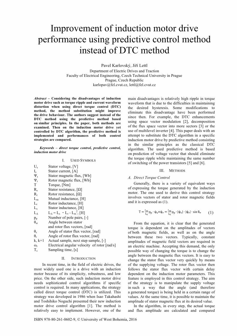
A. Simulation results The tests investigating a response of the generated
torque, flux amplitude, and phase currents to the step change in torque reference were performed in simulation environment and the results are shown in figure 4. It is evident that the obtained results are very similar and both strategies are able to drive generated torque towards its reference value quickly, without overshoots and without any distortions in flux amplitude.
Fig. 4 Response to the step change in torque reference; on the left – DTC, on the right –
predictive control method
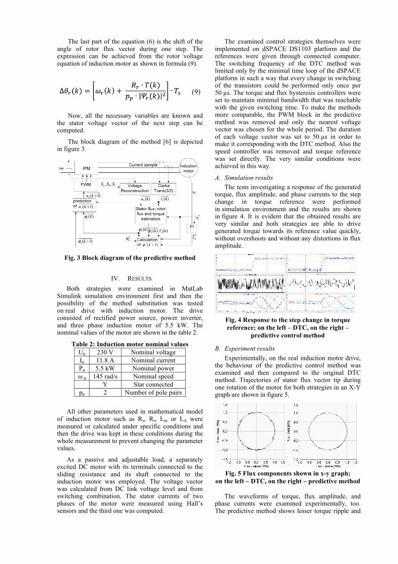
B. Experiment results Experimentally, on the real induction motor drive,
the behaviour of the predictive control method was examined and then compared to the original DTC method. Trajectories of stator flux vector tip during one rotation of the motor for both strategies in an X-Y graph are shown in figure 5.
Fig. 5 Flux components shown in x-y graph; on the left – DTC, on the right – predictive method
The waveforms of torque, flux amplitude, and phase currents were examined experimentally, too. The predictive method shows lesser torque ripple and

lower distortion in currents waveforms as it is presented in figure 6.
Fig. 6 Measured waveforms in steady state run, on the left – DTC, on the right – predictive method
V. CONCLUSION In the paper, authors present possibility of the
substitution of the DTC method by the predictive control method. These two methods are based on the similar functional principles. The classical DTC method changes value of the angle between rotor and stator flux vectors without knowledge of the rotor flux vector. The examined predictive control method differs from the first one in extra rotor flux vector calculation and therefore the angle between rotor and stator flux vectors can be determined more precisely. Both methods were simulated in MatLab Simulink and simulation results were verified experimentally on real induction motor drive. The obtained results of simulation and measurement at both control methods were analysed and compared.
To the presented results, a few remarks must be highlighted. These results were obtained under the condition that all necessary parameters are known and they do not change with time. If some values of parameters differ from the real ones the stability of the method decreases and the waveforms become rougher. These conditions can’t be ensured always in real applications as they were in laboratory. Otherwise, sophisticated methods for online identification of parameters are required to be included in the algorithm. The same problem also occurs and is often discussed in field oriented control as it also requires very accurate model of the motor. Other disadvantages of predictive method are its time consuming calculation of the induction motor model and the necessity of speed sensor.
From the results, a quick and precise response to the step change in torque reference value without overshoots is evident at both strategies. Both strategies can also handle maintaining the stator flux vector tip circular trajectory. Further, a smoother torque and current waveforms in case of predictive method are observable. The ripple in torque waveform is reduced and the current waveforms are less distorted while the switching frequency remains the same. Finally, based on the presented results, in applications where the parameter identification is not an issue and where the speed sensor is already embedded, the proposed substitution of the methods can improve the drive performance substantially.
ACKNOWLEDGMENT This material is based on the work supported by the Technology Agency of the Czech Republic under the grant for Competence Centres Programme project No. TE02000103 and by the Student Grant Agency of Czech Technical University in Prague under grant No. SGS16/152/OHK3/2T/13.
REFERENCES [1] I. Takahashi, T. Noguchi, “A new quick response and high
efficiency control strategy of an induction motor”, IEEE Trans. Ind. Appl., vol. IA-22, pp.820 -827, 1986.
[2] K. B. Lee, F. Blaabjerg, and T. W. Yoon, “Speed-sensorless DTC-SVM for matrix converter drives with simple nonlinearity compensation”, IEEE Trans. Ind. Appl., vol. 43, no. 6, pp. 1639–1649, Nov./Dec. 2007.
[3] B. S. Kumar, R. A. Gupta, R. Kumar, “12-Sector Methodology of Torque Ripple Reduction in a Direct Torque Controlled Induction Motor Drive”, IEEE, SICE-ICASE, 2006. International Joint Conference, p. 3587 - 3592, Oct. 2006.
[4] S. Kouro, R. Bernal, H. Miranda, C. A. Silva, and J. Rodriguez, “High performance torque and flux control for multilevel inverter fed induction motors,” IEEE Trans. Power Electron., vol. 22, no. 6, pp. 2116–2123, Nov. 2007.
[5] Jef Beerten, Jan Verveckken, and Johan Driesen, “Predictive Direct Torque Control for Flux and Torque Ripple,” IEEE Trans. Ind. Appl., vol. 57, no. 1, pp. 404–412, Jan. 2010.
[6] Shengwen Fan, Jianxin Luo, Hu Zhang, A voltage vector prediction direct torque control system for induction motor, “International Conference on Electrical and Control Engineering (ICECE)”, 2011.
[7] P. Vas, Sensorless vector and direct torque control, Oxford University Press, Oxford,1998.
[8] J. Rodriguez, P. Cortes, Predictive Control of Power Converteres and Electrical Drives, 246 pages, Wiley-IEEE Press, Apr. 2012.