Embed Size (px)
Citation preview

i
Master Thesis Software Engineering Thesis no: MSE-2002-27 August 2002
Department of Software Engineering and Computer Science Blekinge Institute of Technology Box 520 SE – 372 25 Ronneby Sweden
- Identification and development of a scripted automation tool that will support hardware basic testing
Pontus Mannestig Ulf Rask
Improvement of hardware basic testing

ii
This thesis is submitted to the Department of Software Engineering and Computer Science atBlekinge Institute of Technology in partial fulfillment of the requirements for the degree ofMaster of Science in Software Engineering. The thesis is equivalent to 20 weeks of full timestudies.
Contact Information: Authors: Pontus Mannestig E-mail: [email protected] Ulf Rask E-mail: [email protected]
External advisor: Paul Wahlsten Ericsson AB E-mail: [email protected] Phone: +46 8 7270000
University advisor: Lars Lundberg Department of Software Engineering and Computer Science
Department of Software Engineering and Computer Science Blekinge Institute of Technology Box 520 SE – 372 25 Ronneby Sweden
Internet : www.bth.se/ipd Phone : +46 457 38 50 00 Fax : + 46 457 271 25
i
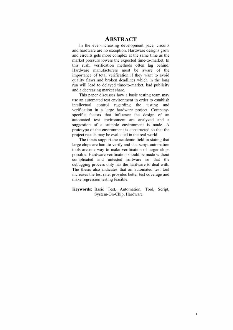
ABSTRACT In the ever-increasing development pace, circuits
and hardware are no exception. Hardware designs grow and circuits gets more complex at the same time as the market pressure lowers the expected time-to-market. In this rush, verification methods often lag behind. Hardware manufacturers must be aware of the importance of total verification if they want to avoid quality flaws and broken deadlines which in the long run will lead to delayed time-to-market, bad publicity and a decreasing market share.
This paper discusses how a basic testing team may use an automated test environment in order to establish intellectual control regarding the testing and verification in a large hardware project. Company-specific factors that influence the design of an automated test environment are analyzed and a suggestion of a suitable environment is made. A prototype of the environment is constructed so that the project results may be evaluated in the real world.
The thesis support the academic field in stating that large chips are hard to verify and that script-automation tools are one way to make verification of larger chips possible. Hardware verification should be made without complicated and untested software so that the debugging process only has the hardware to deal with. The thesis also indicates that an automated test tool increases the test rate, provides better test coverage and make regression testing feasible. Keywords: Basic Test, Automation, Tool, Script,
System-On-Chip, Hardware

ii
CONTENTS
PREFACE................................................................................................................ IV
1 INTRODUCTION................................................................................................ 1
1.1 Target Audience ......................................................................................................... 1
1.2 Reading Guidelines .................................................................................................... 1
1.3 Background ................................................................................................................ 1
1.4 Problem Definition..................................................................................................... 1 1.4.1 Identified areas of improvement .......................................................................... 2 1.4.2 Goal and Expected Effect..................................................................................... 2 1.4.3 Solution Hypotheses ............................................................................................ 2
1.5 Limitation / Scope ...................................................................................................... 2
2 METHODS.......................................................................................................... 3
2.1 Observations (Direct Case Study)............................................................................. 4 2.1.1 Purpose of Observations ...................................................................................... 4 2.1.2 Risks and Compensation ...................................................................................... 4
2.2 Interviews (Direct Case Study) ................................................................................. 4 2.2.1 Purpose of interviews........................................................................................... 4 2.2.2 Risks and Compensation ...................................................................................... 4 2.2.3 Selection of interviewees ..................................................................................... 5
2.3 Literature Study......................................................................................................... 5 2.3.1 Purpose of Literature Study ................................................................................. 5 2.3.2 Risks and Compensation ...................................................................................... 5 2.3.3 Literature Search .................................................................................................. 6 2.3.4 Literature Outcome .............................................................................................. 6
3 RESEARCH OUTCOME.................................................................................... 7
3.1 Results from Observation.......................................................................................... 7 3.1.1 Hardware Basic Testing in Ariadne ..................................................................... 7 3.1.2 Hardware Basic Testing in Cello ......................................................................... 7 3.1.3 Software Basic Testing in Cello........................................................................... 8
3.2 Results from Interviews............................................................................................. 8 3.2.1 Ariadne Project .................................................................................................... 8 3.2.2 Cello Project......................................................................................................... 8 3.2.3 Differences between the Ariadne and Cello projects ........................................... 9
3.3 Literature Study......................................................................................................... 9
4 IMPORTANT ASPECTS .................................................................................. 10

iii
4.1 Usability Aspects ...................................................................................................... 10 4.1.1 Ease of use vs. Formal Verification ................................................................... 10 4.1.2 File Handling Routines ...................................................................................... 10
4.2 Technical Aspects ..................................................................................................... 10 4.2.1 Communication Tradeoffs ................................................................................. 10 4.2.2 On Card Script Interpretation............................................................................. 11 4.2.3 Client Mobility................................................................................................... 11 4.2.4 Interfaces............................................................................................................ 11 4.2.5 Development Languages and Environments...................................................... 11
4.3 A vision of a suitable basic test environment......................................................... 11
5 SOLUTION....................................................................................................... 12
5.1 Situation before prototyping ................................................................................... 12 5.1.1 Hardware............................................................................................................ 12 5.1.2 Identified Bottlenecks ........................................................................................ 12 5.1.3 Additional Hardware Required .......................................................................... 12
5.2 Prototype................................................................................................................... 12 5.2.1 Overview............................................................................................................ 13 5.2.2 Clients ................................................................................................................ 13 5.2.3 Server ................................................................................................................. 13 5.2.4 Card Bay ............................................................................................................ 14 5.2.5 Programming Languages ................................................................................... 14 5.2.6 Protocol / Communication ................................................................................. 14
6 CONCLUSIONS............................................................................................... 15
7 REFERENCES................................................................................................. 16

iv
PREFACE The Authors… …are Pontus and Ulf, two young and even younger by heart technology students
who has yet to become adults and earn their living as most other people do. Since they were not bright enough to become rocket scientists or quite evil enough to take over the world they decided to become masters instead. It’s good to be master of something and Arts was not an option since the French are weird and often quite rude, especially when their weirdness is mentioned. That leaves Computer Science, which is as good as anything else that doesn’t require brains, full color vision or weird language skills. Besides, who don’t like computers…?
Acknowledgements First of all we would like to thank our advisors Paul Wahlsten at Ericsson and Lars
Lundberg at BTH for their patience, support and advice as well as the Ariadne and Cello verification teams for all the information and help that they have patiently given us. We would also like to thank our friends Sofia, Erik, Lisa and Jon-Erik for their help in proofreading our report and making it qualitative in a way that we couldn’t have done alone.
A good quote for the theoretically inclined "In theory, there is no difference between theory and practice. But, in
practice, there is." ~ Jan L.A. van de Snepscheut ~

1
1 INTRODUCTION This chapter serves as an introduction to why this thesis exists, who the intended
readers are and how the following chapters correlate to each other. This chapter also defines the problem that is to be solved as well as the limitations and scope of the thesis.
1.1 Target Audience The intended readers for this thesis are those who are somewhat familiar with the
basics of software or hardware development in projects large enough to require extensive testing. It’s preferable, but not required, that the reader has basic knowledge about verification problems.
1.2 Reading Guidelines This report may be viewed as four different parts with different purposes. The first
part, Essence of the Thesis, holds the purpose of the thesis the major findings. The second part, Topic Introduction, defines the problem and set a foundation on which the rest of the thesis is built. Part three, Investigation, concerns the Methods used to solve the problem and present the Research Outcome that was acquired from specified methods. The final part, Development, is about the Important Aspects that helps to form a solution and how a Solution that will solve the problem looks like.
1.3 Background Ericsson has been a well-known Swedish developer of telecommunication
equipment for more than 125 years. A cornerstone in their business is the development of telephony exchange stations. Two projects that are associated with such development are Ariadne and Cello. It is crucial that these products reach the market with as few defects as possible and as fast as possible. The verification environment is therefore important as it helps finding and removing as many defects as possible. Basic Test is the phase where hardware prototypes are verified and it is here most of the defects are supposed to be found.
This Thesis is mainly concerned with Cello as its verification environment has room for improvement, Ariadne will be used as a reference and comparison project as it has performed well during basic testing.
1.4 Problem Definition The verification process needs to be stable and thought trough in order to find a
majority of the defects. If the verification process does not find a satisfying number of
Figure 1.1: Brief overview of this paper, its contents and general chapteroutline.
Chapter 1Introduction
Chapter 3ResearchOutcome
Chapter 4ImportantAspects
Chapter 5Solution
Chapter 6Conclusions
Chapter 2Methods
Abstract
Essence ofthe Thesis
TopicIntroduction
Investigation Development

2
defects or if the defects are found late in the process the result will be high development costs and increased time-to-market. Ericsson has the ambition to increase the efficiency inside the Cello project and identify areas of improvements.
1.4.1 Identified areas of improvement Tool
● The IBM RISCWatch is the only tool used for verification today. It provides great detail knowledge but unsatisfying test coverage.
● The present situation is that hardware is being verified with help of unverified software. It is difficult and time consuming to determine the origin of the error as the error domain includes both hardware and software.
● Non-automated manual testing makes regression testing inefficient. Team Philosophy
● Basic testing is limited to boundary scans and traffic loop back since manual test methods are time consuming. Automatic testing would increase the test rate and make verification of external circuits feasible.
1.4.2 Goal and Expected Effect The goal for this thesis is to improve the basic test phase in the Cello verification
process by providing an automatic tool that give the test team the ability to cover the vast majority of the functionality and solving the problems stated above. Ericsson expect that the test team shall find more than 90% of all the defects in Basic Test, resulting in kept deadlines, lower costs and a more reliable end product.
1.4.3 Solution Hypotheses The automated test tool should consist of two parts. The first part is a program on
a computer that runs scripts that communicate with the second part, a small on-target OS-independent software module. The purpose of the tool is to provide the verification team with the ability to write scripts on the computer and execute simple read/write instructions on the hardware that is verified. Such a tool should enable the test team to:
● Write automated test routines that help verify a vast majority of the functionality fast.
● Start testing as soon as the hardware becomes available since no operating system is required.
● Include regression testing in the verification program. ● Have the automated tool save and document specific test cases. ● Attain complete test coverage as the speed and simplicity of an automated
tool make it possible to verify circuits from external parties as well.
1.5 Limitation / Scope This thesis is centered on the investigation of the needs of a tool for efficient
hardware verification as well as the development of a prototype of such a tool. The tool shall only be operational in the Cello hardware environment and the prototype shall only work on the GPB device card. The thesis will not concern structural modifications of the verification process, neither development of a fully functioning application.

3
2 METHODS The objective of this chapter is to explain and describe the methods used,
associated risks and the expected outcome of the methods. The methods used in this project may be described as shown in Figure 2.1. The
project began with Case Studies and a Literature Study. Observations (see section 2.1) were made so that general knowledge was assimilated. These were followed by Interviews where specific knowledge was sought. The Literature Study was conducted so that the results from the Observations and Interviews could be validated and compared to independent sources of information. A Recommendation of a suitable end product was made with the help of the three mentioned sources of information and a Prototype was developed so that Ericsson could evaluate the project.
A fourth source of information was sought; the goal was to see how others have built similar systems and what areas they have identified as important. Unfortunately no such sources were found during our search in various databases and on the Internet.
Figure 2.1: Three methods (Observation, Interview, Literature Search) were used to gain enough knowledge to be able to recommend a suitable product. A prototype of the suggested solution was designed and implemented.
StartChapter 1
Get generalknowledgeChapter 3.1
Learn specificknowledgeChapter 3.2
Interviews
Chapter2.2
Observations
Chapter2.1
Recommendationof a suitableend productChapter 4, 5
Find out aboutthe problemChapter 3.3
Search theacademic knowledge
domainChapter 2.3
PROTOTYPE(Ericsson
evaluation ofproject)
Chapter 5, 6, 9
CaseStudies
LiteratureStudy
Designand
implementation
ofprototype
Chapter5
Validate andCompare withAcademic field
Chapter 3.3

4
2.1 Observations (Direct Case Study) This section will present why the observations are considered to be an important
part of the knowledge collection phase. The observation reflects the author’s version of the procedures etc that was observed.
Observations are made by watching the work crews and departments behavior and are good for making a sound base to develop ideas and theories about new systems.
Ericsson has a number of ongoing projects developing telecommunicating hardware and software. The observation started with a personal introduction to the Basic Testing conducted at Ericsson (Indus section) in general, its purpose and goals as well as the methodology used. The introduction also included technical descriptions of the methods and tools used as well as the systems being verified.
2.1.1 Purpose of Observations A purpose of the observations was to a gain general knowledge and sense about
how the Basic Testing was conducted at the Indus section. Another purpose of the observations was to gain specific knowledge about the verification process used so that appropriate questions could be asked. This is important as future findings should be put into context and contribute to an appropriate solution.
2.1.2 Risks and Compensation One of the major advantages in using external parties, like student projects of this
kind, is that they are unbiased and hopefully objective. If the outside parties spend too much time with the normal employees they might be influenced with their ways of working and thinking with the loss of objectiveness as a consequence. This is especially apparent when observing a particular problem and an existing solution that may not be optimal. The observer may become indoctrinated with old ways and trying to fix the present solution instead of finding a new solution that might work better. Care must be taken when choosing the target group so that correct results are acquired.
However observation is necessary because there are often unobvious reasons for why systems and processes are constructed the way they are. By using observation early in a project one may identify and deal with issues that would otherwise affect the project negatively later on.
2.2 Interviews (Direct Case Study) This section will present why the interviews are considered to be an important part
of the knowledge collection phase, what risks that are associated with the interviewing and finally how the interviewees where selected.
The interviews were conducted in accordance with the interviewing techniques proposed by the University of Calgary [UoC] since they seemed to have mature and well-founded interviewing-techniques. The steps proposed are:
● Planning and Scheduling Interviews ● Preparing for the Interview ● Opening the Interview ● Conducting the Interview ● Closing the Interview ● Following Up for Clarification
2.2.1 Purpose of interviews The interviews had two main purposes. One was to gain knowledge about a prior
successful project (Ariadne), its advantages and disadvantages. The other was to learn more about how the project Cello may be improved. The interviews also aimed at resolving visions and features that would be useful when constructing a new system.
2.2.2 Risks and Compensation There are several risks associated with interviews [KotSom]

5
● Application domain terminology ● Interviewer not open minded enough ● Bad conducted interview – no clear starting point ● Stakeholders take knowledge for granted
Kontonya and Sommerville [KotSom] state that stakeholders find it hard to discuss the subject without the accurate terminology. Therefore it is important that the interviewers put much effort in learning the terminology. This was done by observing and following persons in their work, asking questions and verifying that their answer was rightfully interpreted.
After the interviews were conducted and documented, the interviewees were asked to control the content in the interview record, adding, subtracting or changing things so that the interview record reflect the interviewees opinions. All information in all interviews has been taken under consideration and therefore reducing the risk that the interviewers would not be open-minded enough.
The interviews were preceded by handing out interview questions at the same time the interview was scheduled, normally several days in advance. The interviewee was informed that the interview questions were a guideline and was encouraged to address any issue he or she wanted during the interview. The only compensation made in order to avoid the risk that the stakeholder took knowledge for granted was questioning everything that was not understood during the interviews for further explanation.
The information elicited from the interviews was validated to the greatest possible extent with literature study. See section 3.3 for further information.
2.2.3 Selection of interviewees The interviewees were selected by different criteria. These were:
● Project belonging ● Position ● Experience
Project belonging is important since there are different projects/systems involved. Both persons from Cello and Ariadne have been interviewed to fulfill the purposes mentioned above.
Position in the organization is important to get different aspects on the developed tool. Different stakeholders have different visions about how a tool would help them in their work.
Persons with a lot of experience give a reliable impression and can provide a trustworthy over-all picture of the development history. Younger persons, on the other hand, tend to be more ambitious and have fresh and not seldom revolutionary ideas.
2.3 Literature Study This section will present the purpose of the literature study, risk associated with
the literature study, how it was performed and finally how the outcome was processed.
2.3.1 Purpose of Literature Study The purpose of the literature study is to expand the range of knowledge and
enlarge the thesis knowledge domain. To collect experiences from others work is important in order to avoid making the same mistake twice as well as avoiding the reinvention of the wheel.
2.3.2 Risks and Compensation There are many risks associated with literature studies. Christian Dawson
discussed several of them in The Essence of Computing Projects, a student’s guide [ChDaw]. The objectiveness of the articles author(s) is considered as a risk. It is not uncommon that companies and organizations fund articles that affect their cause positively. The articles have been chosen with awareness of this issue. If there have

6
been an external benefactor involved, only information that are considered to be unaffected by the benefactors interests have been taken under consideration.
2.3.3 Literature Search The search aimed at finding prior work related to hardware verification with
automated tools. The literature search was performed at two places, in the library of the Royal Institute of Technology in Stockholm and via the bibliographic search databases provided by the library of Blekinge Institute of Technology, Ronneby.
2.3.4 Literature Outcome The review was made by sorting the articles according to their topic followed by
reading the abstracts of each article, prioritizing it after the MoSCoW [DSDM] criteria:
● Must use ● Should use ● Could use ● Would not use
Judging by the number of articles in the “Must use” and “Should use” domains we took the decision to only include those. Those articles were completely read and the result of this can be found in section 3.3 Literature Study.

7
3 RESEARCH OUTCOME The objective of this chapter is to present the outcome of the methods described in
chapter 2.
3.1 Results from Observation The results from the observation phase are divided into three sections. The first
section concerns the Ariadne project, a project that has had a successful basic test phase. The second section concerns the hardware basic testing area to be improved in the Cello project. The third and last section concerns software basic testing in the Cello project since it has an automated test tool and because cooperation with the software department may be beneficial, during both development and actual testing.
3.1.1 Hardware Basic Testing in Ariadne Ericsson has developed hardware for several years and their knowledge and
experience in this area has contributed to a sophisticated (simple, yet powerful), self-developed verification process. This process consists of inspection, simulation and verification as follows:
● Inspection of Requirements Specification and Design Specification ● Simulation of design ● Inspection of Verification Specification ● Verification of prototype ● Inspection of Verification Record
This methodology has been used in the Ariadne project and has been proven very successful. The defects found after leaving Basic Test hardware (where the process is applied) are as good as negligible compared to those found in software, according to project feedback and report statistics. These statistics and investigations are company-restricted material and therefore not allowed to be presented in this report.
When observing the verifiers in action, it was clear that most of the verifier’s work was carried out with the help of a script engine. By writing automated scripts, the verifier could test certain functionality in the hardware. The verifier wrote JavaScripts that were interpreted by the verifier’s computer and sent as instructions to the hardware being tested. All communication is handled over Ethernet. This method is, according to the verifiers, very time efficient and catch more defects than all prior methods that they have experienced. The hardware requires no software except the module for communicating with the computer issuing the instructions and handling the instructions issued. It is positive that no extra software is required since the operating system normally is not operational at this stage in the development process.
3.1.2 Hardware Basic Testing in Cello Verification of an observed hardware device card is performed by generating
traffic with a certain traffic generator and then analyzing the state (values in registers etc.) of the hardware with a specific hardware component called RISCWatch, developed by IBM. The RISCWatch is connected to a computer, which interprets the result and checks for errors. RISCWatch is also used to upload software drivers (when they are available) that initiate the complex circuits. During the observation some of the verifiers described this way as slow, tedious and expensive while others were of the opinion that the RISCWatch was necessary and that an additional system would not improve the verification process.
Boundary scans are used to see that all physical connections on the cards are OK by looping traffic through them. It is hard to verify circuits from external parties due to deadlines and non-automatic tools. Faster tests with automatic tools may therefore be beneficial as they enable the verification team to include external circuits in the tests.

8
3.1.3 Software Basic Testing in Cello This section concerns the test of the operating system’s functionality. When verifying software, the Cello software verification team uses a Sun
computer and a terminal server (a converter from one Ethernet cable to 16 V.24 cables). The computer communicates with the hardware through the terminal server, which translates the Ethernet traffic to V.24 traffic. Scripts written in Expect [DoLib] are executed on the computer and communicate with software (load modules) on the hardware that will be verified. The scripts hold commands that are specific to each load module. These may be commands that run a LED (light-emitting diode) testing-routine or simulates overheating in a card. An advantage with this method is that the verification may take place at anytime, e.g. over the night if the script is extensive.
The similarities in this environment compared with Ariadne were striking. The theory was the same; use automation via a script engine to perform large tests fast and in a repeatable manner.
3.2 Results from Interviews This section will present the result from the interviews with twelve persons at
Ericsson. The interviews concern Ariadne, Cello, differences between the environments and finally the desired functionality of a new system.
3.2.1 Ariadne Project Ariadne is considered to be a successful project for several reasons. For instance,
its verification process (described in 3.1.1) effectively helps the verification team in finding a lot of errors early. This is likely because it contains a lot of inspections and because it has an automated verification tool that makes verification simpler, faster and more precise than it would be without one. All the interviewees with experience from prior projects advocate this way of working since testing and regression testing is faster, more accurate and the outcome is better as defects can be caught earlier which means shorter development time, lower development costs and shorter time to market.
The interviewees also emphasized the importance of full verification. Even though the circuits work the way that the producer claims, there is no guarantee that the circuits work according to specification when cooperating with other components on the hardware designed by Ericsson.
The interviewees showed a natural difficulty to be objective and visionary which was one of the risks identified with interviews. One example is that persons concerned with Ariadne found their environment to be a good ground for verification and most of them had suggestions to improvements, new features etc. regarding the present environment. The reason for this is probably that the verification environment serves its purpose and that only minor improvements are possible.
3.2.2 Cello Project Cello verification strategy is less sophisticated than Ariadne's. For instance, it does
not test functionality in the circuits to their full extent (see section 3.1.2). The interviewees differed in their opinion about the verification strategy. Some interviewees regard circuits bought from external parties as flawless and do not think it is Ericsson’s responsibility to verify those circuits. Others believe that all defects needs to be caught as early as possible in order to achieve a competitive product. This opinion is shared by Barbara Tuck and discussed in her article Integrating IP blocks to create a system-on-chip [BaTuc97].
The case has so far been not to verify external circuits and verification has been performed with RISCWatch, which is difficult to handle. As a result many defects have been detected when integrating hardware with software. The defects found are often hard to trace as there are many unverified components in action both concerning software and hardware at the same time. Barbara Tuck confirms this problem in her article The hardware/software coverification challenge [BaTuc98].

9
A person who has experience from Ariadne and is familiar with Cello and its problematic areas is the on-site supervisor Paul Wahlsten. His knowledge and experience in combination with the good outcome from Ariadne’s verification environment makes him a valuable source with insight from both the Ariadne and Cello projects.
Paul advocates a tool with which it is easy to perform tests and that deliver results that are easy to interpret. It also means that there should be very limited administrative work around the tool and that the verification responsibility lies on the verifier. The objective is to have an easy to use and time effective system that is fun to work with.
People concerned with Cello did not see the needs for a tool helping them with verification. This together with the fact that they have not been in contact with any tool of this kind made it hard for them to imagine other ways of verification.
3.2.3 Differences between the Ariadne and Cello projects There are different verification methods in the projects (see 3.2.1 and 3.2.2).
Looking at defect-statistics regarding the projects one can draw conclusions in line with Barbara Tuck [BaTuc98] that the Ariadne way, to discover defects as early as possible, is preferable. Ariadne seems to have a more mature process with full verification and a great deal of inspections. Ariadne’s process acknowledges the fact that both external and internal hardware may be erroneous and need to be tested to the fullest extent possible.
3.3 Literature Study The literature study aimed at finding solutions to the problem of verifying
hardware described in the Problem Definition (see section 1.4). The literature in the field confirmed the identified problems with hardware verification in large system and supported the need for automated verification. However there were no articles that showed how an automated tool would look like or what aspects that was important when designing such a tool. Barbara Tuck confirms in two articles that [BaTuc97], [BaTuc98]
● The complete design needs to be verified ● There are usually defects in other vendors hardware ● Verification methodology should be as automated as possible ● There is a great uncertainty if the defect belongs to the hardware, software
or prototype manufacturing. ● It is an advantage to find defects early in the verification cycle
Charles Babcock say in his article “Web developers Follow Old Scripts” [ChBab] that interpreted languages are time efficient for development by stating that “Interpreted languages are good for development, however, developers can create code and test-drive it quickly, trying out their changes almost as fast as they can make them”.
The hardware in Cello uses several Ericsson-designed ASICs (application-specific integrated circuit) and FPGAs (field-programmable gate array). These circuits require extensive verifications according to Gregor Siwinski [GrSiw]. The fact that circuits gets more complicated has also been observed by Duchscher and Hussain [DunHus]. They state that this in combination with the decreasing time to market has created a need for new verification products and environments. They have identified that manual testing requires a lot of work, especially when the verification needs to be repeated. They advocate the usage of scripts for automation and state that test performed with scripts increases the test coverage.
Prototype verification often reveals defects that should be discovered in simulation, something that has been observed by Dino Caporossi [DiCap] who states that simulation is slow and has a bad coverage. He also considers the verification to be harder than the actual development.

10
4 IMPORTANT ASPECTS This chapter describes the important factors and tradeoffs that the authors has
identified as relevant when building a hardware basic testing system such as the one needed by the Cello hardware verification team. Factors such as Communication Standards, File Handling Routines etc are divided into two categories; Usability Aspects that affect the user in a very direct way, and Technical Aspects that affect the programmers and system administrators more than the users.
4.1 Usability Aspects Usability Aspects affect the user in a very direct way. These may be part of a
software system or just work routines that are required for the work to run smoothly.
4.1.1 Ease of use vs. Formal Verification Important factors when building a test/verification system are traceability and
usability factors. A verification system with low traceability and high usability in which it is very easy to write and run tests is not of much use in a formal verification environment where one want to know exactly what was done and what the result looked like. On the other hand - a system with rigorous traceability but low usability where much time is lost to administration is not very time-effective for the testers when writing tests. Everything could be logged so that time was not lost to administration, but then much useless information would be stored resulting in a waste of storage space. Even more important, logged errors would be drowned by and lost in a myriad of useless information.
4.1.2 File Handling Routines Another usability aspect is the file handling routines. Files tend to get large and
complex as the number of employees and project grows. File control may be introduced in order to minimize the negative effects that arise when many people work with the same files. There are many levels of file control, ranging from having all the files available on a server in a public storage folder to having a file handling system like Clear Case or CVS controlling the files. In the article about Achieving ROI (return-on-investment) with Rational Clear Case [HenHei] the authors state that Clear Case has helped the companies involved in their study. However the article should be read with some caution as Rational (the makers of Clear Case) has funded the article.
Overhead is an important factor here as well. Ease of use and simplicity is sacrificed in order to gain control and traceability. Whether one wants an easy to use system and discipline as control measure, or a system with more control is dependent on project size and number of people involved.
4.2 Technical Aspects Technical aspects affect the makers and administrators of a system more than they
affect the user. Factors such as maintainability, speed, cost, security and administration time is affected by the technical aspects.
4.2.1 Communication Tradeoffs There are two ways of communicating with the Cello GPB card, one is via an
Ethernet interface and the other is via a V.24 interface. The Ethernet interface is much faster and permits easy access to multiple cards via networking hardware such as hubs, routers etc. V.24 on the other hand requires hardly any software support but accessing multiple cards is neither easy nor cheap as special hardware is required. An important issue is that other test departments use V.24 as the testing interface later in the development process. Easy cooperation with basic test systems may be beneficial in later stages of production.

11
4.2.2 On Card Script Interpretation Extreme speed increase may be experienced if the scripts were transferred to and
interpreted by software on the target, similar to java virtual machine technology. This is because a script running on a computer/server and commanding the target via simple instructions will use the communications medium as a data bus, which is remarkably slow compared with the internal bus. On-target interpretation increases time resolution and results in more accurate testing and debugging capabilities. A drawback is that an interpreter that possibly holds unwanted bugs must be put on target. Another drawback is the loss of runtime control as the script runs independently and returns with feedback upon completion.
4.2.3 Client Mobility The ability to work from different locations is valued today and increases with the
expansion of the Internet, as it is the largest network available. Performance is often sacrificed in order to gain mobility. Mobility range from immobile hardware dependent programs to more mobile Java applications/applets and web interfaces which run on virtually any modern browser. It is important to set the mobility level early in the project as it affects the software design.
4.2.4 Interfaces It is not possible to foresee how a system will interact with other systems in the
future. It is therefore important to keep the communication interfaces open and documented so that it is easy to expand the system with possible benefits such as increased traceability and reduced time to market.
4.2.5 Development Languages and Environments Language and environment choices affect performance and maintenance of the
developed system. High performance languages such as C or C++ are not very portable between different operating systems and interpreted languages such as Java or Erlang are slower but more portable. Java is being developed and changes over time and programs get obsolete or deprecated (Java API). The choice of work environment and operating system also affect the solution but is more dependent on what the testing team uses today.
4.3 A vision of a suitable basic test environment We have a vision of how the verification tool should be constructed and how it
could improve the verification process. The verification tool should offer the verifier the possibility to choose whether he wants to perform a simple unlogged test or if he feels confident and wants to make a logged test run. The logged test run takes more time but has options for storing much more detail that increase traceability and forms a base for verification decisions later on.
A version handling system for files is needed to reduce the risk of careless mistakes by the verifiers. Such a system may reduce the usability of the system but advantages such as intellectual control are prioritized. The formal verification record should not be seen as a verification record, but can be used for strong traceability and control over performed tests. When it comes to communication, Ethernet seems to be a great alternative with its superior speed, the ability to buy COTS to a reasonable price and the advantage of worldwide mobility through Internet. The fairly strong security around file access can be apprehended as circumstantial to work with and decrease the usability slightly.
It would be an advantage to have the ability to interpret code on the card and thereby achieve even faster verification. A disadvantage with on-target interpretation is that it requires a larger software module on the target. The risk of software bugs increase as the module size grows and lead to less reliable verification.

12
5 SOLUTION This chapter will show how the important factors and tradeoffs discussed in
chapter 4 have been assessed in order to build a system suitable for the Cello hardware testing team. There are two main sections; the first one briefly describes the situation before the system has been built and show that new hardware is required. The second section shows how the system should be built and motivate why.
5.1 Situation before prototyping A view of the current situation at Ericsson must be established and analyzed
before a proper system may be built.
5.1.1 Hardware The Cello project use mainly UNIX workstations during both development and
basic testing. The target cards use V.24 interfaces. The main tool for verification is the RISCWatch (see section 3.1.2).
5.1.2 Identified Bottlenecks There are both physical and performance bottlenecks in the current hardware. The
physical bottleneck is that a standard UNIX workstation or PC has one or two V.24 interfaces (Serial Communication Ports) and that there are many cards to verify. The performance bottleneck is that the standard V.24 interface is capable of a maximum of 115200 baud.
This means that one computer is needed to verify two device-cards at the same time. It also means that the computers processor will be almost unused because of the very low transfer rate of the V.24 interfaces.
The conclusion to draw from this is that many computers are needed if verification of many cards shall take place at once. Most of the computers processor power can not be used. Or in other words - low and therefore expensive performance should be expected without additional hardware.
5.1.3 Additional Hardware Required Extra hardware is required if one computer is to be able to verify more than one or
two cards at the same time. There are several ways to expand the V.24 capabilities of a computer; in this case a V.24 terminal server is suitable. A V.24 terminal server connects many V.24 interfaces to one Ethernet interface. Data are written and read sequentially by writing and reading data via the terminal server’s IP number and a port number representing a com-port on the terminal server.
Terminal servers enable one computer to verify any number of cards via a TCP/IP connection. The bottleneck concerning the V.24 interface transfer rate still remains and cannot be remedied.
5.2 Prototype The prototype defined in this section is designed to suit the Cello hardware
verification team. The developed system focuses on usability instead of information and traceability since the interviewees valued simplicity and speed higher before traceability. All file handling will be taken care of by the standard file handling system, which currently is Clear Case (Rational) in the Cello project environment. Verification records will not be automatically generated, although a log for each processed command will be available. The applications and protocols are developed by the authors.

13
5.2.1 Overview The system developed consists of four parts. These are, as seen in figure 5.1,
Clients, Server, Additional Hardware and Card Bay. Clients are used for user interaction but also automation when needed. Available Clients are as seen in the figure; Script Automation Module, Server Interface and Server and Target Monitor. The Clients sends instructions to the Card Bay (or more specifically the targets located in the card bay) through the Server. The server passes the instructions on to the hardware via the Terminal Server. The Terminal Server acts like an adaptor between Ethernet and V.24. The Target receives the instructions, performs the tasks and sends back answers to the Clients.
5.2.2 Clients The clients are software used for verification and consist of a Script Automation Module,
a Server Interface and a Server and Target Monitor. The automated script environment (see section 3.1.3) used by the Cello Software
verification team is perfect as Script Automation Module for several reasons. The major ones are that the system already exists and is in use and that the TCL syntax used by Expect is similar to C, a language that many in the hardware verification team are familiar with. There is expertise available about Expect within the Cello project and verification at system level is easier if both hardware and software verification is conducted in the same system.
The Server Interface is text based and is used to communicate with the Server Application via TCP/IP. The TCP/IP connections major advantage is mobility. Mobility in the sense that the client and server may be located anywhere as long as they are connected to the Internet, or other TCP/IP based network. The Server and Target Monitor is a device for monitoring the status of the hardware and aim to provide a quick and easily understandable view of the hardware’s status.
5.2.3 Server The Server Application provides a link between the Clients and the Hardware (target). It
is written in Java, which makes it possible to run on several different platforms. The server can handle multiple Clients and connections to multiple Terminal Servers (only limited by the servers internal performance). This enables a whole verification team to verify all hardware units through a single server. It thereby reduces the need of expensive special testing hardware.
A Terminal Server works as an adapter between Ethernet and V.24 (described in section 3.1.3) and is used to connect the Server to the Hardware (target).
Card Bay
TargetTarget
AdditionalHardware
Clients
Server
Server andTargetMonitor
ServerApplication
Ethernet/V.24TerminalServer
Ethernet
ServerInterface
Ethernet Ethernet
ScriptAutomationModule
V.24
Target
OS-IndependentSoftwareModule
Figure 5.1 The system consists of four parts with different purposes. The Clients’ purpose is user interaction; the Server takes care of logging and communication with the Card Bay (Target). The Additional Hardware translates between Ethernet and V.24 and the Target is the hardware to be verified

14
5.2.4 Card Bay The Card Bay is a hardware rack where device cards (targets) are mounted. The
device cards are used for switching of telephone calls. The card that this thesis concerns is called GPB and has both an Ethernet and a V.24 port. When the device card is in basic test, no reliable software is available. That is why it becomes much easier to communicate through the V.24 port that do not require advanced initiations, stack control etc. To be able to communicate with the server and to be able to carry out the instructions the target needs a software module. This module is a stand-alone application that can be run without the operating system (see Appendix B for more detail).
5.2.5 Programming Languages There are many suitable languages such as C, C++, Erlang, Java, and Visual Basic
etc to implement the server side module in. C or C++ is available for the target side module.
The language of choice for the server side module is Java for several reasons. The most important reason is that it is hardware and operating system independent which is important as Ericsson value the possibility to have an operating system independent verification environment. Other reasons are that Java has support for threads that enhance communication performance and sockets that is a requirement since TCP/IP is used to communicate with the terminal servers.
C was chosen for the target application as it is faster and simpler than C++ in small applications that require a minimum of resource use. It was also a strong recommendation from Ericsson since unnecessary problems (like memory leaks) had been experienced with C++.
5.2.6 Protocol / Communication The communication is carried out by two protocols that are designed by the
authors. The protocols are designed exclusively for the system. One is named CSMMessage and operates between the clients and the server. The other is named PUSH-P and operates between the server and the hardware. Both protocols operate in the application layer of the TCP/IP model.
CSMMessage is a text-based protocol for transferring instructions between the clients and the server. It aims to be simple, understandable and logical in order to simplify the development of new clients. (See Appendix B Server Interface Commands for further information)
PUSH-P transfers instructions from the server to the hardware over Ethernet and V.24. PUSH-P has been designed for minimal overhead with configurable error control levels as it is used to communicate over the slow V.24 interfaces. (See Appendix B PUSH-Protocol for more detail)
ServerApplication
Ethernet / V.24Terminal Server
Client
PUSH-P
CSMMessages (TCP/IP)
TCP/IP V.24
Target
Figure 5.2 The Client speaks with the Server via CSMMessages and the Server communicates with the Target via the Push-P protocol and an Ethernet / V.24 Terminal Server.

15
6 CONCLUSIONS The following conclusions may be drawn from this thesis1. The thesis has, in accordance with the academic field, identified the complex
verification situation that arises as a consequence of growing chip sizes. This appears as broken deadlines and defects found late in the development process.
The thesis support the academic field’s opinion that automated tools is one way to solve the problem.
Since complex hardware often needs software drivers in order to be set up, verification cannot be performed until the drivers are available. The thesis shows a way to perform verification without drivers. The only software the hardware is dependent on is a small module capable of performing read and write commands. The thesis includes the development of such a module.
The thesis shows that regression testing may be facilitated in the Cello project. This is done with script automation, i.e. a tool that supports scripts and the ability of iteration.
The thesis also shows that it is possible to build an automation tool for verification and the system specified in Chapter 5 is one way to do it.
There are reasons to believe that an automated tool increases the test rate (amount of tests performed per time unit) and provide better test coverage.
There are indications that an automated test tool makes it possible to attain complete design coverage and establish intellectual control during the test phase.
There are also reasons to believe that a tool designed in the right way is possible to integrate with other departments’ tools. This would ease up the cooperation with later verification phases.
Hypothesis Validation The hypothesis (stated in section 1.4.3) correctness is as follows1. Write automated test routines that help verify a vast majority of the functionality
fast. The thesis does not validate the hypothesis but show that there are reasons to
believe that a test automation tool will increase the test rate and provide better test coverage.
Start testing as soon as the hardware becomes available since no operating system is required.
The thesis validates the hypotheses by showing that it is possible to build a tool that makes testing of complex hardware (such as the one verified at Indus) without drivers or operating systems.
Include regression testing in the verification program. The thesis validates the hypotheses by showing that regression testing will
facilitate Cello hardware verification. Have the automated tool save and document specific test cases. The thesis does not validate the hypothesis since the saving and documentation
options in a test automation tool will not facilitate Cello hardware verification. Attain complete test coverage as the speed and simplicity of an automated tool
makes it possible to verify circuits from external parties as well. The thesis does not validate the hypothesis but indicate that an automated test tool
makes it possible to attain complete design coverage and establish intellectual control during the test phase.
1 The weak conclusions and validation of the hypothesis are because of a miscalculation regarding the time needed for development. The prototype is not yet functional and has therefore not given enough data to support stronger conclusions or hypothesis validation. However, it is the authors’ belief that a functional prototype will validate most, if not all, of the hypothesis.

16
7 REFERENCES [BaTuc97] Barbara Tuck “Integrating IP blocks to create a system-on-chip” Computer Design’s: Electronic Systems Technology & Design, 1997 Article Number: 476521 [BaTuc98] Barbara Tuck “The hardware/software coverification challenge” Computer Design’s: Electronic Systems Technology & Design, 1998 Article Number: 508981 [ChBab] Charles Babcock, “Web Developers Follow Old Scripts”’ Inter@ctive Week, 1998 Article Number: 1261620 [ChDaw] Christian W. Dawson “The Essence of Computing Projects, A Students Guide”, pages 59-81 Prentice Hall, 2000 ISBN 0-13-021972-X [DiCap] Dino Caporossi “SoC-level verification a must” Electronic Engineering Times, 2001 Article Number: 3986303 [DoLib] Don Libes “Exploring Expect” O’Reilly, 1996 ISBN 1-56592-090-2 [DSDM] Dynamic Systems Development Model http://www.dsdm.org/en/about/moscow.asp Available 2002-07-11 [DunHus] Rob Duchscher and S. Jaffer Hussain “Automated tools increases test coverage” Electronic Engineering Times, 1997 Article Number: 49954 [GeSiw] Gregor Siwinski “System-on-chip verification methodology” Canadian Electronics, 2001 Article Number: 5249765 [HenHei] Kathleen Hendrick and Richard V. Heiman http://www.rational.com/roiwhitepaper/idcreport.pdf IDC, Rational Software Available on 2002-08-02 [KotSom] Gerald Kotonya and Ian Sommerville “Requirements Engineering, Processes and Techniques”, Page 63 Wiley, 1998 ISBN: 0-471-97208-8, Wiley 1997 [UoC] University of Calgary, Software Engineering Course SENG611 http://sern.cpsc.ucalgary.ca/~springl/Seng611/611techniques.html#interviewing Available on 2002-07-11

Appendix to: Master Thesis Software Engineering Thesis no: MSE-2002-27 August 2002
Department of Software Engineering and Computer Science Blekinge Institute of Technology Box 520 SE – 372 25 Ronneby Sweden
Appendix A - Definitions, Terms and Abbreviations
Pontus Mannestig Ulf Rask
Internet : www.bth.se/ipd Phone : +46 457 38 50 00 Fax : + 46 457 271 25
Improvement of hardware basic testing

Appendix A Definitions, Terms and Abbreviations
2
There are, as always, a number of technical terms, abbreviations and definitions related with hardware and software development. Here follows a collection of those that are considered to be necessary for understanding this report. Ariadne An Ericsson specific project that is concerned with
the development of hardware and software. Ariadne is used as a successful reference project.
Automated scripts Small pieces of code that allows automation.
Automated test environment A test environment that supports automation.
Basic Test A phase that is concerned with the verification of prototype hardware.
Boundary scan A method that controls physical connections on a device card and basic functionality of the circuits.
Cello An Ericsson specific project that is concerned with the development of hardware and software. Cello is the target project as it has room for improvements.
COTS Commercial off-the-shelf, describes ready-made products that can easily be obtained.
CSMMessage A protocol that provides an interface to the server application.
Device card One of several printed circuit cards that constitute the Cello platform.
Expect A program to control interactive applications. With Expect it is possible to write scripts in order to automate interactions with other applications [DoLib].
File handling routines The way files are handled with concern on security and access-rights
Formal verification A form of testing that has prioritized traceability and control.
GPB-card A specific device card used in the prototyping phase of this thesis project.
Indus The department within Ericsson where the thesis was performed.
Inspection A way of non-interactive verification by reviewing the material closely.
On-target Something that resides on the piece of hardware that should be verified.
OS-independent Something that run directly on a piece of hardware and that do not need an operating system in order to function.
Overhead Traffic that is concerned with the transportation of payload.
Payload The data that shall be transferred from the source to the destination.
PUSH-P A protocol that provides an interface to the server.

Appendix A Definitions, Terms and Abbreviations
3
RISCWatch A product that can read information from different hardware.
Stakeholder People or organizations who will be affected by the system and who have a direct or indirect influence on the system requirements.
Exchange station An unit containing hardware and software that performs connections between telephone calls
Target A device card that will be verified.
Tcl Tcl is an interpreted script language developed by Dr. John Ousterhout at the University of California, Berkeley, and now developed and maintained by Sun Laboratories.
Terminal server A unit that has at least one Ethernet port and at least one V.24 port and allows translation there between. This project is concerned with a one Ethernet to 16 V.24 ports.
Test environment Tools and technologies that is used in a specific environment for test purposes.
V.24 A communications interface.
Verification record A document that holds the result of a verification.

Appendix to: Master Thesis Software Engineering Thesis no: MSE-2002-27 August 2002
Department of Software Engineering and Computer Science Blekinge Institute of Technology Box 520 SE – 372 25 Ronneby Sweden
Appendix B – The Implementation on Paper
Pontus Mannestig Ulf Rask
Internet : www.bth.se/ipd Phone : +46 457 38 50 00 Fax : + 46 457 271 25
Improvement of hardware basic testing

Appendix B The Implementation on Paper
2
1 STRUCTURE ..................................................................................................... 4
2 PARTS DESCRIPTION...................................................................................... 5
2.1 ComLayer ................................................................................................................... 5
2.2 CSMPUSHPTranslator ............................................................................................. 5
2.3 EthV24Com ................................................................................................................ 5
2.4 Expect.......................................................................................................................... 5
2.5 LogEntry..................................................................................................................... 5
2.6 PUSHPPacket ............................................................................................................. 5
2.7 PUSHPProtocol .......................................................................................................... 5
2.8 Server .......................................................................................................................... 5
2.9 Server Application ..................................................................................................... 5
2.10 ServerInterface........................................................................................................... 5
2.11 Session ......................................................................................................................... 6
2.12 SW-Module (Software Module) ................................................................................ 6
2.13 Test Script................................................................................................................... 6
3 PUSH-PROTOCOL............................................................................................ 7
3.1 Commands .................................................................................................................. 7
3.2 Basic Command Construct ....................................................................................... 8
3.3 Control/Error ............................................................................................................. 9
3.4 Forced break............................................................................................................... 9
3.5 Write Memory ............................................................................................................ 9
3.6 Write Masked Memory ........................................................................................... 10
3.7 Write SPR ................................................................................................................. 10
3.8 Write CR................................................................................................................... 10
3.9 Fill Memory .............................................................................................................. 11
3.10 Is Memory................................................................................................................. 11
3.11 Get Clock .................................................................................................................. 11
3.12 Read Memory ........................................................................................................... 12
Appendix B The Implementation on Paper
3
3.13 Read SPR .................................................................................................................. 12
3.14 Read CR.................................................................................................................... 12
3.15 Response.................................................................................................................... 13
3.16 Execute instruction .................................................................................................. 13 3.16.1 Push-P headers ................................................................................................... 13 3.16.1 Push-P headers ................................................................................................... 13
4 CSMMESSAGE................................................................................................ 15
4.1 Basic Message Construct ......................................................................................... 15
4.2 PUSH-P Controls ..................................................................................................... 15 4.2.1 StatusRequest ..................................................................................................... 15 4.2.2 ForcedBreak ....................................................................................................... 15 4.2.3 WriteMemory..................................................................................................... 15 4.2.4 WriteMaskedMemory ........................................................................................ 16 4.2.5 WriteSPR ........................................................................................................... 16 4.2.6 WriteCR ............................................................................................................. 16 4.2.7 FillMemory ........................................................................................................ 16 4.2.8 IsMemory ........................................................................................................... 17 4.2.9 GetClock ............................................................................................................ 17 4.2.10 ReadMemory...................................................................................................... 17 4.2.11 ReadSPR ............................................................................................................ 17 4.2.12 ReadCR .............................................................................................................. 18 4.2.13 ExecuteInstruction ............................................................................................. 18 4.2.14 Response ............................................................................................................ 18
4.3 Server Controls ........................................................................................................ 18 4.3.1 ErrorMessage ..................................................................................................... 18 4.3.2 ServerStatus ....................................................................................................... 19 4.3.3 ServerRestart ...................................................................................................... 19 4.3.4 KillSession ......................................................................................................... 19 4.3.5 ClearLog............................................................................................................. 20
4.4 Session Controls ....................................................................................................... 20 4.4.1 SequenceON....................................................................................................... 20 4.4.2 SequenceOFF..................................................................................................... 20 4.4.3 AcknowledgeON................................................................................................ 21 4.4.4 AcknowledgeOFF .............................................................................................. 21 4.4.5 CRCON.............................................................................................................. 21 4.4.6 CRCOFF ............................................................................................................ 22

Appendix B The Implementation on Paper
4
1 STRUCTURE The test environment is built as shown in figure 1 below.
PC / Workstation
Class / ProgramServerInterface
Ethernet / V24Terminal Server
CSMMessageEthernet
PUSH-PV.24
PUSH-PEthernet
JAVA
C
Expect
Script EngineExpect
Test Script
Server Computer
Class / ProgramServerApplication
ClassServer
ClassSession
ClassComLayer
Abstract ClassEthV24Com
ClassCSMPUSHPTranslator
ClassPUSHPProtocol
ClassLogEntry
ClassPUSHPPacket
Card bay
TargetSW-Module
TargetSW-Module
Figure 1 The structure of the environment, including UML and protocols.

Appendix B The Implementation on Paper
5
2 PARTS DESCRIPTION The different parts of the system are described below
2.1 ComLayer This class is an abstract base-class for creating communication paths to the target.
The class provides general send- and receive commands.
2.2 CSMPUSHPTranslator This class translates PUSH-P packets into CSMMessages and vice versa. The
translator supports only functionality that should be included in the thesis, but is prepared for further development.
2.3 EthV24Com This class implements ComLayer and holds functionality for communicating over
the terminal server through Ethernet and V.24.
2.4 Expect Expect is a tool primarily for automating interactive applications such as telnet,
ftp, passwd, fsck, rlogin, tip, etc. Expect is also useful for testing these same applications. [DoLib]
2.5 LogEntry This class holds information about a packet and its transfer status. The class is
stored in the log for traceability.
2.6 PUSHPPacket This is a class representing a PUSH-P packet.
2.7 PUSHPProtocol This class holds routines for performing protocol-actions and basic parsing of the
packets.
2.8 Server This class works as a foundation of the application located on the server computer.
The server class handles incoming connections and all current sessions.
2.9 Server Application The server application has only one task and that is to create and run the Server
(see above) as a thread.
2.10 ServerInterface When starting the ServerInterface it connects to the Server and performs a hand
shake routine. The server connect the Server interface to a new Session if the handshake was successful. The ServerInterface is connected with the session and the commands sent from here on is parsed and carried out by the session class.

Appendix B The Implementation on Paper
6
2.11 Session The session is used for connections towards the ServerInterface (client) and SW
Module (on target).
2.12 SW-Module (Software Module) The SW-Module is the software that is located on the device-card. It handles
communication with the server and carries out instructions.
2.13 TCL Tcl is an interpreted script language developed by Dr. John Ousterhout at the
University of California, Berkeley, and now developed and maintained by Sun Laboratories.
2.14 Test Script A Test Script is a piece of code that is interpreted by an automated test tool during
testing.

Appendix B The Implementation on Paper
7
3 PUSH-PROTOCOL The purpose of the PUSH-P protocol is to provide a simple and efficient communication-path that enables a small piece of software to manipulate the hardware and its processor with read, write, and special register functions. Low overhead and simplicity is of the essence as the protocol will be used over a V.24 interface in a hardware verifications environment.
3.1 Commands The PUSH-P consists of a number of commands, each described in a diagram with name, length, purpose, syntax, and legend. An example is also given to further demonstrate the use of a command. This is a generic diagram.
Name: The name of the command Length: An absolute value or formula describing the length of a command in bytes.
Remove 1 byte from this number if error control is disabled.
Remove 2 bytes from this number if both sequence numbers, acknowledgment and error control are disabled.
Purpose: A text describing how the command works and why.
Syntax: The syntax of a command in colours and letters. Each letter represents four bits.
Legend: Detailed description of the syntax.
Example: The example of a command in colours and letters. Each letter represents four bits.

Appendix B The Implementation on Paper
8
3.2 Basic Command Construct The protocol is built upon a basic command construct that consists of four byte-fields where one (command/option-field) is mandatory and three (control/sequence-, payload- and error control-fields) are optional. Together the fields are responsible for data transfer, connection, data flow and error handling routines in the protocol. Details are found in the diagram below. In the fields each upper-case letter represents four bits while each lower-case letter represents one bit.
Name: Any Length: Any
Purpose: To show the basic construct of a command.
Syntax: CC SS EE PP
Legend: CC is a command / option field. It is always available and consist of the bits {s,a,e,i,i,i,i,i} where:
s is an sequence number-disabling option determining if sequence number SS is to be used. A high s means that no sequence numbers are to be used.
a is an acknowledgement-disabling option determining if acknowledgement is to be used. A high a means that no acknowledgement is to be used.
e is an option determining if error control EE (Cyclic Redundancy Check, CRC) is to be used. A high e means that no error checking is to be used.
The last bits of CC marked by i are instruction identifier bits unique for each instruction.
SS is a control / sequence field. It is available if sequence numbers, acknowledgement or error control is activated and consist of bits {s,a,e,n,n,n,n,n} where…
s is the sequence number error flag. A received packet with a high s means that the packet with sequence number n is to be resent.
a is the acknowledge bit going high if the received packet is an acknowledgement on the packet with sequence number n.
e is the CRC error flag. A received packet with a high e means that the packet with sequence number n failed its error check and should be resent.
n is the sequence number of this packet if both c and a are low.
EE is the CRC checksum only available if error control is activated.
PP The payload of the packet is a variable number of instruction specific bytes determining what to do (like read, write, quit) and where to do it (like a memory address) if applicable.
Example: None

Appendix B The Implementation on Paper
9
3.3 Control/Error Name: Control/Error Length: 4 bytes
Purpose: Used for connection, target/server control and to determine the status of a sent packet i.e. if the transfer was OK or not. See the Basic Command Construct for details about acknowledgement and error handling.
Syntax: CC SS EE PP=[CE]
Legend: CC Command / Option field. {s,a,e,0,0,0,0,0}
SS Control / Sequence field.
EE CRC checksum field.
PP Payload consist of…
CE 8-bit value holding information about the status of the target and server. {0,0,0,0,0,0,0,0} General Error
Example: None
3.4 Forced break Name: ForcedBreak Length: 3 bytes
Purpose: A forced break means that both sides immediately terminate any transfer and exit the transfer program.
Syntax: CC SS EE
Legend: CC Command / Option field. {s,a,e,0,0,0,0,1}
SS Control / Sequence field.
EE CRC checksum field.
Example: None
3.5 Write Memory Name: WriteMemory Length: 8 + nr of bytes to
write
Purpose: Write up to 255 number of bytes to memory
Syntax: CC SS EE PP=[AA AA AA AA LL DD…]
Legend: CC Command / Option field. {s,a,e,0,0,0,1,1}
SS Control / Sequence field.
EE CRC checksum field.
PP Payload consist of…
AA 32-bit address where the data shall be written.
LL Byte specifying the number of bytes to be written.
DD… Data consisting of LL number of bytes.
Example: None

Appendix B The Implementation on Paper
10
3.6 Write Masked Memory Name: WriteMaskedMemory Length: 8 + 2*nr of bytes
to write
Purpose: Write up to 255 number of masked bytes to memory.
A zero in the mask block prevent a certain bit from being written to memory.
Example: Variable Mem is 0101 0101, Data is 1111 1111 and Mask is 0000 1111 and Data is written to Mem through the Mask. Mem will be 0101 1111.
Syntax: CC SS EE PP=[AA AA AA AA LL (DD MM)…]
Legend: CC Command / Option field. {s,a,e,0,0,1,0,0}
SS Control / Sequence field.
EE CRC checksum field.
PP Payload consist of…
AA 32-bit address where the data shall be written.
LL Byte specifying the number of data/mask pairs to be written.
(DD MM)… LL number of data/mask pairs, each pair consists of 1 byte data followed by 1 byte mask.
Example: None
3.7 Write SPR Name: WriteSPR Length:
Purpose: Sets the special purpose registers to a certain value.
Syntax: Yet to be determined
Legend:
Example: None
3.8 Write CR Name: WriteCR Length:
Purpose: Sets the control registers to a certain value.
Syntax: Yet to be determined
Legend:
Example: None

Appendix B The Implementation on Paper
11
3.9 Fill Memory Name: FillMemory Length: 9 bytes
Purpose: Used to fill a memory area with a certain pattern.
Syntax: CC SS EE PP=[AA AA AA AA LL FF]
Legend: CC Command / Option field. {s,a,e,0,0,1,1,1}
SS Control / Sequence field. {s,a,e,n,n,n,n,n}
EE CRC checksum field. {e,e,e,e,e,e,e,e}
PP Payload consist of…
AA 32-bit address where the data shall be filled.
LL Byte specifying the number of bytes to fill.
FF Fill pattern.
Example: None
3.10 Is Memory Name: IsMemory Length: 9 bytes
Purpose: Tests if every byte in the specified memory area holds a specific pattern.
Syntax: CC SS EE PP=[AA AA AA AA LL TT]
Legend: CC Command / Option field. {s,a,e,0,1,0,0,0}
SS Control / Sequence field. {s,a,e,n,n,n,n,n}
EE CRC checksum field. {e,e,e,e,e,e,e,e}
PP Payload consist of…
AA 32-bit address where the data shall be tested.
LL Byte specifying the number of bytes to test.
TT Test pattern.
Example: None
3.11 Get Clock Name: GetClock Length: 3 bytes
Purpose: Gets the values of the clock registers.
Syntax: CC SS EE
Legend: CC Command / Option field. {s,a,e,0,1,0,0,1}
SS Control / Sequence field. {s,a,e,n,n,n,n,n}
EE CRC checksum field. {e,e,e,e,e,e,e,e}
Example: None

Appendix B The Implementation on Paper
12
3.12 Read Memory Name: ReadMemory Length: 8 bytes
Purpose: Get the contents of an address range.
Syntax: CC SS EE PP=[AA AA AA AA NN]
Legend: CC Command / Option field. {s,a,e,0,1,0,1,1}
SS Control / Sequence field. {s,a,e,n,n,n,n,n}
EE CRC checksum field. {e,e,e,e,e,e,e,e}
PP Payload consist of…
AA 32-bit address from which data shall be read.
NN Number of bytes to read.
Example: None
3.13 Read SPR Name: ReadSPR Length:
Purpose: Get the contents of the special purpose registers.
Syntax: Yet to be determined
Legend:
Example: None
3.14 Read CR Name: ReadCR Length:
Purpose: Get the contents of the control registers.
Syntax: Yet to be determined
Legend:
Example: None

Appendix B The Implementation on Paper
13
3.15 Response Name: Response Length: 4 + number of
data bytes
Purpose: Send requested data from the target to the server. The response is the only way for the target to send information to the server (apart from protocol support packets).
Syntax: CC SS EE PP=[NN DD...]
Legend: CC Command / Option field. {s,a,e,0,1,1,1,0}
SS Control / Sequence field. {s,a,e,n,n,n,n,n}
EE CRC checksum field. {e,e,e,e,e,e,e,e}
PP Payload consist of…
NN Number of bytes that the response will hold.
DD Data that has been requested.
Example: None
3.16 Execute instruction Name: ExecuteInstruction Length: 7 bytes
Purpose: Execute an instruction/small program that resides on an address on the target.
Syntax: CC SS EE PP=[AA AA AA AA]
Legend: CC Command / Option field. {s,a,e,0,1,1,1,1}
SS Control / Sequence field. {s,a,e,n,n,n,n,n}
EE CRC checksum field. {e,e,e,e,e,e,e,e}
PP Payload consist of…
AA 32-bit start address of instruction/small program.
Example: None
3.16.1 Push-P headers Figure 3.1 contains a description of a complete PUSH-P Packet. The first three bits (0-
2) defines whether sequence number, acknowledgement or checksum should be used. If they are used, bits 8-10 are used to describe their state. Bits 3-7 is used to declare what command that are sent. If sequence number shall be used (bit 0 is 0) the bits 11-15 are used to represent it. If checksum shall be used (bit 1 is 0) the bits 16-23 are used to represent it. If the command carries data, the data field (bits 24 and further) is used to represent it.
The data field for those commands that carries data is described in figure 3.2.
Figure 3.1 The PUSH-P Packet and its fields
0 2 3 7 8 10 11 15 16 23 24 31
0 Sequence number enable/disable flag. Default 0 = enabled.1 Acknowledgement enable/disable flag. Default 0 = enabled.2 Checksum enabled/disabled flag. Default 0 = enabled.
3-7 Command field. 8 Sequence number Error-flag. 1 = Error 9 Acknowledgement flag. 1 = Acknowledge.
10 Checksum Error-flag. 1 = Error 11-15 Sequence number. Doesn't exist if bit 0 is set.16-23 Checksum. Doesn't exist if bit 2 is set.
24-255 The data transmitted. See below
Checksum (opt) Data (opt) Data(opt)
...
Flags Command Flags (opt) Sequence nr (opt)

Appendix B The Implementation on Paper
14
Write Memory Command: 000110 7 8 15 16 23 24 31
Write Masked Memory Command: 001000 7 8 15 16 23 24 31
Fill Memory Command: 001110 7 8 15 16 23 24 31
Is Memory, Request Command: 001110 7 8 15 16 23 24 31
Read Memory Command: 010110 7 8 15 16 23 24 31
Response Command: 011100 7 8 15 16 23 24 31
Execute Instruction Command: 011110 7 8 15 16 23 24 31
Start-addressLength
n = LengthStart-address
n bytes of Data...
Data Mask ...
...
Start-addressLength
Start-addressLength Test-pattern
Start-addressLength Fill-pattern
Length Data ...
Start-address
Figure 3.2 The construct of the data field for those commands that uses it

Appendix B The Implementation on Paper
15
4 CSMMESSAGE CSMMessage aims to provide a simple interface to the server. It is text based and
the parameters are separated from the command with delimiters (default ‘#’). The commands are here described in tables. Direction indicates if the message is sent from the server to the client or vice versa. The syntax is described, an example is provided as well as possible answers that the command will generate. Pay attention to the Answer field, which contains a raw CSMMessage, sparated (default) by #.
4.1 Basic Message Construct Name Name of command Purpose: Description of the
purpose of the command.
Direction Source → Destination
Syntax: Explanation of commands syntax.
Answer: Shows possible answers that the command may generate.
Example: Shows an example of the command in use and an answer.
4.2 PUSH-P Controls These instructions are supposed to be repackaged to PUSH-P packets by the
server. Their correspondent PUSH-P packet can be found in chapter 3.
4.2.1 StatusRequest Name StatusRequest Purpose: Request the status of the target
Direction Client → Target
Syntax: StatusRequest
Answer: Response#<length>#<data>#
4.2.2 ForcedBreak Name Forced Break Purpose: Immediately halt the process
on target
Direction Client → Target
Syntax: ForcedBreak
Answer: Response#Forced Break#
4.2.3 WriteMemory Name WriteMemory Purpose: Writes a number of bytes to a
specified address on target.
Direction Client→ Target
Syntax: WriteMemory StartAddress Length Data
Answer: Response#WriteMemoryOK#
Example: WriteMemory 0x200 2 0xFEA2

Appendix B The Implementation on Paper
16
4.2.4 WriteMaskedMemory Name WriteMaskedMemory Purpose: Writes a number of bytes to a
specified address on target applying the specified mask.
Direction Client → Target
Syntax: WriteMaskedMemory StartAddress Length Data Mask
Answer: Response#WriteMaskedMemoryOK#
Example: WriteMemory 0x200 2 0xFE 0xFF 0xA2 0xFF
4.2.5 WriteSPR Name WriteSPR Purpose: Writes a number of bytes to a
specified address in the Special Purpose Register on target.
Direction Client → Target
Syntax: WriteSPR Yet to be determined
Answer: Yet to be determined
Example: WriteSPR
4.2.6 WriteCR Name WriteCR Purpose: Writes a number of bytes to a
specified address in the Conditions Register on target.
Direction Client → Target
Syntax: WriteCR yet to be determined
Answer: Yet to be determined
Example: WriteCR
4.2.7 FillMemory Name FillMemory Purpose: Writes a number of byte on
target. Each byte is the same, specified in FillPattern.
Direction Client → Target
Syntax: FillMemory StartAddress Length FillPattern
Answer: Response#MemoryFilled#
Example: FillMemory 0x200 128 0xFFFF (fills mem 0x200-0x280 with ones)

Appendix B The Implementation on Paper
17
4.2.8 IsMemory Name IsMemory Purpose: Tests if every byte in a
specified memory holds a specific pattern
Direction Client → Target
Syntax: IsMemory StartAddress Length TestPattern
Answer: Response#Memory Follows Patters# / Memory Follows Not Pattern#
Example: IsMemory 0x210 16 0xFFFF (are the 16 bytes ones)
4.2.9 GetClock Name GetClock Purpose: Retrieves values in the clock
register
Direction Client → Target
Syntax: GetClock
Answer: The data contained in the clock register.
Response#<length>#<data>#
Example: GetClock
4.2.10 ReadMemory Name ReadMemory Purpose: Gets content of an address
range
Direction Client → Target
Syntax: ReadMemory StartAddress Length
Answer: The data contained in the specified memory address range.
Response#<length>#<data>#
Example: ReadMemory 0x1F30 255
4.2.11 ReadSPR Name ReadSPR Purpose: Gets content of an address
range in the special purpose register
Direction Client → Target
Syntax: ReadSPR Yet to be determined
Answer: The data contained in the specified memory address range.
Response#<length>#<data>#
Example: ReadSPR

Appendix B The Implementation on Paper
18
4.2.12 ReadCR Name ReadCR Purpose: Gets content of an address
range in the control register
Direction Client → Target
Syntax: ReadCR Yet to be determined
Answer: The data contained in the specified memory address range.
Response#<length>#<data>#
Example: ReadCR
4.2.13 ExecuteInstruction Name ExecuteInstruction Purpose: Executes an instruction/small
program that resides on an address on the target.
Direction Client → Target
Syntax: ExecuteInstruction StartAddress
Answer: <none>
Example: ExecuteInstruction 0x1F30
4.2.14 Response Name Response Purpose: Returns the answer from a
request of some sort.
Direction Target → Client, Server → Client
Syntax: Response <parameter>
Answer: <none>
Example: Response 2 0x2EEE
4.3 Server Controls 4.3.1 ErrorMessage
Name ErrorMessage Purpose: Informs the client that some error has occurred.
Direction Server → Client
Syntax: ErrorMessage Message
Answer: <none>
Example: ErrorMessage 0

Appendix B The Implementation on Paper
19
4.3.2 ServerStatus Name ServerStatus Purpose: Requests Status from the
server
Direction Client → Server
Syntax: ServerStatus
Answer: Returns the status of the server.
Response#<status>#
Example: ServerStatus
4.3.2.1 ServerShutdown
Name ServerShutdown Purpose: Initiates a shutdown of the Server application. All present sessions are terminated.
Direction Client → Server
Syntax: ServerShutdown
Answer: Response#exitok#
Example: ServerShutdown
4.3.3 ServerRestart Name ServerRestart Purpose: Initiates a restart of the Server
application. All present sessions are terminated
Direction Client → Server
Syntax: ServerRestart
Answer: A broadcast from the server to all clients about its planned restart.
Response#Restart#
Example: ServerRestart
4.3.4 KillSession Name KillSession Purpose: Terminates the session with
the specified session-id. If no ID is provided, the own session is terminated.
Direction Client → Server
Syntax: KillSession SessionID
Answer: <none>
Example: KillSession 08

Appendix B The Implementation on Paper
20
4.3.5 ClearLog Name ClearLog Purpose: Clears the logging lists in the
session on the server. No log-files are affected!
Direction Client → Server
Syntax: Clear Log
Answer: Response#Log Cleared#
Example: Clear Log
4.4 Session Controls 4.4.1 SequenceON
Name SequenceON Purpose: To set the usage of sequence numbers. It applies to the session and this setting last until it is changed by sequenceOFF or the session is terminated. This setting is activated by default.
Direction Client → Server
Syntax: SequenceON
Answer: Response#SequenceON#
Example: SequenceON
4.4.2 SequenceOFF Name SequenceOFF Purpose: To set the usage of sequence
numbers. It applies to the session and this setting last until it is changed by sequenceON or the session is terminated.
Direction Client → Server
Syntax: SequenceOFF
Answer: Response#SequenceON#
Example: SequenceOFF

Appendix B The Implementation on Paper
21
4.4.3 AcknowledgeON Name AcknowledgeON Purpose: To set the usage of recipients
for each sent packet. It applies to the session and this setting last until it is changed by AcknowledgeOFF or the session is terminated. This setting is activated by default
Direction Client → Server
Syntax: AcknowledgeON
Answer: Yet to be determined
Example: AcknowledgeON
4.4.4 AcknowledgeOFF Name AcknowledgeOFF Purpose: To stop the usage of recipients
for each sent packet. It applies to the session and this setting last until it is changed by AcknowledgeON or the session is terminated.
Direction Client → Server
Syntax: AcknowledgeOFF
Answer: Response#AcknowledgeOFF#
Example: AcknowledgeOFF
4.4.5 CRCON Name CRCON Purpose: To set the usage of checksum.
It applies to the session and this setting last until it’s changed by CRCOFF or the session is terminated. This setting is activated by default.
Direction Client → Server
Syntax: CRCON
Answer: Response#CRCON#
Example: CRCON
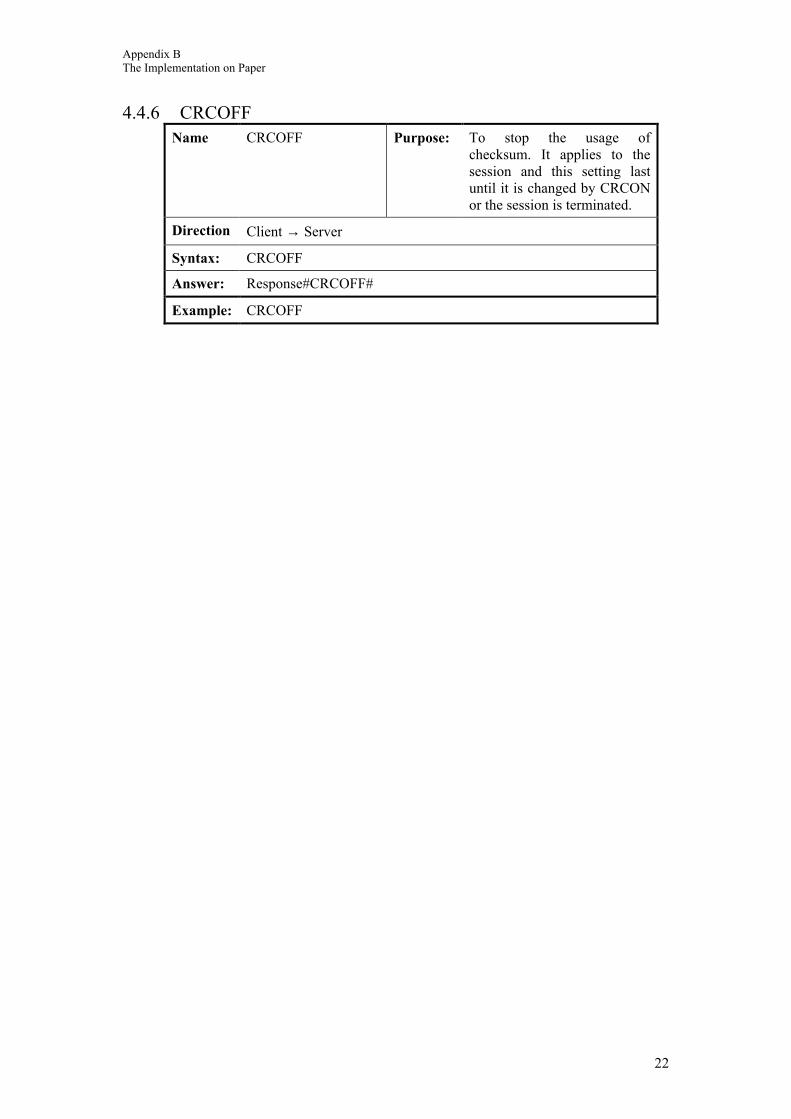
Appendix B The Implementation on Paper
22
4.4.6 CRCOFF Name CRCOFF Purpose: To stop the usage of
checksum. It applies to the session and this setting last until it is changed by CRCON or the session is terminated.
Direction Client → Server
Syntax: CRCOFF
Answer: Response#CRCOFF#
Example: CRCOFF