Embed Size (px)
Citation preview
Improvement of Buck Converter Performance
Using Artificial Bee Colony Optimized-PID
Controller
Yusuf Sonmez1, Ozcan Ayyildiz
1, H. Tolga Kahraman
2, Ugur Guvenc
3, and Serhat Duman
3
1 Department of Electrical and Energy, Gazi Vocational College, Gazi University, Turkey
2 Department of Software Engineering, Technology Faculty, Karadeniz Technical University, Turkey
3 Department of Electrical and Electronics Engineering, Technology Faculty, Duzce University, Turkey
Email: ysonmez, [email protected], [email protected], ugurguvenc, [email protected]
Abstract—In this study, Artificial Bee Colony (ABC)
algorithm is proposed to determine gain parameters of the
PID algorithm for controlling a designed buck converter.
Study aims to improve the performance of buck converter
via ABC-PID. Genetic Algorithm (GA) based PID is used
also to control the converter in order to investigate the
performance of the proposed algorithm on the system.
Experiments with different cases are done via simulations.
In the simulations, settling time, steady-state error and
readjustment time of output voltage in cases of load
variation are analyzed in order to determine the
performance of the proposed algorithm. Results obtained
from simulations are shows that ABC-PID controlled
converter has superior performance than GA-PID
controlled buck converter.
Index Terms—artificial bee colony algorithm, PID, buck
converter
I. INTRODUCTION
Dc-dc converters are widely used power electronics
components in industrial area like switching mode power
supply (SMPS), personal computer, dc motor drives, etc.
The input of the dc-dc converters is unregulated dc
voltage obtained by the rectifying line-voltage and a
converter converts this input into a regulated dc output
voltage at a desired level. Buck converter is used to
decrease the output voltage level in proportion to input
and so it is called or known as step-down converter also.
Since dc-dc converters have power devices, effect of
switching and passive components like inductors and
capacitors, they are non-linear systems [1], [2]. Therefore,
control methods used to control the converters directly
affect the performance of the converter.
Various control methods have used to control the
output voltage of dc-dc converters such as pole placement
[3], LQR [4], feedback loop [5], state space control [6]. A
powerful method to control the converters is PID control.
Since it is easy to design and implementation to a system,
most of the time chosen by practitioners. However,
choosing of PID gain parameters is hard because of dc-dc
Manuscript received July 1, 2014; revised September 26, 2014.
converters contains parasitic components and changes in
input voltage and output load by the time [7]. Therefore,
PID gain parameters must be designed effectively by
using strong methods in order to obtain a robust transient
response. First time, various classical methods [8], [9] or
Ziegler-Nichols (ZN) [10] are used to perform this
operation. These classical methods have some
disadvantages such as the necessity of complex
mathematical computation, producing huge overshoot
and unsatisfactory phase and gain margins. In recent years, artificial intelligence and optimization
techniques have been used frequently in designing of PID depending on development of these methods. Algorithms like Fuzzy Logic (FL) [11], [12], Particle Swarm Optimization (PSO) [13], [14], Bacterial Foraging Optimization (BFO) [15], [16] or Genetic Algorithm (GA) [17], [18] have been implemented to determining the PID gain parameters successfully. However, they have had inadequate in some solution process due to reasons like difficulty of creating fuzzy rules in fuzzy logic, premature convergence or long computing time.
Artificial Bee Colony (ABC) which was proposed by Karaboğa [19] has a simple structure, less control parameters and gives strong solutions for different fitness functions when compared to other optimization algorithms like GA and PSO [20]. Therefore, in this study, ABC is used to determine the PID gain parameters for controlling the Buck Converter. The performances of the controller optimized by ABC are compared in simulation in accordance with overshoot, undershoot, rise time, settling time, and steady state error. Results obtained from ABC are compared the GA in order to evaluate the performance of proposed algorithm.
The rest of the paper organized as follows. In Section
2, the mathematical model of the buck converter is
presented. In Section 3, ABC-PID control schema of the
converter is expressed. Experimental results are given in
Section 4, and Section 5 contains conclusion of the study.
II. MATHEMATICAL MODEL OF THE BUCK
CONVERTER
As the simplest form of a SMPS circuit, a Buck
Converter converts the unregulated input voltage into
304©2015 Engineering and Technology Publishing
Journal of Automation and Control Engineering Vol. 3, No. 4, August 2015
doi: 10.12720/joace.3.4.304-310

regulated output voltage which is lower level than input.
A basic Buck Converter model is shown In Fig. 1. A
buck converter contains a switch, a diode, an inductor, a
capacitor and a load resistance. According to Fig. 1, the
switch (S) choppers the input voltage at high frequency
and converts the input voltage with constant amplitude to
rectangular waveform. Then average DC output voltage
Vo is obtained from this rectangular waveform by passing
through low-pass filter formed from inductor and
capacitor. The turning-on time of the switch (ton) during
one switching period (Ts) is called duty ratio (D) and Vo is
controlling by changing D. These formulations are
illustrated in Eq. 1.
A buck converter circuit has two operating mode
according to cases of the switch. In first mode, when the
switch is on, the input source provides energy to the L, C
and R and the input current passing through these
components.
L RL
C
RC
R
S
Vi
+
-
iL
VO
VC
iC
iO
Figure 1. The equivalent circuit of the buck converter
s
on
T
tD and
io VDV (1)
The inductor current is equal to the input current and
shows an increasing tendency. In second mode, when the
switch is off, the inductor provides the own energy stored
at previous mode to the L, C and R and the inductor
current passing through these components. The inductor
current shows a decreasing tendency at this mode.
Mathematical model of the buck converter can be defined
as follows according to both modes.
When the switch is on:
C
C
C
C
C
LL
iL
RR
R
Lv
RR
RRR
Li
L
V
dt
di1
11
(2)
C
C
C
L
C
RRCv
RR
R
Ci
dt
dv 111 (3)
When the switch is off:
C
C
C
C
C
LL
L
RR
R
Lv
RR
RRR
Li
dt
di1
11
(4)
C
C
C
L
C
RRCv
RR
R
Ci
dt
dv 111 (5)
where Vi is the input voltage, RL is the inductor
resistance, Rc is the capacitor resistance, iL is the inductor
current, vc is the capacitor voltage, L is the inductor, C is
the capacitor and R is the load resistance.
III. ABC-PID BASED CONTROL OF THE BUCK
CONVERTER
The output voltage of the buck converter can be kept at
a stable value by using the PID controller structure. A
basic diagram of PID control model for buck converter is
shown in Fig. 2. Difference between the output voltage of
the converter and a desired voltage value are known as
error (in Eq. 6) and it is input of the PID controller.
Controller computes a control variable value (PID output,
in Eq. 7) by using its gain parameters and error value and
this control variable value feds the Pulse Width
Modulation (PWM) generator. PWM generator produces
the switching signal for switch located on the converter
by comparing the PID output and a saw-tooth waveform.
This process can be modeled mathematically as described
in Eq. 6 and Eq. 7.
tVVte oref (6)
dt
tdeKdtteKteKtu d
t
ip 0
(7)
where e(t) is the error, Vref is the reference voltage, Vo(t)
is the converter output voltage, Kp is the proportional
parameter, Ki is the integral parameter, Kd is the
derivative parameter and u(t) is the output (control
variable) of the PID controller . In the PID control, Kp effects the rise time, Ki reduce
the steady state error and Kd is used to reduce the overshoot and improve the stability.[14, 15].These controller parameters are defined optimally in the control system to make the system stability and obtain an effective or robust transient response. As can be seen from Fig. 2, in this study, ABC algorithm is used to define the PID parameters optimally. This optimization process is explained below.
A. Application of Artificial Bee Colony Algorithm to
Optimize the PID Controller
ABC is a robust optimization method proposed by Karaboğa [19] inspiring by foraging behavior of honey bees. In the ABC, algorithm artificial bees which are employed, onlooker and scout search the food source which has the highest nectar amount by modifying the food positions by time. In the ABC, while a possible solution of the problem corresponds to position of a food source, fitness of the association solution corresponds to nectar amount of this source. ABC algorithm works at 10 steps described below [21].
305©2015 Engineering and Technology Publishing
Journal of Automation and Control Engineering Vol. 3, No. 4, August 2015

TABLE I. LIMITS OF THE PID PARAMETERS
PID controller
parameters
Range
Minimum Maximum
Kp 0 200
Ki 0 10
Kd 0 0.01
Step1: Input data
Limits of PID parameters are read at this step. In this
study used limits belong to PID parameters are given in
Table I.
Step 2: Initialization
ABC parameters like colony dimension, maximum
cycle number, number of variables and limit parameter
are initialized.
Kp
Ki
Kddt
d
dt
PID Controller
+++
PWM Buck Converter+ -
VO
VOVref e(t)
Artificial Bee Colony Algorithm
Kp Ki Kd
u(t)
Switching
Pulse
Figure 2. ABC-PID control model the buck converter
Step 3: Initialization of population
A set of initial population with N solutions xi
(i=1,2,…N) is produced randomly and their fitness are
determined. Here each solution of xi represented by D-
dimensional vector corresponded to number of PID
parameters optimized.
Step 4: Fitness evaluation of the population
Fitness values obtained from the fitness function
belong to each solution is evaluated at this step. The
fitness function used in this study is described as follows.
k
t
i tefit1
2 (8)
where e(t) is the error value described in Eq. 6 and k is
the maximum iteration number in simulation of operating
buck converter for determined PID parameters at one
cycle of ABC algorithm.
Step 5: Set the cycle counter to 1
Step 6: Modification of food source positions
(solutions)
Food sources are modified and replaced by a new one
via employed bees. Then the nectar amounts of the new
sources are tested. If the nectar amount of the new source
is better than old one, the new food source are kept the
memory, otherwise it discards. This modification process
of food sources are described as follows.
DjandNkxxxv kjijijijij ,...,2,1,...,2,1 (9)
where vij is the new food source position, k and j are
randomly determined indexes, βij is a number determined
randomly interval of [-1,1].
Step 7: Employing of onlookers and calculation of
probabilities
Employed bees share the nectar amount and position
information of food sources with onlookers waiting at the
dance area after completing the search process. Onlooker
bees prefer a food source according to a probability value
Pi described as follows.
N
j
j
i
i
fit
fitP
1
(10)
where fiti is the fitness value of the i-th solution described
in Eq. 8 and N is the total number of food sources. Then,
at this step, onlooker bees modify the food sources given
in Eq. 9 and test the nectar amount as in the case of Step
6.
Step 8: Abandoning from the exploited source
At this step, if a food source is not improved further
that source is abandoned and it replaced with a new one
by scout bees. In the ABC, this process is done according
to the “limit” parameter which is predetermined number
of cycles for abandoning the food source. Discovering a
new food source by a scout is described as follows.
jjjj
i xxrandxx minmaxmin 1,0 (11)
xjmin and xj
max are minimum and maximum limits of the
parameter to be optimized.
Step 9: Memorize the best solution so far
Step 10: Increase the cycle counter
Step 11: Stopping the algorithm
Steps between 6 and 10 are repeated until reach the
Maximum Cycle Number (MCN) determined before.
Then, the searching process is stopped.
IV. EXPERIMENTAL RESULTS
306©2015 Engineering and Technology Publishing
Journal of Automation and Control Engineering Vol. 3, No. 4, August 2015
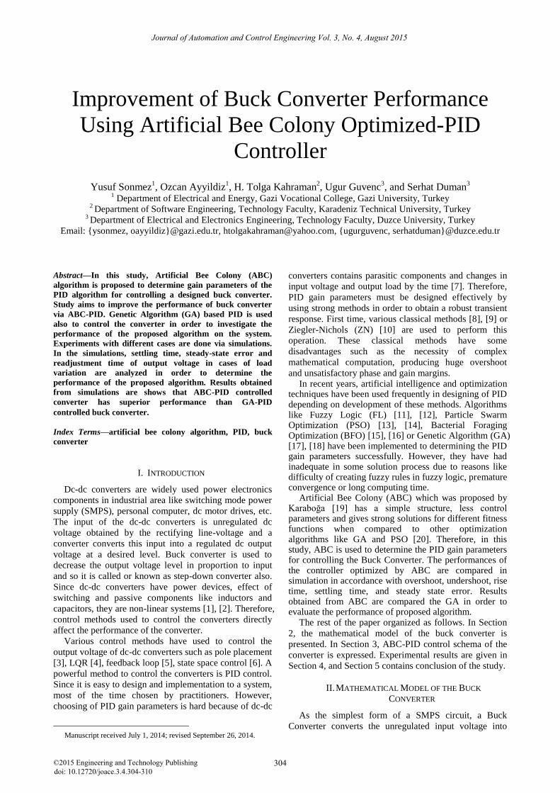
In this study, control of the buck converter is simulated
by using ABC-PID algorithm in order to investigate
performance of the proposed algorithm. GA based PID
algorithm is also implemented on the same converter and
obtained results are compared with GA-PID algorithm to
show the effectiveness of the ABC-PID. Simulation of
experiments is done via C# language in Visual Studio.
Buck converter parameters used in simulation are listed
in Table II, ABC parameters used in simulation are given
in Table III and PID parameters produced by ABC and
GA are given in Table IV.
TABLE II. PARAMETERS OF THE BUCK CONVERTER
Parameter Value
Vi 12 V
RL 0.13 Ω
RC 0.03 Ω
R 2 Ω
L 270 µH
C 1000 µF
(a)
(b) (c)
Figure 3. Simulation results
of the GA-PID controlled buck converter
TABLE III. ABC PARAMETERS
ABC Parameters Values
Colony dimension 86
Maximum cycle number 5000
Number of variables 3
Limit parameter 0.006
In Fig. 3(a), output waveform of GA-PID controlled
buck converter is given. Fig. 3(b) and Fig. 3(c) are
zoomed version of Fig. 3(a). The settling time is 0.01 ms
as seen in Fig. 3(b) and steady-state error is 12 mV as
seen in Fig. 3(c) for GA-PID control. In Fig. 4(a) output
waveform of ABC-PID controlled buck converter is
given. Fig. 4(b) and Fig. 4(c) are zoomed version of Fig.
4(a) also. The settling time is 0.0045 ms as seen in Fig.
4(b) and steady-state error is 3.9 mV as seen in Fig. 4(c)
for ABC-PID control. It is clearly seen that these results
ABC-PID algorithm produces more robust results to
control the buck converter from the point of settling time
and steady-state error.
In the experiment, the load resistor is changed 2 Ω to
10 Ω at 0.5 ms. Fig. 5(a) shows the output waveform of
GA-PID controlled converter in this case.
Fig. 5(b) is
zoomed version of Fig. 5(a). The GA-PID controller
regulates the voltage increase with 0.14 V in 0.009 ms for
this case.
Fig. 6(a) shows the output waveform of ABC-
PID controlled converter for the same case.
307©2015 Engineering and Technology Publishing
Journal of Automation and Control Engineering Vol. 3, No. 4, August 2015
TABLE IV. PID PARAMETERS OBTAINED FROM OPTIMIZATION
ALGORITHMS
Algorithms
Gain Parameters
P
(Proportional)D (Derivative) I (Integral)
GA 26 0.055 0.0037
ABC 94 0.097 0.0051

(a)
(b) (c)
Figure 4. Simulation results of the ABC-PID controlled buck converter
(a) (b)
Figure 5. Simulation results of the GA-PID controlled buck converter; R=2 Ω to R=10 Ω at 0.5 ms
(a) (b)
Figure 6. Simulation results of the ABC-PID controlled buck converter; R=2 Ω to R=10 Ω at 0.5 ms
308©2015 Engineering and Technology Publishing
Journal of Automation and Control Engineering Vol. 3, No. 4, August 2015
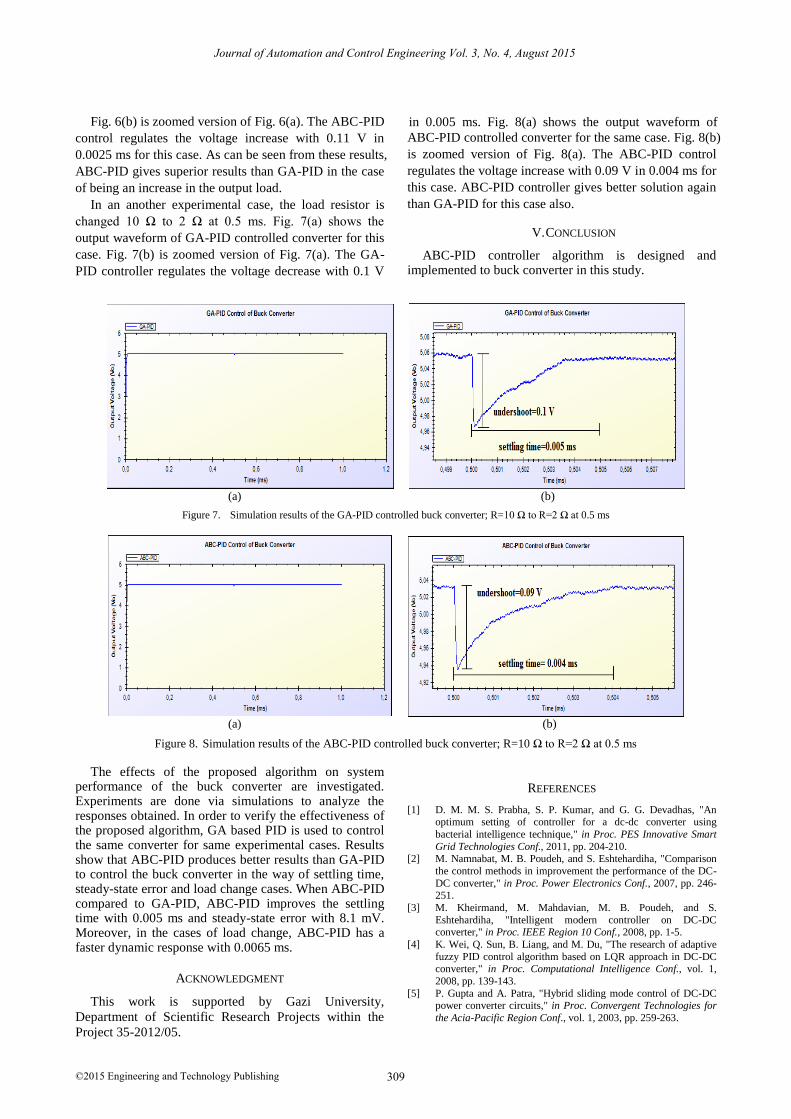
Fig. 6(b) is zoomed version of Fig. 6(a). The ABC-PID
control regulates the voltage increase with 0.11 V in
0.0025 ms for this case. As can be seen from these results,
ABC-PID gives superior results than GA-PID in the case
of being an increase in the output load.
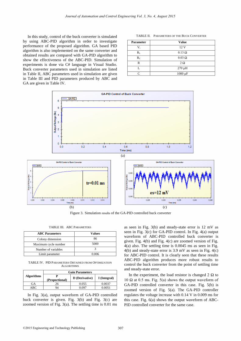
In an another experimental case, the load resistor is
changed 10 Ω to 2 Ω at 0.5 ms. Fig. 7(a) shows the
output waveform of GA-PID controlled converter for this
case. Fig. 7(b) is zoomed version of Fig. 7(a). The GA-
PID controller regulates the voltage decrease with 0.1 V
in 0.005 ms. Fig. 8(a) shows the output waveform of
ABC-PID controlled converter for the same case. Fig. 8(b)
is zoomed version of Fig. 8(a). The ABC-PID control
regulates the voltage increase with 0.09 V in 0.004 ms for
this case. ABC-PID controller gives better solution again
than GA-PID for this case also.
V. CONCLUSION
ABC-PID controller algorithm is designed and implemented to buck converter in this study.
(a) (b)
Figure 7. Simulation results of the GA-PID controlled buck converter; R=10 Ω to R=2 Ω at 0.5 ms
(a) (b)
Figure 8. Simulation results of the ABC-PID controlled buck converter; R=10 Ω to R=2 Ω at 0.5 ms
The effects of the proposed algorithm on system performance of the buck converter are investigated. Experiments are done via simulations to analyze the responses obtained. In order to verify the effectiveness of the proposed algorithm, GA based PID is used to control the same converter for same experimental cases. Results show that ABC-PID produces better results than GA-PID to control the buck converter in the way of settling time, steady-state error and load change cases. When ABC-PID compared to GA-PID, ABC-PID improves the settling time with 0.005 ms and steady-state error with 8.1 mV. Moreover, in the cases of load change, ABC-PID has a faster dynamic response with 0.0065 ms.
ACKNOWLEDGMENT
This work is supported by Gazi University,
Department of Scientific Research Projects within the
Project 35-2012/05.
REFERENCES
[1] D. M. M. S. Prabha, S. P. Kumar, and G. G. Devadhas, "An optimum setting of controller for a dc-dc converter using
bacterial intelligence technique," in Proc. PES Innovative Smart
Grid Technologies Conf., 2011, pp. 204-210. [2] M. Namnabat, M. B. Poudeh, and S. Eshtehardiha, "Comparison
the control methods in improvement the performance of the DC-
DC converter," in Proc. Power Electronics Conf., 2007, pp. 246-251.
[3] M. Kheirmand, M. Mahdavian, M. B. Poudeh, and S.
Eshtehardiha, "Intelligent modern controller on DC-DC converter," in Proc. IEEE Region 10 Conf., 2008, pp. 1-5.
[4] K. Wei, Q. Sun, B. Liang, and M. Du, "The research of adaptive
fuzzy PID control algorithm based on LQR approach in DC-DC converter," in Proc. Computational Intelligence Conf., vol. 1,
2008, pp. 139-143.
[5] P. Gupta and A. Patra, "Hybrid sliding mode control of DC-DC power converter circuits," in Proc. Convergent Technologies for
the Acia-Pacific Region Conf., vol. 1, 2003, pp. 259-263.
309©2015 Engineering and Technology Publishing
Journal of Automation and Control Engineering Vol. 3, No. 4, August 2015

[6] G. Keller, D. Lascu, and J. M. A. Myrzik, "State-space control structures for buck converters with/without input filter," in Proc.
Power Electronics and Applications Conf., 2005, pp. 1-10.
[7] İ. Atacak and Ö. F. Bay, "Tuning gain parameters of a PI controller using genetic algorithm for boost dc-dc converter," in
Proc. International Advanced Technologies Symp., 2009, pp.
221-225. [8] H. N. Koivo, "Tuning of a multivariable PID-controller for
unknown systems," in Proc. IEEE Decision and Control
Including the Symposium on Adaptive Processes Conf., vol. 19, 1980, pp. 1158-1159.
[9] D. M. Bain and G. D. Martin, "Simple PID tuning and PID-
closed loop simulation," in Proc. American Control Conference Conf., 1983, pp. 338-341.
[10] J. G. Ziegler, N. B. Nichols, and N. Y. Rochester, "Optimum
settings for automatic controllers," Transactions of the ASME, vol. 64, pp. 759-768, 1942.
[11] A. Diordiev, O. Ursaru, M. Lucanu, and L. Tigaeru, "A hybrid
fuzzy-PID controller for dc-dc converters," in Proc. Signals,
Circuits and Systems Conf., vol. 1, 2003, pp. 97-100, 2003.
[12] L. Guo, J. Y. Hung, and R. M. Nelms, "Evaluation of DSP-based
PID and fuzzy controllers for dc–dc converters," IEEE Transactions on Industrial Electronics, vol. 56, no. 6, pp. 2237-
2248, 2009.
[13] O. T. Altinoz and H. Erdem, "Evaluation function comparison of particle swarm optimization for buck converter," in Proc. Power
Electronics, Electrical Drives, Automation and Motion conf.,
2010, pp. 798-802. [14] M. R. Yousefi, M. B. Poudeh, and S. Eshtehardiha,
"Improvement performance of step-down converter through
intelligent controllers," in Proc. IEEE Intelligent Systems Conf., vol. 4, 2008, pp. 20-24.
[15] A. Jalilvand, H. Vahedi, and A. Bayat, "Optimal tuning of the
PID controller for a buck converter using bacterial foraging algorithm," in Proc. Intelligent and Advanced Systems Conf.,
2010, pp. 1-5.
[16] D. M. M. S. R. Prabha, S. P. Kumar, and G. G. Devedhas, "An optimum setting of controller for a dc-dc converter using
bacterial intelligence technique," in Proc. Innovative Smart Grid Technologies Conf., 2011, pp. 204-210.
[17] C. Ou and W. Lin, “Comparison between PSO and GA for
parameters optimization of PID controller,” in Proc. IEEE Mechatronics and Automation Conf., 2006, pp. 2471-2475.
[18] C. H. Cheng, P. J. Cheng, and M. J. Xie, "Current sharing of
paralleled DC–DC converters using GA-based PID controllers," Expert Systems with Applications, vol. 37, pp. 733-740, 2010.
[19] D. Karaboga, "An idea based on honey bee swarm for numerical
optimization," Technical Report-TR06, Erciyes University, Engineering Faculty, Computer Engineering Department, 2005.
[20] D. Karaboga and B. Akay, "A comparative study of artificial bee
colony algorithm," Applied Mathematics and Computation, vol. 214, pp. 108-132, 2009.
[21] Y. Sönmez, "Estimation of fuel cost curve parameters for thermal
power plants using ABC," Turkish Journal of Electrical Engineering and Computer Science, vol. 21, pp. 1827-1841, 2013.
Yusuf Sönmez was born in Ankara,
Turkey in 1980. He received the BS
degree in electrical and electronics
education and the MSc degree in
e l e c t r i c a l e d u c a t i o n f r o m G a z i
University, Ankara, Turkey, in 2002 and
2005, respectively, and the PhD degree
in electronic and electrical engineering
from the Gazi University, Ankara,
Turkey, in 2008. He is a research assistant with Gazi University,
Gazi Vocational College from 2004. His research interests
include power systems, electrical machines and drives,
intelligent control, artificial intelligence and optimization
techniques.
Ozcan Ayyıldız received the BS degree in
electrical and electronics education from
Fırat University, Elazığ, Turkey, in 1998.
He is a lecturer with Gazi University, Gazi
Vocational College. from 2005. His
research interests include power
electronics, electrical machines and drives.
H. Tolga Kahraman was born in Trabzon,
Turkey, in 1979. He received the B.Sc.
degree in electrical education from Gazi
University, Ankara, Turkey in 2002, M.Sc.
degree from Gazi University, Turkey in
2005 and the Ph.D. degree from Gazi
Universi ty, Turkey in 2009. He is
currently an Assistance Professor in the
Department of Software Engineering,
Faculty of Technology, Karadeniz Technical University, Turkey.
His main interests are in artificial intelligent, object oriented
programming and numerical analysis.
Ugur Guvenc was born in Zile, Turkey,
in 1980. He received the B.Sc. degree in
electrical education from Abant İzzet
Baysal University, Bolu, Turkey in 2002,
M.Sc. degree from Gazi University,
Turkey in 2005 and the Ph.D. degree from
Gazi University, Turkey in 2008. He is
currently an Assistance Professor in the
Department of Electrical Education,
Faculty of Technical Education, Duzce
University, Turkey. His main interests are in artificial intelligent,
power system and image processing.
Serhat Duman was born in Bandırma,
Turkey, in 1981. He received the B.Sc.
degree in electrical education from Abant
Izzet Baysal University, Bolu, Turkey, in
2 0 08 an d M.Sc . d egree f ro m th e
Department of Electrical Education,
Duzce University, Duzce, Turkey in 2010.
He is currently student of Ph.D. in the
Department of Electrical Engineering,
Kocaeli University, Turkey. His areas of research include power
system transient stability, power system dynamic stability,
FACTS, optimization techniques, voltage stability, optimization
problems in power systems and artificial intelligent.
310©2015 Engineering and Technology Publishing
Journal of Automation and Control Engineering Vol. 3, No. 4, August 2015