Embed Size (px)
Citation preview

International Research Journal of Engineering and Technology (IRJET) e-ISSN: 2395 -0056
Volume: 03 Issue: 01 | Jan-2016 www.irjet.net p-ISSN: 2395-0072
© 2016, IRJET | Impact Factor value: 4.45 | ISO 9001:2008 Certified Journal | Page 1259
Improvement in Accuracy, Through Turning Operation by Using SPKN
1203 EDR Tool Bit For Different Steel Materials
Doneti Gopi krishna1, Dr. Dipak Rajan Jana2, Sravan Sashank3
1 M.Tech Student, Design for Manufacturing, G.R.I.E.T, Telangana, India 2 Professor & Director, Mechanical Department, A.H.T.C, Telangana, India 3 Assistant Professor, Mechanical Department, G.R.I.E.T, Telangana, India
---------------------------------------------------------------------***---------------------------------------------------------------------
Abstract - Now a day’s getting high quality with low
cost with higher accuracy gives not only customer (Both
Internal & External) satisfaction but also improves the
economic condition of that company intern that country
and globally. Many key factors like type of tool bit and
its setting angle, machining conditions, the type of
material to be machined, spindle speed, cutting speed
and feed rate etc., play an important role in Turning for
getting Accuracy of the product Dimensions and Surface
Finish. Hence In this study, on lathe Machine Turning
operation carried out for different Steel materials such
as Mild Steel, EN-8, EN-3 and OHNS by using HSS tool bit
first and then second by using SPKN 1203 EDR tool bit
with constant Cutting speed, time, feed and depth of cut.
Measurements of the machined components have been
taken and the collected data analyzed by using SQC
chart.
First of all the problem has been defined and
established through Histogram followed by Pareto
Analysis, and then Cause and Effect Analysis. The
problem has been investigated through Ishikawa (Fish
bone) diagram and finally preventive and corrective
action has been taken for accuracy improvement in
turning operation. By the Comparison of both the tool
bits, concluded that SPKN 1203 EDR tool bit is the better
one in terms of obtaining higher accuracy and surface
finish for different steel materials.
Key Words: Accuracy, Stastical Quality Control (SQC)
Chart, Histogram, Pareto Analysis, Cause and Effect Analysis
1. INTRODUCTION As we know type of tool bit plays a vital role in perfect machining for getting accuracy and surface finish and also most desirable finish. Tool Setting angle [1] and machining conditions also plays an important role for getting higher
accuracy. Tool wear for harder material in turning not only modifies the cutting edge geometry but also increases cutting forces and cutting temperature significantly, which in turn, influence the residual stress profile on the machine surface. This study focuses on the improvements in turning operation of different steel materials and type tool bit to be used for getting Accuracy of the product and how much deviation from the mean value of the required dimension, and also focuses on the surface finish. Four different steel materials with different carbon percentage have been taken for the turning operation. First by using HSS tool bit for constant spindle speed, time, feed and depth of cut turning has been out for all the materials and then with the same machining conditions SPKN tool bit is used for the materials. Collected data for five observations have been analyzed by using SQC chart. The defects caused by Tool positioning and its alignment with cutting axis, Machine vibrations, Machine bed servicing, Head stock, Tail stock, carriage Tool post, Carriage, Gears, Belt drives and Leveling of machine [2] have been analyzed with Histograms followed by Pareto and Cause &effect analysis. Remedy has been for higher accuracy and surface finish.
1.1 Accuracy
Accuracy is a level of measurement that yields true (no systematic errors) and consistent (no random errors) results. It always closer to the Nominal Value and it associate with the Job/Work.
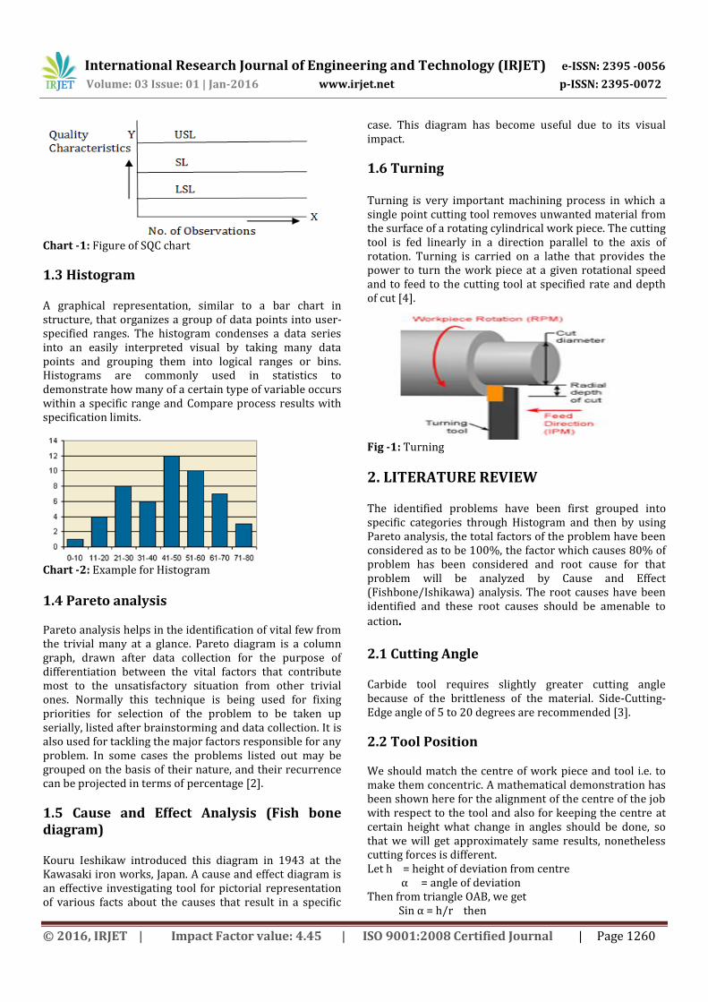
1.2 Stastical Quality Control (SQC) chart The SQC chart consisting of three Horizontal lines drawn on X & Y axis, where the ‘X’ axis shows the number of observations and ‘Y’ axis shows the quality Characteristics. Hence out of three horizontal lines, where the upper one is known as Upper Specification Limit (USL), and the middle one is known as Specification Limit (SL),and the Lower one is known as Lower Specification Limit (LSL).
International Research Journal of Engineering and Technology (IRJET) e-ISSN: 2395 -0056
Volume: 03 Issue: 01 | Jan-2016 www.irjet.net p-ISSN: 2395-0072
© 2016, IRJET | Impact Factor value: 4.45 | ISO 9001:2008 Certified Journal | Page 1260
Chart -1: Figure of SQC chart
1.3 Histogram A graphical representation, similar to a bar chart in structure, that organizes a group of data points into user-specified ranges. The histogram condenses a data series into an easily interpreted visual by taking many data points and grouping them into logical ranges or bins. Histograms are commonly used in statistics to demonstrate how many of a certain type of variable occurs within a specific range and Compare process results with specification limits.
Chart -2: Example for Histogram
1.4 Pareto analysis Pareto analysis helps in the identification of vital few from the trivial many at a glance. Pareto diagram is a column graph, drawn after data collection for the purpose of differentiation between the vital factors that contribute most to the unsatisfactory situation from other trivial ones. Normally this technique is being used for fixing priorities for selection of the problem to be taken up serially, listed after brainstorming and data collection. It is also used for tackling the major factors responsible for any problem. In some cases the problems listed out may be grouped on the basis of their nature, and their recurrence can be projected in terms of percentage [2].
1.5 Cause and Effect Analysis (Fish bone diagram) Kouru Ieshikaw introduced this diagram in 1943 at the Kawasaki iron works, Japan. A cause and effect diagram is an effective investigating tool for pictorial representation of various facts about the causes that result in a specific
case. This diagram has become useful due to its visual impact.
1.6 Turning Turning is very important machining process in which a single point cutting tool removes unwanted material from the surface of a rotating cylindrical work piece. The cutting tool is fed linearly in a direction parallel to the axis of rotation. Turning is carried on a lathe that provides the power to turn the work piece at a given rotational speed and to feed to the cutting tool at specified rate and depth of cut [4].
Fig -1: Turning
2. LITERATURE REVIEW
The identified problems have been first grouped into specific categories through Histogram and then by using Pareto analysis, the total factors of the problem have been considered as to be 100%, the factor which causes 80% of problem has been considered and root cause for that problem will be analyzed by Cause and Effect (Fishbone/Ishikawa) analysis. The root causes have been identified and these root causes should be amenable to
action. 2.1 Cutting Angle Carbide tool requires slightly greater cutting angle because of the brittleness of the material. Side-Cutting-Edge angle of 5 to 20 degrees are recommended [3].
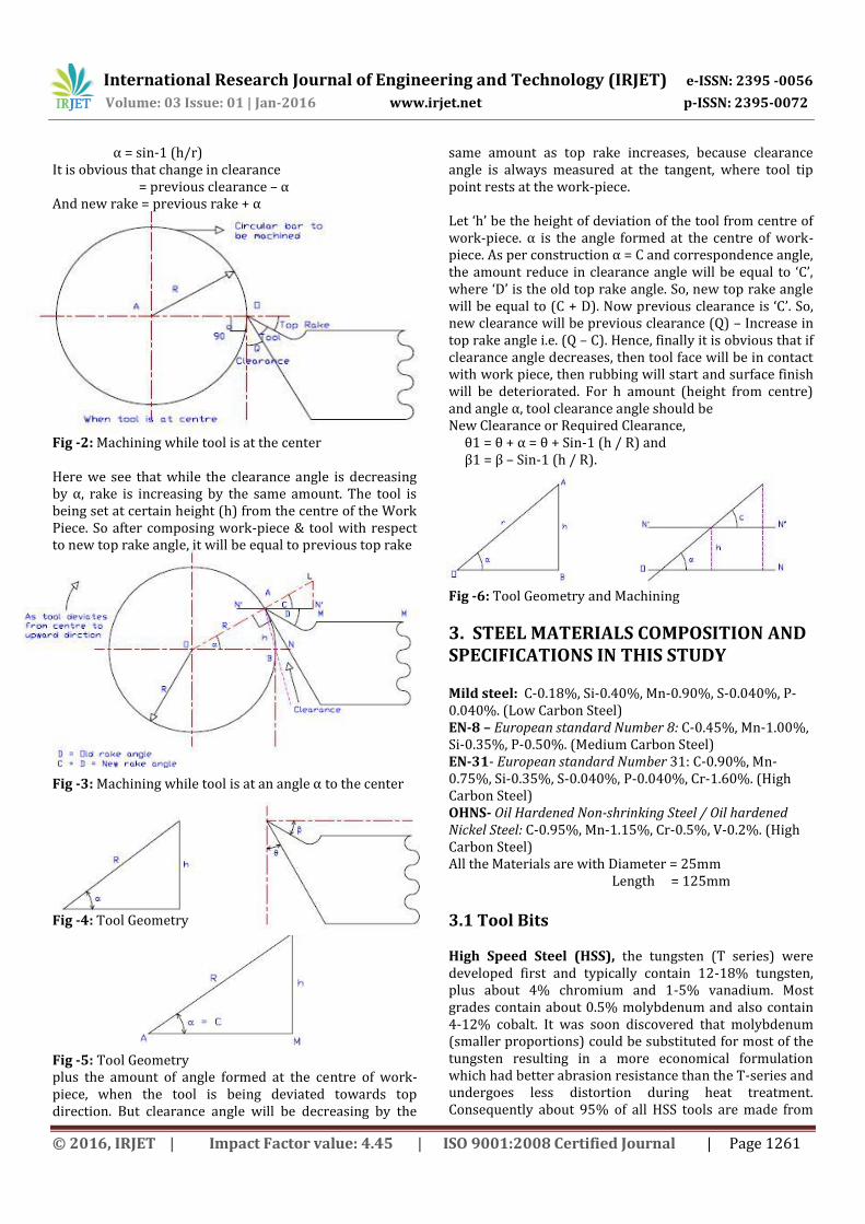
2.2 Tool Position We should match the centre of work piece and tool i.e. to make them concentric. A mathematical demonstration has been shown here for the alignment of the centre of the job with respect to the tool and also for keeping the centre at certain height what change in angles should be done, so that we will get approximately same results, nonetheless cutting forces is different. Let h = height of deviation from centre α = angle of deviation Then from triangle OAB, we get Sin α = h/r then
International Research Journal of Engineering and Technology (IRJET) e-ISSN: 2395 -0056
Volume: 03 Issue: 01 | Jan-2016 www.irjet.net p-ISSN: 2395-0072
© 2016, IRJET | Impact Factor value: 4.45 | ISO 9001:2008 Certified Journal | Page 1261
α = sin-1 (h/r) It is obvious that change in clearance = previous clearance – α And new rake = previous rake + α Fig -2: Machining while tool is at the center Here we see that while the clearance angle is decreasing by α, rake is increasing by the same amount. The tool is being set at certain height (h) from the centre of the Work Piece. So after composing work-piece & tool with respect to new top rake angle, it will be equal to previous top rake Fig -3: Machining while tool is at an angle α to the center Fig -4: Tool Geometry
Fig -5: Tool Geometry plus the amount of angle formed at the centre of work-piece, when the tool is being deviated towards top direction. But clearance angle will be decreasing by the
same amount as top rake increases, because clearance angle is always measured at the tangent, where tool tip point rests at the work-piece. Let ‘h’ be the height of deviation of the tool from centre of work-piece. α is the angle formed at the centre of work-piece. As per construction α = C and correspondence angle, the amount reduce in clearance angle will be equal to ‘C’, where ‘D’ is the old top rake angle. So, new top rake angle will be equal to (C + D). Now previous clearance is ‘C’. So, new clearance will be previous clearance (Q) – Increase in top rake angle i.e. (Q – C). Hence, finally it is obvious that if clearance angle decreases, then tool face will be in contact with work piece, then rubbing will start and surface finish will be deteriorated. For h amount (height from centre) and angle α, tool clearance angle should be New Clearance or Required Clearance, θ1 = θ + α = θ + Sin-1 (h / R) and β1 = β – Sin-1 (h / R). Fig -6: Tool Geometry and Machining
3. STEEL MATERIALS COMPOSITION AND SPECIFICATIONS IN THIS STUDY Mild steel: C-0.18%, Si-0.40%, Mn-0.90%, S-0.040%, P-0.040%. (Low Carbon Steel) EN-8 – European standard Number 8: C-0.45%, Mn-1.00%, Si-0.35%, P-0.50%. (Medium Carbon Steel) EN-31- European standard Number 31: C-0.90%, Mn-0.75%, Si-0.35%, S-0.040%, P-0.040%, Cr-1.60%. (High Carbon Steel) OHNS- Oil Hardened Non-shrinking Steel / Oil hardened Nickel Steel: C-0.95%, Mn-1.15%, Cr-0.5%, V-0.2%. (High Carbon Steel) All the Materials are with Diameter = 25mm Length = 125mm
3.1 Tool Bits High Speed Steel (HSS), the tungsten (T series) were developed first and typically contain 12-18% tungsten, plus about 4% chromium and 1-5% vanadium. Most grades contain about 0.5% molybdenum and also contain 4-12% cobalt. It was soon discovered that molybdenum (smaller proportions) could be substituted for most of the tungsten resulting in a more economical formulation which had better abrasion resistance than the T-series and undergoes less distortion during heat treatment. Consequently about 95% of all HSS tools are made from
International Research Journal of Engineering and Technology (IRJET) e-ISSN: 2395 -0056
Volume: 03 Issue: 01 | Jan-2016 www.irjet.net p-ISSN: 2395-0072
© 2016, IRJET | Impact Factor value: 4.45 | ISO 9001:2008 Certified Journal | Page 1262
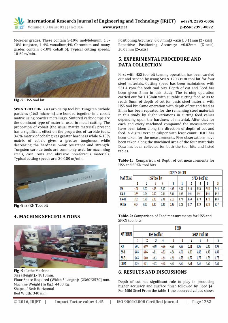
M-series grades. These contain 5-10% molybdenum, 1.5-10% tungsten, 1-4% vanadium,4% Chromium and many grades contain 5-10% cobalt[5]. Typical cutting speeds: 10-60m/min.
Fig -7: HSS tool bit SPKN 1203 EDR is a Carbide tip tool bit. Tungsten carbide particles (1to5 micro-m) are bonded together in a cobalt matrix using powder metallurgy. Sintered carbide tips are the dominant type of material used in metal cutting. The proportion of cobalt (the usual matrix material) present has a significant effect on the properties of carbide tools. 3-6% matrix of cobalt gives greater hardness while 6-15% matrix of cobalt gives a greater toughness while decreasing the hardness, wear resistance and strength. Tungsten carbide tools are commonly used for machining steels, cast irons and abrasive non-ferrous materials. Typical cutting speeds are: 30-150 m/min.
Fig -8: SPKN Tool bit
4. MACHINE SPECIFICATIONS
Fig -9: Lathe Machine Size (Height):- 1810mm. Floor Space Required (Width * Length):-[2360*2570] mm. Machine Weight (In Kg.): 4400 Kg. Shape of Bed: Horizontal Bed Width: 340 mm.
Positioning Accuracy: 0.08 mm[X –axis], 0.11mm [Z -axis] Repetitive Positioning Accuracy: ±0.02mm [X–axis], ±0.03mm [Z–axis]
5. EXPERIMENTAL PROCEDURE AND DATA COLLECTION First with HSS tool bit turning operation has been carried out and second by using SPKN 1203 EDR tool bit for four steel materials. Cutting speed has been maintained with 531.4 rpm for both tool bits. Depth of cut and Feed has been given 5mm in this study. The turning operation carried out for 1.15min with suitable cutting feed so as to reach 5mm of depth of cut for basic steel material with HSS tool bit. Same operation with depth of cut and feed as 5mm has been repeated for the remaining steel materials in this study by slight variations in cutting feed values depending upon the hardness of material. After that for each and every machined compound the measurements have been taken along the direction of depth of cut and feed. A digital vernier caliper with least count ±0.01 has been taken for the measurements. Five observations have been taken along the machined area of the four materials. Data has been collected for both the tool bits and listed tables.
Table-1: Comparison of Depth of cut measurements for HSS and SPKN tool bits
Table-2: Comparison of Feed measurements for HSS and SPKN tool bits
6. RESULTS AND DISCUSSIONS Depth of cut has significant role to play in producing higher accuracy and surface finish followed by Feed [4]. For Mild Steel From the table-1 the observed values shows

International Research Journal of Engineering and Technology (IRJET) e-ISSN: 2395 -0056
Volume: 03 Issue: 01 | Jan-2016 www.irjet.net p-ISSN: 2395-0072
© 2016, IRJET | Impact Factor value: 4.45 | ISO 9001:2008 Certified Journal | Page 1263
that by using HSS tool bit the depth of cut deviated from the mean value i.e., 5mm, with in the accepted limits (5±0.02mm),and also observed values shows that by using SPKN tool bit the depth of cut (doc) has reached higher values than the mean value with ±0.01mm deviation, which shows that the surface finish has been reached the higher accepted limits. Because of the higher hardness of SPKN tool bit than the Mild steel depth of cut values reached the higher values. For the remaining materials with the HSS tool bit depth of cut not at all reached up to the required levels, whereas by using SPKN tool bit depth of cut reached up to the minimum levels, the acceptance levels will be reached by increasing cutting speed and feed rate. From table-2 the observations shows that as material hardness increases, the feed accuracy decreases more for HSS tool bit as compared to the SPKN tool bit.
6.1 SQC Charts and Analysis From the above collected data (Table-1 & Table-2) SQC charts have been prepared only for the Mild steel (MS) material in terms of Depth of cut (doc) and feed for each five measurements, because for the remaining materials depth of cut and feed values are not reached the mean value (i.e., 5mm).
Chart -3: SQC chart for number of observations Vs doc with HSS tool bit (MS)
Chart -4: SQC chart for number of observations Vs doc with SPKN tool bit (MS) From the SQC chart-3 the depth of cut values are deviated from the mean value 5mm with ±0.02mm, whereas from SQC chart-4 the depth of cut values reached the more than mean value (6.5mm) with deviation ±0.01mm. This shows that SPKN tool bit has been given higher surface finish than the HSS tool bit, and due to higher hardness SPKN cut
the more depth of cut than the HSS tool bit for the Mild Steel.
Chart -5: SQC chart for number of observations Vs feed with HSS tool bit (MS)
Chart -6: SQC chart for number of observations Vs feed with SPKN tool bit (MS) From the SQC chart-5 the feed values are deviated from the mean value 5mm with +0.01mm and -0.04mm, whereas from SQC chart-6 that feed values are deviated with ±0.01mm. This shows that SPKN tool bit has been given higher accuracy than the HSS tool bit.
Mild Steel EN-8
EN-31 OHNS Fig -10: Turning with SPKN tool bit
International Research Journal of Engineering and Technology (IRJET) e-ISSN: 2395 -0056
Volume: 03 Issue: 01 | Jan-2016 www.irjet.net p-ISSN: 2395-0072
© 2016, IRJET | Impact Factor value: 4.45 | ISO 9001:2008 Certified Journal | Page 1264
Mild Steel EN-8
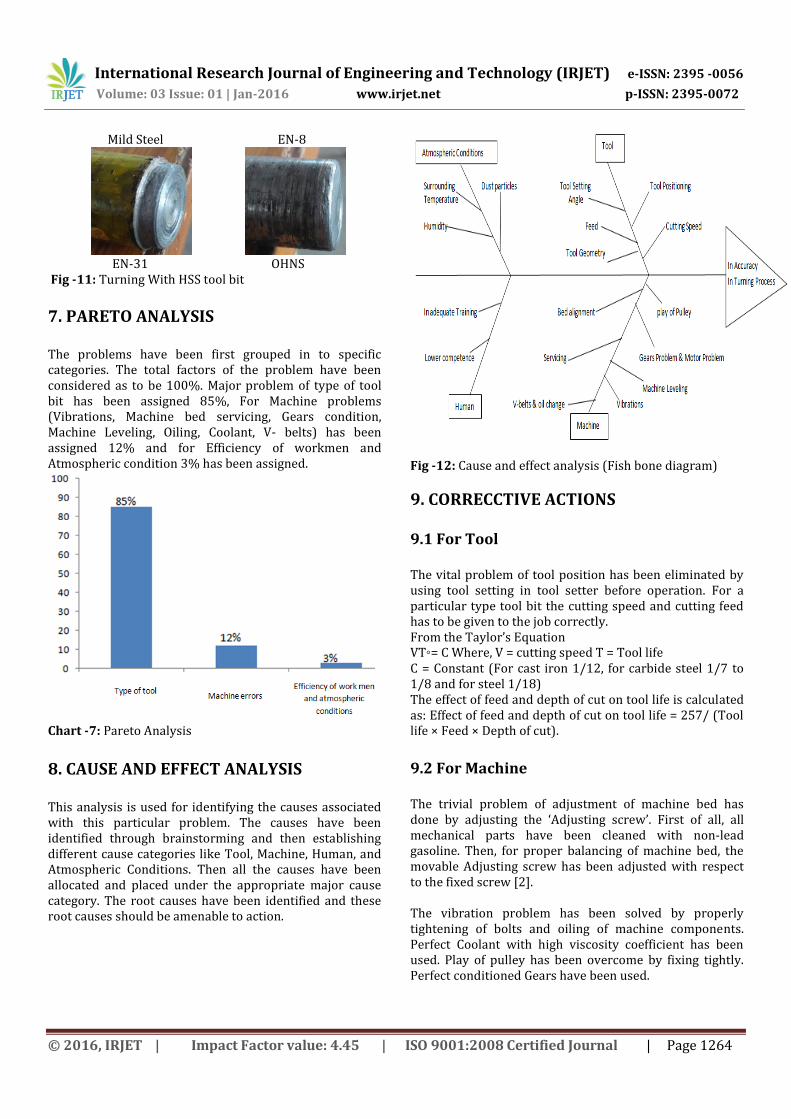
EN-31 OHNS Fig -11: Turning With HSS tool bit
7. PARETO ANALYSIS The problems have been first grouped in to specific categories. The total factors of the problem have been considered as to be 100%. Major problem of type of tool bit has been assigned 85%, For Machine problems (Vibrations, Machine bed servicing, Gears condition, Machine Leveling, Oiling, Coolant, V- belts) has been assigned 12% and for Efficiency of workmen and Atmospheric condition 3% has been assigned.
Chart -7: Pareto Analysis
8. CAUSE AND EFFECT ANALYSIS This analysis is used for identifying the causes associated with this particular problem. The causes have been identified through brainstorming and then establishing different cause categories like Tool, Machine, Human, and Atmospheric Conditions. Then all the causes have been allocated and placed under the appropriate major cause category. The root causes have been identified and these root causes should be amenable to action.
Fig -12: Cause and effect analysis (Fish bone diagram)
9. CORRECCTIVE ACTIONS 9.1 For Tool The vital problem of tool position has been eliminated by using tool setting in tool setter before operation. For a particular type tool bit the cutting speed and cutting feed has to be given to the job correctly. From the Taylor’s Equation VT◦= C Where, V = cutting speed T = Tool life C = Constant (For cast iron 1/12, for carbide steel 1/7 to 1/8 and for steel 1/18) The effect of feed and depth of cut on tool life is calculated as: Effect of feed and depth of cut on tool life = 257/ (Tool life × Feed × Depth of cut).
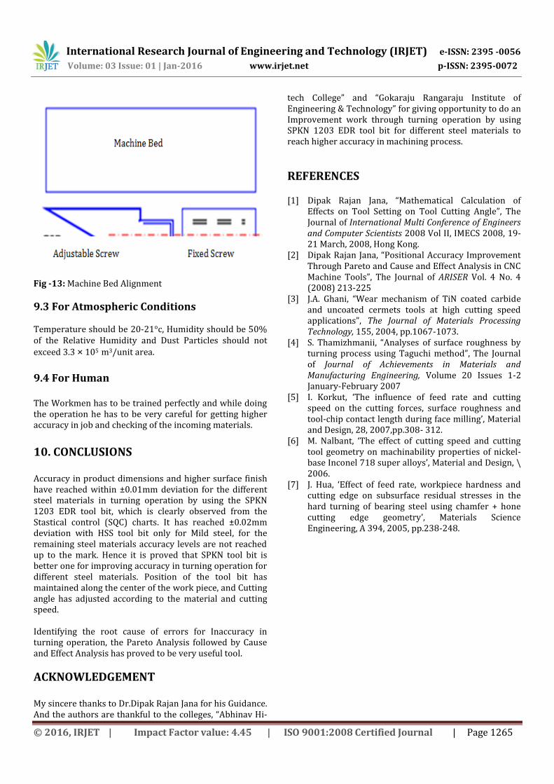
9.2 For Machine The trivial problem of adjustment of machine bed has done by adjusting the ‘Adjusting screw’. First of all, all mechanical parts have been cleaned with non-lead gasoline. Then, for proper balancing of machine bed, the movable Adjusting screw has been adjusted with respect to the fixed screw [2]. The vibration problem has been solved by properly tightening of bolts and oiling of machine components. Perfect Coolant with high viscosity coefficient has been used. Play of pulley has been overcome by fixing tightly. Perfect conditioned Gears have been used.
International Research Journal of Engineering and Technology (IRJET) e-ISSN: 2395 -0056
Volume: 03 Issue: 01 | Jan-2016 www.irjet.net p-ISSN: 2395-0072
© 2016, IRJET | Impact Factor value: 4.45 | ISO 9001:2008 Certified Journal | Page 1265
Fig -13: Machine Bed Alignment
9.3 For Atmospheric Conditions Temperature should be 20-21°c, Humidity should be 50% of the Relative Humidity and Dust Particles should not
exceed 3.3 × 10⁵ m3/unit area.
9.4 For Human The Workmen has to be trained perfectly and while doing the operation he has to be very careful for getting higher accuracy in job and checking of the incoming materials.
10. CONCLUSIONS Accuracy in product dimensions and higher surface finish have reached within ±0.01mm deviation for the different steel materials in turning operation by using the SPKN 1203 EDR tool bit, which is clearly observed from the Stastical control (SQC) charts. It has reached ±0.02mm deviation with HSS tool bit only for Mild steel, for the remaining steel materials accuracy levels are not reached up to the mark. Hence it is proved that SPKN tool bit is better one for improving accuracy in turning operation for different steel materials. Position of the tool bit has maintained along the center of the work piece, and Cutting angle has adjusted according to the material and cutting speed. Identifying the root cause of errors for Inaccuracy in turning operation, the Pareto Analysis followed by Cause and Effect Analysis has proved to be very useful tool.
ACKNOWLEDGEMENT My sincere thanks to Dr.Dipak Rajan Jana for his Guidance. And the authors are thankful to the colleges, “Abhinav Hi-
tech College” and “Gokaraju Rangaraju Institute of Engineering & Technology” for giving opportunity to do an Improvement work through turning operation by using SPKN 1203 EDR tool bit for different steel materials to reach higher accuracy in machining process.
REFERENCES [1] Dipak Rajan Jana, “Mathematical Calculation of
Effects on Tool Setting on Tool Cutting Angle”, The Journal of International Multi Conference of Engineers and Computer Scientists 2008 Vol II, IMECS 2008, 19-21 March, 2008, Hong Kong.
[2] Dipak Rajan Jana, “Positional Accuracy Improvement Through Pareto and Cause and Effect Analysis in CNC Machine Tools”, The Journal of ARISER Vol. 4 No. 4 (2008) 213-225
[3] J.A. Ghani, “Wear mechanism of TiN coated carbide and uncoated cermets tools at high cutting speed applications”, The Journal of Materials Processing Technology, 155, 2004, pp.1067-1073.
[4] S. Thamizhmanii, “Analyses of surface roughness by turning process using Taguchi method”, The Journal of Journal of Achievements in Materials and Manufacturing Engineering, Volume 20 Issues 1-2 January-February 2007
[5] I. Korkut, ‘The influence of feed rate and cutting speed on the cutting forces, surface roughness and tool-chip contact length during face milling’, Material and Design, 28, 2007,pp.308- 312.
[6] M. Nalbant, ‘The effect of cutting speed and cutting tool geometry on machinability properties of nickel-base Inconel 718 super alloys’, Material and Design, \ 2006.
[7] J. Hua, ‘Effect of feed rate, workpiece hardness and cutting edge on subsurface residual stresses in the hard turning of bearing steel using chamfer + hone cutting edge geometry’, Materials Science Engineering, A 394, 2005, pp.238-248.