Embed Size (px)
Citation preview

Nordic Innovation Centre ISSN 0283-7234 Stensberggata 25, NO-0170 OSLO Telephone +47 47 61 44 00 Fax +47 22 56 55 65 [email protected] www.nordicinnovation.net
IMPROVED METHOD FOR ASTM G48 CORROSION TESTING OF WELDS
Troels Mathiesen, Torben Steen Nielsen Trond Haugen, Bård Espelid
Peter Hummelgaard Kari Vilpponen
TR 548 Approved 2004-03


NT TECHN REPORT 548 Approved 2004-03
Nordic Innovation Centre project number: 1639-03
Authors: Troels Mathiesen1), Torben Steen Nielsen1) Trond Haugen2), Bård Espelid2) Peter Hummelgaard3) Kari Vilpponen4)
Institution: 1)FORCE Technology, 2)DNV, 3)Esbjerg Oilfield Services, 4)Kværner Oilfield Products,
Title:
Improved Method for ASTM G48 Corrosion Testing of Welds Abstract:
The Nordtest project reviews common practices based on ASTM G48 in order to establish and validate an improved method for pre-qualification of stainless steel welds. Different weld qualities of super duplex stainless steel (UNS32750) were tested in the comparative study. The significance of coupon preparation, cut-face pitting and selective corrosion was evaluated by applying additional techniques, such as penetrant examination and propagation test.
To provide a better understanding, electrochemical techniques were applied including corrosion potential measurement, cathodic polarisation and determination of the critical pitting temperature (CPT) in accordance with ASTM G150.
The study shows that depolarisation may occur during exposure due to pits on cut-faces and/or pickling effects. In case of such events the coupon is exposed at lower potential than intended which may compromise the test result. To avoid this, dip-pickling is recommended prior to exposure. If weight-loss or presence of cut-face pits indicate depolarisation, it is advised to perform a propagation test or retest of a new coupon.
In addition the technique for locating and identifying pits on the exposed coupon has been improved. This involves mandatory dye penetrant examination in combination with microscopy.
Based on the obtained results, a new Nordtest method is proposed. The method includes a decision diagram as well as clear acceptance criteria to ensure a high degree of consistency in the test results.
Technical Group: Characterisation of Materials
ISSN: 0283-7234
Language: English
Pages: 36 p. + 3 appendices
Key Words: Stainless steel, welds, super dublex, dip pickling, cut-face pitting, selective corrosion, coupon preparation, penetrant examination, propagation test
Distributed by: Nordic Innovation Centre Stensberggata 25 NO-0170 Oslo Norway
Report Internet address: www.nordicinnovation.net

3
Contents
Introduction................................................................................................................................ 4
Project Description ...................................................................................................................... 5
Objectives ............................................................................................................................... 5
Overview of Practices ............................................................................................................... 5
Exposure Tests - Series I ............................................................................................................. 7
Objectives ............................................................................................................................... 7
Experimental Plan .................................................................................................................... 7
Experimental Procedure............................................................................................................ 8
Results.................................................................................................................................. 11
Electrochemical Tests – Series I.................................................................................................. 18
OCP Measurement during Exposure in Ferric Chloride Solution ................................................... 18
Experimental Procedure ..................................................................................................... 18
Results ............................................................................................................................. 18
Cathodic Polarisation in Ferric Chloride Solution ........................................................................ 20
Experimental Procedure ..................................................................................................... 20
Results ............................................................................................................................. 21
CPT Measurements ................................................................................................................ 23
Experimental Procedure ..................................................................................................... 23
Results ............................................................................................................................. 23
Evaluation of Series I................................................................................................................. 29
Proposed Method for Weld Pre-qualification................................................................................. 30
Changes to Experimental Procedure of Series I......................................................................... 30
Evaluation of Exposed Coupon ................................................................................................ 31
Exposure Tests - Series II .......................................................................................................... 33
Objective............................................................................................................................... 33
Experimental Plan .................................................................................................................. 33
Results.................................................................................................................................. 33
Discussion ................................................................................................................................ 34
Conclusion................................................................................................................................ 35
References ............................................................................................................................... 36
Appendices ............................................................................................................................... 37
Appendix A. Charge Calculations ............................................................................................ 38
Appendix B. Dye penetrant examination and size considerations to define a suitable pit criterion . 39
Appendix C. Proposed Nordtest Method .................................................................................. 44
4
Introduction
The ASTM G48-A test1 (ferric chloride test) is widely used for pre-qualification of stainless steel welds
in the offshore sector. However, the test methods and their acceptance criteria vary between the
different oil companies. Furthermore, all the described methods leave some details to decision by the
test house, details that may have decisive influence on the result.
In addition, selective corrosion of one of the phases in high alloy duplex stainless steels occur
occasionally for no known reason, and this may not be relevant for an application in neutral chloride
solutions. Thus, the experience of FORCE Technology and DNV is that coupons often fail the test on a
questionable basis. Consequently, welds often must be retested several times, or alternatively the
involved companies may agree on a waiver. Both circumstances lead to costly delays in the project
schedule.
The above dilemmas are not only related to Nordic companies, but also affect the offshore business
on a global scale. Related problems have earlier been addressed by TWI (The Welding Institute, UK)2
and other3,4,5 who have suggested minor changes to the procedure. However, key elements related to
coupon preparation and interpretation still remain unsolved.
It is of common interest for oil companies, weld entrepreneurs and testing laboratories that an
improved test method is established. An improved test method will possibly lead to a faster response
time and a greater certainty as concerns the different stages involved in qualification of stainless steel
welds.
5
Project Description
Objectives
The major objective of the completed Nordtest project has been to establish and validate an improved
method for ASTM G48 testing of weld coupons. The new method should prevent questionable results
by improving the test procedure and the basis for interpretation.
On this basis the project has dealt with the following matters:
1. Avoidance and significance of pits in the cut-surfaces
This involves establishment of a modified coupon preparation procedure. Otherwise, guidelines
should specify to what extent pits in the cut-surfaces may be allowed.
2. Safe and rapid method for location of attacks
Attacks generated in the test may be difficult to locate on an irregular weld surface when using
the hitherto specified microscopic examination practise. Application of other methods (like dye
penetrant testing) can possible provide a safer basis for locating corrosion attacks in conjunction
with microscopy.
3. Interpretation of weight-loss results
The common weight-loss criterion (<4 g/m2) is occasionally exceeded due to uniform corrosion of
e.g. heat-tinted areas. Attempts have been made to avoid such effects by using alternative
techniques for coupon preparation.
4. Evaluation of selective corrosion
Selective corrosion of one of the phases in high alloy duplex stainless steels occurs occasionally
and may not be relevant for an application in neutral chloride solutions. The project should verify
whether this is true and specify guidelines on how to deal with this matter.
Overview of Practices
Table 1 shows an overview of existing practices for weld testing based on the ASTM G48-A standard.
The aim is to illustrate differences as to coupon preparation, exposure and evaluation.
According to the TWI guideline the test solution should be added EDTA to avoid precipitation of
ferrous products. This practice is particularly relevant when testing at higher temperatures than
approx. 50°C. However, in the current study tests were made at lower temperature, why addition of
EDTA was not included. Moreover, the required amount of test solution has been reduced 5 ml/cm2 in
recent G48-editions, but it was chosen to use the original 20 ml/cm2 in the current study.

6
Ta
ble
1. O
verv
iew
of
test
pra
ctic
es.
Te
st
Me
tho
d
Ma
teri
als
S
am
pli
ng
C
ou
po
n
ge
om
etr
y
Co
up
on
P
rep
ara
tio
n
Te
st
So
luti
on
T
, °C
E
xp
osu
re
tim
e
Te
st
face
W
eig
ht-
loss
cri
teri
on
Acce
pta
nce
cri
teri
a
Re
ma
rks
ASTM
G48-0
0 1
25x5
0m
mxW
T
120-g
rit
abra
sive
paper
(+24 h
r air
pass
ivation)
6%
FeCl3
filt
ere
d
5 m
l/cm
² T±
2
72 h
rs
All
Pre
cisi
on
0.0
01 g
N
one
20 m
l/cm
² in
1998
editio
n.
Duple
x – b
ase
25±
1
Duple
x -
weld
22±
1
ASTM
A923-0
1 6
25Cr
duple
x –
base
G
48
(or
smalle
r if
thic
k w
alle
d)
G48
G48
adj. t
o p
H 1
.3
20 m
l/cm
² 40±
1
24 h
rs
All
10 m
dd
(1 g
/m²
at
24 h
rs e
xp.)
< 1
0 m
dd (
or
two
new
rete
sted
speci
mens
pass
)
Test
for
inte
rmeta
llic
phase
s.
NO
RSO
K M
-601 7
6M
o,
25Cr
duple
x
G48
G48
pic
klin
g in
20%
HN
O3+
5%
HF,
60°C
, 5 m
in
G48
40±
2
24 h
rs
All
<4 g
/m²
No p
its
at
20X
magn.
TW
I 2
Not
defined
1200-g
rit
G48 +
ED
TA
T±
0.5
24 h
rs
To b
e
speci
fied
< 2
0 m
g -
pass
, >
20
mg -
pro
be
for
pits
No p
its
on t
est
fa
ce (
pits
and
>20 m
g
acc
epta
ble
in low
allo
yco
nsu
mable
).
20m
g e
quals
8 g
/m²
when a
rea =
25 c
m²
Duple
x 25±
2
Mæ
rsk
TS-1
2 8
6M
o,
25Cr
duple
x
G
48
G48, 500-g
rit,
pic
klin
g a
s in
tended,
reco
rd h
eat
tint
G48
35±
2
24 h
rs
All
<4 g
/m²
No p
itting a
t 20X
magn.
Nort
h S
ea
Pro
ject
6M
o
G
48
G48
G48
40±
2
24 h
rs
All
exc
ept
cut
face
s <
4 g
/m²
No p
itting a
t 20X.
0.5
mm
deep p
its
acc
epte
d o
n c
ut
face
s.
Duple
x 22±
1
Nort
h S
ea
Pro
ject
25 C
r duple
x
3 a
nd 6
o'c
lock
posi
tion
G48
G48
G48
35±
1
24 h
rs
Only
in
tern
al
surf
ace
of
pip
e
segm
ent
<10 m
g -
pass
, >
10
mg -
pro
be
for
pits
No p
its.
M
inor
pitting
<10 m
g is
acc
epta
ble
.
10m
g e
quals
4 g
/m²
when a
rea =
25 c
m²

Coupon geometry and preparation show minor differences between the listed methods. Of greatest
importance are the various polishing techniques of cut faces as well as pickling. From our point of
view the final finish of the cut faces is less important as long as polishing is done wet (without
heating). Possible pitting on cut faces is more dependent on a pickling treatment, which can dissolve
discovered slag particles that otherwise could initiate pitting.
As concerns test temperature, this parameter should be defined from the grade of the tested material.
It appears that 25°C is widely used for 22Cr duplex steel, whereas 6Mo and 25-Cr duplex steel are
tested at 35 or 40°C.
The exposure time ranges from 72 hours in the original G48 standard to 24 hours for the weld pre-
qualification tests. This parameter is not regarded as crucial for the result of weld testing with pitting
as the corrosion form in question. However, when testing creviced coupons it may be relevant to use
the long exposure time due to the initiation time of crevice corrosion.
The most important issues in the project are evaluation and acceptance criteria. It appears that the
allowable weight-loss ranges from 1 g/m2 to 4 g/m2. The obtained weight-loss strongly depends on
coupon preparation (or pickling). Therefore this parameter was evaluated closely in the current study.
Moreover, all the listed practices define that no pitting must occur but lacks a precise definition or
technique for detecting pits. Since location of pits on an irregular weld surface may be difficult, this
issue was evaluated closely to propose a safe method.
Exposure Tests - Series I
Objectives
The major objective of the first series of exposure tests has been to evaluate basic principles of ASTM
G48 method by testing different weld qualities of super duplex stainless steel (UNS32750). The test
has been evaluated and correlated with existing practice by applying different attempts for coupon
preparation and interpretation.
Experimental Plan
The experimental plan has involved exposure of four different weld qualities of super duplex stainless
steel (UNS32750). The tested materials were deliberately selected to include both high quality welds
and discarded or questionable welds to cover a wide range of weld qualities.
Six coupons from each charge were exposed at DNV and FORCE. Besides from various pickling
treatments, the coupons were tested under identical conditions, as summarised in Table 2. At least
8
one coupon from each charge was exposed under simultaneous measurement of the corrosion
potential. Depending on the test result, additional evaluation methods have been applied.
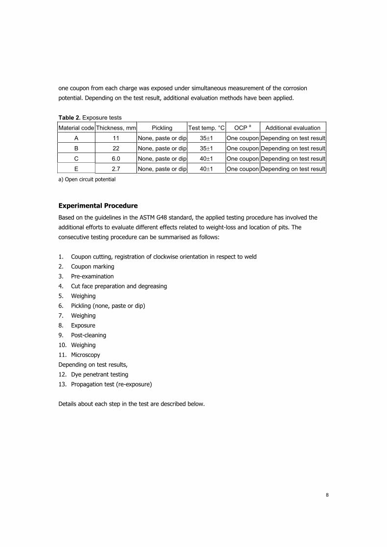
Table 2. Exposure tests
Material code Thickness, mm Pickling Test temp. °C OCP a Additional evaluation
A 11 None, paste or dip 35 1 One coupon Depending on test result
B 22 None, paste or dip 35 1 One coupon Depending on test result
C 6.0 None, paste or dip 40 1 One coupon Depending on test result
E 2.7 None, paste or dip 40 1 One coupon Depending on test result
a) Open circuit potential
Experimental Procedure
Based on the guidelines in the ASTM G48 standard, the applied testing procedure has involved the
additional efforts to evaluate different effects related to weight-loss and location of pits. The
consecutive testing procedure can be summarised as follows:
1. Coupon cutting, registration of clockwise orientation in respect to weld
2. Coupon marking
3. Pre-examination
4. Cut face preparation and degreasing
5. Weighing
6. Pickling (none, paste or dip)
7. Weighing
8. Exposure
9. Post-cleaning
10. Weighing
11. Microscopy
Depending on test results,
12. Dye penetrant testing
13. Propagation test (re-exposure)
Details about each step in the test are described below.

9
Coupon geometry and terminology
Wid
th
WW
Length
Thickness
Cap (test) face
B M
WM
FL
Root (test) face
Abbreviations
WM Weld metal
BM Base metal
FL Fusion line
WW Weld width
Side
End
CornerEdge
Figure 1. Coupon geometry
WW 30 mm: Width= 25 mm; Length= 50 mm WW > 30 mm: Width= 25 mm; Length= WW + 20mm
Clockwise position should be noted for each coupon. (start/stop point = 12 o’clock if rotated)
Coupon marking Engraver pen, root face in base metal. Make sure there is no interception with heat affected zone (HAZ).
Cut face preparation (ends and sides)
Wet polishing with 120 grit paper (ANSI, USA) or P120 paper (FEPA, EUROPE)
Pickling Options1. None 2. Paste pickling of cap face (not root face). Paste contains 5-7 wt% HF and 20 wt% HNO3 and is applied for 60 min at ambient temperature. 3. NORSOK-Dip, 5 wt% HF + 20 wt% HNO3, 60°C, 5 min
Examination before exposure Stereomicroscopy, x20. Record presence and position of major imperfections, e.g. pores or slags. Visually examine and describe the colour of heat tints on both faces.
Weighing precision Wt 120 g: 0.0001 g Wt > 120 g: 0.001 g
Test solution 100 g FeCl3 6H2O in 900 g H2O (standard)
Test solution volume 20 ml/cm2 coupon area

10
Coupon mounting Glass cradle (with or without electrical connection) as shown in Figure 2.
Titanium Gr.2 connector.
Coated by Teflon shrinking foil
Compression spring
Spring stop. Strip
Connector guide. Strip
Glass rod
ASTM G48 Holder Holder for OCP measurement
Figure 2. Glass holders for exposure with and without OCP measurement.
Exposure time 24 hours in pre-heated test solution
Exposure method Fixed temperature (according to specification).
Post-cleaning Ultrasonic, 5 min. in ethanol.
Microscopy after exposure Stereomicroscopy, x20. Locate pits using a needle.
Additional Evaluation
Dye penetrant test All coupons showing weight-loss > 1 g/m2
Procedure for Dye Penetrant Inspection. - Specimen is dipped in penetrant dye for 2 sec and left for 15 min to absorb dye. Water based Magnaflux SKL-WP is used as dye. - Excess dye is flushed away from the surface by showering the specimen softly with water. - The specimen is wiped with soft paper soaked with Magnaflux SKC-s Cleaner. - A thin layer of Magneflux SKD-52 Developer is sprayed on the specimen while it is rotated. Specimen is left for 15 min. - Location of developed pits, cracks etc. is registered.
Propagation test Coupons showing weight-loss > 1 g/ m2 but no obvious attack are retested for 24 hours. Before retesting, the coupon is ultrasonically cleaned in ethanol to remove any dye penetrant solution.
Metallographic examination Coupons showing an attack different from pitting. Microstructure along attack is characterised.

11
Results
The results of the exposure tests are presented in Table 3.
It is noticed that the welds with small wall thickness (groups D and E) pass the test with low weight-losses well below the 1.0 g/m2 criterion. Coupon preparation (i.e. pickling) does not affect the obtained weight-loss considerably. Consequently, there was no need for additional examination of these coupons, i.e. dye penetrant and metallographic examination
The results of the thick-walled welds (A and B) are more scattered.
Material A does not show pitting for any of the six tested coupons. However, in three cases the weight-loss exceeds 1.0 g/m2, which in some practices would fail the coupon. Pickling with pickling paste (partly removing surface oxides) does not affect the weight-loss considerably, whereas dip pickling (surface oxides removed) or propagation testing result in much lower weight-loss. On this basis, the high weight-loss observed for some of the coupons is ascribed to a pickling effect of surface oxides during exposure in the ferric chloride test solution.
Material B fails the test in all tests when using the 1.0 g/m2 weight-loss criterion. However, one of the coupons (B05) differs from the other by showing a moderate low weight-loss, possibly due to variations along the weld.
It should be noted that none of the tested coupons showed pitting on cut-edges despite that the prepared finish (120-grit) is coarser than some practices.
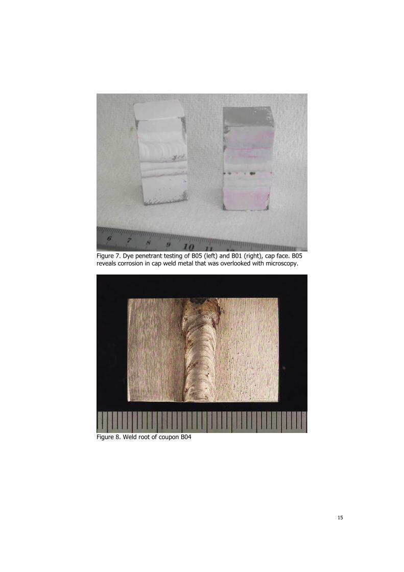
Additional pentrant examination was applied in eight cases (coupons A01, A03, A04, B01, B02, B03, B04, B06) when the weight-loss indicated corrosion. This technique proved gainful by revealing pits overlooked by microscopy in some cases. Figures 3 to 7 show examples of exposed coupons before and after dye penetrant testing.
Similarly, propagation testing was applied in four cases (coupons: A01, A03, A04, B05). This technique also proved gainful by identifying pickling effects in some cases.
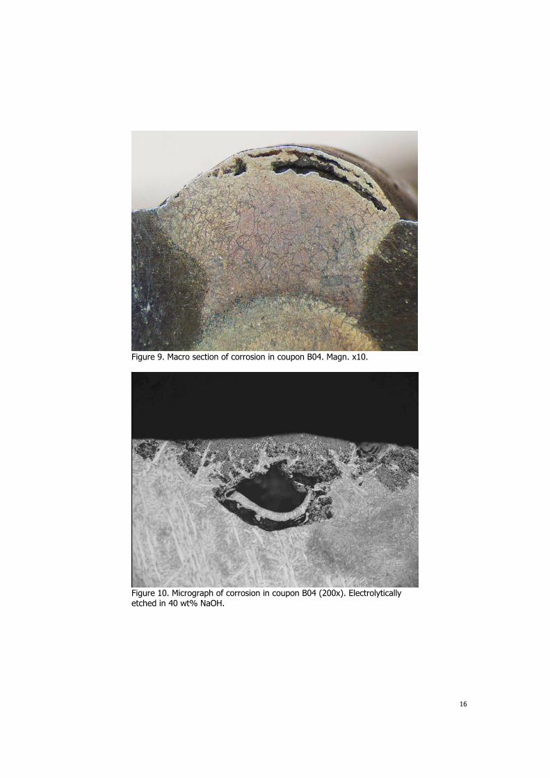
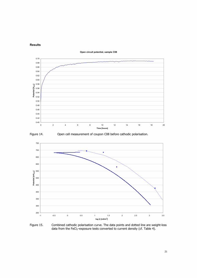
Metallographic examination was carried out on coupon B04 since this material show an attack different from pitting. Parts of the weld root suffered from severe corrosion attacks (Figure 8 and figure 9). The most severe corrosion was observed in an area of the weld root wider than the adjacent weld deposits, indicating locally higher heat input. This is most likely due to a stop/start of the welding giving a crater weld defect. The etched cross section (40 wt% NaOH-electrolytic) of the weld in figure 10 shows defects and inclusions related to the observed corrosion attacks. These defects are assumed to be the cause of the observed corrosion. No defects or inclusions were observed at etched cross section of unexposed coupon B08, Figure 11.
Moreover, it should be noted that the ferrite content of the B welds was within the acceptable range (30-70%). In the weld metal affected by corrosion the ferrite content was 38% (min. 32%, max. 50%).

12
Ta
ble
3. Resu
lt s
um
mary
of
exp
osu
re t
est
s.

13
Figure 3. Exposed coupons: A01, A03, A05.
Figure 4. Exposed coupons: B01, B03, B05.

14
Figure 5. Coupons A01 and A03 after dye penetrant testing. Indications on A01 are not due to corrosion.
Figure 6. Coupons B05 (left) and B01 (right) after dye penetrant testing, root face. B05 shows no indications, whereas B01 shows several pits in the weld metal.
15
Figure 7. Dye penetrant testing of B05 (left) and B01 (right), cap face. B05 reveals corrosion in cap weld metal that was overlooked with microscopy.
Figure 8. Weld root of coupon B04
16
Figure 9. Macro section of corrosion in coupon B04. Magn. x10.
Figure 10. Micrograph of corrosion in coupon B04 (200x). Electrolytically etched in 40 wt% NaOH.

17
Figure 11. Micrograph of unexposed coupon B08 (200x). Electrolytically etched in 40 wt% NaOH.

18
Electrochemical Tests – Series I
The aim of the electrochemical tests has been to evaluate to what extent pitting depolarises the
coupon during exposure. This question is relevant if pitting occurs on other surfaces than the test
face, since a strong depolarisation may protect the coupon against additional attack and thereby
compromise the test result.
Moreover, critical pitting temperature (CPT) measurements were carried out to evaluate the
correlation of results obtained in the acidic G48 test media and pH neutral media (1M NaCl).
OCP Measurement during Exposure in Ferric Chloride Solution
Experimental Procedure
The OCP measurements were performed for some of the coupons during exposure in the ferric
chloride test solution. Electrical connection was made using a spring-loaded titanium connector as
shown in Figure 2. The corrosion potential was measured with saturated calomel electrode at 5
minutes interval using a datalogger.
Results
Figure 12 and 13 show the results of the OCP measurements.
It appears from Figure 12 that the passive coupons (D01 and E01) obtain a very stable potential of
685 to 695 mV SCE within five hours of exposure. In comparison to this, the actively corroding coupon
(B01) shows an unsteady corrosion potential in the range of 400-500 mV SCE. Coupon A01 falls in
between, having a corrosion potential of approx. 600 mV SCE. This coupon showed no pitting but a
considerable weight-loss due to a pickling effect.
When propagation testing the two active coupons, a slightly different behaviour is observed, Figure
13. Coupon B01 still shows an active behaviour although more noble, whereas A01 exhibits a stable
passive behaviour at a potential of 690 mV SCE.
In summary, the observed potential behaviour correlates very well with the results obtained from
subsequent examination by microscopy and weight-loss determination.

19
0.2
0.3
0.4
0.5
0.6
0.7
0.8
0 5 10 15 20 25
Time (hr)
Po
ten
tia
l (V
vs S
CE
)
A01
B01
D01
E01
Figure 12. OCP development during exposure. A01 and B01 show signs of active corrosion (i.e. depolarisation) whereas D01 and E01 show a stable passive behaviour.
0.2
0.3
0.4
0.5
0.6
0.7
0.8
0 5 10 15 20 25
Time (hr)
Po
ten
tia
l (V
vs S
CE
)
A01-P
B05-P
Figure 13. OCP development during propagation testing of A01 and B05. B05 shows signs of active corrosion (i.e. depolarisation) whereas A01 shows a stable passive behaviour.

20
Cathodic Polarisation in Ferric Chloride Solution
Experimental Procedure
Four coupons were polarised cathodically to evaluate the cathode properties of stainless steel in ferric
chloride; coupon A02, A12, C08 and C spare.
The cathodic polarization measurements were performed in the ferric chloride test solution. Electrical
connection was made using a spring-loaded titanium connector as shown in Figure 2. The corrosion
potential was measured with saturated calomel electrode at 5 minutes interval using a datalogger. The
OCP stabilization period was approximately 18 hours.
Cathodic polarisation:
Polarization range: + 5 mV vs. OCP to +300 mV vs. saturated calomel electrode
Scan rate: 0.1 mV/ second
Logging interval: 20 seconds
Through re-calculation of the of the weight loss to an average current density during the 24 hour
exposure, the measured OCP’s (average values) can be plotted as a kind of polarisation curve.
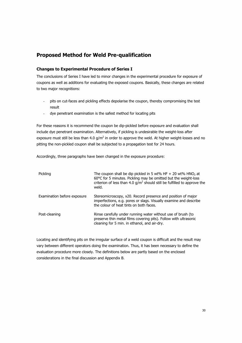
The OCP measurements for coupon C08 and the combined (4 specimens) cathodic polarization curve
are presented in Figures 14 and 15.
21
Results
Open circuit potential, sample C08
0.40
0.42
0.44
0.46
0.48
0.50
0.52
0.54
0.56
0.58
0.60
0.62
0.64
0.66
0.68
0.70
0 2 4 6 8 10 12 14 16 18 20
Time [hours]
Po
ten
tial
[VS
CE]
Figure 14. Open cell measurement of coupon C08 before cathodic polarisation.
250
300
350
400
450
500
550
600
650
700
750
-1 -0.5 0 0.5 1 1.5 2 2.5 3 3.5
log |i| [mA/m2]
Po
ten
tia
l [m
VS
CE]
Figure 15. Combined cathodic polarisation curve. The data points and dotted line are weight-loss data from the FeCl3–exposure tests converted to current density (cf. Table 4).

22
Table 4. Interpretation of cathodic polarisation.
Source Exposure test Cathodic polarisation
Corrosion rate Corrosion
potential Depolarisation
Corresponding
current density a
Expected de-
polarisation
g/m2 mV SCE mV mA/m2 mV
Coupon D01 0.11 695 0 5 50
Coupon E01 0.45 685 10 20 105
Coupon A01 1.4 580 115 64 164
Coupon B01 35 428 267 1600 415
a) Equivalent weight of super duplex: 24.6 g/mol.
The results of the cathodic polarisation show only limited agreement with those obtained from the
exposure test, as illustrated in Figure 15 and Table 4. The cathodic polarisation data generally give
larger depolarisation than observed in the exposure tests. For instance the fairly low corrosion rate of
1.4 g/m2 of Coupon A01 resulted in 120 mV depolarisation (Figure 10) which should be compared with
180 mV from the polarisation curve.
With a depolarsation of 100 mV, it appears that the corresponding corrosion rate is in the range of 20
to 60 mA/m2 (or 0.4 – 1.4 g/m2). On this basis, it can be expected that depolarisation will be within
100 mV as long as the overall weight-loss is less than 1.0 g/m2.

23
CPT Measurements
Experimental Procedure
The CPT tests were based on the procedure in the ASTM G150 standard9. Due to the complex coupon
geometry of the weld specimens, the technique had to be slightly modified. This applies to the coupon
mounting, which was done using the electrode holder in Figure 2. Moreover, the tests were run from
5°C (in stead of 0°C). Otherwise the test parameters were in agreement with ASTM G150, i.e.:
Test solution: 1M NaCl (3.5% Cl-), nitrogen purged
Hold potential: 700 mV SCE
Sweep rate: 1°C/min
These test conditions are comparable to that of G48 when it comes to potential and chloride
concentration. The major difference is the neutral pH of the G150 solution and low pH of the G48
solution.
The CPT was read at the point where current exceeds 0.1 A/cm2 and is followed by persistent rise in
current.
Results
Figures 16 to 22 show the obtained CPT curves while Table 5 summarises the results.
Table 5. Summary of CPT tests correlated with G48 results.
Material Coupon Pickled a CPT, °C b G150 corrosion morph. c G48 test result of material
A A09
A11
A07
No
No
Yes
32
28
61
No pits
No pits
Pits in root HAZ
Weight-loss < 1 g/m2 and
no pitting
B B07
B09
Yes
Yes
33
43
Large pit in root VM
Pits in root WM
Weight-loss > 1 g/m2 and
extensive pitting in root WM
D E04
E05
Yes
Yes
66 (58)d
62 (56)d
Pits in root HAZ
Pits in root HAZ
Weight-loss << 1 g/m2 and
no pitting
a) NORSOK dip: 20%HNO3, 5%HF, 60°C, 5 min. b) 0.1 mA/cm2 and persistent activation.
c) examined by dye penetrant. d) read before peak.
The first runs with non-pickled coupons of Material A gave a high passive current close to the current
criterion (i.e. 0.1 mA/cm2), and no distinct transition from passive condition to pitting. On this basis it
was decided to dip-pickle all coupons before testing. It appears that the pickling treatment had a
significant effect on material A by increasing CPT from 30°C to 61°C.

24
The thick-walled coupons of Material B show a high passive current, even in pickled condition.
Therefore, the reading of the CPT is questionable. Anyway, with CPT values from 33 to 43°C (or even
lower), this material shows the lowest pitting resistance.
The behaviour of Material D is more ideal by showing lower passive current and a fairly distinct
transition to pitting. These coupons show good reproducibility as to curve character and the read CPT
values.
The curves for Material D consistently show a current peak before final activation of the coupon. The
peaks are possibly related to dissolution of superficial intermetallic phases or chromium nitrides. From
the total charge of each peak (40 and 23 mC) the weight-loss due to these phases is estimated to
0.36 and 0.21 mg, equivalent to 0.12 g/m2 and 0.06 g/m2. Details are included as Appendix A.
Only limited development of pits is observed with the CPT test. Consequently, it is difficult or
impossible to locate pits by microscopy alone. For this reason all coupons were subjected to dye
penetrant examination. This enabled easy detection of pits.
The appropriateness of the current criterion used for reading CPT can be discussed. In several cases
high passive currents or current peaks were observed thereby confusing this reading. However, by
combining the current criterion with the persistent current rise criterion, a relative safe evaluation
method is obtained.
For comparison with the obtained values, Ames et al10,11 report CPT's between 50 and 60°C for
welded UNS 32750 material, whereas CPT of the base metal is 85°C. Customer acceptance criteria
were in one case >55°C and >80°C, respectively.
In summary, the CPT test provides a rapid and quantitative method for assessing the pitting
resistance of welds. Thus, this technique may possibly be used an alternative to G48-testing in doubt
cases. However, more work needs to be done to establish suitable acceptance criteria for this
technique.

25
Coupon No.: A09
0.0001
0.001
0.01
0.1
1
10
0 10 20 30 40 50 60 70 80 90 100
T (°C)
i (m
A/c
m²)
0
10
20
30
40
50
60
70
t (m
in)
i (mA/cm²)
t (min)
Figure 16. ASTM G150 CPT curve of Coupon A09 (not pickled). CPT is read at 32°C.
Coupon No.: A11
0.0001
0.001
0.01
0.1
1
10
0 10 20 30 40 50 60 70 80 90 100
T (°C)
i (m
A/c
m²)
0
10
20
30
40
50
60
70
t (m
in)
i (mA/cm²)
t (min)
Figure 17. ASTM G150 CPT curve of Coupon A11 (not pickled). CPT is read at 28°C.

26
Coupon No.: A07
0.0001
0.001
0.01
0.1
1
10
0 10 20 30 40 50 60 70 80 90 100
T (°C)
i (m
A/c
m²)
0
10
20
30
40
50
60
70
t (m
in)
i (mA/cm²)
t (min)
Figure 18. ASTM G150 CPT curve of Coupon A07 (dip-pickled). CPT is read at 61°C.
Coupon No.: B07
0.0001
0.001
0.01
0.1
1
10
0 10 20 30 40 50 60 70 80 90 100
T (°C)
i (m
A/c
m²)
0
10
20
30
40
50
60
70
t (m
in)
i (mA/cm²)
t (min)
Figure 19. ASTM G150 CPT curve of Coupon B07 (dip-pickled). CPT is read at 33°C.

27
Coupon No.: B09
0.0001
0.001
0.01
0.1
1
10
0 10 20 30 40 50 60 70 80 90 100
T (°C)
i (m
A/c
m²)
0
10
20
30
40
50
60
70
t (m
in)
i (mA/cm²)
t (min)
Figure 20. ASTM G150 CPT curve of Coupon B09 (dip-pickled). CPT is read at 43°C.
Coupon No.: E04
0.0001
0.001
0.01
0.1
1
10
0 10 20 30 40 50 60 70 80 90 100
T (°C)
i (m
A/c
m²)
0
10
20
30
40
50
60
70
t (m
in)
i (mA/cm²)
t (min)
Figure 21. ASTM G150 CPT curve of Coupon E04 (dip-pickled). CPT is read at 66°C (after the peak).

28
Coupon No.: E05
0.0001
0.001
0.01
0.1
1
10
0 10 20 30 40 50 60 70 80 90 100
T (°C)
i (m
A/c
m²)
0
10
20
30
40
50
60
70
t (m
in)
i (mA/cm²)
t (min)
Figure 22. ASTM G150 CPT curve of Coupon B09 (dip-pickled). CPT is read at 62°C (after the
peak).

29
Evaluation of Series I
The overall conclusions of Series I can be summarised as follows:
1. Corrosion with a weight-loss greater than approximately 1.0 g/m2 depolarises the coupon
more than 100 mV from the corrosion potential in passive state. This means that presence of
pits on other faces than the test face as well as pickling effects compromises the test result.
2. Residual oxides or heat tints result in pickling effects during exposure and depolarise the test
specimen. Consequently the test conditions become less aggressive, why the test result may
be too optimistic.
3. As a result of 1 and 2 the test specimen is recommended to be dip-pickled before exposure. If
dip-pickling is omitted there is an enhanced risk of exceeding the weight-loss criterion due to
pits on cut-faces or pickling effects.
4. Grinding of cut-faces to grit 120 seems to be sufficient. No cut-face pits were observed in the
tests, even for un-pickled coupons. Dip-pickling will further reduce the risk of cut-face pits.
Thus, we see no need to specify a finer cut-face finish than specified by ASTM G48, i.e.
grit 120.
5. Dye penetrant test should always be used to locate pits, regardless of weight-loss, since small
pits may be overlooked by microscopy at x20.
6. To determine CPT of weld coupons using the ASTM G150 test, dip-pickling is required to avoid
pickling effects during measurement and to obtain low passive currents. Otherwise, the test
seems to be a rapid test that provides good reproducibility and quantitative results as well as
useful information about intermetallic phases.
7. The ASTM G48 and ASTM G150 tests show fair correlation.
8. The propagation test is effective in distinguishing pickling effects from localised corrosion.
However, by introducing dip-pickling as standard preparation, this extension of the test
becomes necessary in fewer cases.
30
Proposed Method for Weld Pre-qualification
Changes to Experimental Procedure of Series I
The conclusions of Series I have led to minor changes in the experimental procedure for exposure of
coupons as well as additions for evaluating the exposed coupons. Basically, these changes are related
to two major recognitions:
- pits on cut-faces and pickling effects depolarise the coupon, thereby compromising the test
result
- dye penetrant examination is the safest method for locating pits
For these reasons it is recommend the coupon be dip-pickled before exposure and evaluation shall
include dye penetrant examination. Alternatively, if pickling is undesirable the weight-loss after
exposure must still be less than 4.0 g/m2 in order to approve the weld. At higher weight-losses and no
pitting the non-pickled coupon shall be subjected to a propagation test for 24 hours.
Accordingly, three paragraphs have been changed in the exposure procedure:
Pickling The coupon shall be dip pickled in 5 wt% HF + 20 wt% HNO3 at 60°C for 5 minutes. Pickling may be omitted but the weight-loss criterion of less than 4.0 g/m2 should still be fulfilled to approve the weld.
Examination before exposure Stereomicroscopy, x20. Record presence and position of major imperfections, e.g. pores or slags. Visually examine and describe the colour of heat tints on both faces.
Post-cleaning Rinse carefully under running water without use of brush (to preserve thin metal films covering pits). Follow with ultrasonic cleaning for 5 min. in ethanol, and air-dry.
Locating and identifying pits on the irregular surface of a weld coupon is difficult and the result may
vary between different operators doing the examination. Thus, it has been necessary to define the
evaluation procedure more closely. The definitions below are partly based on the enclosed
considerations in the final discussion and Appendix B.

31
Evaluation of Exposed Coupon
The exposed coupon shall be evaluated in accordance with the decision diagram (Figure 23) and as
explained below. This involves weight-loss determination, dye penetrant (DP) testing and microscopy.
Regardless of the coupon was dip-pickled or in the as-welded/as-delivered condition, 4.0 g/m2 shall be
used as the weight-loss criterion (WLcrit).
If the coupon shows no indications in the dye penetrant test and the weight-loss is below the weight-
loss criterion, the coupon passes the test.
If indications appear, the position and degree of each indication shall be recorded on a sketch of the
coupon. The degree is distinguished as 1) just visible, 2) moderate or 3) severe.
Subsequently, the coupon, still covered with penetrant developer, shall be examined under a
stereomicroscope at 20x magnification. Each indication shall be examined using a needle to carefully
remove the penetrant developer and to probe for subsurface attack. If subsurface attack is observed
the indication is characterised as a pit (or corrosion).
The location and size of pits are decisive for whether the coupon passes or fails the test according to
Table 6.
The presence of pits on faces apart from the test face may be ignored if the possibility of
depolarisation during exposure can be excluded. For this purpose it shall be verified by measurement
of depth and diameter that the total pit volume (Vpits) is less than Vmax, given by:
Area Wmax Area [cm2] Vmax [mm3] =
Dens =
78
where:
Area = coupon area
Wmax = weight-loss without depolarisation (1.0 g/m2)
Dens = steel density (7.8 g/cm3)
Other indications that look like pits (e.g. dissolved slags or small weld pores etc.) may be ignored if:
The presence of the imperfection was recorded before exposure, or
The indication appears as “just visible” in the dye penetrant test
Table 6. Criteria for evaluating of the exposed coupon.
Weight-loss (WL) Dye penetrant indications
4 g/m2 > 4 g/m2
None Pass Propagation test
Indications but no pits Pass Propagation test
Vpits Vmax Pass New test Pits on faces apart
from test face Vpits > Vmax New test
Pits on test face Fail

32
Acceptance Criteria:
Temperature, Tcrit
Test face
Coupon size
Weld width > 30 mm
25 x (WW+20) x WT
Weld width 30 mm
25 x 50 x WT
Pickling (optional)
20%HNO3, 5%HF, 60oC, 5 min
Exposure
6%FeCl3, 24 hours, Tcrit
Weight-loss
Dye penetrant
Propagation
testPass
No pits andWL 4 g/m²
Pits on other faces
Fail
Pits on test face
Propagation test
No pits butWL > 4 g/m²
Coupon
depolarised ?
Pass
No indicationsand WL 4 g/m² Indications
Test new
coupon
Microscopy, x20
No indicationsbut WL > 4 g/m²
Vpits>Vmaxand/or
WL > 4g/m²
Pass
Vpits Vmax and
WL 4 g/m²
Figure 23. Decision diagram for ASTM G48 pre-qualification testing of welds according to new Nordtest procedure. Test temperature and test face shall be decided before test. The weight-loss criterion (WLcrit) is 4.0 g/m2. The maximum volume of pits on faces apart from the test face (Vmax) is calculated from the coupon area, i.e. Vmax [mm3] = Area [cm2] / 78.
33
Exposure Tests - Series II
Objective
The objective of the second series of exposure tests has been to evaluate the new improved method
for weld pre-qualification. The tested materials were deliberately selected to include both high quality
welds and discarded welds to cover a wide range of weld qualities.
Experimental Plan
The experimental plan has involved exposure of two weld qualities of super duplex stainless steel
(UNS32750), i.e. a thin-walled and thick walled pipe material:
Material C: OD x WT: 56.2 x 2.7 mm Test temperature: 40 1°C
Material F: OD x WT: 300 x 34.8 mm Test temperature: 35 1°C
Coupons from each charge were exposed at DNV and FORCE according to the new procedure
described in the previous section.
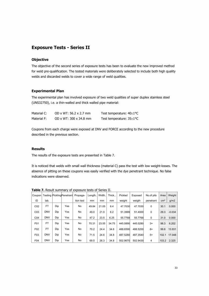
Results
The results of the exposure tests are presented in Table 7.
It is noticed that welds with small wall thickness (material C) pass the test with low weight-losses. The
absence of pitting on these coupons was easily verified with the dye penetrant technique. No false
indications were observed.
Table 7. Result summary of exposure tests of Series II.
Coupon
ID
Testing
lab.
PicklingPenetrant Propaga-
tion test
Length,
mm
Width,
mm
Thick.,
mm
Pickled
weight
Exposed
weigth
No.of pits
penetrant
Area
cm²
Weight
g/m2
C02 FT Dip Yes No 49.84 21.05 6.4 47.7030 47.7030 0 30.1 0.000
C03 DNV Dip Yes No 49.0 21.0 6.2 51.3999 51.4000 0 29.3 -0.034
C04 DNV Dip Yes No 47.2 23.5 6.25 55.7768 55.7768 0 31.0 0.000
F01 FT Dip Yes No 70.31 23.55 34.75 445.0890 445.0280 3+ 98.3 6.202
F02 FT Dip Yes No 70.2 24.4 34.6 488.6590 488.5200 8+ 99.8 13.931
F03 DNV Dip Yes No 71.5 24.6 34.8 487.5280 487.3540 5+ 102.1 17.048
F04 DNV Dip Yes No 69.5 26.3 34.8 502.9670 502.9430 4 103.2 2.325

34
The thick-walled welds (material F) show pitting in all cases and significant weight-loss. By using the
dye penetrant technique all pits were easily located.
Although none of the tested materials were in the doubtful range, the experience with the new
procedure from the second series of exposure tests was satisfactory.
Discussion
The proposed method offers major improvements as to location and identification of pits as well as
interpretation of results. Especially the application of dye penetrant examination proved to be gainful.
However, the test was not established without compromises.
For instance, it was chosen to leave dip-pickling of the coupon as an option, although this treatment
reduces the risk of cut-face pits and depolarisation during exposure. On the other hand this treatment
involves hazardous chemicals and may in fact be irrelevant for thin-walled welds, like materials C, D
and E in the above study. These materials showed low weight-loss regardless of pickling. To account
for doubtful cases arising from non-pickled coupons, clear criteria for retesting or propagation have
been defined for the proposed method.
The depolarisation effect has been emphasised throughout the study to evaluate both the significance
of cut-face pits and the possibility of undesirable potential-drop leading to too optimistic test results.
The maximum allowable depolarisation was defined as 100 mV, which corresponds to an average
corrosion rate of 1.0 g/m2 at exposure for 24 hours. To distinguish whether this level is exceeded
volumetric assessment (of pits) is specified rather than gravimetric measurement, since the precision
of weighing may be in same range of 1.0 g/m2, especially when testing large coupons. For the same
reason 4.0 g/m2 was chosen as the weight-loss criterion for rejecting welds. This criterion is already
common in most of the existing practices.
On this basis, we still see some possibilities for improving or simplifying the test method. For instance,
if the requirements for weighing were tightened, this would allow the use of a smaller and more
conservative weight-loss criterion. It may possibly be obtained by specifying a maximum coupon size
with an alternate geometry thereby enabling the use of more accurate balances. However, this
possibility was not studied further in the project. Similarly, other issues like coupon sampling and
heat-tint effects could be studied and defined better.
Although improvements may be added later, the proposed method still provides safer basis that
prevents questionable results to a greater extent than existing practices.

35
Conclusion
Based on a comparative evaluation of existing practices, an improved method is proposed for ASTM
G48 corrosion testing of welds. The improvements are mainly related to two major recognitions:
Pits on cut-faces and pickling effects depolarise the coupon and may thereby result in too
optimistic test results
Pits may be overlooked by microscopy
To account for this the proposed method includes two major additions in comparison to existing
practices:
Locating and identifying pits on the exposed coupon shall include dye penetrant examination
in combination with microscopy.
Pits on faces apart from the test face may be accepted if the possibility of depolarisation can
be excluded by volumetric assessments.
In addition, dip-pickling of the coupon prior exposure is recommended, but still optional.
In doubt cases, the method clearly specifies whether retesting of a new coupon or propagation testing
shall be undertaken. Moreover, this evaluation is supported by a decision diagram that clearly defines
whether the coupon passes or fails the test.
Although the established method may be further improved or simplified, it still provides a safer basis
for evaluating welds in comparison to existing practices.
The exposure tests were supplemented by electrochemical tests. By performing OCP measurements
and cathodic polarisation in the ferric chloride test solution, the effect of depolarisation was identified
and quantified. In addition, CPT of weld coupons was determined using the ASTM G150 test. This
technique proved rapid and quantitative for assessing the pitting resistance of welds, why it may be
used as an alternative to G48-testing in some cases.

36
References
1. ASTM G48-00, American Society for Testing and Materials (ASTM International), 2000.
2. Recommended practice for pitting corrosion testing of duplex stainless steel weldments by the
use of ferric chloride solution, TWI, publ. no. 5632/19/93, 1993.
3. Zitter H, Mori G, Hochörtler, Wieser H, Evaluation of CPT values determined by ASTM G48
practice, Materials and Corrosion, 53, 37-43, 2002.
4. Olsson C O A, Arnvig PE, Evaluation of HCl and Na-EDTA Additions for Ferric Chloride Testing
Using Auger Electron Spectroscopy, AvestaPolarit, ACOM, No.3:3, 1996
5. Lefebvre J, Potty, A, Experience with CPT Determination by means of ASTM G48 A - Attempt to
improve it, Soudo Metal, Publ. no. IX-H-264/92, 1992.
6. ASTM A923-01, American Society for Testing and Materials (ASTM International), 2001.
7. Welding and inspection of piping, NORSOK Standard, M-601, Rev.2, 1997
8. Technical Standard TS-12, Rev. 2, Mærsk Oil and Gas, 23.02.01, 2001
9. ASTM G150-99, American Society for Testing and Materials (ASTM International), 1999.
10. Ames N, Ramberg M, Johnson M, Johns T, Comparison of austenitic, super austenitic and super
duplex weld properties produced using GTAW flux, Stainless Steel World, 2001.
11. Ames N, Holmquist M, Johnson MQ, Orbital welding of small-bore super duplex tube using
GTAW flux, Proceedings of Duplex 2000, 2000.

37
Appendices
A. Charge calculations on CPT curves.
B. Dye penetrant examination and size considerations to define a suitable pit criterion
C. Proposed Nordtest Method

38
Appendix A. Charge Calculations
Coupon No.: E04
0
0.02
0.04
0.06
0.08
0.1
0.12
0.14
0.16
0.18
0.2
50 52 54 56 58 60 62 64 66 68 70
T (°C)
i (m
A/c
m²)
0
10
20
30
40
50
60
70
t (m
in)
i (mA/cm²)
t (min)
Peak: 39.7 mC/cm2 Area: 31 cm2 Weight-loss: 0.36 mg (coupon) or 0.12 g/m2
Coupon No.: E05
0
0.02
0.04
0.06
0.08
0.1
0.12
0.14
0.16
0.18
0.2
50 52 54 56 58 60 62 64 66 68 70
T (°C)
i (m
A/c
m²)
0
10
20
30
40
50
60
70
t (m
in)
i (mA/cm²)
t (min)
Peak: 22.6 mC/cm2 Area: 31 cm2 Weight-loss: 0.21 mg (coupon) or 0.06 g/m2

39
Appendix B. Dye penetrant examination and size considerations to define a
suitable pit criterion
Penetrant examinationIn order to evaluate the detection limit of the penetrant test, a flat specimen with pits were examined as a model material. The pits had been developed using the ASTM G150 CPT test. Due to precipitation of corrosion products, all pits could be identified from the smoke trails emerging from the pits, Figure B1.
The evaluation included following:
- Identification of pits, Figure B1
- Penetrant testing, Figure B2
- Identification of overlooked pits
- Size determination of overlooked pits, Figures B3 – B6
Summary The evaluation indicates that a pit size of 120 –150 µm in diameter and 20 µm in depth is on the borderline for detection with the penetrant test. This corresponds to a pit volume of 0.0002 to 0.0004 mm3 or a weight-loss of 0.0006 to 0.0012 g/m2/d (coupon area 25cm2).
In conclusion, penetrant examination will enable location of pits not detectable by weighing.
Size considerationsAn acceptable pit size, that does not compromise the test result, may be defined from a maximum allowable depolarisation of the coupon. An appropriate level for this is 100 mV based on the results of the OCP measurement during exposure. This means that we do not expect any significant change in the test conditions as long as the potential is in the range of 590 – 690 mV SCE
From the OCP measurements during exposure, depolarisation of more than 100 mV is not expected with an average corrosion rate of 1.0 g/m2 over 24 hours.
Using this criterion, it can be calculated that a single pit in the range of 0.03 to 0.08 mm3 (dependent on coupon area) will cause no significant depolarisation. A pit of this size is easily located with dye penetrant examination.
Coupon
Area
Max. pit volume
at 1.0 g/m2
Example pit size, as cube
Side length
cm2 mm
3 mm
25 0.321 0.68
30 0.385 0.73
40 0.513 0.80
60 0.769 0.92

40
Figure B1. Pits on flat specimen after ASTM G150 testing. Diameter of tested circle is 36 mm. The spike of the smoke trails indicates the location of pits. The four numbered pits were measured.
Figure B2. Location of pits after development of penetrant. Pits no. 1 and 2 were overlooked with penetrant.
1
2
4
3

41
Figure B3. Magn.x370 Pit 1 showing no indication in dye penetrant test. The pit measures 150 µm in diameter and 20 µm in depth.
Figure B4. Magn.x370 Pit 2 showing no indication in dye penetrant test. The pit measures 120 µm in diameter and 20 µm in depth.

42
Figure B5. Magn.x370 Pit 3 showing weak indication in dye penetrant test. The pit measures 160 µm in diameter and 20 µm in depth.
Figure B6. Magn.x180 Pit 4 showing distinct indication in dye penetrant test. The metal film covering the pit is left intact, i.e. it has not been probed with a needle. The pit measures 280 µm in diameter.

43
Figure B7. Magn.x180 Pit 4 after ultrasonic cleaning in ethanol for 5 minutes. The metal film covering the pit is still intact.
44
Appendix C. Proposed Nordtest Method

METHOD FOR PITTING CORROSION TESTING OF STAINLESS STEEL BASE
MATERIALS AND WELDS AND RELATED ALLOYS
BASED ON ASTM G48-A.
NORDTEST PROJECT NO. 1639-03
1. SCOPE
This method covers recommendations and practices for corrosion testing of stainless steel
welds based on the ASTM G48-A Method A (Ferric Chloride Pitting Test). In addition to the
ASTM standard, the current method describes practices for sample preparation, evaluation
and interpretation specifically adapted for corrosion testing of welds to ensure a high degree
of consistency in the test results.
The method is intended for pre-qualification of stainless steel welds in situations where welds
should fulfil certain acceptance criteria as defined by e.g. a contractor. These criteria include
test face and test temperature as well as requirements for sampling.
The weld coupon is prepared by cutting, wet polishing of cut faces and pickling (optional)
before it is exposed in the ferric chloride solution for 24 hours at the agreed test temperature.
Subsequently, the exposed coupon is evaluated by use of weight-loss determination, penetrant
examination and microscopy to locate pits. The coupon either passes or fails the test
dependent on the presence of pits. In doubt cases, the same coupon may be subjected to a
propagation test or re-testing of a new coupon.
2. FIELD OF APPLICATION
The method determines whether a weld resists exposure to ferric chloride solution at a
specified temperature without developing pitting or other localised forms of corrosion caused
by chloride containing media. The weld is characterised by a specific combination of material,
geometry and welding procedure.
The described method will show detrimental effects related to improper metallurgy or weld
geometry (pores) that may affect resistance against chloride induced corrosion, like pitting.
The test result mainly reflects material performance under submerged conditions in chloride
containing media under oxidising conditions (e.g. chlorinated seawater), whereas correlation
to other media is questionable.
The method is not valid for testing effects of heat tinting.
The described method is based on results of testing super duplex stainless steel welds, but the
same practice may be applied to welds and base materials of other CrNi / CrNiMo stainless
grades in addition to nickel based alloys and welds.
3. REFERENCES
3.1 ASTM G48 - 00, American Society for Testing and Materials, 2000.
3.2 Improved Method for ASTM G48 Corrosion Testing of Welds. Nordtest Project No.
1639-03, Technical report, December 2003.

4. DEFINITIONS
4.1 Terminology and abbreviations
NDE Non destructive examination
DPI Dye penetrant inspection
Heat tint Discoloration due to oxidation of metal surface
WPS Welding procedure specification
WL Weight-loss in g/m2
steel Steel density (7.8 g/cm3)
Vpits Total calculated volume of pits
Vmax Total volume of pits without depolarisation
Wid
th
WW
Length
Thickness
Cap (test) face
B M
WM
FL
Root (test) face
Abbreviations
WM Weld metal
BM Base metal
FL Fusion line
WW Weld width
Side
End
CornerEdge
Figure 1: Definitions related to coupon.
5. SAMPLING, SAMPLE HANDLING AND PREPARATION
The contractor shall specify the procedure for sampling and required amount of coupons.
6. TEST METHOD
The test method is based on the ASTM G48 Method A.
6.1 Principle
The test method is based on exposure of prepared coupons, pickling (optional), weight loss
determination, dye penetrant inspection and microscopy.
6.2 Equipment
Besides from the equipment specified in ASTM G48, the following equipment is required for
the test:
6.2.1 CuttingMetal saw or an abrasive disc with cooling liquid.
6.2.2 Polishing Equipment for wet grinding/polishing of metallographic specimens.
6.2.3 Coupon measuring
A calibrated calliper, resolution: 0.1 mm.
6.2.4 Weighing
A calibrated laboratory scale, resolution:Wt 120 g: 0.0001 g or
Wt > 120 g: 0.001 g.
6.2.5 Cleaning An appropriate ultrasonic cleaning bath.
6.2.6 ExaminationAn appropriate light microscope shall be used. Stereo microscope is recommended.
For pit depth measurements a microscope with calibrated fine focus knob shall be
used.
6.3 Testing environment
6.3.1 Environmental conditions
The test shall be performed under ordinary laboratory conditions concerning room
temperature and humidity.
6.3.2 Solutions
All solutions shall be prepared from demineralised water.
The pickling solution, 5 wt% HF + 20 wt% HNO3, shall be prepared from technical
grade reagents or better, i.e.
11 ml HF (40%, spec. gravity 1.13 g/ml)
22 ml HNO3 (65%, spec. gravity 1.41 g/ml)
57 ml H2O
The test solution, 6% FeCl3, shall be prepared within 24 hours from start of exposure
using analytical reagents, e.g.: 100 g FeCl3 * 6 H2O in 900 g H2O
6.3.3 Special safety measures: When handling HF, HNO3 and FeCl3 appropriate eye protection, safety gloves and
safety clothes shall be used when exposure risk is present. The work shall be carried
out in a ventilated cabinet. Reference is made to safety data sheet for further details.
6.4 Preparation of test coupons
6.4.1 Test coupons shall be prepared according to the diagram in Annex A and to the
following dimensions:
WW 30 mm: Width = 25 mm; Length = 50 mm
WW > 30 mm: Width = 25 mm; Length = WW + 20 mm
6.4.2 All cut faces of the coupon shall be wet-polished to a uniform finish using 120 grit
paper (ANSI, USA) or P120 paper (FEPA, EUROPE). Sharp edges of the coupon
shall be rounded.
6.4.3 If pickling is applied the coupon shall be dip-pickled for 5 minutes at 60°C in 5 wt%
HF + 20 wt% HNO3.
6.5 Test procedure and coupon evaluation
The procedure and evaluation of the exposed coupon shall be in accordance with the diagram
in Annex A and as described below.
6.5.1 The clockwise position, from which the coupon is sampled, should be recorded
(start/stop point = 12 o’clock if rotated)
6.5.2 Coupon preparation shall be according to section 6.4.
6.5.3 The coupon shall be cleaned with hot water using a hard brush. Then ultrasonically
degreased in ethanol for 5 minutes and dried.
6.5.4 The presence of major imperfections e.g. pores or slag inclusions shall be recorded
using microscope (20 x magnification).

6.5.5 The dimensions of the coupon shall be measured by a calibrated slide calliper. For
curved coupons the circumference shall be used.
6.5.6 Prior to exposure the test coupon shall be weight using a calibrated weight.
6.5.7 Test solution volume (6 wt% FeCl3) shall be at least 20 ml / cm2 in respect to the total
coupon area. Several coupons may be exposed simultaneously in the same container.
6.5.8 The test coupon shall be rinsed in fresh water subsequent to exposure. Brushing or
other mechanical treatment shall be avoided.
6.5.9 The coupon shall be ultrasonically degreased in ethanol for 5 minutes and dried.
6.5.10 Subsequent to cleaning, the weight loss shall be determined by using the same
calibrated weight as prior to exposure.
6.5.11 Penetrant examination shall be performed as Dye Penetrate Inspection. The inspection
shall be carried out by a trained NDE-operator for the applicable NDE method and in
accordance with an approved NDE procedure. E.g.: Specimen is dipped in penetrant
dye for 2 seconds and left for 15 minutes to absorb dye. Excess dye is flushed away
from the surface by showering the specimen softly with water. The specimen is wiped
with soft paper soaked with cleaner. A thin layer of developer is sprayed on the
specimen while it is rotated. Specimen is left with developer for 15 minutes.
6.5.12 Location of developed indications from DPI is registered and classified as: just visible,
moderate or severe.
6.5.13 The coupons, still covered with penetrant developer, shall be examined in a
microscope at 20 x magnification if indications or irregularities are detected by
penetrant examination.
6.5.14 Each indication shall be examined using a needle to carefully remove the penetrant
developer and to probe for subsurface attack. If subsurface attack is observed the
indication is characterised as a pit (or corrosion).
6.5.15 If propagation test is required, the coupon shall be ultrasonically degreased in ethanol
for 5 minutes and dried, before retesting.
6.6 Data processing
Depending on the microscopic examination one of the following four test results is obtained
in accordance with Table 6.1
6.6.1 Acceptable test
If the coupon shows no indications in the dye penetrant test and the weight-loss is below the
weight-loss criterion, the coupon passes the test.
If the coupon shows indications in the dye penetrant test and no pits are detected, the coupon
passes the test if the weight-loss is below the weight-loss criterion.
If measurement of depth and diameter of pits present on faces apart from the test face is
verified to have a total pit volume (Vpits) less than Vmax, and the weight loss is below the
weight loss criterion, the coupon passes the test. Vmax is given by:
A Wmax A [cm2] Vmax [mm3] =
steel
= 78
If indications that look like pits (e.g. dissolved slags or small weld pores etc.) was recorded
before exposure or the indication appears as “just visible” in the dye penetrant test, the
coupon passes the test, if the weight-loss is below the weight-loss criterion.

6.5.3 Rejection
If pits are recorded on the test face, the coupon fails the test.
6.5.4 Retesting
If pits present on faces apart from the test face are verified to have a total pit volume (Vpits) of
more than Vmax, a new coupon shall be tested.
6.5.5 Propagation testing
If the coupon shows no pits and the weight-loss is above the weight-loss criterion, the coupon
shall be propagation tested for additionally 24 hours at same test temperature.
Table 6.1 Criteria for evaluating of the exposed coupon.
Weight-loss (WL) Dye penetrant indications
4.0 g/m2 > 4.0 g/m
2
None Pass Propagation test
Indications but no pits Pass Propagation test
Vpits Vmax Pass New test Pits on faces apart
from test face Vpits > Vmax New test
Pits on test face Fail
6.7 Applicability
The described method is based on results of testing super duplex stainless steel welds, but the
same practice may be applied to welds and base materials of other CrNi / CrNiMo stainless
grades in addition to nickel based alloys and welds.
The described method has been validated by testing different welds of super duplex stainless
steels. Several coupons were exposed from each weld showing good repeatability as to the
determined weight-loss and character of corrosion. Details are described in /3.2/.
6.8 Uncertainty
The major source for spread in results would normally be related to variations along a weld,
e.g. presence of slag inclusions or pores. A coupon may fail the test due to such defects, but
this does not necessarily reflect general performance of the weld. Thus, retesting of two new
coupons from the same weld is recommended in such cases to evaluate whether the defects
are unusual or general.
The uncertainty of the method is also related to the weight measurements depending on
coupon size and the applied balance.

6.9 Test report
The test report shall be completed with data and units as shown in the example in Annex B.
The following items, including precision with which the results should be given, shall be
stated:
Test laboratory
Test face
Test temperature
Coupon ID
WPS number
Material grade
Surface preparation
Coupon dimensions (± 0.1 mm)
Surface area (± 0.1 cm2)
Coupon weight (± 0.0001 g when Wt < 150 g and ± 0.001g when Wt > 150 g)
Weight-loss (± 0.1 g/m2)
Temperature (± 1°C)
Number and location of pits
Test result, i.e. pass, fail, retest or propagation test.
7. ANNEXES
Annex A Decision diagram
Annex B Test report

Annex A
Decision diagram

Acceptance Criteria:
Temperature, Tcrit
Test face
Coupon size
Weld width > 30 mm
25 x (WW+20) x WT
Weld width 30 mm
25 x 50 x WT
Pickling (optional)
20%HNO3, 5%HF, 60oC, 5 min
Exposure
6%FeCl3, 24 hours, Tcrit
Weight-loss
Dye penetrant
Propagation
testPass
No pits andWL 4 g/m²
Pits on other faces
Fail
Pits on test face
Propagation test
No pits butWL > 4 g/m²
Coupon
depolarised ?
Pass
No indicationsand WL 4 g/m² Indications
Test new
coupon
Microscopy, x20
No indicationsbut WL > 4 g/m²
Vpits>Vmaxand/or
WL > 4g/m²
Pass
Vpits Vmax and
WL 4 g/m²
Figure A1. Decision diagram for ASTM G48 pre-qualification testing of welds.

Annex B
Test report
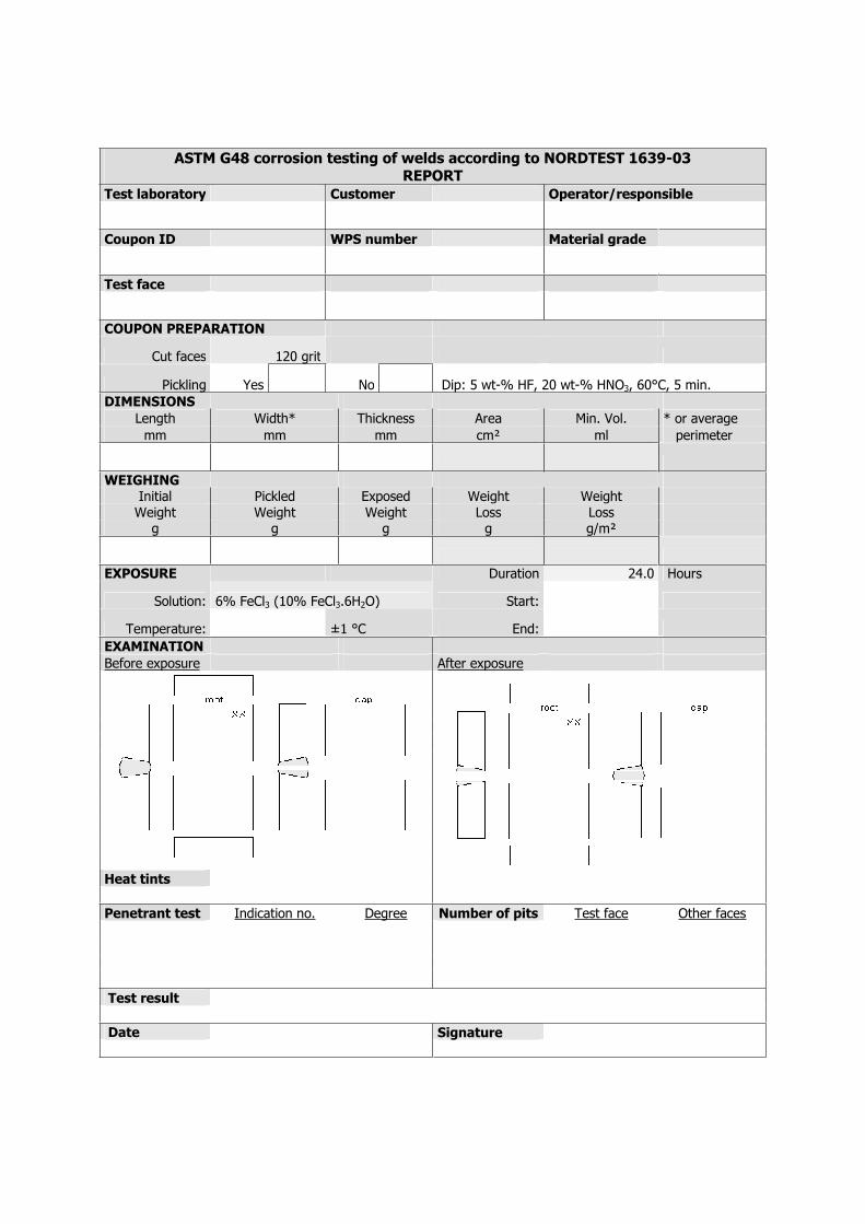
ASTM G48 corrosion testing of welds according to NORDTEST 1639-03 REPORT
Test laboratory Customer Operator/responsible
Coupon ID WPS number Material grade
Test face
COUPON PREPARATION
Cut faces 120 grit
Pickling Yes No Dip: 5 wt-% HF, 20 wt-% HNO3, 60°C, 5 min. DIMENSIONS
Length Width* Thickness Area Min. Vol. * or average mm mm mm cm² ml perimeter
WEIGHING
Initial Pickled Exposed Weight Weight Weight Weight Weight Loss Loss
g g g g g/m²
EXPOSURE Duration 24.0 Hours
Solution: 6% FeCl3 (10% FeCl3.6H2O) Start:
Temperature: ±1 °C End:
EXAMINATION
Before exposure After exposure
Heat tints
Penetrant test Indication no. Degree Number of pits Test face Other faces
Test result
Date Signature