Embed Size (px)
Citation preview

International Journal for Service Learning in Engineering,
Humanitarian Engineering and Social Entrepreneurship
Vol. 11, No. 1, pp. 32-50, Spring 2016
ISSN 1555-9033
32
Improved Field Methods for Construction of Concrete
Biosand Water Filter Housings
Timothy J. Bowser, P.E. Department of Biosystems & Ag Engineering
Oklahoma State University
Paul R. Weckler, P.E. Department of Biosystems & Ag Engineering
Oklahoma State University
Marquette Bugg Masters of International Ag Program
Oklahoma State University
Eric Lam Consulting Engineer
CIMMYT
Texcoco, CP 56237 Mexico
Jim F. Chamberlain, P.E., BCEE Water Technologies for Emerging Regions (WaTER) Center
University of Oklahoma
Abstract – This paper discusses two alternative solutions to remedy the difficulties and
challenges associated with low-cost field methods for construction of concrete biosand
water filter housings. Outer and inner forms are required to retain the concrete in the
desired shape for the filter housing. Removal of the inner form can be a challenging
process. The first method outlines a procedure for the use of an inflatable boat fender that
is used for the inner form. The boat fender can be deflated and easily removed after the
concrete is set. The second method uses stuffed feed sacks for the inner form. The feed
sacks are stuffed with a granular material and stacked vertically. After the concrete is set,
the granular material is removed and the feed sacks are readily separated from the
concrete. Both methods of construction are described in detail. Findings include two rapid
field methods for constructing inexpensive concrete biosand water filter housings.
Index Terms - Biosand, water, filter, concrete, housing, household, field, method
INTRODUCTION
A Biosand Filter (BSF) is a home-use, slow-sand water filter that was developed by Dr. David
Manz of the University of Calgary, Canada.1 Concrete is the material of choice for BSF housings
in many parts of the world because of its durability and low cost. The Centre for Affordable
Water and Sanitation Technology2 (CAWST) has led efforts in the design and application of the
concrete BSF housing, along with a similar model designed by BushProof.3 The concrete BSF
can be entirely poured on-site, with a reusable mold, simple tools and few supplies, making it
very effective at meeting sustained water needs for communities in developing countries.4
The CAWST and BushProof models can be mass-produced using steel molds for the
concrete casting. The steel molds are relatively expensive and not practical to build on-site for
casting of smaller numbers of filter housings. As an alternative, Lam4 encouraged the use of

International Journal for Service Learning in Engineering,
Humanitarian Engineering and Social Entrepreneurship
Vol. 11, No. 1, pp. 32-50, Spring 2016
ISSN 1555-9033
33
native wood materials to build forms. Lam suggested plywood or dimensional timbers, held
together with screws or nails. Lam acknowledged that the wooden forms were not as durable as
the steel versions, but were low-cost and more feasible for small-scale production centers located
in remote areas.
An example of a cast concrete BSF and the wooden forms used to make it is shown in Fig. 1.
Regardless of the existing design of the form, or the type of materials used to build the form, one
of the most difficult steps in the fabrication process has been the removal of the internal form (an
internal form is shown in Fig. 2). There are several reasons for this difficulty: 1. Adhesion
and/or cohesion of the concrete to the surface of the form; 2. Incorrect geometry of the form
(manufacturing error) that causes binding between the form and concrete; 3. Swelling of porous
forms (e.g. wood); 4. Damage to the form that caused it to be misshapen (often happens with
repeated use); 4. Rust, dirt, or foreign material on the form; and, 5. Improper use of the form
(e.g. placement and anchoring).
FIGURE 1 EXAMPLE OF A COMPLETED CAST CONCRETE BSF (LEFT) AND WOODEN FORMS USED IN THE FABRICATION
PROCESS (RIGHT)

International Journal for Service Learning in Engineering,
Humanitarian Engineering and Social Entrepreneurship
Vol. 11, No. 1, pp. 32-50, Spring 2016
ISSN 1555-9033
34
FIGURE 2 INNER FORM FOR CONCRETE BSF HOUSING WITH TAPER AND PLASTIC COVERING TO IMPROVE RELEASE
FROM CONCRETE
Evidence of the difficulty of removing the inner form can be found in the literature. The
BushProof instructions describe coating the inner form surfaces with food grease3 to help
promote release of the concrete. This procedure alone suggests that the form may be difficult to
remove. Beyond the grease coating, a mechanical “puller”, fabricated of steel, was required5 to
remove the BushProof inner form. The BushProof puller resembled a gear remover commonly
used in power transmission applications. The puller was anchored to the outside mold and
attached to the inner mold. A threaded rod was turned with a wrench to pull up on the inner
mold. The CAWST instructions for using the biosand filter mold described a device that was
similar to the BushProof puller that they called an “extractor”.2 Tapping the mold with a hammer
or piece of wood was also encouraged to help release the concrete from the form.1, 2
The authors have extensive experience using wooden forms to make concrete biosand filter
housings in local workshops held in Oklahoma and on site in Honduras, Guatemala and
Tanzania. Local workshops include the annual, International WaTER conference held at the
University of Oklahoma, Norman and led by author Chamberlain. This workshop focuses on
water needs in developing countries. The Oklahoma State University chapter of Engineers
without Borders has ongoing humanitarian aid projects involving BSF manufacturing and
application in Honduras and Guatemala. Authors Weckler and Lam have served as the club
advisor and president, respectively. Author Bowser has led a regional workshop in Tanzania in
cooperation with Pioneer Missions, Eads, Tennessee, to teach BSF construction to community
leaders from Kenya, Rwanda, Tanzania, and Uganda.

International Journal for Service Learning in Engineering,
Humanitarian Engineering and Social Entrepreneurship
Vol. 11, No. 1, pp. 32-50, Spring 2016
ISSN 1555-9033
35
On many occasions, the authors have witnessed the inner form binding for each of the
reasons listed above. Frequently, the inner form can be removed with patience and hard work;
however, the form may be destroyed in the process. On occasion, the concrete biosand filter
housing is damaged or broken beyond repair during the process of removing the inner form.
Improvements have been suggested to help achieve release of the inner form with mixed
success. Lubrication using oils and fats are among the most common suggestions. Lubrication
often achieves a better release, but there are concerns about the unassessed effects of the residual
oil on the biosand filter layer and water quality. Lam4 taught the use of plastic wrap as an
alternative release agent. He wrapped plastic sheeting around the inner mold prior to setting it in
place (Fig. 2). The sheeting did not adhere to the concrete and prevented the wood from
absorbing moisture and swelling.
Another suggestion4 to help achieve better inner form release was to taper the form (see Figs.
2 and 3). In theory, tapering from the top (open end of the biosand water filter) to a reduced
profile at the bottom would eliminate the chances of the inner form wedging inside the concrete
structure. The slight taper would have little effect on the capacity and function of the water filter.
Field experience taught that the taper was difficult to achieve with available hand tools (hand or
power saw and crooked or warped wood of varying thickness). If even slightly misshapen, the
tapered inner mold may solidly wedge in the concrete.
FIGURE 3 DRAWING OF INNER FORM FOR CONCRETE BSF HOUSING WITH TAPER AND SEPARATE PIECES FOR
INDIVIDUAL REMOVAL.4
Finally, Lam4 suggested making the inner form in separate pieces that could be removed
individually (see Fig. 3). A cleat and spacer were used to hold the lower portion of the form in
place during the concrete pouring and curing steps. The upper portion of the inner form (nearest
the opening of the biosand water filter housing) was held in place using temporary blocks.
Pressure from the concrete forced the pieces of the form together and could cause them to move
out of position or twist. Pressure from the concrete and small movements of the inner form
during pouring and curing has also caused problems with form removal.
This paper outlines two new methods for constructing concrete biosand water filter housings
that eliminate the problems associated with inner form removal. Both methods use materials that
are relatively inexpensive, convenient for travel, and readily available. The methods presented
International Journal for Service Learning in Engineering,
Humanitarian Engineering and Social Entrepreneurship
Vol. 11, No. 1, pp. 32-50, Spring 2016
ISSN 1555-9033
36
are general guidelines and not meant to be rigid instructions. The engaged reader will find many
ways to improve and modify the methods to achieve optimum results for their location and end
use requirements.
METHODS
The first novel method for constructing concrete BSF housings requires the use of an
inflatable inner form. The outer form can be fabricated of most any material that will hold the
concrete in place. The inflatable inner form can be deflated after the concrete sets and then
removed without difficulty. This is a vast improvement over the previously described, rigid inner
forms made of wood or metal. Basic requirements for the inflatable form include: rugged;
inflatable with a hand pump; inflation valve located on the distal end; means of anchoring the
inflatable in the form; low cost; and, availability. A search of the literature revealed numerous
inflatable cylinders that were available for use in applications such as vehicle suspension,
aviation, marine, and recreation.
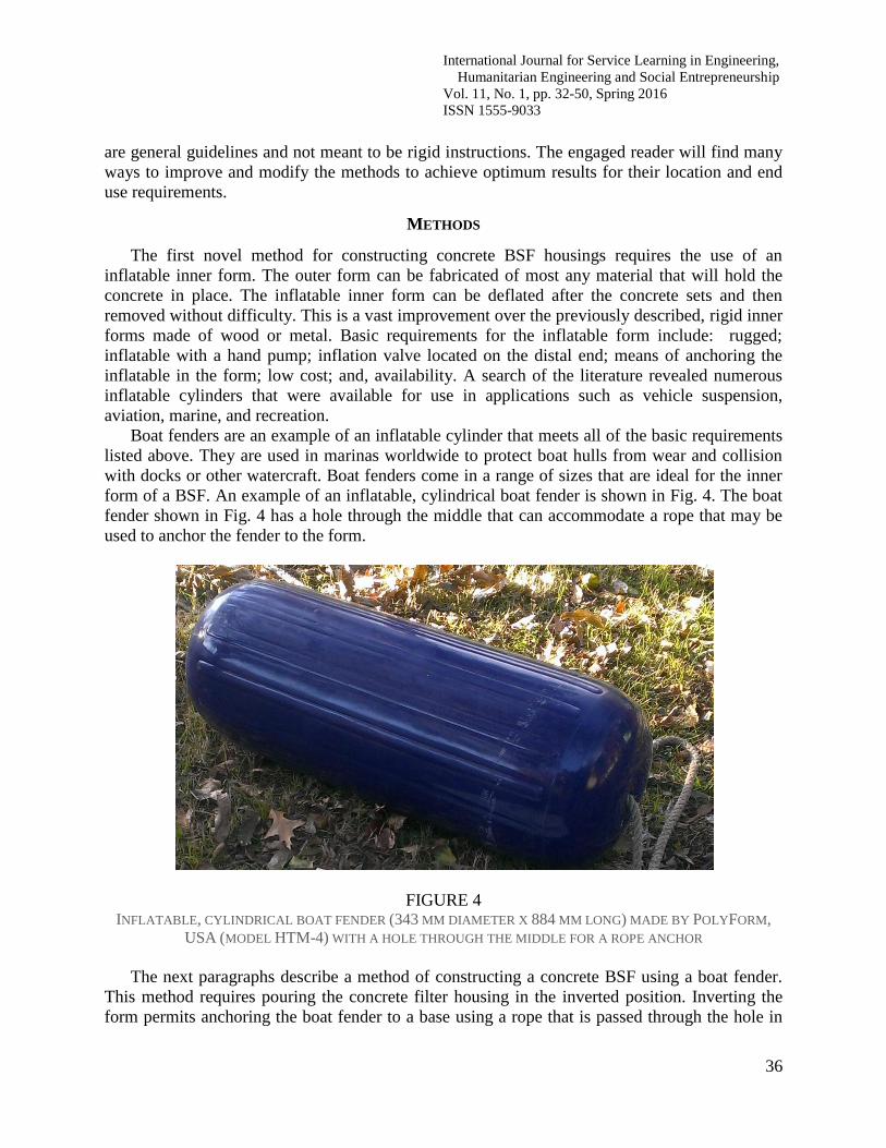
Boat fenders are an example of an inflatable cylinder that meets all of the basic requirements
listed above. They are used in marinas worldwide to protect boat hulls from wear and collision
with docks or other watercraft. Boat fenders come in a range of sizes that are ideal for the inner
form of a BSF. An example of an inflatable, cylindrical boat fender is shown in Fig. 4. The boat
fender shown in Fig. 4 has a hole through the middle that can accommodate a rope that may be
used to anchor the fender to the form.
FIGURE 4 INFLATABLE, CYLINDRICAL BOAT FENDER (343 MM DIAMETER X 884 MM LONG) MADE BY POLYFORM,
USA (MODEL HTM-4) WITH A HOLE THROUGH THE MIDDLE FOR A ROPE ANCHOR
The next paragraphs describe a method of constructing a concrete BSF using a boat fender.
This method requires pouring the concrete filter housing in the inverted position. Inverting the
form permits anchoring the boat fender to a base using a rope that is passed through the hole in

International Journal for Service Learning in Engineering,
Humanitarian Engineering and Social Entrepreneurship
Vol. 11, No. 1, pp. 32-50, Spring 2016
ISSN 1555-9033
37
the middle of the boat fender. Better control of the drain tube placement for the BSF is one
advantage of having the form in the inverted position. A list of required materials and tools is
given in Table 1.
TABLE 1 LIST OF REQUIRED MATERIALS AND TOOLS NEEDED TO POUR A CONCRETE BIOSAND WATER FILTER
HOUSING USING AN INFLATABLE INNER FORM
Materials Hand tools
1. Inflatable inner form
2. Flexible sheet for outer form
3. Flexible sheet for inner form trim
4. Boards or plywood for base
5. Boards for feet on base
6. Concrete mix
7. Screws or nails
8. Rope
9. Duct tape
10. PVC tube and fittings for drain and spout
1. Hammer or screwdriver
2. Bucket for water
3. Shovel for mixing concrete
4. Drill and 10 mm wood bit
5. Saw
6. Hand pump for inflatable
The first step of construction is to fabricate a base to secure and support the boat fender. The
base should be able to support the full weight of the concrete BSF (about 150 to 175 kg). A piece
of 450 x 450 x 19 mm plywood was used for this example (see Fig. 5). A 10 mm hole was drilled
in the center of the base to tie off the boat fender. A spacer ring (Fig. 6) was cut from plywood
and attached to the top of the base using screws. The ring was centered on the base. The purpose
of the spacer ring was to help establish the annular space between the inner form (boat fender)
and the outer form.
FIGURE 5 PLYWOOD BASE USED TO SUPPORT THE CONCRETE BSF MADE WITH A BOAT FENDER SERVING AS THE
INNER FORM (BOTTOM VIEW)

International Journal for Service Learning in Engineering,
Humanitarian Engineering and Social Entrepreneurship
Vol. 11, No. 1, pp. 32-50, Spring 2016
ISSN 1555-9033
38
19
.1 m
m
Ø 443 mm
Ø 343 mm
FIGURE 6 DIAGRAM OF SPACER RING THAT WAS USED TO OFFSET THE OUTER FORM FROM THE INNER FORM (LEFT)
AND PLYWOOD SPACER RING ATTACHED TO PLYWOOD BASE USED TO SUPPORT THE CONCRETE BSF
(RIGHT)
The plywood base was supported by two 51 x 102 x 450 mm (nominal) boards that served as
“feet” to elevate the base above the ground (see Fig 5). The feet were attached to the base using
screws. The base was elevated on feet to aid in management of the rope anchor for the boat
fender. An overhand knot was tied in the end of a rope to keep it from completely pulling
through the boat fender. The free end of the rope was passed through the boat fender and the hole
in the base (Fig. 7, left). Then the rope was stretched tight on the lower side of the base (Fig. 7,
middle) and tied off. Fig. 7, right, shows the boat fender snugly anchored to the base. Fig. 8
shows how several pieces of duct tape were placed over the knot in the rope to prevent the knot
from embedding in the concrete. A piece of flexible sheet material was used to form a collar to
cover the gap between the boat fender and the base. In the example shown in Fig. 9, Formica®
(approximately 250 x 1.100 mm), a common veneer used on tables and countertops, was taped it
to the boat fender with duct tape. The outer form was made using a piece of scrap sheet metal
that was about 1.400 x 1.000 mm).

International Journal for Service Learning in Engineering,
Humanitarian Engineering and Social Entrepreneurship
Vol. 11, No. 1, pp. 32-50, Spring 2016
ISSN 1555-9033
39
FIGURE 7 ROPE THREADED THROUGH THE BOAT FENDER AND THEN THROUGH THE TOP OF THE PLYWOOD BASE
WITH SPACER RING (LEFT), BOAT FENDER PULLED FLUSH TO THE PLYWOOD BASE (MIDDLE), AND THE
BOAT FENDER SHOWN UPRIGHT SECURED TO THE BASE USING ROPE (RIGHT)
FIGURE 8 DUCT TAPE APPLIED TO THE ROPE KNOT TO PREVENT IT FROM EMBEDDING INTO THE CONCRETE

International Journal for Service Learning in Engineering,
Humanitarian Engineering and Social Entrepreneurship
Vol. 11, No. 1, pp. 32-50, Spring 2016
ISSN 1555-9033
40
FIGURE 9 COLLAR THAT COVERS THE GAP BETWEEN THE BOAT FENDER AND THE BASE. THE COLLAR IS A PIECE OF
FLEXIBLE SHEET MATERIAL THAT WAS TAPED TO THE BOAT FENDER
The outer form was made using a piece of scrap sheet metal that was about 1.400 x 1.000
mm). The outer form was hand-rolled into a cylinder and placed over the boat fender. The
overlapping end of the sheet metal was pulled tight so the outer form fit snugly around the spacer
ring on the plywood base. Screws were used to anchor the outer form to the spacer ring as shown
in Fig. 10. Ropes were looped around the outer form and tied off to keep it in place (see Fig. 11).
FIGURE 10 A SHEET STEEL OUTER FORM WAS ATTACHED TO THE SPACER RING ON THE PLYWOOD BASE USING
SCREWS (LEFT) TO FORM AN ANNULAR CAVITY FOR THE BSF (RIGHT)

International Journal for Service Learning in Engineering,
Humanitarian Engineering and Social Entrepreneurship
Vol. 11, No. 1, pp. 32-50, Spring 2016
ISSN 1555-9033
41
FIGURE 11 DRAIN TUBE PLACED ON THE BOAT FENDER AND COVERED WITH DUCT TAPE TO PREVENT CONCRETE
FROM CLOGGING THE TUBE INLET (LEFT) AND THE EXTERIOR VIEW OF DRAIN TUBE HELD IN PLACE WITH
CARDBOARD (RIGHT). THE CARDBOARD WAS ALSO USED TO CLOSE THE GAP IN THE STEEL SHEET IN
ORDER TO CONTAIN THE POURED CONCRETE
Concrete ready mix (Quikcrete, Quikcrete companies, Atlanta, GA, USA) was thoroughly
combined with water to a dry consistency according to the instructions on the package. The
concrete was slowly transferred into the space between the inner and outer forms while being
constantly tamped with a wooden stick to remove voids. Just prior to covering the entire boat
fender with concrete, the drain tube was placed on the boat fender and covered with more tape
(optional) to keep the inside opening of the tube clear of concrete (see Fig. 11, left). Once the
tube was in place, the boat fender was covered with about 50 mm of concrete (Fig 11, right). The
concrete was cured for about 48 hours.
The next step was to remove the outer and inner forms. The outer form sprang off the
concrete after the ropes and screws were removed (Fig. 12). The BSF housing was carefully
tipped onto its side to expose the bottom of the base and the rope. The rope was untied and the
base removed. The inflation valve cap was unscrewed from the boat fender and a screwdriver
was inserted into the valve to permit some of the air to escape (Fig. 13). Deflation of the boat
fender allowed it to be easily removed. Concrete did not stick to the poly material of the boat
fender. Fig. 14 shows the interior of the completed concrete BSF housing after the boat fender
was removed. To cure the concrete more thoroughly, the BSF housing may be immersed in water
or covered with wet straw or rags for several days.

International Journal for Service Learning in Engineering,
Humanitarian Engineering and Social Entrepreneurship
Vol. 11, No. 1, pp. 32-50, Spring 2016
ISSN 1555-9033
42
FIGURE 12 REMOVAL OF THE OUTER FORM. IT DID NOT STICK TO THE CONCRETE. CARDBOARD THAT WAS USED TO
HELP SEAL THE SEAM OF THE OUTER FORM IS ALSO VISIBLE
FIGURE 13 DEFLATION OF THE BOAT FENDER USING A SCREWDRIVER TO HOLD OPEN THE VALVE

International Journal for Service Learning in Engineering,
Humanitarian Engineering and Social Entrepreneurship
Vol. 11, No. 1, pp. 32-50, Spring 2016
ISSN 1555-9033
43
FIGURE 14 INTERIOR OF THE COMPLETED CONCRETE BSF HOUSING AFTER REMOVAL OF THE BOAT FENDER
The second novel method for construction of concrete BSF housings requires the use of
plastic bags to make the inner form. Basic requirements for the plastic bags include: low cost
(preferably free); flat width of about 480 mm; plastic fabric or sheet; and, strong construction.
Feed sacks are one example of plastic bags that are available virtually around the world at very
low cost or free. In this example, dubbed the “feed-sack” construction method, feed sacks were
used in place of the inflatable inner form described above. The outer form can be a flexible sheet,
such as steel (used in the previous construction method), plywood or boards.
Feed sacks were obtained at a market in Mwanza, Tanzania, Africa. A quick search through
the shops revealed that a variety of sizes were available at low cost. The sacks selected were
about 460 mm wide and are shown in Fig. 15. The feed-sack construction method required
pouring the concrete filter housing in the upright position. A three-level, plywood outer form was
used which made placement of the drain tube in the lower level form a relatively simple task. A
list of required materials and tools is given in Table 2.
FIGURE 15 FEED SACKS USED AS THE INNER FORM FOR CONSTRUCTION OF A CONCRETE BIOSAND WATER FILTER

International Journal for Service Learning in Engineering,
Humanitarian Engineering and Social Entrepreneurship
Vol. 11, No. 1, pp. 32-50, Spring 2016
ISSN 1555-9033
44
TABLE 2 LIST OF REQUIRED MATERIALS AND TOOLS TO POUR A CONCRETE BIOSAND WATER FILTER HOUSING
USING FEED SACKS FOR THE INNER FORM
Materials Hand tools
1. Feed sacks (3 each)
2. Stuffing for sacks (e.g. sand)
3. Plywood, boards or sheet metal for outer form
4. Boards or plywood for base
5. Concrete mix
6. Screws or nails
7. Rope
8. PVC tube and fittings for drain and spout
1. Hammer or screwdriver
2. Bucket for water
3. Shovel for mixing concrete
4. Drill and 10 mm wood bit
5. Saw
6. Hand pump for inflatable
Fabricating a base to support the forms and concrete was the first step in the construction
process This step is optional if firm, level ground is available. The base must be solid enough to
support the full weight of the concrete BSF (about 100 to 125 kg). A plywood board, 450 x 450 x
19 mm was selected. Twelve plywood boards were cut for the outer forms. The height of the
boards was determined so that three levels would stack to make the full height of the BSF
housing (900 mm).
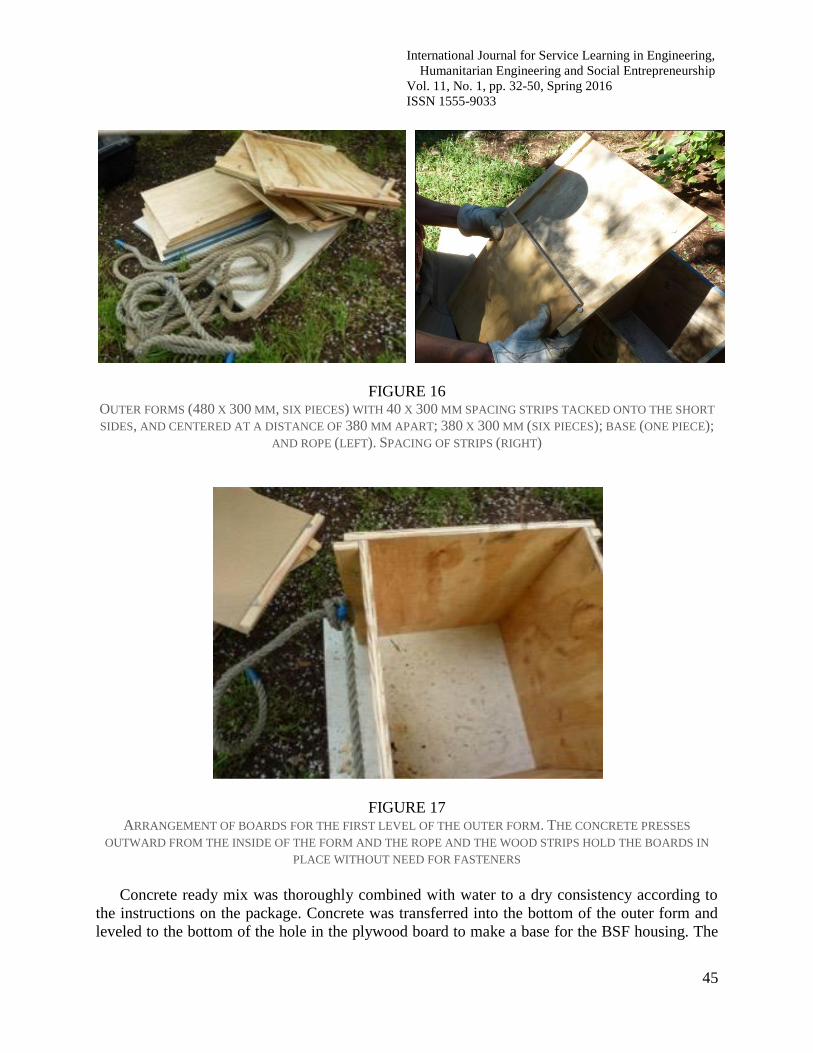
Six boards for the outer form were cut to 380 x 300 mm. The other six were cut to 480 x 300
mm. One of the boards had a hole, sized to accommodate the drain pipe, drilled midway on the
long side and 50 mm from the edge of the short side (see Fig 16). Twelve plywood strips were
cut from scraps left over after cutting the boards. The strips were about 40 x 300 mm. The strips
were tacked onto the short edges of the six, 480 mm wide boards, parallel and at a distance of
380 mm apart (see Figs. 16 and 17). Two boards with strips and two without were arranged on
the base as shown in figure 17 and held in place with a loop of rope.
International Journal for Service Learning in Engineering,
Humanitarian Engineering and Social Entrepreneurship
Vol. 11, No. 1, pp. 32-50, Spring 2016
ISSN 1555-9033
45
FIGURE 16 OUTER FORMS (480 X 300 MM, SIX PIECES) WITH 40 X 300 MM SPACING STRIPS TACKED ONTO THE SHORT
SIDES, AND CENTERED AT A DISTANCE OF 380 MM APART; 380 X 300 MM (SIX PIECES); BASE (ONE PIECE);
AND ROPE (LEFT). SPACING OF STRIPS (RIGHT)
FIGURE 17 ARRANGEMENT OF BOARDS FOR THE FIRST LEVEL OF THE OUTER FORM. THE CONCRETE PRESSES
OUTWARD FROM THE INSIDE OF THE FORM AND THE ROPE AND THE WOOD STRIPS HOLD THE BOARDS IN
PLACE WITHOUT NEED FOR FASTENERS
Concrete ready mix was thoroughly combined with water to a dry consistency according to
the instructions on the package. Concrete was transferred into the bottom of the outer form and
leveled to the bottom of the hole in the plywood board to make a base for the BSF housing. The

International Journal for Service Learning in Engineering,
Humanitarian Engineering and Social Entrepreneurship
Vol. 11, No. 1, pp. 32-50, Spring 2016
ISSN 1555-9033
46
PVC pipe was inserted through the hole in the plywood board and rested on the concrete.
Additional concrete was added to a level that was even with the lip of the pipe (see Fig. 18)
FIGURE 18 VIEW LOOKING DOWN INTO THE FIRST LEVEL OF THE OUTER FORM SHOWING THE CONCRETE BASE OF THE
BSF. THE OPENING OF THE DRAIN PIPE IS VISIBLE IN THE CENTER. THE DRAIN PIPE IS ALSO VISIBLE
PROTRUDING THROUGH THE OUTER FORM IN THE LOWER PORTION OF THE PHOTO
A feed sack was stuffed with a filling material. In this case, black mulch was used for the
filling material. Black mulch is a common and inexpensive yard decoration available in the US.
Sand, grain, small gravel, ground nut shells or similar filling material may be used. The sack was
stuffed firmly and evenly to form a cylindrical shape. The sack was filled to about 2/3 full. A
second feed sack was placed into the mouth of the first and it was stuffed with the granular
material (black mulch) to form an extended cylinder (see Fig. 19, left). Both sacks were lifted
together and placed into the form on top of the pipe and concrete and centered in the space (Fig.
19, right). Next, concrete was added between the bag and the form and tamped frequently to
remove voids. Tamping activity must not disturb the position of the sacks or the concrete base.

International Journal for Service Learning in Engineering,
Humanitarian Engineering and Social Entrepreneurship
Vol. 11, No. 1, pp. 32-50, Spring 2016
ISSN 1555-9033
47
FIGURE 19 FEED SACKS WERE STUFFED WITH GRANULAR MATERIAL AND STACKED ONE INSIDE THE OTHER TO FORM
A CYLINDER TO BECOME THE INNER FORM (LEFT) AND PLACED INTO THE WOODEN OUTER FORM (RIGHT)
Additional outer forms, bags and black mulch were added as each form was filled with concrete
and until all three levels of outer forms were in place. Fig. 20 shows the completed pour at full
height –about 1 meter. Fig. 21 is a view looking down into the completed pour. The concrete was
left to cure for about 48 hours.
FIGURE 20
COMPLETED CONCRETE POUR IN FORMS TO MAKE THE BSF HOUSING

International Journal for Service Learning in Engineering,
Humanitarian Engineering and Social Entrepreneurship
Vol. 11, No. 1, pp. 32-50, Spring 2016
ISSN 1555-9033
48
FIGURE 21
VIEW LOOKING DOWN INTO THE FORM AFTER IT HAS BEEN FILLED WITH CONCRETE TO SURROUND THE
FEED SACKS
Next the forms were removed. After the ropes were loosened, the outer forms came off easily
(see Fig. 22). The mulch was scooped out by hand and the feed sacks were loosened by gently
wiggling them free from the concrete. In some areas, small folds of the feed sack were trapped in
the concrete, but they were removed with light tugging. The final product is shown in Fig. 23,
and a view down into the filter housing cavity is shown in Fig. 24. To more fully cure the
concrete, the BSF housing can be immersed in water or covered with wet cloth or straw for
several days.
FIGURE 22
OUTER FORM PARTIALLY REMOVED TO EXPOSE THE CONCRETE BSF HOUSING

International Journal for Service Learning in Engineering,
Humanitarian Engineering and Social Entrepreneurship
Vol. 11, No. 1, pp. 32-50, Spring 2016
ISSN 1555-9033
49
FIGURE 23
CONCRETE BSF AFTER INNER (FEED SACKS) FORM AND OUTER (PLYWOOD) FORMS WERE REMOVED
FIGURE 24
VIEW INTO THE CAVITY OF THE BSF HOUSING THAT WAS FORMED USING FEED SACKS
RESULTS
Two new methods for constructing concrete biosand water filter housings were developed
and field tested. The resulting concrete BSF structures made as prototypes were structurally
sound and had proper dimensions. The new methods were successful because they were
inexpensive, simple to implement, and made use of materials that were field-available or readily
transportable. Historical issues relating to removal of the inner form were solved, making the

International Journal for Service Learning in Engineering,
Humanitarian Engineering and Social Entrepreneurship
Vol. 11, No. 1, pp. 32-50, Spring 2016
ISSN 1555-9033
50
new methods superior to the existing techniques for small-scale applications. The authors have
taught the boat fender method in Tanzania and it was received with enthusiasm and success.
Future work will continue to teach and refine construction methods for BSF housings and to
discover and test new materials.
ACKNOWLEDGMENT
The authors would like to thank the Department of Biosystems & Agricultural Engineering and
the Robert M. Kerr Food & Agricultural Products Center, both at the Oklahoma State University,
and the WaTER Center, at the University of Oklahoma, for providing facilities and funding for
activities related to the project; and, Pioneer Missions, Eads, Tennessee, for leadership and
funding for projects in Tanzania, Africa.
REFERENCES
1 Lee, T. 2001. Biosand household water filter project in Nepal. M.S. Thesis, Massachusetts Institute of Technology.
Available at: http://web.mit.edu/watsan/Docs/Student%20Theses/Nepal/Lee2001.pdf. Accessed on August 6, 2015.
2 CAWST. 2008. Biosand filter manual. Available for download at: http://resources.cawst.org/package/biosand-
filter-construction-manual_en. Accessed on May 20, 2014.
3Mol, A. and E. Fewster. 2012. Bio-sand filtration filter construction guidelines. Available at:
http://www.biosandfilter.org/biosandfilter/files/webfiles/BioSandFilter_Construction_Guidelines_180912.pdf.
Accessed on July 30, 2015.
4 Lam, E. 2014. Investigations in to the effect of influent total organic carbon concentrations on biosand water
filtration efficiencies and implementation implications in Honduras. M.S. Thesis, Oklahoma State University,
Stillwater. ISBN: 1321071302, 9781321071306
5 Mol, A. and E. Fewster. 2007. Bio-sand filtration mould construction guidelines. Available at:
http://www.biosandfilter.org/biosandfilter/files/webfiles/BioSandFilter_Mould_Construction_Guidelines.pdf.
Accessed on August 4, 2015.