Embed Size (px)
Citation preview
Improved Chemical Agent Monitor
Learn How to Properly PMCS and Operate the ICAM

• Learning Objective• Description and purpose of ICAM• Components • Capabilities • Preventative Maintenance• Pre-operation Test procedures; Self- Test, Confidence Test• Proper procedures when using the Improved Chemical Agent
Monitor• Identifying Chemical contaminations using ICAM• Shut-down Procedures

• Task: Learn the components of the ICAM, how to properly perform PMCS on the ICAM, and also how to operate the ICAM.
• Conditions: In a classroom environment, you are given an Improved Chemical Agent Monitor and a Technical Manual (TM) 3-6665-343-10. The order has been given to perform monitoring procedures for personnel and equipment in a potentially contaminated area.
• Standards: Operate the ICAM by performing monitoring procedures for personnel and equipment that includes preparing the Improved Chemical Agent Monitor for operation and movement.

• The Improved Chemical Agent Monitor is an improvement over the currently fielded CAM. The modular design is less expensive to repair, requires less maintenance, and eliminates depot level repair now required for the CAM. The ICAM also starts up faster after prolonged storage and is more reliable.
• The ICAM is a hand held, soldier operated post attack device for monitoring chemical agent contamination on personnel and equipment.
• The ICAM is for use by personnel who are in full NBC protective posture. It is employed in both monitoring and survey missions and is primarily used to sort contaminated versus clean vehicles, equipment, and personnel. It reduces the burden and enhances the efficiency of the decontamination process. It does not require a specific Military occupational Specialty to operate and is used by a wide variety of units. Also, it is a Non Developmental Item (NDI).
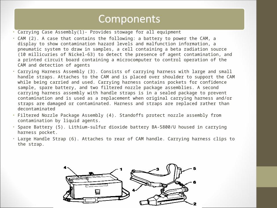
• Carrying Case Assembly(1)- Provides stowage for all equipment• CAM (2). A case that contains the following: a battery to power the CAM, a display to show
contamination hazard levels and malfunction information, a pneumatic system to draw in samples, a cell containing a beta radiation source (10 millicuries of Nickel-63) to detect the presence of agent contamination, and a printed circuit board containing a microcomputer to control operation of the CAM and detection of agents
• Carrying Harness Assembly (3). Consists of carrying harness with large and small handle straps. Attaches to the CAM and is placed over shoulder to support the CAM while being carried and used. Carrying harness contains pockets for confidence sample, spare battery, and two filtered nozzle package assemblies. A second carrying harness assembly with handle straps is in a sealed package to prevent contamination and is used as a replacement when original carrying harness and/or straps are damaged or contaminated. Harness and straps are replaced rather than decontaminated
• Filtered Nozzle Package Assembly (4). Standoffs protect nozzle assembly from contamination by liquid agents.
• Spare Battery (5). Lithium-sulfur dioxide battery BA-5800/U housed in carrying harness pocket.• Large Handle Strap (6). Attaches to rear of CAM handle. Carrying harness clips to the strap.

• Small Handle Strap (7). Attaches to front of CAM handle. Carrying harness clips to the strap.• Confidence Sample (8) The round cross-section end marked G contains nerve agent simulant. The
ribbed end marked H contains mustard agent simulant. Tests the CAM for its ability to detect G and H. Housed in carrying harness pocket.
• Spare Nozzle Protective Cap Assembly (9). Sealed container housing a spare nozzle protective cap assembly. The nozzle protective cap assembly cleans air circulating inside the CAM
• Nozzle Protective Cap Assembly (10). Protects nozzle assembly and ensures that clean air is sampled when CAM is started.
• Nozzle Assembly (11). Chemical agent vapors are drawn in through this inlet for analysis by the CAM.
• Battery (12). Lithium-sulfur dioxide battery BA-5800/U powers the CAM• Battery Cap Assembly (13). Provides access to the battery compartment and holds battery in
place.• Environmental Cap (14). Protects electrical connector and provides a temporary storage place for
the nozzle protective cap assembly when the CAM is in operation. The environmental cap is not removed during operation unless the buzzer is attached.
• Buzzer (15). Attaches to electrical connector and provides an audible alarm when CAM displays two or more bars.
• The ICAM detects vapors of chemical agents by sensing molecular ions of specific mobilities (time of flight) and uses timing and microprocessor techniques to reject interferences.
• Detect Low levels of nerve (G, Vx) and mustard (HD, HN3)• Not affected by common battlefield interferences• Differentiates between nerve and mustard agents• Is a lightweight and handheld monitor• Instantaneous feedback of chemical hazard level• Quickly determine contamination (or none) of front-line
assets (people and equipment)• Reduces the need for decontamination operations• Real-time detection of nerve and blister agents

• CAM-Inspect CAM for broken and/or cracked case. Inspect outside of CAM for dirt, corrosion, distortion, and cracked, broken, and/or missing parts including nozzle protective cap assembly, display, battery cap assembly, environmental cap, and two push-button switches with rubber covers.
• Battery-Twist (counterclockwise) and remove battery cap assembly. Inspect that a battery is installed in receptacle.
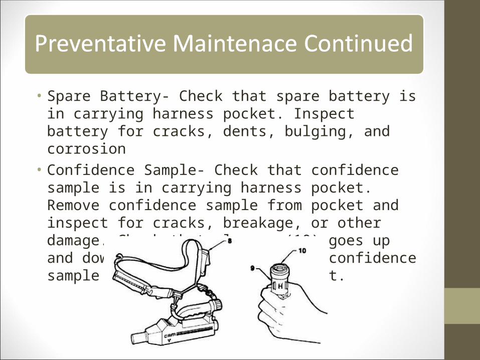
• Spare Battery- Check that spare battery is in carrying harness pocket. Inspect battery for cracks, dents, bulging, and corrosion
• Confidence Sample- Check that confidence sample is in carrying harness pocket. Remove confidence sample from pocket and inspect for cracks, breakage, or other damage. Check that plunger (10) goes up and down for both modes. Return confidence sample to carrying harness pocket.

• Spare Nozzle Protective Cap Assembly- Inspect packing can to ensure no punctures. DO NOT OPEN PACKING CAN UNTIL SPARE NOZZLE PROTECTIVE CAP IS REQUIRED.
• Buzzer- Inspect for cracked, broken, or missing parts. Install battery
• Battery Assembly, Training- Inspect the BAT for dirt and cracked, broken, or missing parts. Remove all dirt from the BAT prior to use
• CAUTION- Make this inspection as quickly as possible to avoid possible contamination of the nozzle protective cap assembly.
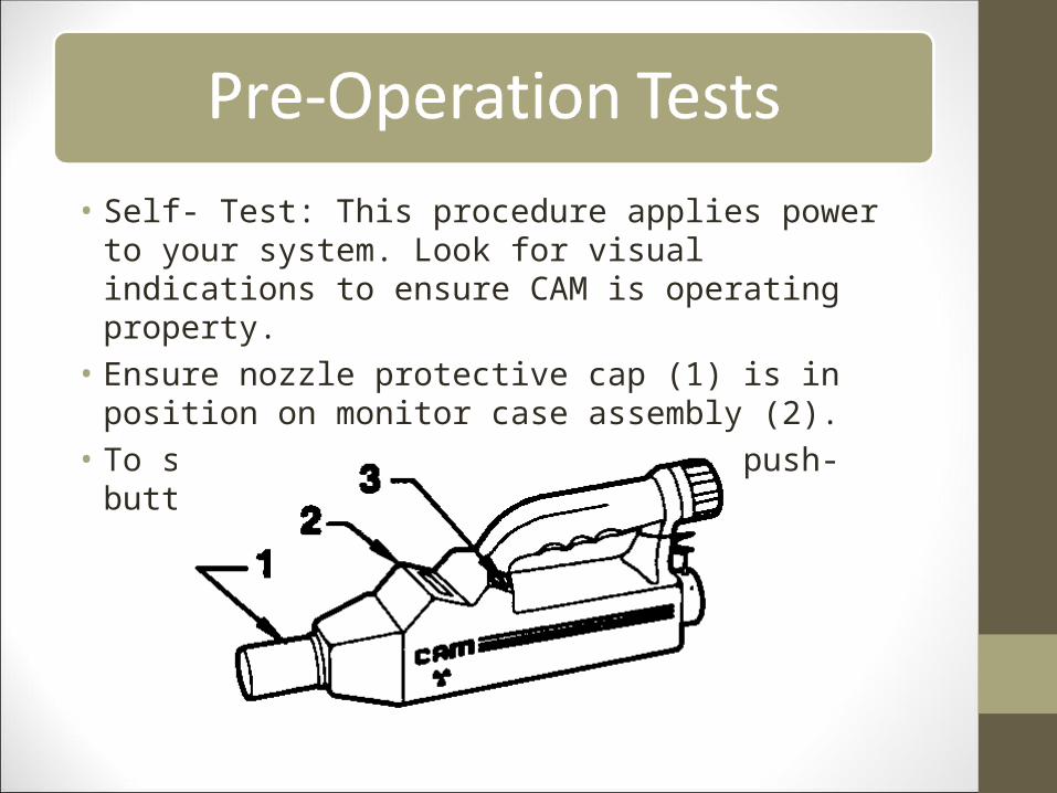
• Self- Test: This procedure applies power to your system. Look for visual indications to ensure CAM is operating property.
• Ensure nozzle protective cap (1) is in position on monitor case assembly (2).
• To start self-test, press ON/OFF push-button switch (3).

• H mode (4) is shown. If G mode is shown, press G/H mode push-button switch. Turn CAM off, then on again. Verify H mode is shown.
• Markers A and B (6) are shown.• All eight bars (7) are shown.• Three vertical dots (8) are shown.• BL (9) is shown.• WAIT (10) is shown.• Display will clear from self-test after 30 seconds (H mode,
WAIT and A and B markers remain).• WAIT clears from display within 2 minutes.

• This test uses a confidence sample (simulant) to detect and display the presence of hazardous chemical nerve or mustard agents. It is performed after completing a selftest or changing modes.
• Twist (counterclockwise) and remove nozzle protective cap (1) from front of CAM (2); place nozzle protective cap onto CAM environmental cap (3) and twist clockwise.
• Place a filtered nozzle standoff onto CAM nozzle assembly, as follows: Pull one filtered nozzle package assembly (4) from pocket (5) of carrying harness.

• Peel back covering from top of filtered nozzle package assembly until one filtered nozzle standoff is exposed.
• Quickly press CAM nozzle assembly into exposed filtered nozzle standoff and remove.
• Lay covering back in place across top of filtered nozzle package assembly. Slide package assembly back into pocket of carrying harness.
• Remove environmental cap and nozzle protective cap combination by twisting counterclockwise.
• Install buzzer onto electrical connector by twisting the ring clockwise.

• Make sure CAM display indicates H mode.• Perform H confidence test as follows:• Remove confidence sample from carrying harness• Grasp confidence sample with H end exposed• Do not allow the CAM to sample the confidence sample
for more than 1 second. Longer than 1 second will saturate the CAM with vapor. It is only necessary that at least three bars show for test verification (do not attempt to have all bars show)• Press firmly CAM nozzle assembly in H end of
confidence sample for 1 second• Remove confidence sample
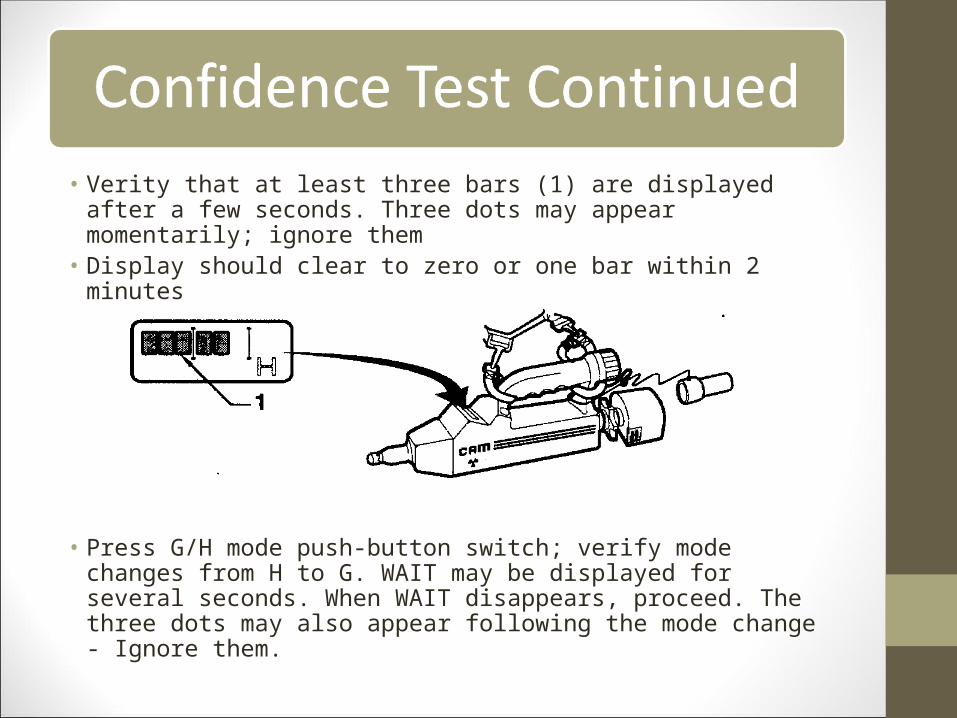
• Verity that at least three bars (1) are displayed after a few seconds. Three dots may appear momentarily; ignore them
• Display should clear to zero or one bar within 2 minutes
• Press G/H mode push-button switch; verify mode changes from H to G. WAIT may be displayed for several seconds. When WAIT disappears, proceed. The three dots may also appear following the mode change - Ignore them.

• Perform G confidence test the same as the H confidence test using the G end of the confidence sample
• Place confidence sample (1) into pocket (2) of carrying harness (3). CAM is ready for operation.

• Proper personnel detection using ICAM• Turn ICAM on• Perform self test (performed in H Mode)• Perform confidence test• Place ICAM in H Mode• Hold ICAM 1/2 inch from the object being monitored• To change from H Mode to G Mode, press G H Mode pushbutton switch;
verify display indicates G Mode. WAIT may be displayed for several seconds. When WAIT has disappeared, proceed. The three dots may also appear following the mode change. Wait until the dots disappear
• Hold CAM 1/2 inch away and monitor object in G Mode• If the operation of the CAM is in doubt at any time, the filtered nozzle
standoff should be removed and the protective cap assembly replaced on the nozzle assembly. When the display has cleared down to one or zero bars, the nozzle protective cap assembly is removed and a new filtered nozzle standoff installed. A confidence test is performed and monitoring can then continue


• Decontaminate a contaminated CAM before performing shutdown procedures
• Remove and discard filtered nozzle standoff from nozzle assembly• Inspect nozzle assembly for indications of moisture; if droplets of
water are noticed, attempt to shake moisture off• Twist (counterclockwise) and remove nozzle protective cap
assembly from environmental cap• Twist (clockwise) and install nozzle protective cap assembly to CAM• If display shows zero bars, press G H Pushbutton Switch to change
modes of operation. Observe display again. If display shows zero bars, CAM is ready for shutdown procedure
• When the display shows zero bars (in both modes), press ON OFF pushbutton switch to shut CAM OFF


![The Influence of Blowing Agent Addition, Glass Fiber Filler … · · 2016-05-23- chemical blowing agent, or CFA - chemical foaming agents) [1-7]. Chemical blowing agents are usually](https://img.dokumen.tips/doc/110x75/5ada4d757f8b9aee348c97b9/the-influence-of-blowing-agent-addition-glass-fiber-filler-chemical-blowing.jpg)